TERMS FOR AUTOMATIC TRANSMISSION REPAIR MANUAL
TERMS FOR AUTOMATIC TRANSMISSION REPAIR MANUAL
TERMS FOR AUTOMATIC TRANSMISSION REPAIR MANUAL

You also want an ePaper? Increase the reach of your titles
YUMPU automatically turns print PDFs into web optimized ePapers that Google loves.
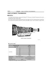
01-6 INTRODUCTION - <strong>TERMS</strong> <strong>FOR</strong> <strong>AUTOMATIC</strong> <strong>TRANSMISSION</strong> <strong>REPAIR</strong><br />
<strong>MANUAL</strong><br />
<strong>TERMS</strong> <strong>FOR</strong> <strong>AUTOMATIC</strong> <strong>TRANSMISSION</strong> <strong>REPAIR</strong> <strong>MANUAL</strong><br />
010ID-01<br />
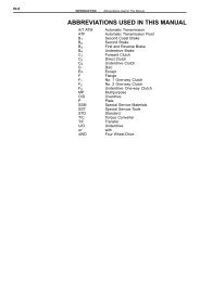
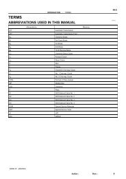
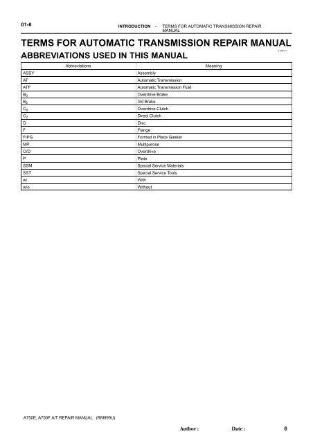
ABBREVIATIONS USED IN THIS <strong>MANUAL</strong><br />
Abbreviations Meaning<br />
ASSY Assembly<br />
AT Automatic Transmission<br />
ATF Automatic Transmission Fluid<br />
B 0<br />
B 2<br />
C 0<br />
C 2<br />
D Disc<br />
A750E, A750F A/T <strong>REPAIR</strong> <strong>MANUAL</strong> (RM999U)<br />
Overdrive Brake<br />
3rd Brake<br />
Overdrive Clutch<br />
Direct Clutch<br />
F Flange<br />
FIPG Formed in Place Gasket<br />
MP Multipurose<br />
O/D Overdrive<br />
P Plate<br />
SSM Special Service Materials<br />
SST Special Service Tools<br />
w/ With<br />
w/o Without<br />
Author: Date:<br />
6
6.4 (65, 57 in.⋅lbf)<br />
Lock Plate<br />
Straight Pin<br />
N⋅m (kgf⋅cm, ft⋅lbf) : Specified torque<br />
Non-reusable part<br />
<strong>AUTOMATIC</strong> <strong>TRANSMISSION</strong> / TRANS - <strong>TRANSMISSION</strong> VALVE BODY ASSY (A750E/A750F)<br />
<strong>TRANSMISSION</strong> VALVE BODY ASSY (A750E/A750F)<br />
COMPONENTS<br />
Shift Solenoid<br />
Valve SLT<br />
A750E, A750F A/T <strong>REPAIR</strong> <strong>MANUAL</strong> (RM999U)<br />
Shift Solenoid<br />
Valve SL2<br />
Straight<br />
Pin<br />
Shift Solenoid<br />
Valve SLU<br />
6.4 (65, 57 in.⋅lbf)<br />
Shift Solenoid<br />
Valve SL1<br />
6.4 (65, 57 in.⋅lbf)<br />
Lock Plate<br />
Straight<br />
Pin<br />
Shift Solenoid<br />
ValveSR<br />
Shift Solenoid<br />
Valve S1<br />
Author: Date:<br />
4007L-02<br />
6.4 (65, 57 in.⋅lbf)<br />
O-ring<br />
Shift Solenoid<br />
Valve S2<br />
40-77<br />
10 (100, 7)<br />
D27981<br />
96
40-56<br />
Snap Ring<br />
Reverse Clutch<br />
Return Spring<br />
Clutch Balancer No.3<br />
Clutch Plate<br />
Forward Clutch Flange<br />
Clutch Balancer No.1<br />
O-Ring<br />
Forward Clutch<br />
Return Spring<br />
<strong>AUTOMATIC</strong> <strong>TRANSMISSION</strong> / TRANS - CLUTCH DRUM & INPUT SHAFT ASSY (A750E/A750F)<br />
CLUTCH DRUM & INPUT SHAFT ASSY (A750E/A750F)<br />
COMPONENTS<br />
Reverse Clutch Piston<br />
Shaft Snap Ring<br />
Direct Clutch Return Spring<br />
Direct Clutch Piston<br />
O-Ring<br />
Clutch Drum<br />
Hole Snap Ring<br />
Input Shaft Oil<br />
Seal Ring<br />
Reverse Clutch Flange<br />
Thrust Bearing Race<br />
Direct Clutch Disc<br />
Hole Snap Ring<br />
Clutch Disc<br />
Shaft Snap<br />
Ring<br />
Reverse Clutch Disc<br />
Clutch Plate<br />
Reverse Clutch Hub<br />
Thrust Needle Roller Bearing<br />
A750E, A750F A/T <strong>REPAIR</strong> <strong>MANUAL</strong> (RM999U)<br />
O-Ring<br />
Clutch Plate<br />
Clutch Balance No.2<br />
40075-02<br />
Forward Clutch Piston<br />
Input Shaft<br />
Forward Clutch Hub<br />
Thrust Bearing<br />
Race No.2<br />
Thrust Needle Roller<br />
Bearing<br />
Clutch Hub (For Multiple Disc Clutch)<br />
Thrust Needle Roller Bearing<br />
Forward Clutch Flange<br />
Reverse Clutch Flange<br />
O-ring<br />
Clutch Drum Thrust<br />
Washer No.2<br />
Snap Ring<br />
Reverse Clutch Reaction Sleeve<br />
Clutch Cushion Plate<br />
Author: Date:<br />
D28526<br />
75
40-50<br />
Front<br />
Oil Pump<br />
Oil Seal<br />
Front Oil Pump Body<br />
N⋅m (kgf⋅cm, ft⋅lbf) : Specified torque<br />
Non-reusable part<br />
<strong>AUTOMATIC</strong> <strong>TRANSMISSION</strong> / TRANS - OIL PUMP ASSY (A750E/A750F)<br />
OIL PUMP ASSY (A750E/A750F)<br />
COMPONENTS<br />
Front Oil Pump<br />
Drive Gear<br />
A750E, A750F A/T <strong>REPAIR</strong> <strong>MANUAL</strong> (RM999U)<br />
Front Oil Pump<br />
Driven Gear<br />
Front Oil<br />
Pump Body<br />
O-ring<br />
Stator Shaft Assy<br />
Front Oil<br />
Pump Body<br />
O-ring<br />
× 14<br />
12 (122, 9)<br />
Author: Date:<br />
Clutch Drum<br />
Oil Seal Ring<br />
40073-02<br />
D27949<br />
69
40-2<br />
COMPONENTS<br />
A750# 4RUNNER<br />
O-Ring<br />
Automatic Transaxle Breather Tube<br />
O-Ring<br />
Park/Neutral Position Switch Assy<br />
Transmission Wire<br />
13 (130, 9)<br />
6.9 (70, 61 in.⋅lbf)<br />
Oil Cooler Union<br />
29 (296, 21)<br />
5.4 (55, 48 in.⋅lbf)<br />
Transmission<br />
Revolution<br />
Sensor<br />
Lock Washer<br />
34 (345, 25)<br />
x2<br />
x6<br />
5.4 (55, 48 in.⋅lbf)<br />
O-Ring<br />
O-Ring<br />
x2<br />
Transmission Revolution Sensor<br />
34 (345, 25)<br />
Automatic Transmission<br />
Housing<br />
57 (581, 42)<br />
Automatic Transaxle<br />
Breather Tube<br />
Transmission Case<br />
Adapter Adapter<br />
A750# 4RUNNER<br />
Transmission<br />
Control Shaft Lever<br />
LH<br />
x4<br />
34 (345, 25)<br />
Transmission Control<br />
Shaft Lever LH<br />
A750E 4RUNNER<br />
A750F 4RUNNER,GX470<br />
34 (345, 25)<br />
Automatic<br />
Transmission<br />
Extension Housing<br />
Oil Seal<br />
x4<br />
34 (345, 25)<br />
Transmission Case<br />
Adapter Oil Seal<br />
x4<br />
x2<br />
34 (345, 25)<br />
Extension Housing Assy<br />
Extension Housing<br />
Dust Deflector<br />
5.4 (55, 48 in.⋅lbf)<br />
N⋅m (kgf⋅cm, ft⋅lbf) : Specified torque Non-reusable part<br />
A750E, A750F A/T <strong>REPAIR</strong> <strong>MANUAL</strong> (RM999U)<br />
<strong>AUTOMATIC</strong> <strong>TRANSMISSION</strong> / TRANS - <strong>AUTOMATIC</strong> <strong>TRANSMISSION</strong> ASSY (A750E/A750F)<br />
O-Ring<br />
5.4 (55, 48 in.⋅lbf)<br />
5.4 (55, 48 in.⋅lbf)<br />
Transmission Case<br />
Adapter Adapter<br />
34 (345, 25)<br />
x4<br />
Washer<br />
16 (163, 12)<br />
x4<br />
Author: Date:<br />
34 (345, 25)<br />
400XJ-01<br />
Transmission Case<br />
Adapter Oil Seal<br />
D28807<br />
21
Manual Valve Lever<br />
Shaft Oil Seal<br />
Manual Valve<br />
Lever Shaft<br />
Transaxle Case Gasket<br />
Manual Valve<br />
Spacer<br />
Spring Pin<br />
C-1<br />
Spring<br />
Brake<br />
Drum Gasket<br />
Spring<br />
Lever Sub-assy<br />
Parking Lock<br />
Accumulator<br />
Valve<br />
C-2 Accumulator Piston<br />
Pawl Bracket B-3 Accumulator Piston<br />
Parking Lock Rod<br />
Spring<br />
O-Ring<br />
7.4 (75, 65 in.⋅lbf)<br />
Parking Lock Pawl<br />
Shaft E-Ring<br />
Parking Lock<br />
Pawl Shaft<br />
Parking Lock Pawl<br />
Torsion spring<br />
Parking Lock Pawl<br />
Automatic Transmission<br />
Oil Pan Gasket<br />
Automatic Transmission<br />
Oil Pan<br />
N⋅m (kgf⋅cm, ft⋅lbf) : Specified torque<br />
Non-reusable part<br />
A750E, A750F A/T <strong>REPAIR</strong> <strong>MANUAL</strong> (RM999U)<br />
<strong>AUTOMATIC</strong> <strong>TRANSMISSION</strong> / TRANS - <strong>AUTOMATIC</strong> <strong>TRANSMISSION</strong> ASSY (A750E/A750F)<br />
O-Ring<br />
Check Ball Body<br />
Oil<br />
Strainer<br />
O-Ring<br />
x19<br />
11 (110, 8)<br />
x20<br />
C-3 Accumulator Piston<br />
Transmission Valve<br />
Body Assy<br />
Valve Body Oil<br />
Strainer Assy<br />
10 (100, 7)<br />
Transmission Oil<br />
Cleaner Magnet<br />
Gasket<br />
Drain Plug<br />
4.4 (45, 39 in.⋅lbf)<br />
Author: Date:<br />
28 (285, 21)<br />
40-3<br />
D28808<br />
22
40-4<br />
Brake Flange No.3<br />
Oil Pump Assy<br />
21 (214, 15)<br />
Front Planetary Gear Assy<br />
1 Way Clutch<br />
Inner Race<br />
Brake Plate No.3<br />
Brake Disc No.3<br />
Thrust Bearing<br />
Race No.1<br />
O-Ring<br />
Thrust Needle<br />
Roller Bearing<br />
Thrust Bearing<br />
Race No.3<br />
1 Way Clutch Assy<br />
Flange<br />
2nd Brake piston<br />
Hole Snap Ring<br />
Clutch Drum & Input Shaft Assy<br />
Thrust Needle<br />
Roller Bearing<br />
N⋅m (kgf⋅cm, ft⋅lbf) : Specified torque<br />
Non-reusable part<br />
A750E, A750F A/T <strong>REPAIR</strong> <strong>MANUAL</strong> (RM999U)<br />
<strong>AUTOMATIC</strong> <strong>TRANSMISSION</strong> / TRANS - <strong>AUTOMATIC</strong> <strong>TRANSMISSION</strong> ASSY (A750E/A750F)<br />
Front Planetary<br />
Ring Gear<br />
Planetary Carrier<br />
Thrust Washer No.2<br />
CTR Planetary<br />
Ring Gear<br />
Brake Plate No.1<br />
Brake Flange No.1<br />
Front Planetary<br />
Ring Gear Flange<br />
2nd Brake<br />
Cylinder<br />
2nd Brake Piston<br />
Snap Ring<br />
2nd Brake Piston<br />
Planetary Carrier<br />
Thrust Washer No.1<br />
Front Planetary Ring<br />
Gear Shaft Snap Ring<br />
2nd Brake piston<br />
Snap Ring<br />
1 Way Clutch Assy No.2<br />
Clutch Drum<br />
Thrust Washer No.2<br />
Brake Disc No.1<br />
2nd Brake<br />
Piston O-Ring<br />
Author: Date:<br />
Brake No.3 Snap Ring<br />
Clutch Drum<br />
Thrust Washer<br />
D28810<br />
23
Snap Ring<br />
Brake Disc No.2<br />
1 Way Clutch<br />
Inner Race<br />
1 Way Clutch<br />
Assy No.3<br />
Brake Piston<br />
Return Spring No.2<br />
Thrust Bearing<br />
Race No.7<br />
Planetary Ring<br />
Gear Flange<br />
Brake Piston No.2<br />
Brake Piston<br />
No.2 O-Ring<br />
Brake Plate No.2<br />
Brake Flange No.2<br />
Brake Piston No.1<br />
O-Ring<br />
Brake Piston<br />
Return Spring<br />
Snap Ring<br />
Non-reusable part<br />
Brake Piston<br />
Return Spring<br />
A750E, A750F A/T <strong>REPAIR</strong> <strong>MANUAL</strong> (RM999U)<br />
<strong>AUTOMATIC</strong> <strong>TRANSMISSION</strong> / TRANS - <strong>AUTOMATIC</strong> <strong>TRANSMISSION</strong> ASSY (A750E/A750F)<br />
<br />
Brake Piston No.1<br />
Thrust Needle<br />
Roller Bearing<br />
Thrust Needle<br />
Roller Bearing<br />
Brake Cylinder No.2<br />
Intermediate Shaft<br />
Brake No.2 Snap Ring<br />
Brake Cylinder No.1<br />
Thrust Bearing<br />
Race No.8<br />
CTR Planetary<br />
Gear Assy<br />
Thrust Bearing<br />
Race No.4<br />
Author: Date:<br />
Planetary<br />
Sun Gear<br />
40-5<br />
D28811<br />
24
40-6<br />
1st & Reverse Brake Return<br />
Spring Shaft Snap Ring<br />
1st & Reverse Brake Piston<br />
Thrust Needle<br />
Roller Bearing<br />
1st & Reverse Brake<br />
Return Spring<br />
Sub-assy<br />
Brake Disc No.4<br />
Brake Reaction<br />
Sleeve<br />
Brake<br />
Reaction Sleeve<br />
Inner Ring<br />
Brake<br />
Reaction<br />
Sleeve Outer Ring<br />
1st & Reverse Brake<br />
Piston O-Ring<br />
Brake Plate No.4<br />
A750E, A750F A/T <strong>REPAIR</strong> <strong>MANUAL</strong> (RM999U)<br />
<strong>AUTOMATIC</strong> <strong>TRANSMISSION</strong> / TRANS - <strong>AUTOMATIC</strong> <strong>TRANSMISSION</strong> ASSY (A750E/A750F)<br />
Thrust Needle<br />
Roller Bearing<br />
Brake Piston No.4<br />
Brake Flange No.4<br />
Brake<br />
Piston No.4<br />
O-Ring<br />
Brake Plate<br />
Stopper Spring<br />
Rear Planetary<br />
Gear Assy<br />
A750E 4RUNNER<br />
Thrust Needle<br />
Roller Bearing<br />
Bearing Race<br />
Author: Date:<br />
Thrust Bearing<br />
Race No.9<br />
Snap Ring<br />
D28812<br />
25
A750E, A750F A/T <strong>REPAIR</strong> <strong>MANUAL</strong> (RM999U)<br />
INTRODUCTION - <strong>TERMS</strong> <strong>FOR</strong> <strong>AUTOMATIC</strong> <strong>TRANSMISSION</strong> <strong>REPAIR</strong><br />
<strong>MANUAL</strong><br />
GLOSSARY OF SAE AND TOYOTA <strong>TERMS</strong><br />
This glossary lists all SAE-J1930 terms and abbreviations used in this manual in compliance with SAE recommendations,<br />
as well as their Toyota equivalents.<br />
SAE<br />
ABBREVIATIONS<br />
SAE <strong>TERMS</strong><br />
TOYOTA <strong>TERMS</strong><br />
( )--ABBREVIATIONS<br />
A/C Air Conditioning Air Conditioner<br />
ACL Air Cleaner Air Cleaner<br />
AIR Secondary Air Injection Air Injection (AI)<br />
AP Accelerator Pedal -<br />
B+ Battery Positive Voltage +B, Battery Voltage<br />
BARO Barometric Pressure -<br />
CAC Charge Air Cooler Inter cooler<br />
CARB Carburetor Carburetor<br />
CFI Continuous Fuel Injection -<br />
CKP Crankshaft Position Crank Angle<br />
CL Closed Loop Closed Loop<br />
CMP Camshaft position Cam Angle<br />
CPP Clutch Pedal Position -<br />
CTOX Continuous Trap Oxidizer -<br />
CTP Closed Throttle Potion -<br />
DFI Direct Fuel Injection (Diesel) Direct Injection (DI)<br />
DI Distributor Ignition -<br />
DLC1<br />
Data Link Connector 1<br />
1: Check Connector<br />
DLC2<br />
Data Link Connector 2<br />
2: Total Diagnosis Communication Link (TDCL)<br />
DLC3<br />
Data Link Connector 3<br />
3: OBD II Diagnostic Connector<br />
DTC Diagnostic Trouble Code Diagnostic Code<br />
DTM Diagnostic Test Mode -<br />
ECL Engine Control Level -<br />
ECM Engine Control Module Engine ECU (Electronic Control Unit)<br />
ECT Engine Control Temperature Coolant Temperature, Water Temperature (THW)<br />
EEPROM<br />
Electrically Erasable Programmable Read Only<br />
memory<br />
Electrically Erasable Programmable Read Only memory<br />
(EEPROM),<br />
Erasable Programmable Read Only memory (EPROM)<br />
EFE Early Fuel Evaporation Cold Mixture Heater (CMH), Heat Control Valve (HCV)<br />
EGR Exhaust Gas Recirculation Exhaust Gas Recirculation (EGR)<br />
EI Electronic Ignition Distributorless Ignition (DI)<br />
EM Engine Modification Engine Modification (EM)<br />
EPROM Erasable Programmable Read Only Memory Programmable Read Only Memory (PROM)<br />
EVAP Evaporative Emission Evaporative Emission Control (EVAP)<br />
FC Fan Control -<br />
FEEPROM<br />
Flash Electrically Erasable Programmable<br />
Read Only Memory<br />
-<br />
FEPROM Flash Erasable Programmable Read Only Memory -<br />
FF Flexible Fuel -<br />
FP Fuel Pump Fuel Pump<br />
GEN Generator Alternator<br />
GND Ground Ground (GND)<br />
HO2S Heated Oxygen Sensor Heated Oxygen Sensor (HO2S)<br />
IAC Idol Air Control Idol Speed Control (ISC)<br />
IAT Intake Air Temperature Intake or Inlet Air Temperature<br />
ICM Ignition Control Module -<br />
IFI Indirect Fuel Injection Indirect Injection<br />
IFS Inertia Fuel-Shutoff -<br />
Author: Date:<br />
01-7<br />
010IE-01<br />
7
01-8 INTRODUCTION - <strong>TERMS</strong> <strong>FOR</strong> <strong>AUTOMATIC</strong> <strong>TRANSMISSION</strong> <strong>REPAIR</strong><br />
<strong>MANUAL</strong><br />
ISC Idle Speed Control -<br />
KS Knock Sensor Knock Sensor<br />
MAF Mass Air Flow Air Flow Meter<br />
MAP Manifold Absolute Pressure<br />
Manifold Pressure<br />
Intake Vacuum<br />
Electric Bleed Air Control Valve (EBCV)<br />
MC Mixture Control<br />
Mixture Control Valve (MCV)<br />
Electric Air Control Valve (EACV)<br />
MDP Manifold Differential Pressure -<br />
MFI Multiport Fuel Injection Electronic Fuel Injection (EFI)<br />
MIL Malfunction Indicator Lamp Check Engine Light<br />
MST Manifold Surface temperature -<br />
MVZ Manifold Vacuum Zone -<br />
NVRAM Non-Volatile Random Access Memory -<br />
O2S Oxygen Sensor Oxygen Sensor, O2 Sensor (O2S) OBD On-Board Diagnostic On-Board Diagnostic (OBD)<br />
OC Oxidation Catalytic Converter Oxidation Catalyst Converter (OC), CC0 OP Open Loop Open Loop<br />
PAIR Pulsed Secondary Air Injection Air Suction (AS)<br />
PCM Powertrain Control Module -<br />
PNP Park/Neutral Position -<br />
PROM Programmable Read Only Memory -<br />
PSP Power Steering Pressure -<br />
PTOX Periodic Trap Oxidizer<br />
Diesel Particulate Filter (DPF)<br />
Diesel Particulate Trap (DPT)<br />
RAM Random Access Memory Random Access Memory (RAM)<br />
RM Relay Module -<br />
ROM Read Only Memory Read Only Memory (ROM)<br />
RPM Engine Speed Engine Speed<br />
SC Supercharger Supercharger<br />
SCB Supercharger Bypass -<br />
SFI Sequential Multiport Fuel Injection Electronic Fuel Injection (EFI), Sequential Injection<br />
SPL Smoke Puff Limiter -<br />
SRI Service Reminder Indicator -<br />
SRT System Readiness Test -<br />
ST Scan Tool -<br />
TB Throttle Body Throttle Body<br />
TBI Throttle Body Fuel Injection<br />
Single Point Injection<br />
Central Fuel Injection (Ci)<br />
TC Turbocharger Turbocharger<br />
TCC Torque Converter Clutch Torque Converter<br />
TCM Transmission Control Module Transmission ECU (Electronic Control Unit)<br />
TP Throttle Position Throttle Position<br />
TR Transmission Range -<br />
TVV Thermal Vacuum Valve<br />
Bimetallic Vacuum Switching Valve (BVSV)<br />
Thermostatic Vacuum Switching Valve (TVSV)<br />
TWC Three-Way Catalytic Converter<br />
Three-Way Catalytic (TWC)<br />
CCRO TWC+OC Three-Way + Oxidation Catalytic Converter CCR + CCO VAF Volume Air Flow Air Flow Meter<br />
VR Voltage Regulator Voltage Regulator<br />
VSS Vehicle Speed Sensor Vehicle Speed Sensor (Read Switch Type)<br />
WOT Wide Open Throttle Full Throttle<br />
A750E, A750F A/T <strong>REPAIR</strong> <strong>MANUAL</strong> (RM999U)<br />
Author: Date:<br />
8
WU-OC Warm Up Oxidation Catalytic Converter -<br />
INTRODUCTION - <strong>TERMS</strong> <strong>FOR</strong> <strong>AUTOMATIC</strong> <strong>TRANSMISSION</strong> <strong>REPAIR</strong><br />
<strong>MANUAL</strong><br />
WU-TWC Warm Up Three-Way Catalytic Converter Manifold Converter<br />
3GR Third Gear -<br />
4GR Fourth Gear -<br />
A750E, A750F A/T <strong>REPAIR</strong> <strong>MANUAL</strong> (RM999U)<br />
Author: Date:<br />
01-9<br />
9
6N<br />
8N<br />
10N<br />
11N<br />
12N<br />
Nut Type<br />
Present Standard<br />
Old Standard Hexagon Nut<br />
Hexagon Nut Cold Forging Nut Cutting Processed Nut<br />
No Mark<br />
No Mark (w/ Washer)<br />
SERVICE SPECIFICATIONS - STANDARD BOLT<br />
HOW TO DETERMINE NUT STRENGTH<br />
*: Nut with 1 or more marks on one side surface of the nut.<br />
No Mark (w/ Washer) No Mark<br />
*<br />
No Mark<br />
Class<br />
4N<br />
5N (4T)<br />
6N<br />
7N (5T)<br />
8N<br />
10N (7T)<br />
HINT:<br />
Use the nut with the same number of the nut strength classification or the greater than the bolt strength classification<br />
number when tightening parts with a bolt and nut.<br />
Example: Bolt = 4T<br />
Nut = 4N or more<br />
A750E, A750F A/T <strong>REPAIR</strong> <strong>MANUAL</strong> (RM999U)<br />
Author: Date:<br />
11N<br />
12N<br />
03-3<br />
0313Q-01<br />
B06432<br />
15
4<br />
5<br />
6<br />
7<br />
8<br />
9<br />
10<br />
11<br />
Hexagon Head Bolt<br />
Normal Recess Bolt Deep Recess Bolt<br />
No Mark<br />
w/ Washer<br />
SERVICE SPECIFICATIONS - STANDARD BOLT<br />
STANDARD BOLT<br />
HOW TO DETERMINE BOLT STRENGTH<br />
No Mark<br />
w/ Washer<br />
A750E, A750F A/T <strong>REPAIR</strong> <strong>MANUAL</strong> (RM999U)<br />
Bolt Type<br />
Stud Bolt Weld Bolt<br />
No Mark<br />
Author: Date:<br />
Class<br />
4T<br />
5T<br />
6T<br />
7T<br />
8T<br />
9T<br />
10T<br />
11T<br />
03-1<br />
0313O-01<br />
B06431<br />
13
INTRODUCTION - HOW TO USE THIS <strong>AUTOMATIC</strong> <strong>TRANSMISSION</strong><br />
<strong>REPAIR</strong> <strong>MANUAL</strong><br />
HOW TO USE THIS <strong>AUTOMATIC</strong> <strong>TRANSMISSION</strong> <strong>REPAIR</strong><br />
<strong>MANUAL</strong><br />
GENERAL IN<strong>FOR</strong>MATION<br />
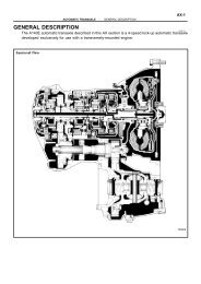
1. GENERAL DESCRIPTION<br />
(a) This manual was created in accordance with SAE J2008.<br />
(b) Generally repair operations can be separated in the following 3 main processes:<br />
1. Diagnosis<br />
2. Removing and Installing, Replacing, Disassembling, Installing and Checking, Adjusting<br />
3. Final Inspection<br />
(c) This manual explains” Removing and Installing, Replacing, Disassembling, Instaling and Checking,<br />
Adjusting”, but” Final inspection” is omitted.<br />
(d) The following essential operations are not written in this manual, however these operations must be<br />
done in the practical situation.<br />
(1) Operation with a jack or lift<br />
(2) Cleaning of a removed part if necessary<br />
(3) Visual check<br />
2. INDEX<br />
(a) An alphabetical INDEX is provided as a section on the end of the book to guide you to the item to be<br />
repaired.<br />
3. PREPARATION<br />
(a) Use of special service tools (SST) and special service materials (SSM) may be required, depending<br />
on the repairing condition. Be sure to use SST and SSM when they are required and follow the working<br />
procedure properly. A list of SST and SSM is in the Preparation section in this manual.<br />
A750E, A750F A/T <strong>REPAIR</strong> <strong>MANUAL</strong> (RM999U)<br />
Author: Date:<br />
01-1<br />
010IB-01<br />
1
01-2 INTRODUCTION - HOW TO USE THIS <strong>AUTOMATIC</strong> <strong>TRANSMISSION</strong><br />
<strong>REPAIR</strong> <strong>MANUAL</strong><br />
4. <strong>REPAIR</strong> PROCEDURES<br />
(a) Component drawing is placed as the section or title if necessary.<br />
(b) Illustrations of the parts catalog are placed as the” disassembled parts drawing” so that it enables you<br />
to understand the fitting condition of the components.<br />
(c) Non-reusable parts, grease applied parts, precoated parts and torque are specified in the components<br />
drawing.<br />
Example:<br />
Oil Seal<br />
N·m (kgf·cm, ft·lbf)<br />
Non-reusable part<br />
: Specified torque<br />
Oil Pump Drive Gear<br />
O-Ring<br />
Oil Pump Driven Gear<br />
Stator Shaft Assy<br />
x13<br />
10 (100, 7)<br />
Oil Seal Ring<br />
(d) Torque, oil applying position, and non-reusable parts are described as important points in the procedure.<br />
NOTICE:<br />
There are cases where such information can only be indicated by an illustration. In those cases, all<br />
the information such as torque, oil, etc. is described in the illustration.<br />
(e) Installing procedure of operation item is performed in the reverse order of the removal, and only the<br />
important points are described.<br />
(f) Only items with points are described in the procedure, and the operational portion and content are<br />
placed using an illustration. In the explanations, details of the operational method, standard value and<br />
notice are placed.<br />
(g) There may be cases where the illustrations of similar models are used. In those cases, the details may<br />
be different from the actual vehicle.<br />
A750E, A750F A/T <strong>REPAIR</strong> <strong>MANUAL</strong> (RM999U)<br />
Author: Date:<br />
D25697<br />
2
Illustration:<br />
what to do and where<br />
SST<br />
INTRODUCTION - HOW TO USE THIS <strong>AUTOMATIC</strong> <strong>TRANSMISSION</strong><br />
<strong>REPAIR</strong> <strong>MANUAL</strong><br />
(h) The procedures are presented in a step-by-step format:<br />
(1) The illustration shows what to do and where to do.<br />
(2) The task heading tells what to do.<br />
(3) The detailed text tells how to perform the task and gives other information such as specifications<br />
and warnings.<br />
Example:<br />
A750E, A750F A/T <strong>REPAIR</strong> <strong>MANUAL</strong> (RM999U)<br />
Set part No.<br />
Task heading: what to do<br />
87. INSTALL FR DIFFERENTIAL CASE FRONT TAPERED<br />
ROLLER BEARING<br />
(a) Using SST and a press, install the front differential case<br />
tapered roller bearing front inner race to the differential<br />
case.<br />
SST 09316-60011 (09316-00011)<br />
Component part No.<br />
Author: Date:<br />
01-3<br />
Detailed text:<br />
how to do task<br />
HINT:<br />
This format provides an experienced technician with a FAST TRACK to the necessary information. The task<br />
heading can be read at a glance when necessary, and the text below provides detailed information. Important<br />
specifications and warnings always stand out in bold type.<br />
5. SERVICE SPECIFICATIONS<br />
(a) Specifications are presented in bold type throughout the manual. You never have to leave the procedure<br />
to look up your specifications. The specifications are also found in the Service Specifications section<br />
for a quick reference.<br />
6. <strong>TERMS</strong> DEFINITION<br />
CAUTION Indicate the possibility of injury to you or other people.<br />
NOTICE Indicate the possibility of damage to the components being repaired.<br />
HINT Provide additional information to help you perform the repair efficiently.<br />
7. SI UNIT<br />
(a) The UNITS used in this manual are primarily expressed according to the SI UNIT (International System<br />
of Unit), and alternately expressed in the metric system and in the English System.<br />
Example:<br />
Torque: 30 N⋅m (310 kgf⋅cm, 22 ft⋅lbf)<br />
D27528<br />
3
<strong>AUTOMATIC</strong> <strong>TRANSMISSION</strong> / TRANS - <strong>AUTOMATIC</strong> <strong>TRANSMISSION</strong> ASSY (A750E/A750F)<br />
<strong>AUTOMATIC</strong> <strong>TRANSMISSION</strong> ASSY (A750E/A750F)<br />
PRECAUTION<br />
NOTICE:<br />
The automatic transmission is composed of highly precision-finished parts, necessitating<br />
careful inspection before reassembly because even a small nick could cause fluid leakage or<br />
affect the performance. The instructions here are organized so that you work on only one component<br />
group at a time. This will help avoid confusion from similar-looking parts of different<br />
sub-assemblies being on your workbench at the same time. The component groups are inspected<br />
and repaired from the converter housing side. As much as possible, complete the inspection,<br />
repair and reassembly before proceeding to the next component group. If a defect is<br />
found in a certain component group during reassembly, inspect and repair this group immediately.<br />
If a component group cannot be assembled because parts are being ordered, be sure to<br />
keep all parts of the group in a separate container while proceeding with disassembly, inspection,<br />
repair and reassembly of other component groups.<br />
Recommended ATF: T-IV<br />
All disassembled parts should be washed clean, and any fluid passages and holes should be<br />
blown through with compressed air.<br />
Dry all parts with compressed air-never use shop rags.<br />
When using compressed air, always aim away from yourself to prevent accidentally spraying<br />
ATF or kerosene on your face.<br />
The recommended automatic transmission fluid or kerosene should be used for cleaning.<br />
After cleaning, the parts should be arranged in the correct order for efficient inspection, repairs,<br />
and reassembly.<br />
When disassembling a valve body, be sure to match each valve together with the corresponding<br />
spring.<br />
New discs for the brakes and clutches that are to be used for replacement must be soaked in<br />
ATF for at least 15 minutes before reassembly.<br />
All oil seal rings, clutch discs, clutch plates, rotating parts, and sliding surfaces should be<br />
coated with ATF prior to reassembly.<br />
All gaskets and rubber O-rings should be replaced.<br />
Do not apply adhesive cements to gaskets and similar parts.<br />
Make sure that the ends of a snap ring are not aligned with one of the cutouts and are installed<br />
in the groove correctly.<br />
If a worn bushing is to be replaced, the sub-assembly containing the bushing must also be replaced.<br />
Check thrust bearings and races for wear or damage. Replace if necessary.<br />
Use petroleum jelly to keep parts in place.<br />
When working with FIPG material, you must follow the below.<br />
Using a razor blade and a gasket scraper, remove all the old packing (FIPG) material from the<br />
gasket surface.<br />
Thoroughly clean all components to remove all the loose material.<br />
Clean both sealing surfaces with a non-residue solvent.<br />
Parts must be reassembled within 10 minutes of application. Otherwise, the packing (FIPG) material<br />
must be removed and reapplied.<br />
A750E, A750F A/T <strong>REPAIR</strong> <strong>MANUAL</strong> (RM999U)<br />
Author: Date:<br />
40-1<br />
4007T-04<br />
20
01-4 INTRODUCTION - <strong>REPAIR</strong> INSTRUCTION <strong>FOR</strong> <strong>AUTOMATIC</strong><br />
<strong>TRANSMISSION</strong> <strong>REPAIR</strong> <strong>MANUAL</strong><br />
<strong>REPAIR</strong> INSTRUCTION <strong>FOR</strong> <strong>AUTOMATIC</strong> <strong>TRANSMISSION</strong><br />
<strong>REPAIR</strong> <strong>MANUAL</strong><br />
PRECAUTION<br />
1. BASIC <strong>REPAIR</strong> HINT<br />
(a) PRECOATED PARTS<br />
(1) Precoated parts are bolts, nuts, etc. that are coated<br />
with a seal lock adhesive at the factory.<br />
(2) If a precoated part is retightened, loosened or<br />
caused to move in any way, it must be recoated with<br />
the specified adhesive.<br />
Seal Lock Adhesive<br />
(3) When reusing precoated parts, clean off the old<br />
adhesive and dry with compressed air. Then apply<br />
Z11554<br />
the specified seal lock adhesive to the bolt, nut or<br />
threads.<br />
NOTICE:<br />
Do the torque checking with the lower limit value of the torque tolerance.<br />
(4) Depending on the seal lock agent to apply, there may be a case where it is necessary to leave<br />
it for a specified time until it hardens.<br />
(b) GASKETS<br />
When necessary, use a sealer on gaskets to prevent leaks.<br />
(c) BOLTS, NUTS AND SCREWS<br />
Carefully observe all specifications for bolt tightening torques. Always use a torque wrench.<br />
A750E, A750F A/T <strong>REPAIR</strong> <strong>MANUAL</strong> (RM999U)<br />
Author: Date:<br />
010IC-01<br />
4
L1 L2<br />
L1<br />
L2<br />
L1<br />
L2<br />
A750E, A750F A/T <strong>REPAIR</strong> <strong>MANUAL</strong> (RM999U)<br />
INTRODUCTION - <strong>REPAIR</strong> INSTRUCTION <strong>FOR</strong> <strong>AUTOMATIC</strong><br />
<strong>TRANSMISSION</strong> <strong>REPAIR</strong> <strong>MANUAL</strong><br />
D02612<br />
D01201<br />
D01202<br />
Author: Date:<br />
01-5<br />
(d) TORQUE WHEN USING EXTENSION TOOL WITH<br />
TORQUE WRENCH<br />
(1) In case of tightening by extending the entire length<br />
of the torque wrench combined with SST or tool, if<br />
you tighten until the reading of the torque wrench<br />
reached the specified torque value, the actual<br />
torque becomes excessive.<br />
(2) In this text, only the specified torque is described.<br />
In case of using SST or extension tool, find the reading<br />
of the torque wrench by the formula.<br />
(3) Formula T’=T x L2/(L1 + L2)<br />
T’ Reading of torque wrench {N⋅m (kgf⋅cm, ft⋅lbf)}<br />
T Torque {N⋅m (kgf⋅cm, ft⋅lbf)}<br />
L1 Length of SST or tool (cm)<br />
L2 Length of torque wrench (cm)<br />
5
03-4<br />
A750E, A750F A/T <strong>REPAIR</strong> <strong>MANUAL</strong> (RM999U)<br />
SERVICE SPECIFICATIONS - <strong>AUTOMATIC</strong> <strong>TRANSMISSION</strong> / TRANSAXLE<br />
<strong>AUTOMATIC</strong> <strong>TRANSMISSION</strong> / TRANSAXLE<br />
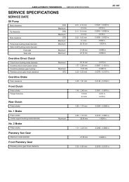
SERVICE DATA<br />
OIL PUMP<br />
Body clearance STD<br />
Maximum<br />
Tip clearance STD<br />
Maximum<br />
Side clearance STD<br />
Maximum<br />
Driver and driven gear thickness 0<br />
1<br />
2<br />
3<br />
4<br />
0.10 - 0.17 mm (0.0039 - 0.0067 in.)<br />
0.17 mm (0.0067 in.)<br />
0.070 - 0.150 mm (0.0028 - 0.0059 in.)<br />
0.150 mm (0.0059 in.)<br />
0.02 - 0.05 mm (0.0008 - 0.0020 in.)<br />
0.05 mm (0.0020 in.)<br />
10.740 - 10.749 mm (0.4228 - 0.4232 in.)<br />
10.750 - 10.759 mm (0.4232 - 0.4236 in.)<br />
10.760 - 10.770 mm (0.4236 - 0.4240 in.)<br />
10.771 - 10.780 mm (0.4241 - 0.4244 in.)<br />
10.781 - 10.790 mm (0.4244 - 0.4248 in.)<br />
Pump body bushing inside diameter Maximum 38.188 mm (1.504 in.)<br />
Stator shaft bushing inside diameter (Front side) Maximum<br />
(Rear side) Maximum<br />
2nd BRAKE<br />
21.577 mm (0.850 in.)<br />
32.08 mm (1.263 in.)<br />
Piston return spring free length STD 15.72 mm (0.619 in.)<br />
B3 BRAKE<br />
Piston stroke 0.42 - 0.72 mm (0.017 - 0.028 in.)<br />
Flange thickness No. 0<br />
No. 1<br />
No. 2<br />
No. 3<br />
FRONT PLANETARY GEAR<br />
2.0 mm (0.079 in.)<br />
2.2 mm (0.087 in.)<br />
2.4 mm (0.094 in.)<br />
2.6 mm (0.102 in.)<br />
Planetary gear bushing inside diameter Maximum 57.48 mm (2.263 in.)<br />
Planetary pinion gear thrust clearance STD<br />
Maximum<br />
BRAKE PISTON No.1<br />
0.2 - 0.6 mm (0.008 - 0.024 in.)<br />
0.65 mm (0.026 in.)<br />
Piston return spring free length STD 17.05 mm (0.671 in.)<br />
CENTER PLANETARY GEAR<br />
Planetary pinion gear thrust clearance STD<br />
Maximum<br />
B2 BRAKE<br />
0.12 - 0.68 mm (0.005 - 0.027 in.)<br />
0.73 mm (0.029 in.)<br />
Piston return spring free length STD 17.45 mm (0.687 in.)<br />
RR PLANETARY RING GEAR FLANGE<br />
Planetary ring gear flange bushing inside diameter Maximum 32.175 mm (1.267 in.)<br />
INTERMEDIATE SHAFT<br />
Intermediate shaft run out Maximum 0.08 mm (0.003 in.)<br />
Intermediate shaft diameter STD A:<br />
B:<br />
C:<br />
D:<br />
Min A:<br />
B:<br />
C:<br />
D:<br />
25.962 - 25.975 mm (1.022 - 1.023 in.)<br />
25.962 - 25.975 mm (1.022 - 1.023 in.)<br />
32.062 - 32.075 mm (1.262 - 1.263 in.)<br />
32.062 - 32.075 mm (1.262 - 1.263 in.)<br />
25.912 mm (1.020 in.)<br />
25.912 mm (1.020 in.)<br />
32.012 mm (1.260 in.)<br />
32.012 mm (1.260 in.)<br />
Author: Date:<br />
0305W-03<br />
16
REAR PLANETARY GEAR<br />
Planetary pinion gear thrust clearance STD<br />
A750E, A750F A/T <strong>REPAIR</strong> <strong>MANUAL</strong> (RM999U)<br />
SERVICE SPECIFICATIONS - <strong>AUTOMATIC</strong> <strong>TRANSMISSION</strong> / TRANSAXLE<br />
Maximum<br />
0.2 - 0.6 mm (0.008 - 0.024 in.)<br />
0.65 mm (0.026 in.)<br />
Planetary gear bushing inside diameter Maximum 20.075 mm (0.790 in.)<br />
1ST & REVERSE BRAKE<br />
Pack clearance 0.8 - 1.1 mm (0.032 - 0.043 in.)<br />
Piston return spring free length STD 23.74 mm (0.935 in.)<br />
H thickness No. 0<br />
No. 2<br />
No. 4<br />
No. 6<br />
No. 8<br />
No. 10<br />
No. 12<br />
No. 14<br />
DIRECT CLUTCH<br />
0 mm (0 in.)<br />
0.2 mm (0.00787 in.)<br />
0.4 mm (0.01575 in.)<br />
0.6 mm (0.02362 in.)<br />
0.8 mm (0.03150 in.)<br />
1.0 mm (0.03937 in.)<br />
1.2 mm (0.04724 in.)<br />
1.4 mm (0.05512 in.)<br />
Pack clearance 0.50 - 0.80 mm (0.020 - 0.032 in.)<br />
Clutch piston return spring free length STD 19.51 mm (0.768 in.)<br />
Flange thickness No. 0<br />
No. 1<br />
No. 2<br />
No. 3<br />
No. 4<br />
No. 5<br />
No. 6<br />
No. 7<br />
No. 8<br />
REVERSE CLUTCH<br />
Reverse clutch drum bushing inside diameter STD<br />
Maximum<br />
3.0 mm (0.118 in.)<br />
3.1 mm (0.122 in.)<br />
3.2 mm (0.126 in.)<br />
3.3 mm (0.130 in.)<br />
3.4 mm (0.134 in.)<br />
3.5 mm (0.138 in.)<br />
3.6 mm (0.142 in.)<br />
3.7 mm (0.146 in.)<br />
3.8 mm (0.150 in.)<br />
35.812 - 35.837 mm (1.4099 - 1.4109 in.)<br />
35.887 mm (1.4129 in.)<br />
Pack clearance 0.50 - 0.80 mm (0.020 - 0.032 in.)<br />
Clutch piston return spring free length STD 21.04 mm (0.828 in.)<br />
Flange thickness No. 0<br />
No. 1<br />
No. 2<br />
No. 3<br />
No. 4<br />
No. 5<br />
No. 6<br />
No. 7<br />
No. 8<br />
No. 9<br />
No. A<br />
<strong>FOR</strong>WARD CLUTCH<br />
Forward clutch drum bushing inside diameter STD<br />
Maximum<br />
2.8 mm (0.110 in.)<br />
2.9 mm (0.114 in.)<br />
3.0 mm (0.118 in.)<br />
3.1 mm (0.122 in.)<br />
3.2 mm (0.126 in.)<br />
3.3 mm (0.130 in.)<br />
3.4 mm (0.134 in.)<br />
3.5 mm (0.138 in.)<br />
3.6 mm (0.142 in.)<br />
3.7 mm (0.146 in.)<br />
3.8 mm (0.150 in.)<br />
26.037 - 26.062 mm (1.0251 - 1.0261 in.)<br />
26.112 mm (1.028 in.)<br />
Pack clearance 0.60 - 0.90 mm (0.0236 - 0.0354 in.)<br />
Author: Date:<br />
03-5<br />
17
03-6<br />
A750E, A750F A/T <strong>REPAIR</strong> <strong>MANUAL</strong> (RM999U)<br />
SERVICE SPECIFICATIONS - <strong>AUTOMATIC</strong> <strong>TRANSMISSION</strong> / TRANSAXLE<br />
Clutch piston return spring free length STD 26.74 mm (1.053 in.)<br />
Flange thickness No. 0<br />
OUTPUT SHAFT BEARING (A750E)<br />
No. 1<br />
No. 2<br />
No. 3<br />
No. 4<br />
No. 5<br />
No. 6<br />
No. 7<br />
No. 8<br />
No. 9<br />
No. A<br />
3.0 mm (0.118 in.)<br />
3.1 mm (0.122 in.)<br />
3.2 mm (0.126 in.)<br />
3.3 mm (0.130 in.)<br />
3.4 mm (0.134 in.)<br />
3.5 mm (0.138 in.)<br />
3.6 mm (0.142 in.)<br />
3.7 mm (0.146 in.)<br />
3.8 mm (0.150 in.)<br />
3.9 mm (0.154 in.)<br />
4.0 mm (0.158 in.)<br />
Clearance 0.05 - 0.33 mm (0.002 - 0.013 in.)<br />
Flange thickness No. 1<br />
No. 2<br />
No. 3<br />
No. 4<br />
No. 5<br />
No. 6<br />
ACCUMULATOR<br />
Spring<br />
Free length/Outer diameter<br />
3.7 mm (0.146 in.)<br />
3.8 mm (0.150 in.)<br />
3.9 mm (0.154 in.)<br />
4.0 mm (0.158 in.)<br />
4.1 mm (0.161 in.)<br />
4.2 mm (0.165 in.)<br />
mm (in.)<br />
B 3 70.5 (2.776) / 19.7 (0.776) Purple<br />
C 2 62.0 (2.441) / 15.9 (0.626) White<br />
C 1 inner 30.4 (1.197) / 11.4 (0.449) Pink<br />
Color<br />
outer 48.76 (1.920) / 16.6 (0.654) Light green<br />
C 3 inner 44.0 (1.732) / 14.0 (0.551) Yellow<br />
outer 73.35 (2.888) / 19.9 (0.784) Red<br />
Author: Date:<br />
18
0313P-01<br />
03-2<br />
-<br />
SERVICE SPECIFICATIONS STANDARD BOLT<br />
14<br />
Author: Date:<br />
A750E, A750F A/T <strong>REPAIR</strong> <strong>MANUAL</strong> (RM999U)<br />
SPECIFIED TORQUE <strong>FOR</strong> STANDARD BOLTS<br />
Specified torque<br />
Class<br />
Diameter<br />
mm<br />
Pitch<br />
mm<br />
Hexagon head bolt Hexagon flange bolt<br />
Class<br />
mm mm<br />
N·m kgf·cm ft·lbf N·m kgf·cm ft·lbf<br />
4T<br />
6<br />
8<br />
10<br />
12<br />
14<br />
16<br />
1<br />
1.25<br />
1.25<br />
1.25<br />
1.5<br />
1.5<br />
5<br />
12.5<br />
26<br />
47<br />
74<br />
115<br />
55<br />
130<br />
260<br />
480<br />
760<br />
1,150<br />
48 in.·lbf<br />
9<br />
19<br />
35<br />
55<br />
83<br />
6<br />
14<br />
29<br />
53<br />
84<br />
-<br />
60<br />
145<br />
290<br />
540<br />
850<br />
-<br />
52 in.·lbf<br />
10<br />
21<br />
39<br />
61<br />
-<br />
5T<br />
6<br />
8<br />
10<br />
12<br />
14<br />
16<br />
1<br />
1.25<br />
1.25<br />
1.25<br />
1.5<br />
1.5<br />
6.5<br />
15.5<br />
32<br />
59<br />
91<br />
140<br />
65<br />
160<br />
330<br />
600<br />
930<br />
1,400<br />
56 in.·lbf<br />
12<br />
24<br />
43<br />
67<br />
101<br />
7.5<br />
17.5<br />
36<br />
65<br />
100<br />
-<br />
75<br />
175<br />
360<br />
670<br />
1,050<br />
-<br />
65 in.·lbf<br />
13<br />
26<br />
48<br />
76<br />
-<br />
6T<br />
6<br />
8<br />
10<br />
12<br />
14<br />
16<br />
1<br />
1.25<br />
1.25<br />
1.25<br />
1.5<br />
1.5<br />
8<br />
19<br />
39<br />
71<br />
110<br />
170<br />
80<br />
195<br />
400<br />
730<br />
1,100<br />
1,750<br />
69 in.·lbf<br />
14<br />
29<br />
53<br />
80<br />
127<br />
9<br />
21<br />
44<br />
80<br />
125<br />
-<br />
90<br />
210<br />
440<br />
810<br />
1,250<br />
-<br />
78 in.·lbf<br />
15<br />
32<br />
59<br />
90<br />
-<br />
7T<br />
6<br />
8<br />
10<br />
12<br />
14<br />
16<br />
1<br />
1.25<br />
1.25<br />
1.25<br />
1.5<br />
1.5<br />
10.5<br />
25<br />
52<br />
95<br />
145<br />
230<br />
110<br />
260<br />
530<br />
970<br />
1,500<br />
2,300<br />
8<br />
19<br />
38<br />
70<br />
108<br />
166<br />
12<br />
28<br />
58<br />
105<br />
165<br />
-<br />
120<br />
290<br />
590<br />
1,050<br />
1,700<br />
-<br />
9<br />
21<br />
43<br />
76<br />
123<br />
-<br />
8T<br />
8<br />
10<br />
12<br />
1.25<br />
1.25<br />
1.25<br />
29<br />
61<br />
110<br />
300<br />
620<br />
1,100<br />
22<br />
45<br />
80<br />
33<br />
68<br />
120<br />
330<br />
690<br />
1,250<br />
24<br />
50<br />
90<br />
9T<br />
8<br />
10<br />
12<br />
1.25<br />
1.25<br />
1.25<br />
34<br />
70<br />
125<br />
340<br />
710<br />
1,300<br />
25<br />
51<br />
94<br />
37<br />
78<br />
140<br />
380<br />
790<br />
1,450<br />
27<br />
57<br />
105<br />
10T<br />
8<br />
10<br />
12<br />
1.25<br />
1.25<br />
1.25<br />
38<br />
78<br />
140<br />
390<br />
800<br />
1,450<br />
28<br />
58<br />
105<br />
42<br />
88<br />
155<br />
430<br />
890<br />
1,600<br />
31<br />
64<br />
116<br />
11T<br />
8<br />
10<br />
12<br />
1.25<br />
1.25<br />
1.25<br />
42<br />
87<br />
155<br />
430<br />
890<br />
1,600<br />
31<br />
64<br />
116<br />
47<br />
97<br />
175<br />
480<br />
990<br />
1,800<br />
35<br />
72<br />
130
A750E, A750F A/T <strong>REPAIR</strong> <strong>MANUAL</strong> (RM999U)<br />
PREPARATION - <strong>AUTOMATIC</strong> <strong>TRANSMISSION</strong> / TRANSAXLE<br />
<strong>AUTOMATIC</strong> <strong>TRANSMISSION</strong> / TRANSAXLE<br />
PREPARATION<br />
SST<br />
Author: Date:<br />
02-1<br />
021YU-01<br />
09223-15020 Oil Seal & Bearing Replacer <strong>AUTOMATIC</strong> <strong>TRANSMISSION</strong><br />
ASSY(A750E/A750F)<br />
09226-10010<br />
Crankshaft Front & Rear Bearing<br />
Replacer<br />
<strong>AUTOMATIC</strong> <strong>TRANSMISSION</strong><br />
ASSY(A750E/A750F)<br />
09308-00010 Oil Seal Puller <strong>AUTOMATIC</strong> <strong>TRANSMISSION</strong><br />
ASSY(A750E/A750F)<br />
09320-89010<br />
Transfer Clutch Spring<br />
Compressor<br />
CLUTCH DRUM & INPUT SHAFT<br />
ASSY(A750E/A750F)<br />
09350-30020 TOYOTA Automatic Transmission<br />
<strong>AUTOMATIC</strong> <strong>TRANSMISSION</strong><br />
Tool Set<br />
ASSY(A750E/A750F)<br />
OIL PUMP ASSY(A750E/A750F)<br />
CLUTCH DRUM & INPUT SHAFT<br />
ASSY(A750E/A750F)<br />
(09350-07020) Oil Pump Puller <strong>AUTOMATIC</strong> <strong>TRANSMISSION</strong><br />
ASSY(A750E/A750F)<br />
(09350-07040) No.2 Piston Spring Compressor CLUTCH DRUM & INPUT SHAFT<br />
ASSY(A750E/A750F)<br />
(09350-07050) No.3 Piston Spring Compressor <strong>AUTOMATIC</strong> <strong>TRANSMISSION</strong><br />
ASSY(A750E/A750F)<br />
(09350-07060) No.1 Snap Ring Expander <strong>AUTOMATIC</strong> <strong>TRANSMISSION</strong><br />
ASSY(A750E/A750F)<br />
(09350-07070) No.2 Snap Ring Expander <strong>AUTOMATIC</strong> <strong>TRANSMISSION</strong><br />
ASSY(A750E/A750F)<br />
CLUTCH DRUM & INPUT SHAFT<br />
ASSY(A750E/A750F)<br />
(09350-07080) Brake Reaction Sleeve Puller <strong>AUTOMATIC</strong> <strong>TRANSMISSION</strong><br />
ASSY(A750E/A750F)<br />
(09350-07090) Brake No.1 Piston Puller <strong>AUTOMATIC</strong> <strong>TRANSMISSION</strong><br />
ASSY(A750E/A750F)<br />
10
02-2<br />
Recomended Tools<br />
Equipment<br />
Feeler gauge<br />
Cylinder Gauge<br />
Vernier calipers<br />
Dial indicator<br />
Micrometer<br />
Feeler gauge<br />
Straight edge<br />
Torque wrench<br />
Angle gauge<br />
V block<br />
A750E, A750F A/T <strong>REPAIR</strong> <strong>MANUAL</strong> (RM999U)<br />
PREPARATION - <strong>AUTOMATIC</strong> <strong>TRANSMISSION</strong> / TRANSAXLE<br />
(09350-071 10) Oil Seal Replacer <strong>AUTOMATIC</strong> <strong>TRANSMISSION</strong><br />
ASSY(A750E/A750F)<br />
(09351-32140) Oil Seal Replacer OIL PUMP ASSY(A750E/A750F)<br />
09387-00070 First & Reverse Brake Wrench CLUTCH DRUM & INPUT SHAFT<br />
ASSY(A750E/A750F)<br />
09710-30050 Suspension Arm Bushing Replacer <strong>AUTOMATIC</strong> <strong>TRANSMISSION</strong><br />
ASSY(A750E/A750F)<br />
09950-70010 Handle Set <strong>AUTOMATIC</strong> <strong>TRANSMISSION</strong><br />
ASSY(A750E/A750F)<br />
(09951-07100) Handle 100 <strong>AUTOMATIC</strong> <strong>TRANSMISSION</strong><br />
ASSY(A750E/A750F)<br />
09031-00030 Pin Punch <strong>AUTOMATIC</strong> <strong>TRANSMISSION</strong><br />
ASSY(A750E/A750F)<br />
Author: Date:<br />
11
Lubricant<br />
Automatic transmission fluid<br />
(LAND CRUISER/ LX470)<br />
Dry fill (2UZ-FE w oil cooler)<br />
Drain and refill (2UZ-FE w oil cooler)<br />
Automatic transmission fluid<br />
(LAND CRUISER)<br />
Dry fill (1HD-FTE w oil cooler)<br />
Drain and refill (1HD-FTE w oil cooler)<br />
Automatic transmission fluid<br />
(LAND CRUISER/ LX470)<br />
Dry fill (2UZ-FE w/o oil cooler)<br />
Drain and refill (2UZ-FE w/o oil cooler)<br />
Automatic transmission fluid<br />
(LAND CRUISER)<br />
Dry fill (1HD-FTE w/o oil cooler)<br />
Drain and refill<br />
(1HD-FTE w/o oil cooler)<br />
Automatic transmission fluid<br />
(4RUNNER,GX470)<br />
Dry fill<br />
Drain and refill<br />
SSM (Special Service Materials)<br />
08826-00090<br />
A750E, A750F A/T <strong>REPAIR</strong> <strong>MANUAL</strong> (RM999U)<br />
PREPARATION - <strong>AUTOMATIC</strong> <strong>TRANSMISSION</strong> / TRANSAXLE<br />
11.6 liters (12.3 US qts, 10.2 Imp. qts)<br />
3.0 liters (3.2 US qts, 2.6 Imp. qts)<br />
12.1 liters (12.8 US qts, 10.6 Imp. qts)<br />
3.0 liters (3.2 US qts, 2.6 Imp. qts)<br />
10.8 liters (11.4 US qts, 9.5 Imp. qts)<br />
3.0 liters (3.2 US qts, 2.6 Imp. qts)<br />
11.4 liters (12.0 US qts, 10.0 Imp. qts)<br />
3.0 liters (3.2 US qts, 2.6 Imp. qts)<br />
11.1 liters (11.7 US qts, 9.8 Imp. qts)<br />
3.0 liters (3.2 US qts, 2.6 Imp. qts)<br />
”Seal Packing 1281,”<br />
THREE BOND 1281 or equivalent<br />
(FIPG)<br />
Author: Date:<br />
ATF TYPE T-IV or equivalent<br />
ATF TYPE T-IV or equivalent<br />
ATF TYPE T-IV or equivalent<br />
ATF TYPE T-IV or equivalent<br />
ATF TYPE T-IV or equivalent<br />
02-3<br />
<strong>AUTOMATIC</strong> <strong>TRANSMISSION</strong><br />
ASSY(A750E/A750F)<br />
12
TORQUE SPECIFICATION<br />
A750E, A750F A/T <strong>REPAIR</strong> <strong>MANUAL</strong> (RM999U)<br />
SERVICE SPECIFICATIONS - <strong>AUTOMATIC</strong> <strong>TRANSMISSION</strong> / TRANSAXLE<br />
Part tightened N·m kgf·cm ft·lbf<br />
Transmission housing x Transmission case 14 mm 34 345 25<br />
17 mm 57 581 42<br />
Automatic transaxle breather tube x Transmission case 5.4 55 48 in.·lbf<br />
Park/Neutral position osition switch assy Bolt<br />
13 130 9<br />
Nut 6.9 70 61 in.·lbf<br />
Transmission wire x Transmission case 5.4 55 48 in.·lbf<br />
Oil cooler tube union x Transmission case 29 296 21<br />
Transmission control shaft lever LH 16 163 12<br />
Transmission revolution sensor x Transmission case 5.4 55 48 in.·lbf<br />
Extension housing assy x Transmission case (A750E) 34 345 25<br />
Transmission case adapter adapter x Transmission case (A750F) 34 345 25<br />
Oil pan x Transmission case 4.4 45 39 in.·lbf<br />
Valve body oil strainer assy x Transmission valve body assy 10 100 7<br />
Transmission valve body assy x Transmission case 11 110 8<br />
Parking lock pawl bracket x Transmission case 7.4 75 65 in.·lbf<br />
Drain plug 28 285 21<br />
Oil pump x Transmission case 21 214 15<br />
Oil pump body x Stator shaft assy 12 122 9<br />
Lock plate x Transmission valve body assy 6.4 65 57 in.·lbf<br />
Shift solenoid valve SR x Transmission valve body assy 6.4 65 57 in.·lbf<br />
Shift solenoid valve S1 x Transmission valve body assy 6.4 65 57 in.·lbf<br />
Shift solenoid valve S2 x Transmission valve body assy 10 100 7<br />
ATF Tem Temperature erature sensor x Transmission valve body assy 36 mm 11 112 8<br />
12 mm 10 100 7<br />
Author: Date:<br />
03-7<br />
0305X-03<br />
19
40-78<br />
OVERHAUL<br />
A750E, A750F A/T <strong>REPAIR</strong> <strong>MANUAL</strong> (RM999U)<br />
<strong>AUTOMATIC</strong> <strong>TRANSMISSION</strong> / TRANS - <strong>TRANSMISSION</strong> VALVE BODY ASSY (A750E/A750F)<br />
D12705<br />
D27982<br />
D27983<br />
D27984<br />
1. REMOVE <strong>TRANSMISSION</strong> VALVE BODY ASSY<br />
(a) Remove the 19 bolts.<br />
(b) Remove the valve body assy.<br />
2. REMOVE SHIFT SOLENOID VALVE SR<br />
(a) Remove the 2 bolts and the shift solenoid valve SR.<br />
Author: Date:<br />
4007M-02<br />
3. REMOVE SHIFT SOLENOID VALVE SLU<br />
(a) Remove the bolt, the 2 straight pins and the solenoid lock<br />
plate.<br />
(b) Remove the shift solenoid valve SLU.<br />
4. REMOVE SHIFT SOLENOID VALVE SL2<br />
(a) Remove the shift solenoid valve SL2.<br />
97
A750E, A750F A/T <strong>REPAIR</strong> <strong>MANUAL</strong> (RM999U)<br />
<strong>AUTOMATIC</strong> <strong>TRANSMISSION</strong> / TRANS - <strong>TRANSMISSION</strong> VALVE BODY ASSY (A750E/A750F)<br />
D27985<br />
D27986<br />
D27987<br />
D27988<br />
D27988<br />
Author: Date:<br />
40-79<br />
5. REMOVE SHIFT SOLENOID VALVE SLT<br />
(a) Remove the bolt, the 2 straight pins and the solenoid lock<br />
plate.<br />
(b) Remove the shift solenoid valve SLT.<br />
6. REMOVE SHIFT SOLENOID VALVE SL1<br />
(a) Remove the shift solenoid valve SL1.<br />
7. REMOVE SHIFT SOLENOID VALVE S1<br />
(a) Remove the bolt and the shift solenoid valve S1.<br />
8. REMOVE SHIFT SOLENOID VALVE S2<br />
(a) Remove the bolt and the shift solenoid valve S2.<br />
(b) Remove the O-ring from the shift solenoid valve S2.<br />
9. INSTALL SHIFT SOLENOID VALVE S2<br />
(a) Install the O-ring to the shift solenoid valve S2.<br />
(b) Install the bolt and the shift solenoid valve S2.<br />
Torque: 10 N·m (102 kgf·cm, 7 ft·lbf)<br />
98
40-80<br />
A750E, A750F A/T <strong>REPAIR</strong> <strong>MANUAL</strong> (RM999U)<br />
<strong>AUTOMATIC</strong> <strong>TRANSMISSION</strong> / TRANS - <strong>TRANSMISSION</strong> VALVE BODY ASSY (A750E/A750F)<br />
D27987<br />
D27986<br />
D27985<br />
D27984<br />
D27983<br />
10. INSTALL SHIFT SOLENOID VALVE S1<br />
(a) Install the O-ring to the shift solenoid valve S1.<br />
(b) Install the bolt and the shift solenoid valve S1.<br />
Torque: 6.4 N·m (65 kgf·cm, 57 in.⋅lbf)<br />
11. INSTALL SHIFT SOLENOID VALVE SL1<br />
(a) Install the shift solenoid valve SL1.<br />
12. INSTALL SHIFT SOLENOID VALVE SLT<br />
(a) Install the shift solenoid valve SLT.<br />
(b) Install the bolt, the 2 straight pins and the solenoid lock<br />
plate.<br />
Torque: 6.4 N·m (65 kgf·cm, 57 in.⋅lbf)<br />
13. INSTALL SHIFT SOLENOID VALVE SL2<br />
(a) Install the shift solenoid valve SL2.<br />
14. INSTALL SHIFT SOLENOID VALVE SLU<br />
(a) Install the shift solenoid valve SLU.<br />
(b) Install the bolt, the 2 straight pins and the solenoid lock<br />
plate.<br />
Torque: 6.4 N·m (65 kgf·cm, 57 in.⋅lbf)<br />
Author: Date:<br />
99
A<br />
B<br />
A<br />
Pin<br />
A A A<br />
A750E, A750F A/T <strong>REPAIR</strong> <strong>MANUAL</strong> (RM999U)<br />
<strong>AUTOMATIC</strong> <strong>TRANSMISSION</strong> / TRANS - <strong>TRANSMISSION</strong> VALVE BODY ASSY (A750E/A750F)<br />
D27982<br />
D12707<br />
A<br />
A<br />
D12705<br />
15. INSTALL SHIFT SOLENOID VALVE SR<br />
(a) Instal the 2 bolts and the shift solenoid valve SR.<br />
Torque: 6.4 N·m (65 kgf·cm, 57 in.⋅lbf)<br />
Author: Date:<br />
40-81<br />
16. INSTALL <strong>TRANSMISSION</strong> VALVE BODY ASSY<br />
(a) Align the groove of the manual valve with the pin of the<br />
lever.<br />
(b) Install the 19 bolts.<br />
Torque: 11 N·m (110 kgf·cm, 8 ft·lbf)<br />
HINT:<br />
Each bolt length is indicated below.<br />
Blot length:<br />
Bolt A: 25 mm (0.98 in.)<br />
Bolt B: 36 mm (1.42 in.)<br />
100
OVERHAUL<br />
Oil Pump<br />
Torque<br />
Converter<br />
Clutch<br />
A750E, A750F A/T <strong>REPAIR</strong> <strong>MANUAL</strong> (RM999U)<br />
<strong>AUTOMATIC</strong> <strong>TRANSMISSION</strong> / TRANS - CLUTCH DRUM & INPUT SHAFT ASSY (A750E/A750F)<br />
D27995<br />
D27996<br />
D27997<br />
D27998<br />
Author: Date:<br />
40-57<br />
400XL-01<br />
1. FIX CLUTCH DRUM & INPUT SHAFT ASSY<br />
(a) Place the oil pump onto the torque converter clutch, and<br />
then place the clutch drum & input shaft assy onto the oil<br />
pump.<br />
2. REMOVE REVERSE CLUTCH HUB SUB-ASSY<br />
(a) Using a screwdriver, remove the snap ring from the clutch<br />
drum and the input shaft assy.<br />
(b) Remove the reverse clutch hub sub assy, the reverse<br />
clutch reaction sleeve, the clutch cushion, the plate reverse<br />
clutch flange, the 5 reverse clutch discs, and the 4<br />
clutch plates from the clutch drum assy.<br />
3. REMOVE REVERSE CLUTCH REACTION SLEEVE<br />
(a) Remove the reverse clutch reaction sleeve from the reverse<br />
clutch hub sub assy.<br />
76
40-58<br />
D<br />
D<br />
D<br />
D<br />
D<br />
Cushion Plate<br />
F<br />
P<br />
P<br />
P<br />
P<br />
A750E, A750F A/T <strong>REPAIR</strong> <strong>MANUAL</strong> (RM999U)<br />
<strong>AUTOMATIC</strong> <strong>TRANSMISSION</strong> / TRANS - CLUTCH DRUM & INPUT SHAFT ASSY (A750E/A750F)<br />
D27999<br />
D01216<br />
D28000<br />
D28001<br />
D28500<br />
4. REMOVE REAR CLUTCH DISC<br />
(a) Remove the clutch cushion plate, the reverse clutch<br />
flange, the 4 plates and the 5 discs from the reverse clutch<br />
hub.<br />
5. INSPECT REAR CLUTCH DISC<br />
(a) Check whether the sliding surface of the disc, the plate<br />
and the flange are worn or burnt. If necessary, replace<br />
them.<br />
HINT:<br />
If the lining of the disc is peeled off or discolored, or even<br />
if only a part of the printed numbers is damaged, replace<br />
all discs.<br />
Before assembling new discs, soak them in ATF for at<br />
least 15 minutes.<br />
6. INSPECT REVERSE CLUTCH HUB SUB-ASSY<br />
(a) Using a dial indicator, measure the inside diameter of the<br />
reverse clutch hub bushing.<br />
Standard drum bushing:<br />
35.812 - 35.837 mm (1.4099 - 1.4109 in.)<br />
Maximum drum bushing: 35.887 mm (1.4129 in.)<br />
If the inside diameter is greater than the maximum, replace the<br />
reverse clutch hub.<br />
7. REMOVE <strong>FOR</strong>WARD CLUTCH HUB SUB-ASSY<br />
(a) Remove the forward clutch hub sub assy from the clutch<br />
drum assy.<br />
(b) Remove the 2 thrust needle roller bearings from the forward<br />
clutch hub sub assy.<br />
Author: Date:<br />
77
Thrust Bearing Race No.2<br />
D28501<br />
D28502<br />
Input Shaft<br />
Thrust<br />
Bearing<br />
Race RR<br />
A750E, A750F A/T <strong>REPAIR</strong> <strong>MANUAL</strong> (RM999U)<br />
<strong>AUTOMATIC</strong> <strong>TRANSMISSION</strong> / TRANS - CLUTCH DRUM & INPUT SHAFT ASSY (A750E/A750F)<br />
D28503<br />
D28504<br />
D28505<br />
Author: Date:<br />
40-59<br />
8. INSPECT <strong>FOR</strong>WARD CLUTCH HUB SUB-ASSY<br />
(a) Using a dial indicator, measure the inside diameter of the<br />
forward clutch hub bushing.<br />
Standard drum bushing:<br />
26.037 - 26.062 mm (1.0251 - 1.0261 in.)<br />
Maximum drum bushing: 26.112 mm (1.028 in.)<br />
If the inside diameter is greater than the maximum, replace the<br />
forward clutch hub.<br />
9. REMOVE MULTIPLE DISC CLUTCH CLUTCH HUB<br />
(a) Remove the multiple disc clutch clutch hub from the clutch<br />
drum assy.<br />
(b) Remove the thrust bearing race No.2 and the input shaft<br />
thrust bearing race RR from the multiple disc clutch clutch<br />
hub.<br />
10. REMOVE INPUT SHAFT ASSY<br />
(a) Remove the thrust needle roller bearing from the clutch<br />
drum assy.<br />
(b) Remove the input shaft assy from the clutch drum assy.<br />
78
40-60<br />
D28518<br />
A750E, A750F A/T <strong>REPAIR</strong> <strong>MANUAL</strong> (RM999U)<br />
<strong>AUTOMATIC</strong> <strong>TRANSMISSION</strong> / TRANS - CLUTCH DRUM & INPUT SHAFT ASSY (A750E/A750F)<br />
D29677<br />
D28519<br />
D28520<br />
D01216<br />
11. REMOVE INPUT SHAFT OIL SEAL RING<br />
(a) Remove the 3 oil seal rings from the input shaft assy.<br />
12. REMOVE <strong>FOR</strong>WARD MULTIPLE DISC CLUTCH<br />
CLUTCH DISC<br />
(a) Using a screwdriver, remove the hole snap ring.<br />
(b) Remove the 2 flanges, the 6 discs and the 5 plates from<br />
the input shaft assy.<br />
13. INSPECT <strong>FOR</strong>WARD MULTIPLE DISC CLUTCH<br />
CLUTCH DISC<br />
(a) Check whether the sliding surface of the disc, the plate<br />
and the flange are worn or burnt. If necessary, replace<br />
them.<br />
HINT:<br />
If the lining of the disc is peeled off or discolored, or even<br />
if only a part of the printed numbers is damaged, replace<br />
all discs.<br />
Author: Date:<br />
79
A750E, A750F A/T <strong>REPAIR</strong> <strong>MANUAL</strong> (RM999U)<br />
<strong>AUTOMATIC</strong> <strong>TRANSMISSION</strong> / TRANS - CLUTCH DRUM & INPUT SHAFT ASSY (A750E/A750F)<br />
D28521<br />
D28522<br />
D28523<br />
C59838<br />
Author: Date:<br />
40-61<br />
Before assembling new discs, soak them in ATF for at<br />
least 15 minutes.<br />
14. REMOVE CLUTCH BALANCER NO.1<br />
(a) Place SST on the clutch balancer No.1, and compress the<br />
return spring with a press.<br />
SST 09350-30020 (09350-07040, 09350-07070)<br />
(b) Remove the clutch balancer No.1 and the forwerd clutch<br />
return spring from the inputshaft assy.<br />
(c) Remove the O-ring from the clutch balancer No.1.<br />
15. INSPECT <strong>FOR</strong>WARD CLUTCH RETURN SPRING<br />
SUB-ASSY<br />
(a) Using a vernier calipers, measure the free length of the<br />
spring together with the spring seat.<br />
Standard free length: 26.74 mm (1.053 in.)<br />
80
40-62<br />
A750E, A750F A/T <strong>REPAIR</strong> <strong>MANUAL</strong> (RM999U)<br />
<strong>AUTOMATIC</strong> <strong>TRANSMISSION</strong> / TRANS - CLUTCH DRUM & INPUT SHAFT ASSY (A750E/A750F)<br />
D28524<br />
D28525<br />
D28506<br />
D28507<br />
16. REMOVE <strong>FOR</strong>WARD CLUTCH PISTON<br />
(a) Holding the forward clutch piston by hand, apply compressed<br />
air (392 kPa, 4.0 kgf/cm 2 , 57 psi) to the inputshaft<br />
to remove the forward clutch piston.<br />
(b) Remove the 2 O-rings from the forward clutch piston.<br />
17. REMOVE REVERSE CLUTCH FLANGE<br />
(a) Remove the reverse clutch flange from the clutch drum<br />
assy.<br />
18. REMOVE DIRECT CLUTCH DISK<br />
(a) Using a screwdriver, remove the 2 hole snap rings from<br />
the clutch drum assy.<br />
Author: Date:<br />
81
SST<br />
A750E, A750F A/T <strong>REPAIR</strong> <strong>MANUAL</strong> (RM999U)<br />
<strong>AUTOMATIC</strong> <strong>TRANSMISSION</strong> / TRANS - CLUTCH DRUM & INPUT SHAFT ASSY (A750E/A750F)<br />
D28508<br />
D01216<br />
D28509<br />
D28510<br />
Author: Date:<br />
40-63<br />
(b) Remove the reverse clutch flange, the 6 plates and the 5<br />
discs from the clutch drum assy.<br />
19. INSPECT DIRECT CLUTCH DISK<br />
(a) Check whether the sliding surface of the disc, the plate<br />
and the flange are worn or burnt. If necessary, replace<br />
them.<br />
HINT:<br />
If the lining of the disc is peeled off or discolored, or even<br />
if only a part of the printed numbers is damaged, replace<br />
all discs.<br />
Before assembling new discs, soak them in ATF for at<br />
least 15 minutes.<br />
20. REMOVE CLUTCH BALANCER NO.3<br />
(a) Place SST on the clutch balancer No.3, and compress the<br />
return spring with a press.<br />
SST 09387-00070, 09350-30020 (09350-07070)<br />
21. REMOVE REVERSE CLUTCH RETURN SPRING<br />
SUB-ASSY<br />
(a) Remove the reverse clutch return spring and the O-ring<br />
from the reverse clutch piston.<br />
82
40-64<br />
SST<br />
A750E, A750F A/T <strong>REPAIR</strong> <strong>MANUAL</strong> (RM999U)<br />
<strong>AUTOMATIC</strong> <strong>TRANSMISSION</strong> / TRANS - CLUTCH DRUM & INPUT SHAFT ASSY (A750E/A750F)<br />
C59838<br />
D28511<br />
D28512<br />
D28513<br />
D28514<br />
22. INSPECT REVERSE CLUTCH RETURN SPRING<br />
SUB-ASSY<br />
(a) Using a vernier calipers, measure the free length of the<br />
spring together with the spring seat.<br />
Standard free length: 21.04 mm (0.828 in.)<br />
23. REMOVE REVERSE CLUTCH PISTON SUB-ASSY<br />
(a) Remove the reverse clutch piston, sub assy from the<br />
clutch drum sub assy.<br />
(b) Remove the O-ring from the reverse clutch piston sub<br />
assy.<br />
(c) Remove the O-ring from the clutch drum sub assy.<br />
24. REMOVE DIRECT CLUTCH PISTON SUB-ASSY<br />
(a) Place SST on the direct clutch piston, and compress the<br />
return spring with a press.<br />
SST 09320-89010, 09350-30020 (09350-07070)<br />
Author: Date:<br />
83
A750E, A750F A/T <strong>REPAIR</strong> <strong>MANUAL</strong> (RM999U)<br />
<strong>AUTOMATIC</strong> <strong>TRANSMISSION</strong> / TRANS - CLUTCH DRUM & INPUT SHAFT ASSY (A750E/A750F)<br />
D28515<br />
D28516<br />
D28517<br />
D28816<br />
C59838<br />
Author: Date:<br />
40-65<br />
(b) Using 2 screw drivers, remove the direct clutch piston sub<br />
assy from the clutch drum.<br />
(c) Remove the O-ring from the clutch drum.<br />
(d) Remove the clutch balancer No.2 and the direct clutch return<br />
spring sub assy from the direct clutch piston sub<br />
assy.<br />
(e) Remove the 2 O-rings from the direct clutch piston Sub-<br />
Assy.<br />
25. INSPECT DIRECT CLUTCH RETURN SPRING<br />
SUB-ASSY<br />
(a) Using a vernier calipers, measure the free length of the<br />
spring together with the spring seat.<br />
Standard free length: 19.51 mm (0.768 in.)<br />
84
40-66<br />
SST<br />
A750E, A750F A/T <strong>REPAIR</strong> <strong>MANUAL</strong> (RM999U)<br />
<strong>AUTOMATIC</strong> <strong>TRANSMISSION</strong> / TRANS - CLUTCH DRUM & INPUT SHAFT ASSY (A750E/A750F)<br />
D28816<br />
D28517<br />
D28516<br />
D28514<br />
26. INSTALL DIRECT CLUTCH PISTON SUB-ASSY<br />
(a) Coat 2 new O-rings with ATF, and install them in the direct<br />
clutch piston.<br />
(b) Install the clutch balancer No.2 and the direct clutch return<br />
spring to the direct clutch piston sub assy.<br />
(c) Coat a new O-ring with ATF, and install them on the clutch<br />
drum sub assy.<br />
(d) Be careful not to damage the O-rings. Press in the direct<br />
clutch piston into the clutch drum with both hands.<br />
(e) Place SST on the direct clutch piston, and compress the<br />
return spring with a press.<br />
SST 09320-89010, 09350-30020 (09350-07070)<br />
(f) Install the snap ring with a snap ring expander.<br />
NOTICE:<br />
Be sure the end gap of the snap ring is not aligned<br />
with the spring retainer claw.<br />
Stop Pressing when the spring sheet is lowered to the<br />
place 1 - 2 mm (0.039 - 0.078 in.) from the snap ring<br />
groove to prevent the spring sheet from being deformed.<br />
Do not expand the snap ring excessively.<br />
Author: Date:<br />
85
Stopper<br />
A750E, A750F A/T <strong>REPAIR</strong> <strong>MANUAL</strong> (RM999U)<br />
<strong>AUTOMATIC</strong> <strong>TRANSMISSION</strong> / TRANS - CLUTCH DRUM & INPUT SHAFT ASSY (A750E/A750F)<br />
D28536<br />
D28513<br />
D28512<br />
D28511<br />
D28510<br />
Author: Date:<br />
40-67<br />
(g) Set the end gap of the snap ring in the piston as shown<br />
in the illustration.<br />
27. INSTALL REVERSE CLUTCH PISTON SUB-ASSY<br />
(a) Coat a new O-ring with ATF, and install it on the clutch<br />
drum sub assy.<br />
(b) Coat a new O-ring with ATF, and install it on the reverse<br />
clutch piston sub assy.<br />
(c) Be careful not to damage the O-ring. Press in the clutch<br />
drum sub assy into the reverse clutch piston with both<br />
hands.<br />
28. INSTALL REVERSE CLUTCH RETURN SPRING<br />
SUB-ASSY<br />
(a) Coat a new O-ring with ATF, and install it on the reverse<br />
clutch piston sub assy.<br />
(b) Install the reverse clutch return spring onto the reverse<br />
clutch piston sub assy.<br />
86
40-68<br />
GAP<br />
F<br />
P<br />
P<br />
P<br />
P<br />
P<br />
P<br />
SST<br />
A750E, A750F A/T <strong>REPAIR</strong> <strong>MANUAL</strong> (RM999U)<br />
<strong>AUTOMATIC</strong> <strong>TRANSMISSION</strong> / TRANS - CLUTCH DRUM & INPUT SHAFT ASSY (A750E/A750F)<br />
D<br />
D<br />
D<br />
D<br />
D<br />
D28509<br />
D28534<br />
D28508<br />
29. INSTALL CLUTCH BALANCER NO.3<br />
(a) Place SST on the clutch balancer No.3, and compress the<br />
clutch balancer with a press.<br />
SST 09387-00070, 09350-30020 (09350-07070)<br />
(b) Install the snap ring with a snap ring expander.<br />
(c) Be sure the end gap of the snap ring is not aligned with<br />
the spring retainer claw.<br />
NOTICE:<br />
Stop pressing when the spring sheet is lowered to the<br />
place 1 - 2 mm (0.039 - 0.078 in.) from the snap ring<br />
groove to prevent the spring sheet from being deformed.<br />
Do not expand the snap ring excessively.<br />
(d) Set the end gap of the snap ring in the piston as shown<br />
in the illustration.<br />
30. INSTALL DIRECT CLUTCH DISK<br />
(a) Install the reverse clutch flange, the 6 plates and the 5<br />
discs on the clutch drum sub assy.<br />
Author: Date:<br />
87
A<br />
A750E, A750F A/T <strong>REPAIR</strong> <strong>MANUAL</strong> (RM999U)<br />
<strong>AUTOMATIC</strong> <strong>TRANSMISSION</strong> / TRANS - CLUTCH DRUM & INPUT SHAFT ASSY (A750E/A750F)<br />
D28507<br />
D29841<br />
D28506<br />
Author: Date:<br />
40-69<br />
(b) Using a screwdriver, install the 2 hole snap rings on the<br />
clutch drum sub assy.<br />
31. INSPECT PACK CLEARANCE OF DIRECT CLUTCH<br />
(a) Using a dial gauge, measure the moving distance (distance<br />
A) of the clutch flange at the both end across a diameter<br />
while blowing air from the oil hole as shown in the<br />
illustration, and calculate the average.<br />
Pack Clearance: 0.5 - 0.8 mm<br />
NOTICE:<br />
Install a selective flange (t 3.4 mm) when measuring the<br />
moving distance. (shaded area in the illustration.)<br />
HINT:<br />
Flange moving distance A = 0.26 - 1.14 mm<br />
Pack Clearance = Flange moving distance A - 0.05 mm<br />
(b) If the pack clearance is outside the standard, select &<br />
install a clutch flange that makes the pack clearance to be<br />
within the standard.<br />
HINT:<br />
Select the flange from 9 kinds (in thickness) of the selective<br />
flanges to adjust the pack clearance.<br />
Flange thickness<br />
No. Thickness No. Thickness<br />
0 3.0 (0.118) 5 3.5 (0.138)<br />
1 3.1 (0.122) 6 3.6 (0.142)<br />
2 3.2 (0.126) 7 3.7 (0.146)<br />
3 3.3 (0.130) 8 3.8 (0.150)<br />
4 3.4 (0.134) - -<br />
32. INSTALL REVERSE CLUTCH FLANGE<br />
(a) Install the reverse clutch flange to the clutch drum sub<br />
assy.<br />
88
40-70<br />
A<br />
A750E, A750F A/T <strong>REPAIR</strong> <strong>MANUAL</strong> (RM999U)<br />
<strong>AUTOMATIC</strong> <strong>TRANSMISSION</strong> / TRANS - CLUTCH DRUM & INPUT SHAFT ASSY (A750E/A750F)<br />
D29843<br />
D29844<br />
33. INSTALL REVERSE CLUTCH REACTION SLEEVE<br />
(a) Install the reverse clutch reaction sleeve, the clutch cushion<br />
plate, the reverse clutch flange, the 5 reverse clutch<br />
discs, and the 4 clutch plates to the reverse clutch hub.<br />
(b) Using a screwdriver, install the hole snap ring.<br />
34. INSPECT PACK CLEARANCE OF REVERSE CLUTCH<br />
(a) Using a dial gauge, measure the reverse clutch piston<br />
stroke (distance A) and the moving distance (distance B)<br />
of the reverse clutch flange at the both end across a diameter<br />
while blowing air (392 kPa, 4 kgf/cm 2 , 57 psi) from the<br />
oil hole as shown in the illustration, and calculate the average.<br />
Pack Clearance: 0.5 - 0.8 mm<br />
NOTICE:<br />
Install a selective flange (t 3.3 mm) when measuring the<br />
moving distance. (shaded area in the illustration.)<br />
HINT:<br />
Piston stroke A = 1.05 - 2.15 mm<br />
Flange moving distance B = 0.72 - 1.08 mm<br />
Pack Clearance = Piston stroke A - Flange moving distance B<br />
- 0.06<br />
B<br />
Author: Date:<br />
D28538<br />
89
A750E, A750F A/T <strong>REPAIR</strong> <strong>MANUAL</strong> (RM999U)<br />
<strong>AUTOMATIC</strong> <strong>TRANSMISSION</strong> / TRANS - CLUTCH DRUM & INPUT SHAFT ASSY (A750E/A750F)<br />
D29844<br />
D29843<br />
D28525<br />
Author: Date:<br />
40-71<br />
(b) If the pack clearance is outside the standard, select &<br />
install a clutch flange that makes the pack clearance to be<br />
within the standard.<br />
HINT:<br />
Select the flange from 11 kinds (in thickness) of the selective<br />
flanges to adjust the pack clearance.<br />
Flange Thickness: mm (in.)<br />
No. Thickness No. Thickness<br />
0 2.8 (0.110) 6 3.4 (0.134)<br />
1 2.9 (0.114) 7 3.5 (0.138)<br />
2 3.0 (0.118) 8 3.6 (0.142)<br />
3 3.1 (0.122) 9 3.7 (0.146)<br />
4 3.2 (0.126) A 3.8 (0.150)<br />
5 3.3 (0.130) -<br />
35. REMOVE REVERSE CLUTCH REACTION SLEEVE<br />
(a) Using a screwdriver, remove the snap ring from the clutch<br />
drum assy.<br />
(b) Remove the reverse clutch reaction sleeve, the clutch<br />
cushion plate, the reverse clutch flange, the 5 reverse<br />
clutch discs, and the 4 clutch plates from the reverse<br />
clutch hub sub assy.<br />
36. INSTALL <strong>FOR</strong>WARD CLUTCH PISTON<br />
(a) Coat 2 new O-rings with ATF, and install them on the forward<br />
clutch piston.<br />
90
40-72<br />
GAP<br />
A750E, A750F A/T <strong>REPAIR</strong> <strong>MANUAL</strong> (RM999U)<br />
<strong>AUTOMATIC</strong> <strong>TRANSMISSION</strong> / TRANS - CLUTCH DRUM & INPUT SHAFT ASSY (A750E/A750F)<br />
D28523<br />
D28522<br />
D28521<br />
D28535<br />
37. INSTALL CLUTCH BALANCER NO.1<br />
(a) Coat a new O-ring with ATF and install it on the clutch balancer<br />
No.1.<br />
(b) Install the clutch balancer No.1 and the forward clutch return<br />
spring sub assy.<br />
NOTICE:<br />
Be careful not to damage the O-ring.<br />
(c) Place SST on the clutch balancer No.1, and compress the<br />
return spring with a press.<br />
SST 09350-30020 (09350-07040, 09350-07070)<br />
(d) Install the snap ring with a snap ring expander.<br />
(e) Be sure the end gap of the snap ring is not aligned with<br />
the spring retainer claw.<br />
NOTICE:<br />
Stop pressing when the spring sheet is lowered to the<br />
place 1 - 2 mm (0.039 - 0.078 in.) from the snap ring<br />
groove to prevents the spring sheet from being deformed.<br />
Do not expand the snap ring excessively.<br />
(f) Set the end gap of the snap ring in the piston as shown<br />
in the illustration.<br />
Author: Date:<br />
91
D28518<br />
F<br />
P<br />
P<br />
P<br />
P<br />
P<br />
F<br />
A750E, A750F A/T <strong>REPAIR</strong> <strong>MANUAL</strong> (RM999U)<br />
<strong>AUTOMATIC</strong> <strong>TRANSMISSION</strong> / TRANS - CLUTCH DRUM & INPUT SHAFT ASSY (A750E/A750F)<br />
D<br />
D<br />
D<br />
D<br />
D<br />
D<br />
D28520<br />
D28519<br />
D29677<br />
Author: Date:<br />
40-73<br />
38. INSTALL <strong>FOR</strong>WARD MULTIPLE DISC CLUTCH<br />
CLUTCH DISC<br />
(a) Install the 2 flanges, the 6 discs and the 5 plates to the input<br />
shaft assy.<br />
(b) Using a screwdriver, install the hole snap ring.<br />
39. INSTALL INPUT SHAFT OIL SEAL RING<br />
(a) Coat the 3 oil seal rings with ATF.<br />
(b) Squeeze the ends of the 3 oil seal rings together, and then<br />
install them to the starter shaft groove.<br />
NOTICE:<br />
Do not over-spread the ring ends.<br />
HINT:<br />
After installing the oil seal rings, check that they rotate smoothely.<br />
92
40-74<br />
A<br />
A750E, A750F A/T <strong>REPAIR</strong> <strong>MANUAL</strong> (RM999U)<br />
<strong>AUTOMATIC</strong> <strong>TRANSMISSION</strong> / TRANS - CLUTCH DRUM & INPUT SHAFT ASSY (A750E/A750F)<br />
D28537<br />
D28505<br />
D28504<br />
40. INSPECT PACK CLEARANCE OF <strong>FOR</strong>WARD CLUTCH<br />
(a) Using a dial gauge, measure the moving distance (distance<br />
A) of the clutch flange at the both end across a diameter<br />
while blowing air from the oil hole as shown in the<br />
illustration, and calculate the average.<br />
Pack Clearance: 0.6 -0.9 mm<br />
NOTICE:<br />
Install a selective flange (t 3.4 mm) when measuring the<br />
moving distance. (shaded area in the illustration.)<br />
HINT:<br />
Flange moving distance A = 0.26 - 1.36 mm<br />
Pack Clearance = Flange moving distance A - 0.01 mm<br />
(b) If the pack clearance is outside the standard, select &<br />
install a clutch flange that makes the pack clearance to be<br />
within the standard.<br />
HINT:<br />
Select the flange from 11 kinds (in thickness) of the selective<br />
flanges to adjust the pack clearance.<br />
Flange thickness<br />
No. Thickness No. Thickness<br />
0 3.0 (0.118) 6 3.6 (0.142)<br />
1 3.1 (0.122) 7 3.7 (0.146)<br />
2 3.2 (0.126) 8 3.8 (0.150)<br />
3 3.3 (0.130) 9 3.9 (0.154)<br />
4 3.4 (0.134) A 4.0 (0.158)<br />
5 3.5 (0.138) -<br />
41. INSTALL INPUT SHAFT ASSY<br />
(a) Install the input shaft assy to the clutch drum.<br />
(b) Install the thrust needle roller bearing to the clutch drum<br />
assy.<br />
Thrust needle roller bearing diameter: mm (in.)<br />
Thrust needle roller bearing<br />
Inside Outside<br />
21.3 (0.839) 41.1 (1.618)<br />
Author: Date:<br />
93
D<br />
D<br />
D<br />
D<br />
D<br />
Thrust Bearing Race No.2<br />
Bearing A<br />
Cushion Plate<br />
F<br />
P<br />
P<br />
P<br />
P<br />
<strong>AUTOMATIC</strong> <strong>TRANSMISSION</strong> / TRANS - CLUTCH DRUM & INPUT SHAFT ASSY (A750E/A750F)<br />
Input Shaft<br />
Thrust<br />
Bearing<br />
Race RR<br />
D28503<br />
D28502<br />
Bearing B<br />
A750E, A750F A/T <strong>REPAIR</strong> <strong>MANUAL</strong> (RM999U)<br />
D28500<br />
D28001<br />
D27999<br />
Author: Date:<br />
40-75<br />
42. INSTALL MULTIPLE DISC CLUTCH CLUTCH HUB<br />
(a) Install the thrust bearing race No.2 and the input shaft<br />
thrust bearing race RR to the multiple disc clutch clutch<br />
hub.<br />
Bearing and race diameter: mm (in.)<br />
Inside Outside<br />
Thrust bearing race No.2 38.4 (1.512) 63.0 (2.480)<br />
Input shaft bearing race<br />
RR<br />
22.6 (0.890) 60.0 (2.362)<br />
(b) Install the multiple disc clutch clutch hub to the clutch<br />
drum assy.<br />
43. INSTALL <strong>FOR</strong>WARD CLUTCH HUB SUB-ASSY<br />
(a) Install the 2 thrust needle roller bearings to the forward<br />
clutch hub sub assy.<br />
Bearing and race diameter: mm (in.)<br />
Inside Outside<br />
Bearing A 42.5 (1.673) 61.2 (2.409)<br />
Bearing B 33.3 (1.311) 56.6 (2.228)<br />
(b) Install the forward clutch hub sub assy to the clutch drum<br />
assy.<br />
44. INSTALL REAR CLUTCH DISC<br />
(a) Install the clutch cushion plate, the reverse clutch flange,<br />
the 4 plates and the 5 discs to the reverse clutch hub.<br />
94
40-76<br />
A750E, A750F A/T <strong>REPAIR</strong> <strong>MANUAL</strong> (RM999U)<br />
<strong>AUTOMATIC</strong> <strong>TRANSMISSION</strong> / TRANS - CLUTCH DRUM & INPUT SHAFT ASSY (A750E/A750F)<br />
D27998<br />
D27997<br />
D27996<br />
45. INSTALL REVERSE CLUTCH REACTION SLEEVE<br />
(a) Install the reverse clutch reaction sleeve to the reverse<br />
clutch hub.<br />
46. INSTALL REVERSE CLUTCH HUB SUB-ASSY<br />
(a) Install the reverse clutch hub sub assy, the reverse clutch<br />
reaction sleeve, the clutch cushion plate, the reverse<br />
clutch flange, the 5 reverse clutch discs, and the 4 clutch<br />
plates to the clutch drum assy.<br />
(b) Using a screwdriver, install the snap ring on the clutch<br />
drum and the input shaft assy.<br />
Author: Date:<br />
95
OVERHAUL<br />
Torque Converter<br />
Clutch<br />
A750E, A750F A/T <strong>REPAIR</strong> <strong>MANUAL</strong> (RM999U)<br />
<strong>AUTOMATIC</strong> <strong>TRANSMISSION</strong> / TRANS - OIL PUMP ASSY (A750E/A750F)<br />
D27950<br />
D27951<br />
D27952<br />
D27953<br />
1. REMOVE FRONT OIL PUMP BODY O-RING<br />
(a) Remove the O-ring from the oil pump assy.<br />
Author: Date:<br />
40-51<br />
400XH-01<br />
2. FIX OIL PUMP ASSY<br />
(a) Place the oil pump body on the torque converter clutch.<br />
3. REMOVE CLUTCH DRUM OIL SEAL RING<br />
(a) Remove the 3 oil seal rings.<br />
4. REMOVE STATOR SHAFT ASSY<br />
(a) Remove the 14 bolts, and then remove the stator shaft<br />
from the oil pump body.<br />
70
40-52<br />
A750E, A750F A/T <strong>REPAIR</strong> <strong>MANUAL</strong> (RM999U)<br />
<strong>AUTOMATIC</strong> <strong>TRANSMISSION</strong> / TRANS - OIL PUMP ASSY (A750E/A750F)<br />
D27963<br />
D27954<br />
D27955<br />
D27956<br />
D27957<br />
5. REMOVE FRONT OIL PUMP BODY O-RING<br />
(a) Remove the O-ring from the oil pump body.<br />
(b) Remove the oil pump body from the torque converter<br />
clutch.<br />
6. INSPECT FRONT OIL PUMP BODY SUB-ASSY<br />
(a) Using a dial indicator, measure the inside diameter of the<br />
oil pump body bushing.<br />
Maximum inside diameter: 38.188 mm (1.504 in.)<br />
If the inside diameter is greater than the maximum, replace the<br />
oil pump body.<br />
7. INSPECT STATOR SHAFT ASSY<br />
(a) Using a dial indicator, measure the inside diameter of the<br />
stator shaft bushing.<br />
Maximum inside diameter:<br />
Front side: 21.577 mm (0.850 in.)<br />
Rear side: 32.08 mm (1.263 in.)<br />
If the inside diameter is grater than the maximum, replace the<br />
stator shaft.<br />
8. INSPECT CLEARANCE OF OIL PUMP ASSEMBLY<br />
(a) Push the driven gear to one side of the body.<br />
(b) Using a feeler gauge, measure the clearance.<br />
Standard body clearance:<br />
0.10 - 0.17 mm (0.0039 - 0.0067 in.)<br />
Maximum body clearance: 0.17 mm (0.0067 in.)<br />
If the body clearance is greater than the maximum, replace the<br />
drive gear, the driven gear or the pump body.<br />
(c) Using a feeler gauge, measure the clearance between<br />
the driven gear teeth and the drive gear teeth.<br />
Standard tip clearance:<br />
0.070 - 0.150 mm (0.0028 -0.0059 in.)<br />
Maximum tip clearance: 0.150 mm (0.0059 in.)<br />
If the tip clearance is greater than the maximum, replace the<br />
drive gear, the driven gear or the pump body.<br />
Author: Date:<br />
71
A750E, A750F A/T <strong>REPAIR</strong> <strong>MANUAL</strong> (RM999U)<br />
<strong>AUTOMATIC</strong> <strong>TRANSMISSION</strong> / TRANS - OIL PUMP ASSY (A750E/A750F)<br />
D01286<br />
D27958<br />
D27959<br />
D27960<br />
Author: Date:<br />
40-53<br />
(d) Using a steel straight edge and a feeler gauge, measure<br />
the side clearance of both gears.<br />
Standard side clearance:<br />
0.02 - 0.05 mm (0.0008 - 0.002 in.)<br />
Maximum side clearance: 0.05 mm (0.002 in.)<br />
(e) There are 5 different thickness for the drive and driven<br />
gears.<br />
Drive and driven gears thickness: mm (in.)<br />
Mark Thickness<br />
0 10.74 - 10.749 (0.4228 - 0.4232)<br />
1 10.75 - 10.759 (0.4232 - 0.4236)<br />
2 10.76 - 10.77 (0.4236 - 0.424)<br />
3 10.771 - 10.78 (0.4241 - 0.4244)<br />
4 10.781 -10.79 (0.4244 - 0.4248)<br />
If the side clearance is greater than the maximum, replace the<br />
drive gear, the driven gear or the pump body.<br />
9. REMOVE FRONT OIL PUMP DRIVE GEAR<br />
10. REMOVE FRONT OIL PUMP DRIVEN GEAR<br />
11. REMOVE FRONT OIL PUMP OIL SEAL<br />
(a) Using a screwdriver, remove the oil seal.<br />
NOTICE:<br />
Be careful not to damage the bushing and the oil pump<br />
body.<br />
72
40-54<br />
<strong>AUTOMATIC</strong> <strong>TRANSMISSION</strong> / TRANS - OIL PUMP ASSY (A750E/A750F)<br />
SST<br />
D27961<br />
13. FIX FRONT OIL PUMP BODY SUB-ASSY<br />
(a) Place the oil pump body on the torque converter clutch.<br />
A750E, A750F A/T <strong>REPAIR</strong> <strong>MANUAL</strong> (RM999U)<br />
D27959<br />
D27958<br />
D27963<br />
12. INSTALL FRONT OIL PUMP OIL SEAL<br />
(a) Using SST and a hammer, install a new oil seal.<br />
HINT:<br />
The oil seal end should be flush with the outer edge of the pump<br />
body.<br />
SST 09350-30020 (09351-32140)<br />
(b) Coat the oil seal lip with MP grease.<br />
14. INSTALL FRONT OIL PUMP DRIVEN GEAR<br />
(a) Coat the driven gear with ATF.<br />
(b) Install the driven gear to the oil pump body.<br />
15. INSTALL FRONT OIL PUMP DRIVE GEAR<br />
(a) Coat the drive gear with ATF.<br />
(b) Install the drive gear to the oil pump body.<br />
16. INSTALL FRONT OIL PUMP BODY O-RING<br />
(a) Install the O-ring to the oil pump body.<br />
Author: Date:<br />
73
A750E, A750F A/T <strong>REPAIR</strong> <strong>MANUAL</strong> (RM999U)<br />
<strong>AUTOMATIC</strong> <strong>TRANSMISSION</strong> / TRANS - OIL PUMP ASSY (A750E/A750F)<br />
D27953<br />
D27952<br />
D27962<br />
D27950<br />
17. INSTALL STATOR SHAFT ASSY<br />
(a) Align the stator shaft with each bolt hole.<br />
(b) Install the 14 bolts.<br />
Torque: 12 N·m (122 kgf·cm,9 ft·lbf)<br />
Author: Date:<br />
40-55<br />
18. INSTALL CLUTCH DRUM OIL SEAL RING<br />
(a) Coat the 3 oil seal rings with ATF.<br />
(b) Squeeze the ends of the 3 oil seal rings together with the<br />
wrap distance 8 mm or less, and then install them to the<br />
starter shaft groove.<br />
NOTICE:<br />
Do not over-spread the ring ends.<br />
HINT:<br />
After installing the oil seal rings, check that they rotate smoothly.<br />
19. INSPECT OIL PUMP DRIVE GEAR ROTATION<br />
(a) Make sure the drive gear rotates smoothly.<br />
(b) Remove the oil pump assy from the torque converter.<br />
20. INSTALL FRONT OIL PUMP BODY O-RING<br />
(a) Install the O-ring to the oil pump assy.<br />
74
OVERHAUL<br />
A750E, A750F A/T <strong>REPAIR</strong> <strong>MANUAL</strong> (RM999U)<br />
<strong>AUTOMATIC</strong> <strong>TRANSMISSION</strong> / TRANS - <strong>AUTOMATIC</strong> <strong>TRANSMISSION</strong> ASSY (A750E/A750F)<br />
D27902<br />
D27971<br />
D27903<br />
D27904<br />
Author: Date:<br />
40-7<br />
400XK-01<br />
1. REMOVE <strong>TRANSMISSION</strong> CONTROL SHAFT LEVER<br />
LH (A750F EXCEPT 4RUNNER,GX470)<br />
(a) Remove the nut, the washer and the control shaft lever<br />
LH.<br />
2. REMOVE <strong>TRANSMISSION</strong> CONTROL SHAFT LEVER<br />
LH (A750# 4RUNNER,GX470)<br />
(a) Remove the nut, the washer and the control shaft lever<br />
LH.<br />
3. REMOVE PARK/NEUTRAL POSITION SWITCH ASSY<br />
(a) Using a screwdriver, unstake the lock washer.<br />
(b) Remove the lock washer, the nut and the bolt.<br />
(c) Remove the park/neutral position switch.<br />
4. REMOVE OIL COOLER TUBE UNION<br />
(a) Remove the 2 oil cooler tube unions.<br />
(b) Remove the O-ring from the oil cooler tube union.<br />
26
40-8<br />
A750E, A750F A/T <strong>REPAIR</strong> <strong>MANUAL</strong> (RM999U)<br />
<strong>AUTOMATIC</strong> <strong>TRANSMISSION</strong> / TRANS - <strong>AUTOMATIC</strong> <strong>TRANSMISSION</strong> ASSY (A750E/A750F)<br />
D27905<br />
D27906<br />
D27970<br />
D27907<br />
5. REMOVE <strong>TRANSMISSION</strong> REVOLUTION SENSOR<br />
(a) Remove the 2 bolts and the 2 transmission revolution<br />
sensors.<br />
(b) Remove the O-ring from each sensor.<br />
6. REMOVE <strong>AUTOMATIC</strong> TRANSAXLE BREATHER<br />
TUBE (A750F EXCEPT 4RUNNER,GX470)<br />
(a) Remove the 2 bolts.<br />
(b) Remove the breather tube.<br />
(c) Remove the O-ring from each tube.<br />
7. <strong>AUTOMATIC</strong> TRANSAXLE BREATHER TUBE (A750#<br />
4RUNNER,GX470)<br />
(a) Remove the 3 bolts.<br />
(b) Remove the breather tube.<br />
(c) Remove the O-ring from each tube.<br />
8. REMOVE <strong>AUTOMATIC</strong> <strong>TRANSMISSION</strong> HOUSING<br />
(a) Remove the 10 bolts.<br />
(b) Remove the transmission housing.<br />
Author: Date:<br />
27
A750F(EXCEPT 4 RUNNER,GX470)<br />
A750F(4 RUNNER,GX470)<br />
A750E, A750F A/T <strong>REPAIR</strong> <strong>MANUAL</strong> (RM999U)<br />
<strong>AUTOMATIC</strong> <strong>TRANSMISSION</strong> / TRANS - <strong>AUTOMATIC</strong> <strong>TRANSMISSION</strong> ASSY (A750E/A750F)<br />
D27972<br />
D29874<br />
D29891<br />
D27976<br />
Author: Date:<br />
40-9<br />
9. REMOVE EXTENSION (ATM) HOUSING SUB-ASSY<br />
(A750E 4RUNNER)<br />
(a) Remove the 6 bolts.<br />
(b) Remove the extension housing assy.<br />
HINT:<br />
Use a brass bar and a hammer to remove the extension housing<br />
assy.<br />
(c) Remove the gasket from the extension housing assy.<br />
(d) Using a snap ring expander, remove the snap ring.<br />
(e) Remove the thrust needle roller bearing and the 2 bearing<br />
races.<br />
10. REMOVE <strong>TRANSMISSION</strong> CASE ADAPTER<br />
ADAPTER SUB-ASSY (4WD DRIVE TYPE)<br />
(a) Remove the 8 bolts.<br />
(b) Remove the transmission case adapter assy.<br />
HINT:<br />
Use a brass bar and a hammer to remove the extension housing<br />
assy.<br />
(c) Remove the gasket from the transmission case adapter<br />
adapter assy.<br />
11. REMOVE EXTENSION HOUSING DUST DEFLECTOR<br />
(A750E 4RUNNER)<br />
(a) Using a brass ber and a hammer, remove the extension<br />
housing dust deflector.<br />
28
40-10<br />
SST<br />
A750F(EXCEPT 4 RUNNER,GX470)<br />
A750F(4 RUNNER,GX470)<br />
A750E, A750F A/T <strong>REPAIR</strong> <strong>MANUAL</strong> (RM999U)<br />
<strong>AUTOMATIC</strong> <strong>TRANSMISSION</strong> / TRANS - <strong>AUTOMATIC</strong> <strong>TRANSMISSION</strong> ASSY (A750E/A750F)<br />
D27977<br />
D29892<br />
D27911<br />
D01124<br />
12. REMOVE <strong>AUTOMATIC</strong> <strong>TRANSMISSION</strong> EXTENSION<br />
HOUSING OIL SEAL (A750E 4RUNNER)<br />
(a) Using SST, remove the oil seal.<br />
SST 09308-00010<br />
13. REMOVE <strong>TRANSMISSION</strong> CASE ADAPTOR OIL SEAL<br />
(4WD DRIVE TYPE)<br />
(a) Using a screwdriver, remove the oil seal.<br />
14. FIX <strong>AUTOMATIC</strong> <strong>TRANSMISSION</strong> CASE SUB-ASSY<br />
(a) Install the transmission case on the overhaul attachment.<br />
15. REMOVE <strong>AUTOMATIC</strong> <strong>TRANSMISSION</strong> OIL PAN<br />
SUB-ASSY<br />
NOTICE:<br />
Do not turn the transmission over as this will contaminate<br />
the valve body with foreign matter on the bottom of the pan.<br />
(a) Remove the drain plug and the 20 bolts.<br />
16. INSPECT <strong>AUTOMATIC</strong> <strong>TRANSMISSION</strong> OIL PAN<br />
SUB-ASSY<br />
(a) Remove the magnets, and use them to collect steel particles.<br />
(b) Carefully lock at the foreign matter and particles in the pan<br />
and on the magnets to anticipate the type of wear you will<br />
find in the transmission.<br />
Steel (magnetic): bearing, gear and clutch plate<br />
wear<br />
Brass (non-magnetic): bushing wear<br />
Author: Date:<br />
29
Clamp<br />
A750E, A750F A/T <strong>REPAIR</strong> <strong>MANUAL</strong> (RM999U)<br />
<strong>AUTOMATIC</strong> <strong>TRANSMISSION</strong> / TRANS - <strong>AUTOMATIC</strong> <strong>TRANSMISSION</strong> ASSY (A750E/A750F)<br />
D12703<br />
D12704<br />
D27912<br />
D12705<br />
D27968<br />
Author: Date:<br />
40-1 1<br />
17. REMOVE VALVE BODY OIL STRAINER ASSY<br />
(a) Turn over the transmission.<br />
(b) Remove the 4 bolts holding the valve body oil strainer<br />
assy to the valve body.<br />
(c) Remove the O-ring from the valve body oil strainer assy.<br />
18. REMOVE <strong>TRANSMISSION</strong> WIRE<br />
(a) Remove the ATF temperature sensor.<br />
(b) Remove the bolt and the clamp.<br />
(c) Disconnect the 7 connectors from the shift solenoid<br />
valves.<br />
(d) Remove the bolt from the case.<br />
(e) Pull the transmission wire out of the transmission case.<br />
(f) Remove the O-ring from the transmission wire.<br />
19. REMOVE <strong>TRANSMISSION</strong> VALVE BODY ASSY<br />
(a) Remove the 19 bolts.<br />
(b) Remove the valve body assy.<br />
20. REMOVE TRANSAXLE CASE GASKET<br />
(a) Remove the 3 transaxle case gaskets.<br />
30
40-12<br />
Check Ball<br />
Body<br />
Spring<br />
A750E, A750F A/T <strong>REPAIR</strong> <strong>MANUAL</strong> (RM999U)<br />
<strong>AUTOMATIC</strong> <strong>TRANSMISSION</strong> / TRANS - <strong>AUTOMATIC</strong> <strong>TRANSMISSION</strong> ASSY (A750E/A750F)<br />
D27969<br />
D27914<br />
D27915<br />
D27915<br />
D27916<br />
21. REMOVE BRAKE DRUM GASKET<br />
(a) Remove the 3 brake drum gaskets.<br />
22. REMOVE CHECK BALL BODY<br />
(a) Remove the check ball body and the spring.<br />
23. REMOVE C-2 ACCUMULATOR PISTON<br />
(a) Applying compressed air to the oil hole, remove the C2 accumulator<br />
piston and the spring.<br />
(b) Remove the 2 O-rings from the piston.<br />
NOTICE:<br />
Take care as the C 3 and B 3 accumulator piston may jump<br />
out.<br />
24. REMOVE B-3 ACCUMULATOR PISTON<br />
(a) Applying compressed air to the oil hole, remove the B3 accumulator<br />
piston and the spring.<br />
(b) Remove the 2 O-rings from the piston.<br />
NOTICE:<br />
Take care as the C 3 accumulator piston may jump out.<br />
25. REMOVE C-3 ACCUMULATOR PISTON<br />
(a) Applying compressed air to the oil hole, remove the C3 accumulator<br />
piston and the 2 springs.<br />
(b) Remove the 2 O-rings from the piston.<br />
Author: Date:<br />
31
A750E, A750F A/T <strong>REPAIR</strong> <strong>MANUAL</strong> (RM999U)<br />
<strong>AUTOMATIC</strong> <strong>TRANSMISSION</strong> / TRANS - <strong>AUTOMATIC</strong> <strong>TRANSMISSION</strong> ASSY (A750E/A750F)<br />
D27917<br />
D12708<br />
D12709<br />
D28846<br />
D27918<br />
Author: Date:<br />
40-13<br />
26. REMOVE C-1 ACCUMULATOR VALVE<br />
(a) Remove the C1 accumulator valve and the 2 springs.<br />
27. REMOVE PARKING LOCK PAWL BRACKET<br />
(a) Remove the 3 bolts and the parking lock pawl bracket.<br />
28. REMOVE PARKING LOCK ROD SUB-ASSY<br />
(a) Disconnect the parking lock rod from the manual valve lever.<br />
29. REMOVE PARKING LOCK PAWL SHAFT<br />
(a) Pull out the parking lock pawl shaft from the front side,<br />
then remove the lock pawl and the spring.<br />
(b) Remove the E-ring from the shaft.<br />
30. REMOVE <strong>MANUAL</strong> VALVE LEVER SUB-ASSY<br />
(a) Using a hammer and a screwdriver, cut off the spacer and<br />
remove it from the shaft.<br />
32
40-14<br />
SST<br />
A750E, A750F A/T <strong>REPAIR</strong> <strong>MANUAL</strong> (RM999U)<br />
<strong>AUTOMATIC</strong> <strong>TRANSMISSION</strong> / TRANS - <strong>AUTOMATIC</strong> <strong>TRANSMISSION</strong> ASSY (A750E/A750F)<br />
D27919<br />
D27920<br />
D27921<br />
D27922<br />
D28809<br />
(b) Using a pin punch and a hammer, drive out the spring pin.<br />
HINT:<br />
Slowly drive out the spring pin so that it does not fall into the<br />
transmission case.<br />
(c) Pull the manual valve lever shaft out through the case,<br />
and remove the manual valve lever.<br />
31. REMOVE <strong>MANUAL</strong> VALVE LEVER SHAFT OIL SEAL<br />
(a) Using a screwdriver, remove the 2 oil seals.<br />
32. REMOVE OIL PUMP ASSY<br />
(a) Remove the 10 bolts holding the oil pump from the transmission<br />
case.<br />
(b) Using SST, remove the oil pump.<br />
SST 09350-30020 (09350-07020)<br />
(c) Remove the thrust bearing race No.1 from the front oil<br />
pump.<br />
Author: Date:<br />
33
Thrust Needle<br />
Roller Bearing<br />
D27923<br />
Clutch drum<br />
thrust washer<br />
A750E, A750F A/T <strong>REPAIR</strong> <strong>MANUAL</strong> (RM999U)<br />
<strong>AUTOMATIC</strong> <strong>TRANSMISSION</strong> / TRANS - <strong>AUTOMATIC</strong> <strong>TRANSMISSION</strong> ASSY (A750E/A750F)<br />
D27924<br />
D27993<br />
D27994<br />
D27925<br />
Author: Date:<br />
40-15<br />
33. REMOVE CLUTCH DRUM & INPUT SHAFT ASSY<br />
(a) Remove the clutch drum & input shaft drum assy from the<br />
transmission case.<br />
(b) Remove the clutch drum thrust washer and the thrust<br />
needle roller bearing.<br />
34. INSPECT 1 WAY N0.2 CLUTCH ASSY<br />
(a) Hold the Reverse clutch hub and turn the 1 Way clutch<br />
assy No.2.<br />
(b) The 1 Way clutch assy No.2 turns freely clockwise and<br />
locks counterclockwise.<br />
35. REMOVE 1 WAY N0.2 CLUTCH ASSY<br />
(a) Remove the 1 Way clutch assy No.2 and clutch drum<br />
thrust washer No.2 from the clutch drum and input shaft<br />
assy.<br />
36. REMOVE BRAKE NO.3 SNAP RING<br />
(a) Using a screwdriver, remove the brake No.3 snap ring<br />
from the case.<br />
34
40-16<br />
A750E, A750F A/T <strong>REPAIR</strong> <strong>MANUAL</strong> (RM999U)<br />
<strong>AUTOMATIC</strong> <strong>TRANSMISSION</strong> / TRANS - <strong>AUTOMATIC</strong> <strong>TRANSMISSION</strong> ASSY (A750E/A750F)<br />
D27926<br />
D01216<br />
D27927<br />
D27928<br />
D27929<br />
37. REMOVE BRAKE DISC NO.3<br />
(a) Remove the flange and cusion plate the 4 discs and the<br />
4 plates from the case.<br />
38. INSPECT BRAKE DISC NO.3<br />
(a) Check whether the sliding surface of the disc, the plate<br />
and the flange are worn or burnt.<br />
If necessary, replace them.<br />
NOTICE:<br />
If the lining of the disc is peeled off or discolored, or<br />
even if only a part of the print numbers is damaged,<br />
replace all discs.<br />
Before assembling new discs, soak them in ATF for<br />
at least 15 minutes.<br />
39. REMOVE 2ND BRAKE PISTON HOLE SNAP RING<br />
(a) Using SST, remove the snap ring.<br />
SST 09350-30020 (09350-07060)<br />
40. REMOVE 1 WAY CLUTCH ASSY<br />
(a) Remove the 1 way clutch assy and the planetary carrier<br />
thrust washer No.1 from the case.<br />
41. REMOVE 2ND BRAKE CYLINDER<br />
(a) Remove the 2nd brake cylinder from the case.<br />
Author: Date:<br />
35
SST<br />
A750E, A750F A/T <strong>REPAIR</strong> <strong>MANUAL</strong> (RM999U)<br />
<strong>AUTOMATIC</strong> <strong>TRANSMISSION</strong> / TRANS - <strong>AUTOMATIC</strong> <strong>TRANSMISSION</strong> ASSY (A750E/A750F)<br />
D28817<br />
D28545<br />
D28546<br />
D29828<br />
D27930<br />
42. REMOVE 2ND BRAKE PISTON<br />
(a) Using SST and a press, remove the snapring.<br />
SST 09351-40010<br />
Author: Date:<br />
40-17<br />
(b) Hold the 2nd brake piston and apply compressed air (392<br />
kPa, 4.0 kgf/cm 2 , 57 psi) to the 2nd brake cylinder to remove<br />
the 2nd brake piston.<br />
(c) Remove the 2 O-rings from the 2nd brake piston.<br />
43. INSPECT BRAKE PISTON RETURN SPRING<br />
SUB-ASSYNO.3<br />
(a) Using a vernier calipers, measure the free length of the<br />
spring together with the spring seat.<br />
Standard free length: 15.72 mm (0.619 in.)<br />
44. REMOVE FRONT PLANETARY GEAR ASSY<br />
(a) Remove the front planetary gear assy and the 1 way<br />
clutch inner race from the case.<br />
36
40-18<br />
A750E, A750F A/T <strong>REPAIR</strong> <strong>MANUAL</strong> (RM999U)<br />
<strong>AUTOMATIC</strong> <strong>TRANSMISSION</strong> / TRANS - <strong>AUTOMATIC</strong> <strong>TRANSMISSION</strong> ASSY (A750E/A750F)<br />
D27931<br />
D28544<br />
D28543<br />
D28542<br />
D27932<br />
(b) Remove the thrust needle roller bearing, the thrust bearing<br />
race No.3 and the planetary carrier thrust washer No.2<br />
from the front planetary gear assy.<br />
45. INSPECT FRONT PLANETARY GEAR ASSY<br />
(a) Using a feeler gauge, measure the front planetary pinion<br />
gear thrust clearance.<br />
Standard clearance: 0.20 - 0.60 mm (0.008 -0.024 in.)<br />
Maximum clearance: 0.65 mm (0.026 in.)<br />
If the clearance is greater than the maximum, replace the front<br />
planetary gear assembly.<br />
(b) Using a dial indicator, measure the inside diameter of the<br />
front planetary gear bushing.<br />
Maximum inside diameter: 57.48 mm (2.263 in.)<br />
If the inside diameter is greater than the maximum, replace the<br />
front planetary gear.<br />
46. INSPECT 1 WAY CLUTCH ASSY<br />
(a) Install the 1 way clutch assy to .1 way clutch inner race.<br />
(b) Hold the 1 way clutch inner race and turn the 1 way clutch<br />
assy.<br />
(c) Check that the 1 way clutch assy turns freely counterclockwise<br />
and locks clockwise.<br />
(d) Remove the 1 way clutch assy from 1 way clutch inner<br />
race.<br />
47. REMOVE FRONT PLANETARY RING GEAR<br />
(a) Remove the front planetary ring gear and the bearing<br />
from the transmission case.<br />
Author: Date:<br />
37
A750E, A750F A/T <strong>REPAIR</strong> <strong>MANUAL</strong> (RM999U)<br />
<strong>AUTOMATIC</strong> <strong>TRANSMISSION</strong> / TRANS - <strong>AUTOMATIC</strong> <strong>TRANSMISSION</strong> ASSY (A750E/A750F)<br />
D28540<br />
D28541<br />
D27933<br />
D01216<br />
D27934<br />
48. REMOVE CTR PLANETARY RING GEAR<br />
(a) Using a screwdriver, remove the snap ring.<br />
Author: Date:<br />
40-19<br />
(b) Remove the CTR planetary ring gear and the front planetary<br />
ring gear flange from the front planetary ring gear.<br />
49. REMOVE BRAKE DISC NO.1<br />
(a) Remove the flange, the 3 discs and the 3 plates from the<br />
case.<br />
50. INSPECT BRAKE DISC NO.1<br />
(a) Check whether if the sliding surface of the disc, the plate<br />
and the flange are worn or burnt.<br />
If necessary, replace them.<br />
NOTICE:<br />
If the lining of the disc is peeled off or discolors, or<br />
even if a part of the groove is damaged, replace all<br />
discs.<br />
Before assembling new discs, soak them in ATF for<br />
at least 15 minutes.<br />
51. REMOVE BRAKE PISTON RETURN SPRING SNAP<br />
RING<br />
(a) Using a screwdriver, remove the brake piston return<br />
spring snap ring from the case.<br />
38
40-20<br />
A750E, A750F A/T <strong>REPAIR</strong> <strong>MANUAL</strong> (RM999U)<br />
<strong>AUTOMATIC</strong> <strong>TRANSMISSION</strong> / TRANS - <strong>AUTOMATIC</strong> <strong>TRANSMISSION</strong> ASSY (A750E/A750F)<br />
D27935<br />
D03830<br />
D27936<br />
D27937<br />
D27938<br />
52. REMOVE BRAKE PISTON RETURN SPRING<br />
SUB-ASSY<br />
(a) Remove the brake piston return spring and the brake piston<br />
No.1 with the brake cylinder No.1 from the transmission<br />
case.<br />
53. INSPECT BRAKE PISTON RETURN SPRING<br />
SUB-ASSY<br />
(a) Using a vernier calipers, measure the free length of the<br />
spring together with the spring seat.<br />
Standard free length: 17.05 mm (0.671 in.)<br />
54. REMOVE BRAKE PISTON NO.1<br />
(a) Hold the brake piston No.1 and apply compressed air<br />
(392 kPa, 4 kgf/cm 2 , 57 psi) to the transmission case to<br />
remove the brake piston No. 1.<br />
HINT:<br />
If the piston dose not pop out with compressed air, lift the piston<br />
out with needle-nose pliers.<br />
(b) Remove the 2 O-rings from the brake piston No. 1.<br />
55. REMOVE BRAKE DISC NO.2<br />
(a) Using a screwdriver, remove the snap ring from the case.<br />
(b) Remove the flange, the brake piston return spring, the 3<br />
discs and the 3 plates from the case.<br />
Author: Date:<br />
39
A750E, A750F A/T <strong>REPAIR</strong> <strong>MANUAL</strong> (RM999U)<br />
<strong>AUTOMATIC</strong> <strong>TRANSMISSION</strong> / TRANS - <strong>AUTOMATIC</strong> <strong>TRANSMISSION</strong> ASSY (A750E/A750F)<br />
D01216<br />
D29829<br />
D27939<br />
D27940<br />
D28533<br />
Author: Date:<br />
40-21<br />
56. INSPECT BRAKE DISC NO.2<br />
(a) Check whether the sliding surface of the disc, the plate<br />
and the flange are worn or burnt.<br />
If necessary, replace them.<br />
NOTICE:<br />
If the lining of the disc is peeled off or discolor, or<br />
even if only a part of the print numbers is damaged,<br />
replace all discs.<br />
Before assembling new discs, soak them in ATF for<br />
at least 15 minutes.<br />
57. INSPECT BRAKE PISTON RETURN SPRING<br />
SUB-ASSYNO.2<br />
(a) Using a vernier calipers, measure the free length of the<br />
spring together with the spring seat.<br />
Standard free length: 17.45 mm (0.687 in.)<br />
58. REMOVE BRAKE PISTON NO.2<br />
(a) Hold the brake piston No.2 and apply compressed air<br />
(392 kPa, 4 kgf/cm 2 , 57 psi) to the transmission case to<br />
remove the brake piston No. 2.<br />
HINT:<br />
If the piston dose not pop out with compressed air, lift the piston<br />
out with needle-nose pliers.<br />
(b) Remove the 2 O-rings from the brake piston No. 2.<br />
59. REMOVE CTR PLANETARY GEAR ASSY<br />
(a) Remove the CTR planetary gear assy, the planetary sun<br />
gear and the thrust bearing race No.4 from the case.<br />
60. INSPECT CTR PLANETARY GEAR ASSY<br />
(a) Using a feeler gauge, measure the CTR planetary gear<br />
pinion thrust clearance.<br />
Standard clearance: 0.12 - 0.68 mm (0.005 - 0.027 in.)<br />
Maximum clearance: 0.73 mm (0.029 in.)<br />
If the clearance is greater than the maximum, replace the CTR<br />
planetary gear assy.<br />
40
40-22<br />
Trust Bearing<br />
Race No.7<br />
Thrust Bearing<br />
Race No.8<br />
Thrust Needle Roller Bearing<br />
A750E, A750F A/T <strong>REPAIR</strong> <strong>MANUAL</strong> (RM999U)<br />
<strong>AUTOMATIC</strong> <strong>TRANSMISSION</strong> / TRANS - <strong>AUTOMATIC</strong> <strong>TRANSMISSION</strong> ASSY (A750E/A750F)<br />
D27941<br />
D27942<br />
D28532<br />
D27964<br />
D27965<br />
61. REMOVE INTERMEDIATE SHAFT<br />
(a) Using a screwdriver, remove the snap ring from the case.<br />
(b) Remove the intermediate shaft with the 1way clutch assy<br />
No.3 from the case.<br />
62. INSPECT 1WAY NO.3 CLUTCH ASSY<br />
(a) Hold the RR planetary ring gear flange sub assy and turn<br />
the 1 way clutch assy.<br />
(b) Check that the 1 way clutch assy turns freely counterclockwise<br />
and locks clockwise .<br />
63. REMOVE 1WAY NO.3 CLUTCH ASSY<br />
(a) Remove the 1way clutch assy No.3 and the 1way clutch<br />
inner race from the intermediate shaft.<br />
64. REMOVE RR PLANETARY RING GEAR FLANGE<br />
SUB-ASSY<br />
(a) Remove the thrust bearing race No.8, the thrust needle<br />
rollerbearing, the thrust bearing race No.7 and the planetary<br />
ring gear flange from the intermediate shaft.<br />
Author: Date:<br />
41
A B C D<br />
A750E, A750F A/T <strong>REPAIR</strong> <strong>MANUAL</strong> (RM999U)<br />
<strong>AUTOMATIC</strong> <strong>TRANSMISSION</strong> / TRANS - <strong>AUTOMATIC</strong> <strong>TRANSMISSION</strong> ASSY (A750E/A750F)<br />
D28531<br />
D28529<br />
D28530<br />
D27943<br />
Author: Date:<br />
40-23<br />
65. INSPECT RR PLANETARY RING GEAR FLANGE<br />
SUB-ASSY<br />
(a) Using a dial indicator, measure the inside diameter of the<br />
RR planetary ring gear bushing.<br />
Maximum inside diameter: 32.175 mm (1.267 in.)<br />
If the inside diameter is greater than the maximum, replace the<br />
RR planetary ring gear.<br />
66. INSPECT INTERMEDIATE SHAFT<br />
(a) Using a dial indicator, check the intermediate shaft runout.<br />
Maximum runout: 0.08 mm (0.003 in.)<br />
NOTICE:<br />
If the bend exceeds the specification, replace the intermediate<br />
shaft with a new one.<br />
(b) Using a micrometer, check the outer diameter of the intermediate<br />
shaft positions shown in the diagram.<br />
Standard diameter:<br />
A: 25.962 - 25.975 mm (1.022 - 1.023 in.)<br />
B: 25.962 - 25.975 mm (1.022 - 1.023 in.)<br />
C: 32.062 - 32.075 mm(1.262 - 1.263 in.)<br />
D: 32.062 - 32.075 mm (1.262 - 1.263 in.)<br />
Minimum diameter:<br />
A: 25.912 mm (1.020 in.)<br />
B: 25.912 mm (1.020 in.)<br />
C: 32.012 mm (1.260 in.)<br />
D: 32.012 mm (1.260 in.)<br />
NOTICE:<br />
If the outer diameter is outside the standard, replace the intermediate<br />
shaft with the new one.<br />
67. REMOVE BRAKE PLATE STOPPER SPRING<br />
(a) Remove the brake plate stopper spring from the case.<br />
42
40-24<br />
Thrust Needle<br />
Roller Bearing<br />
A750E, A750F A/T <strong>REPAIR</strong> <strong>MANUAL</strong> (RM999U)<br />
<strong>AUTOMATIC</strong> <strong>TRANSMISSION</strong> / TRANS - <strong>AUTOMATIC</strong> <strong>TRANSMISSION</strong> ASSY (A750E/A750F)<br />
D27944<br />
D01216<br />
D27945<br />
Race<br />
D27946<br />
68. REMOVE BRAKE DISC NO.4<br />
(a) Remove the 7 plates, the 8 discs and the 2 flanges from<br />
the case.<br />
69. INSPECT BRAKE DISC NO.4<br />
(a) Check whether if the sliding surface of the disc, the plate<br />
and the flange are worn or burnt.<br />
If necessary, replace them.<br />
NOTICE:<br />
If the lining of the disc is peeled off or discolor, or<br />
even if only a part of the print numbers is damaged,<br />
replace all discs.<br />
Before assembling new discs, soak them in ATF for<br />
at least 15 minutes.<br />
70. REMOVE REAR PLANETARY GEAR ASSY<br />
(a) Remove the rear planetary gear assy from the case.<br />
(b) Remove the thrust bearing race No.9 and the thrust<br />
needle roller bearing from the rear planetary gear assy.<br />
Author: Date:<br />
43
SST<br />
Snap Ring<br />
A750E, A750F A/T <strong>REPAIR</strong> <strong>MANUAL</strong> (RM999U)<br />
<strong>AUTOMATIC</strong> <strong>TRANSMISSION</strong> / TRANS - <strong>AUTOMATIC</strong> <strong>TRANSMISSION</strong> ASSY (A750E/A750F)<br />
D27947<br />
D28527<br />
D28528<br />
D28083<br />
D29830<br />
Author: Date:<br />
40-25<br />
(c) Remove the thrust needle roller bearing from the case.<br />
71. INSPECT REAR PLANETARY GEAR ASSY<br />
(a) Using a feeler gauge, measure the rear planetary gear<br />
pinion thrust clearance.<br />
Standard clearance: 0.2 - 0.6 mm (0.008 - 0.024 in.)<br />
Maximum clearance: 0.65 mm (0.026 in.)<br />
If the clearance is greater than the maximum, replace the planetary<br />
gear assy.<br />
(b) Using a dial indicator, measure the inside diameter of the<br />
rear planetary gear bushing.<br />
Maximum inside diameter: 20.075 mm (0.790 in.)<br />
If the inside diameter is greater than the maximum, replace the<br />
rear planetary gear assy.<br />
72. REMOVE 1ST & REVERSE BRAKE RETURN SPRING<br />
SUB-ASSY<br />
(a) Place SST on the spring retainer and compress the brake<br />
return spring.<br />
SST 09350-30020 (09350-07050)<br />
(b) Using SST, remove the snap ring and the brake return<br />
spring.<br />
SST 09350-30020 (09350-07070)<br />
73. INSPECT 1ST & REVERSE BRAKE RETURN SPRING<br />
SUB-ASSY<br />
(a) Using a vernier calipers, measure the free length of the<br />
spring together with the spring seat.<br />
Standard free length: 23.74 mm (0.935 in.)<br />
44
40-26<br />
SST<br />
SST<br />
A750E, A750F A/T <strong>REPAIR</strong> <strong>MANUAL</strong> (RM999U)<br />
<strong>AUTOMATIC</strong> <strong>TRANSMISSION</strong> / TRANS - <strong>AUTOMATIC</strong> <strong>TRANSMISSION</strong> ASSY (A750E/A750F)<br />
D27948<br />
D28079<br />
D01240<br />
74. REMOVE 1ST & REVERSE BRAKE PISTON<br />
(a) Hold the No.2 brake piston and apply compressed air<br />
(392 kPa, 4 kgf/cm 2 , 57 psi) to the transmission case to<br />
remove the brake piston No. 2.<br />
HINT:<br />
If the piston dose not pop out with compressed air, lift the piston<br />
out with needle-nose pliers.<br />
(b) Remove the O-ring from brake piston No. 2.<br />
75. REMOVE BRAKE REACTION SLEEVE<br />
(a) Using SST, remove the reaction sleeve.<br />
SST 09350-30020 (09350-07080)<br />
(b) Remove the O-ring from the reaction sleeve.<br />
76. REMOVE BRAKE PISTON NO.4<br />
(a) Using SST, remove the brake piston No. 2.<br />
SST 09350-30020 (09350-07090)<br />
(b) Remove the 2 O-rings from the piston No. 2.<br />
Author: Date:<br />
45
77. BEARING POSITION<br />
Mark<br />
A<br />
F<br />
<strong>AUTOMATIC</strong> <strong>TRANSMISSION</strong> / TRANS - <strong>AUTOMATIC</strong> <strong>TRANSMISSION</strong> ASSY (A750E/A750F)<br />
Front Race Diameter<br />
Inside / Outside mm (in.)<br />
A750E, A750F A/T <strong>REPAIR</strong> <strong>MANUAL</strong> (RM999U)<br />
D<br />
Thrust Bearing Diameter<br />
Inside / Outside mm (in.)<br />
B<br />
Author: Date:<br />
C<br />
Rear Race Diameter<br />
A 73.6 (2.898) / 102.0 (4.016) 71.9 (2.831) / 85.6 (3.370) -<br />
B 38.0 (1.496) / 57.0 (2.244) 43.4 (1.709) / 58.3 (2.295) -<br />
40-27<br />
E<br />
D28813<br />
Inside / Outside mm (in.)<br />
C - 55.7 (2.193) / 76.4 (3.008) 53.7 (2.114) / 74.0 (2.913)<br />
D 33.4 (1.315) / 49.0 (1.929) 32.1 (1.264) / 49.35 (1.943) 32.1 (1.264) / 49.0 (1.929)<br />
E - 21.5 (0.847) / 40.8 (1.606) -<br />
F 48.5 (1.909) / 62.7 (2.469) 45.9 (1.807) / 64.0 (2.520) -<br />
46
40-28<br />
Snap Ring<br />
SST<br />
O-Ring<br />
O-Ring<br />
A750E, A750F A/T <strong>REPAIR</strong> <strong>MANUAL</strong> (RM999U)<br />
<strong>AUTOMATIC</strong> <strong>TRANSMISSION</strong> / TRANS - <strong>AUTOMATIC</strong> <strong>TRANSMISSION</strong> ASSY (A750E/A750F)<br />
D28795<br />
D28080<br />
D28081<br />
D28549<br />
D28082<br />
78. INSTALL BRAKE PISTON NO.4<br />
(a) Coat 2 new O-rings with ATF, and install them to the<br />
brake reaction sleeve.<br />
(b) Coat 2 new O-rings with ATF, and install them to the<br />
brake piston No. 4.<br />
(c) Install the brake piston No. 4 to the reaction sleeve.<br />
79. INSTALL BRAKE REACTION SLEEVE<br />
(a) Coat new O-ring with ATF, and install it to the reaction<br />
sleeve.<br />
(b) With the brake piston No.1 underneath (the rear side),<br />
install the brake reaction sleeve and the brake piston<br />
No.1 to the transmission case.<br />
NOTICE:<br />
Be careful not to damage the O-rings.<br />
80. INSTALL 1ST & REVERSE BRAKE PISTON<br />
(a) Coat a new O-ring with ATF.<br />
(b) Install the O-ring on the 1st & reverse brake piston .<br />
(c) With the spring seat of the piston facing upwards (the<br />
front side), place the piston in the transmission case.<br />
NOTICE:<br />
Be careful not to damage the O-ring.<br />
(d) Place the piston return spring onto the brake piston No.4.<br />
81. INSTALL 1ST & REVERSE BRAKE RETURN SPRING<br />
SUB-ASSY<br />
(a) Place SST on the spring retainer, and compress the return<br />
spring.<br />
SST 09350-30020 (09350-07050)<br />
(b) Using SST, install the snap ring.<br />
SST 09350-30020 (09350-07070)<br />
Author: Date:<br />
47
Thrust Needle<br />
Roller Bearing<br />
A750E, A750F A/T <strong>REPAIR</strong> <strong>MANUAL</strong> (RM999U)<br />
<strong>AUTOMATIC</strong> <strong>TRANSMISSION</strong> / TRANS - <strong>AUTOMATIC</strong> <strong>TRANSMISSION</strong> ASSY (A750E/A750F)<br />
D27947<br />
race<br />
D27946<br />
D27945<br />
D27966<br />
82. INSTALL REAR PLANETARY GEAR ASSY<br />
(a) Install the thrust needle roller bearing.<br />
Thrust needle roller bearing diameter: mm (in.)<br />
Thrust needle roller bearing<br />
Inside Outside<br />
45.9 (1.807) 64.0 (2.520)<br />
Author: Date:<br />
40-29<br />
(b) Install the thrust needle roller bearing.<br />
(c) Coat the thrust bearing race No.9 with petroleum jelly, and<br />
install it onto the rear planetary ring gear.<br />
Bearing & race diameter: mm (in.)<br />
Inside Outside<br />
Bearing 21.5 (0.847) 40.8 (1.606)<br />
Race 48.5 (1.909) 62.7 (2.469)<br />
(d) Install the rear planetary gear assy.<br />
83. INSPECT PACK CLEARANCE OF FIRST & REVERSE<br />
BRAKE<br />
(a) Make sure the 1st & reverse brake pistons move smoothly<br />
when applying and releasing the compressed air into the<br />
transmission case.<br />
48
40-30<br />
B<br />
A<br />
A750E, A750F A/T <strong>REPAIR</strong> <strong>MANUAL</strong> (RM999U)<br />
<strong>AUTOMATIC</strong> <strong>TRANSMISSION</strong> / TRANS - <strong>AUTOMATIC</strong> <strong>TRANSMISSION</strong> ASSY (A750E/A750F)<br />
D29831<br />
D29832<br />
(b) Using vernier calipers, measure the level difference<br />
(length A) between the upper surface of the 1st & reverse<br />
brake piston and the hitting surface of the brake flange<br />
No.4 at the both end across a diameter, and calculate the<br />
average.<br />
NOTICE:<br />
The 1st & reverse brake piston must be installed tightly to<br />
the end face of the transmission case.<br />
HINT:<br />
Length A = 36.35 - 37.09 mm<br />
H thickness: mm (in.)<br />
No. Thickness No. Thickness<br />
0 0 (0) 8 0.8 (0.03150)<br />
2 0.2 (0.00787) 10 1.0 (0.03937)<br />
4 0.4 (0.01575) 12 1.2 (0.04724)<br />
6 0.6 (0.02362) 14 1.4 (0.05512)<br />
(c) Using vernier calipers, measure the thickness (length B)<br />
of the 2 brake flanges, the 7 brake plates No.4 and the 8<br />
brake discs No.4 altogether at the both end across a diameter,<br />
and calculate the average.<br />
Pack Clearance: 0.8 - 1.1 mm<br />
HINT:<br />
Pack Clearance = Length A - Length B - 0.25 - 1.8 mm<br />
Length B = 36.04 - 37.14 mm<br />
(d) If the pack clearance is outside the standard, select &<br />
install a brake flange that makes the pack clearance to be<br />
within the standard.<br />
HINT:<br />
Select the flange from 8 kinds (in thickness) of the selective<br />
flanges to adjust the pack clearance.<br />
Author: Date:<br />
49
F<br />
D<br />
P<br />
D<br />
P<br />
D<br />
P<br />
D<br />
P<br />
D<br />
P<br />
D<br />
P<br />
D<br />
P<br />
D<br />
F<br />
Thrust Bearing<br />
Race No.7<br />
Thrust Bearing<br />
Race No.8<br />
Thrust Needle Roller Bearing<br />
A750E, A750F A/T <strong>REPAIR</strong> <strong>MANUAL</strong> (RM999U)<br />
<strong>AUTOMATIC</strong> <strong>TRANSMISSION</strong> / TRANS - <strong>AUTOMATIC</strong> <strong>TRANSMISSION</strong> ASSY (A750E/A750F)<br />
D27944<br />
D27943<br />
D27965<br />
Author: Date:<br />
40-31<br />
84. INSTALL BRAKE DISC NO.4<br />
(a) Install the 7 plates, the 8 discs and the 2 flanges.<br />
Install in order: P = Plate, D = Disc, F = Flange<br />
F - D - P - D - P - D - P - D - P - D - P - D - P - D -<br />
P - D - F<br />
85. INSTALL BRAKE PLATE STOPPER SPRING<br />
(a) Install the brake plate stopper spring.<br />
86. INSTALL RR PLANETARY RING GEAR FLANGE<br />
SUB-ASSY<br />
(a) Install the thrust bearing race No.8, the thrust needle rollerbearing,<br />
the thrust bearing race No. 7 and the planetary<br />
ring gear flange to the intermediate shaft.<br />
Bearing and race diameter mm (in.)<br />
Inside Outside<br />
Thrust bearing race No.7 33.4 (1.315) 49.0 (1.929)<br />
Thrust needle roller bearing<br />
32.1 (1.264) 49.35 (1.943)<br />
Thrust bearing race No.8 32.1 (1.264) 49.0 (1.929)<br />
50
40-32<br />
O-Ring<br />
A750E, A750F A/T <strong>REPAIR</strong> <strong>MANUAL</strong> (RM999U)<br />
<strong>AUTOMATIC</strong> <strong>TRANSMISSION</strong> / TRANS - <strong>AUTOMATIC</strong> <strong>TRANSMISSION</strong> ASSY (A750E/A750F)<br />
D27964<br />
D27942<br />
D27927<br />
D27940<br />
D28797<br />
87. INSTALL 1WAY NO.3 CLUTCH ASSY<br />
(a) Install the 1way clutch assy No.3 and the 1 way clutch inner<br />
race to the intermediate shaft.<br />
88. INSTALL INTERMEDIATE SHAFT<br />
(a) Install the intermediate shaft with the 1 way clutch assy<br />
No.3 to the case.<br />
(b) Using SST, install the snap ring.<br />
SST 09350-30020 (09350-07050, 09350-07060)<br />
89. INSTALL CTR PLANETARY GEAR ASSY<br />
(a) Install the center planetary gear assy and the planetary<br />
sun gear to the case.<br />
(b) Coat the thrust bearing race with petroleum jelly, and<br />
install it onto the CTR planetary ring gear.<br />
Race diameter: mm (in.)<br />
Inside Outside<br />
Race 53.7 (2.114) 74.0 (2.913)<br />
90. INSTALL BRAKE PISTON NO.2<br />
(a) Coat 2 new O-rings with ATF, and install them to the<br />
brake piston No.2.<br />
(b) Be careful not to damage the O-rings. Press the brake<br />
piston No.2 into the brake cylinder No.2 with both hands.<br />
(c) Install the brake piston No.2 to the case.<br />
Author: Date:<br />
51
F<br />
P<br />
D<br />
P<br />
D<br />
P<br />
D<br />
SST<br />
O-Ring<br />
SST<br />
A750E, A750F A/T <strong>REPAIR</strong> <strong>MANUAL</strong> (RM999U)<br />
<strong>AUTOMATIC</strong> <strong>TRANSMISSION</strong> / TRANS - <strong>AUTOMATIC</strong> <strong>TRANSMISSION</strong> ASSY (A750E/A750F)<br />
D27938<br />
D28818<br />
D28539<br />
D27935<br />
D28819<br />
Author: Date:<br />
40-33<br />
91. INSTALL BRAKE DISC NO.2<br />
(a) Install the flange, the 3 plates, the 3 discs and the brake<br />
piston return spring.<br />
Install in order: P = Plate, D = Disc, F=Flange<br />
F - P - D - P - D - P - D<br />
(b) Using SST and press, install the brake No.2 spring snap<br />
ring.<br />
SST 09351-40010<br />
92. INSTALL BRAKE PISTON NO.1<br />
(a) Coat 2 new O-rings with ATF, and install them on the<br />
brake piston No.1,<br />
(b) Be careful not to damage the O-rings. Press the brake<br />
piston No.1 into the brake cylinder No.1 with both hands.<br />
93. INSTALL BRAKE PISTON RETURN SPRING<br />
SUB-ASSY<br />
(a) Install the brake piston return spring and the brake piston<br />
No.1 with the brake cylinder No.1 on the transmission<br />
case.<br />
94. INSTALL BRAKE PISTON RETURN SPRING SNAP<br />
RING<br />
(a) Using SST and press, install the brake piston return<br />
spring snap ring.<br />
SST 09351-40010<br />
52
40-34<br />
D<br />
P<br />
D<br />
P<br />
D<br />
P<br />
Flange<br />
Race<br />
Bearing<br />
A750E, A750F A/T <strong>REPAIR</strong> <strong>MANUAL</strong> (RM999U)<br />
<strong>AUTOMATIC</strong> <strong>TRANSMISSION</strong> / TRANS - <strong>AUTOMATIC</strong> <strong>TRANSMISSION</strong> ASSY (A750E/A750F)<br />
D27933<br />
D28541<br />
D28540<br />
D27932<br />
D27931<br />
95. INSTALL BRAKE DISC NO.1<br />
(a) Install the the 3 plates, the 3 discs and the flange.<br />
Install in order: P = Plate, D = Disc, F = Flange<br />
F - D - P - D - P - D - P - D - P - D - P - D<br />
96. INSTALL CTR PLANETARY RING GEAR<br />
(a) Install the CTR planetary ring gear and the front planetary<br />
ring gear flange on the front planetary ring gear.<br />
(b) Using a screwdriver, Install the snap ring.<br />
97. INSTALL FRONT PLANETARY RING GEAR<br />
(a) Install the front planetary ring gear and the thrust needle<br />
roller bearing on the case.<br />
Thrust needle roller bearing diameter: mm (in.)<br />
Thrust needle roller bearing<br />
Inside Outside<br />
55.7 (2.193) 76.4 (3.008)<br />
98. INSTALL FRONT PLANETARY GEAR ASSY<br />
(a) Install the thrust needle roller bearing and the thrust<br />
washer.<br />
(b) Coat the thrust race with petroleum jelly, and install it onto<br />
the front planetary ring gear.<br />
Thrust needle roller bearing and race diameter: mm (in.)<br />
Inside Outside<br />
Thrust needle roller bearing<br />
43.4 (1.709) 58.3 (2.295)<br />
Race 38.0 (1.496) 57.0 (2.244)<br />
Author: Date:<br />
53
O-Ring<br />
A750E, A750F A/T <strong>REPAIR</strong> <strong>MANUAL</strong> (RM999U)<br />
<strong>AUTOMATIC</strong> <strong>TRANSMISSION</strong> / TRANS - <strong>AUTOMATIC</strong> <strong>TRANSMISSION</strong> ASSY (A750E/A750F)<br />
D27930<br />
D28814<br />
D28815<br />
D28546<br />
Author: Date:<br />
40-35<br />
(c) Install the front planetary gear assy and the 1 way clutch<br />
inner race from the case.<br />
99. INSPECT PISTON STROKE OF BRAKE PISTON NO.1<br />
(a) Make sure the brake piston No.1 moves smoothly when<br />
applying and releasing the compressed air into the transmission<br />
case.<br />
(b) Using feeler gauge, measure the B3 brake pack clearance<br />
between the snap ring and the flange.<br />
Piston stroke: 0.42 - 0.72 mm (0.017 -0.028 in.)<br />
If the piston stroke is outside the specification, parts may have<br />
been assembled incorrectly, so check and reassemble again.<br />
If the piston stroke is still standard, select another flange.<br />
HINT:<br />
There are 4 different thickness for the flange.<br />
Flange thickness: mm (in.)<br />
No. Thickness No. Thickness<br />
0 2.0 (0.079) 2 2.4 (0.094)<br />
1 2.2 (0.087) 3 2.6 (0.102)<br />
100. INSTALL 2ND BRAKE PISTON<br />
(a) Coat 2 new O-rings with ATF, and install them to the 2nd<br />
brake piston.<br />
(b) Be careful not to damage the O-rings. Press the 2nd<br />
brake cylinder into the 2nd brake piston with both hands.<br />
54
40-36<br />
F<br />
D<br />
P<br />
D<br />
P<br />
D<br />
P<br />
D<br />
P<br />
C<br />
SST<br />
A750E, A750F A/T <strong>REPAIR</strong> <strong>MANUAL</strong> (RM999U)<br />
<strong>AUTOMATIC</strong> <strong>TRANSMISSION</strong> / TRANS - <strong>AUTOMATIC</strong> <strong>TRANSMISSION</strong> ASSY (A750E/A750F)<br />
D28817<br />
D27929<br />
D27928<br />
D27927<br />
D27926<br />
(c) Using SST and press, Install the snap ring.<br />
SST 09351-40010<br />
NOTICE:<br />
Be sure the end gap of the snap ring is not aligned with the<br />
spring retainer claw.<br />
101. INSTALL 2ND BRAKE CYLINDER<br />
(a) Install the 2nd brake cylinder from the case.<br />
102. INSTALL 1 WAY CLUTCH ASSY<br />
(a) Install the 1 way clutch assy and the thrust washer from<br />
the case.<br />
103. INSTALL 2ND BRAKE PISTON HOLE SNAP RING<br />
(a) Using SST, install the snap ring.<br />
SST 09350-30020 (09350-07060)<br />
104. INSTALL BRAKE DISC NO.3<br />
(a) Install the 2 flanges, the 4 discs and the 4 plates on the<br />
case.<br />
Install in order: P = Plate, D = Disc, F = Flange<br />
C = Cushion<br />
F - D - P - D - P - D - P - D - P - C<br />
Author: Date:<br />
55
Thrust Needle<br />
Roller Bearing<br />
A750E, A750F A/T <strong>REPAIR</strong> <strong>MANUAL</strong> (RM999U)<br />
<strong>AUTOMATIC</strong> <strong>TRANSMISSION</strong> / TRANS - <strong>AUTOMATIC</strong> <strong>TRANSMISSION</strong> ASSY (A750E/A750F)<br />
D27925<br />
D27994<br />
Race<br />
D27924<br />
D29833<br />
D28809<br />
105. INSTALL BRAKE NO.3 SNAP RING<br />
(a) Using a screwdriver, install the snap ring.<br />
SST 09350-30020 (09350-07060)<br />
Author: Date:<br />
40-37<br />
106. INSTALL 1 WAY N0.2 CLUTCH ASSY<br />
(a) Coat the race with petroleum jelly and install it onto the<br />
cluch drum thrust washer No.2.<br />
(b) Install the 1 Way clutch assy No.2 washer No.2.<br />
107. INSTALL CLUTCH DRUM & INPUT SHAFT ASSY<br />
(a) Install the thrust needle roller bearing.<br />
(b) Coat the race with petroleum jelly and install it onto the<br />
clutch drum & input shaft assy.<br />
Thrust needle roller bearing and diameter: mm (in.)<br />
Inside Outside<br />
Thrust needle roller bearing<br />
71.9 (2.831) 85.6 (3.370)<br />
Race 73.6 (2.898) 102.0 (4.016)<br />
(c) Install the input shaft sub assy with the direct&reverse<br />
multiple disc assy onto the transmission case.<br />
108. INSTALL OIL PUMP ASSY<br />
(a) Install the thrust bearing race No.1 to the front oil pump<br />
Inside Outside<br />
Race 74.2 (2.921) 87.74 (3.454)<br />
56
40-38<br />
C2<br />
C1<br />
B4(IN) B4(OUT)<br />
B2<br />
A750E, A750F A/T <strong>REPAIR</strong> <strong>MANUAL</strong> (RM999U)<br />
<strong>AUTOMATIC</strong> <strong>TRANSMISSION</strong> / TRANS - <strong>AUTOMATIC</strong> <strong>TRANSMISSION</strong> ASSY (A750E/A750F)<br />
D28796<br />
B1<br />
D27921<br />
D28548<br />
C3<br />
B3<br />
D28547<br />
(b) Coat a new O-ring with ATF, and install it around the oil<br />
pump assy.<br />
(c) Place the oil pump through the input shaft, and align the<br />
bolt holes of the oil pump assy with the transmission case.<br />
(d) Hold the input shaft, and lightly press the oil pump body<br />
to slide the oil seal rings into the overdrive direct clutch<br />
drum.<br />
NOTICE:<br />
Do not push on the oil pump strongly, or the oil seal ring will<br />
stick to the direct clutch drum.<br />
(e) Install the 10 bolts.<br />
Torque: 21 N·m (214 kgf·cm, 15 ft·lbf)<br />
109. INSTALL <strong>MANUAL</strong> VALVE LEVER SHAFT OIL SEAL<br />
(a) Using SST, drive in 2 new oil seals.<br />
SST 09350-30020 (09350-07110)<br />
(b) Coat the oil seal lips with MP grease.<br />
110. INSPECT INDIVIDUAL PISTON OPERATION<br />
INSPECTION<br />
(a) Check the operating sound while applying compressed<br />
air into the oil holes indicated in the illustration.<br />
HINT:<br />
When inspecting the O/D direct clutch, check with the C 3 accumulator<br />
piston hole closed.<br />
If there is no sound, disassemble and check the installation<br />
condition of the parts.<br />
(1) Clutch No.2 (C2)<br />
(2) Clutch No.3 (C3)<br />
(3) Clutch No.1 (C1)<br />
(4) Brake No.3 (B3)<br />
(5) Brake No.1 (B1)<br />
(6) Brake No.2 (B2)<br />
(7) Brake No.4 (B4)<br />
Author: Date:<br />
57
Spacer<br />
Manual<br />
Valve Lever<br />
Parking<br />
Lock Pawl<br />
E-ring<br />
Spring<br />
A750E, A750F A/T <strong>REPAIR</strong> <strong>MANUAL</strong> (RM999U)<br />
<strong>AUTOMATIC</strong> <strong>TRANSMISSION</strong> / TRANS - <strong>AUTOMATIC</strong> <strong>TRANSMISSION</strong> ASSY (A750E/A750F)<br />
D28798<br />
D28799<br />
D28800<br />
D28846<br />
D12709<br />
Author: Date:<br />
40-39<br />
111. INSTALL <strong>MANUAL</strong> VALVE LEVER SUB-ASSY<br />
(a) Install a new spacer to the manual valve lever.<br />
(b) Install the manual valve lever shaft to the transmission<br />
case through the manual valve lever.<br />
(c) Using a hammer, drive in a new spring pin.<br />
(d) Align the manual valve lever indentation with the spacer<br />
hole, and stake them together with the punch.<br />
(e) Make sure the shaft rotates smoothly.<br />
112. INSTALL PARKING LOCK PAWL SHAFT<br />
(a) Install the E-ring to the shaft.<br />
(b) Install the parking lock pawl, the shaft and the spring.<br />
113. INSTALL PARKING LOCK ROD SUB-ASSY<br />
(a) Connect the parking lock rod to the manual valve lever.<br />
58
40-40<br />
Planetary Ring Gear<br />
Manual<br />
Valve<br />
Lever<br />
Lock<br />
Pawl<br />
C-1<br />
C-3<br />
A750E, A750F A/T <strong>REPAIR</strong> <strong>MANUAL</strong> (RM999U)<br />
<strong>AUTOMATIC</strong> <strong>TRANSMISSION</strong> / TRANS - <strong>AUTOMATIC</strong> <strong>TRANSMISSION</strong> ASSY (A750E/A750F)<br />
D12708<br />
D28801<br />
D28802<br />
D28803<br />
D28802<br />
114. INSTALL PARKING LOCK PAWL BRACKET<br />
(a) Place the parking lock pawl bracket onto the transmission<br />
case and torque the 3 bolts.<br />
Torque: 7.4 N·m (75 kgf·cm, 65 in.·lbf)<br />
(b) Shift the manual valve lever to the P position, and confirm<br />
the planetary ring gear is correctly locked up by the lock<br />
pawl.<br />
115. INSTALL C-1 ACCUMULATOR VALVE<br />
(a) Install the spring and the accumulator valve to the hole.<br />
Spring<br />
C 1<br />
Accumulator spring:<br />
Inner<br />
Outer<br />
Free length<br />
Outer diameter<br />
mm (in.)<br />
30.40 (1.197)<br />
11.40 (0.449)<br />
48.76 (1.920)<br />
16.60 (0.654)<br />
Author: Date:<br />
Color<br />
Pink<br />
Light green<br />
116. INSTALL C-3 ACCUMULATOR PISTON<br />
(a) Coat new O-ring with ATF, and install it to the piston.<br />
(b) Install the spring and the accumulator piston to the hole.<br />
59
A750E, A750F A/T <strong>REPAIR</strong> <strong>MANUAL</strong> (RM999U)<br />
<strong>AUTOMATIC</strong> <strong>TRANSMISSION</strong> / TRANS - <strong>AUTOMATIC</strong> <strong>TRANSMISSION</strong> ASSY (A750E/A750F)<br />
D28804<br />
B-3<br />
D28802<br />
D28805<br />
C-2<br />
D28802<br />
D28806<br />
Spring<br />
C 3<br />
Accumulator spring:<br />
Inner<br />
Outer<br />
Free length<br />
Outer diameter<br />
44.0 (1.732)<br />
14.0 (0.551)<br />
73.35(2.888)<br />
19.90 (0.784)<br />
mm (in.)<br />
Author: Date:<br />
Color<br />
Yellow<br />
Red<br />
40-41<br />
117. INSTALL B-3 ACCUMULATOR PISTON<br />
(a) Coat 2 new O-rings with ATF, and install them to the piston.<br />
(b) Install the spring and the accumulator piston to the hole.<br />
Spring<br />
B 3<br />
Accumulator spring:<br />
Free length<br />
Outer diameter<br />
mm (in.)<br />
70.5 (2.776)<br />
19.7 (0.776)<br />
Color<br />
Purple<br />
118. INSTALL C-2 ACCUMULATOR PISTON<br />
(a) Coat 2 new O-rings with ATF, and install them to the piston.<br />
(b) Install the spring and the accumulator piston to the hole.<br />
Spring<br />
C 2<br />
Accumulator spring:<br />
Free length<br />
Outer diameter<br />
mm (in.)<br />
62.0 (2.441)<br />
15.9 (0.626)<br />
Color<br />
White<br />
60
40-42<br />
Check Ball<br />
Body<br />
Spring<br />
A<br />
B<br />
A<br />
Gasket<br />
Pin<br />
A A A<br />
A750E, A750F A/T <strong>REPAIR</strong> <strong>MANUAL</strong> (RM999U)<br />
<strong>AUTOMATIC</strong> <strong>TRANSMISSION</strong> / TRANS - <strong>AUTOMATIC</strong> <strong>TRANSMISSION</strong> ASSY (A750E/A750F)<br />
D27914<br />
D27969<br />
D27968<br />
D12707<br />
A<br />
A<br />
D12705<br />
119. INSTALL CHECK BALL BODY<br />
(a) Install the check ball body and the spring.<br />
120. INSTALL BRAKE DRUM GASKET<br />
(a) Install the 3 brake drum gaskets.<br />
121. INSTALL TRANSAXLE CASE GASKET<br />
(a) Install the 3 transaxle case gaskets.<br />
122. INSTALL <strong>TRANSMISSION</strong> VALVE BODY ASSY<br />
(a) Align the groove of the manual valve with the pin of the<br />
lever.<br />
(b) Install the 19 bolts.<br />
Torque: 11 N·m (110 kgf·cm, 8 ft·lbf)<br />
HINT:<br />
Each bolt length is indicated below.<br />
Blot length:<br />
Bolt A: 25 mm (0.98 in.)<br />
Bolt B: 36 mm (1.42 in.)<br />
Author: Date:<br />
61
B<br />
A<br />
Orange<br />
Blue<br />
Magnet<br />
A750E, A750F A/T <strong>REPAIR</strong> <strong>MANUAL</strong> (RM999U)<br />
<strong>AUTOMATIC</strong> <strong>TRANSMISSION</strong> / TRANS - <strong>AUTOMATIC</strong> <strong>TRANSMISSION</strong> ASSY (A750E/A750F)<br />
D27912<br />
D12704<br />
D12703<br />
D27992<br />
123. INSTALL <strong>TRANSMISSION</strong> WIRE<br />
(a) Install a new O-ring to the transmission wire.<br />
(b) Install the transmission wire harness.<br />
(c) Install the bolt.<br />
Torque: 5.4 N⋅m (55 kgf⋅cm, 48 in.⋅lbf)<br />
(d) Connect the solenoid connector.<br />
(e) Connect the 7 solenoid connectors.<br />
(f) Install the ATF temperature sensor.<br />
(g) Install the clamp and the 2 bolts.<br />
A: 11 N·m (112 kgf·cm, 8 ft·lbf)<br />
B: 10 N·m (100 kgf·cm, 7 ft·lbf)<br />
Bolt length:<br />
Bolt A: 36 mm (1.42 in.)<br />
Bolt B: 12 mm (0.47 in.)<br />
Sensor wire harness:<br />
126. INSTALL <strong>AUTOMATIC</strong> <strong>TRANSMISSION</strong> OIL PAN SUB-ASSY<br />
(a) Install a new gasket on the oil pan.<br />
(b) Install and torque the 20 bolts.<br />
Torque 4.4 N·m (45 kgf·cm, 39 in.·lbf)<br />
Wire harness Color<br />
for linear control Orange<br />
for oil temp warning lamp Blue<br />
Author: Date:<br />
40-43<br />
124. INSTALL VALVE BODY OIL STRAINER ASSY<br />
(a) Coat new O-ring with ATF, and install them to the valve<br />
body oil strainer assy.<br />
(b) Install the oil strainer with the 4 bolts.<br />
10 N·m (100 kgf·cm, 7 ft·lbf)<br />
125. INSTALL <strong>TRANSMISSION</strong> OIL CLEANER MAGNET<br />
(a) Install the 4 transmission oil cleaner magnets.<br />
62
40-44<br />
SST<br />
SST<br />
A750F(EXCEPT 4 RUNNER,GX470)<br />
A750F (4 RUNNER,GX470)<br />
<strong>AUTOMATIC</strong> <strong>TRANSMISSION</strong> / TRANS - <strong>AUTOMATIC</strong> <strong>TRANSMISSION</strong> ASSY (A750E/A750F)<br />
(c) Install the drain plug.<br />
Torque 28 N·m (285 kgf·cm, 21 ft⋅lbf)<br />
SST<br />
A750E, A750F A/T <strong>REPAIR</strong> <strong>MANUAL</strong> (RM999U)<br />
D27978<br />
D27979<br />
SST<br />
D29893<br />
127. INSTALL <strong>AUTOMATIC</strong> <strong>TRANSMISSION</strong> EXTENSION<br />
HOUSING OIL SEAL (A750E 4RUNNER)<br />
(a) Using SST and a hammer, install a new oil seal.<br />
SST 09710-30050, 09950-70010 (09951-07100)<br />
128. INSTALL EXTENSION HOUSING DUST DEFLECTOR<br />
(A750E 4RUNNER)<br />
(a) Using SST and a hammer, install a new extension housing<br />
dust deflector.<br />
SST 09223-15020, 09950-70010 (09951-07100)<br />
129. INSTALL <strong>TRANSMISSION</strong> CASE ADAPTOR OIL SEAL<br />
(4WD DRIVE TYPE)<br />
(a) Using SST and a hammer, install a new oil seal.<br />
SST 09226-10010<br />
Author: Date:<br />
63
Seal Breadth 1 - 1.5 mm (0.04 - 0.06 in.)<br />
Gasket<br />
D29874<br />
D29875<br />
D27973<br />
A A<br />
A750E, A750F A/T <strong>REPAIR</strong> <strong>MANUAL</strong> (RM999U)<br />
<strong>AUTOMATIC</strong> <strong>TRANSMISSION</strong> / TRANS - <strong>AUTOMATIC</strong> <strong>TRANSMISSION</strong> ASSY (A750E/A750F)<br />
B<br />
D27972<br />
Author: Date:<br />
40-45<br />
130. INSTALL EXTENSION (ATM) HOUSING SUB-ASSY<br />
(A750E 4RUNNER)<br />
(a) Install the thrust needle roller bearing and the 2 bearing<br />
races.<br />
(b) Using a snap ring expander, install the snap ring.<br />
(c) Using feeler gauge, measure the clearance between the<br />
snap ring and the race.<br />
Clearance: 0.05 - 0.33 mm (0.002 -0.013 in.)<br />
If the Clearance is still standard, select another race.<br />
HINT:<br />
There are 6 different thickness for the race.<br />
Race thickness: mm (in.)<br />
No. Thickness No. Thickness<br />
1 3.7 (0.146) 4 4.0 (0.158)<br />
2 3.8 (0.150) 5 4.1 (0.161)<br />
3 3.9 (0.154) 6 4.2 (0.165)<br />
(d) Install the gasket from the extension housing.<br />
HINT:<br />
Take care not to drop the gasket.<br />
(e) Clean the threads of the bolts and the case with white<br />
gasoline.<br />
(f) Apply FIPG to the extension housing.<br />
FIPG:<br />
Part No.08826-00090, THREE BOND 1281 or equivalent<br />
(g) Install the extension housing with new 6 bolts.<br />
Torque: 34 N·m (345 kgf·cm, 25 ft·lbf)<br />
HINT:<br />
Each blot length is indicated below.<br />
Bolt length:<br />
Bolt A: 45 mm (1.772 in.)<br />
Bolt B: 35 mm (1.378 in.)<br />
64
40-46<br />
A750F(EXCEPT 4 RUNNER,GX470)<br />
Seal Breadth 1 - 1.5 mm (0.04 - 0.06 in.)<br />
A750F(4 RUNNER,GX470)<br />
Seal Breadth 1 - 1.5 mm (0.04 - 0.06 in.)<br />
Gasket<br />
Gasket<br />
A750F(EXCEPT 4 RUNNER GX470)<br />
A750F (4 RUNNER,GX470)<br />
A<br />
C<br />
B<br />
A750E, A750F A/T <strong>REPAIR</strong> <strong>MANUAL</strong> (RM999U)<br />
<strong>AUTOMATIC</strong> <strong>TRANSMISSION</strong> / TRANS - <strong>AUTOMATIC</strong> <strong>TRANSMISSION</strong> ASSY (A750E/A750F)<br />
B<br />
D29901<br />
C<br />
D29891<br />
A<br />
D27907<br />
131. INSTALL <strong>TRANSMISSION</strong> CASE ADAPTER<br />
ADAPTER SUB-ASSY (4WD DRIVE TYPE)<br />
(a) Apply seal packing or equivalent to the 8 bolts.<br />
Seal packing:<br />
Part No. 08826-00090, THREE BOND 1281 or equivalent.<br />
(b) Install the transmission case adapter adapter sub assy<br />
with the 8 bolts.<br />
Torque: 34 N·m (345 kgf·cm, 25 ft·lbf)<br />
HINT:<br />
Each blot length is indicated below.<br />
Bolt length:<br />
Bolt A: 50 mm (1.969 in.)<br />
Bolt B: 40 mm (1.575 in.)<br />
132. INSTALL <strong>AUTOMATIC</strong> <strong>TRANSMISSION</strong> HOUSING<br />
(a) Clean the threads of the bolts and the case with white<br />
gasoline.<br />
(b) Install the transmission housing with the 10 bolts.<br />
Torque:<br />
A (14 mm bolt): 34 N·m (345 kgf·cm, 25 ft·lbf)<br />
B (17 mm bolt): 57 N·m (581 kgf·cm, 42 ft·lbf)<br />
C (14 mm bolt): 34 N·m (345 kgf·cm, 25 ft·lbf)<br />
Author: Date:<br />
65
A750E, A750F A/T <strong>REPAIR</strong> <strong>MANUAL</strong> (RM999U)<br />
<strong>AUTOMATIC</strong> <strong>TRANSMISSION</strong> / TRANS - <strong>AUTOMATIC</strong> <strong>TRANSMISSION</strong> ASSY (A750E/A750F)<br />
D27906<br />
D27970<br />
D27905<br />
D27989<br />
Author: Date:<br />
40-47<br />
133. INSTALL <strong>AUTOMATIC</strong> TRANSAXLE BREATHER<br />
TUBE (A750F EXCEPT 4RUNNER,GX470)<br />
(a) Install a new O-ring to the breather tube.<br />
(b) Install the breather tube with the 2 bolts.<br />
Torque: 5.4 N·m (55 kgf·cm, 48 in.⋅lbf)<br />
134. INSTALL <strong>AUTOMATIC</strong> TRANSAXLE BREATHER<br />
TUBE (A750# 4RUNNER,GX470)<br />
(a) Install a new O-ring to the breather tube.<br />
(b) Install the breather tube with the 3 bolts.<br />
Torque: 5.4 N·m (55 kgf·cm, 48 in.⋅lbf)<br />
135. INSTALL <strong>TRANSMISSION</strong> REVOLUTION SENSOR<br />
(a) Coat 2 new O-rings with ATF, and install it to the transmission<br />
revolution sensor.<br />
(b) Install the 2 transmission revolution sensors.<br />
(c) Install the 2 bolts.<br />
Torque: 5.4 N·m (55 kgf·cm, 48 in.·lbf)<br />
136. INSTALL OIL COOLER TUBE UNION<br />
(a) Coat new O-ring with ATF, and install it to oil cooler tube<br />
union.<br />
(b) Install the oil cooler tube union.<br />
Torque: 29 N·m (296 kgf·cm, 21 ft·lbf)<br />
66
40-48<br />
Neutral Position<br />
Control Shaft Lever<br />
Bolt<br />
D27903<br />
D27991<br />
Neutral<br />
Basic Line<br />
Groove<br />
A750E, A750F A/T <strong>REPAIR</strong> <strong>MANUAL</strong> (RM999U)<br />
<strong>AUTOMATIC</strong> <strong>TRANSMISSION</strong> / TRANS - <strong>AUTOMATIC</strong> <strong>TRANSMISSION</strong> ASSY (A750E/A750F)<br />
D27980<br />
D27990<br />
D27902<br />
137. INSTALL PARK/NEUTRAL POSITION SWITCH ASSY<br />
(a) Install the park/neutral position switch onto the manual<br />
valve lever shaft, and temporarily install the adjusting bolt.<br />
(b) Install the new lock washer. Install and torque the nut.<br />
Torque: 6.9 N·m (70 kgf·cm, 61 in.·lbf)<br />
(c) Using the control shaft lever, fully turn the manual lever<br />
shaft back and then return 2 notches. It is now in neutral.<br />
(d) Align the neutral basic line with the switch groove as<br />
shown in the illustration, and tighten the adjusting bolt.<br />
Torque: 13 N·m (130 kgf·cm, 9 ft·lbf)<br />
(e) Using a screwdriver, bend the tabs of the lock washer.<br />
HINT:<br />
Bend at least 2 of the lock washer tabs.<br />
138. INSTALL <strong>TRANSMISSION</strong> CONTROL SHAFT LEVER<br />
LH (A750F EXCEPT 4RUNNER,GX470)<br />
(a) Install the washer and the nut to the control shaft lever<br />
RH.<br />
Torque: 16 N·m (163 kgf·cm, 12 ft·lbf)<br />
Author: Date:<br />
67
Control Shaft Lever<br />
A750E, A750F A/T <strong>REPAIR</strong> <strong>MANUAL</strong> (RM999U)<br />
<strong>AUTOMATIC</strong> <strong>TRANSMISSION</strong> / TRANS - <strong>AUTOMATIC</strong> <strong>TRANSMISSION</strong> ASSY (A750E/A750F)<br />
D27971<br />
Author: Date:<br />
40-49<br />
139. INSTALL <strong>TRANSMISSION</strong> CONTROL SHAFT LEVER<br />
LH (A750# 4RUNNER,GX470)<br />
(a) Install the washer and the nut to the control shaft lever<br />
RH.<br />
Torque: 16 N·m (163 kgf·cm, 12 ft·lbf)<br />
68