ABBREVIATIONS USED IN THIS MANUAL
ABBREVIATIONS USED IN THIS MANUAL
ABBREVIATIONS USED IN THIS MANUAL

You also want an ePaper? Increase the reach of your titles
YUMPU automatically turns print PDFs into web optimized ePapers that Google loves.
<strong>IN</strong>-6<br />
<strong>IN</strong>TRODUCTION - Abbreviations Used in This Manual<br />
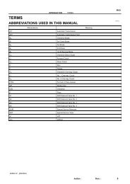
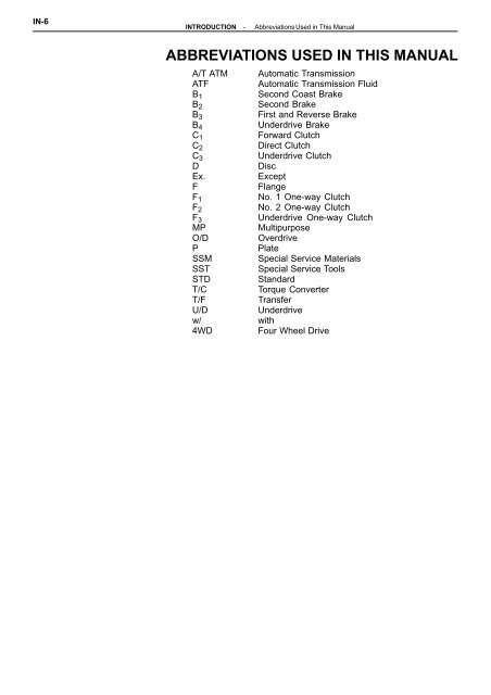
<strong>ABBREVIATIONS</strong> <strong>USED</strong> <strong>IN</strong> <strong>THIS</strong> <strong>MANUAL</strong><br />
A/T ATM Automatic Transmission<br />
ATF Automatic Transmission Fluid<br />
B1<br />
Second Coast Brake<br />
B2<br />
Second Brake<br />
B3<br />
First and Reverse Brake<br />
B4<br />
Underdrive Brake<br />
C1<br />
Forward Clutch<br />
C2<br />
Direct Clutch<br />
C3<br />
Underdrive Clutch<br />
D Disc<br />
Ex. Except<br />
F Flange<br />
F1<br />
No. 1 One-way Clutch<br />
F2<br />
No. 2 One-way Clutch<br />
F3<br />
Underdrive One-way Clutch<br />
MP Multipurpose<br />
O/D Overdrive<br />
P Plate<br />
SSM Special Service Materials<br />
SST Special Service Tools<br />
STD Standard<br />
T/C Torque Converter<br />
T/F Transfer<br />
U/D Underdrive<br />
w/ with<br />
4WD Four Wheel Drive
AX-2<br />
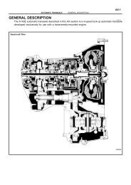
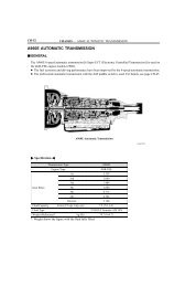
DESCRIPTION<br />
General<br />
A240L, A241E, A243L<br />
The A240L, A241E and A243L automatic transaxles are 4-speed transaxles with a lock-up mechanism<br />
developed exclusively for use with a transversely-mounted engine.<br />
The A241E automatic transaxle is an Electronically Controlled Transaxle (hereafter called ECT).<br />
These automatic transaxles have the following features.<br />
The “Super-Flow” torque converter is used to improve the transmission efficiency.<br />
When shifting the transmission, the engine torque is controlled and the clutch hydraulic<br />
pressure in the transmission is electronically controlled to reduce transmission shift shock.<br />
(A241E)<br />
Transaxle control ECU has been integrated with the Engine ECU. (A241E)<br />
These automatic transaxle are mainly composed of the torque converter with lock-up clutch, 4-speed<br />
planetary gear unit, the hydraulic control system and the electronic control system.<br />
To minimize the possibility of incorrect operation of the automatic transaxle, a shift lock mechanism has<br />
also been added.<br />
A240L<br />
AT4118<br />
AUTOMATIC TRANSAXLE - Description<br />
Torque Converter,<br />
4-Speed Gear Unit<br />
and Hydraulic Control System<br />
Differential
AT5715<br />
AT5716<br />
AUTOMATIC TRANSAXLE - Description<br />
A243L<br />
A241E<br />
AX-3
AX-4<br />
A241H<br />
The A241H automatic transaxle is a 4-speed automatic transaxle developed for full-time 4WD use.<br />
Its construction is that of the favorably received A240L automatic transaxle.<br />
In addition, a center differential control clutch, which operates in response to driving conditions, has been<br />
incorporated.<br />
The center differential control clutch controls excessive differences in the rotation rates of the front and<br />
rear wheels to provide the most suitable driving conditions.<br />
NOTICE: Special handling methods are necessary for full-time 4WD vehicles during inspection and<br />
maintenance. Instructions concerning these handling methods are given on Corolla Repair Manual<br />
(Pub. No. RM252U) on page <strong>IN</strong>-8.<br />
A241H<br />
AT4877<br />
Front Differential<br />
AUTOMATIC TRANSAXLE - Description<br />
Center Differential<br />
Control Clutch<br />
Torque Converter,<br />
4-Speed Gear Unit,<br />
and Hydraulic Control System<br />
Transfer<br />
Center Differential
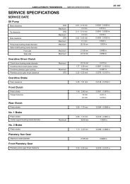
General Specifications<br />
Type of Transaxle A240L A243L A241E A241H<br />
Type of Engine 4A-FE 4A-FE 5S-FE 4A-FE<br />
Torque Converter<br />
Gear Ratio<br />
Number of Disc<br />
and Plates<br />
(Disc/Plate)<br />
Stall Torque Ratio 2.3 : 1 2.5 : 1 2.0 : 1 2.3 : 1<br />
Lock-Up Mechanism Equipped ← ← ←<br />
1st Gear 3.643 4.005 3.643 ←<br />
2nd Gear 2.008 2.208 2.008 ←<br />
3rd Gear 1.296 1.425 1.296 ←<br />
O/D Gear 0.892 0.981 0.892 ←<br />
Reverse Gear 2.977 3.272 2.977 ←<br />
C 1 Forward Clutch 4/4 ← ← ←<br />
C 2 Direct Clutch 2/3 2/3 3/3 2/3<br />
C 3 Underdrive clutch 3/3 3/3 3/5 3/3<br />
B 2 2nd Brake 3/3 ← ← ←<br />
B 3 1st and Reverse Brake 6/5 ← ← ←<br />
B 4 Underdrive Brake 3/3 ← ← ←<br />
B 1 Band Width mm (in.) 25 (0.98) ← ← ←<br />
ATF<br />
Transfer Oil<br />
Type<br />
Type<br />
AUTOMATIC TRANSAXLE - Description<br />
Capacity<br />
liter<br />
(US. qts, Imp. qts)<br />
Capacity<br />
liter<br />
(US. qts, Imp. qts)<br />
ATF<br />
DEXRONII ← ←<br />
7.2<br />
(7.6, 6.3)<br />
7.7<br />
(8.1, 6.8)<br />
8.0<br />
(8.5, 7.0)<br />
ATF Type T<br />
or equivalent<br />
8.2<br />
(8.7, 7.2)<br />
Transaxle Oil<br />
E50, API GL5,<br />
SAE 75W-90 or<br />
equivalent<br />
0.8<br />
(0.8, 0.7)<br />
AX-5
AX-6<br />
OPERATION<br />
Mechanical Operation<br />
OPERAT<strong>IN</strong>G CONDITIONS<br />
AT8498<br />
Range (i.e.,)<br />
Shift Lever<br />
Position<br />
2nd Brake (B2) One-W ay Clutch (F2) 1st & Reverse Brake (B 3)<br />
Gear<br />
No. 1<br />
Solenoid<br />
Valve *1<br />
One-W ay<br />
Clutch (F 1)<br />
U/D Planetary Gear Unit<br />
Front Planetary<br />
Gear Unit<br />
Forward Clutch (C1) 2nd Coast Brake (B1) Direct Clutch (C2) U/D Clutch (C 3)<br />
No. 2<br />
Solenoid<br />
Valve *1 C 1 C 2 C 3 B 1 B 2 B 3 B 4 F 1 F 2 F 2<br />
P Park ON OFF <br />
R Reverse ON OFF <br />
N Neutral ON OFF <br />
D<br />
2<br />
L<br />
U/D Brake (B 4)<br />
U/D One-Way Clutch (F 3)<br />
AUTOMATIC TRANSAXLE - Operation<br />
Rear Planetary<br />
Gear Unit<br />
1st ON OFF <br />
2nd ON ON <br />
3rd OFF ON <br />
O/D OFF OFF <br />
1st ON OFF <br />
2nd ON ON <br />
3rd *2 OFF ON <br />
1st ON OFF <br />
2nd *2 ON ON <br />
*1 : A241E only : Operating<br />
*2 : Down-Shift only in the the 3rd gear for the 2 range and 2nd gear for the L-range - no up-shift
FUNCTION OF COMPONENTS<br />
Component Function<br />
C 1 Forward Clutch Connects input shaft and front planetary ring gear.<br />
C 2 Direct Clutch Connects input shaft and front & rear planetary sun gear.<br />
C 3 U/D Clutch Connects underdrive sun gear and underdrive planetary carrier.<br />
B 1<br />
B 2<br />
2nd Coast Brake<br />
2nd Brake<br />
Prevents front & rear planetary sun gear from turning either clockwise or<br />
counterclockwise.<br />
Prevents outer race of F 1 from turning either clockwise or counterclockwise<br />
thus preventing the front & rear planetary sun gear from turning counterclockwise.<br />
B 3 1st & Reverse Brake Prevents rear planetary carrier from turning either clockwise or counterclockwise.<br />
B 4<br />
F 1<br />
U/D Brake<br />
No. 1 One-Way Clutch<br />
Prevents underdrive sun gear from turning either clockwise or counterclockwise.<br />
When B 2 is operating, this clutch prevents the front & rear planetary<br />
sun gear from turning counterclockwise.<br />
F 2 No. 2 One-Way Clutch Prevents rear planetary carrier from turning counterclockwise.<br />
F 3 U/D One-Way Clutch Prevents underdrive planetary sun gear from turning clockwise.<br />
Planetary Gears<br />
AT2690<br />
U/D Planetary Gear Unit<br />
AUTOMATIC TRANSAXLE - Operation<br />
These gears change the route through which driving force is transmitted in<br />
accordance with the operation of each clutch and brake in order to increase<br />
or reduce the input and output speed.<br />
Counter Shaft<br />
Front & Rear Sun Gear<br />
Rear Planetary<br />
Gear Unit<br />
Front Planetary<br />
Gear Unit<br />
Ring Gear<br />
Intermediate Shaft<br />
Input Shaft<br />
AX-7
AX-8<br />
FUNCTION OF COMPONENTS (Cont’d)<br />
The conditions of operation for each gear position are shown on the following illustration:<br />
D or 2 Range 1st Gear<br />
AT3216<br />
D Range 2nd Gear<br />
AT3217<br />
D Range 3rd Gear<br />
AT3218<br />
D Range O/D<br />
AT3219<br />
AUTOMATIC TRANSAXLE - Operation<br />
2 Range 2nd Gear<br />
AT3220<br />
L Range 1st Gear<br />
AT3221<br />
R Range Reverse Gear<br />
AT3222
Hydraulic Control System<br />
The hydraulic control system is composed of the oil pump, the valve body, the solenoid valves, the accumulators,<br />
the clutches and brakes, and the governor valve as well as the fluid passages which connect<br />
all of these components.<br />
Based on the hydraulic pressure created by the oil pump, the hydraulic control system governs the hydraulic<br />
pressure acting on the torque converter, clutches and brakes in accordance with the vehicle driving<br />
conditions.<br />
The governor valve produces hydraulic pressure in response to vehicle speed. Governor pressure increases<br />
as vehicle speed increases. (A240L and A243L)<br />
There are three solenoid valves on the valve body of the A241E automatic transaxle.<br />
The No. 1 and No. 2 solenoid valves are turned on and off by signals form the ECU to operate the shift<br />
valves and change the gear shift position.<br />
The No. 3 solenoid valve is operated by signals from the ECU to the engage or disengage the lock-up<br />
clutch of the torque converter.<br />
The valve body of the A240L and A243L automatic transaxle has one solenoid valve, which is for overdrive<br />
control.<br />
A241E<br />
HYDRAULIC CONTROL SYSTEM<br />
OIL PUMP<br />
Throttle Cable<br />
ECU<br />
A240L, A243L and A241H<br />
VALVE BODY<br />
Hydr. pressure control<br />
Fluid passage switching<br />
SOLENOID VALVES<br />
HYDRAULIC CONTROL SYSTEM<br />
VALVE BODY<br />
OIL PUMP Hydr. pressure control<br />
Throttle Cable<br />
AUTOMATIC TRANSAXLE - Operation<br />
Fluid passage switching<br />
O/D Main Switch SOLENOID VALVES<br />
CLUTCHES & BRAKES<br />
Governor Valve<br />
CLUTCHES & BRAKES<br />
Planetary gear unit<br />
Torque converter<br />
Planetary gear unit<br />
Torque converter<br />
AX-9
AX-10<br />
A241E Electronic Control System<br />
GENERAL<br />
The electronic control system for the A241E automatic transmission provides extremely precise control<br />
of the gear shift timing and lock-up timing in response to driving conditions as sensed by various sensors<br />
located throughout the vehicle and in response to the engine’s running condition.<br />
At the same time, the ECU control reduces vehicle squat when the vehicle starts out and gear shift<br />
shock. The electronic control system is also equipped with a self diagnosis system which diagnoses malfunctions<br />
of electronically controlled components and warns the driver, and a fail-safe system which<br />
makes it possible for the vehicle to continue functioning when a malfunction occurs.<br />
CONSTRUCTION<br />
The electronic control system can be broadly divided into three groups; the sensors, ECU and actuators.<br />
SENSORS Engine & ECT ECU ACTUATOR<br />
Throttle Position Sensor<br />
Idling Signal<br />
Throttle Position Signal<br />
Water Temperature Sensor<br />
Distributor<br />
Engine RPM Sensor<br />
Crankshaft Angle Signal<br />
No. 1 Speed Sensor<br />
No. 2 Speed Sensor<br />
SPD<br />
SP2 Transaxle<br />
Control of<br />
Shift Timing<br />
S1 No. 1 Solenoid<br />
Valve<br />
No. 2 Solenoid<br />
Pattern Select Switch<br />
P<br />
S2 Valve<br />
Neutral Start Switch<br />
Neutral Start Signal<br />
Shift Lever Position Signal<br />
O/D Main Switch<br />
Stop Light Switch<br />
Cruise Control ECU<br />
Battery<br />
AUTOMATIC TRANSAXLE - Operation<br />
IDL Engine<br />
VTA<br />
THW Ignition Timing<br />
Control<br />
IGt<br />
IGf<br />
Ne<br />
G 1, G-<br />
NSW<br />
2, L<br />
OD 2<br />
STP<br />
OD 1<br />
+B<br />
Control of<br />
Lock-Up Timing<br />
Self-Diagnostic<br />
System<br />
Back-Up System<br />
ESA<br />
Igniter<br />
Ignition Coil<br />
Distributor<br />
Spark Plugs<br />
SL Lock-Up Solenoid<br />
Valve<br />
OD 2<br />
O/D OFF<br />
Indicator Light<br />
Diagnostic<br />
Code Display
AX-102<br />
AT7927<br />
A241E<br />
A240L, A243L<br />
AT7901 AT7902<br />
AT7904 AT7903<br />
AUTOMATIC TRANSAXLE (A240L, A241E, A243L) - Component Parts (Valve Body)<br />
No. 1 Gasket<br />
No. 1 Gasket<br />
(Assembly of Valve Body)<br />
(See page AX-89 )<br />
1. POSITION PLATE AND NEW GASKETS ON LOWER<br />
VALVE BODY<br />
Position the new No. 2 gasket, the plate and then the<br />
new No. 1 gasket on the lower valve body.<br />
H<strong>IN</strong>T: Since the No. 1 gasket and No. 2 gasket are<br />
similar use the illustration below to discriminate between<br />
them.<br />
No. 2 Gasket<br />
No. 2 Gasket
AT7983<br />
A240L, A243L<br />
AT3055<br />
A241E<br />
AT2588<br />
A240L, A243L<br />
AT3048<br />
A243L<br />
Gasket<br />
Plate<br />
Gasket<br />
AT3047<br />
AUTOMATIC TRANSAXLE (A240L, A241E, A243L) - Component Parts (Valve Body)<br />
Strainer<br />
2. PLACE LOWER VALVE BODY WITH PLATE AND<br />
GASKETS ON UPPER VALVE BODY<br />
H<strong>IN</strong>T: Hold the lower valve body, gaskets and plate securely<br />
so they do not separate.<br />
Align each bolt hole in the valve bodies with the gaskets<br />
and plate.<br />
3. <strong>IN</strong>STALL AND F<strong>IN</strong>GER TIGHTEN BOLTS <strong>IN</strong> LOWER<br />
VALVE BODY TO SECURE UPPER VALVE BODY<br />
Install and finger tighten the five bolts. (A240L, A243L).<br />
H<strong>IN</strong>T: Each bolt length (mm) is indicated in the figure.<br />
Install: and finger tighten the nine bolts. (A241E)<br />
H<strong>IN</strong>T: Each bolt length (mm) is indicated in the figure.<br />
4. <strong>IN</strong>STALL LOWER VALVE BODY COVER<br />
(a) Install the strainer. (A240L, A243L Only)<br />
AX-103<br />
(b) Position a new gasket and plate and then another<br />
new gasket.
AX-104<br />
A241E<br />
AT8032<br />
A243L<br />
A240L<br />
AT3046<br />
A241E<br />
AT2546<br />
AT3058<br />
A240L, A243<br />
AT3059<br />
AUTOMATIC TRANSAXLE (A240L, A241E, A243L) - Component Parts (Valve Body)<br />
Gasket<br />
Plate<br />
Gasket<br />
(c) Position the lower valve body cover.<br />
(d) Install and finger tighten the seventeen bolts.<br />
(A240L, A243L)<br />
H<strong>IN</strong>T: Each bolt length (mm) is indicated in the figure.<br />
(e) Install and finger tighten the ten bolts.<br />
(A241E)<br />
H<strong>IN</strong>T: Each bolt length (mm) is indicated in the figure.<br />
5. <strong>IN</strong>STALL AND F<strong>IN</strong>GER TIGHTEN BOLTS <strong>IN</strong> UPPER<br />
VALVE BODY<br />
Install and finger tighten the eight bolts.<br />
H<strong>IN</strong>T: Each bolt length (mm) is indicated in the figure.<br />
6. TIGHTEN BOLTS OF UPPER AND LOWER VALVE<br />
BODIES<br />
(a) Tighten the twenty-two bolts in the lower valve<br />
body.<br />
(A240L, A243L)<br />
Torque: 6.4 N-m (65 kgf-cm, 56 in.-lbf)
A241E<br />
AT5725<br />
AT3058<br />
AT7793<br />
A240L,<br />
A243L<br />
AT3138<br />
A241E<br />
AT5724<br />
AUTOMATIC TRANSAXLE (A240L, A241E, A243L) - Component Parts (Valve Body)<br />
(b) Tighten the nineteen bolts in the lower valve body.<br />
(A241E)<br />
Torque: 6.4 N-m (65 kgf-cm, 56 in.-lbf)<br />
(c) Tighten the eight bolts in the upper valve body.<br />
Torque: 6.4 N-m (65 kgf-cm, 56 in.-lbf)<br />
7. <strong>IN</strong>STALL SOLENOID<br />
(a) Install the new O-rings on the each solenoids.<br />
(b) Install the solenoids.<br />
H<strong>IN</strong>T: Each bolt length (mm) is indicated in the figure.<br />
Torque: 6.4 N-m (kgf-cm, 56 in.-lbf)<br />
Torque: A 6.4 N-m (65 kgf-cm, 56 in.-lbf)<br />
B 10 N-m (100 kgf-cm, 7 ft-lbf)<br />
AX-105
AX-106<br />
N-m (kgf-cm, ft-lbf)<br />
♦ Non-reusable part<br />
AUTOMATIC TRANSAXLE (A240L, A241E, A243L) - Component Parts (Differential)<br />
♦ Oil Seal<br />
(For Transaxle Housing)<br />
Differential Pinion Shaft<br />
Differential Case<br />
Outer Race<br />
Adjusting Shim<br />
: Specified torque<br />
Pin<br />
Adjusting Shim<br />
Outer Race<br />
Side Bearing<br />
Differential<br />
COMPONENTS<br />
Speedometer<br />
Drive Gear<br />
Side Bearing<br />
97 (985, 71)<br />
Pinion Thrust Washer<br />
Differential Pinion<br />
Side Gear Thrust Washer<br />
Differential Side Gear<br />
Ring Gear<br />
♦ Locking Plate<br />
♦ Oil Seal<br />
(For Transaxle Case)<br />
AT8013
AT5731<br />
TA0016<br />
AT8087<br />
AT7984<br />
SST<br />
AT8062<br />
AUTOMATIC TRANSAXLE (A240L, A241E, A243L) - Component Parts (Differential)<br />
Matchmarks<br />
DISASSEMBLY OF DIFFERENTIAL<br />
1. REMOVE R<strong>IN</strong>G GEAR<br />
(a) Place the matchmarks on the ring gear and differential<br />
case.<br />
(b) Loosen the staked part of the locking plate.<br />
AX-107<br />
(c) Remove the eight bolts and four locking plates.<br />
(d) Using a plastic hammer, tap on the ring gear to<br />
remove it from the case.<br />
2. REMOVE SIDE BEAR<strong>IN</strong>GS FROM DIFFERENTIAL<br />
CASE<br />
(a) Setting SST to the cut-out portion on the<br />
speedometer drive gear, remove the bearing from<br />
the differential case.<br />
SST 09502-10012<br />
(b) Remove the speedometer drive gear.
AX-108<br />
SST<br />
AT8061<br />
AT8078<br />
AT8059<br />
Pinion<br />
Side<br />
Gear<br />
AT2980<br />
AT7923<br />
AUTOMATIC TRANSAXLE (A240L, A241E, A243L) - Component Parts (Differential)<br />
Pinion Shaft<br />
Thrust Washer<br />
(c) Setting SST to the cut-out portion on the differential<br />
case, remove the bearing.<br />
SST 09502-10012<br />
3. DISASSEMBLY DIFFERENTIAL CASE<br />
(a) Drive out the pinion shaft lock pin from the ring<br />
gear side.<br />
(b) Remove the pinion shaft from the case.<br />
(c) Remove the two pinions, two side gears and four<br />
thrust washers.<br />
4. REMOVE OIL SEAL OF TRANSAXLE HOUS<strong>IN</strong>G<br />
Using a screwdriver, remove the oil seal.
AT8487<br />
AT8486<br />
AT8479<br />
AT8002<br />
AT8003<br />
AUTOMATIC TRANSAXLE (A240L, A241E, A243L) - Component Parts (Differential)<br />
SST<br />
SST<br />
5. REMOVE SIDE BEAR<strong>IN</strong>G OUTER RACE OF TRANS-<br />
AXLE HOUS<strong>IN</strong>G<br />
Using SST and a hammer, drive out the outer race and<br />
shim.<br />
SST 09350-32014 (09351-32090)<br />
6. REMOVE OIL SEAL OF TRANSAXLE CASE<br />
Using a screwdriver, remove the oil seal.<br />
7. REMOVE SIDE BEAR<strong>IN</strong>G OUTER RACE OF TRANS-<br />
AXLE CASE<br />
Using SST and a hammer, drive out the outer race and<br />
adjusting shim.<br />
SST 09350-32014 (09351-32130, 09351-32150)<br />
ASSEMBLY OF DIFFERENTIAL<br />
AX-109<br />
1. <strong>IN</strong>STALL SIDE BEAR<strong>IN</strong>G OUTER RACE OF TRANS-<br />
AXLE HOUS<strong>IN</strong>G<br />
(a) Place the shim onto the transaxle housing.<br />
(b) Using SST and press, press a new outer race<br />
into the transaxle housing.<br />
SST 09350-32014 (09351-32111, 09351-32130)<br />
2. <strong>IN</strong>STALL SIDE BEAR<strong>IN</strong>G OUTER RACE OF TRANS-<br />
AXLE CASE<br />
(a) Place the adjusting shim onto the transaxle case.<br />
(b) Using SST and press, press a new outer race<br />
into the transaxle case.<br />
SST 09350-32014 (09351-32111, 09351-32130)
AX-1 10<br />
AT8497<br />
AT2980<br />
AT8058<br />
AT2981<br />
AUTOMATIC TRANSAXLE (A240L, A241E, A243L) - Component Parts (Differential)<br />
3. ASSEMBLY DIFFERENTIAL CASE<br />
(a) Install the thrust washers to the side gears.<br />
(b) Install the side gears with thrust washers, pinion<br />
gears pinion thrust washers into the differential<br />
case.<br />
(c) Install the pinion shaft so as to align the lock pin<br />
holes on the pinion shaft and differential case.<br />
4. CHECK SIDE GEAR BACKLASH<br />
(a) Measure the side gear backlash while holding one<br />
pinion gear toward the case.<br />
Standard backlash: 0.05 - 0.20 mm<br />
(0.0020 - 0.0079 in.)<br />
If the backlash is out of specification, install the correct<br />
thrust washer to the side gear.<br />
(b) Referring to the table below, select thrust washers<br />
which will ensure that the backlash is within specification.<br />
Try to select washers of the same size of<br />
both sides.<br />
Thickness<br />
0.95 (0.0374)<br />
1.00 (0.0394)<br />
1.05 (0.0413)<br />
Thrust washer thicknesses<br />
mm (in.) Thickness mm (in.)<br />
1.10 (0.0433)<br />
1.15 (0.0453)<br />
1.20 (0.0472)<br />
If the backlash is not within specification, install a thrust<br />
washer of a different thickness.
AT8093<br />
AT8075<br />
AT5833<br />
AT2982<br />
AT8044<br />
AUTOMATIC TRANSAXLE (A240L, A241E, A243L) - Component Parts (Differential)<br />
5. <strong>IN</strong>STALL LOCK P<strong>IN</strong><br />
(a) Using a hammer and punch, drive the lock pin<br />
through the case and hole in the pinion shaft.<br />
(b) Stake the differential case.<br />
AX-1 11<br />
6. <strong>IN</strong>STALL SIDE BEAR<strong>IN</strong>GS TO DIFFERENTIAL CASE<br />
(a) Using SST and press, press the side bearing into<br />
the differential case.<br />
SST 09710-30030 (09710-03160)<br />
(b) Install the speedometer drive gear to the differential<br />
case.<br />
(c) Using SST and press, press the side bearing into<br />
the differential case.<br />
SST 09350-32014 (09351-32090, 09351-32120)
AX-1 12<br />
AT8484<br />
AT8485<br />
AT5831<br />
AT7886<br />
AUTOMATIC TRANSAXLE (A240L, A241E, A243L) - Component Parts (Differential)<br />
Seal<br />
Packing<br />
SST<br />
7. ADJUST SIDE BEAR<strong>IN</strong>G PRELOAD<br />
(a) Remove any packing material and be careful not<br />
to get oil on the contacting surfaces of the transaxle<br />
housing or transmission case.<br />
(b) Install the differential to the transaxle case.<br />
(c) Install the transaxle housing to the transaxle case.<br />
(d) Install and tighten the bolts.<br />
Torque: 29 N-m (300 kgf-cm, 22 ft-lbf)<br />
H<strong>IN</strong>T: Each bolt length (mm) is indicated in the illustration.<br />
(e) Using SST, rotate the differential in both directions<br />
to snug the bearing down.<br />
SST 09563-3201 1<br />
(f) Using SST and a torque meter, measure the preload<br />
of the side bearing.<br />
SST 09564-3201 1<br />
Preload (at starting):<br />
New bearing 0.8-1.4 N-m<br />
(8-14 kgf-cm, 6.9-12.2 in.-lbf)<br />
Used bearing 0.4-0.7 N-m<br />
(4-7 kgf-cm, 3.5-6.1 in.-lbf)<br />
If the preload is not within specification, remove the differential<br />
from the transaxle case. Re-select the transaxle<br />
case side adjusting shim.<br />
Thickness<br />
2.00 (0.0787) 2.20 (0.0866) 2.40 (0.0945) 2.60 (0.1024) 2.80 (0.1102)<br />
2.05 (0.0807) 2.25 (0.0886) 2.45 (0.0965) 2.65 (0.1043) 2.85 (0.1122)<br />
2.10 (0.0827) 2.30 (0.0906) 2.50 (0.0984) 2.70 (0.1063) 2.90 (0.1142)<br />
2.15 (0.0846) 2.35 (0.0925) 2.55 (0.1004) 2.75 (0.1083)<br />
mm (in.)<br />
H<strong>IN</strong>T: The preload will change about 0.3 - 0.4 N-m (3 -<br />
4 kgf-cm, 2.6 - 3.5 in.-lbf) with each shim thickness.
TA0074<br />
AT8485<br />
MT0089<br />
AT2780<br />
TA0019<br />
AUTOMATIC TRANSAXLE (A240L, A241E, A243L) - Component Parts (Differential)<br />
Case Side<br />
(g) Remove the bolts and transaxle housing.<br />
(h) Remove the differential from the transaxle case.<br />
8. <strong>IN</strong>STALL R<strong>IN</strong>G GEAR To DIFFERENTIAL<br />
AX-1 13<br />
(a) Clean the contact surface of the differential case.<br />
(b) Heat the ring gear to about 100°C (212°F) in an<br />
oil bath.<br />
NOTICE: Do not heat the ring gear above 110°C<br />
(230°F).<br />
(c) Clean the contact surface of the ring gear with<br />
cleaning solvent.<br />
(d) Quickly install the ring gear on the differential<br />
case.<br />
(e) Install new locking bolts uniformly and a little at a<br />
time. Torque the bolts.<br />
Torque: 97 N-m (985 kgf-cm, 71 ft-lbf)<br />
(f) Using a hammer and drift punch, stake the locking<br />
plates.<br />
H<strong>IN</strong>T: Stake one claw with the flat surface of the nut.<br />
For the claw contacting the protruding portion of the<br />
nut, stake only the half on the tightened side.
AX-1 14<br />
AT8005<br />
AT8004<br />
AUTOMATIC TRANSAXLE (A240L, A241E, A243L) - Component Parts (Differential)<br />
9. <strong>IN</strong>STALL OIL SEAL OF TRANSAXLE CASE<br />
(a) Using SST and a hammer, drive in a new oil seal.<br />
SST 09350-32014 (09351-32130, 09351-32111)<br />
(b) Coat the lip of the seal with MP grease.<br />
10. <strong>IN</strong>STALL OIL SEAL OF TRANSAXLE HOUS<strong>IN</strong>G<br />
(a) Using SST and a hammer, drive in a new oil seal.<br />
SST 09350-32014 (09351-32130, 09351-32150)<br />
(b) Coat the lip of oil seal with MP grease.
AUTOMATIC TRANSAXLE (A240L, A241E, A243L) - Installation of Component Parts<br />
AX-1 15<br />
<strong>IN</strong>STALLATION OF COMPONENT PARTS<br />
(See pages AX-16 to AX-21 )<br />
Disassembly, inspection and assembly of each component group have been indicated in the preceding<br />
chapter. Before assembly, make sure again that all component groups are assembled correctly.<br />
If something wrong is found in a certain component group during assembly, inspect and repair this group<br />
immediately.<br />
Recommended ATF: DEXRON II<br />
GENERAL NOTES:<br />
1. The automatic transmission is composed of highly precision-finished parts, necessitating<br />
careful inspection before assembly because even a small nick could case fluid leakage or<br />
affect performance.<br />
2. Before assembling new clutch discs, soak them in automatic transmission fluid for at least<br />
fifteen minutes.<br />
3. Apply automatic transmission fluid on sliding or rotating surfaces of parts before assembly.<br />
4. Use petroleum jelly to keep small parts in their place.<br />
5. Do not use adhesive cements on gaskets and similar parts.<br />
6. When assembling the transmission, sure to use new gaskets and O-rings.<br />
7. Dry all parts with compressed air-never use shop rags.
AX-1 16<br />
8. Be sure to install the thrust bearings and races in the correct direction and position.<br />
AT2955<br />
AUTOMATIC TRANSAXLE (A240L, A241E, A243L) - Installation of Component Parts
Front<br />
Bearing<br />
Race<br />
Thrust<br />
Bearing<br />
Rear<br />
Bearing<br />
Race<br />
AT3065<br />
AT2915<br />
AT2913<br />
AUTOMATIC TRANSAXLE (A240L, A241E, A243L) - Installation of Component Parts<br />
Outer<br />
Diameter<br />
Inner<br />
Diameter<br />
Outer<br />
Diameter<br />
Inner<br />
Diameter<br />
Outer<br />
Diameter<br />
Inner<br />
Diameter<br />
A241E<br />
A243L<br />
A240L<br />
A241E<br />
A243L<br />
A240L<br />
A B C D E F G H<br />
37.3<br />
(1.469)<br />
24.1<br />
(0.949)<br />
37.6<br />
(1.480)<br />
37.6<br />
1.4801<br />
24.0<br />
(0.945)<br />
24.0<br />
(0.945)<br />
37.6<br />
(1.480)<br />
22.2<br />
(0.874)<br />
SST<br />
45.0<br />
(1.772)<br />
28.0<br />
(1.102)<br />
45.0<br />
(1.772)<br />
45.0<br />
11.7721<br />
30.0<br />
(1.181)<br />
30.0<br />
(1.181)<br />
-<br />
-<br />
37.9<br />
(1.492) ←<br />
22.0<br />
(0.866) ←<br />
36.1<br />
(1.421) ←<br />
36.1<br />
(1.421) ←<br />
22.2<br />
(0.874) ←<br />
22.2<br />
(0.874) ←<br />
35.0<br />
11.3781<br />
19.0<br />
(0.748)<br />
35.7<br />
(1.406)<br />
23.0<br />
(0.906)<br />
43.0<br />
(1.693)<br />
30.5<br />
(1.201)<br />
42.0<br />
(1.654)<br />
42.0<br />
(1.654)<br />
28.9<br />
(1.138)<br />
28.9<br />
(1.138)<br />
42.0<br />
(1.654)<br />
27.1<br />
(1.067)<br />
57.7<br />
(2.272)<br />
57.7<br />
(2.272)<br />
41.0<br />
(1.614)<br />
41.0<br />
(1.614)<br />
45.2<br />
(1.780)<br />
41.8<br />
(1.646)<br />
30.0<br />
(1.181)<br />
43.7<br />
(1.720)<br />
45.2<br />
(1.780) ←<br />
31.0<br />
(1.220)<br />
mm (in.)<br />
←<br />
31.0<br />
(1.220) ←<br />
- - -<br />
- - -<br />
1. <strong>IN</strong>STALL BEAR<strong>IN</strong>G To TRANSAXLE HOUS<strong>IN</strong>G<br />
(a) Using SST and a press, press the bearing into<br />
the transaxle housing.<br />
SST 09350-32014 (09351-32140)<br />
(b) Install the bearing stopper with a bolt.<br />
AX-1 17<br />
2. <strong>IN</strong>STALL NEW GASKET AND OIL TUBE APPLY<br />
COVER<br />
Install the new gasket and oil tube apply cover, and<br />
tighten the three bolts.
AX-1 18<br />
AT2956<br />
AT2911<br />
AT0593<br />
AT2910<br />
Q00980<br />
AUTOMATIC TRANSAXLE (A240L, A241E, A243L) - Installation of Component Parts<br />
A240L, A243L<br />
Only<br />
SST<br />
3. <strong>IN</strong>STALL OIL TUBES<br />
(a) Using a plastic hammer, install the three (A241E)<br />
or four (A240L, A243L) oil tubes.<br />
NOTICE: Be careful not to bend or damage the tubes.<br />
(b) Install the flour tube clamps.<br />
4. <strong>IN</strong>STALL BEAR<strong>IN</strong>G TO TRANSMISSION CASE<br />
Using SST and a press, press the bearing into the<br />
transmission case.<br />
SST 09350-32014 (09351-32090)<br />
5. <strong>IN</strong>STALL B4 ACCUMULATOR PISTON AND SPR<strong>IN</strong>G<br />
6. <strong>IN</strong>STALL OIL GALLERY COVER AND GASKET<br />
(a) Clean the threads of the screws and case with<br />
white gasoline.<br />
(b) Install the new gasket and oil gallery cover in<br />
place.<br />
(c) Install and tighten the three bolts.
Q00981<br />
AT0548<br />
AT0547<br />
AT2959<br />
AT0545<br />
AUTOMATIC TRANSAXLE (A240L, A241E, A243L) - Installation of Component Parts<br />
(d) Apply seal packing or equivalent to the six screws.<br />
Seal packing: Part No. 08833 - 00070, THREE BOND<br />
1324 or equivalent<br />
(e) Using a torx wrench, install and tighten the three<br />
screws.<br />
7. <strong>IN</strong>STALL <strong>MANUAL</strong> VALVE SHAFT AND LEVER<br />
(a) Install the parking lock rod to the manual valve<br />
lever.<br />
(b) Slide in the shaft and install the washer, new<br />
spacer and manual lever.<br />
AX-1 19<br />
(c) Install the retaining spring.<br />
H<strong>IN</strong>T: Make sure there is a washer between the retaining<br />
spring and case.<br />
8. <strong>IN</strong>STALL P<strong>IN</strong><br />
(a) Using a pin punch and hammer, drive in the pin.<br />
(b) Position the spacer and stake it.<br />
9. <strong>IN</strong>STALL CAM GUIDE BRACKET<br />
Install the cam guide bracket and then install the parking<br />
lock rod into the guide bracket.
AX-120<br />
AT0544<br />
AT0700<br />
AT0701<br />
AT7931<br />
AT7890<br />
AUTOMATIC TRANSAXLE (A240L, A241E, A243L) - Installation of Component Parts<br />
Clamp Groove<br />
10. <strong>IN</strong>STALL PARK<strong>IN</strong>G LOCK SLEEVE<br />
Install the parking lock sleeve protruding portion upward.<br />
11. PLACE STOPPER PLATE<br />
Place the stopper plate on the protruding portion of<br />
lock sleeve.<br />
12. <strong>IN</strong>STALL GUIDE SLEEVE AND SPR<strong>IN</strong>G<br />
13. <strong>IN</strong>STALL PARK<strong>IN</strong>G LOCK PAWL, PAWL SHAFT AND<br />
SHAFT CLAMP<br />
(a) Install the parking lock pawl.<br />
(b) Insert the parking lock pawl shaft and install the<br />
shaft clamp.
AT2962<br />
AT2963<br />
AT8483<br />
AT2888<br />
AT2960<br />
AUTOMATIC TRANSAXLE (A240L, A241E, A243L) - Installation of Component Parts<br />
SST<br />
SST<br />
SST<br />
14. <strong>IN</strong>STALL FIRST AND REVERSE BRAKE PISTON<br />
(a) Install the two new O-rings to the piston.<br />
(b) Coat the O-rings with ATF.<br />
(c) Place the piston into the bore of the case, facing<br />
the spring seats upward.<br />
(d) Using SST, press in the piston.<br />
SST 09350-32014 (09351-32040)<br />
H<strong>IN</strong>T: Be careful not to damage the O-rings.<br />
(e) Remove SST.<br />
15. <strong>IN</strong>STALL PISTON RETURN SPR<strong>IN</strong>G AND SNAP<br />
R<strong>IN</strong>G<br />
(a) Install the piston return spring assembly and snap<br />
ring in place.<br />
(b) Set SST, and tighten the bolt gradually to compress<br />
the springs.<br />
SST 09350-32014 (09351-32040)<br />
NOTICE: Avoid bending the spring retainer by overtightening<br />
the bolt.<br />
(c) Using snap ring pliers, install the snap ring.<br />
H<strong>IN</strong>T: Visually check to make sure it is fully seated and<br />
centered by the three lugs on the spring retainer.<br />
Be sure the end gap of snap ring is not aligned with the<br />
sprig retainer claw.<br />
(d) Remove SST.<br />
SST 09350-32014 (09351-32040)<br />
16. <strong>IN</strong>STALL UNDERDRIVE BRAKE PISTON<br />
(a) Coat the O-rings with ATF.<br />
(b) Install the two new O-rings to the piston.<br />
AX-121
AX-122<br />
AT2961<br />
AT2901<br />
AT2900<br />
AT2899<br />
AT7889<br />
SST<br />
AUTOMATIC TRANSAXLE (A240L, A241E, A243L) - Installation of Component Parts<br />
(c) Place the piston into the case with the cup side<br />
up, being careful not to damage the O-rings.<br />
17. <strong>IN</strong>STALL RETURN SPR<strong>IN</strong>G<br />
18. <strong>IN</strong>STALL PLATES, DISCS AND FLANGE<br />
(a) Install in order: D = Disc P = Plate F = Flange<br />
P-D-P-D-P-D-F<br />
H<strong>IN</strong>T: Install the Flange with the flat end facing downward.<br />
(b) Place SST on the flange, and compress the<br />
flange with a press.<br />
SST 09350-3201 (09351-32070)<br />
(c) Install the snap ring.<br />
H<strong>IN</strong>T: Be sure the end gap of the snap ring is not<br />
aligned with one of the cutouts.<br />
19. CONFIRM THAT UNDERDRIVE BRAKE PISTON<br />
MOVES<br />
Using compressed air, confirm that the underdrive<br />
brake piston moves smoothly.
AT2898<br />
AT1292<br />
AT1289<br />
AT0597<br />
AT7987<br />
Free<br />
AUTOMATIC TRANSAXLE (A240L, A241E, A243L) - Installation of Component Parts<br />
Lock<br />
17.3 - 18.2 mm<br />
20. <strong>IN</strong>STALL OIL SEAL R<strong>IN</strong>GS TO TRANSMISSION<br />
CASE<br />
Install the two oil seals to the transmission case.<br />
21. <strong>IN</strong>STALL UNDERDRIVE ONE-WAY CLUTCH<br />
AX-123<br />
22. <strong>IN</strong>STALL ANTI-RATTLE CLIP<br />
In the place shown in the figure (the space between the<br />
one-way clutch outer race and case), push the antirattle<br />
clip in until you hear the ”click”.<br />
23. <strong>IN</strong>STALL UNDERDRIVE CLUTCH ASSEMBLY<br />
(a) Align the flukes of discs in the underdrive brake.<br />
(b) Install the clutch assembly.<br />
(c) Turn the clutch assembly. The clutch assembly<br />
should turn freely counterclockwise and should<br />
lock clockwise.<br />
24. CHECK HEIGHT OF CLUTCH ASSEMBLY<br />
Using vernier calipers, check the height from the sleeve<br />
to the inner race.<br />
Height: 17.3 - 18.2 mm (0.681 - 0.717 in.)
AX-124<br />
AT8482<br />
AT7999<br />
AT1293<br />
AT1294<br />
AT2896<br />
AUTOMATIC TRANSAXLE (A240L, A241E, A243L) - Installation of Component Parts<br />
SST<br />
25. CHECK PISTON STROKE OF UNDERDRIVE<br />
CLUTCH<br />
(a) Set a dial indicator (long type pick or SST) as<br />
shown.<br />
SST 09350-32014 (09351-32190)<br />
(b) Applying and releasing the compressed air (392 -<br />
785 kPa, 4 - 8 kg/cm 2 , 57 - 114 psi), measure the<br />
underdrive clutch piston stroke.<br />
Piston stroke:<br />
A240L 1.50 - 1.86 mm (0.0591 - 0.0732 in.)<br />
A241E, A243L<br />
1.21 - 1.55 mm (0.0476 - 0.0610 in.)<br />
If the piston stroke is less than limit, parts may have been<br />
misassembled. Check them.<br />
If the piston stroke is nonstandard, select another flange.<br />
H<strong>IN</strong>T: There are two different flange thickness.<br />
Flange thicknesses:<br />
A240L 2.04 mm (0.0803 in.)<br />
2.40 mm (0.0945 in.)<br />
A241E, A243L 2.30 mm (0.0906 in.)<br />
2.50 mm (0.0984 in.)<br />
2.70 mm (0.1063 in.)<br />
26. <strong>IN</strong>STALL BEAR<strong>IN</strong>G WITH RAGE<br />
Install the thrust bearing with race, with the bearing facing<br />
upward.<br />
Bearing A240L<br />
A241E,<br />
A243L<br />
Outer diameter 43.7 (1.720) 45.2 (1.780)<br />
Inner diameter 31.0 (1.220) 31.0 (1.220)<br />
mm (in.)<br />
27. <strong>IN</strong>STALL SUN GEAR To CASE<br />
Install the sun gear of the counter shaft to the case.<br />
28. <strong>IN</strong>STALL COUNTER SHAFT ASSEMBLY<br />
(a) Align the flukes of the discs in the underdrive<br />
clutch.<br />
(b) Install the counter shaft assembly.
AT0601<br />
AT0533<br />
AT8084<br />
SST<br />
AT0603<br />
AT0076<br />
AUTOMATIC TRANSAXLE (A240L, A241E, A243L) - Installation of Component Parts<br />
SST<br />
29. CHECK HEIGHT OF COUNTER SHAFT<br />
Using vernier calipers, measure the distance between<br />
the tip of the counter shaft and bolt seat of the clutch<br />
support.<br />
Height: 33.3 - 35.5 mm (1.311 - 1.398 in.)<br />
30. <strong>IN</strong>STALL THRUST NEEDLE BEAR<strong>IN</strong>G<br />
Bearing: Outer diameter 57.7 mm (2.272 in.)<br />
Inner diameter 41.0 mm (1.614 in.)<br />
31. <strong>IN</strong>STALL COUNTER DRIVEN GEAR<br />
Using SST and press, press in the driven gear.<br />
SST 09350-32014 (09351-32100, 09351-32140)<br />
32. TIGHTEN NEW LOCK NUT<br />
(a) Using SST to hold the driven gear, tighten a new<br />
lock nut.<br />
SST 09330-00021 and 09350-32014 (09351-32032)<br />
Torque: 157 N-m (1,600 kgf-cm, 116 ft-lbf)<br />
(b) Remove SST.<br />
33. CHECK END PLAY OF COUNTER SHAFT<br />
Using a dial indicator, measure the end play of the<br />
counter shaft.<br />
End play: 0.23 - 0.89 mm (0.0091 - 0.0360 in.)<br />
AX-125
AX-126<br />
AT0604<br />
AT0523<br />
AT2892<br />
AT8034<br />
AT8039<br />
AUTOMATIC TRANSAXLE (A240L, A241E, A243L) - Installation of Component Parts<br />
Seal Packing<br />
34. STAKE LOCK NUT<br />
Using a punch and hammer, stake the lock nut.<br />
35. <strong>IN</strong>STALL SNAP R<strong>IN</strong>G To TRANSMISSION CASE<br />
Using snap ring pliers, install the snap ring to the transmission<br />
case.<br />
36. <strong>IN</strong>STALL <strong>IN</strong>TERMEDIATE SHAFT<br />
37. <strong>IN</strong>STALL TRANSAXLE REAR COVER<br />
(a) Remove any packing material and be careful not to<br />
get oil on the contacting surfaces of the transaxle<br />
rear cover or transmission case.<br />
(b) Apply seal packing to the rear cover as shown.<br />
Seal packing: Part No. 08833 - 00090, THREE BOND<br />
1131, LOCTITE 518 or equivalent.<br />
(c) Install and tighten the thirteen bolts.<br />
Torque: 29 N-m (300 kgf-cm, 22 ft-lbf)<br />
H<strong>IN</strong>T: Each bolt length (mm) is indicated in the figure.
A241E<br />
AT5602<br />
A240L, A243L<br />
AT2893<br />
AT0527<br />
AT0526<br />
AT0606<br />
AUTOMATIC TRANSAXLE (A240L, A241E, A243L) - Installation of Component Parts<br />
38. <strong>IN</strong>STALL NEW APPLY GASKETS<br />
Install the two (A241E) or three (A240L, A243L) new<br />
apply gaskets.<br />
H<strong>IN</strong>T: The oil seal may be inserted with either end up or<br />
down.<br />
39. <strong>IN</strong>STALL GOVERNOR DRIVEN GEAR<br />
(a) Install the thrust washer.<br />
(b) Install the governor driven gear.<br />
AX-127<br />
40. CHECK <strong>IN</strong>TERMEDIATE SHAFT<br />
Make sure that the intermediate shaft turns smoothly.
AX-128<br />
AT0607<br />
AT5829<br />
AT3139<br />
AT0610<br />
AT7892<br />
AUTOMATIC TRANSAXLE (A240L, A241E, A243L) - Installation of Component Parts<br />
41. <strong>IN</strong>STALL DISCS, PLATES AND FLANGE<br />
(a) Install the inner flange, facing the flat end upward.<br />
(b) Install in order: D = Disc P = Plate<br />
D-P-D-P-D-P-D-P-D-P-D<br />
(c) Install the outer flange, the flat end facing downward.<br />
42. <strong>IN</strong>STALL SNAP R<strong>IN</strong>G<br />
H<strong>IN</strong>T: Be sure the snap ring end gap is not aligned with<br />
one of the cutouts.<br />
43. CONFIRM THAT FIRST AND REVERSE BRAKE PIS-<br />
TON MOVES<br />
Using compressed air, confirm that the first and reverse<br />
brake piston moves smoothly.
AT8086<br />
AT0612<br />
AT0613<br />
AT0323<br />
AT0614<br />
AUTOMATIC TRANSAXLE (A240L, A241E, A243L) - Installation of Component Parts<br />
Align<br />
44. <strong>IN</strong>STALL REAR PLANETARY R<strong>IN</strong>G GEAR TO CASE<br />
(a) Coat the races and bearing with petroleum jelly,<br />
and install them onto the ring gear as shown.<br />
Bearing and races:<br />
mm (in.)<br />
Outer diameter Inner diameter<br />
Front Race 37.3 (1.4699) 24.1 (0.949)<br />
Bearing 37.6 (1.480) 24.0 (0.945)<br />
Rear Race 37.6 (1.480) 22.0 (0.874)<br />
(b) Using a screwdriver, align the flukes of the discs.<br />
(c) Install the rear planetary ring gear into the case.<br />
45. <strong>IN</strong>STALL REAR PLANETARY GEAR<br />
AX-129<br />
(a) Coat the thrust washer with petroleum jelly and<br />
install it onto the planetary gear.<br />
H<strong>IN</strong>T: Make sure that the different lug shapes match<br />
the openings on the gear.<br />
(b) Align the spline of the planetary gear with the<br />
flukes of the discs and install the planetary gear<br />
into the first and reverse brake discs.
AX-130<br />
AT5704<br />
AT2965<br />
AT2966<br />
AT0798<br />
AT0618<br />
Lock<br />
A<br />
Flange<br />
AUTOMATIC TRANSAXLE (A240L, A241E, A243L) - Installation of Component Parts<br />
Rear<br />
Planetary<br />
Gear<br />
SST<br />
Thrust Washer<br />
Free<br />
(c) Check that part A of the rear planetary gear is<br />
below the upper surface of the flange.<br />
46. <strong>IN</strong>STALL NO. 2 ONE-WAY CLUTCH<br />
(a) Place the one-way clutch into the case, the shiny<br />
side facing upward.<br />
(b) Install the one-way clutch onto the inner race<br />
while turning the planetary gear clockwise with<br />
SST.<br />
SST 09350-32014 (09351-32050)<br />
(c) Check that the planetary gear turns freely clockwise<br />
and locks counterclockwise.<br />
(d) Coat the thrust washer with petroleum jelly and<br />
install it onto the planetary gear.<br />
47. <strong>IN</strong>STALL SNAP R<strong>IN</strong>G<br />
Be sure the end gap of the snap ring is not aligned with<br />
one of the cutouts.<br />
48. <strong>IN</strong>STALL SECOND BRAKE <strong>IN</strong>TO CASE<br />
(a) Install the flange, the flat side facing upward.
AT2967<br />
AT0620<br />
AT7990<br />
AT0621<br />
AT0622<br />
AUTOMATIC TRANSAXLE (A240L, A241E, A243L) - Installation of Component Parts<br />
(b) Install the discs and plates in order.<br />
D = Disc P = Plate<br />
D-P-D-P-D-P<br />
AX-131<br />
49. <strong>IN</strong>STALL SECOND BRAKE PISTON RETURN<br />
SPR<strong>IN</strong>G<br />
Install each of the springs over the protrusions in the<br />
case.<br />
50. <strong>IN</strong>STALL SECOND COAST BRAKE BAND GUIDE<br />
Install the band guide so that its tip touches the case.<br />
51. <strong>IN</strong>STALL SECOND BRAKE DRUM <strong>IN</strong>TO CASE<br />
Align the groove of the drum with the bolt and place it<br />
into the case.<br />
52. <strong>IN</strong>STALL SNAP R<strong>IN</strong>G<br />
(a) Place the snap ring into the case so that the end<br />
gap is installed into the groove.<br />
(b) While compressing the piston return springs over<br />
the drum with hammer handles, install the snap<br />
ring.<br />
H<strong>IN</strong>T: Be sure the end gap of the snap ring is not<br />
aligned with one of the cutouts.
AX-132<br />
AT2592<br />
AT7891<br />
AT0626<br />
AT0627<br />
AT8088<br />
AUTOMATIC TRANSAXLE (A240L, A241E, A243L) - Installation of Component Parts<br />
53. <strong>IN</strong>STALL SECOND BRAKE DRUM GASKET<br />
Driven in a new drum gasket until it makes contact with<br />
the second brake drum.<br />
54. CONFIRM THAT SECOND BRAKE PISTON MOVES<br />
Using compressed air, confirm that the second brake<br />
piston moves smoothly.<br />
55. <strong>IN</strong>STALL SECOND BRAKE HUB NO. 1 ONE-WAY<br />
CLUTCH<br />
(a) Using a screwdriver, align the flukes of the discs<br />
in the second brake.<br />
(b) Align the spline of the hub with the flukes of the<br />
discs and install the hub to the second brake discs.<br />
56. CHECK SECOND BRAKE HUB <strong>IN</strong>STALLATION DIS-<br />
TANCE<br />
Check the distance between the surface of the second<br />
brake hub and rear planetary gear.<br />
Distance: Approx. 5 mm (0.20 in.)
AT8056<br />
AT0628<br />
AT2759<br />
AT0631<br />
AT2593<br />
AUTOMATIC TRANSAXLE (A240L, A241E, A243L) - Installation of Component Parts<br />
Baring<br />
Race<br />
Front Race<br />
Rear Race<br />
57. <strong>IN</strong>STALL SUN GAR AND SUN GEAR <strong>IN</strong>PUT DRUM<br />
(a) Coat the thrust washer with petroleum jelly and<br />
install it on the sun gear input drum.<br />
(b) While turning the sun gear clockwise, install it into<br />
the No. 1 one-way clutch.<br />
58. <strong>IN</strong>STALL FRONT PLANETARY GEAR<br />
(a) Coat the race and bearing with petroleum jelly<br />
and install them onto the planetary gear.<br />
Bearing and races:<br />
mm (in.)<br />
Outer diameter Inner diameter<br />
Bearing 45.0 (1.772) 30.0 (1.181)<br />
Race 45.0 (1.772) 28.0 (1.102)<br />
(b) Install the planetary gear.<br />
59. <strong>IN</strong>STALL FRONT PLANETARY R<strong>IN</strong>G GEAR<br />
(a) Coat the races and bearing with petroleum jelly<br />
and install them onto the planetary ring gear.<br />
Bearing and races:<br />
mm (in.)<br />
Outer diameter Inner diameter<br />
Front Race 37.9 (1.492) 22.0 (0.866)<br />
Bearing 36.1 (1.421) 22.2 (0.874)<br />
Rear Race 35.0 (1.378) 19.0 (0.748)<br />
AX-133
AX-134<br />
AT2968<br />
AT2023<br />
AT2969<br />
AT0635<br />
AT2970<br />
AUTOMATIC TRANSAXLE (A240L, A241E, A243L) - Installation of Component Parts<br />
Front Race<br />
Rear Race<br />
(b) Install the ring gear.<br />
H<strong>IN</strong>T: If the planetary ring gear and the other parts are<br />
installed correctly into the case, the end of the bushing<br />
with the ring gear flange will be flush with a shoulder of<br />
the intermediate shaft or under.<br />
(c) Coat the races and bearing with petroleum jelly and<br />
install them onto the tip of ring gear flange as shown.<br />
Bearing and races: mm (in.)<br />
Outer diameter Inner diameter<br />
Front Race 37.9 (1.492) 22.0 (0.866)<br />
Bearing 36.1 (1.421) 22.2 (0.874)<br />
Rear Race 35.7 (1.406) 23.0 (0.906)<br />
60. <strong>IN</strong>STALL SECOND COAST BRAKE BAND<br />
(a) Place the band into the case.<br />
(b) Install the pin through the oil pump mounting bolt<br />
hole.<br />
61. <strong>IN</strong>STALL FORWARD CLUTCH AND DIRECT CLUTCH<br />
(a) Coat the race and bearing with petroleum jelly,<br />
and install them onto the forward clutch drum.<br />
Bearing and race:<br />
mm (in.)<br />
Outer diameter Inner diameter<br />
Bearing 42.0 (1.654) 28.9 (1.138)<br />
Race 42.0 (1.654) 27.1 (1.067)
AT0349<br />
AT0350<br />
AT1984 AT0381<br />
AT2971<br />
AT2595<br />
AUTOMATIC TRANSAXLE (A240L, A241E, A243L) - Installation of Component Parts<br />
Thrust Washer<br />
Bushing<br />
AX-135<br />
(b) Coat the clutch drum thrust washer with petroleum<br />
jelly, and install it onto the direct clutch drum with<br />
the oil groove facing upward.<br />
(c) Using a screwdriver, align the flukes of discs in<br />
the direct clutch.<br />
(d) Mesh the hub with the flukes of the direct clutch<br />
while turning the clutch drum or forward clutch.<br />
H<strong>IN</strong>T: If the flukes of the discs are meshed with the hub<br />
correctly, the end of the bushing with the direct clutch<br />
drum will be flush with the surfaces of the forward<br />
clutch.<br />
(e) Place the direct clutch and forward clutch into the<br />
case.<br />
(f) While rotating the forward clutch to mesh the front<br />
planetary ring gear and discs, install them.<br />
(g) Check the distance between A and B shown in<br />
the illustration.<br />
Distance: Approx. 3 mm (0.118 in.)
AX-136<br />
AT0525<br />
AT8484<br />
AT5711<br />
AT2766<br />
AT2972<br />
AUTOMATIC TRANSAXLE (A240L, A241E, A243L) - Installation of Component Parts<br />
Seal<br />
Packing<br />
Sealant<br />
62. <strong>IN</strong>STALL DIFFERENTIAL<br />
63. <strong>IN</strong>STALL TRANSAXLE HOUS<strong>IN</strong>G<br />
(a) Remove any packing material and be careful not to<br />
get oil on the contacting surfaces of the transaxle<br />
housing or transmission case.<br />
(b) Apply seal packing to the transaxle housing as<br />
shown.<br />
Seal packing: Part No. 08833 - 00090, THREE BOND<br />
1131, LOCTITE 518 or equivalent.<br />
(c) Apply sealant to the bolt threads.<br />
Sealant: Part No. 08833 - 00080, Adhesive 1344,<br />
THREE BOND 1344, LOCTITE 242 or equivalent<br />
(d) Install and tighten the bolts.<br />
Torque: 29 N-m (300 kgf-cm, 22 ft-lbf)<br />
H<strong>IN</strong>T: Each bolt length (mm) is indicated in the illustration.<br />
64. CHECK PRELOAD OF DIFFERENTIAL SIDE BEAR<strong>IN</strong>G<br />
(See page AX-1 12)<br />
65. <strong>IN</strong>STALL OIL PUMP <strong>IN</strong>TO CASE<br />
(a) Coat the race with petroleum jelly and install it<br />
onto the stator shaft.<br />
Race: Outer diameter 43.0 mm (1.693 in.)<br />
Inner diameter 30.5 mm (1.201 in.)<br />
(b) Coat the new O-ring with ATF, and install it to<br />
pump body.
AT2973<br />
AT0637<br />
AT0638<br />
AT2974<br />
AT2870<br />
AUTOMATIC TRANSAXLE (A240L, A241E, A243L) - Installation of Component Parts<br />
O-Rings<br />
(c) Place the oil pump through the input shaft, and<br />
align the bolt holes of the pump body with the<br />
transmission case.<br />
(d) Hold the input shaft, and lightly press the oil pump<br />
body to slide the oil seal rings on the stator shaft<br />
through the direct clutch drum.<br />
NOTICE: Do not push on the oil pump strongly, or the<br />
oil seal ring will stick to the direct clutch drum.<br />
(e) Install and tighten the six bolts.<br />
Torque: 25 N-m (250 kgf-cm, 18 ft-lbf)<br />
66. MEASURE THRUST PLAY OF <strong>IN</strong>PUT SHAFT<br />
Measure the thrust play in axial direction.<br />
Thrust play: 0.3 - 0.9 mm (0.012 - 0.035 in.)<br />
If the play is not as specified, select and replace the<br />
race for the end of stator shaft.<br />
H<strong>IN</strong>T: There are two different thickness of races. If necessary,<br />
select one of them.<br />
Race thickness: 0.8 mm (0.031 in.)<br />
1.4 mm (0.055 in.)<br />
67. CHECK <strong>IN</strong>PUT SHAFT ROTATION<br />
Make sure that the input shaft rotates smoothly.<br />
68. <strong>IN</strong>STALL SECOND COAST BRAKE PISTON<br />
(a) Install the two new O-rings to the cover.<br />
H<strong>IN</strong>T: Coat the O-rings with ATF before installing.<br />
AX-137
AX-138<br />
AT2869<br />
AT2867<br />
AT2865<br />
AT8302<br />
SST<br />
AUTOMATIC TRANSAXLE (A240L, A241E, A243L) - Installation of Component Parts<br />
SST<br />
(b) Install the spring, piston and cover into the bore.<br />
(c) Using SST, install the snap ring while pressing<br />
the cover.<br />
SST 09350-31014 (09351-32050)<br />
(d) Check that the front end of the piston rod contacts<br />
the center of the second brake band depression.<br />
69. MEASURE PISTON STROKE OF SECOND COAST<br />
BRAKE<br />
(a) Apply a small amount of paint to the piston rod at<br />
the point it meets the case as shown in the illustration.<br />
(b) Using SST, measure the piston stroke applying<br />
and releasing the compressed air (392 - 785 kPa,<br />
4 - 8 kg/cm 2 , 57 - 114 psi) as shown.<br />
SST 09240-00020<br />
Piston stroke: 1.5 - 3.0 mm (0.059 - 0.118 in.)<br />
If it is still more than standard value, replace the brake<br />
band with a new one.<br />
70. <strong>IN</strong>STAL ACCUMULATOR PISTONS AND SPR<strong>IN</strong>GS<br />
(a) Coat the new O-rings with ATF, and install them<br />
to the pistons.
A241E<br />
A243L<br />
Inner<br />
Outer<br />
AT5703<br />
A241E, A243L<br />
AT5706<br />
A240L<br />
AT3225<br />
A240L<br />
AT3036<br />
No. 2<br />
No. 1<br />
No. 1 Spring<br />
(B 2)<br />
AUTOMATIC TRANSAXLE (A240L, A241E, A243L) - Installation of Component Parts<br />
Cover<br />
Outer<br />
Inner<br />
Gasket-<br />
Outer<br />
Inner<br />
(b) Install the pistons and springs to the case.<br />
(A241E)<br />
C 1<br />
C 2<br />
B 2<br />
C 3<br />
(A243L)<br />
C 1<br />
C 2<br />
Spring Free length mm (in.) Color<br />
Outer 74.1 (2.917) Pink<br />
Inner 41.0 (1.614) Pink<br />
No. 1 15.5 (0.610) Pink<br />
No. 2 62.54 (2.462) Pink<br />
No. 1 15.5 (0.610) Green<br />
No. 2 64.5 (2.539) Green<br />
Outer 65.2 (2.570) Blue<br />
Inner 48.0 (1.890) Orange<br />
Spring Free length mm (in.) Color<br />
Outer 77.8 (3.063) None<br />
Inner 42.5 (1.673) None<br />
71.54 (2.817)<br />
Blue and<br />
Light Blue<br />
B 2 56.68 (2.231) Yellow<br />
C 3 61.47 (2.420) White<br />
(A240L)<br />
C 1<br />
Spring Free length mm (in.) Color<br />
Outer 77.8 (3.063) None<br />
Inner 42.50 (1.6732) None<br />
C 2 64.8 (2.551) Yellow<br />
B 2<br />
No. 1 35.18 (1.3850) Yellow<br />
No. 2 56.68 (2.2315) Yellow<br />
AX-139<br />
C 3 64.72 (2.5480) Red and Yellow<br />
(c) Place the cover with a new gasket and gradually<br />
tighten the bolts little a time in sequence.<br />
Torque: 10 N-m (100 kgf-cm, 7 ft-lbf)
AX-140<br />
AT5707<br />
AT0643<br />
AT5692<br />
AT7991<br />
AT5616<br />
AUTOMATIC TRANSAXLE (A240L, A241E, A243L) - Installation of Component Parts<br />
71. <strong>IN</strong>STALL SECOND BRAKE APPLY GASKET<br />
72. <strong>IN</strong>STALL THROTTLE CABLE <strong>IN</strong> CASE<br />
Push the cable through the hole on the case, being<br />
careful not to damage the O-ring. Check for full seating.<br />
NOTICE: In subsequent work, to avoid breaking the<br />
cable fitting do not roll the case over the cable.<br />
73. <strong>IN</strong>STALL SOLENOID WIRE<br />
74. <strong>IN</strong>STALL VALVE BODY<br />
(a) Coat the manual valve with ATF and install it to<br />
the valve body.<br />
(b) Connect the connecting rod to the manual valve<br />
lever.
AT0108<br />
A241E<br />
AT3146<br />
A240L, A243L<br />
AT3146<br />
A243L<br />
A240L<br />
AT3135<br />
A241E<br />
AT2584<br />
AUTOMATIC TRANSAXLE (A240L, A241E, A243L) - Installation of Component Parts<br />
-Wire Retainer<br />
Wire<br />
Retainer<br />
(c) Place the valve body on the transmission.<br />
(d) While holding the cam down with your hand, slip<br />
the cable end into the slot.<br />
(e) Install the twelve bolts and wire retainer shown in<br />
the illustration, and hand tighten all the bolts first.<br />
Then tighten them with a torque wrench.<br />
H<strong>IN</strong>T: Each bolt length (mm) is indicated in the illustration.<br />
Torque: 10 N-m (100 kgf-cm, 7 ft-lbf)<br />
75. CONNECT SOLENOID CONNECTOR<br />
H<strong>IN</strong>T: Wire color<br />
White<br />
Black<br />
Yellow<br />
AX-141
AX-142<br />
AT5685<br />
AT2975<br />
AT2855<br />
AT2854<br />
AT2853<br />
AUTOMATIC TRANSAXLE (A240L, A241E, A243L) - Installation of Component Parts<br />
Gasket<br />
76. <strong>IN</strong>STALL <strong>MANUAL</strong> DETENT SPR<strong>IN</strong>G<br />
(a) Install the detent spring and cover in place, and<br />
install the bolt (length: 16 mm).<br />
(b) Hand tighten the bolt first, then tighten the bolt<br />
with a torque wrench.<br />
Torque: 10 N-m (100 kgf-cm, 7 ft-lbf)<br />
(c) Check that the manual valve lever is in contact<br />
with the center of the roller at the tip of the detent<br />
spring.<br />
77. <strong>IN</strong>STALL OIL TUBES<br />
(a) Tap the tubes with a plastic hammer to install<br />
them into the positions indicated in the illustration.<br />
NOTICE: Be careful not to bend or damaged the tubes.<br />
(b) Install the oil tube clamp and bracket.<br />
H<strong>IN</strong>T: Each bolt length (mm) is indicated in the illustration.<br />
Hand tighten ail bolts first, then tighten them with a<br />
torque wrench.<br />
Torque: 10 N-m (100 kgf-cm, 7 ft-lbf)<br />
78. <strong>IN</strong>STALL OIL STRA<strong>IN</strong>ER<br />
(a) Install the new gasket to the oil strainer.<br />
(b) Install the oil strainer with the three bolts.<br />
H<strong>IN</strong>T: each bolt length (mm) is indicated in the illustration.
AT2976<br />
AT7992<br />
AT7919<br />
AT2852<br />
AT7932<br />
AUTOMATIC TRANSAXLE (A240L, A241E, A243L) - Installation of Component Parts<br />
79. <strong>IN</strong>STALL THREE MAGNETS <strong>IN</strong> OIL PAN<br />
NOTICE: Make sure that the magnets do not interfere<br />
with the oil tubes.<br />
80. <strong>IN</strong>STALL OIL PAN<br />
(a) Install a new gasket to the oil pan and install them<br />
to the transmission.<br />
(b) Tighten the eighteen bolts.<br />
Torque: 4.9 N-m (50 kgf-cm, 43 in.-lbf)<br />
(c) Install a new gasket to the drain plug and install it<br />
to the oil pan.<br />
Torque: 17 N-m (175 kgf-cm, 13 ft-lbf)<br />
81. (A241E)<br />
<strong>IN</strong>STALL SPEED SENSOR AND SENSOR ROTOR<br />
(a) Install the sensor adaptor with three bolts.<br />
(b) Install the sensor rotor.<br />
AX-143
AX-144<br />
AT5684<br />
AT7926<br />
AT7887<br />
AT5683<br />
AT2852<br />
AUTOMATIC TRANSAXLE (A240L, A241E, A243L) - Installation of Component Parts<br />
(c) Install a new O-ring to the sensor cover.<br />
(d) Install the sensor cover to the transmission and<br />
then install the sensor cover bracket with the two<br />
bolts.<br />
Torque: 13 N-m (130 kgf-cm, 9 ft-lbf)<br />
(e) Coat a new O-ring with ATF and install it to the<br />
speed sensor.<br />
(f) Install the speed sensor and retaining plate.<br />
Torque: 10 N-m (100 kgf-cm, 7 ft-lbf)<br />
82. (A240L, A241E, A243L)<br />
<strong>IN</strong>STALL GOVERNOR BODY<br />
(a) Install the governor oil strainer to the case.<br />
(b) Install a new gasket to governor body adaptor.<br />
(c) Install the governor body adaptor with three bolts.
AT2851<br />
AT2850<br />
AT2848<br />
AT5652<br />
AT5641<br />
AUTOMATIC TRANSAXLE (A240L, A241E, A243L) - Installation of Component Parts<br />
Thrust Washer<br />
O-Rings<br />
(d) Install the governor body and thrust washer.<br />
(e) Install a new O-ring to the cover.<br />
(f) Install the cover to the transmission and then<br />
install the two cover brackets with the two<br />
bolts.<br />
Torque: 13 N-m (130 kgf-cm, 9 ft-lbf)<br />
83. <strong>IN</strong>STALL SOLENOID WIRE RETA<strong>IN</strong><strong>IN</strong>G PLATE<br />
Install the retaining plate with the bolt.<br />
84. <strong>IN</strong>STALL THROTTLE CABLE RETA<strong>IN</strong><strong>IN</strong>G PLATE<br />
Install the retaining plate with the bolt.<br />
AX-145
AX-146<br />
AT5639<br />
AT5730<br />
AT7762<br />
AT5638<br />
AT5637<br />
AUTOMATIC TRANSAXLE (A240L, A241E, A243L) - Installation of Component Parts<br />
Neutral<br />
Basic<br />
Line<br />
Groove<br />
85. <strong>IN</strong>STALL NEUTRAL START SWITCH<br />
(a) Install the neutral start switch to the manual valve<br />
shaft.<br />
(b) Install the packing. (A240L, A241E)<br />
(c) Install the nut and lock stopper.<br />
(d) Tighten the nut.<br />
Torque: 6.9 N-m (70 kgf-cm, 61 in.-lbf)<br />
(e) Temporarily install the manual shift lever.<br />
(f) Turn the lever counterclockwise until it stops, then<br />
turn it clockwise two notches.<br />
(g) Remove the manual shift lever.<br />
(h) Align the groove and neutral basic line as shown.<br />
(i) Install and tighten the two bolts.<br />
Torque: 5.4 N-m (55 kgf-cm, 48 in.-lbf)<br />
(j) Using a screwdriver, stake the nut with the nut<br />
stopper.<br />
(k) Install the manual shift lever with the washer, and<br />
tighten the nut.<br />
86. <strong>IN</strong>STALL FILLER TUBE AND TRANSMISSION DIP-<br />
STICK<br />
87. <strong>IN</strong>STALL TWO OIL COOLER PIPES
Adapter Plug<br />
Throttle Cable<br />
Strainer 7.4 (75, 65 in.-lbf)<br />
Governor Body<br />
♦ Gasket<br />
Thrust Washer<br />
♦ O-Ring<br />
♦ O-Ring<br />
Hose<br />
Plug<br />
Governor<br />
Cover<br />
Parking Rod<br />
Manual Valve Lever<br />
Manual Valve Lever Shaft<br />
Plate Washer<br />
Neutral Start Switch<br />
Manual Valve<br />
♦ Gasket<br />
N-m (kgf-cm, ft-lbf)<br />
♦ Non-reusable part<br />
Valve Body<br />
♦ Gasket<br />
AUTOMATIC TRANSAXLE (A241H) - Removal of Component Parts<br />
Pin<br />
Spring<br />
Drain Plug<br />
♦ Oil Seal<br />
: Specified torque<br />
REMOVAL OF COMPONENT PARTS<br />
(A241H)<br />
COMPONENTS<br />
Magnet<br />
♦ Gasket<br />
♦ Gasket<br />
♦ O-Ring<br />
130 (130, 9)<br />
Oil Pressure Switch<br />
Union Elbow<br />
27 (275, 20)<br />
Plate<br />
7.4 (75, 65 in.-lbf)<br />
Spring<br />
Second Coast<br />
Brake Piston<br />
Cover<br />
♦ Gasket<br />
Oil Tube<br />
Bracket<br />
Solenoid<br />
Wire<br />
♦ O-Ring<br />
Snap Ring<br />
Stopper<br />
Manual Shift<br />
Lever<br />
6.9 (70, 61 in.-lbf) 130 (130, 9) ♦ O-Ring<br />
Detent Spring<br />
Spring<br />
Spring Plate ♦ O-Ring<br />
Clamp<br />
Piston<br />
Spring<br />
Oil Strainer<br />
Clamp<br />
Oil Pan<br />
Cover<br />
AX-147<br />
AT3367
AX-148<br />
22 (225, 16)<br />
Snap<br />
Ring<br />
Disc<br />
Snap Ring<br />
N-m (kgf-cm, ft-lbf)<br />
♦ Non-reusable part<br />
Oil Pump<br />
Bearing<br />
Front Planetary<br />
Ring Gear<br />
Race<br />
Piston Return<br />
Spring<br />
Flange<br />
♦ O-Ring<br />
Plate<br />
Second Brake<br />
Piston<br />
AUTOMATIC TRANSAXLE (A241H) - Removal of Component Parts<br />
Plate<br />
Race<br />
: Specified torque<br />
Race<br />
Disc<br />
Direct Clutch<br />
Front Planetary<br />
Gear<br />
COMPONENTS (Cont’d)<br />
Thrust Washer<br />
Flange<br />
Flange<br />
Race<br />
Bearing<br />
Bearing<br />
Planetary Sun Gear<br />
One-W ay<br />
Clutch No. 2<br />
Snap Ring<br />
Snap Ring<br />
Thrust Washer<br />
Rear Planetary<br />
Gear<br />
Thrust Washer<br />
Forward Clutch<br />
One-W ay Clutch<br />
Intermediate Shaft<br />
Second Brake<br />
Drum Seal<br />
25 (250, 18)<br />
Second Brake Apply Gasket<br />
Second Coast<br />
Brake Band Guide<br />
Pin<br />
Bearing<br />
Race<br />
Race<br />
Second Coast<br />
Brake Band<br />
Bearing<br />
Rear Planetary<br />
Ring Gear<br />
Transaxle<br />
Rear Cover<br />
AT3368
♦ Nut<br />
Transfer Assembly<br />
♦ Gasket<br />
Governor Driven Gear<br />
See page AX-151<br />
Parking Lock<br />
Shaft<br />
Drain Plug<br />
Apply Gasket<br />
Thrust Washer<br />
Differential Side Gear<br />
Intermediate Shaft<br />
AUTOMATIC TRANSAXLE (A241H) - Removal of Component Parts<br />
Under Drive Input Shaft with<br />
Planetary Gear<br />
♦ Snap Ring<br />
♦ Gasket<br />
29 (300, 22)<br />
Parking Lock<br />
Lever<br />
♦ Oil Seal Ring<br />
Clamp<br />
COMPONENTS (Cont’d)<br />
Bearing<br />
Under Drive Clutch<br />
Differential<br />
Retainer<br />
♦ O-Ring<br />
29 (300, 22)<br />
Bearing<br />
Oil Seal<br />
Ring<br />
Oil Tube<br />
Plate<br />
♦ Gasket<br />
♦ Apply Gasket<br />
Thrust Washer<br />
Spring<br />
Spring Guide<br />
Plate<br />
♦ Apply Gasket<br />
N-m (kgf-cm, ft-lbf)<br />
♦ Non-reusable part<br />
Precoated part<br />
: Specified torque<br />
13 (130, 9)<br />
Transaxle Housing<br />
Cover<br />
Plate<br />
Under Drive<br />
One-W ay Clutch<br />
Retainer<br />
♦ Bearing<br />
Plate<br />
Clamp<br />
Counter Driven<br />
Gear<br />
Sleeve<br />
Clamp<br />
AX-149<br />
157 (1,600, 116)<br />
AT3366
AX-150<br />
AT8074<br />
AT8069<br />
AT8496<br />
AT8079<br />
AT8042<br />
SST<br />
AUTOMATIC TRANSAXLE (A241H) - Removal of Component Parts<br />
SEPARATE BASIC SUBASSEMBLY<br />
1. REMOVE TRANSFER ASSEMBLY<br />
(a) Remove six nuts.<br />
(b) Using a plastic hammer, remove the transfer assembly<br />
from the transaxle.<br />
2. REMOVE DIFFERENTIAL SIDE GEAR <strong>IN</strong>TERMEDI-<br />
ATE SHAFT<br />
(a) Screw in suitable bolt with washer into the side<br />
gear intermediate shaft.<br />
(b) Using SST, remove the side gear intermediate<br />
shaft.<br />
SST 09520-32012<br />
3. REMOVE <strong>MANUAL</strong> SHIFT LEVER<br />
Remove the nut, washer and manual shift lever.<br />
4. REMOVE NEUTRAL START SWITCH<br />
(a) Using a screwdriver, unstake the nut stopper.<br />
(b) Remove the nut, nut stopper and packing.
AT8043<br />
AT0501<br />
AT0502<br />
AT8053<br />
AT8045<br />
AUTOMATIC TRANSAXLE (A241H) - Removal of Component Parts<br />
(c) Remove the two bolts and neutral start switch.<br />
5. REMOVE THROTTLE CABLE RETA<strong>IN</strong><strong>IN</strong>G PLATE<br />
Remove the bolt and plate.<br />
6. REMOVE SOLENOID WIRE RETA<strong>IN</strong><strong>IN</strong>G PLATE<br />
Remove the bolt and plate.<br />
7. REMOVE GOVERNOR BODY<br />
(a) Remove the two bolts and cover brackets.<br />
AX-151<br />
(b) Using a screwdriver, remove the governor cover.<br />
H<strong>IN</strong>T: Tape the screwdriver tip before use so as not to<br />
damage the cover of transaxle.
AX-152<br />
AT2850<br />
AT8071<br />
AT8051<br />
AT8057<br />
AT0102<br />
AUTOMATIC TRANSAXLE (A241H) - Removal of Component Parts<br />
O-Ring<br />
(c) Remove the O-ring from the cover.<br />
(d) Remove the governor body with thrust washer.<br />
(e) Remove the three bolts and governor body adaptor<br />
with gasket.<br />
(f) Remove the governor oil strainer.<br />
8. REMOVE PAN AND GASKET<br />
(a) Remove the eighteen bolts.<br />
(b) Remove the pan by lifting the transmission case.<br />
NOTICE: Do not turn the transmission over as it will<br />
contaminate the valve body with the foreign materials<br />
in the bottom of the pan.<br />
(c) Remove the gasket.<br />
(d) Place the transmission on wooden blocks to prevent<br />
damage to the pipe.
AT0103<br />
AT3449<br />
AT2854<br />
AT3428<br />
AT3432<br />
AUTOMATIC TRANSAXLE (A241H) - Removal of Component Parts<br />
9. EXAM<strong>IN</strong>E PARTICLES <strong>IN</strong> PAN<br />
Remove the magnets and use them to collect any steel<br />
chips. Look carefully at the chips and particles in the<br />
pan and on the magnet to anticipate what type of wear<br />
you will find in the transmission:<br />
Steel (magnetic) . . . . . . . bearing, gear and plate wear<br />
Brass (non-magnetic) . . bushing wear<br />
10. TURN TRANSMISSION OVER<br />
11. REMOVE OIL STRA<strong>IN</strong>ER<br />
(a) Remove the three bolts and oil strainer.<br />
(b) Remove the gasket.<br />
12. REMOVE OIL TUBES<br />
(a) Remove the two bolts and tube bracket.<br />
AX-153<br />
(b) Remove the tube clamp bolt and clamp.<br />
(c) Pry up both tube ends with a large screwdriver<br />
and remove the five tubes.
AX-154<br />
AT0653<br />
AT3135<br />
AT3433<br />
AT0108<br />
AT0507<br />
AUTOMATIC TRANSAXLE (A241H) - Removal of Component Parts<br />
13. REMOVE <strong>MANUAL</strong> DETENT SPR<strong>IN</strong>G<br />
14. DISCONNECT SOLENOID CONNECTOR<br />
15. REMOVE VALVE BODY<br />
(a) Remove the twelve bolts and wire retainer as<br />
shown.<br />
(b) Disconnect the throttle cable from the cam.<br />
(c) While disconnecting the manual valve connecting<br />
rod from the manual valve lever, remove the valve<br />
body.<br />
16. REMOVE THROTTLE CABLE FROM CASE<br />
Pull out the throttle cable.
AT3114<br />
AT1290<br />
AT2860<br />
A12861<br />
AT3036<br />
No. 1 Spring<br />
(B 2)<br />
AUTOMATIC TRANSAXLE (A241H) - Removal of Component Parts<br />
17. REMOVE SOLENOID WIRE<br />
18. REMOVE SECOND BRAKE APPLY GASKET<br />
AX-155<br />
19. REMOVE C3 ACCUMULATOR PISTON AND SPR<strong>IN</strong>G<br />
Using low-pressure compressed air (98 kPa, 1 kg/cm 2 ,<br />
14 psi), pop out the piston into a rag. Force air into the<br />
hole shown and remove the piston and spring.<br />
20. REMOVE ACCUMULATOR PISTONS AND SPR<strong>IN</strong>GS<br />
(a) Loosen the five bolts one turn at a time until the<br />
spring tension is released.<br />
(b) Remove the cover, gasket and spring on the B2<br />
piston.
AX-156<br />
AT3111<br />
AT2863<br />
AT3141<br />
AT2865<br />
AT2866<br />
AUTOMATIC TRANSAXLE (A241H) - Removal of Component Parts<br />
SST<br />
(c) Remove the C1 piston and two springs.<br />
(d) Using low-pressure compressed air (98 kPa, 1<br />
kg/cm 2 , 14 psi), pop out the C2 piston into a rag.<br />
Force air into the hole shown and remove the<br />
piston and spring.<br />
(e) Using low-pressure compressed air (98 kPa, 1<br />
kg/cm 2 , 14 psi), pop out the B2 piston into a rag.<br />
Force air into the hole shown and remove the piston<br />
and spring.<br />
21. MEASURE PISTON STROKE OF SECOND COAST<br />
BRAKE<br />
(a) Apply a small amount of paint to the piston rod at<br />
the point it meets the case as shown in the illustration.<br />
(b) Using SST, measure the piston stroke applying<br />
and releasing the compressed air (392 - 785 kPa,<br />
4 - 8 kg/cm 2 , 57 - 114 psi) as shown.<br />
SST 09240-00020<br />
Piston stroke: 1.5 - 3.0 mm (0.059 - 0.118 in.)<br />
If the piston stroke exceed the limit, inspect the brake<br />
band.
AT2867<br />
AT2868<br />
AT2869<br />
AT2870<br />
AT8070<br />
SST<br />
SST<br />
AUTOMATIC TRANSAXLE (A241H) - Removal of Component Parts<br />
22. REMOVE SECOND COAST BRAKE PISTON<br />
(a) Using SST, remove the snap ring.<br />
SST 09350-32014 (09351-32050)<br />
(b) Using low-pressure compressed air (98 kPa, 1<br />
kg/cm 2 , 14 psi), pop out the cover into a rag.<br />
Force air into the hole shown.<br />
(c) Remove the cover, piston and spring.<br />
(d) Remove the two O-rings from the<br />
cover.<br />
23. REMOVE OIL PUMP<br />
AX-157<br />
(a) Remove the six bolts holding the oil pump to the<br />
transmission case.<br />
(b) Using SST, remove the oil pump.<br />
SST 09350-32014 (09351-32061)<br />
NOTICE: Be careful not to drop or damage the races<br />
and bearing behind oil pump.<br />
(c) Remove SST from the oil pump:
AX-158<br />
A<br />
AT0352<br />
AT3035<br />
AT8049<br />
AT0651<br />
AT0652<br />
AUTOMATIC TRANSAXLE (A241H) - Removal of Component Parts<br />
(d) Remove the race from the oil pump.<br />
(e) Remove the O-ring from the oil pump.<br />
24. REMOVE OIL SEAL R<strong>IN</strong>GS<br />
Remove the two oil seal rings.<br />
25. REMOVE DIRECT CLUTCH<br />
26. REMOVE FORWARD CLUTCH<br />
(a) Remove the forward clutch with bearing and race.
AT2873<br />
AT3461<br />
AT2875<br />
AT0515<br />
AT2876<br />
AUTOMATIC TRANSAXLE (A241H) - Removal of Component Parts<br />
(b) Remove the thrust washer, bearing and races from<br />
the forward clutch.<br />
27. REMOVE SECOND COAST BRAKE BAND<br />
(a) Push the pin with a small screwdriver and remove<br />
it from the bolt hole of the oil pump mounting.<br />
(b) Remove the brake band.<br />
28. REMOVE FRONT PLANETARY R<strong>IN</strong>G GEAR<br />
(a) Remove the front planetary ring gear with bearing<br />
and race.<br />
(b) Remove the bearing and race from the ring gear.<br />
29. REMOVE FRONT PLANETARY GEAR<br />
(a) Remove the front planetary gear with race.<br />
AX-159
AX-160<br />
AT2877<br />
AT2878<br />
AT0518<br />
AT7891<br />
AT0519<br />
AUTOMATIC TRANSAXLE (A241H) - Removal of Component Parts<br />
(b) Remove the races and bearing from the planetary<br />
gear or sun gear.<br />
30. REMOVE SUN GEAR, SUN GEAR <strong>IN</strong>PUT DRUM AND<br />
THRUST WASHER<br />
31. REMOVE SECOND BRAKE HUB AND NO. 1 ONE-<br />
WAY CLUTCH<br />
32. CONFIRM THAT SECOND BRAKE PISTON MOVES<br />
Using compressed air, confirm that the second brake<br />
piston moves smoothly.<br />
33. REMOVE SECOND COAST BRAKE BAND GUIDE
AT2879<br />
AT2880<br />
AT2859<br />
AT2881<br />
AT2882<br />
AUTOMATIC TRANSAXLE (A241H) - Removal of Component Parts<br />
34. REMOVE SNAP R<strong>IN</strong>G HOLD<strong>IN</strong>G SECOND BRAKE<br />
DRUM TO CASE<br />
35. REMOVE SECOND BRAKE DRUM<br />
H<strong>IN</strong>T: If the brake drum is difficult to remove, lightly tap<br />
it with a wooden block.<br />
36. REMOVE SECOND BRAKE DRUM SEAL<br />
Using a needle nose pliers, pull out the second brake<br />
drum seal.<br />
37. REMOVE SECOND BRAKE PISTON RETURN<br />
SPR<strong>IN</strong>G<br />
(a) Remove the thrust washer.<br />
(b) Remove the return spring.<br />
38. REMOVE PLATES. DISCS AND FLANGE<br />
AX-161
AX-162<br />
AT2883<br />
AT2884<br />
AT0139<br />
AT2885<br />
AT0324<br />
AUTOMATIC TRANSAXLE (A241H) - Removal of Component Parts<br />
39. REMOVE SNAP R<strong>IN</strong>G HOLD<strong>IN</strong>G NO. 2 ONE-WAY<br />
CLUTCH OUTER RACE TO CASE<br />
Using a screwdriver, remove the snap ring.<br />
40. REMOVE NO. 2 ONE-WAY CLUTCH AND REAR<br />
PLANETARY GEAR<br />
(a) Remove the No. 2 one-way clutch and rear planetary<br />
gear with thrust washer.<br />
(b) Remove the thrust washer from the gear.<br />
41. REMOVE REAR PLANETARY R<strong>IN</strong>G GEAR<br />
(a) Remove the rear planetary ring gear with bearing<br />
and races.<br />
(b) Remove the bearing and races from the ring<br />
gear.
AT7892<br />
AT2886<br />
AT2887<br />
AT0521<br />
AT0522<br />
AUTOMATIC TRANSAXLE (A241H) - Removal of Component Parts<br />
42. CONFIRM THAT FIRST AND REVERSE BRAKE PIS-<br />
TON MOVES<br />
Using compressed air, confirm that the first and reverse<br />
brake piston moves smoothly.<br />
43. REMOVE SNAP R<strong>IN</strong>G HOLD<strong>IN</strong>G FLANGE TO CASE<br />
Using a screwdriver, remove the snap ring.<br />
44. REMOVE FLANGES, PLATES AND DISCS.<br />
45. REMOVE TRANSAXLE REAR COVER<br />
(a) Remove the thirteen bolts.<br />
AX-163<br />
(b) Tap off the circumference of the cover with a plastic<br />
hammer to remove the cover from the transmission<br />
case, and remove the cover.
AX-164<br />
AT2892<br />
AT0523<br />
AT0376<br />
AT2888<br />
AT2889<br />
Spring Seat<br />
Snap Ring<br />
AUTOMATIC TRANSAXLE (A241H) - Removal of Component Parts<br />
SST<br />
SST<br />
46. REMOVE <strong>IN</strong>TERMEDIATE SHAFT<br />
Remove the intermediate shaft from the transmission<br />
case.<br />
47. REMOVE SNAP R<strong>IN</strong>G<br />
Using snap ring pliers, remove the snap ring.<br />
48. REMOVE SNAP R<strong>IN</strong>G<br />
(a) Set SST, and tighten the bolt gradually to compress<br />
the springs until the snap ring is free from<br />
the spring seat.<br />
SST 09350-32014 (09351-32040)<br />
(b) Using snap ring pliers, remove the snap ring.<br />
(c) Remove SST.<br />
SST 09350-32014 (09351-32040)<br />
49. REMOVE RETURN SPR<strong>IN</strong>G<br />
Remove the return spring and snap ring.
AT2890<br />
AT2891<br />
AT8077<br />
AT3348<br />
AT0526<br />
AUTOMATIC TRANSAXLE (A241H) - Removal of Component Parts<br />
50. REMOVE PISTON FROM TRANSMISSION CASE<br />
WITH COMPRESSED AIR<br />
(a) Apply compressed air into the oil passage of the<br />
case to remove the piston.<br />
H<strong>IN</strong>T: Hold the piston so it is not horizontal and blow<br />
with the gun slightly away from the oil hole.<br />
(b) If the piston does not pop out with compressed air,<br />
use needle-nose pliers to remove it.<br />
51. REMOVE O-R<strong>IN</strong>GS FROM PISTON<br />
Remove the two O-rings from the piston.<br />
52. REMOVE TRANSAXLE HOUS<strong>IN</strong>G<br />
Remove the nineteen bolts and transaxle housing.<br />
53. REMOVE DIFFERENTIAL ASSEMBLY<br />
54. REMOVE GOVERNOR’ DRIVEN GEAR<br />
(a) Remove the governor driven gear.<br />
AX-165
AX-166<br />
AT0627<br />
AT2893<br />
AT7996<br />
AT2895 AT2894<br />
AT0529<br />
AUTOMATIC TRANSAXLE (A241H) - Removal of Component Parts<br />
SST<br />
(b) Remove the thrust washer.<br />
55. REMOVE APPLY GASKETS<br />
Remove the three gaskets.<br />
56. <strong>IN</strong>SPECT COUNTER SHAFT END PLAY<br />
Using a dial indicator, measure the end play of the<br />
counter shaft.<br />
End play: 0.23 - 0.89 mm (0.0091 - 0.0350 in.)<br />
57. REMOVE COUNTER SHAFT LOCK NUTS<br />
(a) Using a chisel and hammer, unstake the counter<br />
shaft lock nut on both sides.<br />
(b) Using SST, remove the lock nut of the driven gear<br />
side.<br />
SST 09330-00021, 09350-32014 (09351-32032)
AT0530 AT0531<br />
AT0532<br />
AT0533<br />
AT2896<br />
AT0535<br />
SST<br />
AUTOMATIC TRANSAXLE (A241H) - Removal of Component Parts<br />
SST<br />
SST<br />
(c) Using SST to hold the driven gear, remove the<br />
lock nut of the another side.<br />
SST 09330-00021<br />
09350-32014 (09351-32032, 09351-32170)<br />
58. REMOVE COUNTER DRIVEN GEAR<br />
Using SST, remove the driven gear.<br />
SST 09350-32014 (09351-32061)<br />
59. REMOVE THRUST NEEDLE SEAR<strong>IN</strong>G<br />
60. REMOVE COUNTER SHAFT ASSEMBLY<br />
Pull out the counter shaft assembly.<br />
AX-167<br />
61. REMOVE THRUST BEAR<strong>IN</strong>G WITH RACE<br />
Remove the thrust bearing with race from the counter<br />
shaft assembly.
AX-168<br />
AT8072<br />
AT7999<br />
AT2897<br />
AT7889<br />
AT2898<br />
AUTOMATIC TRANSAXLE (A241H) - Removal of Component Parts<br />
SST<br />
62. CHECK PISTON STROKE OF UNDERDRIVE<br />
CLUTCH<br />
(a) Set a dial indicator (long type pick or SST) as<br />
shown.<br />
SST 09350-32014 (09351-32190)<br />
(b) Applying and releasing the compressed air (392<br />
785 kPa, 4 - 8 kg/cm 2 , 57 - 114 psi), measure<br />
the underdrive clutch piston stroke.<br />
Piston stroke: 1.50 - 1.86 mm (0.0591 - 0.0732 in.)<br />
If the piston stroke is nonstandard, select another<br />
flange.<br />
H<strong>IN</strong>T: There are two different flange thickness.<br />
Flange thickness: 2.04 mm (0.0803 in.)<br />
2.40 mm (0.0945 in.)<br />
63. REMOVE UNDERDRIVE CLUTCH DRUM AND ANTI-<br />
RATTLE CLIP<br />
64. CONFIRM THAT UNDERDRIVE BRAKE PISTON<br />
MOVES<br />
Using compressed air, confirm that the underdrive<br />
brake piston moves smoothly.<br />
65. REMOVE OIL SEAL R<strong>IN</strong>GS<br />
Remove the two oil seal rings.
AT2899<br />
AT2900<br />
AT2901<br />
AT2902<br />
AT2903<br />
SST<br />
AUTOMATIC TRANSAXLE (A241H) - Removal of Component Parts<br />
66. REMOVE FLANGE, PLATES AND DISCS<br />
(a) Using SST and press, press in the flange until the<br />
snap ring is free from the flange.<br />
SST 09350-32014 (09351-32070)<br />
(b) Using a screwdriver, remove the snap ring.<br />
(c) Remove the flange, three plates and discs.<br />
67. REMOVE RETURN SPR<strong>IN</strong>G<br />
68. REMOVE UNDERDRIVE BRAKE PISTON<br />
Using low-pressure compressed air (98 kPa, 1 kg/cm 2 ,<br />
14 psi), pop out the brake piston into a rag.<br />
Force air into the hole shown and remove the brake piston.<br />
69. REMOVE O-R<strong>IN</strong>GS FROM PISTON<br />
Remove the two O-rings from the piston.<br />
AX-169
AX-170<br />
AT0541<br />
AT8058<br />
AT0543<br />
AT0544<br />
AT2904<br />
AUTOMATIC TRANSAXLE (A241H) - Removal of Component Parts<br />
70. REMOVE PARK<strong>IN</strong>G LOCK PAWL STOPPER PLATE,<br />
TORSION SPR<strong>IN</strong>G AND SPR<strong>IN</strong>G GUIDE<br />
71. REMOVE PAWL SHAFT CLAMP<br />
72. REMOVE PARK<strong>IN</strong>G LOCK PAWL SHAFT AND LOCK<br />
PAWL<br />
73. REMOVE PARK<strong>IN</strong>G LOCK SLEEVE<br />
74. REMOVE CAM GUIDE BRACKET<br />
Remove the cam guide bracket as shown.
AT8082<br />
AT2905<br />
AT2906<br />
AT0547<br />
AT0548<br />
AUTOMATIC TRANSAXLE (A241H) - Removal of Component Parts<br />
75. REMOVE TRANSMISSION CASE PLATE<br />
76. REMOVE <strong>MANUAL</strong> VALVE SHAFT SPACER<br />
Using a screwdriver and hammer, unstake the spacer<br />
and remove it.<br />
77. REMOVE P<strong>IN</strong><br />
Using a pin punch and hammer, drive out the pin.<br />
78. REMOVE <strong>MANUAL</strong> VALVE SHAFT AND LEVER<br />
(a) Remove the retaining spring.<br />
AX-171<br />
(b) Slide out the manual valve shaft and remove the<br />
manual valve lever and washer.
AX-172<br />
AT2907<br />
AT2908<br />
Torx Wrench<br />
AT5643<br />
AT2910<br />
AT0555<br />
AUTOMATIC TRANSAXLE (A241H) - Removal of Component Parts<br />
SST<br />
79. IF NECESSARY, REPLACE OIL SEAL OF <strong>MANUAL</strong><br />
SHAFT<br />
(a) Using a screwdriver, remove the oil seal.<br />
(b) Using a 14 mm socket wrench and hammer, drive<br />
in a new oil seal.<br />
(c) Apply MP grease to the oil seal lip.<br />
80. REMOVE OIL GALLERY COVER AND GASKET<br />
(a) Remove the six screws and three bolts.<br />
(d) Remove the gallery cover and gasket.<br />
81. REMOVE B4 ACCUMULATOR PISTON AND SPR<strong>IN</strong>G<br />
82. REMOVE BEAR<strong>IN</strong>G<br />
Using SST, remove the bearing.<br />
SST 09308-00010
AT8073<br />
AT3347<br />
AT3346<br />
AT3343<br />
AT2915<br />
Torx Screw<br />
AUTOMATIC TRANSAXLE (A241H) - Removal of Component Parts<br />
Torx<br />
Wrench<br />
83. REMOVE APPLY GASKET<br />
Remove the apply gasket from the transaxle housing.<br />
84. REMOVE OIL TUBES<br />
(a) Using a torx wrench, remove the four tube<br />
clamps.<br />
(b) Using a screwdriver, remove the four oil tubes.<br />
85. REMOVE OIL TUBE APPLY COVER, GASKET AND<br />
STRA<strong>IN</strong>ER<br />
Remove the three bolts and a torx screw, and remove<br />
the cover and gasket.<br />
86. REMOVE BEAR<strong>IN</strong>G<br />
(a) Remove the bolt and stopper.<br />
AX-173
AX-174<br />
AT7994<br />
AT7995<br />
SST<br />
AUTOMATIC TRANSAXLE (A241H) - Removal of Component Parts<br />
(b) Using SST, remove the bearing.<br />
SST 09612-65014<br />
(c) Remove the oil seal ring.
AX-16<br />
Governor Cover<br />
Cover Bracket<br />
Transaxle Hosing<br />
Oil Tube<br />
Clamp<br />
Snap Ring<br />
Governor Body<br />
Thrust Washer<br />
♦ O-Ring<br />
Cover<br />
AUTOMATIC TRANSAXLE (A240L) - Removal of Component Parts<br />
Second Coast<br />
Brake Piston<br />
Detent Spring Plate<br />
♦ Gasket<br />
Valve Body<br />
Spring<br />
REMOVAL OF COMPONENT PARTS<br />
(A240L)<br />
COMPONENTS<br />
Governor Body Adaptor<br />
♦ Gasket<br />
Strainer<br />
Bracket<br />
Oil Tube<br />
♦ Gasket<br />
Oil Strainer<br />
♦ Apply Gasket<br />
Oil Apply Tube Cover<br />
Spring<br />
♦ Gasket<br />
Governor Driven Gear<br />
Thrust Washer<br />
Transaxle Case<br />
Detent Spring<br />
O/D Solenoid Wire<br />
Neutral Start<br />
Switch<br />
6.9 (70, 61 in.-lbf)<br />
♦ O-Ring<br />
Throttle Cable<br />
♦ O-Ring<br />
Retaining Plate<br />
♦ Gasket<br />
Oil Pan<br />
Magnet<br />
♦ O-Ring<br />
Spring<br />
♦ O-Ring<br />
Accumulator Piston<br />
♦ O-Ring<br />
Spring<br />
B4 Accumulator Piston<br />
♦ O-Ring<br />
C3 Accumulator Piston<br />
Bolt<br />
Spring<br />
♦ O-Ring<br />
Oil Gallery Cover<br />
N-m (kgf-cm, ft-lbf) Specified torque ♦ Gasket<br />
♦ Non-reusable part<br />
Precoated part<br />
Cover<br />
5.4 (55, 48 in.-lbf)<br />
Manual Valve Manual<br />
Shift Lever<br />
Drain Plug<br />
♦ Gasket<br />
Screw<br />
AT5701<br />
AT2841
Thrust Washer<br />
Direct Clutch<br />
Race<br />
Oil Pump<br />
25 (250, 18)<br />
Race<br />
Forward Clutch<br />
N-m (kgf-cm, ft-lbf)<br />
♦ Non-reusable part<br />
♦ O-Ring<br />
Snap Ring<br />
AUTOMATIC TRANSAXLE (A240L) - Removal of Component Parts<br />
Flange<br />
Bearing<br />
Second Brake Drum<br />
Snap Ring<br />
Disc<br />
Thrust Washer<br />
Plate<br />
Disc<br />
Piston Return Spring<br />
Specified torque<br />
COMPONENTS (Cont’d)<br />
Flange<br />
Snap Ring<br />
Bearing<br />
Snap Ring<br />
Flange<br />
Plate First and Reverse<br />
Brake Piston<br />
Piston Return Spring<br />
Second Coast<br />
Brake Band<br />
Pin<br />
Front Planetary<br />
Ring Gear<br />
Bearing<br />
Race<br />
Thrust Washer<br />
♦ O-Ring<br />
Bearing<br />
Front Planetary<br />
Gear<br />
No. 2 One-Way Clutch with<br />
Rear Planetary Gear<br />
Race<br />
Snap Ring<br />
Snap Ring<br />
Sun Gear<br />
Input Drum<br />
Race<br />
One-W ay Clutch<br />
Thrust Washer<br />
Bearing<br />
Rear Planetary<br />
Ring Gear<br />
Transaxle Rear Cover<br />
Intermediate Shaft<br />
♦ Second Brake Drum Seal<br />
♦ Second Brake Apply Gasket<br />
Second Coast Brake Band Guide<br />
AX-17<br />
AT2842
AX-18<br />
13 (130, 9)<br />
Snap Ring<br />
Counter Shaft Assembly<br />
Disc<br />
: Specified torque<br />
Plate<br />
Differential<br />
Pawl Shaft Lock Pawl Shaft<br />
Clamp<br />
Parking Lock<br />
Pawl<br />
Spring<br />
5.4 (55, 48 in.-lbf)<br />
N-m (kgf-cm, ft-lbf)<br />
♦ Non-reusable part<br />
Flange<br />
AUTOMATIC TRANSAXLE (A240L) - Removal of Component Parts<br />
Cam Guide Bracket<br />
Guide Sleeve Parking Lock Sleeve<br />
Stopper Plate<br />
COMPONENTS (Cont’d)<br />
Pin<br />
Bearing<br />
Underdrive Clutch<br />
Underdrive Brake Piston<br />
Retaining Spring<br />
♦ O-Ring<br />
♦ Spacer<br />
Oil Seal Ring<br />
Roller Bearing<br />
Return Spring<br />
Washer<br />
Counter Driven Gear<br />
Needle Bearing<br />
Manual Valve Shaft<br />
Parking Lock Rod<br />
Manual Valve Lever<br />
♦ Lock Nut<br />
157 (1,600, 116)<br />
♦ Oil Seal<br />
AT2843
COMPONENT PARTS<br />
(See page AX-48 to AX-88 )<br />
General Notes<br />
AUTOMATIC TRANSAXLE (A241H) - Component Parts (General Notes)<br />
AX-175<br />
The instructions here are organized so that you work on only one component group at a time.<br />
This will help avoid confusion from similar-locking parts of different subassemblies being on your workbench<br />
at the same time.<br />
The component groups are inspected and repaired from the converter housing side.<br />
As much as possible, complete the inspection, repair and assembly before proceeding to the next component<br />
group. If a component group can not be assembled because parts are being ordered, be sure to<br />
keep all parts of that group in a separate container while proceeding with disassembly, inspection, repair<br />
and assembly for other component groups.<br />
GENERAL CLEAN<strong>IN</strong>G NOTES:<br />
1. All disassembled parts should be washed clean with any fluid passages and holes blown<br />
through with compressed air.<br />
2. When using compressed air to dry parts, always aim away from yourself to prevent accidentally<br />
spraying automatic transmission fluid or kerosene in your face.<br />
3. The recommended automatic transmission fluid kerosene should be used for cleaning.<br />
PARTS ARRANGEMENT:<br />
1. After cleaning, the parts should be arranged in proper order to allow efficient inspection,<br />
repairs, and reassembly.<br />
2. When disassembling a valve body, be sure to keep each valve together with the corresponding<br />
spring.<br />
3. New brakes and clutches that are to be used for replacement must be soaked in transmission<br />
fluid for at least fifteen minutes before assembly.<br />
GENERAL ASSEMBLY:<br />
1. All oil seal rings, clutch discs, clutch plates, rotating parts, and sliding surfaces should be<br />
coated with transmission fluid prior to reassembly.<br />
2. All gaskets and rubber O-rings should be replaced.<br />
3. Make sure that the ends of a snap ring are not aligned with one of the cutouts and are<br />
installed in the groove correctly.<br />
4. If a worn bushing is to be replaced, the subassembly containing that bushing must be replaced.<br />
5. Check thrust bearings and races for wear or damage. Replace if necessary.<br />
6. Use petroleum jelly to keep parts in place.
AX-176<br />
Plate<br />
Plate<br />
♦ O-Ring<br />
O/D Solenoid<br />
N-m (kgf-cm, ft-lbf)<br />
♦ Non-reusable part<br />
AT3406<br />
AT8372<br />
Upper Valve Body<br />
♦ No. 1 Gasket<br />
♦ No. 2 Gasket<br />
AUTOMATIC TRANSAXLE (A241H) - Component Parts (Valve Body)<br />
Strainer<br />
: Specified torque<br />
Valve Body<br />
COMPONENTS<br />
Oil Tube<br />
♦ Gasket<br />
Lower Valve Body<br />
♦ Gasket<br />
6.5 (65, 56 in.-lbf)<br />
(Disassembly of Valve Body)<br />
Plate<br />
Clamp<br />
No. 2 Pressure<br />
Regulator Valve<br />
Body<br />
AT3399<br />
1. NOTE NUMBER OF ADJUST<strong>IN</strong>G R<strong>IN</strong>GS<br />
H<strong>IN</strong>T: Count the number of adjusting rings before disassembly<br />
of the valve body because the throttle pressure<br />
is changed according to the number. (Some of the<br />
valve bodies do not have any adjusting rings.)<br />
2. NOTE POSITION OF PLUNGER SLEEVE<br />
Note which step at the end of the plunger sleeve is in<br />
contact with the valve body.<br />
H<strong>IN</strong>T: Be certain to check this before disassembly because<br />
the line pressure changes according to the part<br />
of the plunger sleeve which comes into contact with the<br />
valve body.
AT8355<br />
AT8356<br />
AT8357<br />
AT8358<br />
AT8359<br />
AUTOMATIC TRANSAXLE (A241H) - Component Parts (Valve Body)<br />
3. SEPARATE NO. 2 PRESSURE REGULATOR VALVE<br />
BODY<br />
(a) Remove the tube clamp and oil tube.<br />
(b) Remove the four bolts, No. 2 pressure regulator<br />
valve body, gasket and plate from the upper valve<br />
body.<br />
4. REMOVE O/D SOLENOID<br />
(a) Remove the solenoid.<br />
(b) Remove the O-ring from the solenoid.<br />
5. REMOVE LOWER VALVE BODY COVER AND OIL<br />
STRA<strong>IN</strong>ER<br />
(a) Remove the seventeen bolts, cover, plate and<br />
two gaskets.<br />
(b) Remove the oil strainer.<br />
6. SEPARATE UPPER VALVE BODY AND LOWER<br />
VALVE BODY<br />
(a) Remove the eight bolts from the upper valve<br />
body.<br />
AX-177
AX-178<br />
AT7982<br />
AT8360<br />
AUTOMATIC TRANSAXLE (A241H) - Component Parts (Valve Body)<br />
(b) Remove the five bolts from the lower valve body.<br />
(c) Hold the plate to the lower valve body and lift off<br />
the lower valve body.<br />
H<strong>IN</strong>T: Be careful that the valves, springs and strainer do<br />
not fall out.
Primary<br />
Regulator<br />
Valve Sleeve<br />
AT3379<br />
Q00982<br />
Primary Regulator<br />
Valve<br />
Pin<br />
Throttle Valve Sleeve<br />
AUTOMATIC TRANSAXLE (A241H) - Component Parts (Valve Body)<br />
Primary Regulator<br />
Plunger<br />
Washer<br />
Lock-Up Relay<br />
Valve<br />
Lock-Up Relay<br />
Control Valve<br />
Lock-Up Relay<br />
Valve Sleeve<br />
2nd Coast<br />
Modulator Valve ‘<br />
Check Ball<br />
Key<br />
Plug<br />
Key<br />
Accumulator Control<br />
Valve<br />
Plug<br />
Primary Regulator<br />
Plunger Sleeve<br />
Darn Shift<br />
Plug<br />
Plug<br />
Pin<br />
Cut-back Valve<br />
(Upper Valve Body)<br />
COMPONENTS<br />
No. 2 Pressure<br />
Regulator Valve<br />
No. 2 Pressure<br />
Regulator Valve Plunger<br />
Throttle Valve<br />
Check Ball<br />
Throttle Modulator Valve<br />
Spring<br />
Pin<br />
Cam<br />
Pin<br />
Adjusting Ring<br />
(See page AT-175)<br />
Plug<br />
Pin<br />
Vibrating Stopper<br />
Check Ball<br />
Washer<br />
AX-179<br />
Plug
AX-180<br />
AT3382 AT3384<br />
Spring<br />
AUTOMATIC TRANSAXLE (A241H) - Component Parts (Valve Body)<br />
SPECIFICATIONS OF VALVE BODY SPR<strong>IN</strong>G<br />
Pin<br />
Pin<br />
Pin<br />
Check<br />
Ball<br />
Free length<br />
mm (in.)<br />
Coil Outer<br />
Diameter<br />
mm (in.)<br />
Check<br />
Ball<br />
Check Bail<br />
Check Ball<br />
Number of<br />
Coils<br />
Primary Regulator Valve Spring 66.7 (2.626) 18.6 (0.732) 12.5 Purple<br />
Lock-Up Relay Valve Spring 18.8 (0.740) 5.1 (0.201) 14.5 None<br />
2nd Coast Modulator Valve Spring 32.6 (1.283) 8.3 (0.327) 12.5 Blue<br />
Down Shift Plug Spring 30.0 (1.181) 8.7 (0.343) 12.5 Blue<br />
Throttle Valve Spring 29.2 (1.150) 9.2 (0.3622) 9.5 Light Green<br />
Throttle Modulator Valve Spring 29.9 (1.177) 9.0 (0.354) 15.5 Green<br />
Accumulator Control Valve Spring 38.2 (1.504) 10.0 (0.394) 11.5 Yellow<br />
No. 2 Pressure Regulator Valve Spring 29.4 (1.157) 7.5 (0.295) 14.0 Red<br />
H<strong>IN</strong>T: During re-assembly please refer to the spring specifications above to help discriminate between<br />
the different springs.<br />
LOCATION OF KEYS, P<strong>IN</strong>S, VIBRAT<strong>IN</strong>G STOPPER AND CHECK BALLS<br />
Key<br />
Pin<br />
Vibrating<br />
Stopper<br />
Pin<br />
Check<br />
Ball<br />
Check<br />
Ball<br />
Check<br />
Ball<br />
Key<br />
Key<br />
Color<br />
Pin
AT3381<br />
AT3380<br />
Key<br />
3 - 4 Shift Valve<br />
Lock-Up Signal<br />
Valve<br />
Plug<br />
Key<br />
Plug<br />
Secondary Regulator<br />
Valve<br />
Plug<br />
Plug<br />
AUTOMATIC TRANSAXLE (A241H) - Component Parts (Valve Body)<br />
0<br />
Low Coast<br />
Shift Valve<br />
Key<br />
Plug<br />
Cooler By-Pass Valve<br />
Key<br />
Key<br />
(Lower Valve Body)<br />
COMPONENTS<br />
Low<br />
Modulator<br />
Valve<br />
Intermediate<br />
Shift Valve<br />
Plug<br />
Key<br />
Plug<br />
Key<br />
1 - 2 Shift Lower Valve<br />
Pressure Relief Valve<br />
Strainer<br />
3 - 4 Coast Shift Valve<br />
3rd Coast Shift Valve<br />
2 - 3 Shift Valve<br />
Detent Regulator Valve<br />
3 - 4 Switch Valve<br />
1 - 2 Shift Upper Valve<br />
AX-181
AX-182<br />
SPECIFICATIONS OF VALVE BODY SPR<strong>IN</strong>G<br />
AT3386 AT3388<br />
Spring<br />
Cooler By-pass Valve<br />
Pressure Relief Valve<br />
Key<br />
Free Length<br />
mm (in.)<br />
Key<br />
Key<br />
Coil Outer<br />
Diameter<br />
mm (in.)<br />
Number of<br />
Coils<br />
Secondary Regulator Valve Spring 27.4 (1.079) 11.0 (0.433) 11.5 Blue<br />
1 - 2 Shift Valve Spring 27.2 (1.071) 6.4 (0.252) 15.5 Yellow<br />
Low Modulator Valve Spring 29.2 (1.150) 8.3 (0.327) 12.5 None<br />
2 - 3 Shift Valve Spring 27.7 (1.091) 8.3 (0.327) 11.0 None<br />
Cooler By-pass Valve Spring 18.3 (0.720) 12.0 (0.472) 6.5 Yellow<br />
Pressure Relief Valve Spring 11.2 (0.441) 6.4 (0.252) 7.5 None<br />
3 - 4 Shift Valve Spring 34.9 (1.374) 8.2 (0.323) 13.5 None<br />
Lock-up Signal Valve Spring 41.4 (1.630) 8.2 (0.323) 14.5 White<br />
Detent Regulator Valve Spring 32.0 (1.260) 8.3 (0.327) 15.5 Brown<br />
3 - 4 Switch Valve Spring 30.9 (1.217) 7.0 (0.276) 18.5 None<br />
H<strong>IN</strong>T: During re-assembly please refer to the spring specifications above to help discriminate between<br />
the different springs.<br />
LOCATION OF KEYS, STRA<strong>IN</strong>ER AND VALVES<br />
Key<br />
Key<br />
Strainer<br />
AUTOMATIC TRANSAXLE (A241H) - Component Parts (Valve Body)<br />
Key<br />
Key<br />
Key<br />
Key<br />
Color<br />
Key<br />
Key
AT3383 AT3385<br />
AT3389 AT3387<br />
AUTOMATIC TRANSAXLE (A241H) - Component Parts (Valve Body)<br />
(Sectional View of Valve Body)<br />
AX-183
AX-184<br />
AT3409<br />
AT3407<br />
No. 1<br />
Gasket<br />
No. 2<br />
Gasket<br />
AT3497<br />
No. 1 Gasket<br />
AT3496<br />
AT7983<br />
AUTOMATIC TRANSAXLE (A241H) - Component Parts (Valve Body)<br />
Plate<br />
(Assembly of Valve Body)<br />
1. CHECK <strong>IN</strong>STALLATION OF KEYS, P<strong>IN</strong>S, CHECK<br />
BALLS, STOPPER AND STRA<strong>IN</strong>ER<br />
(a) Make sure that the keys and strainer on the upper<br />
side of the lower valve body are installed correctly.<br />
(See page AX-182 )<br />
(b) Make sure that the keys, pins, check balls and<br />
vibrating stopper on the lower side of the upper<br />
valve body and No. 2 pressure regulator valve<br />
body are installed correctly. (See page AX-180 )<br />
2. POSITION PLATE AND NEW GASKETS ON LOWER<br />
VALVE BODY<br />
Position the new No. 2 gasket, plate and then the new<br />
No. 1 gasket on the lower valve body.<br />
H<strong>IN</strong>T: Since the No. 1 gasket and No. 2 gasket are<br />
similar use the illustration below to discriminate between<br />
them.<br />
No. 2 Gasket<br />
AT3495<br />
3. PLACE LOWER VALVE BODY WITH PLATE AND<br />
GASKETS ON UPPER VALVE BODY
AT8361<br />
AT8362<br />
AT3408<br />
AT8368<br />
AT8369<br />
Gasket<br />
Plate<br />
Gasket<br />
AUTOMATIC TRANSAXLE (A241H) - Component Parts (Valve Body)<br />
4. <strong>IN</strong>STALL AND F<strong>IN</strong>GER TIGHTEN BOLTS <strong>IN</strong> LOWER<br />
VALVE BODY TO SECURE UPPER VALVE BODY<br />
Install and finger tighten the five bolts.<br />
H<strong>IN</strong>T: Each bolt length (mm) is indicated in the figure.<br />
5. <strong>IN</strong>STALL AND F<strong>IN</strong>GER TIGHTEN BOLTS <strong>IN</strong> UPPER<br />
VALVE BODY<br />
Install and finger tighten the eight bolts.<br />
H<strong>IN</strong>T: Each bolt length (mm) is indicated in the figure.<br />
6. <strong>IN</strong>STALL LOWER VALVE BODY COVER<br />
(a) Make sure that the keys are installed correctly.<br />
(See page AX-184 )<br />
(b) Install the strainer.<br />
AX-185<br />
(c) Position a new gasket and plate, and then another<br />
new gasket.
AX-186<br />
AT8363<br />
AT7993<br />
AT8364<br />
AT3405<br />
AT8365<br />
AUTOMATIC TRANSAXLE (A241H) - Component Parts (Valve Body)<br />
(d) Position the lower valve body cover.<br />
(e) Install and finger tighten the seventeen bolts.<br />
H<strong>IN</strong>T: Each bolt length (mm) is indicated in the figure.<br />
7. <strong>IN</strong>STALL O/D SOLENOID<br />
(a) Apply ATF to a new O-ring.<br />
(b) Install the O-ring to the solenoid.<br />
(c) Install the solenoid.<br />
H<strong>IN</strong>T: Each bolt length (mm), is indicated in the figure.<br />
Torque: 6.4 N-m (65 kgf-cm, 56 in.-lbf)<br />
8. TIGHTEN EACH BOLTS<br />
Torque: 6.4 N-m (65 kgf-cm, 56 in.-lbf)<br />
(Lower valve body side)<br />
(Upper valve body side)
AT8366<br />
AT8367<br />
AT8371<br />
AUTOMATIC TRANSAXLE (A241H) - Component Parts (Valve Body)<br />
Gasket<br />
Plate<br />
Gasket<br />
9. <strong>IN</strong>STALL NO. 2 PRESSURE REGULATOR VALVE<br />
BODY<br />
(a) Install the gasket, plate and gasket on the upper<br />
valve body.<br />
(b) Install the No. 2 pressure regulator valve body on<br />
the upper valve body.<br />
(c) Install and tighten the four bolts.<br />
H<strong>IN</strong>T: Each bolt length (mm) is indicated in the figure.<br />
Torque: 6.4 N-m (65 kgf-cm, 56 in.-Ibf)<br />
10. <strong>IN</strong>STALL OIL TUBE<br />
(a) Install the oil tube.<br />
(b) Install the clamp and torque the bolt.<br />
Torque: 6.4 N-m (65 kgf-cm, 56 in.-lbf)<br />
AX-187
AX-188<br />
29 (300, 22)<br />
Gear Mounting<br />
Case<br />
♦ Oil Seal Ring<br />
Differential Side<br />
Thrust Washer No. 1<br />
N-m (kgf-cm, ft-lbf)<br />
♦ Non-reusable part<br />
♦ O-Ring<br />
Piston Reaction Sleeve<br />
No. 2 Piston<br />
Differential Side<br />
Differential Pinion<br />
Thrust Washer<br />
Thrust Washer No. 2<br />
Front Differential<br />
Left Case<br />
Differential Pinion Pin<br />
Differential Pinion Shaft<br />
Front Differential<br />
Right Case<br />
AUTOMATIC TRANSAXLE (A241H) - Component Parts (Valve Body)<br />
: Specified torque<br />
Differential<br />
Side Gear<br />
Differential<br />
COMPONENTS<br />
Ring Gear Mounting Right Case Bearing<br />
Ring Gear Mounting Right<br />
Case Bearing Outer Race<br />
♦ O-Ring<br />
♦ Left Side Bearing<br />
Speedometer Drive Gear<br />
Shaft Snap Ring<br />
♦ O-Ring<br />
Piston Return<br />
Spring<br />
Shaft Snap Ring<br />
No. 1 Piton<br />
Side Gear<br />
Thrust Washer<br />
Plate Washer<br />
33 (340, 25)<br />
Clutch Disk<br />
Plate<br />
Ring Gear Mounting<br />
Left Case<br />
Flange<br />
Ring Gear<br />
Hole Snap<br />
Ring<br />
124 (1,260, 91)<br />
Transmission Oil<br />
Baffle<br />
♦ Oil Seal<br />
AT3365
AT8270<br />
AT8261<br />
AT8262<br />
AT8263<br />
AT8264<br />
Matchmarks<br />
SST<br />
Matchmarks<br />
AUTOMATIC TRANSAXLE (A241H) - Component Parts (Valve Body)<br />
DISASSEMBLY OF DIFFERENTIAL<br />
ASSEMBLY<br />
AX-189<br />
1. CHECK DIFFERENTIAL END PLAY<br />
Using a dial indicator, measure the differential end play.<br />
End play: 0.18 - 0.82 mm (0.0071 - 0.0323 in.)<br />
2. REMOVE OIL SEAL R<strong>IN</strong>GS<br />
Remove two oil seal rings from the ring gear mounting<br />
right case.<br />
3. REMOVE SPEEDOMETER DRIVE GEAR<br />
Using a screwdriver, remove the shaft snap ring and<br />
the speedometer drive gear.<br />
4. REMOVE R<strong>IN</strong>G GEAR MOUNT<strong>IN</strong>G LEFT CASE<br />
(a) Place matchmarks to the ring gear mounting left<br />
case and right case.<br />
(b) Remove the ten bolts and left case.<br />
5. REMOVE R<strong>IN</strong>G GEAR<br />
(a) Place matchmarks on the ring gear and left case.<br />
(b) Place the left case on SST.<br />
SST 09350-32014 (09351-32090)<br />
(c) Using a plastic hammer, remove the ring gear<br />
from the left case.
AX-190<br />
AT8265<br />
AT8276<br />
AT8277<br />
AT8377<br />
AT8278<br />
AUTOMATIC TRANSAXLE (A241H) - Component Parts (Valve Body)<br />
Torx Wrench<br />
6. REMOVE FRONT DIFFERENTIAL CASE<br />
(a) Remove the No. 2 thrust washer.<br />
(b) Remove the front differential case from the ring<br />
gear mounting right case.<br />
7. REMOVE FRONT DIFFERENTIAL LEFT CASE<br />
(a) Using a torx wrench, remove the eight screws<br />
from the left case.<br />
(b) Separate the left case and right case.<br />
NOTICE: Do not scratch the contact surface of the<br />
needle bearing.<br />
8. REMOVE DRIVE P<strong>IN</strong>IONS AND SIDE GEARS<br />
Remove the following parts:<br />
Differential pinion shaft<br />
Shaft pin<br />
Two pinion gears<br />
Two pinion thrust washers<br />
Two side gears<br />
Two side gear thrust washers<br />
9. REMOVE NO. 1 THRUST WASHER
AT8279<br />
AT8280<br />
AT8271<br />
SST<br />
AT7754<br />
AT8272<br />
AUTOMATIC TRANSAXLE (A241H) - Component Parts (Valve Body)<br />
10. CHECK OPERATION OF DIFFERENTIAL LOCK<br />
CLUTCH PISTON<br />
(a) Plug one hole of the right case with your hand.<br />
(b) Apply compressed air into the other hole and confirm<br />
that the piston move.<br />
11. REMOVE DIFFERENTIAL LOCK CLUTCH<br />
(a) Using a screwdriver, remove the snap ring.<br />
(b) Remove the flange, seven discs and seven<br />
plates.<br />
(c) Place SST, and compress the return spring.<br />
SST 09350-32014 (09351-32070)<br />
(d) Using snap ring pliers, remove the snap ring.<br />
AX-191<br />
(e) Apply compressed air to the right case hole to<br />
remove the No. 1 piston.<br />
(f) Remove the O-ring from the No. 1 piston.
AX-192<br />
AT8273<br />
AT8274<br />
AT8275<br />
AT7749<br />
AT8297<br />
SST<br />
AUTOMATIC TRANSAXLE (A241H) - Component Parts (Valve Body)<br />
SST<br />
(g) Using a small screwdriver, remove the reaction<br />
sleeve and No. 2 piston.<br />
(h) Remove the three O-rings from the reaction<br />
sleeve and No. 2 piston.<br />
12. REMOVE TRANSAXLE CASE OIL SEAL<br />
Using a screwdriver, remove the oil seal from the transaxle<br />
case.<br />
13. REMOVE TRANSMISSION OIL BAFFLE<br />
REPLACEMENT OF R<strong>IN</strong>G GEAR MOUNT<strong>IN</strong>G<br />
CASE BEAR<strong>IN</strong>GS<br />
1. REMOVE R<strong>IN</strong>G GEAR MOUNT<strong>IN</strong>G LEFT CASE<br />
BEAR<strong>IN</strong>G<br />
Using SST, remove the bearing.<br />
SST 09950-00020, 09950-00030<br />
2. <strong>IN</strong>STALL R<strong>IN</strong>G GEAR MOUNT<strong>IN</strong>G LEFT CASE<br />
BEAR<strong>IN</strong>G<br />
Using a press and SST, press in the bearing.<br />
SST 09316-2001 1, 09350-32014 (09351-32090)
AT7750<br />
AT7751<br />
AT7752<br />
AT8287<br />
AT8286<br />
SST<br />
SST<br />
AUTOMATIC TRANSAXLE (A241H) - Component Parts (Valve Body)<br />
AX-193<br />
3. REMOVE R<strong>IN</strong>G GEAR MOUNT<strong>IN</strong>G RIGHT CASE<br />
BEAR<strong>IN</strong>G<br />
(a) Using a chisel and hammer, cut out the bearing<br />
cage.<br />
NOTICE: Do not damage to the case.<br />
(b) Using a press and SST, press out the bearing inner<br />
race.<br />
SST 09350-32014 (09351-32090), 09950-00020<br />
4. <strong>IN</strong>STALL R<strong>IN</strong>G GEAR MOUNT<strong>IN</strong>G RIGHT CASE<br />
BEAR<strong>IN</strong>G<br />
Using a press and SST, press in the new bearing.<br />
SST 09316-60010 (09316-00010), 09502-12010<br />
5. REMOVE R<strong>IN</strong>G GEAR MOUNT<strong>IN</strong>G CASE BEAR<strong>IN</strong>G<br />
OUTER RACES<br />
(Transaxle Housing Side)<br />
Using a pin punch and hammer, drive out the outer race<br />
from the transaxle housing.<br />
(Transaxle Case Side)<br />
Using a brass bar and hammer, drive out the outer race<br />
and plate washer.
AX-194<br />
AT8289<br />
AT8290<br />
AT8281<br />
AT8288<br />
SST<br />
AUTOMATIC TRANSAXLE (A241H) - Component Parts (Valve Body)<br />
SST<br />
Printed Number<br />
6. <strong>IN</strong>STALL R<strong>IN</strong>G GEAR MOUNT<strong>IN</strong>G CASE BEAR<strong>IN</strong>G<br />
OUTER RACE<br />
(Transaxle Housing Side)<br />
Using a press and SST, press in the outer race.<br />
SST 09608-35014 (09608-06020, 09608-06150)<br />
(Transaxle Case Side)<br />
(a) Install the plate washer.<br />
(b) Using a press and SST, press in the outer race.<br />
SST 09608-35014 (09608-06020, 09608-06180)<br />
<strong>IN</strong>SPECTION OF DIFFERENTIAL LOCK<br />
CLUTCH<br />
<strong>IN</strong>SPECT DISCS, PLATES AND FLANGE<br />
Check that the sliding surface of disc, plate and flange<br />
worn or burnt. If necessary, replace them.<br />
H<strong>IN</strong>T:<br />
If the lining of the disc is exfoliated or discolored,<br />
or even a part of the printed number are<br />
defaced, replace all discs.<br />
Before assembling new discs, soak them in<br />
ATF for at least fifteen minutes.
AT8471<br />
AT7753<br />
SST<br />
AT7754<br />
AT3498<br />
AT8282<br />
Clutch Disc<br />
Flange<br />
AUTOMATIC TRANSAXLE (A241H) - Component Parts (Valve Body)<br />
Clutch<br />
Plate<br />
ASSEMBLY OF DIFFERENTIAL ASSEMBLY<br />
1. <strong>IN</strong>STALL DIFFERENTIAL LOCK CLUTCH PISTON<br />
(a) Coat the four O-rings with ATF.<br />
(b) Install the four O-rings to the reaction sleeve and<br />
pistons.<br />
(c) Install the No. 1, No. 2 pistons and reaction<br />
sleeve to the ring gear mounting right case.<br />
2. <strong>IN</strong>STALL RETURN SPR<strong>IN</strong>G<br />
(a) Place the spring on the piston.<br />
(b) Place SST on the spring retainer, and compress<br />
the spring with a press.<br />
SST 09350-32014 (09351-32070)<br />
(c) Using snap ring pliers, install the snap ring.<br />
3. <strong>IN</strong>STALL PLATE, DISCS AND FLANGE<br />
(a) Install the plate and discs.<br />
Install in order: P = Plate D = Disc<br />
P-D-P-D-P-D-P-D-P-D-P-D-P-D<br />
AX-195<br />
(b) Install the flange with a facing the flat end downward.
AX-196<br />
AT7755<br />
AT8279<br />
AT3499<br />
AT8376<br />
AT8283<br />
AUTOMATIC TRANSAXLE (A241H) - Component Parts (Valve Body)<br />
No. 1 Thrust<br />
Washer<br />
(c) Using a screwdriver, install the snap ring.<br />
4. CHECK OPERATION OF DIFFERENTIAL LOCK<br />
CLUTCH PISTON<br />
(a) Plug the one hole with your hand.<br />
(b) Apply compressed air into the other hole and be<br />
sure that the piston move.<br />
5. <strong>IN</strong>STALL NO. 1 THRUST WASHER<br />
6. CHECK AND ADJUST FRONT DIFFERENTIAL SIDE<br />
GEAR BACKLASH<br />
(Front Differential Left Case)<br />
(a) Install the following parts:<br />
Side gear thrust washer<br />
Side gear<br />
Two differential pinion gear<br />
Two pinion gear thrust washer<br />
Pinion shaft<br />
Pinion shaft pin<br />
(b) Using a dial indicator, measure the backlash one<br />
pinion gear while holding the side gear toward the<br />
case.<br />
Backlash: 0.05 - 0.20 mm (0.0020 - 0.0079 in.)<br />
If not within specification select the side gear thrust<br />
washer.<br />
NOTICE: Do not tighten the vise too tight.
AT8375<br />
AT8284<br />
AT8277<br />
AT8285<br />
AT8296<br />
AUTOMATIC TRANSAXLE (A241H) - Component Parts (Valve Body)<br />
Torx Wrench<br />
(Front Differential Right Case)<br />
(a) Install the following parts:<br />
Side gear thrust washer<br />
Side gear<br />
Two differential pinion gear<br />
Two pinion gear thrust washer<br />
Pinion shaft<br />
Pinion shaft pin<br />
(b) Using a dial indicator, measure the backlash one<br />
pinion gear while holding the side gear toward the<br />
case.<br />
Backlash: 0.05 - 0.20 mm (0.0020 - 0.0079 in.)<br />
If not within specification select the side gear<br />
thrust washer.<br />
Mark Thickness mm (in.) Mark Thickness mm (in.)<br />
A<br />
B<br />
C<br />
D<br />
1.00 (0.0394)<br />
1.05 (0.0413)<br />
1.10 (0.0433)<br />
1.15 (0.0453)<br />
E<br />
F<br />
G<br />
1.20 (0.0472)<br />
1.25 (0.0492)<br />
1.30 (0.0512)<br />
7. <strong>IN</strong>STALL FRONT DIFFERENTIAL LEFT CASE<br />
(a) Install the left case to the right case.<br />
(b) Using a torx wrench, torque the eight torx screws.<br />
Torque: 33 N-m (340 kgf-cm, 25 ft-lbf)<br />
NOTICE: Do not scratch the contact surface of the<br />
needle bearing.<br />
8. <strong>IN</strong>STALL FRONT DIFFERENTIAL CASE<br />
(a) Install the front differential case to the ring gear<br />
mounting right case.<br />
(b) Install the No. 2 thrust washer.<br />
AX-197
AX-198<br />
AT7756<br />
AT8263<br />
AT7757<br />
AT7758<br />
AT8298<br />
100°C (212°F) 9. <strong>IN</strong>STALL R<strong>IN</strong>G GEAR<br />
(a) Clean the contact surface of the ring gear mounting<br />
left case.<br />
Matchmarks<br />
AUTOMATIC TRANSAXLE (A241H) - Component Parts (Valve Body)<br />
Oil<br />
Bath<br />
(b) Heat the ring gear to about 100°C (212°F) in an<br />
oil bath.<br />
NOTICE: Do not heat the ring gear above 110°C<br />
(230°F)<br />
(c) Clean the contact surface of the ring gear with<br />
cleaning solvent.<br />
(d) Then quickly install the ring gear on the left case.<br />
H<strong>IN</strong>T: Align the matchmarks on the left case and ring<br />
gear.<br />
(e) Torque the ten bolts.<br />
Torque: 124 N-m (1,260 kgf-cm, 91 ft-lbf)<br />
10. CHECK OPERATION OF FRONT DIFFERENTIAL<br />
Check that the front differential turns smoothly.<br />
11. <strong>IN</strong>STALL SPEEDOMETER DRIVE GEAR<br />
(a) Place the speedometer drive gear on the ring<br />
gear mounting case.<br />
(b) Install the snap ring.<br />
12. CHECK AND ADJUST DIFFERENTIAL SIDE BEAR-<br />
<strong>IN</strong>G PRELOAD<br />
(a) Install the differential assembly to the transaxle<br />
case.
AT8299<br />
AT8300<br />
AT8291<br />
AUTOMATIC TRANSAXLE (A241H) - Component Parts (Valve Body)<br />
(b) Install the transaxle housing to the transaxle case.<br />
Torque: 29 N-m (300 kgf-cm, 22 ft-lbf)<br />
(c) Turn the differential assembly counterclockwise<br />
and clockwise several time.<br />
(d) Using a spring tension gauge, measure the differential<br />
side bearing preload.<br />
Preload (at starting):<br />
New bearing 245 - 43.1 N<br />
(2.5 - 4.4 kg, 5.5 - 9.7 lb)<br />
Reused bearing 12.7 - 21.6 N<br />
(1.3 - 2.2 kg, 2.9 - 4.9 lb)<br />
If the preload is not within specification, select the<br />
thrust washer.<br />
Mark Thickness mm (in.) Mark Thickness mm (in.) Mark Thickness mm (in.)<br />
51 2.00 (0.0787) J 2.24 (0.0882) 61 2.50 (0.0984)<br />
B 2.03 (0.0799) K 2.27 (0.0894) 62 2.55 (0.1004)<br />
C 2.06 (0.0811) 57 2.30 (0.0906) 63 2.60 (0.1024)<br />
D 2.09 (0.0823) M 2.33 (0.0917) 64 2.65 (0.1043)<br />
E 2.12 (0.0835) N 2.36 (0.0929) 65 2.70 (0.1063)<br />
54 2.15 (0.0846) P 2.39 (0.0941) 66 2.75 (0.1083)<br />
G 2.18 (0.0858) Q 2.42 (0.0953) 67 2.80 (0.1102)<br />
H 2.21 (0.0870) 60 2.45 (0.0965) 68 2.85 (0.1122)<br />
AX-199<br />
(e) Remove the differential assembly from the transaxle<br />
case.<br />
13. <strong>IN</strong>STALL DIFFERENTIAL OIL SEAL R<strong>IN</strong>GS<br />
Install the two oil seal rings to the ring gear mounting<br />
case lower side grooves.
AX-200<br />
AT8292<br />
AT8293<br />
AUTOMATIC TRANSAXLE (A241H) - Component Parts (Valve Body)<br />
SST<br />
14. <strong>IN</strong>STALL TRANSMISSION OIL BAFFLE<br />
15. <strong>IN</strong>STALL OIL SEAL<br />
(a) Using SST, drive in a new oil seal to the transaxle<br />
case.<br />
SST 09223-15010<br />
(b) Coat the oil seal lip with MP grease.
♦ O-Ring<br />
5.4 (55, 48 in.-lbf)<br />
AUTOMATIC TRANSAXLE (A240L, A241E, A243L) - Removal of Component Parts<br />
10 (100, 7)<br />
Governor Body<br />
Thrust Washer<br />
4.9 (50, 43 in.-lbf)<br />
N-m (kgf-cm, ft-lbf) Specified torque<br />
♦ Non-reusable part<br />
Governor Body<br />
Adaptor<br />
REMOVAL OF COMPONENT<br />
PARTS (A241E, A243L)<br />
COMPONENTS<br />
Oil Strainer<br />
Governor Gasket<br />
A243L<br />
10 (100, 7)<br />
Sensor Cover Bracket<br />
Lock<br />
Parking Lock Rod<br />
Manual Valve Lever<br />
♦ Collar<br />
Plate Washer<br />
♦ Oil Seal<br />
Spring<br />
Manual Valve<br />
Manual Shift<br />
13 (130, 9)<br />
Snap Ring<br />
6.9 (10, 61 in.-lbf)<br />
Valve Body<br />
Spring<br />
♦ Gasket<br />
Oil Strainer<br />
Detent Spring<br />
♦ O-Ring<br />
C3 Accumulator Piston<br />
♦ O-Ring<br />
Plate<br />
Speed Sensor<br />
Governor<br />
Governor Cover<br />
Cover<br />
Lock Plate<br />
Bracket<br />
♦ O-Ring<br />
Sensor<br />
Adaptor<br />
A241E<br />
10 (100, 7)<br />
Plug<br />
♦ O-Ring<br />
♦ O-Ring<br />
Throttle Cable<br />
Outlet Union 27 (275, 20)<br />
Inlet Union 27 (275, 20)<br />
10 (100, 7)<br />
13 (130, 9)<br />
Rotor Sensor<br />
♦ O-Ring<br />
Sensor Cover<br />
♦ O-Ring<br />
Pin<br />
Manual Valve Shaft<br />
Solenoid Wire<br />
♦ O-Ring<br />
Plug<br />
2nd Coast<br />
Brake Piston<br />
Cover<br />
Spring Retainer<br />
5.4 (55, 48 in.-lbf)<br />
Neutral Start Switch<br />
♦ Second Brake<br />
Packing (A241E only)<br />
Lock Plane<br />
Lever ♦ O-Ring<br />
Apply Gasket<br />
Spring<br />
♦ O-Ring<br />
♦ O-Ring<br />
70 (100, 7)<br />
♦ Gasket<br />
Wire Clamp Spring<br />
C1 Accumulator<br />
Piston<br />
10 (100, 7)<br />
♦ Gasket<br />
B2 Accumulator Piston<br />
♦ O-Ring<br />
C2 Accumulator Piston<br />
Magnet<br />
Oil Pan<br />
♦ Gasket<br />
Drain Plug<br />
Accumulator<br />
Cover<br />
Tube Clamp<br />
10 (100, 7)<br />
Oil Tube Bracket<br />
10 (100, 7)<br />
Oil Tubes<br />
AX-19<br />
AT5722
AX-20<br />
25 (250, 18)<br />
N-m (kgf-cm, ft-lbf)<br />
♦ Non-reusable part<br />
AUTOMATIC TRANSAXLE (A240L, A241E, A243L) - Removal of Component Parts<br />
Oil Pump<br />
Bearing<br />
Front Planetary<br />
Gear<br />
Front Planetary<br />
Ring Gear<br />
Bearing<br />
Race<br />
Piston Return<br />
Spring<br />
Snap Ring<br />
Second Brake<br />
Piston<br />
Disc<br />
Snap Ring<br />
Plate<br />
Flange<br />
Direct Clutch<br />
♦ O-Ring<br />
Thrust Washer<br />
Race<br />
Plate<br />
Race<br />
Disc<br />
: Specified torque<br />
COMPONENTS (Cont’d)<br />
Flange<br />
One-W ay<br />
Clutch No. 2<br />
Snap Ring<br />
Flange<br />
Bearing<br />
Race<br />
Planetary Sun Gear<br />
Snap Ring<br />
Thrust Washer<br />
Thrust Washer<br />
Forward Clutch<br />
One-W ay Clutch<br />
Rear Planetary<br />
Gear<br />
Intermediate Shaft<br />
Second Brake<br />
Drum Seal 25 (250, 18)<br />
Second Brake Apply Gasket<br />
Second Coast<br />
Brake Band Guide<br />
Second Coast<br />
Brake Band<br />
Pin<br />
Bearing<br />
Race<br />
Race<br />
Bearing<br />
Rear Planetary<br />
Ring Gear<br />
Transaxle<br />
Rear Cover<br />
AT3368
29 (300, 22)<br />
Governor Driven Gear<br />
Underdrive Clutch<br />
Driven Gear Thrust washer<br />
♦ Lock Nut<br />
29 (300, 22)<br />
Pawl Shaft Clamp<br />
N-m (kgf-cm, ft-lbf)<br />
♦ Non-reusable part<br />
Precoated part<br />
AUTOMATIC TRANSAXLE (A240L, A241E, A243L) - Removal of Component Parts<br />
Transaxle Housing<br />
Underdrive Planetary Gear Unit with<br />
Counter Shaft<br />
Pawl Shaft<br />
Parking Lock Paw<br />
Bearing Retainer<br />
Bearing<br />
Clamp<br />
Oil Tube Apply Cover<br />
♦ Oil Tube Apply Cover<br />
Except A241E<br />
Gasket<br />
One-W ay Clutch No. 3<br />
Bearing<br />
Plate<br />
Apply Gasket<br />
Except A241E<br />
Differential Assembly<br />
Cam Guide Bracket<br />
Spring<br />
130 (130, 9)<br />
Specified torque<br />
Spring Guide<br />
Stopper Plate<br />
Parking Lock Sleeve<br />
COMPONENTS (Cont’d)<br />
13 (130, 9)<br />
Oil Tube<br />
Oil Seal Ring<br />
Thrust Washer<br />
Anti-Rattle Clip<br />
Plate<br />
Bearing<br />
Counter Driven Gear<br />
Thrust Needle<br />
Bearing<br />
Plate<br />
Clamp<br />
Gasket<br />
♦ O-Ring<br />
Clamp<br />
Transaxle Case<br />
B 4 Accumulator Piston<br />
AX-21<br />
♦ Lock Nut<br />
157 (1,600, 116)<br />
Oil Gallery Cover<br />
Screw<br />
Bolt<br />
AT5723<br />
AT5721
AX-22<br />
AT5637<br />
AT5638<br />
AT5639<br />
AT5640<br />
AT5641<br />
AUTOMATIC TRANSAXLE (A240L, A241E, A243L) - Removal of Component Parts<br />
SEPARATE BASIC SUBASSEMBLY<br />
1. REMOVE TWO OIL COOLER PIPES<br />
2. REMOVE TRANSMISSION DIPSTICK AND FILLER<br />
TUBE<br />
3. REMOVE <strong>MANUAL</strong> SHIFT LEVER<br />
Remove the nut, washer and manual shift lever.<br />
4. REMOVE NEUTRAL START SWITCH<br />
(a) Using a screwdriver, pry off the lock washer.<br />
(b) Remove the nut and lock washer.<br />
(c) (A240L, A241E)<br />
Remove the packing.<br />
(d) Remove the two bolts and pull out the neutral<br />
start switch.<br />
5. REMOVE THROTTLE CABLE RETA<strong>IN</strong><strong>IN</strong>G PLATE<br />
Remove the bolt and plate.
AT5652<br />
AT2848<br />
AT2849<br />
AT2850<br />
AT2851<br />
O-Ring<br />
Thrust<br />
Washer<br />
AUTOMATIC TRANSAXLE (A240L, A241E, A243L) - Removal of Component Parts<br />
6. REMOVE SOLENOID WIRE RETA<strong>IN</strong><strong>IN</strong>G PLATE<br />
Remove the bolt and plate.<br />
7. (A240L, A2431L)<br />
REMOVE GOVERNOR BODY<br />
(a) Remove the two bolts and cover brackets.<br />
(b) Using a screwdriver, remove the governor cover.<br />
H<strong>IN</strong>T: Tape the screwdriver tip before use so as not to<br />
damage the cover or transaxle.<br />
(c) Remove the O-Ring from cover.<br />
(d) Remove the governor body with thrust washer.<br />
AX-23
AX-24<br />
AT2852<br />
AT5683<br />
AT5901<br />
AT7926<br />
AT7930<br />
AUTOMATIC TRANSAXLE (A240L, A241E, A243L) - Removal of Component Parts<br />
(e) Remove the three bolts and governor body adaptor<br />
with gasket.<br />
(f) Remove the governor oil strainer.<br />
8. (A241E)<br />
REMOVE SPEED SENSOR AND SENSOR ROTOR<br />
(a) Remove the retaining plate and pull out the speed<br />
sensor.<br />
(b) Remove the O-ring from speed sensor.<br />
(c) Remove the two bolts and sensor cover bracket.<br />
(d) Using a screwdriver, remove the sensor cover.<br />
H<strong>IN</strong>T: Tape the screwdriver tip before use so as not to<br />
damage the cover or transaxle.
AT5684<br />
AT7932<br />
AT2852<br />
AT0102<br />
AT0103<br />
AUTOMATIC TRANSAXLE (A240L, A241E, A243L) - Removal of Component Parts<br />
(e) Remove the O-Ring from the sensor cover.<br />
(f) Remove the sensor rotor.<br />
(g) Remove the three bolts and sensor adaptor.<br />
9. REMOVE PAN AND GASKET<br />
(a) Remove the eighteen bolts.<br />
(b) Remove the pan by lifting the transmission case.<br />
NOTICE: Do not turn the transmission over as it will<br />
contaminate the valve body with the foreign materials<br />
in the bottom of the pan.<br />
(c) Remove the gasket.<br />
(d) Place the transmission on wooden blocks to prevent<br />
damage to the pipes.<br />
10. EXAM<strong>IN</strong>E PARTICLES <strong>IN</strong> PAN<br />
Remove the magnets and use them to collect any steel<br />
clips. Lock carefully at the chips and particles in the<br />
pan and on the magnet to anticipate what type of wear<br />
you will find in the transmission:<br />
Steel (magnetic) . . . . . . . bearing, gear and plate wear<br />
Brass (non-magnetic) . . bushing wear<br />
11. TURN TRANSMISSION OVER<br />
AX-25
AX-26<br />
AT5645<br />
AT2854<br />
AT2855<br />
AT2856<br />
AT5685<br />
AUTOMATIC TRANSAXLE (A240L, A241E, A243L) - Removal of Component Parts<br />
Gasket<br />
12. REMOVE OIL STRA<strong>IN</strong>ER<br />
(a) Remove the three bolts and oil strainer.<br />
(b) Remove the gasket.<br />
13. REMOVE OIL TUBES<br />
(a) Remove the two bolts and tube gasket.<br />
(b) Remove the tube clamp bolt and clamp.<br />
(c) Pry up both ends with a large screwdriver and<br />
remove the five tubes.<br />
14. REMOVE <strong>MANUAL</strong> DETENT SPR<strong>IN</strong>G
A240L A243L<br />
AT3135<br />
A241E<br />
AT2584<br />
AT3146<br />
AT0108<br />
AT5616<br />
AUTOMATIC TRANSAXLE (A240L, A241E, A243L) - Removal of Component Parts<br />
Wire Retainer<br />
15. DISCONNECT SOLENOID CONNECTORS<br />
16. REMOVE VALVE BODY<br />
(a) Remove the twelve bolts and wire retainer as<br />
shown.<br />
(b) Disconnect the throttle cable from the cam.<br />
AX-27<br />
(c) While disconnecting the manual valve connecting<br />
rod from the manual valve lever, remove the<br />
valve body.<br />
(d) Remove the manual valve from the valve body.
AX-28<br />
AT0507<br />
AT5692<br />
AT1290<br />
AT2859<br />
AT5642<br />
AUTOMATIC TRANSAXLE (A240L, A241E, A243L) - Removal of Component Parts<br />
Solenoid<br />
Wire<br />
17. REMOVE THROTTLE CABLE FROM CASE<br />
Pull out the throttle cable.<br />
18. REMOVE SOLENOID WIRE<br />
19. REMOVE SECOND BRAKE APPLY GASKET<br />
20. REMOVE SECOND BRAKE DRUM SEAL<br />
Using a needle nose pliers, pull out the second brake<br />
drum seal.<br />
21. REMOVE C3 ACCUMULATOR PISTON AND SPR<strong>IN</strong>G<br />
Using low-pressure compressed air (98 kPa, 1 kg/cm 2 ,<br />
14 psi), pop out the piston into a rag. Force air into the<br />
hole shown and remove the piston and spring.
AT2861<br />
AT3111<br />
AT2863<br />
AT3141<br />
AT2865<br />
AUTOMATIC TRANSAXLE (A240L, A241E, A243L) - Removal of Component Parts<br />
22. REMOVE ACCUMULATOR PISTONS AND SPR<strong>IN</strong>GS<br />
(a) Loosen the five bolts one turn at a time until the<br />
spring tension is released.<br />
(b) Remove the cover and gasket.<br />
(c) (A240L)<br />
Remove the cover, gasket and spring on the B2<br />
piston.<br />
(d) Remove the C1 piston and two springs.<br />
AX-29<br />
(e) Using low-pressure compressed air (98 kPa, 1<br />
kg/cm 2 , 14 psi), pop out the C2 piston into a rag.<br />
Force air into the hole shown and remove the piston<br />
and spring.<br />
(f) Using low-pressure compressed air (98 kPa, 1<br />
kg/cm 2 , 14 psi), pop out the B2 into the a rag.<br />
Force air into the hole shown and remove the piston<br />
and spring.<br />
23. MEASURE PISTON STROKE OF SECOND COAST<br />
BRAKE<br />
(a) Apply a small amount of paint to the piston rod at<br />
the point it meets the case as shown in the illustration.
AX-30<br />
AT2866<br />
AT2867<br />
AT2868<br />
AT2869<br />
AT2871<br />
SST<br />
SST<br />
AUTOMATIC TRANSAXLE (A240L, A241E, A243L) - Removal of Component Parts<br />
SST<br />
(b) Using SST, measure the piston stroke applying<br />
and releasing the compressed air (392 - 785 kPa,<br />
4 - 8 kg/cm 2 , 57 - 114 psi) as shown.<br />
SST 09240-00020<br />
Piston stroke: 1.5 - 3.0 mm (0.059 - 0.118 in.)<br />
If the piston stroke exceeds the limit, inspect the brake<br />
band.<br />
24. REMOVE SECOND COAST BRAKE PISTON<br />
(a) Using SST, remove the snap ring.<br />
SST 09350-32014 (09351-32050)<br />
(b) Using low-pressure compressed air (98 kPa, 1<br />
kg/cm 2 , 14 psi), pop out the cover into a rag.<br />
Force air into the hole shown.<br />
(c) Remove the cover, piston and spring.<br />
(d) Remove the two O-rings from the cover.<br />
25. REMOVE OIL PUMP<br />
(a) Remove the six bolts holding the oil pump to the<br />
transmission case.<br />
(b) Using SST, pull the oil pump free from the transmission<br />
case.<br />
SST 09350-32014 (09351-32061)
AT2872<br />
AT0352<br />
AT3035<br />
AT0651<br />
AT0652<br />
AUTOMATIC TRANSAXLE (A240L, A241E, A243L) - Removal of Component Parts<br />
SST<br />
(c) Remove the oil pump with SST.<br />
SST 09350-32014 (09351-32061)<br />
NOTICE: Be careful not to drop or damage the races<br />
and bearing behind oil pump.<br />
(d) Remove SST from the oil pump.<br />
(e) Remove the race from the oil pump.<br />
(f) Remove the O-ring from the oil pump.<br />
26. REMOVE DIRECT CLUTCH<br />
AX-31<br />
27. REMOVE FORWARD CLUTCH<br />
(a) Remove the forward clutch with bearing and race.
AX-32<br />
AT5618<br />
AT2874<br />
AT5595<br />
AT0123 AT0124<br />
AT5644<br />
AUTOMATIC TRANSAXLE (A240L, A241E, A243L) - Removal of Component Parts<br />
(b) Remove the thrust washer, bearings and races<br />
from the forward clutch.<br />
28. REMOVE SECOND COAST BRAKE BAND<br />
(a) Push the pin with a small screwdriver and remove<br />
it from the bolt hole of the. oil pump mounting.<br />
(b) Remove the brake band.<br />
29. REMOVE FRONT PLANETARY R<strong>IN</strong>G GEAR<br />
(a) Remove the front planetary ring gear with race.<br />
(b) Remove the races from the ring gear.<br />
30. REMOVE FRONT PLANETARY GEAR<br />
(a) Remove the front planetary gear with bearing<br />
and race.
AT5596<br />
AT2878<br />
AT5648<br />
AT7891<br />
AT0519<br />
AUTOMATIC TRANSAXLE (A240L, A241E, A243L) - Removal of Component Parts<br />
(b) Remove the races and bearings from the planetary<br />
gear.<br />
31. REMOVE SUN GEAR, SUN GEAR <strong>IN</strong>PUT DRUM AND<br />
THRUST WASHER<br />
32. REMOVE SECOND BRAKE HUB AND NO. 1 ONE-<br />
WAY CLUTCH<br />
33. CONFIRM THAT SECOND BRAKE PISTON MOVES<br />
Using compressed air, confirm that the second brake<br />
piston moves smoothly.<br />
34. REMOVE SECOND COAST BRAKE BAND GUIDE<br />
AX-33
AX-34<br />
AT2879<br />
AT2880<br />
AT2881<br />
AT2882<br />
AT2883<br />
AUTOMATIC TRANSAXLE (A240L, A241E, A243L) - Removal of Component Parts<br />
35. REMOVE SNAP R<strong>IN</strong>G HOLD<strong>IN</strong>G SECOND BRAKE<br />
DRUM TO CASE<br />
36. REMOVE SECOND BRAKE DRUM<br />
H<strong>IN</strong>T: If the brake drum is difficult to remove, lightly cap<br />
it with a wooden block.<br />
37. REMOVE SECOND BRAKE PISTON RETURN<br />
SPR<strong>IN</strong>G<br />
(a) Remove the thrust washer.<br />
(b) Remove the return spring.<br />
38. REMOVE PLATES, DISCS AND FLANGE<br />
39. REMOVE SNAP R<strong>IN</strong>G HOLD<strong>IN</strong>G NO. 2 ONE-WAY<br />
CLUTCH OUTER RACE TO CASE<br />
Using a screwdriver, remove the snap ring.
AT2884<br />
AT0139<br />
AT2885<br />
AT0324<br />
AT7892<br />
AUTOMATIC TRANSAXLE (A240L, A241E, A243L) - Removal of Component Parts<br />
40. REMOVE NO. 2 ONE-WAY CLUTCH AND REAR<br />
PLANETARY GEAR<br />
(a) Remove the No. 2 one-way clutch and rear planetary<br />
gear with thrust washer.<br />
(b) Remove the thrust washer from the gear.<br />
41. REMOVE REAR PLANETARY R<strong>IN</strong>G GEAR<br />
(a) Remove the rear planetary ring gear with bearing<br />
and races.<br />
(b) Remove the bearing and races from the ring<br />
gear.<br />
AX-35<br />
42. CONFIRM THAT FIRST AND REVERSE BAKE PIS-<br />
TON MOVES<br />
Using compressed air, confirm that the first and reverse<br />
brake piston moves smoothly.
AX-36<br />
AT2886<br />
AT2887<br />
A241E<br />
AT5653<br />
AT0521<br />
AT0522<br />
AUTOMATIC TRANSAXLE (A240L, A241E, A243L) - Removal of Component Parts<br />
43. REMOVE SNAP R<strong>IN</strong>G HOLD<strong>IN</strong>G FLANGE TO CASE<br />
Using a screwdriver, remove the snap ring.<br />
44. REMOVE FLANGES, PLATES AND DISCS<br />
45. (A241E)<br />
REMOVE ENG<strong>IN</strong>E MOUNT<strong>IN</strong>G LEFT BRACKET<br />
46. REMOVE TRANSAXLE REAR COVER<br />
(a) Remove the thirteen bolts:<br />
(b) Tap off the circumference of the cover with a plastic<br />
hammer to remove the cover from the transmission<br />
case, and remove the cover.
AT2892<br />
AT0523<br />
Ex. A240L<br />
AT0525<br />
AT0526<br />
AUTOMATIC TRANSAXLE (A240L, A241E, A243L) - Removal of Component Parts<br />
AT5682<br />
47. REMOVE <strong>IN</strong>TERMEDIATE SHAFT<br />
Remove the intermediate shaft from the transmission<br />
case.<br />
48. REMOVE SNAP R<strong>IN</strong>G<br />
Using snap ring pliers, remove the snap ring.<br />
49. REMOVE TRANSAXLE HOUS<strong>IN</strong>G<br />
Remove the bolts and transaxle housing.<br />
(A241E, A243L) nineteen bolts<br />
(A240L) eighteen bolts<br />
50. REMOVE DIFFERENTIAL<br />
51. REMOVE GOVERNOR DRIVEN GEAR<br />
(a) Remove the governor driven gear.<br />
AX-37
AX-38<br />
AT0527<br />
AT2893<br />
AT5602<br />
AT2894 AT2895<br />
AT0529<br />
AUTOMATIC TRANSAXLE (A240L, A241E, A243L) - Removal of Component Parts<br />
SST<br />
(b) Remove the thrust washer.<br />
52. REMOVE APPLY GASKETS<br />
(A240L, A243L)<br />
Remove the three gaskets.<br />
(A241E)<br />
Remove the two gaskets.<br />
53. REMOVE COUNTER SHAFT LOCK NUTS<br />
(a) Using a chisel and hammer, unstake the counter<br />
shaft lock nut on both sides.<br />
(b) Using SST, remove the lock nut of the driven gear<br />
side.<br />
SST 09330-00021, 09350-32014 (09351-32032)
AT0530 AT0531<br />
AT0532<br />
AT0533<br />
AT2896<br />
AT0535<br />
AUTOMATIC TRANSAXLE (A240L, A241E, A243L) - Removal of Component Parts<br />
SST<br />
SST (c) Using SST to hold the driven gear, remove the<br />
lock nut of the another side.<br />
SST 09330-00021 and<br />
09350-32014 (09351-32032, 09351-32170)<br />
SST<br />
54. REMOVE COUNTER DRIVEN GEAR<br />
Using SST, remove the driven gear.<br />
SST 09350-32014 (09351-32061)<br />
55. REMOVE THRUST NEEDLE BEAR<strong>IN</strong>G<br />
56. REMOVE COUNTER SHAFT ASSEMBLY<br />
Pull out the counter shaft assembly.<br />
AX-39<br />
57. REMOVE THRUST BEAR<strong>IN</strong>G WITH RACE<br />
Remove the thrust bearing with race from the counter<br />
shaft assembly.
AX-40<br />
AT8072<br />
AT7999<br />
AT2897<br />
AT7889<br />
AT2898<br />
AUTOMATIC TRANSAXLE (A240L, A241E, A243L) - Removal of Component Parts<br />
58. CHECK PISTON STROKE OF UNDERDRIVE<br />
CLUTCH<br />
(a) Set a dial indicator (long type pick or SST) as<br />
shown.<br />
SST 09350-32014 (09351-32190)<br />
(b) Applying and releasing the compressed air (392<br />
785 kPa, 4 - 8 kg/cm2 , 57 - 114 psi), measure the<br />
underdrive clutch piston stroke.<br />
Piston stroke:<br />
A241E 1.21 - 1.55 mm (0.0476 - 0.0610 in.)<br />
A2401L, A243L<br />
1.50 - 1.86 mm (0.0591 - 0.0732 in.)<br />
If the piston stroke is nonstandard, select another<br />
flange.<br />
H<strong>IN</strong>T: There are two or three different flange thickness.<br />
Flange thickness:<br />
A240L 2.04 mm (0.0803 in.)<br />
2.40 mm (0.0945 in.)<br />
A241E, A243L 2.30 mm (0.0906 in.)<br />
2.50 mm (0.0984 in.)<br />
2.70 mm (0.1063 in.)<br />
59. REMOVE UNDERDRIVE CLUTCH DRUM AND ANTI-<br />
RATTLE CLIP<br />
60. CONFIRM THAT UNDERDRIVE BRAKE PISTON<br />
MOVES<br />
Using compressed air, confirm that the underdrive<br />
brake piston moves smoothly.<br />
61. REMOVE OIL SEAL R<strong>IN</strong>GS<br />
Remove the two oil seal rings.
AT2899<br />
AT2900<br />
AT2901<br />
AT2902<br />
AT2903<br />
SST<br />
AUTOMATIC TRANSAXLE (A240L, A241E, A243L) - Removal of Component Parts<br />
62. REMOVE FLANGE, PLATES AND DISCS<br />
(a) Using SST and press, press in the flange until the<br />
snap ring it free from the flange.<br />
SST 09350-32014 (09351-32070)<br />
(b) Using a screwdriver, remove the snap ring.<br />
(c) Remove the flange, three plates and discs.<br />
63. REMOVE RETURN SPR<strong>IN</strong>G<br />
64. REMOVE UNDERDRIVE BRAKE PISTON<br />
Using low-pressure compressed air (88 kPa, 1 kg/cm 2 ,<br />
14 psi), pop out the brake piston into a rag. Force air<br />
into the hole shown and remove the brake piston.<br />
65. REMOVE O-R<strong>IN</strong>GS FROM PISTON<br />
Remove the two O-rings from the piston.<br />
AX-41
AX-42<br />
AT0376<br />
AT2888<br />
AT2889<br />
AT5656<br />
AT2891<br />
Spring Seat<br />
AUTOMATIC TRANSAXLE (A240L, A241E, A243L) - Removal of Component Parts<br />
Snap Ring<br />
SST<br />
SST<br />
68. REMOVE SNAP R<strong>IN</strong>G<br />
(a) Set SST, and tighten the bolt gradually to compress<br />
the springs until the snap ring is free from<br />
the spring seat.<br />
SST 09350-32014 (09351-32040)<br />
(b) Using snap ring pliers, remove the snap ring.<br />
(c) Remove SST.<br />
SST 09350-32013 (09351-32040)<br />
67. REMOVE RETURN SPR<strong>IN</strong>G<br />
Remove the return spring and snap ring.<br />
68. REMOVE PISTON FROM TRANSMISSION CASE<br />
WITH COMPRESSED AIR<br />
(a) Apply compressed air into the oil passage of the<br />
case to remove the piston.<br />
H<strong>IN</strong>T: Hold the piston so it is not slanted and blow with<br />
the gun slightly away from the oil hole.<br />
(b) If the piston does not pop out with compressed<br />
air, use needle-nose pliers to remove it.<br />
69. REMOVE O-R<strong>IN</strong>GS FROM PISTON<br />
Remove the two O-rings from the piston.
AT0541<br />
AT0542<br />
AT0543<br />
AT0544<br />
AT2904<br />
AUTOMATIC TRANSAXLE (A240L, A241E, A243L) - Removal of Component Parts<br />
70. REMOVE PARK<strong>IN</strong>G LOCK PAWL STOPPER PLATE,<br />
TORSION SPR<strong>IN</strong>G AND SPR<strong>IN</strong>G GUIDE<br />
71. REMOVE PAWL SHAFT CLAMP<br />
Remove the bolt and pawl shaft clamp.<br />
72. REMOVE PARK<strong>IN</strong>G LOCK PAWL SHAFT AND LOCK<br />
PAWL<br />
73. REMOVE PARK<strong>IN</strong>G LOCK SLEEVE<br />
74. REMOVE CAM GUIDE BRACKET<br />
Remove the cam guide bracket as shown.<br />
AX-43
AX-44<br />
AT2905<br />
AT2906<br />
AT0547<br />
AT0548<br />
AT2907<br />
AUTOMATIC TRANSAXLE (A240L, A241E, A243L) - Removal of Component Parts<br />
75. REMOVE <strong>MANUAL</strong> VALVE SHAFT SPACER<br />
Using a screwdriver and hammer, unstake the spacer<br />
and remove it.<br />
76. REMOVE P<strong>IN</strong><br />
Using a punch and hammer, drive out the pin.<br />
77. REMOVE <strong>MANUAL</strong> VALVE SHAFT AND LEVER<br />
(a) Remove the retaining spring.<br />
(b) Slide out the manual valve shaft and remove the<br />
manual valve lever and washer.<br />
78. IF NECESSARY, REPLACE OIL SEAL OF <strong>MANUAL</strong><br />
SHAFT<br />
(a) Using a screwdriver, remove the oil seal.
AT2908<br />
Q00981<br />
AT2910<br />
AT0555<br />
AT2911<br />
AUTOMATIC TRANSAXLE (A240L, A241E, A243L) - Removal of Component Parts<br />
SST<br />
(b) Using a 14 mm socket wrench and hammer, drive<br />
in a new ail seal.<br />
(c) Apply MP grease to the ail seal lip.<br />
79. REMOVE OIL GALLERY COVER AND GASKET<br />
(e) Remove the three bolts.<br />
(b) Using a torx wrench, remove the six screws. Remove<br />
the gallery cover and gasket.<br />
80. REMOVE B4 ACCUMULATOR PISTON AND SPR<strong>IN</strong>G<br />
81. REMOVE BEAR<strong>IN</strong>G<br />
Using SST, remove the bearing.<br />
SST 09308-00010<br />
82. REMOVE OIL TUBES<br />
(a) Remove the four tube clamps from transaxle<br />
housing.<br />
AX-45
AX-46<br />
AT2912<br />
AT2913<br />
AT2915<br />
AT2916<br />
AUTOMATIC TRANSAXLE (A240L, A241E, A243L) - Removal of Component Parts<br />
(b) Using a screwdriver, remove the three (A241E) or<br />
four (A240L, A243L) oil tubes.<br />
83. REMOVE OIL TUBE APPLY COVER AND GASKET<br />
Remove the three bolts, and remove the cover and<br />
gasket.<br />
84. REMOVE BEAR<strong>IN</strong>G<br />
(a) Remove the bolt and retainer.<br />
(b) Using SST, remove the bearing.<br />
SST 09308-00010
AT4331<br />
AUTOMATIC TRANSAXLE (A241H) - Installation of Component Parts<br />
<strong>IN</strong>STALLATION OF COMPONENT<br />
PARTS (A241H)<br />
Disassembly, inspection and assembly of each component<br />
group have been indicated in the preceding<br />
chapter.<br />
Before assembly, make sure again that all component<br />
groups are assembled correctly. If something<br />
wrong is found in a certain component group during<br />
assembly, inspect and repair this group immediately.<br />
Recommended:<br />
ATF Type T (08886 - 00405) or equivalent<br />
GEAR OIL SUPER or equivalent<br />
ATF Type T (08886 - 00405) or<br />
equivalent<br />
AX-201<br />
GEAR OIL SUPER (08885 - 02106) or<br />
equivalent<br />
GENERAL ASSEMBLY NOTES:<br />
1. The automatic transmission is composed of highly<br />
precision finished parts, necessitating careful inspection<br />
before assembly, because even a small<br />
nick could cause fluid leakage or affect performance.<br />
2. Before assembling new clutch discs, soak them in<br />
automatic transmission fluid for at least fifteen minutes.<br />
3. Apply automatic transmission fluid on the sliding or<br />
rotating surfaces of parts before assembly.<br />
4. Use petroleum jelly to keep small parts in their<br />
place.<br />
5. Do not use adhesive cements on gaskets and similar<br />
parts.<br />
6. When assembling the transmission, be sure to use<br />
new gaskets and O-rings.<br />
7. Dry all parts by blowing with compressed air. Never<br />
use shop rags.
AX-202<br />
AT2955<br />
AUTOMATIC TRANSAXLE (A241H) - Installation of Component Parts<br />
8. Be sure to install the thrust bearings and races in<br />
the correct direction and position.
Front<br />
Bearing<br />
Race<br />
Thrust<br />
Bering<br />
Rear<br />
Bearing<br />
Race<br />
AT3065<br />
AT2915<br />
AT3343<br />
Outer<br />
Diameter<br />
Inner<br />
Diameter<br />
Outer<br />
Diameter<br />
Inner<br />
Diameter<br />
Outer<br />
Diameter<br />
Inner<br />
Diameter<br />
Torx Screw<br />
AUTOMATIC TRANSAXLE (A241H) - Installation of Component Parts<br />
A B C D E F G H<br />
41.8<br />
(1.646)<br />
30.0<br />
(1.181)<br />
43.7<br />
(1.720)<br />
31.0<br />
(1.220)<br />
SST<br />
←<br />
←<br />
57.7<br />
(2.272)<br />
41.0<br />
(1.614)<br />
43.0<br />
(1.693)<br />
30.5<br />
(1.201)<br />
42.0<br />
(1.654)<br />
28.9<br />
(1.138)<br />
42.0<br />
(1.654)<br />
27.1<br />
(1.067)<br />
37.9<br />
(1.492)<br />
22.0<br />
(0.866)<br />
36.1<br />
(1.421)<br />
22.2<br />
(0.874)<br />
35.7<br />
(1.406)<br />
23.0<br />
(0.906)<br />
←<br />
←<br />
←<br />
←<br />
35.0<br />
(1.378)<br />
19.0<br />
(0.748)<br />
45.0<br />
(1.772)<br />
28.0<br />
(1.102)<br />
45.0<br />
(1.772)<br />
30.0<br />
(1.181)<br />
1. <strong>IN</strong>STALL BEAR<strong>IN</strong>G TO TRANSAXLE HOUS<strong>IN</strong>G<br />
mm (in.)<br />
37.3<br />
(1.469)<br />
24.1<br />
(0.949)<br />
37.6<br />
(1.480)<br />
24.0<br />
(0.945)<br />
37.6<br />
(1.480)<br />
22.2<br />
(0.874)<br />
(a) Using SST and a press, press the bearing into the<br />
transaxle housing.<br />
SST 09350-32014 (09351-32140)<br />
(b) Install the bearing stopper with a bolt.<br />
AX-203<br />
2. <strong>IN</strong>STALL GASKET AND OIL TUBE APPLY COVER<br />
Install a new gasket and oil tube apply cover, and tighten<br />
the three bolts and a torx screw.
AX-204<br />
AT3346<br />
AT3347<br />
AT8073<br />
AT0593<br />
AT2910<br />
AUTOMATIC TRANSAXLE (A241H) - Installation of Component Parts<br />
Torx<br />
Wrench<br />
SST<br />
3. <strong>IN</strong>STALL OIL TUBES<br />
(a) Using a plastic hammer, install the four oil tubes.<br />
NOTICE: Be careful not to bend or damage the tubes.<br />
(b) Using a torx wrench, install the four tube clamps.<br />
4. <strong>IN</strong>STALL APPLY GASKET<br />
Install a new apply gasket to the transaxle housing.<br />
5. <strong>IN</strong>STALL BEAR<strong>IN</strong>G TO TRANSMISSION CASE<br />
Using SST and a press, press the bearing into the<br />
transmission case.<br />
SST 09350-32014 (09351-32090)<br />
6. <strong>IN</strong>STALL B4 ACCUMULATOR PISTON AND SPR<strong>IN</strong>G
AT5696<br />
Torx<br />
Wrench<br />
AT5643<br />
AT0548<br />
AT0547<br />
AT2959<br />
AUTOMATIC TRANSAXLE (A241H) - Installation of Component Parts<br />
7. <strong>IN</strong>STALL OIL GALLERY COVER AND GASKET<br />
(a) Clean the threads of the screws and case with<br />
white gasoline.<br />
(b) Install a new gasket and oil gallery cover in place.<br />
(c) Install and tighten the three bolts.<br />
(d) Apply seal packing or equivalent to the six torx<br />
screws.<br />
Seal packing: Part No. 08833 - 00070, THREE BOND<br />
1324 or equivalent<br />
(e) Install and tighten the six torx screws.<br />
8. <strong>IN</strong>STALL <strong>MANUAL</strong> VALVE SHAFT AND LEVER<br />
(a) Install the parking lock rod to the manual valve<br />
lever.<br />
(b) Slide in the shaft and install the washer, new<br />
spacer and manual lever.<br />
(c) Install the retaining spring.<br />
H<strong>IN</strong>T: Make sure there is a washer between the retaining<br />
spring and case.<br />
9. <strong>IN</strong>STALL P<strong>IN</strong><br />
(a) Using a punch and hammer, drive in the pin.<br />
(b) Position the spacer and stake it.<br />
AX-205
AX-206<br />
AT0545<br />
AT0544<br />
AT8097<br />
AT8095<br />
AT8052<br />
AUTOMATIC TRANSAXLE (A241H) - Installation of Component Parts<br />
10. <strong>IN</strong>STALL CAM GUIDE BRACKET<br />
Install the cam guide bracket and then insert the parking<br />
lock rod into the guide bracket.<br />
11. <strong>IN</strong>STALL PARK<strong>IN</strong>G LOCK SLEEVE<br />
Install the parking lock sleeve protruding portion upward.<br />
12. <strong>IN</strong>STALL PARK<strong>IN</strong>G LOCK PAWL, PAWL SHAFT AND<br />
SHAFT CLAMP<br />
(a) Install the parking lock pawl and pawl shaft.<br />
(b) Align the pawl shaft groove and shaft clamp cut<br />
position.<br />
(c) Install the shaft clamp.<br />
13. <strong>IN</strong>STALL STOPPER PLATE AND GUIDE SLEEVE<br />
(a) Place the stopper plate on the protruding portion<br />
of lock sleeve.<br />
(b) Install the guide sleeve and spring.<br />
Torque: 7.4 N-m (75 kgf-cm, 65 in.-Ibf)
AT2960<br />
AT2961<br />
AT2901<br />
AT2900<br />
AT2899<br />
SST<br />
AUTOMATIC TRANSAXLE (A241H) - Installation of Component Parts<br />
14. <strong>IN</strong>STALL UNDERDRIVE BRAKE PISTON<br />
(a) Coat two new O-rings with ATF.<br />
(b) Install O-rings to the piston.<br />
(c) Place the piston into the case with the cup side<br />
up, being careful not to damage O-rings.<br />
15. <strong>IN</strong>STALL RETURN SPR<strong>IN</strong>G<br />
16. <strong>IN</strong>STALL PLATES, DISCS AND FLANGE<br />
(a) Install in order: D = Disc P = Plate F = Flange<br />
P-D-P-D-P-D-F<br />
H<strong>IN</strong>T: Install the flange with the flat end facing upward.<br />
(b) Place SST on the flange, and compress the<br />
flange with a press.<br />
SST 09350-32014 (09351-32070)<br />
(c) Install the snap ring.<br />
H<strong>IN</strong>T: Be sure the end gap of the snap ring is not<br />
aligned with one of the cutouts.<br />
AX-207
AX-208<br />
AT7889<br />
AT2898<br />
AT1292<br />
AT1289<br />
AT0597<br />
Free<br />
AUTOMATIC TRANSAXLE (A241H) - Installation of Component Parts<br />
Lock<br />
17. CONFIRM THAT UNDERDRIVE BRAKE PISTON<br />
MOVES<br />
Using compressed air, confirm that the underdrive<br />
brake piston moves smoothly.<br />
18. <strong>IN</strong>STALL OIL SEAL R<strong>IN</strong>GS To TRANSMISSION<br />
CASE<br />
Install the two oil seals to the transmission case.<br />
19. <strong>IN</strong>STALL UNDERDRIVE ONE-WAY CLUTCH<br />
20. <strong>IN</strong>STALL ANTI-RATTLE CLIP<br />
In the place shown in the figure (the space between the<br />
one-way clutch outer race and case), push the antirattle<br />
clip in until you hear the ”click”.<br />
21. <strong>IN</strong>STALL UNDERDRIVE CLUTCH ASSEMBLY<br />
(a) Align the flukes of discs in the underdrive brake.<br />
(b) Install the clutch assembly.<br />
(c) Turn the clutch assembly. The clutch assembly<br />
should turn freely counterclockwise and should<br />
lock clockwise.
AT7987<br />
AT8072<br />
AT7999<br />
AT1293<br />
AT1294<br />
AUTOMATIC TRANSAXLE (A241H) - Installation of Component Parts<br />
17.3 - 18.2 mm<br />
SST<br />
AX-209<br />
22. CHECK HEIGHT OF CLUTCH ASSEMBLY<br />
Using vernier calipers, check the height from the sleeve<br />
to the inner race.<br />
Height: 17.3 - 18.2 mm (0.6811 - 0.7165 in.)<br />
23. CHECK PISTON STROKE OF UNDERDRIVE CLUTCH<br />
(a) Set a dial indicator (long type pick or SST) as<br />
shown.<br />
SST 09350-32014 (09351-32190)<br />
(b) Applying and releasing the compressed air (392 -<br />
785 kPa, 4 - 8 kg/cm 2 , 57 - 114 psi), measure<br />
the underdrive clutch piston stroke.<br />
Piston stroke: 1.50 - 1.86 mm (0.0591 - 0.0732 in.)<br />
If the piston stroke is less than limit, parts may have<br />
been misassembled. Check them.<br />
If the piston stroke is nonstandard, select another<br />
flange.<br />
H<strong>IN</strong>T: There are two different flange thickness.<br />
Flange thickness: 2.04 mm (0.0803 in.)<br />
2.40 mm (0.0945 in.)<br />
24. <strong>IN</strong>STALL BEAR<strong>IN</strong>G WITH RACE<br />
Install the thrust bearing with race, with the bearing facing<br />
upward.<br />
Bearing: Outer diameter 43.7 mm (1.720 in.)<br />
Inner diameter 31.0 mm (1.220 in.)<br />
25. <strong>IN</strong>STALL SUN GEAR To CASE<br />
Install the sun gear of the counter shaft to the case.
AX-210<br />
AT2896<br />
AT7988<br />
AT0533<br />
AT8084<br />
AT0603<br />
SST<br />
SST<br />
AUTOMATIC TRANSAXLE (A241H) - Installation of Component Parts<br />
26. <strong>IN</strong>STALL COUNTER SHAFT ASSEMBLY<br />
(a) Align the flukes of the discs in the underdrive<br />
clutch.<br />
(b) Install the counter shaft assembly.<br />
27. CHECK HEIGHT OF COUNTER SHAFT<br />
Using vernier calipers, measure the distance between<br />
the tip of the counter shaft and bolt seat of the clutch<br />
support.<br />
Height: 33.3 - 35.5 mm (1.311 - 1.398 in.)<br />
28. <strong>IN</strong>STALL THRUST NEEDLE BEAR<strong>IN</strong>G<br />
Bearing: Outer diameter 57.7 mm (2.272 in.)<br />
Inner diameter 41.0 mm (1.614 in.)<br />
29. <strong>IN</strong>STALL COUNTER DRIVEN GEAR<br />
Using SST and press, press in the driven gear.<br />
SST 09350-32014 (09351-32100, 09351-32140)<br />
30. TIGHTEN NEW LOCK NUT<br />
(a) Using SST to hold the driven gear, tighten a new<br />
lock nut.<br />
SST 09330-00021, 09350-32014 (09351-32032)<br />
Torque: 157 N-m (1,600 kgf-cm, 116 ft-lbf)<br />
(b) Remove SST.
AT0076<br />
AT0604<br />
AT2962<br />
AT2963<br />
AT8483<br />
AUTOMATIC TRANSAXLE (A241H) - Installation of Component Parts<br />
SST<br />
SST<br />
31. CHECK END PLAY OF COUNTER SHAFT<br />
Using a dial indicator, measure the end play of the<br />
counter shaft.<br />
End play: 0.23 - 0.89 mm (0.0091 - 0.0350 in.)<br />
32. STAKE LOCK NUT<br />
Using a punch and hammer, stake the lock nut.<br />
33. <strong>IN</strong>STALL FIRST AND REVERSE BRAKE PISTON<br />
(a) Coat the two new O-rings with ATF.<br />
(b) Install two O-rings to piston.<br />
AX-21 1<br />
(c) Place the piston into the bore of the case, facing<br />
the spring seats upward.<br />
(d) Using SST, press into the piston.<br />
SST 09350-32014 (09351-32040)<br />
H<strong>IN</strong>T: Be careful not to damage the O-rings.<br />
(e) Remove SST.<br />
34. <strong>IN</strong>STALL PISTON RETURN SPR<strong>IN</strong>G AND SNAP<br />
R<strong>IN</strong>G<br />
(a) Install the piston return spring assembly and snap<br />
ring in place.<br />
(b) Set SST, and tighten the bolt gradually to compress<br />
the springs.<br />
SST 09350-32014 (09351-32040)<br />
NOTICE: Avoid bending the spring retainer by overtightening<br />
the bolt.
AX-212<br />
AT2888<br />
AT0523<br />
AT2892<br />
AT7911<br />
AT8094<br />
AUTOMATIC TRANSAXLE (A241H) - Installation of Component Parts<br />
SST<br />
Seal Packing<br />
(c) Using snap ring pliers, install the snap ring.<br />
H<strong>IN</strong>T: Visually check to make sure it is fully seated and<br />
centered by the three lugs on the spring retainer.<br />
Be sure the end gap of snap ring is not aligned with the<br />
spring retainer claw.<br />
(d) Remove SST.<br />
SST 09350-32014 (09351-32040)<br />
35. <strong>IN</strong>STALL SNAP R<strong>IN</strong>G TO TRANSMISSION CASE<br />
Using snap ring pliers, install the snap ring to the transmission<br />
case.<br />
36. <strong>IN</strong>STALL <strong>IN</strong>TERMEDIATE SHAFT<br />
37. <strong>IN</strong>STALL TRANSAXLE REAR COVER<br />
(a) Remove any packing material and be careful not to<br />
get oil on the contacting surfaces of the transaxle<br />
rear cover or transmission case.<br />
(b) Apply seal packing to the rear cover as shown.<br />
Seal packing: Part No. 08833 - 00090, THREE BOND<br />
1131, LOCTITE 518 or equivalent<br />
(c) Install and tighten the thirteen bolts.<br />
Torque: 29 N-m (300 kgf-cm, 22 ft-lbf)<br />
H<strong>IN</strong>T: Each bolt length (mm) is indicated in the figure.
AT2893<br />
AT0527<br />
AT0526<br />
AT0606<br />
AT0607<br />
AUTOMATIC TRANSAXLE (A241H) - Installation of Component Parts<br />
38. <strong>IN</strong>STALL NEW APPLY GASKETS<br />
Install the three new apply gaskets.<br />
H<strong>IN</strong>T: The apply gasket may be inserted with either end<br />
up or down.<br />
39. <strong>IN</strong>STALL GOVERNOR DRIVEN GEAR<br />
(a) Install the thrust washer.<br />
(b) Install the governor driven gear.<br />
AX-213<br />
40. CHECK <strong>IN</strong>TERMEDIATE SHAFT<br />
Make sure that the intermediate shaft turns smoothly.<br />
41. <strong>IN</strong>STALL FIRST AND REVERSE BRAKE DISCS,<br />
PLATES AND FLANGE<br />
(a) Install the inner flange, facing the flat end upward.
AX-214<br />
AT3501<br />
AT3500<br />
AT0610<br />
AT7892<br />
AT0324<br />
AUTOMATIC TRANSAXLE (A241H) - Installation of Component Parts<br />
(b) Install in order: D = Disc P = Plate<br />
D-P-D-P-D-P-D-P-D-P-D<br />
(c) Install the outer flange, the flat end facing downward.<br />
42. <strong>IN</strong>STALL SNAP R<strong>IN</strong>G<br />
H<strong>IN</strong>T: Be sure the snap ring end gap is not aligned with<br />
one of the cutouts.<br />
43. CONFIRM THAT FIRST AND REVERSE BRAKE PIS-<br />
TON MOVES<br />
Using compressed air, confirm that the first and reverse<br />
brake piston moves smoothly.<br />
44. <strong>IN</strong>STALL REAR PLANETARY R<strong>IN</strong>G GEAR TO CASE<br />
(a) Coat the races and bearing with petroleum jelly, ,<br />
and install them onto the ring gear as shown.<br />
Bearing and races mm (in.)<br />
Outer diameter Inner diameter<br />
Front Race 27.3 (1.469) 24.1 (0.949)<br />
Bearing 37.6 (1.480) 24.0 (0.945)<br />
Rear Race 37.6 (1.480) 22.0 (0.874)
AT0612<br />
AT0613<br />
AT0323<br />
AT0614<br />
AT2965<br />
Align<br />
AUTOMATIC TRANSAXLE (A241H) - Installation of Component Parts<br />
SST<br />
(b) Using a screwdriver, align the flukes of the discs.<br />
(c) Install the rear planetary ring gear into the case.<br />
45. <strong>IN</strong>STALL REAR PLANETARY GEAR<br />
AX-215<br />
(a) Coat thrust washer with petroleum jelly and install<br />
it onto the planetary gear.<br />
H<strong>IN</strong>T: Make sure that the different lug shapes match the<br />
openings on the gear.<br />
(b) Align the spline of the planetary gear with the<br />
flukes of the discs and install the planetary gear<br />
into the first and reverse brake discs.<br />
46. <strong>IN</strong>STALL NO. 2 ONE-WAY CLUTCH<br />
(a) Place the one-way clutch into the case, the shiny<br />
side facing upward.<br />
(b) Install the one-way clutch onto the inner race<br />
while turning the planetary gear clockwise with<br />
SST.<br />
SST 09350-32014 (09351-32050)
AX-216<br />
AT2966<br />
AT0616<br />
AT0617<br />
AT0519<br />
AT0618<br />
Free<br />
AUTOMATIC TRANSAXLE (A241H) - Installation of Component Parts<br />
Lock<br />
(c) Coat the thrust washer with petroleum jelly and<br />
install it onto the planetary gear.<br />
47. CHECK OPERATION OF NO. 2 ONE-WAY CLUTCH<br />
Check that the planetary carrier turns freely clockwise<br />
and locks counterclockwise.<br />
48. <strong>IN</strong>STALL SNAP R<strong>IN</strong>G<br />
Be sure the end gap of the snap ring is not aligned with<br />
one of the cutouts.<br />
49. <strong>IN</strong>STALL SECOND COAST BRAKE BAND GUIDE<br />
Install the band guide so that its tip touches the case.<br />
50. <strong>IN</strong>STALL SECOND BRAKE <strong>IN</strong>TO CASE<br />
(a) Install the flange, the flat side facing upward.
AT2967<br />
AT0620<br />
AT0621<br />
AT0622<br />
AT2592<br />
AUTOMATIC TRANSAXLE (A241H) - Installation of Component Parts<br />
(b) Install the discs and plates in order.<br />
D = Disc P = Plate<br />
D-P-D-P-D-P<br />
AX-217<br />
51. <strong>IN</strong>STALL SECOND BRAKE PISTON RETURN<br />
SPR<strong>IN</strong>G<br />
Install each of the springs over the protrusions in the<br />
case.<br />
52. <strong>IN</strong>STILL SECOND BRAKE DRUM <strong>IN</strong>TO CASE<br />
Align the groove of the drum with the bolt and place it<br />
into the case.<br />
53. <strong>IN</strong>STALL SNAP R<strong>IN</strong>G<br />
(a) Place the snap ring into the case so that the end<br />
gap is installed into the groove.<br />
(b) While compressing the piston return springs over<br />
the drum with hammer handles, install the snap<br />
ring.<br />
H<strong>IN</strong>T: Be sure the end gap of the snap ring is not<br />
aligned with one of the cutouts.<br />
54. <strong>IN</strong>STALL SECOND BRAKE DRUM GASKET<br />
Drive in a new drum gasket until it makes contact with<br />
the second brake drum.
AX-218<br />
AT7891<br />
AT0626<br />
AT0627<br />
AT5720<br />
AT0828<br />
AUTOMATIC TRANSAXLE (A241H) - Installation of Component Parts<br />
55. CONFIRM THAT SECOND BRAKE PISTON MOVES<br />
Using compressed air, confirm that the second brake<br />
piston moves smoothly.<br />
56. <strong>IN</strong>STALL SECOND BRAKE HUB AND No. 1 ONE-<br />
WAY CLUTCH<br />
(a) Using a screwdriver, align the flukes of the discs<br />
in the second brake.<br />
(b) Align the spline of the hub with the flukes of the<br />
discs and install the hub to the second brake<br />
discs.<br />
57. CHECK SECOND BRAKE HUB <strong>IN</strong>STALLATION DIS-<br />
TANCE<br />
Check the distance between the surface of the second<br />
brake hub and rear planetary gear.<br />
Distance: Approx. 5 mm (0.20 in.)<br />
58. <strong>IN</strong>STALL SUN GEAR, SUN GEAR <strong>IN</strong>PUT DRUM AND<br />
THRUST WASHER<br />
While turning the sun gear clockwise, install it into the<br />
one-way clutch.
AT2759<br />
AT0631<br />
AT2593<br />
AT2868<br />
AT2023<br />
AUTOMATIC TRANSAXLE (A241H) - Installation of Component Parts<br />
59. <strong>IN</strong>STALL FRONT PLANETARY GEAR<br />
(a) Coat the race and bearing with petroleum jelly and<br />
install them onto the planetary gear.<br />
Bearing and races mm (in.)<br />
Outer diameter Inner diameter<br />
Race 45.0 (1.772) 28.0 (1.102)<br />
Bearing 45.0 (1.772) 30.0 (1.181)<br />
(b) Install the planetary gear.<br />
60. <strong>IN</strong>STALL FRONT PLANETARY R<strong>IN</strong>G GEAR<br />
(a) Coat the races and bearing with petroleum jelly<br />
and install them onto the planetary ring gear.<br />
Bearing and races mm (in.)<br />
Outer diameter Inner diameter<br />
Front Race 37.9 (1.492) 22.0 (0.866)<br />
Bearing 36.1 (1.421) 22.2 (0.874)<br />
Rear Race 35.0 (1.378) 19.0 (0.748)<br />
(b) Install the ring gear.<br />
AX-219<br />
H<strong>IN</strong>T: If the planetary ring gear and the other parts are<br />
installed correctly into the case, the end of the bushing<br />
with the ring gear flange will be flush with a shoulder of<br />
the intermediate shaft or under.
AX-220<br />
AT2969<br />
AT0635<br />
AT2970<br />
AT0349<br />
AT0350<br />
AUTOMATIC TRANSAXLE (A241H) - Installation of Component Parts<br />
Pin<br />
(c) Coat the races and bearing with petroleum jelly and<br />
install them onto the tip of ring gear flange as shown.<br />
Bearing and races mm (in.)<br />
Outer diameter Inner diameter<br />
Front Race 37.9 (1.492) 22.0 (0.866)<br />
Bearing 36.1 (1.421) 22.2 (0.874)<br />
Rear Race 35.7 (1.406) 23.0 (0.906)<br />
61. <strong>IN</strong>STALL SECOND COAST BRAKE BAND<br />
(a) Place the band into the case.<br />
(b) Install the pin through the oil pump mounting bolt<br />
hole.<br />
62. <strong>IN</strong>STALL FORWARD CLUTCH AND DIRECT CLUTCH<br />
(a) Coat the race and bearing with petroleum jelly,<br />
and install them onto the forward clutch drum.<br />
Bearing and race<br />
mm (in.)<br />
Outer diameter Inner diameter<br />
Bearing 42.0 (1.654) 28.9 (1.138)<br />
Race 42.0 (1.654) 27.1 (1.067)<br />
(b) Coat the clutch drum thrust washer with petroleum<br />
jelly, and install it onto the direct clutch drum<br />
with the oil groove facing upward.<br />
(c) Using a screwdriver, align the flukes of discs in<br />
the direct clutch.
AT1984 AT0381<br />
AT2971<br />
AT2595<br />
AT3348<br />
AT3459<br />
Thrust Washer<br />
AUTOMATIC TRANSAXLE (A241H) - Installation of Component Parts<br />
Bushing<br />
Seal<br />
Packing<br />
(d) Mesh the hub with the flukes of the direct clutch<br />
while turning the clutch drum or forward clutch.<br />
H<strong>IN</strong>T: If the flukes of the discs are meshed with the hub<br />
correctly, the end of the bushing with the direct clutch<br />
drum will be flush with the surface of the forward clutch.<br />
(e) Place the direct clutch and forward clutch into the<br />
case.<br />
(f) While rotating the forward clutch to mesh the front<br />
planetary ring gear and discs, install them.<br />
(g) Check the distance between A and B as shown in<br />
the illustration.<br />
Distance: Approx. 3 mm (0.118 in.)<br />
63. <strong>IN</strong>STALL DIFFERENTIAL ASSEMBLY<br />
AX-221<br />
64. <strong>IN</strong>STALL TRANSAXLE HOUS<strong>IN</strong>G<br />
(a) Remove any packing material and be careful not to<br />
get oil on the contacting surfaces, of the transaxle<br />
housing or transmission case.<br />
(b) Apply seal packing to the transaxle housing as<br />
shown.<br />
Seal packing: Part No. 08833 - 00090, THREE BOND<br />
1131, LOCTITE 518 or equivalent<br />
H<strong>IN</strong>T: Install the transaxle housing as soon as the seal<br />
packing is applied:
AX-222<br />
AT8076<br />
AT8048<br />
AT2766<br />
AT2972<br />
AT0637<br />
AUTOMATIC TRANSAXLE (A241H) - Installation of Component Parts<br />
(c) Apply sealant to the bolt threads.<br />
Sealant: Part No. 08833 - 00080, Adhesive 1344,<br />
THREE BOND 1344. LOCTITE 242 or<br />
equivalent<br />
(d) Install and tighten the bolts.<br />
Torque: 29 N-m (300 kgf-cm, 22 ft-lbf)<br />
H<strong>IN</strong>T: Each bolt length (mm) is indicated in the illustration.<br />
65. <strong>IN</strong>STALL OIL SEAL R<strong>IN</strong>GS<br />
66. <strong>IN</strong>STALL OIL PUMP <strong>IN</strong>TO CASE<br />
(a) Coat the race with petroleum jelly and install it<br />
onto the stator shaft.<br />
Race: Outer diameter 43.0 mm (1.693 in.)<br />
Inner diameter 30.5 mm (1.201 in.)<br />
(b) Coat the O-ring with ATF, and install it to pump<br />
body.<br />
(c) Place the oil pump through the input shaft, and<br />
align the bolt holes of the pump body with the<br />
transmission case.<br />
(d) Hold the input shaft, and lightly press the oil pump<br />
body to slide the oil seal rings on the stator shaft<br />
through the direct clutch drum.<br />
NOTICE: Do not push on the oil pump strongly, or the<br />
oil seal ring will stick to the direct clutch drum.<br />
(e) Install and tighten the six bolts.<br />
Torque: 25 N-m (250 kgf-cm, 18 ft-lbf)
AT8047<br />
AT3345<br />
AT2870<br />
AT2869<br />
AT2867<br />
O-Ring<br />
SST<br />
AUTOMATIC TRANSAXLE (A241H) - Installation of Component Parts<br />
67. MEASURE THRUST PLAY OF <strong>IN</strong>PUT SHAFT<br />
Measure the thrust play in axial direction.<br />
Thrust play: 0.3 - 0.9 mm (0.012 - 0.035 in.)<br />
If the play is not as specified, select and replace the<br />
race for the end of the stator shaft.<br />
H<strong>IN</strong>T: There are two different thickness of races.<br />
If necessary, select one of them.<br />
Race thickness: 0.8 mm (0.031 in.)<br />
1.4 mm (0.055 in.)<br />
68. CHECK <strong>IN</strong>PUT SHAFT ROTATION<br />
Make sure that the input shaft rotates smoothly.<br />
69. <strong>IN</strong>STALL SECOND COAST BRAKE PISTON<br />
(a) Install the two new O-rings to the cover.<br />
H<strong>IN</strong>T: Coat the O-rings with ATF before installing.<br />
AX-223<br />
(b) Install the spring, piston and cover into the bore.<br />
(c) Using SST, install the snap ring while pressing<br />
the cover.<br />
SST 09350-32014 (09351-32050)<br />
(d) Check that the front end of the piston rod contacts<br />
the center of the second brake band depression.
AX-224<br />
AT2865<br />
AT2866<br />
AT3225<br />
AT3036<br />
AT1290<br />
C 3<br />
No. 2<br />
No. 1<br />
B 2<br />
No. 1 Spring<br />
(B 2)<br />
SST<br />
AUTOMATIC TRANSAXLE (A241H) - Installation of Component Parts<br />
C 2<br />
C 1<br />
Outer<br />
Inner<br />
70. MEASURE PISTON STROKE OF SECOND COAST<br />
BRAKE<br />
(a) Apply a small amount of paint to the piston rod at<br />
the point it meets the case as shown in the illustration.<br />
(b) Using SST, measure the piston stroke applying<br />
and releasing the compressed air (392 - 785 kPa,<br />
4 - 8 kg/cm 2 , 57 - 114 psi) as shown.<br />
SST 09240-00020<br />
Piston stroke: 1.5 - 3.0 mm (0.059 - 0.118 in.)<br />
If it is still more than standard value, replace the brake<br />
band with a new one.<br />
71. <strong>IN</strong>STALL ACCUMULATOR PISTONS AND SPR<strong>IN</strong>GS<br />
(a) Coat the new O-rings with ATF, and install them<br />
to the pistons.<br />
(b) Install the pistons and springs.<br />
C 1<br />
Spring Free length mm (in.) Color<br />
Outer 78.2 (3.079) Yellow<br />
Inner 41.0 (1.614) Pink<br />
C 2 66.2 (2.606) Blue<br />
B 2<br />
No. 1 36.5 (1.437) White<br />
No. 2 56.7 (2.232) Yellow<br />
C 3 62.1 (2.445) Light Green<br />
(c) install a new gasket and accumulator cover.<br />
(d) Tighten the five bolts shown in the illustration<br />
evenly and gradually.<br />
72. <strong>IN</strong>STALL SECOND BRAKE APPLY GASKET
AT0643<br />
AT3114<br />
AT0108<br />
AT0645<br />
AT3433<br />
AUTOMATIC TRANSAXLE (A241H) - Installation of Component Parts<br />
Clamp<br />
73. <strong>IN</strong>STALL THROTTLE CABLE <strong>IN</strong> CASE<br />
Push the cable through the hole on the case, being<br />
careful not to damage the O-ring. Check for full seating.<br />
NOTICE: In subsequent work, to avoid breaking the<br />
cable fitting do not roll the case over the cable.<br />
74. <strong>IN</strong>STALL O/D SOLENOID WIRE<br />
AX-225<br />
75. <strong>IN</strong>STALL VALVE BODY<br />
(a) Pace the valve body on the transmission.<br />
(b) While holding the cam down with your hand, slip<br />
the cable end into the slot.<br />
(c) Connect the connecting rod to the manual valve<br />
lever.<br />
(d) lower the valve body in place.<br />
(e) Install the twelve bolts and wire retainer shown in<br />
the illustration, and hand tighten all the bolts first.<br />
Then tighten them with a torque wrench.<br />
H<strong>IN</strong>T: Each bolt length (mm) is indicated in the illustration.<br />
Torque: 10 N-m (100 kgf-cm, 7 ft-lbf)
AX-226<br />
AT3135<br />
AT0653<br />
AT3430<br />
AT3431<br />
AT2854<br />
AUTOMATIC TRANSAXLE (A241H) - Installation of Component Parts<br />
Gasket<br />
76. CONNECT O/D SOLENOID CONNECTOR<br />
77. <strong>IN</strong>STALL <strong>MANUAL</strong> DETENT SPR<strong>IN</strong>G<br />
(a) Install the detent spring and cover in place, and<br />
install the bolt (length: 16 mm).<br />
(b) Hand tighten the bolt first, then tighten the bolt<br />
with a torque wrench.<br />
Torque: 10 N-m (100 kgf-cm, 7 ft-lbf)<br />
(c) Check that the manual valve lever is in contact<br />
with the center of the roller at the tip of the detent<br />
spring.<br />
78. <strong>IN</strong>STALL OIL TUBES<br />
(a) Tap the tubes with a plastic hammer to install<br />
them into the positions indicated in the illustration.<br />
NOTICE: Be careful not to bend or damage the tubes.<br />
(b) Install the oil tube clamp and bracket.<br />
H<strong>IN</strong>T: Each bolt length (mm) is indicated in the illustration.<br />
Hand tighten all bolts first, then tighten them with a<br />
torque wrench.<br />
Torque: 10 N-m (100 kgf-cm, 7 ft-lbf)<br />
79. <strong>IN</strong>STALL OIL STRA<strong>IN</strong>ER<br />
(a) Install a new gasket to the oil strainer.
AT5645<br />
AT3440<br />
AT7992<br />
AT8499<br />
AT8057<br />
AUTOMATIC TRANSAXLE (A241H) - Installation of Component Parts<br />
(b) Install the oil strainer with the three bolts.<br />
H<strong>IN</strong>T: Each bolt length (mm) is indicated in the illustration.<br />
80. <strong>IN</strong>STALL FIVE MAGNETS <strong>IN</strong> OIL PAN<br />
NOTICE: Make sure that the magnets do not interfere<br />
with the oil tubes.<br />
81. <strong>IN</strong>STALL OIL PAN<br />
(a) Install a new gasket to the oil pan and install them<br />
to the transmission.<br />
(b) Tighten the eighteen bolts.<br />
Torque: 4.9 N-m (50 kgf-cm, 43 in.-lbf)<br />
(c) Install a new gasket to the drain plug and install it<br />
to the oil pan.<br />
Torque: 17 N-m (175 kgf-cm, 13 ft-lbf)<br />
82. <strong>IN</strong>STALL GOVERNOR BODY<br />
(a) Install the oil strainer.<br />
AX-227
AX-228<br />
AT8051<br />
AT8071<br />
AT2850<br />
AT8053<br />
AT0502<br />
AUTOMATIC TRANSAXLE (A241H) - Installation of Component Parts<br />
O-Ring<br />
(b) Install a new gasket to governor body adaptor.<br />
(c) Install the governor body adaptor with three<br />
bolts.<br />
(d) Install the governor body and thrust washer.<br />
(e) Install a new O-ring to the cover.<br />
(f) Install the cover to the transmission and then<br />
install the two cover brackets with the two bolts.<br />
83. <strong>IN</strong>STALL SOLENOID WIRE RETA<strong>IN</strong><strong>IN</strong>G PLATE<br />
Install the retaining plate with the bolt.
AT0501<br />
AT8040<br />
AT8006<br />
AT7762<br />
AT8041<br />
AUTOMATIC TRANSAXLE (A241H) - Installation of Component Parts<br />
Neutral<br />
Basic<br />
Line<br />
Groove<br />
84. <strong>IN</strong>STALL THROTTLE CABLE RETA<strong>IN</strong><strong>IN</strong>G PLATE<br />
Install the retaining plate with bolt.<br />
85. <strong>IN</strong>STALL NEUTRAL START SWITCH<br />
(a) Install the neutral start switch to the manual valve<br />
shaft.<br />
(b) Install the packing, nut stopper and nut.<br />
(c) Tighten the nut.<br />
Torque: 6.9 N-m (70 kgf-cm, 61 in.-lbf)<br />
(d) Temporarily install the manual shift lever.<br />
(e) Turn the lever clockwise until it stops, then turn it<br />
counterclockwise three notches.<br />
(f) Remove the manual shift lever.<br />
(g) Align the groove and neutral basic line as shown.<br />
(h) Install and tighten the two bolts.<br />
Torque: 5.4 N-m (55 kgf-cm, 48 in.-lbf)<br />
(i) Using a screwdriver, stake the nut with the nut<br />
stopper.<br />
AX-229
AX-230<br />
AT8496<br />
AT8050<br />
AT7763<br />
AT3355<br />
AT8007<br />
AUTOMATIC TRANSAXLE (A241H) - Installation of Component Parts<br />
254 mm<br />
Apply<br />
Gasket<br />
Seal packing<br />
(j) Install the manual shift lever with the washer, and<br />
tighten the nut.<br />
Torque: 13 N-m (130 kgf-cm, 9 ft-lbf)<br />
86. <strong>IN</strong>STALL DIFFERENTIAL SIDE GEAR <strong>IN</strong>TERMEDI-<br />
ATE SHAFT<br />
(a) Install a new snap ring to the shaft groove.<br />
(b) Using a plastic hammer, install the shaft.<br />
H<strong>IN</strong>T: Keeping the intermediate shaft on the pinion shaft<br />
of differential, measure the point in the illustration.<br />
Protrusion Length (Reference): 254 mm (10.0 in.)<br />
87. <strong>IN</strong>STALL APPLY GASKET<br />
Install a new apply gasket to the transfer left case.<br />
88. <strong>IN</strong>STALL TRANSFER ASSEMBLY<br />
(a) Remove any packing material and be careful not to<br />
drop oil on the contacting surfaces of the transfer and<br />
transaxle.<br />
(b) Apply seal packing to the transfer as shown in the<br />
illustration.<br />
Seal packing: Part No. 08826 - 00090, THREE BOND<br />
1281 or equivalent<br />
H<strong>IN</strong>T: Install the transfer assembly as soon as the seal<br />
packing is applied.
AT8074<br />
AT3447<br />
AUTOMATIC TRANSAXLE (A241H) - Installation of Component Parts<br />
Mode Select<br />
Lever<br />
Lock<br />
Free<br />
(c) Install and torque the six nuts.<br />
Torque: 69 N-m (700 kgf-cm, 51 ft-lbf)<br />
AX-231<br />
89. <strong>IN</strong>SPECT MODE SELECT LEVER POSITION<br />
After finishing inspection or repair the transaxle, be sure<br />
the mode select lever position to FREE mode and attach<br />
the lock bolt.
COMPONENT PARTS<br />
General Notes<br />
The instructions here are organized so that you work on only one component group at a time.<br />
This will help avoid confusion from similar-locking parts of different subassemblies being on your workbench<br />
at the same time.<br />
The component groups are inspected and repaired from the converter housing side.<br />
As much as possible, complete the inspection, repair and assembly before proceeding to the next component<br />
group. If a component group can not be assembled because parts are being ordered, be sure to<br />
keep all parts of that group in a separate container while proceeding with disassembly, inspection, repair<br />
and assembly for other component groups.<br />
GENERAL CLEAN<strong>IN</strong>G NOTES:<br />
1. All disassembled parts should be washed clean with any fluid passages and holes blown<br />
through with compressed air.<br />
2. When using compressed air to dry parts, always aim away from yourself to prevent accidentally<br />
spraying automatic transmission fluid or kerosene in your face.<br />
3. The recommended automatic transmission fluid kerosene should be used for cleaning.<br />
PARTS ARRANGEMENT:<br />
AUTOMATIC TRANSAXLE - Component Parts (General Notes)<br />
1. After cleaning, the parts should be arranged in proper order to allow efficient inspection,<br />
repairs, and reassembly.<br />
2. When disassembling a valve body, be sure to keep each value together with the corresponding<br />
spring.<br />
3. New brakes and clutches that are to be used for replacement must be soaked in transmission<br />
fluid for at least fifteen minutes before assembly.<br />
GENERAL ASSEMBLY:<br />
1. All oil seal rings, clutch discs, clutch plates, rotating parts, and sliding surfaces should be<br />
coated with transmission fluid prior to reassembly.<br />
2. All gaskets and rubber O-rings should be replaced.<br />
3. Make sure that the ends of a snap ring are not aligned with one of the cutouts and are<br />
installed in the groove correctly.<br />
4. If a worn bushing is to be replaced, the subassembly containing that bushing must be replaced.<br />
5. Check thrust bearings and races for wear or damage. Replace if necessary.<br />
6. Use petroleum jelly to keep parts in place.<br />
AX-47
AX-48<br />
Pin<br />
Second Coast<br />
Brake Band<br />
♦ Non-reusable part<br />
AT7702<br />
AT7703<br />
AUTOMATIC TRANSAXLE - Component Parts (Second Coast Brake)<br />
Second Coast Brake<br />
Inner Spring<br />
E-Ring<br />
Cover<br />
Outer Spring<br />
Snap Ring<br />
Piston Rod<br />
Plate Washer<br />
Oil Seal Ring<br />
Piston<br />
♦ O-Ring<br />
DISASSEMBLY OF SECOND COAST BRAKE<br />
PISTON<br />
1. REMOVE OIL SEAL R<strong>IN</strong>G<br />
Remove the oil seal ring from the piston.<br />
AT5657<br />
2. REMOVE PISTON ROD<br />
(a) Remove the E-ring while pushing the piston with<br />
needle-nose pliers.
AT7704<br />
Printed Number<br />
AT8098<br />
AT7705<br />
AT7704<br />
AT7706<br />
AUTOMATIC TRANSAXLE - Component Parts (Second Coast Brake)<br />
(b) Remove the spring, washer and piston rod.<br />
<strong>IN</strong>SPECTION OF SECOND COAST BRAKE<br />
COMPONENT<br />
<strong>IN</strong>SPECT BRAKE BAND<br />
If the lining of the brake band is exfoliated or discolored,<br />
or even part of the printed numbers are defaced,<br />
replace the brake band.<br />
ASSEMBLY OF SECOND COAST BRAKE<br />
PISTON<br />
1. SELECT PISTON ROD<br />
If the band is OK with piston stroke not within the standard<br />
value, select the piston rod.<br />
There are two lengths of piston rod.<br />
Piston rod length: 72.9 mm (2.870 in.)<br />
71.4 mm (2.811 in.)<br />
2. <strong>IN</strong>STALL PISTON ROD<br />
(a) Install the washer and spring to the piston rod.<br />
(b) Install a E-ring while pushing the piston.<br />
AX-49
AX-50<br />
AT7707<br />
Less than<br />
5 mm (0.20 in.)<br />
AUTOMATIC TRANSAXLE - Component Parts (Second Coast Brake)<br />
3. <strong>IN</strong>STALL OIL SEAL R<strong>IN</strong>G<br />
(a) Apply ATF to the oil seal ring.<br />
(b) Install the oil seal ring to the piston.<br />
NOTICE: Do not spread the ring ends more than necessary.
N-m (kgf-cm, ft-lbf)<br />
♦ Non-reusable part<br />
AT1050<br />
AT0151<br />
♦ Oil Seal<br />
Pump Body<br />
: Specified torque<br />
AUTOMATIC TRANSAXLE - Component Parts (Oil Pump)<br />
♦ O-Ring<br />
Driven Gear<br />
Oil Pump<br />
Drive Gear<br />
Stator Shaft<br />
Thrust Washer<br />
DISASSEMBLY OF OIL PUMP<br />
Oil Seal Ring<br />
10 (100, 7)<br />
Race<br />
1. REMOVE OIL SEAL R<strong>IN</strong>GS<br />
Remove the two oil seal rings from the stator shaft<br />
back side.<br />
AX-51<br />
AT8027<br />
2. REMOVE THRUST WASHER FROM STATOR SHAFT<br />
BACK SIDE
AX-52<br />
AT3611<br />
AT2732<br />
AT0153<br />
AT0154<br />
AT0155<br />
AUTOMATIC TRANSAXLE - Component Parts (Oil Pump)<br />
3. REMOVE STATOR SHAFT<br />
Remove the eleven bolts and stator shaft. Keep the<br />
gears in assembly order.<br />
4. REMOVE FRONT OIL SEAL<br />
Pry off the oil seal with a screwdriver.<br />
<strong>IN</strong>SPECTION OF OIL PUMP<br />
1. CHECK BODY CLEARANCE OF DRIVEN GEAR<br />
Push the driven gear to one side of the body.<br />
Using a feeler gauge, measure the clearance.<br />
Standard body clearance: 0.07 - 0.15 mm<br />
(0.0028 - 0.0059 in.)<br />
Maximum body clearance: 0.3 mm (0.012 in.)<br />
If the body clearance is greater than the maximum, replace<br />
the oil pump body subassembly.<br />
2. CHECK TIP CLEARANCE OF DRIVEN GEAR<br />
Measure between the driven gear teeth and the crescent-shaped<br />
part of the pump body.<br />
Standard tip clearance: 0.11 - 0.14 mm<br />
(0.0043 - 0.0055 in.)<br />
Maximum tip clearance: 0.3 mm (0.012 in.)<br />
If the tip clearance is greater than the maximum, replace<br />
the oil pump body subassembly.<br />
3. CHECK SIDE CLEARANCE OF BOTH GEARS<br />
Using a steel straightedge and a feeler gauge, measure<br />
the side clearance of both gears.<br />
Standard side clearance: 0.02 - 0.05 mm<br />
(0.0008 - 0.0020 in.)<br />
Maximum side clearance: 0.1 mm (0.004 in.)
AT7708<br />
AT8090<br />
AT0156<br />
AT0157<br />
SST<br />
AUTOMATIC TRANSAXLE - Component Parts (Oil Pump)<br />
Rear<br />
Front<br />
There are different thicknesses for drive and driven<br />
gears.<br />
Drive and driven gear thickness:<br />
A240L, A243L<br />
Mark Thickness<br />
A<br />
B<br />
C<br />
9.440 - 9.456 (0.3717 - 0.3723)<br />
9.456 - 9.474 (0.3723 - 0.3730)<br />
9.474 - 9.490 (0.3730 - 0.3736)<br />
A241E 10.715 (0.4219)<br />
mm (in.)<br />
If the thickest gear can not make the side clearance within<br />
standard specification, replace the oil pump body subassembly.<br />
4. CHECK OIL PUMP BODY BUSH<strong>IN</strong>G<br />
Using a dial indicator, measure the inside diameter of<br />
the oil pump body bushing.<br />
Maximum inside diameter: 38.18 mm (1.5051 in.)<br />
If the inside diameter is greater than the maximum, replace<br />
the oil pump body subassembly.<br />
5. CHECK STATOR SHAFT BUSH<strong>IN</strong>GS<br />
Using a dial indicator, measure the inside diameter of<br />
the stator shaft bushings.<br />
Maximum inside diameter:<br />
Front side 21.57 mm (0.8492 in.)<br />
Rear side 27.07 mm (1.0657 in.)<br />
If the inside diameter is greater than the maximum, replace<br />
the stator shaft.<br />
ASSEMBLY OF OIL PUMP<br />
1. <strong>IN</strong>STALL FRONT OIL SEAL<br />
Using SST and a hammer, install a new oil seal. The<br />
seal end should be flush with the outer edge of the<br />
pump body.<br />
SST 09350-32014 (09351-32140)<br />
2. <strong>IN</strong>STALL DRIVEN GEAR AND DRIVE GEAR<br />
Make sure the top of the gears are facing upward.<br />
AX-53
AX-54<br />
AT3611<br />
AT0159<br />
AT0160<br />
AT0161<br />
AUTOMATIC TRANSAXLE - Component Parts (Oil Pump)<br />
3. <strong>IN</strong>STALL STATOR SHAFT TO PUMP BODY<br />
(a) Align the stator shaft with each bolt hole.<br />
(b) Torque the eleven bolts.<br />
Torque: 10 N-m (100 kgf-cm, 7 ft-lbf)<br />
4. <strong>IN</strong>STALL THRUST WASHER<br />
(a) Coat the thrust washer with petroleum jelly.<br />
(b) Align the tab of the washer with the hollow of the<br />
pump body.<br />
5. <strong>IN</strong>STALL OIL SEAL R<strong>IN</strong>GS<br />
Install the two oil seal rings to the stator shaft back<br />
side.<br />
NOTICE: Do not spread the ring ends more than<br />
necessary.<br />
H<strong>IN</strong>T: After installing the oil seal rings, check that<br />
they move smoothly.<br />
6. CHECK PUMP DRIVE GEAR ROTATION<br />
Turn the drive gear with two screwdrivers and make<br />
sure it rotates smoothly.<br />
NOTICE: Be careful not to damage the oil seal lip.
♦ Non-reusable part<br />
AT3144<br />
AT7710<br />
Clutch Drum<br />
Piston<br />
AUTOMATIC TRANSAXLE - Component Parts (Direct Clutch)<br />
Piston Return Spring<br />
♦ O-Ring<br />
SST<br />
Direct Clutch<br />
Snap Ring<br />
Plate<br />
Cushion Plate<br />
Disc<br />
Plate<br />
Flange<br />
Disc<br />
Flange<br />
Snap Ring<br />
Flange<br />
DISASSEMBLY OF DIRECT CLUTCH<br />
Snap Ring<br />
1. CHECK PISTON STROKE OF DIRECT CLUTCH<br />
AX-55<br />
A241E<br />
A241H<br />
A243L<br />
A240L<br />
AT6474<br />
(a) Install the direct clutch on the oil pump.<br />
(b) Using a dial indicator (long type pick or SST), measure<br />
the direct clutch piston stroke applying and releasing<br />
the compressed air (392 - 785 kPa, 4 - 8<br />
kg/cm2 , 57 - 114 psi) as shown.<br />
SST 09350-32014 (09351-32190)<br />
Piston stroke: A241E 1.11 - 1.47 mm<br />
(0.0437 - 0.0579 in.)<br />
A243L 1.63 - 1.97 mm<br />
(0.0642 - 0.0776 in.)<br />
A240L, A241H 1.36 - 1.71 mm<br />
(0.0535 - 0.0669 in.)<br />
If the piston stroke is greater than the maximum inspect<br />
the each component.
AX-56<br />
AT0163<br />
AT2733<br />
AT2734<br />
AT0165<br />
AT2735<br />
SST<br />
AUTOMATIC TRANSAXLE - Component Parts (Direct Clutch)<br />
2. REMOVE SNAP R<strong>IN</strong>G FROM CLUTCH DRUM<br />
3. REMOVE FLANGE, DISCS AND PLATES<br />
4. (A243L, A241H)<br />
REMOVE CUSHION PLATE<br />
5. REMOVE PISTON RETURN SPR<strong>IN</strong>G<br />
(a) Place SST on the spring retainer and compress<br />
the springs with a shop press.<br />
SST 09350-32014 (09351-32070)<br />
(b) Remove the snap ring with the snap ring pliers.<br />
(c) Remove the piston return spring.<br />
6. REMOVE CLUTCH PISTON<br />
(a) Install the direct clutch onto the oil pump.<br />
(b) Apply compressed air to the oil pump to remove<br />
the piston. (If the piston does not come out completely,<br />
use needle-nose pliers to remove it.)<br />
(c) Remove the direct clutch from the oil pump.<br />
(d) Remove the two O-rings from the piston.
AT0166 AT0167<br />
AT7711<br />
AT3231<br />
AT0168<br />
AT2734<br />
AUTOMATIC TRANSAXLE - Component Parts (Direct Clutch)<br />
Printed<br />
Numbers<br />
<strong>IN</strong>SPECTION OF DIRECT CLUTCH<br />
1. <strong>IN</strong>SPECT CLUTCH PISTON<br />
(a) Check that the check ball is free by shaking the<br />
piston.<br />
(b) Check that the valve does not leak by applying<br />
low-pressure compressed air.<br />
2. <strong>IN</strong>SPECT DISC, PLATE AND FLANGE<br />
Check that the sliding surface of disc, plate and flange<br />
worn or burnt. If necessary, replace them.<br />
H<strong>IN</strong>T:<br />
If the lining of the disc is exfoliated or discolored,<br />
or even a part of the printed number is defaced,<br />
replace all discs.<br />
Before assembling new discs, soak them in ATF<br />
for at least fifteen minutes.<br />
3. CHECK DIRECT CLUTCH BUSH<strong>IN</strong>G<br />
Using a dial indicator, measure the inside diameter of<br />
the direct clutch bushing.<br />
Maximum inside diameter: 47.07 mm (1.8531 in.)<br />
If the inside diameter is greater than the maximum, replace<br />
the direct clutch.<br />
ASSEMBLY OF DIRECT CLUTCH<br />
AX-57<br />
1. <strong>IN</strong>STALL CLUTCH PISTON <strong>IN</strong> DIRECT CLUTCH<br />
DRUM<br />
(a) Install new O-rings to the piston. Coat the Orings<br />
with ATF.<br />
(b) Being careful not to damage the O-rings, press<br />
the piston into the drum with the cup side up.<br />
2. <strong>IN</strong>STALL PISTON RETURN SPR<strong>IN</strong>G<br />
(a) Place the return spring and snap ring onto the piston.<br />
(b) Place SST on the return spring, and compress the<br />
return spring with a shop press.<br />
SST 09350-32014 (09351-32070)<br />
(c) Install the snap ring with the snap ring pliers. Be<br />
sure the end gap of snap ring is not aligned with<br />
the spring retainer claw.
AX-58<br />
A241E<br />
AT3617<br />
AT5832<br />
AT7710<br />
Flange<br />
Disc<br />
A240L, A243L, A241H<br />
AT0163<br />
AT3144<br />
Disc<br />
Cushion<br />
Plate<br />
Flange<br />
AUTOMATIC TRANSAXLE - Component Parts (Direct Clutch)<br />
Plate<br />
Plate<br />
SST<br />
3. (A243L)<br />
<strong>IN</strong>STALL CUSHION PLATE ROUNDED END DOWN<br />
4. <strong>IN</strong>STALL PLATES, DISCS AND FLANGE<br />
(a) Install plates and discs.<br />
Install in order: P = Plate D = Disc<br />
A241E P-D-P-D-P-D<br />
A240L, A243L, A241H P-D-P-P-D<br />
(b) Install the flange with the flat end facing downward.<br />
5. <strong>IN</strong>STALL SNAP R<strong>IN</strong>G<br />
Check that the end gap of the snap ring is not aligned<br />
with one of the cutouts.<br />
6. RECHECK PISTON STROKE OF DIRECT CLUTCH<br />
(a) Install the direct clutch on the oil pump.<br />
(b) Using a dial indicator (long type pick or SST), measure<br />
the direct clutch piston stroke applying and<br />
releasing the compressed air (392 - 785 kPa, 4 - 8<br />
kg/cm2 , 57 - 114 psi) as shown.<br />
SST 09350-32014 (09351-32190)<br />
Piston stroke: A241E 1.11 - 1.47 mm<br />
(0.0437 - 0.0579 in.)<br />
A243L 1.63 - 1.97 mm<br />
(0.0642 - 0.0776 in.)<br />
A240L, A241H 1.36 - 1.71 mm<br />
(0.0535 - 0.0669 in.)<br />
If the piston stroke is nonstandard, select another flange.<br />
H<strong>IN</strong>T: There are two (A240L, A241H, A241E) or three<br />
(A243L) different thickness for the flange.<br />
Flange thicknesses:<br />
A241E 2.6 mm (0.102 in.)<br />
3.0 mm (0.118 in.)<br />
A243L 2.6 mm (0.102 in.)<br />
2.8 mm (0.110 in.)<br />
3.0 mm (0.118 in.)<br />
A240L, A241H 3.00 mm (0.1181 in.)<br />
3.37 mm (0.1327 in.)
AX-64<br />
Bearing Race<br />
AT2697<br />
AT0185<br />
AT0186<br />
Hold<br />
Snap Ring<br />
Ring Gear<br />
Flange<br />
Lock<br />
Ring Gear<br />
Free<br />
AUTOMATIC TRANSAXLE - Component Parts (Front Planetary Gear)<br />
Bearing and Races<br />
Turn<br />
Front Planetary Gear<br />
Planetary Gear<br />
Sun Gear<br />
Bearing and Race<br />
Sun Gear Input Drum<br />
Shaft Snap Ring<br />
Thrust Washer<br />
No. 1 One-Way Clutch<br />
and B2 Hub<br />
Snap Ring<br />
DISASSEMBLY OF ONE-WAY CLUTCH AND SUN<br />
GEAR<br />
1. CHECK OPERATION OF ONE-WAY CLUTCH<br />
Hold the sun gear and turn the hub. The hub should<br />
turn freely clockwise and should lock counterclockwise.<br />
2. REMOVE SECOND BRAKE HUB AND ONE-WAY<br />
CLUTCH FROM SUN GEAR<br />
While turning the hub clockwise, remove the one-way<br />
clutch from the sun gear.
AT0187<br />
AT2740<br />
AT8081<br />
AT2739<br />
AT0187<br />
AUTOMATIC TRANSAXLE - Component Parts (Front Planetary Gear)<br />
3. REMOVE THRUST WASHER FROM SUN GEAR <strong>IN</strong>-<br />
PUT DRUM<br />
4. REMOVE SUN GEAR FROM DRUM<br />
(a) Using snap ring pliers, remove the snap ring from<br />
the drum.<br />
(b) Remove the sun gear from the drum.<br />
5. REMOVE SHAFT SNAP R<strong>IN</strong>G<br />
Using snap ring pliers, remove the shaft snap ring from<br />
the sun gear.<br />
<strong>IN</strong>SPECTION OF SUN GEAR<br />
<strong>IN</strong>SPECT SUN GEAR FLANGE BUSH<strong>IN</strong>G<br />
Using a dial indicator, measure the inside diameter of<br />
the sun gear.<br />
Standard inside diameter: 22.025 - 22.046 mm<br />
(0.8671 - 0.8680 in.)<br />
Maximum diameter: 22.096 mm (0.8699 in.)<br />
ASSEMBLY OF ONE-WAY CLUTCH AND SUN<br />
DEAR<br />
1. <strong>IN</strong>STALL SHAFT SNAP R<strong>IN</strong>G TO SUN GEAR<br />
AX-65<br />
2. <strong>IN</strong>STALL SUN GEAR To DRUM<br />
(a) Install the sun gear to the drum.<br />
(b) Using snap ring pliers, install the snap ring to the<br />
drum.<br />
3. <strong>IN</strong>STALL THRUST WASHER TO SUN GEAR <strong>IN</strong>PUT-<br />
DRUM
AX-66<br />
AT0185<br />
AT4306<br />
AT2741<br />
AT7714<br />
AT7715<br />
Hold<br />
Lock<br />
Free<br />
AUTOMATIC TRANSAXLE - Component Parts (Front Planetary Gear)<br />
Turn<br />
4. <strong>IN</strong>STALL ONE-WAY CLUTCH AND SECOND BRAKE<br />
HUB ON SUN GEAR<br />
While turning the hub clockwise, slide the one-way<br />
clutch onto the sun gear.<br />
5. RECHECK OPERATION OF ONE-WAY CLUTCH<br />
<strong>IN</strong>SPECTION OF FRONT PLANETARY GEAR<br />
MEASURE PLANETARY P<strong>IN</strong>ION GEAR THRUST<br />
CLEARANCE<br />
Using a feeler gauge, measure the planetary pinion gear<br />
thrust clearance.<br />
Standard clearance: 0.2 - 0.5 mm<br />
(0.008 - 0.020 in.)<br />
Maximum clearance: 0.5 mm (0.020 in.)<br />
If the clearance is greater than the maximum, replace the<br />
planetary gear assembly.<br />
<strong>IN</strong>SPECTION OF PLANETARY R<strong>IN</strong>G GEAR<br />
1. <strong>IN</strong>SPECT R<strong>IN</strong>G GEAR FLANGE BUSH<strong>IN</strong>G<br />
Using a dial indicator, measure the inside diameter of the<br />
flange bushing.<br />
Standard inside diameter: 19.025 - 19.050 mm<br />
(0.7490 - 0.7500 in.)<br />
Maximum inside diameter: 19.100 mm (0.7520 in.)<br />
If the inside diameter is greater than the maximum, replace<br />
the flange.<br />
2. REMOVE R<strong>IN</strong>G GEAR FLANGE<br />
(a) Using a screwdriver, remove the snap ring.<br />
(b) Remove the flange from the ring gear.<br />
3. <strong>IN</strong>STALL R<strong>IN</strong>G GEAR FLANGE<br />
(a) Position the flange onto the ring gear.<br />
(b) Using a screwdriver, install the snap ring.
♦ Non-reusable part<br />
AT7716<br />
AT2742<br />
Second Brake Drum<br />
Snap Ring<br />
Piston<br />
AUTOMATIC TRANSAXLE - Component Parts (Second Brake)<br />
♦ O-Ring<br />
Second Brake<br />
Piston Return<br />
Spring<br />
Plate<br />
Disc<br />
See page AX-130<br />
Flange<br />
DISASSEMBLY OF SECOND BRAKE PISTON<br />
AT2698<br />
REMOVE SECOND BRAKE PISTON<br />
(a) Apply compressed air to the oil hole to remove the piston.<br />
(b) Remove the two O-rings from the piston.<br />
AX-67
AX-68<br />
AT5821<br />
AT2743<br />
AT2744<br />
AUTOMATIC TRANSAXLE - Component Parts (Second Brake)<br />
Printed<br />
Numbers<br />
<strong>IN</strong>SPECTION OF SECOND BRAKE<br />
COMPONENT<br />
<strong>IN</strong>SPECT DISCS, PLATES AND FLANGE<br />
Check if the sliding surface of the discs, plates and<br />
flange are worn or burnt. If necessary, replace them.<br />
H<strong>IN</strong>T:<br />
If the lining of the disc is exfoliated or discolored,<br />
or even a part of the printed numbers are defaced,<br />
replace all discs.<br />
Before assembling new discs, soak them in ATF<br />
for at least fifteen minutes.<br />
ASSEMBLY OF SECOND BRAKE PISTON<br />
<strong>IN</strong>STALL PISTON<br />
(a) Coat a new O-ring with ATF.<br />
(b) Install the two O-rings on the piston.<br />
(c) Press the piston into the drum, being careful not<br />
to damage the O-rings.
AT2699<br />
AT0191<br />
AT0323<br />
Hold<br />
Align<br />
Snap Ring<br />
Free<br />
No. 2 One-Way<br />
Clutch<br />
AUTOMATIC TRANSAXLE - Component Parts (Rear Planetary Gear)<br />
Lock<br />
Outer Race<br />
Retainers<br />
Turn<br />
Rear Planetary Gear<br />
Snap Ring<br />
Rear Planetary<br />
Gear<br />
Thrust Washers<br />
Ring Gear<br />
Bearing and Races<br />
Snap Ring<br />
Flange<br />
DISASSEMBLY OF ONE-WAY CLUTCH<br />
AX-69<br />
1. CHECK OPERATION OF ONE-WAY CLUTCH<br />
Hold the outer race and turn the hub. The hub should<br />
turn freely counterclockwise and should lock clockwise.<br />
2. REMOVE THRUST WASHERS<br />
Remove the two thrust washers from the both sides of<br />
planetary gear.<br />
3. SEPARATE ONE-WAY CLUTCH AND PLANETARY<br />
GEAR
AX-70<br />
AT0192<br />
AT0193<br />
AT0192<br />
Back Side<br />
AT0649<br />
AT0191<br />
Hold<br />
Free<br />
AUTOMATIC TRANSAXLE - Component Parts (Rear Planetary Gear)<br />
Shiny Side<br />
Flanged Side<br />
Lock<br />
Turn<br />
4. REMOVE ONE-WAY CLUTCH FROM OUTER RACE<br />
(a) Remove the two snap rings and retainers from<br />
the both sides.<br />
(b) Remove the one-way clutch from the outer race.<br />
ASSEMBLY OF ONE-WAY CLUTCH<br />
1. <strong>IN</strong>STALL ONE-WAY CLUTCH<br />
(a) Install the one-way clutch into the outer race, facing<br />
the flanged side of the one-way clutch toward<br />
the shiny side of the outer race.<br />
(b) Install the two retainers and snap rings to the<br />
both sides.<br />
2. <strong>IN</strong>STALL PLANETARY GEAR <strong>IN</strong>TO ONE-WAY<br />
CLUTCH<br />
Install the planetary gear into the one-way clutch facing<br />
the inner race of the planetary gear toward the back<br />
side of the one-way clutch outer race.<br />
3. CHECK OPERATION OF ONE-WAY CLUTCH
AT0323<br />
AT7717<br />
AT8055<br />
AT7717<br />
AT4304<br />
Align<br />
AUTOMATIC TRANSAXLE - Component Parts (Rear Planetary Gear)<br />
4. <strong>IN</strong>STALL THRUST WASHERS<br />
(a) Coat the two thrust washers with petroleum jelly.<br />
(b) Align the tab of the washers with the hollow of the<br />
carrier.<br />
REPLACEMENT OF R<strong>IN</strong>G GEAR FLANGE<br />
1. REMOVE R<strong>IN</strong>G GEAR FLANGE<br />
(a) Using a screwdriver, remove the snap ring.<br />
(b) Remove the flange from the ring gear.<br />
2. <strong>IN</strong>STALL R<strong>IN</strong>G GEAR FLANGE<br />
(a) Position the flange into the ring gear.<br />
(b) Using a screwdriver, install the snap ring.<br />
<strong>IN</strong>SPECTION OF REAR PLANETARY GEAR<br />
AX-71<br />
MEASURE PLANETARY P<strong>IN</strong>ION GEAR THRUST<br />
CLEARANCE<br />
Using a feeler gauge, measure the planetary pinion<br />
gear thrust clearance.<br />
Standard clearance: 0.2 - 0.5 mm<br />
(0.008 - 0.020 in.)<br />
Maximum clearance: 0.5 mm (0.020 in.)<br />
If the clearance is greater than maximum, replace the<br />
planetary gear assembly.
AX-72<br />
♦ Non-reusable part<br />
AT5822<br />
Flange<br />
Snap Ring<br />
Disc<br />
Plate<br />
AUTOMATIC TRANSAXLE - Component Parts (First and Reverse Brake)<br />
Printed<br />
Numbers<br />
First and Reverse Brake<br />
Flange<br />
Snap Ring<br />
Piston Return<br />
Spring<br />
Piston<br />
♦ O-Ring<br />
<strong>IN</strong>SPECTION OF FIRST AND REVERSE<br />
BRAKE COMPONENT<br />
AT5660<br />
<strong>IN</strong>SPECT DISCS, PLATE AND FLANGE<br />
Check if the sliding surface of the discs, plates and<br />
flanges are worn or burnt. If necessary, replace them.<br />
H<strong>IN</strong>T:<br />
If the lining of the disc is exfoliated or discolored,<br />
or even a part of the printed number is defaced,<br />
replace all discs.<br />
Before assembling new discs, soak them in ATF<br />
for at least fifteen minutes.
AT2919<br />
AT0200<br />
AT2920<br />
Front Bearing<br />
Oil Seal Ring<br />
SST<br />
AUTOMATIC TRANSAXLE - Component Parts (Intermediate Shaft)<br />
SST<br />
Intermediate Shaft<br />
Intermediate Shaft<br />
Rear Bearing<br />
DISASSEMBLY OF <strong>IN</strong>TERMEDIATE SHAFT<br />
1. REMOVE <strong>IN</strong>TERMEDIATE SHAFT FRONT BEAR<strong>IN</strong>G<br />
Using SST and press, press out the bearing.<br />
SST 09555-55010<br />
2. REMOVE <strong>IN</strong>TERMEDIATE REAR BEAR<strong>IN</strong>G<br />
Using SST and press, press out the bearing.<br />
SST 09350-32014 (09351-32090) and<br />
09555-55010<br />
AX-73
AX-74<br />
AT2921<br />
AT1297<br />
SST<br />
AT2922<br />
115.8 mm<br />
(4.559 in.)<br />
AUTOMATIC TRANSAXLE - Component Parts (Intermediate Shaft)<br />
SST<br />
ASSEMBLY OF <strong>IN</strong>TERMEDIATE SHAFT<br />
1. <strong>IN</strong>STALL <strong>IN</strong>TERMEDIATE SHAFT FRONT BEAR<strong>IN</strong>G<br />
(a) Using SST and press, press in a new bearing.<br />
SST 09350-32014 (09351-32120)<br />
(b) Check that the distance from the gear flange end<br />
to the intermediate shaft end should be 115.8 mm<br />
(4.559 in.).<br />
2. <strong>IN</strong>STALL <strong>IN</strong>TERMEDIATE SHAFT REAR BEAR<strong>IN</strong>G<br />
Using SST and press, press in a new bearing.<br />
SST 09350-32014 (09351-32150)
N-m (kgf-cm, ft-lbf)<br />
Non-reusable part<br />
AT2924<br />
AT2925<br />
♦ Lock Nut<br />
See page AX-81<br />
Race<br />
Inner Race<br />
Bearing<br />
Outer Race<br />
Bearing<br />
♦ Spacer<br />
Underdrive<br />
Planetary Gear<br />
: Specified torque<br />
AUTOMATIC TRANSAXLE - Component Parts (Counter Shaft)<br />
SST<br />
Drive Pinion with<br />
Output Flange<br />
Snap Ring<br />
Counter Shaft<br />
Snap Ring<br />
Outer Race<br />
Snap Ring<br />
Bearing<br />
Counter Shaft<br />
Planetary Sun Gear<br />
DISASSEMBLY OF COUNTER SHAFT<br />
Ring Gear<br />
1. REMOVE UNDERDRIVE PLANETARY SUN GEAR<br />
FROM COUNTER SHAFT<br />
2. MEASURE START<strong>IN</strong>G TORQUE OF COUNTER<br />
SHAFT<br />
(a) Using SST, temporarily tighten the lock nut.<br />
SST 09350-32014 (09351-32170)<br />
AX-75<br />
AT2923
AX-76<br />
AT2926<br />
AT2925<br />
AT2927<br />
AT0563<br />
AT0564<br />
SST<br />
AUTOMATIC TRANSAXLE - Component Parts (Counter Shaft)<br />
SST<br />
(b) Using soft jaws, hold the drive pinion in a vise.<br />
(c) Using SST and spring tension gauge, measure the<br />
starting torque of the counter shaft.<br />
SST 09350-32014 (09351-32170)<br />
Starting torque: with spring tension gauge<br />
12 - 20 N<br />
(1.2 - 2.0 kg, 2.6 - 4.4 lb)<br />
with torque gauge<br />
(hexagon nut side)<br />
New bearing<br />
0.6 - 1.0 N-m<br />
(6 - 10 kgf-cm, 5.2 - 8.7 in.-lbf)<br />
Reused bearing<br />
0.3 - 0.5 N-m<br />
(3 - 5 kgf-cm, 2.6 - 4.3 in.-lbf)<br />
If the torque is exceeded, replace the spacer.<br />
(a) Using SST, remove the lock nut.<br />
SST 09350-32014 (09351-32170)<br />
3. REMOVE SNAP R<strong>IN</strong>G FROM SUN GEAR<br />
Using snap ring pliers, remove the snap ring from the<br />
sun gear.<br />
4. REMOVE SNAP R<strong>IN</strong>G FROM COUNTER SHAFT AS-<br />
SEMBLY<br />
Using a screwdriver, remove the snap ring from the<br />
counter shaft assembly.<br />
5. REMOVE UNDERDRIVE PLANETARY GEAR
AT0565<br />
AT2928<br />
AT2929<br />
AT2930<br />
AT2931<br />
AUTOMATIC TRANSAXLE - Component Parts (Counter Shaft)<br />
SST<br />
6. REMOVE THRUST NEEDLE ROLLER BEAR<strong>IN</strong>G AND<br />
RACE<br />
7. REMOVE DRIVE P<strong>IN</strong>ION WITH OUTPUT FLANGE,<br />
BEAR<strong>IN</strong>G, <strong>IN</strong>NER RACE AND SPACER<br />
(a) Using SST and press, remove the drive pinion<br />
with output flange, bearing and inner race.<br />
SST 09350-32014 (09351-32150, 09351-32130),<br />
09555-55010<br />
(b) Remove the spacer from the counter shaft.<br />
8. REMOVE R<strong>IN</strong>G GEAR<br />
(a) Using a screwdriver, remove the snap ring from<br />
the counter shaft.<br />
(b) Remove the ring gear from the counter shaft.<br />
AX-77
AX-78<br />
AT0568<br />
AT2932<br />
AT7998<br />
AT4585<br />
AT2933<br />
SST<br />
SST<br />
AUTOMATIC TRANSAXLE - Component Parts (Counter Shaft)<br />
9. REMOVE BEAR<strong>IN</strong>G<br />
Using SST and press, remove the bearing.<br />
SST 09950-00020<br />
10. REMOVE BEAR<strong>IN</strong>G OUTER RACES<br />
Using a brass bar and hammer, tap out both bearing<br />
outer races.<br />
<strong>IN</strong>SPECTION OF COUNTER SHAFT<br />
COMPONENTS<br />
1. MEASURE PLANETARY SUN GEAR BUSH<strong>IN</strong>G <strong>IN</strong>SIDE<br />
DIAMETER<br />
Using a caliper gauge, measure the bushing inside diameter<br />
of the planetary sun gear as shown.<br />
Standard inside diameter: 29.800 - 29.825 mm<br />
(1.17322 - 1.17421 in.)<br />
Maximum inside diameter: 29.870 mm (1.17598 in.)<br />
2. MEASURE PLANETARY P<strong>IN</strong>ION GEAR THRUST<br />
CLEARANCE<br />
Using a feeler gauge, measure the planetary pinion<br />
gear thrust clearance.<br />
Standard clearance: 0.2 - 0.5 mm<br />
(0.008 - 0.020 in.)<br />
Maximum clearance: 0.5 mm (0.020 in.)<br />
If the clearance is greater than the maximum, replace<br />
the planetary gear assembly.<br />
ASSEMBLY OF COUNTER SHAFT<br />
1. <strong>IN</strong>STALL BEAR<strong>IN</strong>G TO COUNTER SHAFT<br />
Using SST and press, press in the bearing of the thick<br />
inner race side.<br />
SST 09350-32014 (09351-32180)<br />
2. <strong>IN</strong>STALL R<strong>IN</strong>G GEAR<br />
(a) Install the ring gear to the counter shaft.
AT0581<br />
AT2934<br />
AT7921<br />
AT2929<br />
AT0582<br />
AUTOMATIC TRANSAXLE - Component Parts (Counter Shaft)<br />
SST<br />
SST<br />
SST<br />
(b) Install the snap ring.<br />
3. <strong>IN</strong>STALL BEAR<strong>IN</strong>G OUTER RACES TO DRIVE P<strong>IN</strong>-<br />
ION<br />
(a) Using SST and press, press in the thick race to<br />
the flange side of the drive pinion.<br />
SST 09350-32014 (09351-32090, 09351-32180)<br />
(b) Using SST and press, press in the thin race to the<br />
other side.<br />
SST 09350-32014 (09351-32154, 09351-32180)<br />
4. <strong>IN</strong>STALL DRIVE P<strong>IN</strong>ION TO COUNTER SHAFT<br />
(a) Install the new spacer to the counter shaft.<br />
(b) Install the drive pinion to the counter shaft.<br />
AX-79
AX-80<br />
AT2935<br />
AT2936<br />
AT7922<br />
AT0588<br />
AT2937<br />
SST<br />
AUTOMATIC TRANSAXLE - Component Parts (Counter Shaft)<br />
SST<br />
SST<br />
SST<br />
SST<br />
5. <strong>IN</strong>STALL ANOTHER BEAR<strong>IN</strong>G TO COUNTER SHAFT<br />
Using SST and press, press in the another bearing.<br />
SST 09350-32014 (09351-32180)<br />
NOTICE: Be sure there is some clearance between<br />
the output flange and bearing.<br />
6. <strong>IN</strong>STALL BEAR<strong>IN</strong>G <strong>IN</strong>NER RACE<br />
Using SST and press, press in the inner race.<br />
SST 09350-32014 (09351-32180)<br />
NOTICE: Be sure there is some clearance.<br />
7. ADJUST COUNTER SHAFT START<strong>IN</strong>G TORQUE<br />
(a) Using SST and press, press in the counter driven<br />
gear to the counter shaft.<br />
SST 09354-32014 (09351-32100)<br />
(b) Install SST to the driven gear.<br />
SST 09350-32014 (09351-32032)<br />
(c) Secure the counter shaft by holding the SST in a<br />
vise.<br />
SST 09350-32014 (09351-32032)
AT0589<br />
AT0590<br />
AT2938<br />
AT0588<br />
AT2939<br />
SST<br />
SST<br />
SST<br />
Fulcrum Length<br />
AUTOMATIC TRANSAXLE - Component Parts (Counter Shaft)<br />
SST<br />
(d) Temporarily install the new lock nut, and using SST,<br />
tighten the lock nut until the counter shaft starting<br />
torque is in specification.<br />
SST 09350-32014 (09361-32170)<br />
Torque (Reference): 117 - 216 N-m<br />
(A241E, A243L) (1,800 - 2,200 kgf-cm,<br />
130 - 159 ft-lbf)<br />
Torque (Reference): 157 - 193 N-m<br />
(A240L, A241H) (1,610 - 1,970 kgf-cm,<br />
116 - 142 ft-lbf)<br />
H<strong>IN</strong>T: Use a torque wrench with a fulcrum length of 42 cm<br />
(16.54 in.).<br />
(e) Using soft jaws, , hold the drive pinion in a vise.<br />
(f) Using SST and spring tension gauge, measure the<br />
starting torque of the counter shaft.<br />
SST 09350-32014 (09351-32170)<br />
Starting torque: with tension gauge<br />
12 - 20 N<br />
(1.2 - 2.0 kg, 2.6 - 4.4 lb)<br />
with torque gauge<br />
(hexagon nut side)<br />
New bearing<br />
0.6 - 1.0 N-m<br />
(6 - 10 kgf-cm, 5.2 - 8.7 in.-bf)<br />
Reused bearing<br />
0.3 - 0.5 Nrrn<br />
(3 - 5 kgf-cm, 2.6 - 4.3 in.-lbf)<br />
If the starting torque is exceeded, replace the spacer and<br />
retorque.<br />
H<strong>IN</strong>T: Before measuring the starting torque, sung down<br />
the bearing by turning the counter shaft.<br />
(g) Using a punch and hammer, stake the lock nut.<br />
(h) Remove the SST from the counter driven gear.<br />
SST 09350-32014 (09351-32032)<br />
(i) Using SST, remove the counter driven gear.<br />
SST 09350-32014 (09351-32061)<br />
AX-81
AX-82<br />
AT0565<br />
AT0585<br />
AT2940<br />
AT2927<br />
AT2924<br />
AUTOMATIC TRANSAXLE - Component Parts (Counter Shaft)<br />
8. <strong>IN</strong>STALL RACE AND BEAR<strong>IN</strong>G<br />
Coat the race and bearing with petroleum jelly and<br />
install them to the counter shaft.<br />
Bearing and race:<br />
A241E<br />
A243L<br />
A240L<br />
A241H<br />
Race<br />
Bearing<br />
Race<br />
Bearing<br />
Outer Diameter Inner Diameter<br />
41.8 (1.646)<br />
43.85 (1.726)<br />
41.8 (1.646)<br />
43.7 (1.720)<br />
30.0 (1.181)<br />
31.0 (1.220)<br />
30.0 (1.181)<br />
31.0 (1.220)<br />
mm (in.)<br />
9. <strong>IN</strong>STALL UNDERDRIVE PLANETARY GEAR<br />
(a) Install the underdrive planetary gear to the counter<br />
shaft.<br />
(b) Install the snap ring.<br />
10. <strong>IN</strong>STALL UNDERDRIVE PLANETARY SUN GEAR<br />
(a) Using snap ring pliers, install the snap ring to the<br />
sun gear.<br />
(b) Install the underdrive planetary sun gear to the<br />
counter shaft as shown.
♦ Non-reusable part<br />
AT2942<br />
AT0572<br />
Snap Ring<br />
Snap Ring<br />
♦ O-Ring<br />
Thrust<br />
Washer<br />
Anti-Rattle<br />
Return Spring<br />
Clip<br />
Underdrive Clutch Drum<br />
Thrust Washer<br />
AUTOMATIC TRANSAXLE - Component Parts (Underdrive Clutch<br />
and One-Way Clutch No. 3)<br />
Flange<br />
Spring Plate<br />
Underdrive Clutch and One-Way<br />
Clutch No. 3<br />
Disc<br />
Piston<br />
Plate<br />
A241E<br />
A240L<br />
A241H<br />
A243L<br />
One-W ay Clutch<br />
Oil Seal Ring<br />
DISASSEMBLY OF UNDERDRIVE CLUTCH<br />
AT5838<br />
1. REMOVE ONE-WAY CLUTCH FROM CLUTCH<br />
DRUM<br />
Remove the one-way clutch and thrust washer from<br />
the underdrive clutch drum.<br />
2. REMOVE SNAP R<strong>IN</strong>G<br />
Using a screwdriver, remove the snap ring.<br />
AX-83
AX-84<br />
AT3112<br />
AT2944<br />
AT2945<br />
AT5695<br />
AT2947<br />
-<br />
AUTOMATIC TRANSAXLE Component Parts (Underdrive Clutch<br />
and One-Way Clutch No. 3)<br />
SST<br />
3. REMOVE FLANGE, DISCS AND PLATES<br />
Remove the flange, discs and plates from the clutch<br />
drum.<br />
4. REMOVE RETURN SPR<strong>IN</strong>G AND SPR<strong>IN</strong>G PLATE<br />
(a) Using SST and press, compress the return spring<br />
retainer.<br />
SST 09350-32014 (09351-32070)<br />
(b) Using snap ring pliers, remove the snap ring.<br />
(c) Remove SST.<br />
(d) Remove the return spring and spring plate.<br />
5. REMOVE UNDERDRIVE CLUTCH PISTON<br />
(a) Install the underdrive clutch to the transaxle case.<br />
H<strong>IN</strong>T: Before installing the clutch, install the oil seal<br />
rings to the transaxle case.<br />
(b) Apply compressed air into the oil passage of the<br />
case, and remove the piston from the clutch<br />
drum.<br />
(c) If the piston does not pop out with compressed<br />
air, use needle-nose pliers to remove it.<br />
6. REMOVE O-R<strong>IN</strong>GS FROM PISTON<br />
Using a screwdriver, remove the two O-rings from the<br />
underdrive clutch piston.
AT5834<br />
AT5837<br />
AT0576 AT0577<br />
AT2948<br />
Front Side<br />
Printed<br />
Number<br />
Rear Side<br />
AUTOMATIC TRANSAXLE - Component Parts (Underdrive Clutch<br />
and One-Way Clutch No. 3)<br />
<strong>IN</strong>SPECTION OF UNDERDRIVE CLUTCH<br />
COMPONENTS<br />
AX-85<br />
1. <strong>IN</strong>SPECT DISCS, PLATES AND FLANGES<br />
Check if the sliding surface of the discs, plates and<br />
flanges are worn or burnt. If necessary, replace them.<br />
H<strong>IN</strong>T:<br />
If the lining of the disc is exfoliated or discolored,<br />
or even a part of the printed numbers are defaced,<br />
replace the disc.<br />
Before assembling new discs, soak them in ATF<br />
for at least fifteen minutes.<br />
2. <strong>IN</strong>SPECT UNDERDRIVE CLUTCH PISTON<br />
(a) Check that the check ball is free by shaking the<br />
piston.<br />
(b) Check that the valve does not leak by applying<br />
low-pressure compressed air.<br />
3. <strong>IN</strong>SPECT UNDERDRIVE CLUTCH DRUM<br />
Using a caliper gauge, measure the bushing inside diameter<br />
of the underdrive clutch drum as shown.<br />
Standard inside diameter:<br />
Front side 46.500 - 46.525 mm<br />
(1.53071 - 1,83169 in.)<br />
Rear side 55.000 - 55.030 mm<br />
(2.16535 - 2.16653 in.)<br />
Maximum inside diameter:<br />
Front side 46.570 mm (1.83346 in.)<br />
Rear side 55.080 mm (2.16850 in.)
AX-86<br />
AT2949<br />
AT2950<br />
AT2945<br />
AT2944<br />
Stopper<br />
AT8000<br />
-<br />
AUTOMATIC TRANSAXLE Component Parts (Underdrive Clutch<br />
and One-Way Clutch No. 3)<br />
Return Spring<br />
Spring Seat<br />
SST<br />
Stopper<br />
ASSEMBLY OF UNDERDRIVE CLUTCH<br />
1. <strong>IN</strong>STALL UNDERDRIVE CLUTCH PISTON <strong>IN</strong>TO<br />
CLUTCH DRUM<br />
(a) Install the two new O-rings to the piston.<br />
H<strong>IN</strong>T: Before installing, coat the O-rings with ATF.<br />
(b) Install the underdrive clutch piston into the clutch<br />
drum.<br />
H<strong>IN</strong>T: Be careful not to damage the O-rings.<br />
2. <strong>IN</strong>STALL SPR<strong>IN</strong>G SEAT AND RETURN SPR<strong>IN</strong>G<br />
(a) Install the spring seat and return spring to the underdrive<br />
clutch as shown.<br />
(b) Using SST and press, compress the return spring<br />
retainer.<br />
SST 09350-32014 (09351-32070)<br />
(c) Using snap ring pliers, install the snap ring.<br />
H<strong>IN</strong>T: Install the snap ring as shown.<br />
(d) Remove SST.<br />
SST 09350-32014 (09351-32070)
Flange<br />
Disc<br />
Plate<br />
AT3113<br />
AT2952<br />
AT2942<br />
Hold<br />
AT8001<br />
Free<br />
Thrust Washer<br />
Lock<br />
Turn<br />
AUTOMATIC TRANSAXLE - Component Parts (Underdrive Clutch<br />
and One-Way Clutch No. 3)<br />
Flange<br />
Disc<br />
Plate<br />
3. <strong>IN</strong>STALL PLATES, DISCS AND FLANGE<br />
Install in order: D = Disc P = Plate F = Flange<br />
A241E F-D-P-P-D-P-P-D-P<br />
A243L F-D-P-D-P-D-P<br />
A240L<br />
A241H<br />
H<strong>IN</strong>T: Install the flange the flat end facing downward.<br />
4. <strong>IN</strong>STALL SNAP R<strong>IN</strong>G<br />
Install the snap ring to the underdrive clutch.<br />
AX-87<br />
5. <strong>IN</strong>STALL ONE-WAY CLUTCH TO CLUTCH DRUM<br />
(a) Install the thrust washer to clutch drum.<br />
(b) Install the one-way clutch with the claw of retainer<br />
up.<br />
6. CHECK OPERATION OF ONE-WAY CLUTCH<br />
Hold the one-way clutch drum and turn the one-way<br />
clutch.<br />
Check that the one-way clutch turns freely counterclockwise<br />
and lock clockwise.
AX-88<br />
N-m (kgf-cm, ft-lbf)<br />
♦ Non-reusable part<br />
Precoated part<br />
AT5823<br />
Oil Seal Ring<br />
Snap Ring<br />
Flange<br />
: Specified torque<br />
-<br />
AUTOMATIC TRANSAXLE Component Parts (Underdrive Brake and B4<br />
Accumulator Piston)<br />
Printed<br />
Numbers<br />
Disc<br />
Underdrive Brake and B4<br />
Accumulator Piston<br />
Plate<br />
Return Spring<br />
Spring<br />
Underdrive Brake Piston<br />
♦ O-Ring<br />
B 4 Accumulator Piston<br />
♦ O-Ring<br />
♦ Gasket<br />
Oil Gallery Cover<br />
7.4 (75, 65 in.-lbf)<br />
Bolt<br />
10 (100, 7)<br />
<strong>IN</strong>SPECTION OF UNDERDRIVE BRAKE<br />
COMPONENTS<br />
AT2953<br />
<strong>IN</strong>SPECT DISCS, PLATES AND FLANGES<br />
Check that the sliding surface of disc, plate and flange<br />
worn or burnt. If necessary, replace them.<br />
H<strong>IN</strong>T:<br />
If the lining of the disc is exfoliated or discolored,<br />
or even a part of the printed numbers are defaced,<br />
replace the disc.<br />
Before assembling new discs, soak them in ATF<br />
for at least fifteen minutes.
A241E<br />
♦ Gasket<br />
Plate<br />
♦ O-Ring<br />
No. 3 Solenoid<br />
♦ Non-reusable part<br />
Adjusting<br />
Ring<br />
6.5 (65, 56 in.-lbf)<br />
6.5 (65, 56 in.-lbf)<br />
N-m (kgf-cm, ft-lbf)<br />
AUTOMATIC TRANSAXLE (A240L, A241E, A243L) - Component Parts (Valve Body) AX-89<br />
Specified torque<br />
♦ O-Ring<br />
Plunger Sleeve<br />
AT3045<br />
Valve Body<br />
COMPONENTS<br />
A240L, A241L, A243L<br />
Upper Valve Body<br />
♦ No. 1 Gasket<br />
Plate<br />
♦ No. 2 Gasket<br />
Lower Valve Body<br />
♦ Gasket<br />
Lower Valve Plate<br />
Body Cover ♦ Gasket<br />
♦ O-Ring<br />
No. 1 Solenoid<br />
No. 2 Solenoid<br />
10 (100, 7)<br />
6.5 (65, 56 in.-lbf)<br />
Solenoid<br />
Lower Valve Body Cover<br />
Stainer<br />
(Disassembly of Valve Body)<br />
6.5 (65, 56 in.-lbf)<br />
AT8455 AT3140<br />
1. NOTE THE NUMBERS OF ADJUST<strong>IN</strong>G R<strong>IN</strong>GS<br />
H<strong>IN</strong>T: Count the number of adjusting rings before disassembly<br />
of the valve body because the throttle pressure<br />
is changed according to the number. (Some of the<br />
valve bodies do not have any adjusting rings.)<br />
2. NOTE THE POSITION OF PLUNGER SLEEVE<br />
Note which step at the end of the plunger sleeve is in<br />
contact with the valve body.<br />
H<strong>IN</strong>T: Be certain to check this before disassembly because<br />
the line pressure changes according to the part<br />
of the plunger sleeve which comes into contact with the<br />
valve body.
AX-90<br />
A240L, A243L<br />
AT3138<br />
A241E<br />
AT5724<br />
A240L, A243L<br />
AT3046<br />
A241E<br />
AT8033<br />
A240L, A243L<br />
Gasket<br />
Plate<br />
Gasket<br />
AT3047<br />
AUTOMATIC TRANSAXLE (A240L, A241E, A243L) - Component Parts (Valve Body)<br />
3. REMOVE SOLENOID<br />
(a) Remove the solenoids.<br />
(b) Remove the O-rings from the each solenoids.<br />
4. REMOVE LOWER VALVE BODY COVER<br />
(A240L, A243L)<br />
Remove the seventeen bolts and the lower valve body<br />
cover.<br />
(A241E)<br />
Remove the ten bolts and the lower valve body cover.<br />
5. REMOVE GASKETS, PLATE AND STRA<strong>IN</strong>ER<br />
(a) Remove the two gaskets and plate.
A241E<br />
AT8032<br />
A240L, A243L<br />
AT3048<br />
AT3058<br />
A240L, A243L<br />
AT3055<br />
A241E<br />
AT2588<br />
AUTOMATIC TRANSAXLE (A240L, A241E, A243L) - Component Parts (Valve Body) AX-91<br />
Gasket<br />
Plate<br />
Strainer<br />
Gasket<br />
(b) Remove the strainer. (A240L, A243L only)<br />
6. REMOVE BOLTS FROM UPPER VALVE BODY<br />
Remove the eight bolts from the upper valve body.<br />
7. REMOVE BOLTS FROM LOWER VALVE BODY<br />
Remove the five bolts from the lower valve body.<br />
(A240L, A243L)<br />
Remove the nine bolts from the lower valve body.<br />
(A241E)
AX-92<br />
AT7982<br />
AUTOMATIC TRANSAXLE (A240L, A241E, A243L) - Component Parts (Valve Body)<br />
8. LIFT OFF LOWER VALVE BODY AND PLATE AS<br />
S<strong>IN</strong>GLE UNIT<br />
Hold the plate to the lower valve body and lift off the<br />
lower valve body.<br />
H<strong>IN</strong>T: Be careful that the valves, springs and strainer<br />
do not fall out.<br />
9. REMOVE PLATE AND GASKETS FROM LOWER<br />
VALVE BODY
Check Ball<br />
Primary Regulator Plunger Sleeve<br />
Primary Regulator Plunger<br />
Primary Regulator<br />
Valve<br />
Washer<br />
Pin<br />
N-m (kgf-cm, ft-lbf)<br />
AUTOMATIC TRANSAXLE (A240L, A241E, A243L) - Component Parts (Valve Body)<br />
Lock-Up Relay<br />
Valve Sleeve<br />
Adjusting Ring<br />
The throttle pressure is changed<br />
according to the number of adjusting<br />
rings.<br />
When assembling the valve body,<br />
install the same number of adjusting<br />
rings as were removed.<br />
Strainer *1<br />
Pin<br />
Pin<br />
Plug<br />
Throttle Valve Sleeve<br />
Pin<br />
(Upper Valve Body)<br />
COMPONENTS<br />
Lock-Up Relay<br />
Control Valve<br />
Plug<br />
Key<br />
Down Shift Plug<br />
Check Ball<br />
Strainer *1<br />
Lock-Up Relay<br />
Valve<br />
: Specified torque *1 A241E Only *2 A241E and A240L Only<br />
Cut-Back Valve<br />
Throttle Valve<br />
Plug<br />
Pin<br />
Key<br />
Plug<br />
Accumulator Control Valve<br />
Vibrating Stopper<br />
Throttle Modulator<br />
Valve<br />
Pin<br />
Cam<br />
Washer<br />
Key<br />
Plug<br />
AX-93<br />
10 (100, 7)<br />
A241E: Low Coast<br />
Modulator Valve<br />
A240L, A243L: 2nd Coast<br />
Modulator Valve<br />
AT5712
AX-94<br />
AT8488<br />
AUTOMATIC TRANSAXLE (A240L, A241E, A243L) - Component Parts (Valve Body)<br />
SPECIFICATIONS OF VALVE BODY SPR<strong>IN</strong>G<br />
Spring<br />
Free Length<br />
mm (in.)<br />
Coil Outer<br />
Diameter mm<br />
(in.)<br />
Number of<br />
Coils<br />
Primary Regulator Valve Spring 66.7 (2.626) 18.6 (0.732) 12.5 Purple<br />
Lock-up Relay Valve Spring 18.8 (0.740) 5.1 (0.201) 14.5 None<br />
Low Coast Modulator Valve Spring A241E 27.5 (1.083) 8.3 (0.327) 12.5 Yellow<br />
2nd Coast Modulator Valve Spring<br />
Color<br />
A243L 29.7 (1.169) 8.3 (0.327) 12.5 Red<br />
A240L 29.6 (1.165) 8.3 (0.327) 12.5 Red<br />
Down Shift Plug Spring 29.8 (1.173) 8.7 (0.343) 13.5<br />
A241E<br />
A243L<br />
Throttle Valve Spring 29.2 (1.150) 9.2 (0.362) 9.5 Light Green<br />
Throttle Modulator Valve Spring 29.9 (1.177) 9.0 (0.354) 15.5 Green<br />
Accumulator Control Valve Spring<br />
White<br />
(A240L)<br />
Red<br />
A243L 38.2 (1.504) 10.0 (0.394) 11.5 Yellow<br />
A241E 33.2 (1.307) 10.0 (0.394) 11.5 Orange<br />
H<strong>IN</strong>T: During reassembly please refer to the spring specifications above to help discriminate between<br />
the different springs.<br />
SECTIONAL VIEW OF VALVE BODY
LOCATION OF KEYS, P<strong>IN</strong>S, VIBRAT<strong>IN</strong>G STOPPER AND CHECK BALLS<br />
1. KEY STOPPER AND P<strong>IN</strong><br />
AT5689<br />
Vibrating Stopper<br />
2. CHECK BALL<br />
A241E<br />
AUTOMATIC TRANSAXLE (A240L, A241E, A243L) - Component Parts (Valve Body)<br />
Key<br />
Key<br />
Accumulator Control Valve<br />
Cut-back Valve<br />
Pin<br />
Key<br />
Key Height Width Thickness<br />
Low or 2nd Coast Modulator Valve<br />
AT5678<br />
A240L<br />
A243L<br />
Pin<br />
15.0<br />
(0.591)<br />
16.0<br />
(0.630)<br />
21.2<br />
(0.835)<br />
5.0<br />
(0.197)<br />
5.0<br />
(0.197)<br />
5.0<br />
(0.197)<br />
Pin<br />
Pin<br />
mm (in.)<br />
3.2<br />
(0.126)<br />
3.2<br />
10.1261<br />
3.2<br />
(0.126)<br />
AX-95<br />
AT5679
AX-96<br />
A241E<br />
Secondary Regulator Valve<br />
AT8374<br />
Key<br />
Plug<br />
Plug<br />
AUTOMATIC TRANSAXLE (A240L, A241E, A243L) - Component Parts (Valve Body)<br />
Cooler By-Pass Valve<br />
Key<br />
Plug<br />
Key<br />
Strainer<br />
(Lower Valve Body, A241E)<br />
COMPONENTS<br />
Pressure Relief Valve<br />
1 - 2 Shift Valve<br />
3 - 4 Shift Valve<br />
2 - 3 Shift Valve<br />
2nd Coast Modulator Valve<br />
Lock-Up Signal Valve<br />
Key<br />
Key<br />
Plug<br />
Plug<br />
Key
SPECIFICATIONS OF VALVE BODY SPR<strong>IN</strong>G<br />
Spring<br />
Free Length<br />
mm (in.)<br />
Coil Outer<br />
Diameter<br />
mm (in.)<br />
Number<br />
of Coils<br />
Cooler By-pass Valve Spring 18.3 (0.720) 12.0 (0.472) 6.5 Yellow<br />
Pressure Relief Valve Spring 11.2 (0.441) 6.4 (0.252) 7.5 None<br />
2 - 3 Shift Valve Spring 30.8 (1.213) 9.7 (0.382) 10.5 Purple<br />
2nd Coast Modulator Valve Spring 29.6 (1.165) 8.3 (0.327) 12.5 Red<br />
Lock-up Signal Valve Spring 30.0 (1.181) 8.2 (0.323) 11.5 Orange<br />
Secondary Regulator Valve Spring 27.4 (1.079) 11.0 (0.433) 11.5 Blue<br />
1 - 2 Shift Valve Spring 30.8 (1.213) 9.7 (0.382) 10.5 Purple<br />
3 - 4 Shift Valve Spring 30.8 (1.213) 9.7 (0.382) 10.5 Purple<br />
H<strong>IN</strong>T: During reassembly please refer to the spring specifications above to help discriminate between<br />
the different springs:<br />
SECTIONAL VIEW OF VALVE BODY<br />
Q04983<br />
AUTOMATIC TRANSAXLE (A240L, A241E, A243L) - Component Parts (Valve Body)<br />
Color<br />
AX-97
AX-98<br />
LOCATION OF KEYS AND STRA<strong>IN</strong>ER<br />
A241E<br />
Strainer<br />
AT5726 AT5727<br />
AUTOMATIC TRANSAXLE (A240L, A241E, A243L) - Component Parts (Valve Body)<br />
(Upper Side)<br />
Key<br />
Key<br />
Key<br />
Key<br />
2 - 3 Switch Valve<br />
2nd Coast Modulator Valve<br />
Lock-up Signal Valve<br />
1 - 2 Shift Valve<br />
3 - 4 Shift Valve<br />
Secondary Regulator Valve<br />
Key<br />
Key Height Width Thickness<br />
11.5<br />
(0.453)<br />
11.5<br />
(0.453)<br />
11.5<br />
(0.453)<br />
11.5<br />
(0.453)<br />
11.5<br />
(0.453)<br />
9.2<br />
(0.362)<br />
5.0<br />
(0.197)<br />
5.0<br />
(0.197)<br />
5.0<br />
(0.197)<br />
5.0<br />
(0.197)<br />
5.0<br />
(0.197)<br />
5.0<br />
(0.197)<br />
(Lower Side)<br />
mm (in.)<br />
3.2<br />
(0.126)<br />
3.2<br />
(0.126)<br />
3.2<br />
(0.126)<br />
3.2<br />
(0.126)<br />
3.2<br />
(0.126)<br />
3.2<br />
(0.126)<br />
Key
A240L, A243L<br />
AT3051<br />
AT3052<br />
Plug<br />
Key<br />
Key<br />
Plug<br />
Plug<br />
Key<br />
Plug<br />
Key<br />
Key<br />
Plug<br />
Plug<br />
Plug<br />
AUTOMATIC TRANSAXLE (A240L, A241E, A243L) - Component Parts (Valve Body)<br />
Secondary Regulator Valve<br />
Low Modulator Plug<br />
Valve Intermediate<br />
Shift Valve<br />
3 - 4 Shift Valve<br />
Lock-Up Signal<br />
Valve<br />
Plug<br />
Key<br />
Plug<br />
Key<br />
Key<br />
Key<br />
(Lower Valve Body, A240L, A243L)<br />
COMPONENTS<br />
Key<br />
Cooler By-Pass Valve<br />
Low Coast<br />
Shift Valve<br />
Key<br />
Plug<br />
2 - 3 Shift Valve<br />
Detent Regulator Valve<br />
3 - 4 Switch Valve<br />
Pressure Relief Valve<br />
Stainer<br />
3 - 4 Coast Shift Valve<br />
3rd Coast Shift Valve<br />
1 - 2 Shift Upper Valve<br />
1 - 2 Shift Lower Valve<br />
AX-99
AX-100<br />
SPECIFICATIONS OF VALVE BODY SPR<strong>IN</strong>GS<br />
A240L, A243L<br />
Spring<br />
Free Length<br />
mm (in.)<br />
Coil Outer<br />
Diameter<br />
mm (in.)<br />
Number of<br />
Coils<br />
Secondary Regulator Valve Spring 27.4 (1.079) 11.0 (0.433) 11.5 Blue<br />
1 - 2 Shift Valve Spring 27.2 (1.071) 6.4 (0.252) 15.5 Yellow<br />
Low Modulator Valve Spring 29.2 (1.150) 8.3 (0.327) 12.5 None<br />
2 - 3 Shift Valve Spring 27.7 (1.091) 8.3 (0.327) 11.0 None<br />
Cooler By-pass Valve Spring 18.3 (0.720) 12.0 (0.472) 6.5 Yellow<br />
Pressure Relief Valve Spring 11.2 (0.441) 6.4 (0.252) 7.5 None<br />
3 - 4 Shift Valve Spring A240L, A243L 27.7 (1.091) 8.3 (0.327) 11.0 None<br />
Lock-up Signal Valve Spring<br />
Color<br />
A240L 35.7 (1.406) 8.1 (0.319) 14.5 Yellow<br />
A243L 18.2 (0.717) 8.1 (0.319) 8.0 Blue<br />
Detent Regulator Valve Spring 32.0 (1.260) 8.3 (0.327) 15.5 Brown<br />
3 - 4 Switch Valve Spring 30.9 (1.217) 7.0 (0.276) 18.5 None<br />
H<strong>IN</strong>T: During reassembly please refer to the spring specifications above to help discriminate between<br />
the different springs.<br />
SECTION VIEW OF VALVE BODY<br />
Q00984<br />
AUTOMATIC TRANSAXLE (A240L, A241E, A243L) - Component Parts (Valve Body)
LOCATION OF KEYS AND STRA<strong>IN</strong>ER<br />
A240L, A243L<br />
(Upper Side)<br />
AT3057 AT3053<br />
AUTOMATIC TRANSAXLE (A240L, A241E, A243L) - Component Parts (Valve Body)<br />
key<br />
key<br />
key<br />
key<br />
3 - 4 Switch Valve<br />
2 - 3 Shift Valve<br />
Low Modulator Valve<br />
Intermediate Shift Valve<br />
3 - 4 Shift Valve<br />
Lock-up Signal Valve<br />
Detent Regulator Valve<br />
1 - 2 Shift Lower valve<br />
3rd Coast Shift Valve<br />
Low Coast Shift Valve<br />
Key Height Width Thickness<br />
Secondary Regulator Valve<br />
Strainer<br />
(Lower Side)<br />
key<br />
key<br />
11.5<br />
(0.453)<br />
9.2<br />
(0.3622)<br />
11.5<br />
(0.453)<br />
9.2<br />
(0.362)<br />
8.0<br />
(0.315)<br />
11.5<br />
(0.453)<br />
11.5<br />
(4.453)<br />
9.2<br />
(0.3622)<br />
8.0<br />
(0.315)<br />
11.5<br />
(0.453)<br />
9.2<br />
(0.362)<br />
key<br />
5.0<br />
(0.197)<br />
5.0<br />
(0.197)<br />
5.0<br />
(0.197)<br />
5.0<br />
(0.197)<br />
6.0<br />
(0.236)<br />
5.0<br />
(0.197)<br />
5.0<br />
(0.197)<br />
5.0<br />
(0.197)<br />
6.0<br />
(0.236)<br />
5.0<br />
(0.197)<br />
5.0<br />
(0.197)<br />
key<br />
key<br />
mm (in.)<br />
3.2<br />
(0.126)<br />
3.2<br />
(0.126)<br />
3.2<br />
(0.126)<br />
3.2<br />
(0.126)<br />
3.2<br />
(0.126)<br />
3.2<br />
(0.126)<br />
3.2<br />
(0.126)<br />
3.2<br />
(0.126)<br />
3.2<br />
(0.126)<br />
3.2<br />
(0.126)<br />
3.2<br />
(0.126)<br />
key<br />
key<br />
AX-101
FOREWORD<br />
This repair manual covers Disassembly, Inspection and Assembly<br />
procedures for the following Automatic Transaxles:<br />
Automatic Transaxle Applicable Model<br />
A240L<br />
A241E<br />
A241H<br />
A243L<br />
’92 Corolla Repair Manual<br />
’92 Celica Repair Manual<br />
’92 MR2 Repair Manual<br />
’92 Corolla<br />
’92 MR2, ’92 CeIica<br />
’92 Corolla<br />
’92 Celica<br />
For On-vehicle Servicing (Inspection, Adjustment, Troubleshooting,<br />
Removal and Installation) of Automatic Transaxle,<br />
refer to the repair manual for the applicable vehicle models.<br />
Pub. Name Pub. No<br />
RM250U<br />
RM251U1<br />
RM252U1<br />
All information contained in this manual is the most up-to-date<br />
at the time of publication. However, specifications and procedures<br />
are subject to change without notice.<br />
TOYOTA MOTOR CORPORATION
<strong>IN</strong>-4<br />
Seal Lock Adhesive<br />
<strong>IN</strong>0036<br />
<strong>IN</strong>TRODUCTION - General Repair Instructions<br />
GENERAL REPAIR <strong>IN</strong>STRUCTIONS<br />
1. Use fender, seat and floor covers to keep the vehicle<br />
clean and prevent damage.<br />
2. During disassembly, keep parts in order to facilitate<br />
reassembly.<br />
3. Observe the following:<br />
(a) Before performing electrical work, disconnect the<br />
negative cable four the battery terminal.<br />
(b) If it is necessary to disconnect the battery for inspection<br />
or repair, always disconnect the cable from<br />
the negative (-) terminal which is grounded to the<br />
vehicle body.<br />
(c) To prevent damage to the battery terminal post,<br />
loosen the terminal nut and raise the cable straight<br />
up without twisting it or prying it.<br />
(d) Clean the battery terminal posts and cable terminals<br />
with a shop rag. Do not scrape them with a file<br />
or other abrasive object.<br />
(e) Install the cable terminal to the battery post with the<br />
nut loose, and tighten the nut after installation. Do<br />
not use a hammer or such to tap the terminal onto<br />
the post.<br />
(f) Be sure the cover for the positive (+) terminals are<br />
properly in place.<br />
4. Check hoses and wiring connectors to make sure<br />
that they are secure and correct.<br />
5. Non-reusable parts<br />
(a) Always replace cotter pins, gaskets, O-rings and oil<br />
seals etc. with new ones.<br />
(b) Non-reusable parts are indicated in the component<br />
illustrations by the ”♦” symbol.<br />
6. Precoated parts<br />
Precoated parts are the bolts and nuts, which have<br />
been coated with a seal lock adhesive at the factory.<br />
(a) If a precoated part is retightened, loosened or<br />
caused to move in any way, it must be recoated<br />
with the specified adhesive.<br />
(b) Recoating of precoated parts<br />
(1) Clean off the old adhesive from the bolt, nut<br />
or installation part threads.<br />
(2) Dry with compressed air.<br />
(3) Apply the specified seal lock adhesive to the<br />
bolt or nut threads.<br />
(c) Precoated parts are indicated in the component illustrations<br />
by the ”” symbol.
<strong>IN</strong>TRODUCTION - General Repair Instructions<br />
<strong>IN</strong>-5<br />
7. When necessary, use a sealer on gaskets to prevent<br />
leaks.<br />
8. Carefully observe all specifications for bolt tightening<br />
torques. Always use a torque wrench.<br />
9. Use of special service tools (SST) and special service<br />
materials (SSM) may be required, depending on<br />
the nature of the repair. Be sure to use SST and SSM<br />
where specified and follow the proper work procedure.<br />
A list of SST and SSM can be found at the preparation<br />
of AX section.<br />
10. When replacing fuses, be sure the new fuse has the<br />
correct amperage rating. DO NOT exceed the fuse<br />
amp rating or use one of a lower rating.<br />
11. Care must be taken when jacking up and supporting<br />
the vehicle. Be sure to lift and support the vehicle at<br />
the proper locations.<br />
(a) If the vehicle is to be jacked up only at the front or<br />
rear end, be sure to block the wheels in order to<br />
ensure safety.<br />
(b) After the vehicle is jacked up, be sure to support it<br />
on stands. It is extremely dangerous to do any<br />
work on the vehicle raised on jack alone, even for a<br />
small job that can be finished quickly.
<strong>IN</strong>-2<br />
♦ Oil Seal<br />
N-m (kgf-cm, ft-lbf)<br />
♦ Non-reusable part<br />
Oil Pump Body<br />
: Specified torque<br />
<strong>IN</strong>TRODUCTION - How to Use This Manual<br />
HOW TO USE <strong>THIS</strong> <strong>MANUAL</strong><br />
To assist you in finding your way through the manual, the<br />
Section Title and major heading are given at the top of every<br />
page.<br />
REPAIR PROCEDURES<br />
Most repair operations begin with an overview illustration. It<br />
identifies the components and shows how the parts fit together.<br />
Example:<br />
Driven Gear<br />
Drive Gear<br />
7.4 (75, 65 in.-Ibf)<br />
Stator Shaft<br />
Oil Seal Ring<br />
AT6238
Illustration:<br />
what to do and where<br />
<strong>IN</strong>TRODUCTION - How to Use This Manual<br />
The procedures are presented in a step-by-step format:<br />
Illustration shows what to do and where to do it.<br />
The task heading tells what to do.<br />
The detailed text tells how to perform the task and<br />
gives other information such as specifications and<br />
warnings.<br />
Example:<br />
Task heading: what to do<br />
7. CHECK PISTON STROKE OF FORWARD CLUTCH<br />
If replacing the disc, plate or flange, check the piston<br />
stroke:<br />
Detail text: how to do it<br />
Using a dial indicator (long type pick or SST), measure<br />
the forward clutch piston stroke applying and releasing<br />
the compressed air (392 - 785 kPa, 4 - 8 kgf/cm<br />
SST 09350-32014 (09351-32190)<br />
2 or<br />
57 - 114 psi) as shown.<br />
Set part No.<br />
Component part No.<br />
Piston stroke: 1.41 - 1.82 mm (0.0555 - 0.0717 in.)<br />
Specification<br />
This format provides the experienced technician with a FAST<br />
TRACK to the information needed. The upper case task heading<br />
can be read at a glance and only when necessary, the text<br />
below it provides detailed information. Important specifications<br />
and warnings always stand out in bold type.<br />
REFERENCES<br />
References have been kept to a minimum. However, when<br />
they are required you are given the page to go to.<br />
SPECIFICATIONS<br />
<strong>IN</strong>-3<br />
Specifications are presented in bold type throughout the text in<br />
the applicable step. You never have to leave the procedure to<br />
look up your specs. All specifications are also found at the<br />
back of AX section, specifications for quick reference.<br />
CAUTIONS, NOTICES, H<strong>IN</strong>TS:<br />
CAUTIONS are presented in bold type, and indicate<br />
there is a possibility of injury to you or other people.<br />
NOTICES are also presented in bold type, and indicate<br />
the possibility of damage to the components being repaired.<br />
H<strong>IN</strong>TS are separated from the text but do not appear in<br />
bold. They provide additional information to help you efficiently<br />
perform the repair.
TR-40<br />
SERVICE SPECIFICATIONS<br />
SERVICE DATA<br />
Transfer driven pinion preload (at starting)<br />
w/ Transfer (Add driven pinion preload)<br />
Drive pinion bearing cage preload (at starting)<br />
New bearing<br />
Reused bearing<br />
New bearing<br />
Reused bearing<br />
Backlash<br />
Transfer ring gear<br />
Oil seal depth<br />
Transfer left case<br />
Transfer right case Left side<br />
Right side<br />
Extension housing<br />
Conical spring washer<br />
Transfer left case side plate washer<br />
TRANSFER (A241H) - Service Specifications<br />
Mark<br />
A<br />
B<br />
C<br />
D<br />
E<br />
F<br />
G<br />
H<br />
J<br />
K<br />
L<br />
Mark<br />
71<br />
72<br />
73<br />
74<br />
75<br />
76<br />
77<br />
78<br />
79<br />
80<br />
81<br />
82<br />
8.8 - 13.7 N<br />
12.7 - 13.7 N<br />
4.9 - 8.8 N<br />
17.7 - 28.4 N<br />
8.8 - 13.7 N<br />
0.13 - 0.18 mm<br />
3 mm<br />
0 mm<br />
0 mm<br />
0.1 - 0.9 mm<br />
1.00 mm<br />
1.05 mm<br />
1.10 mm<br />
1.15 mm<br />
1.20 mm<br />
1.25 mm<br />
1.30 mm<br />
1.35 mm<br />
1.40 mm<br />
1.45 mm<br />
1.50 mm<br />
2.13 mm<br />
2.16 mm<br />
2.19 mm<br />
2.22 mm<br />
2.25 mm<br />
2.28 mm<br />
2.31 mm<br />
2.34 mm<br />
2.37 mm<br />
2.40 mm<br />
2.43 mm<br />
2.46 mm<br />
0.9 - 1.4 kg<br />
1.3 - 1.4 kg<br />
0.5 - 0.9 kg<br />
1.8 - 2.9 kg<br />
0.9 - 1.4 kg<br />
0.0051 - 0.0071 in.<br />
0.12 in.<br />
0 in<br />
0 in.<br />
0.004 - 0.035 in.<br />
0.0394 in.<br />
0.0413 in.<br />
0.0433 in.<br />
0.0453 in.<br />
0.0472 in.<br />
0.0492 in.<br />
0.0512 in.<br />
0.0531 in.<br />
0.0551 in.<br />
0.0571 in.<br />
0.0591 in.<br />
0.0839 in.<br />
0.0850 in.<br />
0.0862 in.<br />
0.0874 in.<br />
0.0886 in.<br />
0.0898 in.<br />
0.0909 in.<br />
0.0921 in.<br />
0.0933 in.<br />
0.0945 in.<br />
0.0957 in.<br />
0.0969 in.<br />
2.0 - 3.1 lb<br />
2.7 - 3.1 lb<br />
1.1 - 2.0 lb<br />
4.0 - 6.4 lb<br />
2.0 - 3.1 lb
SERVICE DATA (Cont’d)<br />
Transfer left case side plate washer (Cont’d)<br />
Transfer ring gear adjusting shim<br />
TORQUE SPECIFICATIONS<br />
Transfer × Transaxle (nut)<br />
Ring gear mounting left case × Right case<br />
Left case × Driven pinion bearing cage<br />
Left case × Control valve sleeve cover<br />
Left case × Case retainer<br />
Left case × Inspection hole cover<br />
Right case × Level gauge guide plate<br />
Extension housing × Driven pinion bearing cage<br />
Mode select lever and rod<br />
Driven pinion lock nut<br />
Left case × Ring gear<br />
Left case × Right case<br />
TRANSFER (A241H) - Service Specifications<br />
83<br />
84<br />
85<br />
86<br />
87<br />
88<br />
89<br />
90<br />
91<br />
92<br />
93<br />
94<br />
Mark<br />
A<br />
B<br />
C<br />
D<br />
E<br />
F<br />
G<br />
H<br />
J<br />
K<br />
2.49 mm<br />
2.52 mm<br />
2.55 mm<br />
2.58 mm<br />
2.61 mm<br />
2.64 mm<br />
2.67 mm<br />
2.70 mm<br />
2.73 mm<br />
2.76 mm<br />
2.79 mm<br />
2.82 mm<br />
0.30 mm<br />
0.33 mm<br />
0.36 mm<br />
0.39 mm<br />
0.42 mm<br />
0.45 mm<br />
0.48 mm<br />
0.51 mm<br />
0.54 mm<br />
0.57 mm<br />
Part tightened N-m<br />
kgf-cm ft-lbf<br />
69<br />
97<br />
39<br />
17<br />
25<br />
17<br />
10<br />
25<br />
13<br />
98<br />
124<br />
33<br />
700<br />
984<br />
400<br />
170<br />
260<br />
170<br />
100<br />
260<br />
130<br />
1,000<br />
1,260<br />
340<br />
0.0980 in.<br />
0.0992 in.<br />
0.1004 in.<br />
0.1016 in.<br />
0.1028 in.<br />
0.1039 in.<br />
0.1051 in.<br />
0.1063 in.<br />
0.1075 in.<br />
0.1087 in.<br />
0.1098 in.<br />
0.1110 in.<br />
0.0118 in.<br />
0.0130 in.<br />
0.0142 in.<br />
0.0154 in.<br />
0.0165 in.<br />
0.0177 in.<br />
0.0189 in.<br />
0.0201 in.<br />
0.0213 in.<br />
0.0224 in.<br />
51<br />
71<br />
29<br />
12<br />
19<br />
12<br />
7<br />
19<br />
9<br />
72<br />
91<br />
25<br />
TR-41
AX-232<br />
SERVICE SPECIFICATIONS<br />
SERVICE DATA<br />
Second coast<br />
brake<br />
Piston stroke<br />
Piston rod length<br />
Oil pump Body clearance<br />
Maximum<br />
STD<br />
Tip clearance STD<br />
Maximum<br />
Side clearance STD<br />
Maximum<br />
Pump body bushing inside diameter<br />
Stator shaft bushing inside diameter<br />
Maximum<br />
Front side Maximum<br />
Rear side Maximum<br />
Direct clutch Piston stroke<br />
Drum bushing inside diameter<br />
A241E<br />
A243L<br />
A240L, A241H<br />
Flange thickness A241E<br />
A243L<br />
A240L, A241H<br />
Forward<br />
clutch<br />
Front planetary<br />
gear<br />
Rear planetary<br />
gear<br />
Piston stroke<br />
Flange thickness<br />
AUTOMATIC TRANSAXLE - Service Specifications<br />
1.5 - 3.0 mm<br />
72.9 mm<br />
71.4 mm<br />
0.07 - 0.15 mm<br />
0.3 mm<br />
0.11 - 0.14 mm<br />
0.3 mm<br />
0.02 - 0.05 mm<br />
0.1 mm<br />
38.18 mm<br />
21.57 mm<br />
27.07 mm<br />
1.11 - 1.47 mm<br />
1.63 - 1.97 mm<br />
1.36 - 1.71 mm<br />
47.07 mm<br />
2.6 mm<br />
3.0 mm<br />
2.6 mm<br />
2.8 mm<br />
3.0 mm<br />
3.0 mm<br />
3.37 mm<br />
1.42 - 1.81 mm<br />
3.00 mm<br />
3.37 mm<br />
0.8492 in.<br />
1.0657 in.<br />
0.0437 - 0.0579 in.<br />
0.0642 - 0.0776 in.<br />
0.0535 - 0.0673 in.<br />
1.8531 in.<br />
0.102 in.<br />
0.118 in.<br />
0.102 in.<br />
0.110 in.<br />
0.118 in.<br />
0.118 in.<br />
0.1327 in.<br />
0.0559 - 0.0713 in.<br />
0.1181 in.<br />
0.1327 in.<br />
Sun gear bushing inside diameter Standard 22.025 - 22.046 mm 0.8671 - 0.8680 in.<br />
Ring gear flange bushing inside diameter<br />
Maximum 22.096 mm<br />
0.8699 in.<br />
Planetary pinion gear thrust clearance<br />
Standard 19.025 - 19.050 mm 0.7490 - 0.7500 in.<br />
Planetary pinion gear thrust clearance<br />
Maximum 0.5 mm<br />
0.020 in.<br />
Maximum 0.5 mm<br />
0.020 in.<br />
Counter shaft Starting torque with spring tension gauge<br />
with torque gauge<br />
(hexagon nut side)<br />
Planetary sun gear bushing inside diameter<br />
New bearing<br />
Reused bearing<br />
Standard<br />
Maximum<br />
Underdrive planetary pinion gear thrust clearance<br />
Maximum<br />
Height (measure the distance between the tip of the<br />
counter shaft and bolt seat of the clutch support.)<br />
End play<br />
1.2 - 2.0 kg<br />
0.6 - 1.0 N-m 6 - 10 kgf-cm 5.2 - 8.7 in.-lbf<br />
0.3 - 0.5 N-m 3 - 5 kgf-cm 2.6 - 4.3 in.-lbf<br />
29.800 - 29.825 mm<br />
29.870 mm<br />
0.5 mm<br />
33.3 - 35.5 mm<br />
0.23 - 0.89 mm<br />
0.059 - 0.118 in.<br />
2.870 in.<br />
2.811 in.<br />
0.0028 - 0.0059 in.<br />
0.012 in.<br />
0.0043 - 0.0055 in.<br />
0.012 in.<br />
0.0008 - 0.0020 in.<br />
0.004 in.<br />
1.5031 in.<br />
2.6 - 4.4 lb<br />
1.1732 - 1.1742 in.<br />
1.1760 in.<br />
0.020 in.<br />
1.311 - 1.398 in.<br />
0.0091 - 0.0350 in.
SERVICE DATA (Cont’d)<br />
Underdrive clutch<br />
and one-way<br />
clutch No. 3<br />
Intermediate<br />
shaft<br />
Clutch drum bushing inside diameter<br />
Standard Front side<br />
Rear side<br />
Maximum Front side<br />
Rear side<br />
Underdrive clutch piston stroke A241E<br />
A240L, A243L,<br />
A241H<br />
Flange thickness A240L<br />
A241H<br />
A241E, A243L<br />
Intermediate shaft protrusion length<br />
(Reference) A241H<br />
46.500 - 46.525 mm<br />
55.000 - 55.030 mm<br />
46.570 mm<br />
55.080 mm<br />
1.21 - 1.55 mm<br />
1.50 - 1.86 mm<br />
2.04 mm<br />
2.40 mm<br />
2.30 mm<br />
2.50 mm<br />
2.70 mm<br />
1.8307 - 1.8317 in.<br />
2.1654 - 2.1665 in.<br />
1.8335 in.<br />
2.1685 in.<br />
0.0476 - 0.0606 in.<br />
0.0591 - 0.0732 in.<br />
0.0803 in.<br />
0.0945 in.<br />
0.0906 in.<br />
0.0984 in.<br />
0.1063 in.<br />
4.559 in.<br />
10.0 in.<br />
Input shaft Thrust play 0.3 - 0.9 mm<br />
0.012 - 0.035 in.<br />
Valve body<br />
spring Spring<br />
(Upper valve body)<br />
Primary regulator valve<br />
Lock-up relay valve<br />
Low coast modulator valve (A241E)<br />
2nd coast modulator valve<br />
(A240L, A243L)<br />
(A241H)<br />
Down shift plug spring (A240L)<br />
(Others)<br />
No. 2 pressure regulator valve<br />
(A241H)<br />
Throttle valve<br />
Throttle modulator valve<br />
Accumulator control valve<br />
(A241L)<br />
(A241H, A243L)<br />
(A241E)<br />
(Low valve body, A241E)<br />
Cooler by-pass valve<br />
Pressure relief valve<br />
2 - 3 shift valve<br />
2nd coast modulator valve<br />
Lock-up signal valve<br />
Secondary regulator valve<br />
1 - 2 Shift valve<br />
3 - 4 Shift valve<br />
AUTOMATIC TRANSAXLE - Service Specifications<br />
(Lower valve body, A243L, A240L,<br />
A241H)<br />
Secondary regulator valve<br />
1 - 2 Shift valve<br />
Low modulator valve<br />
2 - 3 shift valve<br />
Cooler by-pass valve<br />
Pressure relief valve<br />
3 - 4 shift valve<br />
(A241H)<br />
(A240L, A243L)<br />
Lock-up signal valve<br />
(A241H)<br />
(A243L)<br />
(A240L)<br />
Detent regulator valve<br />
3 - 4 switch valve<br />
Free length<br />
mm (in.)<br />
66.7 (2.626)<br />
18.8 (0.740)<br />
27.5 (1.083)<br />
29.6 (1.165)<br />
32.6 (1.283)<br />
29.8 (1.173)<br />
30.0 (1.181)<br />
29.4 (1.157)<br />
29.2 (1.150)<br />
29.9 (1.177)<br />
35.9 (1.413)<br />
38.2 (1.504)<br />
33.2 (1.307)<br />
18.3 (0.720)<br />
11.2 (0.441)<br />
30.8 (1.213)<br />
29.6 (1.165)<br />
30.0 (1.181)<br />
27.4 (1.079)<br />
30.8 (1.213)<br />
30.8 (1.213)<br />
27.4 (1.079)<br />
27.2 (1.071)<br />
29.2 (1.150)<br />
27.7 (1.091)<br />
18.3 (0.720)<br />
11.2 (0.441)<br />
34.9 (1.374)<br />
27.7 (1.091)<br />
41.4 (1.630)<br />
18.2 (0.717)<br />
35.7 (1.406)<br />
32.0 (1.260)<br />
30.9 (1.217)<br />
115.8 mm<br />
254 mm<br />
Coil outer<br />
diameter<br />
mm (in.)<br />
18.6 (0.732)<br />
5.1 (0.201)<br />
8.3 (0.327)<br />
8.3 (0.327)<br />
8.3 (0.327)<br />
8.7 (0.343)<br />
8.7 (0.343)<br />
7.5 (0.295)<br />
9.2 (0.362)<br />
9.0 (0.354)<br />
10.0 (0.394)<br />
10.0 (0.394)<br />
10.0 (0.394)<br />
12.0 (0.472)<br />
6.4 (0.252)<br />
9.7 (0.382)<br />
8.3 (0.327)<br />
8.2 (0.323)<br />
11.0 (0.433)<br />
9.7 (0.382)<br />
9.7 (0.382)<br />
11.0 (0.433)<br />
6.4 (0.252)<br />
8.3 (0.327)<br />
8.3 (0.327)<br />
12.0 (0.472)<br />
6.4 (0.252)<br />
8.2 (0.323)<br />
8.3 (0.327)<br />
8.2 (0.323)<br />
8.1 (0.319)<br />
8.1 (0.319)<br />
8.3 (0.327)<br />
7.0 (0.276)<br />
Total<br />
No. of<br />
coils<br />
12.5<br />
14.5<br />
12.5<br />
12.5<br />
12.5<br />
13.5<br />
12.5<br />
14.0<br />
9.5<br />
15.5<br />
11.5<br />
11.5<br />
11.5<br />
6.5<br />
7.5<br />
10.5<br />
12.5<br />
11.5<br />
11.5<br />
10.5<br />
10.5<br />
11.5<br />
15.5<br />
12.5<br />
11.0<br />
6.5<br />
7.5<br />
13.5<br />
11.0<br />
14.5<br />
8.0<br />
14.5<br />
15.5<br />
18.5<br />
Purple<br />
None<br />
Yellow<br />
Red<br />
Pink<br />
White<br />
Blue<br />
Color<br />
Red<br />
Light Green<br />
Green<br />
Blue<br />
Yellow<br />
Orange<br />
Yellow<br />
None<br />
Purple<br />
Red<br />
Orange<br />
Blue<br />
Purple<br />
Purple<br />
Blue<br />
Yellow<br />
None<br />
None<br />
Yellow<br />
None<br />
None<br />
None<br />
White<br />
Blue<br />
Yellow<br />
Brown<br />
None<br />
AX-233
AX-234<br />
SERVICE DATA (Cont’d)<br />
Accumulator<br />
spring<br />
(A241E)<br />
(A243L)<br />
(A240L)<br />
(A241H)<br />
Differential<br />
C 1<br />
C 2<br />
C 3<br />
B 2<br />
C 1<br />
C 2<br />
C 3<br />
B 2<br />
B 2<br />
C 1<br />
Spring Free length mm (in.) Color<br />
Outer<br />
Inner<br />
No. 1<br />
No. 2<br />
Outer<br />
Inner<br />
No. 1<br />
No. 2<br />
Outer<br />
Inner<br />
No. 1<br />
No. 2<br />
Inner<br />
Outer<br />
74.1<br />
41.0<br />
15.5<br />
62.54<br />
15.5<br />
64.5<br />
77.8<br />
42.5<br />
(2.917)<br />
(1.614)<br />
(0.610)<br />
(2.462)<br />
(2.570)<br />
(1.890)<br />
(3.063)<br />
(1.673)<br />
Pink<br />
Pink<br />
Pink<br />
Pink<br />
Blue<br />
Orange<br />
Green<br />
Green<br />
None<br />
None<br />
71.5 (2.815)<br />
Blue and<br />
Light blue<br />
61.47 (2.420)<br />
White<br />
56.68 (2.231)<br />
Yellow<br />
35.18<br />
56.68<br />
42.50<br />
77.8<br />
(1.3850)<br />
(2.2315)<br />
(1.6732)<br />
(3.063)<br />
Yellow<br />
Yellow<br />
None<br />
None<br />
C2 64.8 (2.551) Yellow<br />
C 3<br />
B 2<br />
C 1<br />
AUTOMATIC TRANSAXLE - Service Specifications<br />
No. 1<br />
No. 2<br />
Inner<br />
Outer<br />
64.72 (2.5480)<br />
Red and Yellow<br />
(1.473)<br />
(2.232)<br />
(1.614)<br />
(3.079)<br />
C 2 66.2 (2.606) Blue<br />
White<br />
Yellow<br />
Pink<br />
Yellow<br />
C3 62.1 (2.445) Light Green<br />
Side bearing preload (at Starting)<br />
New bearing<br />
8 - 14 kg-cm 6.9 - 12.2 in.-lb 0.8 - 1.4 N-m<br />
Reused bearing<br />
(A241H)<br />
4 - 7 kg-cm<br />
3.5 - 6.1 in.-lb 0.4 - 0.7 N-m<br />
New bearing<br />
2.5 - 4.4 kg<br />
5.5 - 9.7 lb<br />
24.5 - 43.1 N<br />
Reused bearing<br />
1.3 - 2.2 kg<br />
2.9 - 4.9 lb<br />
12.7 - 21.6 N<br />
Pinion to side gear backlash 0.05 - 0.20 mm<br />
0.0020 - 0.0079 in.<br />
65.2<br />
48.0<br />
36.5<br />
56.7<br />
41.0<br />
78.2<br />
(0.610)<br />
(2.539)
SERVICE DATA (Cont’d)<br />
Differential<br />
(Cont’d)<br />
(A241H)<br />
Center differential backlash<br />
Center differential case thrust clearance<br />
STD<br />
Differential end play<br />
Side gear thrust washer thickness<br />
(A241H)<br />
Center differential side gear thrust<br />
washer<br />
AUTOMATIC TRANSAXLE - Service Specifications<br />
Mark<br />
A<br />
B<br />
C<br />
D<br />
E<br />
F<br />
G<br />
H<br />
J<br />
0.13 - 0.18 mm<br />
0.18 - 0.63 mm<br />
0.18 - 0.82 mm<br />
0.95 mm<br />
1.00 mm<br />
1.05 mm<br />
1.10 mm<br />
1.15 mm<br />
1.20 mm<br />
1.00 mm<br />
1.05 mm<br />
1.10 mm<br />
1.15 mm<br />
1.20 mm<br />
1.25 mm<br />
1.30 mm<br />
1.35 mm<br />
1.40 mm<br />
Side bearing adjusting shim thickness 2.00 mm<br />
2.05 mm<br />
2.10 mm<br />
2.15 mm<br />
2.20 mm<br />
2.25 mm<br />
2.30 mm<br />
2.35 mm<br />
2.40 mm<br />
2.45 mm<br />
2.50 mm<br />
2.55 mm<br />
2.60 mm<br />
2.65 mm<br />
2.70 mm<br />
2.75 mm<br />
2.80 mm<br />
2.85 mm<br />
2.90 mm<br />
0.0051 - 0.0071 in.<br />
0.0071 - 0.0248 in.<br />
0.0071 - 0.0323 in.<br />
0.0374 in.<br />
0.0394 in.<br />
0.0413 in.<br />
0.0433 in.<br />
0.0453 in.<br />
0.0472 in.<br />
0.0394 in.<br />
0.0413 in.<br />
0.0433 in.<br />
0.0453 in.<br />
0.0472 in.<br />
0.0492 in.<br />
0.0512 in.<br />
0.0531 in.<br />
0.0551 in.<br />
0.0787 in.<br />
0.0807 in.<br />
0.0827 in.<br />
0.0846 in.<br />
0.0866 in.<br />
0.0886 in.<br />
0.0906 in.<br />
0.0925 in.<br />
0.0945 in.<br />
0.0965 in.<br />
0.0984 in.<br />
0.1004 in.<br />
0.1024 in.<br />
0.1043 in.<br />
0.1063 in.<br />
0.1083 in.<br />
0.1102 in.<br />
0.1122 in.<br />
0.1142 in.<br />
AX-235
AX-236<br />
SERVICE DATA (Cont’d)<br />
Differential<br />
(Cont’d)<br />
Neutral start switch × Transaxle case<br />
Oil pump body × Stator shaft<br />
Upper valve body × Lower valve body<br />
Solenoid × Lower valve body (A241E)<br />
Ring gear × Differential case (Ex. A241H)<br />
Transaxle housing × Transmission case<br />
Counter shaft × Driven gear<br />
Oil pump × Transaxle case<br />
Accumulator cover × Transaxle case<br />
Valve body × Transaxle case<br />
Differential side thrust washer<br />
TORQUE SPECIFICATIONS<br />
Manual detent spring × Transaxle case<br />
Oil tube bracket<br />
Oil pan<br />
Speed sensor × Transaxle case (Ex. A241H)<br />
Governor body adopter (A243L)<br />
Sensor adopter (A241E)<br />
Governor cover bracket (A243L)<br />
Sensor cover bracket (A241E)<br />
Neutral start switch × Manual valve shaft<br />
Transaxle rear cover × Transaxle case<br />
AUTOMATIC TRANSAXLE - Service Specifications<br />
Mark<br />
51<br />
B<br />
C<br />
D<br />
E<br />
54<br />
G<br />
H<br />
J<br />
K<br />
57<br />
M<br />
N<br />
P<br />
Q<br />
60<br />
61<br />
62<br />
63<br />
64<br />
65<br />
66<br />
67<br />
68<br />
2.00 mm<br />
2.05 mm<br />
2.10 mm<br />
2.15 mm<br />
2.20 mm<br />
2.25 mm<br />
2.30 mm<br />
2.35 mm<br />
2.40 mm<br />
2.27 mm<br />
2.30 mm<br />
2.33 mm<br />
2.36 mm<br />
2.39 mm<br />
2.42 mm<br />
2.45 mm<br />
2.50 mm<br />
2.55 mm<br />
2.60 mm<br />
2.65 mm<br />
2.70 mm<br />
2.75 mm<br />
2.80 mm<br />
2.85 mm<br />
Part tightened kg-cm ft-lb<br />
N-m<br />
55<br />
100<br />
65<br />
100<br />
985<br />
300<br />
1,600<br />
250<br />
100<br />
100<br />
100<br />
100<br />
50<br />
100<br />
100<br />
100<br />
130<br />
130<br />
70<br />
300<br />
0.0787 in.<br />
0.0807 in.<br />
0.0827 in.<br />
0.0846 in.<br />
0.0866 in.<br />
0.0886 in.<br />
0.0906 in.<br />
0.0925 in.<br />
0.0945 in.<br />
0.0894 in.<br />
0.0906 in.<br />
0.0917 in.<br />
0.0929 in.<br />
0.0941 in.<br />
0.0953 in.<br />
0.0965 in.<br />
0.0984 in.<br />
0.1004 in.<br />
0.1024 in.<br />
0.1043 in.<br />
0.1063 in.<br />
0.1083 in.<br />
0.1102 in.<br />
0.1122 in.<br />
48 in.-lb<br />
7<br />
56 in.-lb<br />
7<br />
71<br />
22<br />
116<br />
18<br />
7<br />
7<br />
7<br />
7<br />
43 in.-lb<br />
7<br />
7<br />
7<br />
9<br />
9<br />
61 in.-lb<br />
22<br />
5.4<br />
10<br />
6.4<br />
10<br />
97<br />
29<br />
157<br />
25<br />
10<br />
10<br />
10<br />
10<br />
4.9<br />
10<br />
10<br />
10<br />
13<br />
13<br />
6.9<br />
29
PREPARATION<br />
SST (SPECIAL SERVICE TOOLS)<br />
Illustration Part No. Part Name Note<br />
09223-15010<br />
AUTOMATIC TRANSAXLE - Preparation<br />
09226-10010<br />
Crankshaft Rear<br />
Oil Seal Replacer<br />
Crankshaft Front & Rear<br />
Bearing Replacer<br />
09240-00020 Wire Gauge Set<br />
09308-00010 Oil Seal Puller<br />
09316-12010<br />
09316-20011<br />
09316-60010<br />
Transfer Bearing<br />
Replacer<br />
Transfer Bearing<br />
Replacer<br />
Transmission &<br />
Transfer Bearing<br />
Replacer<br />
(09316-00010) (Replacer Pipe)<br />
(09316-00030) (Replacer ”B”)<br />
(09316-00040) (Replacer ”C”)<br />
(09316-00060) (Replacer ”E”)<br />
09318-12010<br />
09326-20011<br />
09330-00021<br />
09350-32014<br />
Transfer Bearing<br />
Adjusting Nut Wrench<br />
Output Shaft Bearing<br />
Lock Nut Wrench<br />
Companion Flange<br />
Holding Tool<br />
TOYOTA Automatic<br />
Transmission Tool<br />
Set<br />
A241H<br />
A241H<br />
A241H<br />
A241H<br />
A241H<br />
A241H<br />
A241H<br />
A241H<br />
A241H<br />
A241H<br />
A241H<br />
AX-1 1
AX-12<br />
Illustration Part No. Part Name Note<br />
(09351-32032)<br />
(09351-32040)<br />
Counter Driven Gear<br />
Holding Tool<br />
No. 1 Piston Spring<br />
Compressor<br />
(09351-32050) (Snap Ring Expander)<br />
(09351-32061) (Oil Pump Puller)<br />
(09351-32070)<br />
(09351-32090)<br />
(09351-32100)<br />
(09351-32111)<br />
(09351-32130) (Handle)<br />
No. 2 Piston Spring<br />
Compressor<br />
Oil Seal Remover<br />
& Replacer<br />
Drive Pinion Bearing<br />
Replacer<br />
Side Bearing Race<br />
Replacer<br />
(09351-32140) (Oil Seal Replacer)<br />
(09351-32150) (Oil Seal Replacer)<br />
(09351-32170) (Lock Nut Wrench)<br />
(09351-32180) (Bearing Replacer)<br />
(09351-32190) (Measure Terminal)<br />
09502-10012<br />
AUTOMATIC TRANSAXLE - Preparation<br />
SST (SPECIAL SERVICE TOOLS) (Cont’d)<br />
Differential Side<br />
Bearing Puller<br />
Except A241H
Illustration Part No. Part Name Note<br />
09502-12010<br />
09506-35010<br />
09555-55010<br />
Differential Bearing<br />
Replacer<br />
Differential Drive<br />
Pinion Rear Bearing<br />
Replacer<br />
Differential Drive Pinion<br />
Bearing Replacer<br />
09564-32011 Differential<br />
Preload Adaptor<br />
09608-30022 Front Hub Searing<br />
Replacer Set<br />
(09608-00050)<br />
(09608-05010) (Handle)<br />
09608-32010<br />
09608-35014<br />
Drive Pinion Front<br />
Bearing Cup Replacer<br />
Steering Knuckle<br />
Oil Seal Replacer<br />
Axle Hub & Drive<br />
Pinion Bearing<br />
Tool Set<br />
(09608-06020) (Handle)<br />
(09608-06120)<br />
(09608-06150)<br />
(09608- 06180)<br />
09612-65014<br />
09710-30030<br />
AUTOMATIC TRANSAXLE - Preparation<br />
SST (SPECIAL SERVICE TOOLS) (Cont’d)<br />
Front Hub Outer<br />
Bearing Cup Replacer<br />
Rear Hub Outer<br />
Bearing Cup Replacer<br />
Drive Pinion Rear<br />
Bearing Cup Replacer<br />
Steering Worm<br />
Bearing Puller<br />
Rear Suspension<br />
Bushing Tool Set<br />
A241H<br />
A241H<br />
Except A241H<br />
A241H<br />
A241H<br />
A241H<br />
A241H (Side gear shaft oil seal)<br />
A241H<br />
A241H<br />
A241H<br />
A241H<br />
A241H<br />
A241H<br />
A241H, A241E, A243L<br />
AX-13
AX-14<br />
SST (SPECIAL SERVICE TOOLS) (Cont’d)<br />
Illustration Part No. Part Name Note<br />
RECOMMENDED TOOL<br />
Illustration Part No. Part Name Note<br />
EQUIPMENT<br />
09031-00030 Pin Punch<br />
Part Name Note<br />
Feeler gauge Check major clearance.<br />
Vernier caliper with depth gauge Check length of second coast brake piston rod.<br />
Dial indicator with magnetic base Check piston stroke and end play of the output shaft.<br />
Dial indicator Check inside diameter of major bushing.<br />
Straight edge Check side clearance of oil pump.<br />
Torque wrench<br />
(09710-03160) (Remover)<br />
09950-00020 Bearing Remover<br />
09950-00030<br />
AUTOMATIC TRANSAXLE - Preparation<br />
Bearing Remover<br />
Attachment<br />
A241E, A243L<br />
A241H
LUBRICANT<br />
Item<br />
Automatic transmission fluid<br />
A241E Dry fill<br />
Drain and refill<br />
A243L<br />
A240L<br />
A241H<br />
Transfer oil (A241H)<br />
Dry fill<br />
Drain and refill<br />
Dry fill<br />
Drain and refill<br />
Dry fill<br />
Drain and refill<br />
Dry fill<br />
Drain and refill<br />
Part Name Part No. Use etc.<br />
Seal packing 1281,<br />
Three bond 1281 or equivalent<br />
Adhesive 1324,<br />
Three bond 1324 or equivalent<br />
Adhesive 1344,<br />
Three bond 1344,<br />
Loctite 242 or equivalent<br />
Adhesive 1131,<br />
Three bond 1131,<br />
Loctite 518 or equivalent<br />
AUTOMATIC TRANSAXLE - Preparation<br />
08826-00090<br />
Capacity<br />
Liters US qts Imp. qts<br />
8.0<br />
3.3<br />
7.7<br />
3.3<br />
7.2<br />
3.1<br />
8.2<br />
3.1<br />
0.8<br />
0.7<br />
SSM (SPECIAL SERVICE MATERIALS)<br />
08833-00070<br />
(A241H)<br />
Transfer left case × Differential lock control cover<br />
Transfer left case × Right case<br />
Transfer left case × Inspection hole cover<br />
Transaxle housing × Transfer assembly<br />
Oil gallery cover tighten bolts<br />
(A241E: MR2, A241H)<br />
Torque converter mounting bolts<br />
08833-00080 Transaxle housing tighten bolts<br />
08833-00090<br />
8.5<br />
3.5<br />
8.1<br />
3.5<br />
7.6<br />
3.3<br />
8.7<br />
3.3<br />
0.8<br />
4.7<br />
7.0<br />
2.9<br />
6.8<br />
2.9<br />
6.3<br />
2.7<br />
7.2<br />
2.8<br />
ATF DEXRON II<br />
Transaxle rear cover × Transaxle case<br />
Transaxle housing × Transaxle case<br />
(A241H)<br />
Transaxle housing × Transaxle case<br />
Transaxle case × Rear cover<br />
Classification<br />
Transaxle oil E50 (08885 - 80206) or<br />
equivalent<br />
0.7<br />
0.6 Recommended oil<br />
Oil grade: API GL-5<br />
Viscosity: Above -18°C (0°F)<br />
SEA 75W-90, 80W-90 or 90<br />
Below -18°C (0°F)<br />
SEA 75W-90, 80W-90 or 80W<br />
AX-15
STANDARD BOLT TORQUE SPECIFICATIONS<br />
HOW TO DETERM<strong>IN</strong>E BOLT STRENGTH<br />
Hexagon<br />
head bolt<br />
Hexagon<br />
flange bolt<br />
w/ washer<br />
hexagon bolt<br />
4<br />
Mark Class Mark Class<br />
Bolt<br />
head No.<br />
Hexagon<br />
head bolt Two<br />
protruding<br />
lines<br />
Hexagon<br />
flange bolt<br />
w/ washer<br />
hexagon bolt<br />
4-<br />
5-<br />
6-<br />
7-<br />
8-<br />
9-<br />
10-<br />
11-<br />
4T<br />
5T<br />
6T<br />
7T<br />
8T<br />
9T<br />
10T<br />
11T<br />
No mark 4T<br />
No mark 4T<br />
Two<br />
protruding<br />
lines<br />
Hexagon<br />
head bolt Three<br />
protruding<br />
lines<br />
Hexagon<br />
head bolt Four<br />
protruding<br />
lines<br />
<strong>IN</strong>TRODUCTION - Standard Bolt Torque Specifications<br />
5T<br />
Stud bolt<br />
6T Welded bolt<br />
7T<br />
8T<br />
No mark<br />
Grooved<br />
4T<br />
6T<br />
4T<br />
<strong>IN</strong>-7
Class<br />
Diameter<br />
mm<br />
Pitch<br />
mm<br />
Specified torque<br />
Hexagon head bolt Hexagon flange bolt<br />
kgf-cm ft-lbf<br />
N-m N-m kgf-cm ft-lbf<br />
4T<br />
6<br />
8<br />
10<br />
12<br />
14<br />
16<br />
1<br />
1.25<br />
1.25<br />
1.25<br />
1.5<br />
1.5<br />
55<br />
130<br />
260<br />
480<br />
760<br />
1,150<br />
5<br />
12.5<br />
26<br />
47<br />
74<br />
115<br />
48 in.-lbf<br />
9<br />
19<br />
35<br />
55<br />
83<br />
60<br />
145<br />
290<br />
540<br />
850<br />
-<br />
6<br />
14<br />
29<br />
53<br />
84<br />
-<br />
52 in.-lbf<br />
10<br />
21<br />
39<br />
61<br />
-<br />
5T<br />
6<br />
8<br />
10<br />
12<br />
14<br />
16<br />
1<br />
1.25<br />
1.25<br />
1.25<br />
1.5<br />
1.5<br />
65<br />
160<br />
330<br />
600<br />
930<br />
1,400<br />
6.5<br />
15.5<br />
32<br />
59<br />
91<br />
140<br />
56 in.-lbf<br />
12<br />
24<br />
43<br />
67<br />
101<br />
65 in.-lbf<br />
13<br />
26<br />
48<br />
76<br />
-<br />
7.5<br />
17.5<br />
36<br />
65<br />
100<br />
-<br />
75<br />
175<br />
360<br />
670<br />
1,050<br />
-<br />
6T<br />
6<br />
8<br />
10<br />
12<br />
14<br />
16<br />
1<br />
1.25<br />
1.25<br />
1.25<br />
1.5<br />
1.5<br />
80<br />
195<br />
400<br />
730<br />
1,100<br />
1,750<br />
69 in.-lbf<br />
14<br />
29<br />
53<br />
80<br />
127<br />
8<br />
19<br />
39<br />
71<br />
110<br />
170<br />
78 in.-lbf<br />
15<br />
32<br />
59<br />
90<br />
-<br />
9<br />
21<br />
44<br />
80<br />
125<br />
-<br />
90<br />
210<br />
440<br />
810<br />
1,250<br />
-<br />
7T<br />
6<br />
8<br />
10<br />
12<br />
14<br />
16<br />
1<br />
1.25<br />
1.25<br />
1.25<br />
1.5<br />
1.5<br />
110<br />
260<br />
530<br />
970<br />
1,500<br />
2,300<br />
8<br />
19<br />
38<br />
70<br />
108<br />
166<br />
10.5<br />
25<br />
52<br />
95<br />
145<br />
230<br />
9<br />
21<br />
43<br />
76<br />
123<br />
-<br />
12<br />
28<br />
58<br />
105<br />
165<br />
-<br />
120<br />
290<br />
590<br />
1,050<br />
1,700<br />
-<br />
8T<br />
8<br />
10<br />
12<br />
1.25<br />
1.25<br />
1.25<br />
300<br />
620<br />
1,100<br />
29<br />
61<br />
110<br />
22<br />
45<br />
80<br />
33<br />
68<br />
120<br />
24<br />
50<br />
90<br />
330<br />
690<br />
1,250<br />
9T<br />
8<br />
10<br />
12<br />
1.25<br />
1.25<br />
1.25<br />
340<br />
710<br />
1,300<br />
34<br />
70<br />
125<br />
25<br />
51<br />
94<br />
380<br />
790<br />
1,450<br />
27<br />
57<br />
105<br />
37<br />
78<br />
140<br />
10T<br />
8<br />
10<br />
12<br />
1.25<br />
1.25<br />
1.25<br />
390<br />
800<br />
1,450<br />
38<br />
78<br />
140<br />
28<br />
58<br />
105<br />
42<br />
88<br />
155<br />
31<br />
64<br />
116<br />
430<br />
890<br />
1,600<br />
11T<br />
8<br />
10<br />
12<br />
1.25<br />
1.25<br />
1.25<br />
430<br />
890<br />
1,600<br />
42<br />
87<br />
155<br />
31<br />
64<br />
116<br />
47<br />
97<br />
175<br />
35<br />
72<br />
130<br />
480<br />
990<br />
1,800<br />
SPECIFIED TORQUE FOR STANDARD BOLTS<br />
<strong>IN</strong>-8<br />
-<br />
<strong>IN</strong>TRODUCTION Standard Bolt Torque Specifications
TR-2<br />
29 (300, 22)<br />
Transfer Right Case<br />
Retainer<br />
♦ O-Ring<br />
♦ Apply Gasket<br />
Adjusting Nut<br />
Lock Plate<br />
Bearing<br />
Adjusting Nut<br />
Left Side Bearing<br />
Outer Race<br />
Plate Washer<br />
N-m (kgf-cm, ft-lbf)<br />
♦ Non-reusable part<br />
♦ Oil Seal<br />
♦ Apply Gasket<br />
Oil Reserver<br />
Transfer Right Case<br />
♦ Gasket<br />
Drain Plug<br />
39 (400, 29)<br />
: Specified torque<br />
TRANSFER (A241H) - Component Parts<br />
♦ O-Ring<br />
44 (450, 33)<br />
17 (170, 12)<br />
Transfer Inspection<br />
Hole Cover<br />
TRANSFER (A241H)<br />
COMPONENTS<br />
Transfer Left Case<br />
Dawel Pin<br />
Ring Gear Mounting Case and<br />
Center Differential Case<br />
69 (700, 51)<br />
Lever Guide<br />
Shim<br />
13 (130, 9)<br />
♦ O-Ring<br />
♦ Apply Gasket<br />
Right Side Bearing<br />
Outer Race<br />
Transfer Extension Housing<br />
♦ O-Ring<br />
Driven Pinion<br />
Bearing Cage<br />
Mode Select Lever and<br />
Rod<br />
25 (260, 19)<br />
Oil Strainer<br />
39 (400, 29)<br />
♦ Oil Seal<br />
Oil Pump<br />
Driven Gear<br />
Extension Housing<br />
Dust Deflector<br />
AT3369
AT3351<br />
AT3552<br />
AT8480<br />
AT3353<br />
AT8113<br />
TRANSFER (A241H) - Removal of Component Parts<br />
REMOVAL OF COMPONENT PARTS<br />
1. REMOVE TRANSFER MODE SELECT LEVER AND<br />
ROD<br />
2. REMOVE EXTENSION HOUS<strong>IN</strong>G<br />
(a) Remove four bolts and extension housing.<br />
(b) Remove the O-ring from the extension housing.<br />
(c) Using a screwdriver, remove the oil seal.<br />
3. REMOVE TRANSFER RIGHT CASE RETA<strong>IN</strong>ER<br />
(a) Remove the five bolts.<br />
(b) Using a plastic hammer, remove the right case<br />
retainer.<br />
(c) Remove the O-ring and apply gasket from the<br />
right case retainer.<br />
TR-3
TR-4<br />
AT3354<br />
AT3360<br />
AT3364<br />
AT3362<br />
AT3361<br />
TRANSFER (A241H) - Removal of Component Parts<br />
SST<br />
4. REMOVE TRANSFER <strong>IN</strong>SPECTION HOLE COVER<br />
Remove the three bolts and inspection hole cover.<br />
5. CHECK PRELOAD<br />
(a) Using SST and a spring tension gauge, measure<br />
the driven pinion preload of the backlash between<br />
the driven pinion and ring gear.<br />
SST 09326-2001 1<br />
Driven pinion preload (at starting):<br />
8.8 - 13.7 N (0.9 - 1.4 kg, 2.0 - 3.1 Ib)<br />
(b) Using SST and a spring tension gauge, measure<br />
the total preload.<br />
SST 09326-201 1<br />
Total preload (at starting):<br />
Add driven pinion preload<br />
4.9 - 8.8 N (0.5 - 0.9 kg, 1.1 - 2.0 Ib)<br />
6. CHECK R<strong>IN</strong>G GEAR BACKLASH<br />
Using a dial indicator, measure the ring gear backlash.<br />
Backlash: 0.13 - 0.18 mm (0.0051 - 0.0071 in.)<br />
7. CHECK TOOTH CONTACT<br />
(See pages TR-34 , TR-35 )<br />
8. REMOVE DRIVEN P<strong>IN</strong>ION BEAR<strong>IN</strong>G CAGE<br />
(a) Remove the six bolts.<br />
(b) Using a plastic hammer, remove the bearing<br />
cage.<br />
(c) Remove the O-ring and the shims from the bearing<br />
cage.<br />
9. REMOVE TRANSFER RIGHT CASE<br />
Remove the ten bolts and right case.
AT3349<br />
AT3350<br />
AT8114<br />
AT8092<br />
AT4719<br />
SST<br />
TRANSFER (A241H) - Removal of Component Parts<br />
10. REMOVE CENTER DIFFERENTIAL ASSEMBLY<br />
11. REMOVE APPLY GASKET<br />
Remove the apply gasket from the left case.<br />
12. REMOVE OIL PUMP STRA<strong>IN</strong>ER AND OIL PUMP<br />
DRIVEN GEAR<br />
13. REMOVE ADJUST<strong>IN</strong>G NUT LOCK PLATE<br />
(a) Remove the bolt and nut lock plate from the right<br />
case.<br />
(b) Remove the O-ring from the bolt.<br />
TR-5<br />
14. REMOVE DIFFERENTIAL RIGHT SIDE BEAR<strong>IN</strong>G<br />
OUTER PACE<br />
(a) Using SST, remove the adjusting nut and an oil<br />
reserver from the right case.<br />
SST 09318-12010
TR-6<br />
AT7764<br />
AT3357<br />
AT3448<br />
SST<br />
SST<br />
TRANSFER (A241H) - Removal of Component Parts<br />
(b) Using a brass bar, remove the outer race.<br />
15. REMOVE DIFFERENTIAL LEFT SIDE BEAR<strong>IN</strong>G<br />
OUTER RACE<br />
Using SST, remove the outer race and washer.<br />
SST 09308-00010<br />
16. REMOVE LEFT CASE OIL SEAL<br />
Using SST, remove the oil seal.<br />
SST 09308-00010
AT7765<br />
AT7766<br />
Driven Pinion<br />
♦ Non-reusable part<br />
SST<br />
TRANSFER (A241H) - Component Parts (Drive Pinion Bearing Cage)<br />
Front Side Bearing<br />
Drive Pinion Bearing Cage<br />
COMPONENTS<br />
Bearing Cage<br />
Rear Side Bearing<br />
♦ Transfer Pinion Spacer<br />
Oil Strainer<br />
♦ O-Ring<br />
Plug<br />
♦ Lock Nut<br />
DISASSEMBLY OF DRIVEN P<strong>IN</strong>ION BEAR<strong>IN</strong>G<br />
CAGE<br />
TR-7<br />
AT3398<br />
1. REMOVE LOCK NUT<br />
(a) Using a chisel and hammer, unstake the lock nut.<br />
(b) Using SST, remove the lock nut.<br />
SST 09326-2001 1<br />
NOTICE: Using the soft jaws, , hold the drive pinion in<br />
a vise.
TR-8<br />
AT7767<br />
AT7768<br />
AT7769<br />
AT8089<br />
AT8008<br />
Plug<br />
Strainer<br />
X: Plug position<br />
Plug<br />
SST<br />
Strainer<br />
TRANSFER (A241H) - Component Parts (Drive Pinion Bearing Cage)<br />
2. REMOVE DRIVEN P<strong>IN</strong>ION<br />
Using a press, remove the driven pinion, rear side<br />
bearing and spacer.<br />
3. REMOVE FRONT SIDE BEAR<strong>IN</strong>G<br />
Using a press and SST, remove the front side bearing.<br />
SST 09950-00020<br />
4. REMOVE BEAR<strong>IN</strong>G OUTER RACES<br />
Using a brass bar and hammer, remove the two bearing<br />
outer races.<br />
5. REMOVE OIL STRA<strong>IN</strong>ER<br />
(a) Using low pressure air, remove the plug and oil<br />
strainer.<br />
(b) Remove the O-ring from the plug.<br />
ASSEMBLY OF DRIVEN P<strong>IN</strong>ION BEAR<strong>IN</strong>G<br />
CAGE<br />
1. <strong>IN</strong>STALL OIL STRA<strong>IN</strong>ER<br />
(a) Apply ATF to a new O-ring.<br />
(b) Install a new O-ring to the plug.<br />
(c) Install the oil strainer and plug.
Front<br />
AT7770 AT7771<br />
AT7772<br />
AT7773<br />
AT7774<br />
AT7775<br />
Fulcrum<br />
Length<br />
Rear 2. <strong>IN</strong>STALL BEAR<strong>IN</strong>G OUTER RACES<br />
Using a press and SST, install the two bearing outer<br />
SST<br />
SST<br />
races to the bearing cage.<br />
SST<br />
Front side:<br />
09608-35014 (09608-06020, 09608-06120)<br />
Rear side:<br />
09608-30022 (09608-05010, 09608-00050)<br />
SST<br />
SST<br />
SST<br />
TRANSFER (A241H) - Component Parts (Drive Pinion Bearing Cage)<br />
3. <strong>IN</strong>STALL DRIVEN P<strong>IN</strong>ION FRONT SIDE BEAR<strong>IN</strong>G<br />
Using a press and SST, install the front side bearing.<br />
SST 09506-35010<br />
4. <strong>IN</strong>STALL SPACER<br />
Install a new spacer to the driven pinion.<br />
TR-9<br />
5. <strong>IN</strong>STALL DRIVEN P<strong>IN</strong>ION REAR SIDE BEAR<strong>IN</strong>G<br />
(a) Install the bearing cage to the driven pinion.<br />
(b) Using a press and SST, install the rear side bearing<br />
to the driven pinion.<br />
SST 09506-35010<br />
6. ADJUST DRIVEN P<strong>IN</strong>ION PRELOAD<br />
(a) Using SST, torque a new nut.<br />
SST 09326-2001 1<br />
Torque: 98 N-m (1,000 kgf-cm, 72 ft-lbf)<br />
H<strong>IN</strong>T: Use a torque wrench with a fulcrum length of 50<br />
cm (19.69 in.).
TR-10<br />
AT7776<br />
AT7777<br />
SST<br />
TRANSFER (A241H) - Component Parts (Drive Pinion Bearing Cage)<br />
(b) Using a spring tension gauge and SST, measure<br />
the preload.<br />
SST 09326-2001 1<br />
H<strong>IN</strong>T: Turn the driven pinion right and left two or three<br />
times to allow the bearings to settle.<br />
Preload (at starting):<br />
New bearing<br />
17.7 - 28.4 N (1.8 - 2.9 kg, 4.0 - 6.4 lb)<br />
Reused bearing.<br />
8.8 - 13.7 N (0.9 - 1.4 kg, 2.0 - 3.1 lb)<br />
If preload is grater than specification, replace<br />
the bearing spacer.<br />
If preload is less than specification, retighten<br />
the nut 5-10°at a time until the specified preload<br />
is rechecked.<br />
If the maximum torque is exceed while retightening the<br />
nut, replace the bearing spacer and repeat the preload<br />
procedure.<br />
Do not back off the pinion nut to reduce the preload.<br />
Maximum torque: 216 N-m (2,200 kgf-cm, 159 ft-lbf)<br />
NOTICE: Using the soft jaws, , hold the bearing cage<br />
in a vise.<br />
7. STAKE LOCK NUT<br />
Using a pin punch and hammer, stake the nut.
♦ Non-reusable part<br />
AT8096<br />
AT7781<br />
♦ Oil Seal<br />
Hole Snap Ring<br />
Differential<br />
Side Gear Shift<br />
Holder<br />
TRANSFER (A241H) - Component Parts (Transfer Right Case Retainer)<br />
Transfer Right Case Retainer<br />
COMPONENTS<br />
Holder Bearing<br />
Shaft Snap Ring<br />
Transfer Right Case<br />
Retainer<br />
♦ Oil Seal<br />
AT3373<br />
DISASSEMBLY OF TRANSFER RIGHT CASE RE-<br />
TA<strong>IN</strong>ER<br />
1. REMOVE OIL SEAL<br />
Using a screwdriver, remove the oil seal.<br />
2. REMOVE SIDE GEAR SHAFT HOLDER<br />
(a) Using snap ring pliers, remove the snap ring.<br />
TR-1 1
TR-12<br />
AT8009<br />
AT7778<br />
AT3342<br />
AT7779<br />
AT7780<br />
SST<br />
TRANSFER (A241H) - Component Parts (Transfer Right Case Retainer)<br />
(b) Remove the side gear shaft holder.<br />
3. REMOVE HOLDER BEAR<strong>IN</strong>G<br />
(a) Using snap ring pliers, remove the snap ring.<br />
(b) Using a press, press out the bearing.<br />
4. REMOVE OIL SEAL<br />
Using a screwdriver, remove the oil seal.<br />
ASSEMBLY OF TRANSFER RIGHT CASE<br />
RETA<strong>IN</strong>ER<br />
1. <strong>IN</strong>STALL HOLDER BEAR<strong>IN</strong>G<br />
(a) Using SST and a press, press in the holder bearing.<br />
SST 09226-10010
AT7778<br />
AT8010<br />
AT7781<br />
AT3400<br />
AT3402<br />
SST<br />
SST<br />
TRANSFER (A241H) - Component Parts (Transfer Right Case Retainer)<br />
(b) Using snap ring pliers, install the snap ring.<br />
2. <strong>IN</strong>STALL SIDE GEAR SHAFT HOLDER<br />
(a) Install the side gear shaft holder.<br />
(b) Using snap ring pliers, install the snap ring.<br />
TR-13<br />
3. <strong>IN</strong>STALL OIL SEAL<br />
(Left side oil seal)<br />
(a) Coat a new oil seal lip with MP grease.<br />
(b) Using a hammer and SST, drive in a oil seal.<br />
SST 09316-60010 (09316-00010, 09316-00040)<br />
Oil seal depth: 0 mm (0 in.)<br />
(Right side oil seal)<br />
(a) Coat a new oil seal lip with MP grease.<br />
(b) Using a hammer and SST, drive in a oil seal.<br />
SST 09608-32010, 09608-35014 (09608-06020)<br />
Oil seal depth: 0 mm (0 in.)
TR-14<br />
N-m (kgf-cm, ft-lbf)<br />
♦ Non-reusable part<br />
AT8063<br />
AT8068<br />
10 (100, 7)<br />
10 (100, 7)<br />
: Specified torque<br />
TRANSFER (A241H) - Component Parts (Transfer Right Case)<br />
Level Gauge Guide Plate<br />
Oil Pump<br />
Cover<br />
Transfer Right Case<br />
COMPONENTS<br />
Oil Pump<br />
Drive Rotor<br />
Oil Pump<br />
Driven Rotor<br />
Relief Valve<br />
25 (250, 18)<br />
♦ O-Ring<br />
Compression Spring<br />
DISASSEMBLY OF TRANSFER RIGHT CASE<br />
AT3372<br />
1. <strong>IN</strong>SPECT OIL PUMP OPERATION<br />
Check that the oil pump turns smoothly with oil pump<br />
driven gear.<br />
2. REMOVE OIL PUMP COVER<br />
Remove the three bolts and the cover.
AT8067<br />
AT8046<br />
AT8066<br />
AT8046<br />
AT8080<br />
Matchmarks<br />
TRANSFER (A241H) - Component Parts (Transfer Right Case)<br />
3. REMOVE OIL PUMP DRIVE ROTOR AND DRIVEN<br />
ROTOR<br />
4. REMOVE RELIEF VALVE<br />
Remove the relief valve and a spring.<br />
5. REMOVE LEVEL GAUGE GUIDE PLATE<br />
ASSEMBLY OF TRANSFER RIGHT CASE<br />
1. <strong>IN</strong>STALL LEVEL GAUGE GUIDE PLATE<br />
Torque: 10 N-m (100 kgf-cm, 7 ft-lbf)<br />
2. <strong>IN</strong>STALL RELIEF VALVE<br />
Install the relief valve and a spring.<br />
TR-15<br />
3. <strong>IN</strong>STALL OIL PUMP DRIVE ROTOR AND DRIVEN<br />
ROTOR<br />
Align the matchmarks on the drive rotor and the driven<br />
rotor.
TR-16<br />
AT8068<br />
AT8063<br />
TRANSFER (A241H) - Component Parts (Transfer Right Case)<br />
4. <strong>IN</strong>STALL OIL PUMP COVER<br />
Torque the three bolts evenly.<br />
Torque: 10 N-m (100 kgf-cm, 7 ft-lbf)<br />
5. CHECK OPERATION OF OIL PUMP<br />
Install the oil pump driven gear to the drive rotor, check<br />
that the drive rotor turns smoothly.
N-m (kgf-cm, ft-lbf)<br />
♦ Non-reusable part<br />
AT8294<br />
♦ Left Case<br />
Bearing<br />
Ring Gear Mounting Case and Center Differential Case<br />
Transfer<br />
Ring Gear<br />
Center Differential Case<br />
Thrust Washer<br />
Ring Gear Mounting<br />
Left Case<br />
: Specified torque<br />
TRANSFER (A241H) - Component Parts<br />
(Ring Gear Mounting Case and Center Differential Case)<br />
Side Gear Thrust Washer<br />
COMPONENTS<br />
♦ O-Ring<br />
Ring Gear Mounting<br />
Right Case<br />
Spacer<br />
Differential Side Left Gear<br />
Shaft Snap<br />
Ring<br />
♦ Right Case Bearing<br />
97 (984, 71)<br />
Differential Side<br />
Right Gear<br />
Differential Pinion<br />
Shaft Snap<br />
Ring<br />
Oil Pump Drive Gear<br />
Differential Pinion Thrust Washer<br />
Differential Pinion Shaft<br />
Differential Pinion Holder<br />
Conical Spring<br />
Washer<br />
DISASSEMBLY OF R<strong>IN</strong>G GEAR MOUNT<strong>IN</strong>G<br />
CASE AND CENTER DIFFERENTIAL CASE<br />
TR-17<br />
AT3371<br />
1. REMOVE OIL PUMP DRIVE GEAR<br />
(a) Using a screwdriver, remove the shaft snap ring.
TR-18<br />
AT7782<br />
Matchmarks<br />
AT7783<br />
AT7784<br />
AT8295<br />
AT7785<br />
Matchmarks<br />
-<br />
TRANSFER (A241H) Component Parts<br />
(Ring Gear Mounting Case and Center Differential Case)<br />
SST<br />
(b) Remove oil pump drive gear.<br />
2. REMOVE R<strong>IN</strong>G GEAR MOUNT<strong>IN</strong>G LEFT CASE<br />
(a) Place the matchmarks on the differential left case<br />
and the differential right case.<br />
NOTICE: Using the soft jaws, hold the left case in a<br />
vise.<br />
(b) Remove the twelve bolts.<br />
(c) Remove the differential left case upward.<br />
(d) Remove the O-ring from the left case.<br />
3. REMOVE R<strong>IN</strong>G GEAR<br />
(a) Place the matchmarks on the differential left case<br />
and ring gear.<br />
(b) Using a plastic hammer, tap out the ring gear.<br />
4. REMOVE LEFT CASE BEAR<strong>IN</strong>G<br />
Using SST and a press, press out the bearing.<br />
SST 09950-00020
AT7786<br />
AT7787<br />
AT7788<br />
AT7789<br />
TRANSFER (A241H) - Component Parts<br />
(Ring Gear Mounting Case and Center Differential Case)<br />
5. REMOVE THRUST WASHER<br />
6. REMOVE CENTER DIFFERENTIAL CASE AS-<br />
SEMBLY<br />
7. DISASSEMBLE CENTER DIFFERENTIAL CASE<br />
(a) Using snap ring pliers, remove the shaft snap<br />
ring.<br />
(b) Remove the spacer.<br />
TR-19
TR-20<br />
AT7790<br />
AT8354<br />
AT7791<br />
AT7792<br />
SST<br />
SST<br />
-<br />
TRANSFER (A241H) Component Parts<br />
(Ring Gear Mounting Case and Center Differential Case)<br />
SST<br />
(c) Remove following parts from the center differential<br />
case.<br />
Four pinion shafts<br />
Pinion shaft holder<br />
Four differential pinions<br />
Four pinion thrust washers<br />
Differential side left gear<br />
Side gear thrust washer<br />
8. REMOVE DIFFERENTIAL SIDE RIGHT GEAR AND<br />
CONICAL SPR<strong>IN</strong>G WASHER<br />
9. REMOVE RIGHT CASE BEAR<strong>IN</strong>G<br />
Using SST and a press, press out the bearing.<br />
SST 09950-00020<br />
ASSEMBLY OF R<strong>IN</strong>G GEAR MOUNT<strong>IN</strong>G CASE<br />
AND CENTER DIFFERENTIAL CASE<br />
1. <strong>IN</strong>STALL RIGHT CASE BEAR<strong>IN</strong>G<br />
Using SST and a press, press in the bearing.<br />
SST 09316-2001 1, 09608-35014<br />
(09608-06020, 09608-06120)
AT7793<br />
FA1126<br />
AT7790<br />
AT3310<br />
100°C (212°F)<br />
SST<br />
TRANSFER (A241H) - Component Parts<br />
(Ring Gear Mounting Case and Center Differential Case)<br />
2. <strong>IN</strong>STALL LEFT CASE BEAR<strong>IN</strong>G<br />
Using SST and a press in the left case.<br />
SST 09316-12010, 09608-35014<br />
(09608-06020, 09608-06120)<br />
3. <strong>IN</strong>STALL R<strong>IN</strong>G GEAR<br />
(a) Clean the contact surface of the ring gear mounting<br />
left case.<br />
(b) Heat the ring gear to about 100°C (212°F) in an<br />
oil bath.<br />
NOTICE: Do not heat the ring gear about gear above<br />
110°C (230°F)<br />
(c) Clean the contact surface of the ring gear with<br />
cleaning solvent.<br />
(d) Align the matchmarks and quickly install the ring<br />
gear on the ring gear mounting left case.<br />
4. CHECK AND ADJUST CENTER DIFFERENTIAL SIDE<br />
GEAR BACKLASH<br />
(a) Install following parts to the center differential<br />
case:<br />
Side gear thrust washer<br />
Differential side left gear<br />
Four pinion thrust washers<br />
Four differential pinions<br />
Pinion shaft holder<br />
Four pinion shafts<br />
(b) Install spacer toward to as shown.<br />
TR-21
TR-22<br />
AT7794<br />
AT7788<br />
AT7795<br />
AT7787<br />
-<br />
TRANSFER (A241H) Component Parts<br />
(Ring Gear Mounting Case and Center Differential Case)<br />
(c) Using a dial indicator, measure the backlash of one<br />
pinion gear while holding the side gear toward the<br />
case.<br />
Standard backlash: 0.06 - 0.22 mm<br />
(0.0024 - 0.0087 in.)<br />
H<strong>IN</strong>T: Do not mount the surface of center differential case<br />
which contacts with bushing in a vise.<br />
Referring to the table bellow, select the thrust washer<br />
which will ensure that the backlash is within specification.<br />
Try to select a washer of the same size.<br />
Mark Thickness mm (in.) Mark Thickness mm (in.)<br />
A<br />
B<br />
C<br />
D<br />
E<br />
1.00 (0.0394)<br />
1.05 (0.0413)<br />
1.10 (0.0433)<br />
1.15 (0.0453)<br />
1.20 (0.0472)<br />
F<br />
G<br />
H<br />
J<br />
1.25 (0.0492)<br />
1.30 (0.0512)<br />
1.35 (0.0531)<br />
1.40 (0.0551)<br />
(d) Using snap ring pliers, install the shaft snap ring.<br />
5. CHECK AND ADJUST CENTER DIFFERENTIAL<br />
SIDE GEAR THRUST CLEARANCE.<br />
(a) Install differential side right gear.<br />
H<strong>IN</strong>T: Do not install the conical spring washer.<br />
(b) Install center differential case.
AT7786<br />
Matchmarks<br />
AT7783<br />
AT7796<br />
AT7797<br />
Mark Thickness mm (in.) Mark Thickness mm (in.)<br />
A<br />
B<br />
C<br />
D<br />
E<br />
F<br />
1.00 (0.0394)<br />
1.05 (0.0413)<br />
1.10 (0.0433)<br />
1.15 (0.0453)<br />
1.20 (0.0472)<br />
1.25 (0.0492)<br />
TRANSFER (A241H) - Component Parts<br />
(Ring Gear Mounting Case and Center Differential Case)<br />
(c) Install the thrust washer.<br />
(d) Align the matchmarks on ring gear mounting left<br />
and right case.<br />
(e) Install and torque the twelve bolts.<br />
Torque: 97 N-m (984 kgf-cm, 77 ft-lbf)<br />
H<strong>IN</strong>T: Do not install the O-ring.<br />
(f) Using a caliper, measure the conical spring washer<br />
thickness.<br />
(g) Using a dial indicator, measure the thrust clearance<br />
of center differential case while holding the<br />
ring gear mounting case.<br />
Standard clearance:<br />
Thrust clearance<br />
mm<br />
(in.)<br />
0.60<br />
(0.0236)<br />
0.50<br />
(0.0197)<br />
0.40<br />
(0.0157)<br />
0.30<br />
(0.0118)<br />
0.20<br />
(0.0079)<br />
0.10<br />
(0.0039)<br />
AT3460<br />
0.95<br />
(0.0374)<br />
G<br />
H<br />
J<br />
K<br />
L<br />
Standard clearance<br />
1.00<br />
(0.0394)<br />
1.05<br />
(0.0413)<br />
mm<br />
(in.)<br />
Conical spring washer thickness<br />
(h) Referring to the table bellow, select the thrust washer<br />
which will ensure that the backlash is within specification.<br />
Try to select a washer of the same size.<br />
1.30 (0.0512)<br />
1.35 (0.0531)<br />
1.40 (0.0551)<br />
1.45 (0.0571)<br />
1.50 (0.0591)<br />
(i) Remove ring gear mounting right case.<br />
TR-23
TR-24<br />
AT7798<br />
AT7787<br />
AT7786<br />
Matchmarks<br />
AT7783<br />
AT7799<br />
-<br />
TRANSFER (A241H) Component Parts<br />
(Ring Gear Mounting Case and Center Differential Case)<br />
6. <strong>IN</strong>STALL DIFFERENTIAL SIDE GEAR AND CONICAL<br />
SPR<strong>IN</strong>G WASHER<br />
H<strong>IN</strong>T: Be careful not to mistake the direction of conical<br />
spring washer.<br />
7. <strong>IN</strong>STALL CENTER DIFFERENTIAL CASE<br />
8. <strong>IN</strong>STALL THRUST WASHER (Previously selected)<br />
9. <strong>IN</strong>STALL R<strong>IN</strong>G GEAR MOUNT<strong>IN</strong>G LEFT CASE<br />
(a) Coat the new O-ring with. ATF, and install it onto<br />
the left case.<br />
(b) Align the matchmarks on the right and left case.<br />
(c) Install and torque the twelve bolts.<br />
Torque: 984 kg-cm (71 ft-lb, 97 N-m)<br />
NOTICE: Using the soft jaws, hold the left case in a<br />
vise.<br />
10. <strong>IN</strong>STALL OIL PUMP DRIVE GEAR<br />
(a) Install the oil pump drive gear.
AT7800<br />
TRANSFER (A241H) - Component Parts<br />
(Ring Gear Mounting Case and Center Differential Case)<br />
(b) Install the shaft snap ring.<br />
TR-25
TR-26<br />
Transfer Shift<br />
Lever Shaft<br />
Differential Control Clutch<br />
Pressure Apply Tube<br />
N-m (kgf-cm, ft-lbf)<br />
♦ Non-reusable part<br />
Precoated part<br />
♦ Oil Seal<br />
Differential Control<br />
Shift Fork<br />
Differential Control<br />
Shift Fork Shaft<br />
: Specified torque<br />
Differential Control<br />
Solenoid<br />
Straight Pin<br />
Solenoid Oil Strainer<br />
TRANSFER (A241H) - Component Parts (Transfer Left Case)<br />
Compression Spring<br />
Transfer Left Case<br />
COMPONENTS<br />
Ball<br />
♦ Spacer<br />
Clutch Control<br />
Valve Sleeve<br />
Plug<br />
Transfer<br />
Shift Lever<br />
29 (300, 22)<br />
Compression<br />
Spring<br />
Clutch Control Valve<br />
Sleeve Cover<br />
13 (130, 9)<br />
7.1 (73, 63 in.-lbf)<br />
♦ O-Ring<br />
Straight Pin<br />
♦ O-Ring<br />
Differential Control<br />
Shift Sleeve<br />
Clutch Control Valve<br />
Spring Retainer<br />
Clutch Control<br />
Valve<br />
17 (170, 12)<br />
AT3370
AT8011<br />
AT8081<br />
AT8085<br />
AT8065<br />
AT8060<br />
TRANSFER (A241H) - Component Parts (Transfer Left Case)<br />
DISASSEMBLY OF TRANSFER LEFT CASE<br />
1. REMOVE APPLY TUBE<br />
2. REMOVE CENTER DIFFERENTIAL CONTROL SOLE-<br />
NOID<br />
(a) Remove the plug, compression spring and ball.<br />
(b) Remove a bolt and solenoid.<br />
(c) Remove two O-rings from the solenoid.<br />
TR-27<br />
3. REMOVE DIFFERENTIAL CONTROL SHIFT FORK<br />
SHAFT, SHIFT FORK SLEEVE<br />
4. REMOVE TRANSFER SHIFT LEVER<br />
(a) Wing a screwdriver and hammer, cut the spacer.
TR-28<br />
AT8054<br />
AT8064<br />
AT8243<br />
AT8244<br />
AT8245<br />
TRANSFER (A241H) - Component Parts (Transfer Left Case)<br />
(b) Using a pin punch and hammer, drive out the<br />
straight pin.<br />
(c) Remove the shift lever shaft and shift lever.<br />
(d) Using a screwdriver, remove the oil seal.<br />
5. REMOVE PLUGS<br />
(a) Remove two plugs.<br />
(b) Remove the O-rings from each plugs.<br />
6. REMOVE DIFFERENTIAL CONTROL VALVE<br />
(a) Remove the control valve sleeve cover.
AT8256<br />
AT8257<br />
AT8258<br />
AT8259<br />
AT3311<br />
Seal Packing<br />
TRANSFER (A241H) - Component Parts (Transfer Left Case)<br />
(b) Remove straight pin and control valve sleeve.<br />
(c) Remove following parts from the control valve<br />
sleeve:<br />
Valve spring retainer<br />
Compression spring<br />
Control valve<br />
Solenoid oil strainer<br />
ASSEMBLY OF TRANSFER LEFT CASE<br />
TR-29<br />
1. <strong>IN</strong>STALL DIFFERENTIAL LOCK CLUTCH CONTROL<br />
VALVE<br />
(a) Install following parts to the control valve sleeve:<br />
Solenoid oil strainer<br />
Control valve<br />
Compression spring<br />
Valve spring retainer<br />
(b) Install the control valve sleeve and straight pin.<br />
(c) Apply seal packing to the rear cover as shown.<br />
Seal packing: Part No. 08826 - 00090 THREE BOND<br />
1281, or equivalent<br />
H<strong>IN</strong>T: Install the cover as soon as the seal packing is applied.
TR-30<br />
AT8245<br />
AT8244<br />
AT3401<br />
AT8260<br />
AT8251<br />
0 mm (0 in.)<br />
TRANSFER (A241H) - Component Parts (Transfer Left Case)<br />
(d) Install control valve cover.<br />
Torque: 13 N-m (130 kgf-cm, 9 ft-lbf)<br />
2. <strong>IN</strong>STALL PLUGS<br />
(a) Coat the O-rings with ATF, and install it on to the<br />
plugs.<br />
(b) Install the two plugs.<br />
3. <strong>IN</strong>STALL TRANSFER SHIFT LEVER<br />
(a) Coat the rip of new oil seal with MP grease.<br />
(b) Using a 17 mm (0.67 in.) socket wrench and<br />
hammer, drive in the oil seal as shown.<br />
(c) Install the transfer shift lever shaft, new spacer<br />
and shift lever.<br />
(d) Using a pin punch and hammer, drive in the pin.
AT8252<br />
AT8253<br />
AT8266<br />
AT8254<br />
AT8255<br />
Plug<br />
TRANSFER (A241H) - Component Parts (Transfer Left Case)<br />
(e) Slide the spacer as shown.<br />
(f) Using a pin punch and hammer, stake the spacer.<br />
4. <strong>IN</strong>STALL DIFFERENTIAL CONTROL SHIFT FORK,<br />
SLEEVE AND SHIFT FORK SHAFT<br />
H<strong>IN</strong>T: Engaged shift fork and transfer shift lever.<br />
5. <strong>IN</strong>STALL CENTER DIFFERENTIAL CONTROL<br />
SOLENOID<br />
(a) Install the ball and compression spring.<br />
(b) Coat the two new O-rings with ATF, install it on to the<br />
solenoid.<br />
(c) Install the solenoid.<br />
(d) Install and tighten the plug and the bolt.<br />
Torque: Bolt 13 N-m (130 kgf-cm, 9 ft-lbf)<br />
Plug 29 N-m (300 kgf-cm, 22 ft-lbf)<br />
TR-31<br />
6. <strong>IN</strong>STALL APPLY TUBE<br />
Tap the tubes with a plastic hammer to install then into<br />
the positions indicated in the illustration.<br />
NOTICE: Be careful not to bend or damage the tubes.
TR-32<br />
AT8115<br />
AT8267<br />
AT8268<br />
Adjusting Nut<br />
AT4720<br />
SST<br />
Oil Reserver<br />
AT8353<br />
SST<br />
TRANSFER (A241H) - Component Parts (Transfer Left Case)<br />
ASSEMBLY OF COMPONENT PARTS<br />
1. <strong>IN</strong>STALL LEFT CASE SIDE<br />
(a) Install the plate washer.<br />
(b) Using SST and a press, press in the outer race.<br />
SST 09316-60010 (09316-00010, 09316-00060)<br />
2. <strong>IN</strong>STALL RIGHT CASE SIDE<br />
(a) Using SST and a press, press in outer race as<br />
shown.<br />
SST 09316-60010 (09316-00010, 09316-00060)<br />
(b) Install the bearing adjusting nut and oil reserver,<br />
until it touch the outer race.<br />
3. ADJUST<strong>IN</strong>G GEAR BACKLASH<br />
(a) Install the shim to the driven pinion bearing cage<br />
assembly.<br />
H<strong>IN</strong>T: First install a shim of the some thickness as before.
AT3362<br />
AT3363<br />
AT3364<br />
TRANSFER (A241H) - Component Parts (Transfer Left Case)<br />
(b) Install driven pinion cage.<br />
Torque: 39 N-m (400 kgf-cm, 29 ft-lbf)<br />
H<strong>IN</strong>T: Do not install the O-ring.<br />
(c) Install ring gear mounting case and center differential<br />
case.<br />
(d) Using a dial indicator, measure the ring gear<br />
backlash.<br />
Backlash: 0.13 - 0.18 mm (0.0051 - 0.0071 in.)<br />
(e) Referring to the table bellow, select the plate<br />
washer which will ensure that the backlash is with<br />
in specification.<br />
Plate washer thickness mm (in.)<br />
Mark Thickness Mark Thickness<br />
71 2.13 (0.0839) 83 2.49 (0.0980)<br />
72 2.16 (0.0850) 84 2.52 (0.0992)<br />
73 2.19 (0.0862) 85 2.55 (0.1004)<br />
74 2.22 (0.0874) 86 2.58 (0.1016)<br />
75 2.25 (0.0886) 87 2.61 (0.1028)<br />
76 2.28 (0.0898) 88 2.64 (0.1039)<br />
77 2.31 (0.0909) 89 2.67 (0.1051)<br />
78 2.34 (0.0921) 90 2.70 (0.1063)<br />
79 2.37 (0.0933) 91 2.73 (0.1075)<br />
80 2.40 (0.0945) 92 2.76 (0.1087)<br />
81 2.43 (0.0957) 93 2.79 (0.1098)<br />
82 2.46 (0.0969) 94 2.82 (0.1110)<br />
Try select a washer of the same size.<br />
TR-33
TR-34<br />
AT3361<br />
AT3360<br />
AT3308<br />
AT3358<br />
AT3359<br />
SST<br />
TRANSFER (A241H) - Component Parts (Transfer Left Case)<br />
SST<br />
4. ADJUST TOTAL PRELOAD<br />
(a) Install the transfer right case.<br />
H<strong>IN</strong>T: Do not apply seal packing and do not install<br />
gasket.<br />
Torque: 44 N-m (450 kgf-cm, 33 ft-lbf)<br />
(b) Using SST and a spring tension gage, measure<br />
the total preload.<br />
SST 09326-2001 1<br />
Preload (at starting):<br />
New bearing<br />
Add driven pinion preload<br />
12.7 - 13.7 N (1.3 - 1.4 kg, 2.9 - 3.1 lb)<br />
Reused bearing<br />
Add driven pinion preload<br />
4.9 - 8.8 N (0.5 - 0.9 kg, 1.1 - 2.0 lb)<br />
(c) Adjusting total preload by tightening the adjusting<br />
nut with SST.<br />
SST 09318-12010<br />
H<strong>IN</strong>T: Measure the preload while tightening the bearing<br />
adjusting nut a little at a time.<br />
5. CHECK R<strong>IN</strong>G GEAR BACKLASH<br />
(a) Using a dial indicator, measure the ring gear<br />
backlash.<br />
Backlash: 0.13 - 0.18 mm (0.0051 - 0.0071 in.)<br />
(b) When the backlash is outside the standard value,<br />
select a different plate washer to the one selected<br />
step 3. Again adjust the backlash and total<br />
preload.<br />
6. CHECK TOOTH CONTACT<br />
(a) Coat 3 or 4 teeth at different position on the ring<br />
gear with red lead.<br />
(b) Rotate the ring gear, inspect the teeth pattern.
AT3397<br />
AT3361<br />
AT3363<br />
Proper Contact<br />
TRANSFER (A241H) - Component Parts (Transfer Left Case)<br />
Heel Contact<br />
Mark Thickness Mark Thickness<br />
A<br />
B<br />
C<br />
D<br />
E<br />
Select an adjusting shim that will bring the driven<br />
pinion closer to the ring gear.<br />
Toe Contact<br />
0.30 (0.0118)<br />
0.33 (0.0130)<br />
0.36 (0.0142)<br />
0.39 (0.0154)<br />
0.42 (0.0165)<br />
F<br />
G<br />
H<br />
J<br />
K<br />
Fase Contact<br />
Flank Contact<br />
Select an adjusting shim that will shift the driven<br />
pinion away from the ring gear.<br />
(c) If the teeth are not connecting properly, again the<br />
proper shim and plate.<br />
mm (in.)<br />
0.45 (0.0177)<br />
0.48 (0.0189)<br />
0.51 (0.0201)<br />
0.54 (0.0213)<br />
0.57 (0.0224)<br />
7. REMOVE TRANSFER RIGHT CASE<br />
Remove the ten bolts and transfer right case.<br />
TR-35<br />
8. REMOVE R<strong>IN</strong>G GEAR MOUNT<strong>IN</strong>G CASE AND CEN-<br />
TER DIFFERENTIAL CASE
TR-36<br />
AT3362<br />
AT3357<br />
AT3415<br />
AT8115<br />
AT8267<br />
SST<br />
SST<br />
3 mm<br />
TRANSFER (A241H) - Component Parts (Transfer Left Case)<br />
9. REMOVE DRIVEN P<strong>IN</strong>ION BEAR<strong>IN</strong>G CAGE<br />
10. REMOVE LEFT CASE BEAR<strong>IN</strong>G OUTER RACE AND<br />
PLATE WASHER<br />
11. <strong>IN</strong>STALL OIL SEAL<br />
(a) Using SST, install a new oil seal as shown.<br />
SST 09316-60010 (09316-00010, 09316-00030)<br />
Oil seal depth: 3 mm (0.12 in.)<br />
(b) Coat the lip of oil seal with MP grease.<br />
12. <strong>IN</strong>STALL LEFT CASE BEAR<strong>IN</strong>G OUTER RACE<br />
(a) Install the plate washer. (previously selected)<br />
(b) Using SST and a press, press in the outer race.<br />
SST 09316-60010 (09316-00010, 09316-00060)
AT3362<br />
AT3363<br />
Apply Gasket<br />
AT3309<br />
AT8114<br />
AT3450<br />
Seal Packing<br />
TRANSFER (A241H) - Component Parts (Transfer Left Case)<br />
13. <strong>IN</strong>STALL DRIVEN P<strong>IN</strong>ION BEAR<strong>IN</strong>G CAGE<br />
(a) Coat the O-ring with gear oil, and install it to the<br />
bearing cage.<br />
(b) Install shim (previously selected) and bearing<br />
cage assembly.<br />
Torque: 39 N-m (400 kgf-cm, 29 ft-lbf)<br />
14. <strong>IN</strong>STALL R<strong>IN</strong>G GEAR MOUNT<strong>IN</strong>G CASE AND CEN-<br />
TER DIFFERENTIAL CASE<br />
15. <strong>IN</strong>STALL TRANSFER RIGHT CASE<br />
(a) Install a new apply gasket to the left case.<br />
(b) Install oil pump strainer and driven gear to the<br />
right case.<br />
TR-37<br />
(c) Apply seal packing to the left case as shown in the<br />
figure.<br />
Seal packing: Part No. 08826 - 00090 THREE BOND<br />
1281 or equivalent<br />
H<strong>IN</strong>T: Install the right case as soon as the packing is applied.
TR-38<br />
AT3361<br />
AT3312<br />
AT3356<br />
AT3354<br />
AT8113<br />
Seal<br />
Packing<br />
TRANSFER (A241H) - Component Parts (Transfer Left Case)<br />
(d) Install right case and ten bolts.<br />
Torque: 44 N-m (459 kgf-cm, 33 ft-lbf)<br />
16. CHECK TOTAL PRELOAD<br />
(See page TR-34 )<br />
17. <strong>IN</strong>STALL ADJUST<strong>IN</strong>G NUT LOCK PLATE<br />
Install the lock plate so that projection from the lock<br />
plate fits properly into the groove of the adjusting nut.<br />
18. <strong>IN</strong>STALL TRANSFER <strong>IN</strong>SPECTION HOLE COVER<br />
(a) Apply seal packing to the left case as shown in the<br />
figure.<br />
Seal packing: Parts No. 08826 - 00090 THREE BOND<br />
1281 or equivalent<br />
H<strong>IN</strong>T: Install the cover as soon as the seal packing is applied.<br />
(b) Install hole cover.<br />
Torque: 17 N-m (170 kgf-cm, 12 ft-lbf)<br />
19. <strong>IN</strong>STALL TRANSFER RIGHT CASE RETA<strong>IN</strong>ER<br />
(a) Coat a O-ring with gear oil, and install it and new<br />
apply gasket.
AT3353<br />
AT8269<br />
AT3352<br />
AT3351<br />
SST<br />
0.1 - 0.9 mm<br />
TRANSFER (A241H) - Component Parts (Transfer Left Case)<br />
(b) Install case Retainer.<br />
Torque: 25 N-m (260 kgf-cm, 19 ft-lbf)<br />
TR-39<br />
20. <strong>IN</strong>STALL EXTENSION HOUS<strong>IN</strong>G<br />
(a) Using SST and a hammer, drive in a new oil seal<br />
as shown.<br />
SST 09325-20010<br />
Oil seal depth: 0.1 - 0.9 mm (0.004 - 0.035 in.)<br />
(b) Coat the lip of the oil seal with MP grease.<br />
(c) Coat a new O-ring with gear oil.<br />
(d) Install dust deflector and O-ring to the extension<br />
housing.<br />
(e) Install extension housing to the drive pinion bearing<br />
cage.<br />
Torque: 25 N-m (260 kgf-cm, 19 ft-lbf)<br />
21. <strong>IN</strong>STALL TRANSFER MODE SELECT LEVER AND<br />
ROD<br />
(a) Install the lever, rod and lever guide.<br />
Torque: 13 N-m (130 kgf-cm, 9 ft-lbf)<br />
(b) Install the bolt while setting the lever as shown.<br />
Torque: 13 N-m (130 kgf-cm, 9 ft-lbf)