
Create successful ePaper yourself
Turn your PDF publications into a flip-book with our unique Google optimized e-Paper software.
HOMEBUILT<br />
BY ROB CASO<br />
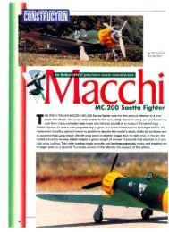
<strong>The</strong> <strong>Fieseler</strong><br />
<strong>Storch</strong><br />
AN ELECTRIC-POWERED VERSION OF THE<br />
LUFTWAFFE’S FAMOUS WW II “STOL” WORKHORSE<br />
MoreOnline!<br />
modelairplanenews.com<br />
For some unknown reason, the<br />
<strong>Fieseler</strong> <strong>Storch</strong> is my favorite<br />
aircraft. Perhaps this goes back<br />
to when I built a 1 ⁄6-scale model<br />
some years ago and became a<br />
student of the prototype. <strong>The</strong> plane has<br />
somewhat of a “cult” following and,<br />
although many argue about its<br />
aesthetics, the <strong>Storch</strong> was quite an<br />
advanced design in the mid-1930s. It was<br />
“the helicopter before they had the<br />
helicopter” and many still fly today,<br />
including replicas. <strong>The</strong> Luftwaffe<br />
employed the aircraft in all theaters of<br />
WW II and it was quite effective in its role<br />
of spotter, transport, rescue and liaison<br />
aircraft. As a model, it is surprisingly<br />
involved to build in any scale. It is these<br />
complexities, however, that make the<br />
aircraft unique.<br />
My design goals were to keep power<br />
and radio equipment out of the massive<br />
cockpit, employ a functional landing<br />
gear, have easy battery and equipment<br />
access and to add lightness. I also<br />
searched far and wide for a cheap, but<br />
gutsy motor.<br />
Backyard Flyer has graciously<br />
included my excruciatingly detailed<br />
construction notes and photos on their<br />
website, modelairplanenews.com and I<br />
recommend that you visit there for help<br />
with the trickier parts. For now, I’ll focus<br />
on some of the model’s idiosyncrasies<br />
along with finishing and setup. I<br />
recommend that the <strong>Storch</strong> be tackled<br />
by more experienced builders, but a<br />
determined newbie should not have too<br />
much trouble if he or she stays focused.<br />
A laser-cut short kit, a vacu-formed<br />
windscreen and upper canopy along<br />
with a fiberglass cowl are all available<br />
from me.<br />
CONSTRUCTION<br />
<strong>The</strong> wing has a standard D-box design<br />
and is conventionally built on a flat<br />
board. Each wing includes flap and<br />
aileron micro servos and four mounting<br />
48 MORE FROM THIS ISSUE AT MODELAIRPLANENEWS.COM<br />
SPECIFICATIONS<br />
MODEL: <strong>Fieseler</strong> <strong>Storch</strong><br />
SCALE: 1 ⁄12<br />
TYPE: electric scale monoplane<br />
WINGSPAN: 46 in.<br />
WING AREA: 276 sq. in.<br />
WEIGHT: 27 oz.<br />
WING LOADING: 14.1 oz./sq. ft.<br />
LENGTH: 31.5 in.<br />
RADIO REQ’D: 5-channels (elevator,<br />
rudder, aileron, throttle, flaps) optional<br />
lights<br />
POWER REQ’D: 18-20A brushless<br />
motor<br />
GEAR USED<br />
RADIO: Spektrum DX7 2.4GHz,<br />
AR6100e receiver, (spektrumrc.com)<br />
Hitec HS-55 servos (hitecrcd.com)<br />
POWER SYSTEM: BP Hobbies A2217-<br />
9 brushless motor (bphobbies.com),<br />
Castle Creations 18A ESC (castlecre<br />
ations.com)<br />
BATTERY: FMA 950mAh 3S 11.1V LiPo<br />
PROP: APC 9x6 or 10x5<br />
(apcprop.com)<br />
points for the functional struts. Build the<br />
ailerons and flaps with the wing. <strong>The</strong> tail<br />
surfaces are also very easy to build. <strong>The</strong><br />
fixed surfaces are sheeted “stick”<br />
frameworks and the movable sections<br />
are built up over balsa core outlines.<br />
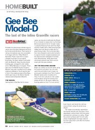
<strong>The</strong> <strong>Storch</strong>’s fuselage is comprised of<br />
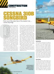
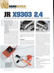
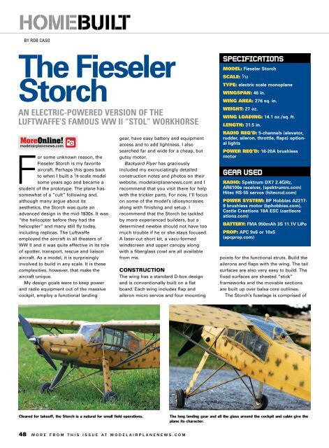
Cleared for takeoff, the <strong>Storch</strong> is a natural for small field operations. <strong>The</strong> long landing gear and all the glass around the cockpit and cabin give the<br />
plane its character.
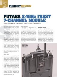
ITALIAN STORCH?<br />
Why did you pick an Italian paint scheme for your <strong>Storch</strong>?<br />
Rob Caso: I already had built four or five <strong>Storch</strong>s, both RC and<br />
plastic models. Having painted them all in Luftwaffe camouflage, I<br />
was looking for something a bit different. My good friend, Vince<br />
Nigrelli, has been nagging me to design “something Italian” and I<br />
got to thinking that maybe I could paint my <strong>Storch</strong> in a Regia<br />
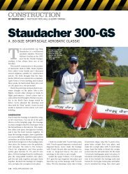
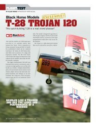
<strong>The</strong> author shows<br />
off his pride and joy.<br />
Aeronautica scheme. Like most of what the Italians do, their WW<br />
II schemes were almost artistic and I really wanted to do a lighter<br />
scheme since they show up better at the field. I plinked around on<br />
the Internet and discovered a <strong>Storch</strong> in an Italian museum that has<br />
a scheme very close to the one I did here. With the almost yellow<br />
base coat and the white wingtips, the model really shows up well<br />
in the air and is quite photogenic.<br />
MAY 2010 49
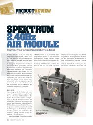
HOMEBUILT<br />
Since the model is not built with flat side-to-side<br />
construction methods, a fuselage jig is need to<br />
assemble and keep the cabin section in proper<br />
alignment.<br />
forward and aft assemblies attached to a<br />
ventral spine. A combination battery box,<br />
servo and motor mount is attached to the<br />
nose. This assembly is equipment<br />
specific—there is not much room and if<br />
you deviate too much, you may have fit<br />
problems with the slender cowl. If I had<br />
to do it again, I’d seriously consider<br />
putting the receiver behind bulkhead no.<br />
8 and then make the starboard access<br />
hatch functional. This would reduce the<br />
number of visible wires in the cockpit. A<br />
common misperception with the <strong>Storch</strong><br />
is that the fuselage wing root area has to<br />
be built excessively strong to handle<br />
flight and landing loads. <strong>The</strong>re is very<br />
little stress on the model at the root<br />
because due to the cantilever location of<br />
wing struts, there is actually a net<br />
downward force on the root when the<br />
model is in flight. Thus, the struts (and<br />
f<br />
To order the full-size plan, visit RCStore.com.<br />
Here, the nose and tail sections have been<br />
attached to the cabin structure.<br />
mounts) do all the work and these must<br />
be the strong components in the chain.<br />
<strong>The</strong> toughest structure to make in<br />
scale modeling is a leading edge slat\ or<br />
spoiler, and the <strong>Storch</strong> has two of them. I<br />
devised a “buck” system, which is<br />
nothing more than a copy of the wing’s<br />
leading edge over which two sheets of<br />
soft 1 ⁄32-inch balsa are laminated together<br />
to form a curve. Yes, it’s more work, but<br />
it will yield a much more accurate part.<br />
Apply packaging tape to prevent the slat<br />
from adhering to the form. Wet the slat<br />
laminates with ammonia-based window<br />
cleaner until soggy, apply epoxy to each<br />
and stack the pieces. Evenly position this<br />
over the buck, bend it around the leading<br />
edge and wrap the entire lamination with<br />
tape. Allow the assembly to dry<br />
overnight. Apply two soft strips of balsa<br />
to the leading edge and sand to an airfoil<br />
50 MORE FROM THIS ISSUE AT MODELAIRPLANENEWS.COM<br />
<strong>The</strong> strut mounts were later changed to a single<br />
hole for the mounting 4-40 screw; a blind nut is<br />
used to secure the screw.<br />
cross section. <strong>The</strong> buck is quite sturdy<br />
and may be used to support the slat<br />
during sanding and finishing. I applied<br />
multiple coats of thinned nitrate dope to<br />
the slats; between this and the epoxy, the<br />
balsa became very resilient.<br />
LANDING GEAR<br />
<strong>The</strong> stalky landing gear is a trademark of<br />
the <strong>Storch</strong> and they really soak up<br />
forward motion on touch down, thus<br />
facilitating short landings. <strong>The</strong> sprung<br />
“oleo” is made from sections of tubes,<br />
springs and music wire, while the Vstruts<br />
are carbon-fiber tubing. <strong>The</strong> pivot<br />
points that hold everything together are<br />
flattened brass tube “lugs,” drilled to<br />
accept 2-56 screws. <strong>The</strong> only real tricky<br />
part is getting the upper struts to line up<br />
side to side and making identical parts<br />
for each side. Make a “kit” of cut tube,
take a deep breath and dive in while<br />
being stingy with the solder. It’s actually<br />
a very simple assembly.<br />
COVERING, DETAILS AND<br />
FINISHING<br />
<strong>The</strong>re are two canopies: an upper and a<br />
windscreen. Installing the upper one is<br />
easy. <strong>The</strong> windscreen requires a number<br />
of incremental cuts to coax it in between<br />
bulkheads no. 3 and 5 and around the<br />
landing gear struts.<br />
<strong>The</strong> upper and lower cowls are affixed<br />
to the model with locating pins and<br />
magnets. <strong>The</strong> upper cowl is fitted using<br />
lite-ply mounts shown in the plans. Glue<br />
in the mounts to the upper with the cowl<br />
positioned on the model.<br />
To fit the lower cowl, glue in crosswise<br />
pieces to each cowl at the nose. <strong>The</strong>re is<br />
also an aft mounting point for lower cowl<br />
on the fuselage. Glue up the aft mount to<br />
the fuselage with its mating piece<br />
attached and flush with the bulkhead.<br />
Install the cowl and glue the aft mating<br />
piece to the cowl. Once lower cowl<br />
mounts are in place, its forward mounts<br />
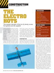
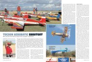
Here the wing structure is complete with the flap<br />
and aileron surfaces ready to be closed up. All<br />
the hard points and hinge support blocks should<br />
be in place before applying the sheeting.<br />
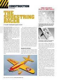
Here the basic airframe takes shape with the<br />
fiberglass engine cowl slipped into place.<br />
With its leading edge<br />
slats, the <strong>Storch</strong> has<br />
excellent slow speed<br />
flight performance.<br />
are cut to clear the motor.<br />
I used Sig Mfg. Koverall to cover the<br />
open framework, and I primed the<br />
covering with Minwax Polycrylic. Paint the<br />
model before attaching the clear glazing. I<br />
applied 0.75 ounce fiberglass cloth to the<br />
skinned areas with Polycrylic and then<br />
used a lot of auto body filler and primer<br />
on the cowl, slats, ailerons and flaps prior<br />
to painting. Go for a good surface prep<br />
and don’t worry about the weight.<br />
<strong>The</strong> <strong>Storch</strong> displayed a number of<br />
interesting paint schemes and I used<br />
plastic model paint and single- and dualaction<br />
airbrushes to apply the Italian air<br />
force scheme and markings. I generally<br />
choose lightly colored schemes for small<br />
models as darker schemes tend to make<br />
small models look even smaller. Aside<br />
from the standard RLM black<br />
green/green, there were also a number of<br />
tropical and winter schemes. <strong>The</strong> <strong>Storch</strong><br />
<strong>The</strong> leading edge slat “buck” is used to form<br />
slats. Note that 3 ⁄16x 1 ⁄8-inch strips are applied to<br />
the slat’s leading edge after the sheeting is laminated<br />
together.<br />
also wore various national insignia other<br />
than German including Swedish, French,<br />
Italian, Spanish and even British and U.S.<br />
Eisenhower’s personal transportation in<br />
Europe after the war included a Morainebuilt<br />
<strong>Storch</strong> (“Criquet”).<br />
FINAL DETAILS<br />
<strong>The</strong> forward bulkheads incorporate holes<br />
to run servo wiring beneath the cockpit<br />
floor in the event a full cockpit is to be<br />
installed. In this case, you must pre-wire<br />
the model as it’s being built and make<br />
your own connectors. With respect to the<br />
wings, either run the servo wires during<br />
construction or make provisions to fish<br />
them through before the wings are<br />
skinned and covered. I ran long servo<br />
leads between each aileron and flap<br />
servo. Where these crossed the cabin, I<br />
separated sections of insulation without<br />
breaking the wires and soldered in the<br />
<strong>The</strong> moveable control surfaces are built with a<br />
simple sandwich of 1 ⁄16-inch balsa core outline<br />
and supporting frameworks on either side.<br />
MAY 2010 51
HOMEBUILT<br />
MÉAL<br />
XAVIER<br />
BEFORE THERE WERE HELICOPTERS,<br />
BY<br />
THERE WAS THE STORCH! PHOTO<br />
Even though I had seen many pictures of the <strong>Storch</strong>, nothing<br />
could possibly convey its size and general ungainliness. It<br />
stands so high off the ground that an average man can<br />
barely see in the side windows. In fact, we doubt that<br />
there’s a man alive who could step from the ground to the door sill,<br />
once the huge, multi-faceted door is pulled out and up and<br />
fastened to the bottom of the wing. This isn’t an airplane, it’s a<br />
three-dimensional, whimsical caricature of an airplane.<br />
Traditionally, the whole idea of aviation has centered on<br />
efficiency—getting the most speed from the least horsepower.<br />
This airplane, clearly, works on the opposite premise. If there is an<br />
airplane with more drag-producing protuberances, I’ve never seen<br />
it. Aerodynamically, the <strong>Storch</strong> makes a tumbleweed look slick.<br />
Maneuvering in the <strong>Storch</strong> is a real physical workout. <strong>The</strong> controls<br />
leads that run to the receiver residing<br />
behind the instrument panel. Use “Liquid<br />
Electrical Tape” to insulate the solder<br />
joints. When I was done, I basically had<br />
two giant “Y” connectors. With the<br />
receiver so located, it’s an easy run for<br />
the ESC, rudder and elevator leads.<br />
Unless you use a dedicated channel for<br />
each flap servo, these must be oriented<br />
the same on each wing while the aileron<br />
servos are opposite.<br />
IN THE AIR<br />
My power system analysis using the<br />
MotoCalc program indicated that there<br />
were two possible props for the <strong>Storch</strong>; a<br />
9x6 and 10x5. Each had good wattage<br />
figures, but the 10x5 had a significant<br />
advantage in static thrust—28 ounces vs.<br />
22 ounces produced by the 9x6 prop, at<br />
the expense of some flying time and top<br />
speed. Install the 9x6 first to get a feel for<br />
the model and then go for the high-thrust<br />
setup.<br />
Balance the model leaning towards<br />
nose heavy. <strong>The</strong> wing’s center of lift is<br />
more forward due to the slats, at about<br />
25% of MAC. Also, don’t forget to<br />
balance the model laterally, wingtip to<br />
wingtip. Aileron throws should be about<br />
52 MORE FROM THIS ISSUE AT MODELAIRPLANENEWS.COM<br />
feel the way the airplane looks—gawky and loose. <strong>The</strong> stick<br />
forces are anything but light and to keep it completely<br />
coordinated, your feet have to thrash in and out as if you were<br />
working an old sewing machine.<br />
What is it about a <strong>Fieseler</strong> <strong>Storch</strong> that appeals to something in<br />
all of us? It certainly isn’ the <strong>Storch</strong>’s blazing cruise of 70 knots or<br />
its 1600rpm full-throttle sound. Nor is it loved for its streamlined<br />
gracefulness. Maybe it’s the idea of having an airplane that<br />
converts your backyard into an airport, or maybe it’s the part the<br />
<strong>Storch</strong> has played in history. For me, the <strong>Storch</strong> has appeal<br />
because it doesn’t try to be pretty. It’s a good honest ugly and<br />
doesn’t seem to care.<br />
— Budd Davisson<br />
VISIT BUDD ON THE WEB AT AIRBUM.COM<br />
3 ⁄8 inch for each direction, with “all you<br />
can get” on the rudder and elevator. Use<br />
about 25% exponential on the ailerons<br />
and elevator as a start and add or<br />
decrease expo and throw depending on<br />
your flying style.<br />
Slow flying will require a lot of control<br />
surface throw. Although it has trainer-like<br />
stats, the model will go only were you<br />
put it and will not self correct. Short<br />
landings take a little practice, the key to<br />
which is keeping the model pitched up<br />
and under power as you come in. Once<br />
the wheels touch, immediately cut the<br />
power. A