
Create successful ePaper yourself
Turn your PDF publications into a flip-book with our unique Google optimized e-Paper software.
take a deep breath and dive in while<br />
being stingy with the solder. It’s actually<br />
a very simple assembly.<br />
COVERING, DETAILS AND<br />
FINISHING<br />
<strong>The</strong>re are two canopies: an upper and a<br />
windscreen. Installing the upper one is<br />
easy. <strong>The</strong> windscreen requires a number<br />
of incremental cuts to coax it in between<br />
bulkheads no. 3 and 5 and around the<br />
landing gear struts.<br />
<strong>The</strong> upper and lower cowls are affixed<br />
to the model with locating pins and<br />
magnets. <strong>The</strong> upper cowl is fitted using<br />
lite-ply mounts shown in the plans. Glue<br />
in the mounts to the upper with the cowl<br />
positioned on the model.<br />
To fit the lower cowl, glue in crosswise<br />
pieces to each cowl at the nose. <strong>The</strong>re is<br />
also an aft mounting point for lower cowl<br />
on the fuselage. Glue up the aft mount to<br />
the fuselage with its mating piece<br />
attached and flush with the bulkhead.<br />
Install the cowl and glue the aft mating<br />
piece to the cowl. Once lower cowl<br />
mounts are in place, its forward mounts<br />
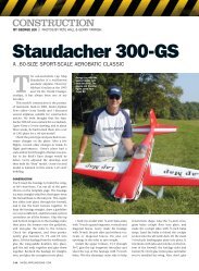
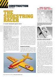
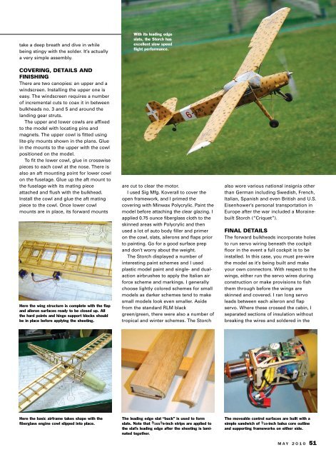
Here the wing structure is complete with the flap<br />
and aileron surfaces ready to be closed up. All<br />
the hard points and hinge support blocks should<br />
be in place before applying the sheeting.<br />
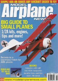
Here the basic airframe takes shape with the<br />
fiberglass engine cowl slipped into place.<br />
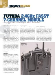
With its leading edge<br />
slats, the <strong>Storch</strong> has<br />
excellent slow speed<br />
flight performance.<br />
are cut to clear the motor.<br />
I used Sig Mfg. Koverall to cover the<br />
open framework, and I primed the<br />
covering with Minwax Polycrylic. Paint the<br />
model before attaching the clear glazing. I<br />
applied 0.75 ounce fiberglass cloth to the<br />
skinned areas with Polycrylic and then<br />
used a lot of auto body filler and primer<br />
on the cowl, slats, ailerons and flaps prior<br />
to painting. Go for a good surface prep<br />
and don’t worry about the weight.<br />
<strong>The</strong> <strong>Storch</strong> displayed a number of<br />
interesting paint schemes and I used<br />
plastic model paint and single- and dualaction<br />
airbrushes to apply the Italian air<br />
force scheme and markings. I generally<br />
choose lightly colored schemes for small<br />
models as darker schemes tend to make<br />
small models look even smaller. Aside<br />
from the standard RLM black<br />
green/green, there were also a number of<br />
tropical and winter schemes. <strong>The</strong> <strong>Storch</strong><br />
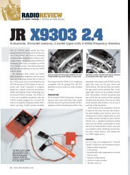
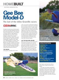
<strong>The</strong> leading edge slat “buck” is used to form<br />
slats. Note that 3 ⁄16x 1 ⁄8-inch strips are applied to<br />
the slat’s leading edge after the sheeting is laminated<br />
together.<br />
also wore various national insignia other<br />
than German including Swedish, French,<br />
Italian, Spanish and even British and U.S.<br />
Eisenhower’s personal transportation in<br />
Europe after the war included a Morainebuilt<br />
<strong>Storch</strong> (“Criquet”).<br />
FINAL DETAILS<br />
<strong>The</strong> forward bulkheads incorporate holes<br />
to run servo wiring beneath the cockpit<br />
floor in the event a full cockpit is to be<br />
installed. In this case, you must pre-wire<br />
the model as it’s being built and make<br />
your own connectors. With respect to the<br />
wings, either run the servo wires during<br />
construction or make provisions to fish<br />
them through before the wings are<br />
skinned and covered. I ran long servo<br />
leads between each aileron and flap<br />
servo. Where these crossed the cabin, I<br />
separated sections of insulation without<br />
breaking the wires and soldered in the<br />
<strong>The</strong> moveable control surfaces are built with a<br />
simple sandwich of 1 ⁄16-inch balsa core outline<br />
and supporting frameworks on either side.<br />
MAY 2010 51