SERVICE SPECIFICATIONS
SERVICE SPECIFICATIONS
SERVICE SPECIFICATIONS

Create successful ePaper yourself
Turn your PDF publications into a flip-book with our unique Google optimized e-Paper software.
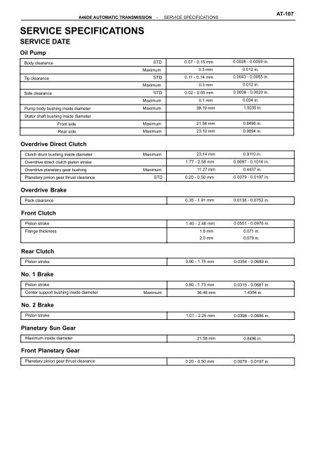
<strong>SERVICE</strong> <strong>SPECIFICATIONS</strong><br />
<strong>SERVICE</strong> DATE<br />
Oil Pump<br />
Body clearance STD 0.07 - 0.15 mm 0.0028 - 0.0059 in.<br />
Maximum 0.3 mm 0.012 in.<br />
Tip clearance STD 0.11 - 0.14 mm 0.0043 - 0.0055 in.<br />
Maximum 0.3 mm 0.012 in.<br />
Side clearance STD 0.02 - 0.05 mm 0.0008 - 0.0020 in.<br />
Maximum 0.1 mm 0.004 in.<br />
Pump body bushing inside diameter<br />
Stator shaft bushing inside diameter<br />
Maximum 38.19 mm 1.5035 in.<br />
Front side Maximum 21.58 mm 0.8496 in.<br />
Rear side Maximum<br />
23.10 mm 0.9094 in.<br />
Overdrive Direct Clutch<br />
Clutch drum bushing inside diameter Maximum 23.14 mm 0.9110 in.<br />
Overdrive direct clutch piston stroke 1.77 - 2.58 mm 0.0697 - 0.1016 in.<br />
Overdrive planetary gear bushing Maximum 11.27 mm 0.4437 in.<br />
Planetary pinion gear thrust clearance STD<br />
0.20 - 0.50 mm 0.0079 - 0.0197 in.<br />
Overdrive Brake<br />
Pack clearance 0.35 - 1.91 mm 0.0138 - 0.0752 in.<br />
Front Clutch<br />
Piston stroke 1.40 - 2.48 mm 0.0551 - 0.0976 in.<br />
Flange thickness 1.8 mm<br />
0.071 in.<br />
2.0 mm<br />
0.079 in.<br />
Rear Clutch<br />
Piston stroke 0.90 - 1.75 mm 0.0354 - 0.0689 in.<br />
No. 1 Brake<br />
Piston stroke 0.80 - 1.73 mm 0.0315 - 0.0681 in.<br />
Center support bushing inside diameter Maximum<br />
36.46 mm 1.4354 in.<br />
No. 2 Brake<br />
Piston stroke 1.01 - 2.25 mm 0.0398 - 0.0886 in.<br />
Planetary Sun Gear<br />
Maximum inside diameter 21.58 mm 0.8496 in.<br />
Front Planetary Gear<br />
A46DE AUTOMATIC TRANSMISSION - <strong>SERVICE</strong> <strong>SPECIFICATIONS</strong><br />
Planetary pinion gear thrust clearance 0.20 - 0.50 mm 0.0079 - 0.0197 in.<br />
AT-107
AT-108<br />
Rear Planetary Gear<br />
Planetary pinion gear thrust clearance 0.20 - 0.50 mm 0.0079 - 0.0197 in.<br />
No. 3 Brake<br />
Pack clearance 0.61 - 2.64 mm 0.0240 - 0.1039 in.<br />
Valve Body Spring<br />
Spring<br />
Free length and Coil outer<br />
diameter<br />
mm (in.)<br />
Total No. of coils and Color<br />
(Front upper valve body)<br />
Secondary regulator valve 71.3 (2.807) 17.4 (0.685) 17.0 Green<br />
Down shift plug 39.6 (1.590) 10.9 (0.429)<br />
11.4 Green<br />
Throttle valve 21.9 (0.862) 8.6 (0.339) 10.0<br />
None<br />
Cut-back valve<br />
(Rear upper valve body)<br />
23.0 (0.906) 6.9 (0.272)<br />
12.5<br />
Green<br />
2 - 3 shift valve 29.2 (1.150) 8.9 (0.350)<br />
12.0<br />
Blue<br />
3 - 4 shift valve 29.2 (1.150) 8.9 (0.350)<br />
12.0<br />
Blue<br />
1 - 2 shift valve 29.2 (1.150) 8.9 (0.350)<br />
12.0<br />
Blue<br />
Reverse clutch sequence valve<br />
(Lower valve body)<br />
37.6 (1.480) 9.2 (0.362)<br />
16.5<br />
None<br />
Low coast modulator valve 42.4 (1.669) 9.2 (0.362)<br />
17.0<br />
None<br />
Check ball (Cooler return) 13.7 (0.539) 10.5 (0.413) 10.0<br />
None<br />
Cooler by-pass valve 28.0 (1.102) 13.6 (0.535)<br />
8.0 Blue<br />
Check ball (Damping check ball) 20.0 (0.787) 5.0 (0.196) 18.0<br />
None<br />
Intermediate modulator valve 35.4 (1.394) 8.8 (0.346) 16.4<br />
Red<br />
Lock-up relay valve 32.6 (1.283) 11.4 (0.449)<br />
10.3<br />
Green<br />
Pressure relief valve 32.1 (1.264) 13.1 (0.516)<br />
11.0<br />
None<br />
Primary regulator valve 50.3 (1.980) 17.0 (0.669) 12.5<br />
Blue<br />
Valve Body Key<br />
(Front upper valve body)<br />
Retainer<br />
Height<br />
mm (in.)<br />
Width<br />
mm (in.)<br />
Thickness<br />
mm (in.)<br />
Cut-back valve 19.0 (0.748) 5.0 (0.197) 3.2 (0.126)<br />
(Rear upper valve body)<br />
2 - 3 shift valve 10.0 (0.394) 5.0 (0.197) 3.2 (0.126)<br />
3 - 4 shift valve 10.0 (0.394) 5.0 (0.197) 3.2 (0.126)<br />
(Lower valve body)<br />
Primary regulator valve 17.5 (0.689) 14.0 (0.551) 3.2 (0.126)<br />
Transmission Case<br />
Transmission case bushing Maximum 38.19 mm 1.5035 in.<br />
Extension Housing<br />
A46DE AUTOMATIC TRANSMISSION - <strong>SERVICE</strong> <strong>SPECIFICATIONS</strong><br />
Extension housing bushing Maximum 38.09 mm 1.4996 in.
Output Shaft<br />
End play 0.3 - 0.9 mm 0.012 - 0.035 in.<br />
Output shaft bushing Maximum<br />
18.08 mm 0.7118 in.<br />
Accumulator Spring<br />
C 1<br />
C 2<br />
B 2<br />
Spring<br />
TORQUE SPECIFICATION<br />
A46DE AUTOMATIC TRANSMISSION - <strong>SERVICE</strong> <strong>SPECIFICATIONS</strong><br />
Free length / Outer diameter<br />
mm (in.)<br />
Color<br />
64.4 (2.535) / 17.5 (0.689) None<br />
57.4 (2.260) / 15.9 (0.626) None<br />
32.0 (1.260) / 15.4 (0.606) Yellow<br />
Part tightened N-m kgf-cm ft-lbf<br />
Stator shaft × Oil pump body 7.4 75 65 in.-lbf<br />
Lower valve body × Front upper valve body 5.4 55 48 in.-lbf<br />
Lower valve body × Rear upper valve body 5.4 55 48 in.-lbf<br />
Center support × Transmission case 25 260 19<br />
Transmission housing × Transmission case<br />
10 mm bolt<br />
34<br />
345<br />
25<br />
12 mm bolt<br />
57<br />
580<br />
42<br />
Oil pump × Transmission case 21 215 16<br />
Parking lock pawl bracket 7.4 75 65 in.-lbf<br />
Valve body × Transmission case 10 100 7<br />
Oil strainer × Valve body 5.4 55 48 in.-lbf<br />
Oil pan × Transmission case 4.4 45 39 in.-lbf<br />
Governor body lock plate 3.9 40 35 in.-lbf<br />
Extension housing × Transmission case 34 345 25<br />
Union 34 345 25<br />
Park/Neutral position switch 3.9 40 35 in.-lbf<br />
Park/Neutral position switch adjusting bolt 5.4 55 48 in.-lbf<br />
AT-109
AT-10<br />
PREPARATION<br />
SST (SPECIAL <strong>SERVICE</strong> TOOLS)<br />
RECOMMENDED TOOLS<br />
A46DE AUTOMATIC TRANSMISSION - PREPARATION<br />
09350 - 20015<br />
(09350 - 06120)<br />
(09361 - 30011)<br />
(09362 - 30011)<br />
(09363 - 20010)<br />
(09369 - 20040)<br />
(09370 - 12010)<br />
09350 - 30020<br />
(09350 - 07080)<br />
(09350 - 07090)<br />
09031 - 00030<br />
TOYOTA Automatic Transmission<br />
Tool Set<br />
No. 2 Measure Terminal<br />
Manual Valve Lever Shaft Oil<br />
Seal Replacer<br />
Guide Bolt<br />
Oil Pump Body Setting Band<br />
Piston Spring Compressor Set<br />
Clutch Drum Thrust Play Gauge<br />
TOYOTA Automatic Transmission<br />
Tool Set<br />
Brake Reaction Sleeve Puller<br />
Brake No. 1 Piston Puller<br />
09610 - 20012 Pitman Arm Puller<br />
Remove the oil pump.<br />
Pin Punch
EQUIPMENT<br />
Feeler gauge<br />
Vernier calipers<br />
Dial indicator or dial indicator with magnetic base<br />
Dial indicator<br />
Straight edge<br />
Torque wrench<br />
Cylinder gauge<br />
LUBRICANT<br />
Dry fill<br />
Drain and refill<br />
A46DE AUTOMATIC TRANSMISSION - PREPARATION<br />
Item Capacity Classification<br />
5.7 liters (6.0 US qts, 5.0 Imp. qts)<br />
2.4 liters (2.5 US qts, 2.1 Imp. qts)<br />
ATF DEXRON II<br />
SSM (SPECIAL <strong>SERVICE</strong> MATERIALS)<br />
08833 - 00080 Adhesive 1344,<br />
Oil pump set bolt<br />
THREE BOND 1344,<br />
LOCTITE 242 or equivalent<br />
Extension housing set bolt<br />
AT-1 1
AT-106<br />
<strong>SERVICE</strong> <strong>SPECIFICATIONS</strong><br />
<strong>SERVICE</strong> DATE<br />
Oil Pump<br />
Body clearance STD<br />
0.07 - 0.15 mm 0.0028 - 0.0059 in.<br />
Maximum 0.3 mm<br />
0.012 in.<br />
Tip clearance STD 0.11 - 0.14 mm 0.0043 - 0.0055 in.<br />
Maximum 0.3 mm<br />
0.012 in.<br />
Side clearance STD<br />
0.02 - 0.05 mm 0.0008 - 0.0020 in.<br />
Maximum 0.1 mm<br />
0.004 in.<br />
Pump body bushing inside diameter<br />
Stator shaft bushing inside diameter<br />
Maximum<br />
38.19 mm 1.5035 in.<br />
Front side Maximum 21.58 mm<br />
0.8496 in.<br />
Rear side Maximum<br />
23.10 mm<br />
0.9094 in.<br />
Overdrive Direct Clutch<br />
Clutch drum bushing inside diameter Maximum 23.14 mm<br />
0.9110 in.<br />
Overdrive direct clutch piston stroke 1.77 - 2.58 mm 0.0697 - 0.1016 in.<br />
Overdrive planetary gear bushing Maximum<br />
11.27 mm 0.4437 in.<br />
Planetary pinion gear thrust clearance STD 0.20 - 0.50 mm 0.0079 - 0.0197 in.<br />
Overdrive Brake<br />
Pack clearance 0.35 - 1.91 mm 0.0138 - 0.0752 in.<br />
Front Clutch<br />
Piston stroke 1.40 - 2.48 mm 0.0551 - 0.0976 in.<br />
Flange thickness 1.8 mm<br />
0.071 in.<br />
2.0 mm<br />
0.079 in.<br />
Rear Clutch<br />
Piston stroke 0.90 - 1.75 mm 0.0354 - 0.0689 in.<br />
No. 1 Brake<br />
Piston stroke 0.80 - 1.73 mm 0.0315 - 0.0681 in.<br />
Center support bushing inside diameter Maximum 36.46 mm 1.4354 in.<br />
No. 2 Brake<br />
Piston stroke 1.01 - 2.25 mm 0.0398 - 0.0886 in.<br />
Planetary Sun Gear<br />
Maximum inside diameter 21.58 mm 0.8496 in.<br />
Front Planetary Gear<br />
A46DF AUTOMATIC TRANSMISSION - <strong>SERVICE</strong> <strong>SPECIFICATIONS</strong><br />
Planetary pinion gear thrust clearance 0.20 - 0.50 mm 0.0079 - 0.0197 in.
Rear Planetary Gear<br />
Planetary pinion gear thrust clearance 0.20 - 0.50 mm 0.0079 - 0.0197 in.<br />
No. 3 Brake<br />
Pack clearance 0.61 - 2.64 mm 0.0240 - 0.1039 in.<br />
Valve Body Spring<br />
Spring<br />
(Front upper valve body)<br />
Free length and Coil outer<br />
diameter mm (in.)<br />
Total No. of coils and Color<br />
Secondary regulator valve 71.3 (2.807) 17.4 (0.685)<br />
17.0 Green<br />
Down shift plug 39.6 (1.560) 10.9 (0.429) 11.4 Green<br />
Throttle valve 21.9 (0.862) 8.6 (0.339) 10.0 None<br />
Cut-back valve 23.0 (0.906) 6.9 (0.272) 12.5 Green<br />
(Rear upper valve body)<br />
2 - 3 shift valve 29.2 (1.150) 8.9 (0.350) 12.0 Blue<br />
3 - 4 shift valve 29.2 (1.150) 8.9 (0.350) 12.0 Blue<br />
1 - 2 shift valve 29.2 (1.150) 8.9 (0.350) 12.0 Blue<br />
Reverse clutch sequence valve<br />
(Lower valve body)<br />
37.6 (1.480) 9.2 (0.362) 16.5 None<br />
Low coast modulator valve 42.4 (1.669) 9.2 (0.362) 17.0 None<br />
Check ball (Cooler return) 13.7 (0.539) 10.5 (0.413) 10.0 None<br />
Cooler by-pass valve 28.0 (1.102) 13.6 (0.535)<br />
8.0 Blue<br />
Check ball (Damping check ball) 20.0 (0.787) 5.0 (0.196)<br />
18.0 None<br />
Intermediate modulator valve 35.4 (1.394) 8.8 (0.346) 16.4 Red<br />
Lock-up relay valve 32.6 (1.283) 11.4 (0.449) 10.3 Green<br />
Pressure relief valve 32.1 (1.264) 13.1 (0.516)<br />
11.0 None<br />
Primary regulator valve 50.3 (1.980) 17.0 (0.669) 12.5<br />
Blue<br />
Valve Body Key<br />
Retainer<br />
Height<br />
mm (in.)<br />
Width<br />
mm (in.)<br />
Thickness<br />
mm (in.)<br />
(Front upper valve body)<br />
Cut-back valve<br />
(Rear upper valve body)<br />
19.0 (0.748) 5.0 (0.197) 3.2 (0.126)<br />
2 - 3 shift valve 10.0 (0.394) 5.0 (0.197) 3.2 (0.126)<br />
3 - 4 shift valve<br />
(Lower valve body)<br />
10.0 (0.394) 5.0 (0.197) 3.2 (0.126)<br />
Primary regulator valve 17.5 (0.689) 14.0 (0.551) 3.2 (0.126)<br />
Transmission Case<br />
A46DF AUTOMATIC TRANSMISSION - <strong>SERVICE</strong> <strong>SPECIFICATIONS</strong><br />
Transmission case bushing Maximum 38.19 mm<br />
1.5035 in.<br />
AT-107
AT-108<br />
Output Shaft<br />
End play 0.3 - 0.9 mm 0.012 - 0.035 in.<br />
Output shaft bushing Maximum<br />
18.08 mm 0.7118 in.<br />
Accumulator Spring<br />
Spring<br />
Free length / Outer diameter mm<br />
(in.) Color<br />
C 1 64.4 (2.535) / 17.5 (0.689) None<br />
C 2 57.4 (2.260) / 15.9 (0.626) None<br />
B 2 32.0 (1.260) / 15.4 (0.606) Yellow<br />
TORQUE SPECIFICATION<br />
A46DF AUTOMATIC TRANSMISSION - <strong>SERVICE</strong> <strong>SPECIFICATIONS</strong><br />
Part tightened N-m kgf-cm ft-lbf<br />
Stator shaft × Oil pump body 7.4 75 65 in.-lbf<br />
Lower valve body × Front upper valve body 5.4 55 48 in.-lbf<br />
Lower valve body × Rear upper valve body 5.4 55 48 in.-lbf<br />
Center support × Transmission case 25 260 19<br />
Transmission housing × Transmission case 10 mm bolt<br />
34<br />
345<br />
25<br />
12 mm bolt<br />
57<br />
580<br />
42<br />
Oil pump × Transmission case 21 215 16<br />
Parking lock pawl bracket 7.4 75 65 in.-lbf<br />
Valve body × Transmission case 10 100 7<br />
Oil strainer × Valve body 5.4 55 48 in.-lbf<br />
Oil pan × Transmission case 4.4 45 39 in.-lbf<br />
Governor body lock plate 3.9 40 35 in.-lbf<br />
Transfer adapter × Transmission case 34 345 25<br />
Transfer adapter × Transfer 45 455 33<br />
Elbow 34 350 25<br />
A/T oil temperature sensor × Front elbow 34 350 25<br />
Park/Neutral position switch 3.9 40 35 in.-lbf<br />
Park/Neutral position switch adjusting bolt 5.4 55 48 in.-lbf
AT-10<br />
PREPARATION<br />
SST (SPECIAL <strong>SERVICE</strong> TOOLS)<br />
RECOMMENDED TOOLS<br />
A46DF AUTOMATIC TRANSMISSION - PREPARATION<br />
09350 - 20015<br />
(09350 - 06120)<br />
09361 - 30011<br />
(09362 - 30011)<br />
09363 - 20010<br />
(09369 - 20040)<br />
(09370 - 12010)<br />
09350 - 30020<br />
(09350 - 07080)<br />
(09350 - 07090)<br />
09031 - 00030<br />
TOYOTA Automatic Transmission<br />
Tool Set<br />
No. 2 Measure Terminal<br />
Manual Valve Lever Shaft Oil<br />
Seal Replacer<br />
Guide Bolt<br />
Oil Pump Body Setting Band<br />
Piston Spring Compressor Set<br />
Clutch Drum Thrust Play Gauge<br />
TOYOTA Automatic Transmission<br />
Tool Set<br />
Brake Reaction Sleeve Puller<br />
Brake No. 1 Piston Puller<br />
09610 - 20012 Pitman Arm Puller<br />
Remove the oil pump.<br />
Pin Punch
EQUIPMENT<br />
Feeler gauge<br />
Vernier calipers<br />
Dial indicator or dial indicator with magnetic base<br />
Dial indicator<br />
Straight edge<br />
Torque wrench<br />
Cylinder gauge<br />
LUBRICANT<br />
Dry fill<br />
Drain and refill<br />
A46DF AUTOMATIC TRANSMISSION - PREPARATION<br />
Item Capacity Classification<br />
5.7 liters (6.0 US qts, 5.0 Imp. qts)<br />
2.4 liters (2.5 US qts, 2.1 Imp. qts)<br />
ATF DEXRON II<br />
SSM (SPECIAL <strong>SERVICE</strong> MATERIALS)<br />
08833 - 00080 Adhesive 1344,<br />
Oil pump set bolt<br />
THREE BOND 1344,<br />
LOCTITE 242 or equivalent<br />
Transfer adaptor set bolt<br />
AT-1 1
IN-10<br />
INTRODUCTION - ABBREVIATIONS USED IN THIS MANUAL<br />
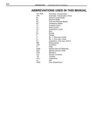
ABBREVIATIONS USED IN THIS<br />
MANUAL<br />
ATF Automatic Transaxle Fluid<br />
B 0<br />
B 1<br />
B 2<br />
B 3<br />
C 0<br />
C 1<br />
C 2<br />
D Disc<br />
F 0<br />
F 1<br />
F 2<br />
Overdrive Brake<br />
No. 1 Brake<br />
No. 2 Brake<br />
No. 3 Brake<br />
Overdrive Clutch<br />
Front Clutch<br />
Rear Clutch<br />
O/D Overdrive<br />
P Plate<br />
O/D One-way Clutch<br />
No. 1 One-way Clutch<br />
No. 2 One-way Clutch<br />
SSM Special Service Materials<br />
SST Special Service Tools
AT-2<br />
DESCRIPTION<br />
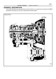
GENERAL<br />
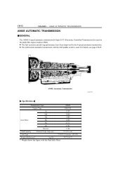
The A46DE is a 4-speed, Electronically Controlled Transmission with lock-up clutch mechanism<br />
developed exclusively for the PREVIA.<br />
The A46DE automatic transmission is mainly composed of a torque converter clutch, an overdrive<br />
(hereafter called O/D) planetary gear unit, a 3-speed planetary gear unit, a hydraulic control system<br />
and an electronic control system.<br />
Sectional View<br />
A46DE AUTOMATIC TRANSMISSION - DESCRIPTION (A46DE)<br />
Q00580
GENERAL <strong>SPECIFICATIONS</strong><br />
Type of Transmission<br />
Type of Engine<br />
Torque Converter Clutch Stall Torque Ratio<br />
Lock-up Mechanism<br />
Gear Ratio<br />
Number of Discs and Plates<br />
A46DE AUTOMATIC TRANSMISSION - DESCRIPTION (A46DE)<br />
1st Gear<br />
2nd Gear<br />
3rd Gear<br />
O/D Gear<br />
Reverse Gear<br />
(Disc and Plate)<br />
O/D Direct Clutch (C0) Forward Clutch (C1) Rear Clutch (C2) No. 2 Brake (B2) No. 3 Brake (B3) O/D Brake (B0) No. 1 Brake (B1) A46DE<br />
2TZ-FE<br />
2.0 : 1<br />
Equipped<br />
2.452<br />
1.452<br />
1.000<br />
0.730<br />
2.212<br />
ATF Type<br />
ATF DEXRON II<br />
Capacity (US qts, Imp. qts) Total<br />
5.7 (6.0, 5.0)<br />
Drain and Refill<br />
2.4 (2.5, 2.1)<br />
1/0<br />
5/5<br />
3/3<br />
3/3<br />
5/4<br />
3/3<br />
2/3<br />
AT-3
AT-2<br />
DESCRIPTION<br />
GENERAL<br />
The A46DF is a 4-speed, Electronically Controlled Transmission with lock-up clutch mechanism<br />
developed exclusively for the PREVIA.<br />
The A46DF automatic transmission is equipped with a full-time four-wheel drive transfer.<br />
The A46DF automatic transmission is mainly composed of a torque converter clutch, an overdrive<br />
(hereafter called O/D) planetary gear unit, a 3-speed planetary gear unit, a hydraulic control system<br />
and an electronic control system.<br />
Sectional View<br />
A46DF AUTOMATIC TRANSMISSION - DESCRIPTION (A46DF)<br />
Q00581
GENERAL <strong>SPECIFICATIONS</strong><br />
Type of Transmission A46DF<br />
Type of Engine 2TZ-FE<br />
Torque Converter Clutch Stall Torque Ratio 2.0: 1<br />
Lock-up Mechanism Equipped<br />
Gear Ratio 1st Gear<br />
2.452<br />
2nd Gear<br />
1.452<br />
3rd Gear<br />
1.000<br />
O/D Gear<br />
0.730<br />
Reverse Gear<br />
2.212<br />
Number of Discs and Plates<br />
A46DF AUTOMATIC TRANSMISSION - DESCRIPTION (A46DF)<br />
(Disc and Plate)<br />
O/D Direct Clutch (C0) Forward Clutch (C1) Rear Clutch (C2) No. 2 Brake (B2) No. 3 Brake (B2) O/D Brake (B0) No. 1 Brake (B1) ATF Type ATF DEXRON II<br />
Capacity (US qts, Imp. qts)<br />
Total<br />
5.7 (6.0, 5.0)<br />
Drain and Refill<br />
2.4 (2.5, 2.1)<br />
1 / 0<br />
5/5<br />
3/3<br />
3/3<br />
5/4<br />
3/3<br />
2/3<br />
AT-3
AT-4<br />
OPERATION<br />
1. OPERATING CONDITIONS<br />
B 0<br />
Ring (i.e.,<br />
Shift Lever<br />
Position)<br />
C0 O/D Planetary Carrier<br />
O/D Planetary Ring Gear<br />
Input Shaft<br />
O/D Planetary<br />
Sun Gear<br />
F0 O/D Input shaft<br />
intermediate Shaft<br />
Gear<br />
C 1<br />
No. 1<br />
Solenoid<br />
Valve<br />
No. 2<br />
Solenoid<br />
Valve<br />
C 0<br />
C 2<br />
C 1<br />
B 1<br />
F 1<br />
B 2<br />
F 2<br />
B3 Front Planetary Ring Gear<br />
Rear Planetary Ring Gear<br />
Sun Gear<br />
Front Planetary<br />
Carrier<br />
C2 B3 B0 B1 B2 I.P. O.P. I.P. O.P.<br />
Output Shaft<br />
Rear Planetary<br />
Carrier<br />
P Parking <br />
R Reverse <br />
N Neutral <br />
D<br />
2<br />
A46DE AUTOMATIC TRANSMISSION - OPERATION (A46DE)<br />
AT3283<br />
F 0 F 1 F 2<br />
1st ON OFF <br />
2nd ON ON <br />
3rd OFF ON <br />
O/D OFF OFF <br />
1st ON OFF <br />
2nd ON ON <br />
L 1st ON OFF <br />
I.P...........Inner Piston<br />
O.P. .........Outer Piston<br />
V02873
2. FUNCTION OF COMPONENTS<br />
COMPONENT FUNCTION<br />
O/D Direct Clutch (C 0) Connects overdrive sun gear and overdrive carrier<br />
O/D Brake (B 0)<br />
O/D One-Way Clutch (F 0)<br />
Front Clutch (C 1)<br />
Prevents overdrive sun gear from turning either clockwise or counterclockwise<br />
When transmission is being driven by engine, connects overdrive sun gear and<br />
overdrive carrier<br />
Connects input shaft and intermediate shaft<br />
Rear Clutch (C 2) Connects input shaft and front & rear planetary sun gear<br />
No. 1 Brake (B 1)<br />
No. 2 Brake (B 2)<br />
Prevents front & rear planetary sun gear from turning either clockwise or<br />
counterclockwise<br />
Prevents outer race of F 1 from turning either clockwise or counterclockwise, thus<br />
preventing front & rear planetary sun gear from turning counterclockwise<br />
No. 3 Brake (B 3) Prevents front planetary carrier from turning either clockwise or counterclockwise<br />
No. 1 One-Way Clutch (F 1)<br />
When B 2 is operating, prevents front & rear planetary sun gear from turning<br />
counterclockwise<br />
No. 2 One-Way Clutch (F 2) Prevents front planetary carrier from turning counterclockwise<br />
O/D Input<br />
Shaft<br />
A46DE AUTOMATIC TRANSMISSION - OPERATION (A46DE)<br />
O/D Sun Gear Input Shaft Sun Gear Rear Planetary Ring Gear<br />
O/D Planetary Ring Gear<br />
O/D Planetary Carrier<br />
Intermediate<br />
Shaft<br />
Front Planetary<br />
Ring Gear<br />
Front Planetary Carrier<br />
Rear Planetary Carrier<br />
Output Shaft<br />
AT3282<br />
AT-5<br />
V02760
AT-6<br />
D or 2 Position 1st Gear<br />
D Position 2nd Gear<br />
D or 2 Position 3rd Gear<br />
D Position O/D<br />
A46DE AUTOMATIC TRANSMISSION - OPERATION (A46DE)<br />
The conditions of operation for each gear position are shown in the following illustrations:<br />
AT7802<br />
AT7803<br />
AT7804<br />
AT7805<br />
V02761
2 or L Position 2nd Gear<br />
L Position 1st Gear<br />
R Position Reverse Gear<br />
A46DE AUTOMATIC TRANSMISSION - OPERATION (A46DE)<br />
AT7806<br />
AT7807<br />
AT7808<br />
AT-7<br />
V02759
AT-8<br />
3. HYDRAULIC CONTROL SYSTEM<br />
The hydraulic control system is composed of the oil pump, the valve body, the governor body, the<br />
accumulators, the clutches and brakes as well as the fluid passage which connect all of these components.<br />
Based in the hydraulic pressure created by the oil pump, the hydraulic control system<br />
governs the hydraulic pressure acting on the torque converter clutch, clutches and brakes in accordance<br />
with the vehicle driving conditions.<br />
There are three solenoid valves on the valve body.<br />
The No. 1 and No. 2 solenoid valves are turned on and off by signals from the ECM to operate the<br />
shift valves and change the gear shift position.<br />
The No. 3 solenoid valve is operated by signals from the ECM to engage or disengage the lockup<br />
clutch of the torque converter clutch.<br />
HYDRAULIC CONTROL SYSTEM<br />
VALVE BODY<br />
OIL PUMP Hydr. pressure control<br />
Fluid passage switching CLUTCHES & BRAKES Planetary gear sets<br />
ECM SOLENOID VALVES<br />
A46DE AUTOMATIC TRANSMISSION - OPERATION (A46DE)<br />
Torque Converter Clutch<br />
V01537
4. ELECTRONIC CONTROL SYSTEM<br />
The electronic control system, which controls the shift points and the operation of the lock-up clutch,<br />
is composed of the following three parts:<br />
1. Sensors<br />
These sensors sense the vehicle speed, throttle opening and other conditions and send these data<br />
to the ECM in the form of electrical signals.<br />
2. ECM<br />
The ECM determines the shift and lock-up timing based upon the signals from sensors, and controls<br />
the solenoid valves of the hydraulic control unit accordingly.<br />
3. Actuators<br />
These are three solenoid valves that control hydraulic pressure acting on the hydraulic valves to<br />
control shifting and lock-up timing.<br />
SENSORS<br />
Throttle Position Sensor<br />
Idling Signal<br />
Throttle Position Signal<br />
ECM<br />
ECM<br />
ECTS Ignition Timing<br />
Control<br />
Distributor<br />
Engine RPM Sensor<br />
Crankshaft Angle Signal<br />
Vehicle Speed Sensor TCM<br />
Park/Neutral Position Switch<br />
Neutral Start Signal<br />
Shift Lever Position Signal<br />
Stop Light Switch<br />
O/D Main Switch<br />
Control of<br />
Shift Timing<br />
ACTUATORS<br />
ESA<br />
lgniter<br />
Ignition Coil<br />
Distributor<br />
Spark Plugs<br />
No. 1 Solenoid Valve<br />
No. 2 Solenoid Valve<br />
Control of<br />
Look-Up Timing Lock-Up Solenoid Valve<br />
Self-Diagnostic<br />
System<br />
Cruise Control ECU Back-Up System<br />
Battery<br />
A46DE AUTOMATIC TRANSMISSION - OPERATION (A46DE)<br />
O/D OFF<br />
Indicator Light<br />
(Diagnostic Code Display)<br />
AT-9<br />
V01480
AT-4<br />
OPERATION<br />
1. OPERATING CONDITIONS<br />
B 0<br />
Ring (i.e.,<br />
Shift Lever<br />
Position)<br />
C0 O/D Planetary Carrier<br />
O/D Planetary Ring Gear<br />
Input Shaft<br />
O/D Planetary<br />
Sun Gear<br />
F0 Intermediate Shaft<br />
O/D Input shaft<br />
Gear<br />
C 1<br />
No. 1<br />
Solenoid<br />
Valve<br />
No. 2<br />
Solenoid<br />
Valve<br />
C 0<br />
C 1<br />
C 2<br />
B 1<br />
F 1<br />
B 2<br />
F 2<br />
B3 Front Planetary Ring Gear<br />
Rear Planetary Ring Gear<br />
Sun Gear<br />
Front Planetary<br />
Carrier<br />
C2 B3 B0 B1 B2 I.P. O.P. I.P. O.P.<br />
Output Shaft<br />
Rear Planetary<br />
Carrier<br />
P Parking <br />
R Reverse <br />
N Neutral <br />
D<br />
2<br />
A46DF AUTOMATIC TRANSMISSION - OPERATION (A46DF)<br />
AT3283<br />
F 0 F 1 F 2<br />
1st ON OFF <br />
2nd ON ON <br />
3rd OFF ON <br />
O/D OFF OFF <br />
1st<br />
2nd<br />
ON<br />
ON<br />
OFF<br />
ON<br />
<br />
<br />
<br />
<br />
<br />
<br />
L 1st ON OFF <br />
I.P...........Inner Piston<br />
O.P. .........Outer Piston<br />
<br />
<br />
V02873
2. FUNCTION OF COMPONENTS<br />
COMPONENT FUNCTION<br />
O/D Direct Clutch (C 0) Connects overdrive sun gear and overdrive carrier<br />
O/D Brake (B 0) Prevents overdrive sun gear from turning either clockwise or counterclockwise<br />
O/D One-Way Clutch (F 0)<br />
When transmission is being driven by engine, connects overdrive sun gear and<br />
overdrive carrier<br />
Front Clutch (C 1) Connects input shaft and intermediate shaft<br />
Rear Clutch (C 2) Connects input shaft and front & rear planetary sun gear<br />
No. 1 Brake (B 1)<br />
No. 2 Brake (B 2)<br />
Prevents front & rear planetary sun gear from turning either clockwise or<br />
counterclockwise<br />
Prevents outer race of F 1 from turning either clockwise or counterclockwise, thus<br />
preventing front & rear planetary sun gear from turning counterclockwise<br />
No. 3 Brake (B 3) Prevents front planetary carrier from turning either clockwise or counterclockwise<br />
No. 1 One-Way Clutch (F 1)<br />
When B 2 is operating, prevents front & rear planetary sun gear from turning<br />
counterclockwise<br />
No. 2 One-Way Clutch (F 2) Prevents front planetary carrier from turning counterclockwise<br />
O/D Input<br />
Shaft<br />
A46DF AUTOMATIC TRANSMISSION - OPERATION (A46DF)<br />
O/D Sun Gear Input Shaft Sun Gear Rear Planetary Ring Gear<br />
O/D Planetary Ring Gear<br />
O/D Planetary Carrier<br />
Intermediate<br />
Shaft<br />
Front Planetary<br />
Ring Gear<br />
Front Planetary Carrier<br />
Rear Planetary Carrier<br />
Output Shaft<br />
AT3282<br />
AT-5<br />
V02760
AT-6<br />
D or 2 Position 1st Gear<br />
D Position 2nd Gear<br />
D or 2 Position 3rd Gear<br />
D Position O/D<br />
A46DF AUTOMATIC TRANSMISSION - OPERATION (A46DF)<br />
The conditions of operation for each gear position are shown in the following illustrations:<br />
AT7802<br />
AT7803<br />
AT7804<br />
AT7805<br />
V02761
2 or L Position 2nd Gear<br />
L Position 1st Gear<br />
R Position Reverse Gear<br />
A46DF AUTOMATIC TRANSMISSION - OPERATION (A46DF)<br />
AT7806<br />
AT7807<br />
AT7808<br />
AT-7<br />
V02759
AT-8<br />
OIL PUMP<br />
ECM<br />
A46DF AUTOMATIC TRANSMISSION - OPERATION (A46DF)<br />
3. HYDRAULIC CONTROL SYSTEM<br />
The hydraulic control system is composed of the oil pump, the valve body, the governor body, the<br />
accumulators, the clutches and brakes as well as the fluid passage which connect all of these components.<br />
Based in the hydraulic pressure created by the oil pump, the hydraulic control system<br />
governs the hydraulic pressure acting on the torque converter clutch, clutches and brakes in accordance<br />
with the vehicle driving conditions.<br />
There are three solenoid valves on the valve body.<br />
The No. 1 and No. 2 solenoid valves are turned on and off by signals from the ECM to operate the<br />
shift valves and change the gear shift position.<br />
The No. 3 solenoid valve is operated by signals from the ECM to engage or disengage the lockup<br />
clutch of the torque converter clutch.<br />
HYDRAULIC CONTROL SYSTEM<br />
VALVE BODY<br />
Hydr. pressure control<br />
Fluid passage switching<br />
SOLENOID VALVES<br />
CLUTCHES & BRAKES<br />
Planetary gear sets<br />
Torque Converter Clutch<br />
V01537
ECTS<br />
Throttle Position Sensor<br />
Idling Signal<br />
Throttle Position Signal<br />
Battery<br />
Distributor<br />
Engine RPM Sensor<br />
Crankshaft Angle Signal<br />
Vehicle Speed Sensor<br />
Park/Neutral Position Switch<br />
Neutral Start Signal<br />
Shift Lever Position Signal<br />
Stop Light Switch<br />
O/D Main Switch<br />
Cruise Control ECU<br />
A46DF AUTOMATIC TRANSMISSION - OPERATION (A46DF)<br />
4. ELECTRONIC CONTROL SYSTEM<br />
The electronic control system, which controls the shift points and the operation of the lock-up<br />
clutch, is composed of the following three parts:<br />
1. Sensors<br />
These sensors sense the vehicle speed, throttle opening and other conditions and send these data<br />
to the ECM in the form of electrical signals.<br />
2. ECM<br />
The ECM determines the shift and lock-up timing based upon the signals from sensors, and controls<br />
the solenoid valves of the hydraulic control unit accordingly.<br />
3. Actuators<br />
These are three solenoid valves that control hydraulic pressure acting on the hydraulic valves to<br />
control shifting and lock-up timing.<br />
SENSORS ECM<br />
ECM<br />
Ignition Timing<br />
Control<br />
TCM<br />
Control of<br />
Shift Timing<br />
Control of<br />
Look-Up Timing<br />
Self-Diagnostic<br />
System<br />
Back-Up System<br />
ACTUATORS<br />
E A<br />
Igniter<br />
Ignition Coil<br />
Distributor<br />
Spark Plugs<br />
No. 1 Solenoid Valve<br />
No. 2 Solenoid Valve<br />
Lock-Up Solenoid Valve<br />
O/D OFF<br />
Indicator Light<br />
(Diagnostic Code Display)<br />
AT-9<br />
V01480
AT-12<br />
Park/Neutral Position Switch<br />
10 mm 34 (345, 25)<br />
12 mm 57 (580, 42)<br />
N-m (kgf-cm, ft-lbf) : Specified torque<br />
A46DE AUTOMATIC TRANSMISSION - COMPONENT PARTS REMOVAL (A46DE)<br />
3.9 (40, 35 in.-Ibf)<br />
♦ Lock Washer<br />
Grommet<br />
21 (215, 16)<br />
Thrust Bearing<br />
♦ O-Ring<br />
Oil Pump<br />
Transmission Housing<br />
Shift Cable Bracket<br />
No.1 Vehicle Speed Sensor<br />
Key<br />
Sensor Rotor<br />
COMPONENT PARTS REMOVAL<br />
COMPONENTS<br />
5.4 (55, 48 in.-lbf)<br />
Union<br />
♦ O-Ring<br />
Sleeve<br />
♦ Gasket<br />
Ball<br />
Elbow<br />
Snap<br />
Ring ♦ Gasket<br />
Speedometer Drive Gear<br />
No. 2 Vehicle Speed Sensor<br />
Control Shaft Lever<br />
Oil Apply Tube<br />
Speedometer Driven Gear<br />
Extension Housing<br />
34 (345, 25)<br />
6.9 (70, 61 in.-lbf)<br />
Dynamic Damper<br />
25 (250, 18)<br />
♦ Non-reusable part<br />
Precoated part AT6312
Manual Valve<br />
Lever Shaft<br />
♦ Oil Seal<br />
N-m (kgf-cm, ft-lbf)<br />
♦ Non-reusable part<br />
Spacer<br />
Pin<br />
Manual Valve Lever<br />
♦ Oil Seal<br />
A46DE AUTOMATIC TRANSMISSION - COMPONENT PARTS REMOVAL (A46DE)<br />
Throttle Cable<br />
Breather Hose<br />
Valve Body<br />
10 (100, 7)<br />
♦ Gasket<br />
Oil Strainer<br />
Oil Pan<br />
: Specified torque<br />
♦ O-Ring<br />
Parking Lock Pawl<br />
♦ Gasket<br />
Oil Tube<br />
Magnet<br />
Drain Plug<br />
Cover<br />
♦ Gasket<br />
E-Ring<br />
Spring<br />
Shaft<br />
Bracket<br />
Wave Washer<br />
Parking Lock Rod<br />
Accumulator Spring<br />
Accumulator Piston<br />
44 (45, 39 in.-lbf)<br />
20 (205, 15)<br />
7.4 (75, 65 in.-lbf)<br />
AT-13<br />
AT6313
AT-14<br />
Piston Return Spring<br />
Snap Ring<br />
Front Planetary Gear and<br />
No. 2 One-Way Clutch<br />
Snap Ring<br />
Race Race<br />
Overdrive Planetary Gear,<br />
Overdrive Direct Clutch and<br />
Overdrive One-Way Clutch<br />
N-m (kgf-cm, ft-lbf) : Specified torque<br />
♦ Non-reusable part<br />
A46DE AUTOMATIC TRANSMISSION - COMPONENT PARTS REMOVAL (A46DE)<br />
Outer Piston<br />
Thrust Washer<br />
No. 3 Brake Disc and<br />
Plate Center Support<br />
Thrust Washer<br />
Race<br />
Inner Piston<br />
Reaction Sleeve<br />
Overdrive Case<br />
Thrust Washer<br />
Front Clutch<br />
Leaf Spring<br />
Rear Planetary Gear<br />
and Output Shaft<br />
Transmission Case<br />
Thrust Bearing<br />
Rear Clutch<br />
Thrust Bearing<br />
Brake Apply Tube<br />
Race<br />
25 (260, 19)<br />
AT6314
A46DE AUTOMATIC TRANSMISSION - COMPONENT PARTS REMOVAL (A46DE)<br />
AT6211<br />
AT6214<br />
AT4628<br />
AT6216<br />
AT6218<br />
TRANSMISSION REMOVAL<br />
1. REMOVE THROTTLE CABLE CLAMP<br />
2. REMOVE NO. 1 VEHICLE SPEED SENSOR<br />
(a) Remove the bolt and the wire harness clamp.<br />
(b) Using plies, remove the No. 1 vehicle speed<br />
sensor.<br />
3. REMOVE SPEEDOMETER DRIVEN GEAR<br />
Remove the bolt and the driven gear.<br />
4. REMOVE NO. 2 VEHICLE SPEED SENSOR<br />
(a) Remove the four bolt and the dynamic damper.<br />
(b) Remove the bolt and the No. 2 vehicle speed<br />
sensor.<br />
6. REMOVE UNION AND ELBOW<br />
(a) Remove the union and elbow.<br />
(b) Remove the O-ring from them.<br />
AT-15
AT-16<br />
A46DE AUTOMATIC TRANSMISSION - COMPONENT PARTS REMOVAL (A46DE)<br />
SST<br />
AT6221<br />
AT6222<br />
AT6224<br />
Q00447<br />
AT6226<br />
6. REMOVE TRANSMISSION CONTROL SHAFT LEVER<br />
7. REMOVE PARK/NEUTRAL POSITION SWITCH<br />
(a) Unstake the lock washer.<br />
(b) Remove the nut and bolt, and then remove the<br />
park/neutral position switch.<br />
(c) Remove the lock washer and grommet.<br />
8. REMOVE OIL PUMP<br />
(a) Remove the seven bolts.<br />
(b) Position SST on the shaft in back of the spline.<br />
SST 09610-20012<br />
NOTICE: Do not damage the shaft bushing surface.<br />
Turn the end bolt of SST to free the pump.<br />
(c) Grasp the front pump stator shaft and pull the<br />
pump from the case.<br />
9. WATCH FOR THRUST BEARING BEHIND OIL PUMP<br />
10. REMOVE TRANSMISSION HOUSING<br />
(a) Remove the two 12 mm (0.472 in.) and four 10<br />
mm (0.394 in.) bolts.<br />
(b) Hold the input shaft while removing the transmission<br />
housing.
A46DE AUTOMATIC TRANSMISSION - COMPONENT PARTS REMOVAL (A46DE)<br />
AT6225<br />
AT4637<br />
Q00446<br />
Q00445<br />
AT6228<br />
11. REMOVE EXTENSION HOUSING AND GASKET<br />
(a) Remove the six bolts and the extension housing.<br />
(b) Remove the gasket from the extension housing.<br />
(c) Remove the oil apply tube from the extension<br />
housing.<br />
12. REMOVE SPEEDOMETER DRIVE GEAR<br />
(a) Using snap ring pliers, remove the snap ring.<br />
(b) Remove the drive gear and the steel ball.<br />
13. REMOVE SENSOR ROTOR<br />
(a) Using a snap ring plies, remove the snap ring<br />
from the output shaft.<br />
(b) Remove the key and the sensor rotor.<br />
AT-17<br />
14. REMOVE OIL PAN<br />
NOTICE: Do not turn the transmission over as this<br />
will contaminate the valve body with any foreign matter<br />
at the bottom on the pan.<br />
(a) Remove the fourteen bolts.<br />
(b) Remove the pan by lifting the transmission case.
AT-18<br />
A46DE AUTOMATIC TRANSMISSION - COMPONENT PARTS REMOVAL (A46DE)<br />
AT0103<br />
AT6229<br />
Q00444<br />
AT6230<br />
AT6231<br />
15. EXAMINE PARTICLES IN PAN<br />
Remove the two magnets and use it to collect any<br />
steel chips. Look carefully at the chips and particles in<br />
the pan and on the magnet to anticipate what type of<br />
wear you will find in the transmission.<br />
Steel (magnetic): bearing, gear and clutch plate<br />
Brass (nonmagnetic): bushing wear<br />
18. TURN TRANSMISSION OVER AND REMOVE OIL<br />
TUBES<br />
Pry up both oil tube ends with a large screwdriver and<br />
remove the four oil tubes.<br />
17. REMOVE SOLENOID WIRING<br />
(a) Disconnect the connector from the No. 1 and No. 2<br />
solenoid and the No. 3 solenoid.<br />
(b) Remove the bolt, lock plate and the grommet from<br />
the transmission case.<br />
(c) Pull the wiring out of the transmission case.<br />
18. REMOVE OIL STRAINER<br />
Remove the six bolts and the strainer.<br />
19. REMOVE VALVE BODY<br />
(a) Remove the fifteen bolts.
A46DE AUTOMATIC TRANSMISSION - COMPONENT PARTS REMOVAL (A46DE)<br />
AT6232<br />
AT6190<br />
Q00415<br />
AT0854<br />
(b) Disconnect the throttle cable from the cam and<br />
remove the valve body.<br />
20. REMOVE THROTTLE CABLE<br />
Using a 10 mm socket, push the throttle cable out of<br />
the transmission case.<br />
21. COVER PISTON WITH A SHOP RAG AND REMOVE<br />
ACCUMULATOR PISTONS AND SPRINGS<br />
CAUTION: Keep face away to avoid injury.<br />
Position a shop rag to catch each position. Applying<br />
compressed air to the oil hole, pop each piston into the<br />
shop rag. Force air into the holes shown, and remove<br />
the accumulator pistons and springs.<br />
22. REMOVE PARKING LOCK ROD<br />
(a) Remove two bolts and the bracket.<br />
(b) Remove the parking lock rod.<br />
AT-19
AT-20<br />
SST<br />
SST<br />
A46DE AUTOMATIC TRANSMISSION - COMPONENT PARTS REMOVAL (A46DE)<br />
AT6235<br />
Q00441<br />
AT6236<br />
AT0856<br />
Q00416<br />
23. REMOVE SPRING, PIVOT PIN AND PARKING LOCK<br />
PAWL<br />
24. IF NECESSARY, REMOVE MANUAL LEVER SHAFT<br />
(a) Using a hammer and screwdriver, pry and shift<br />
the spacer.<br />
(b) Using a hammer and punch, drive out the pin.<br />
(c) Slide the manual valve lever shaft out case and<br />
remove the manual valve lever and spacer.<br />
(d) Using a screwdriver, remove two oil seals.<br />
25. PLACE TRANSMISSION CASE ON CYLINDER<br />
Place the transmission on a cylinder stand for more<br />
efficient work.<br />
NOTICE: Place shop rags between the case and<br />
stand to avoid damaging the case.<br />
28. MEASURE DISTANCE BETWEEN TOP OF CASE<br />
AND CLUTCH DRUM<br />
Set SST on the case, as shown in the illustration.<br />
SST 09350-20015 (09370-12010)<br />
Make a note of the finding for reassembly.
SST<br />
A46DE AUTOMATIC TRANSMISSION - COMPONENT PARTS REMOVAL (A46DE)<br />
Q00443<br />
Q00442<br />
SST<br />
Q00421<br />
Q00440<br />
Q00439<br />
27. REMOVE OVERDRIVE CLUTCH<br />
Remove the overdrive clutch assembly.<br />
Watch for the thrust washer and races on both sides of<br />
the assembly.<br />
28. REMOVE OVERDRIVE CASE<br />
Remove the overdrive case from the transmission<br />
case.<br />
Watch for the bearings, thrust washer and races on<br />
both sides of the assembly.<br />
29. MEASURE DISTANCE BETWEEN TOP OF CASE<br />
AND CLUTCH DRUM<br />
Set SST on the case, as shown.<br />
SST 09350-20015 (09370-12010)<br />
Make a note of the finding for reassembly.<br />
30. REMOVE FRONT CLUTCH AND THRUST BEARINGS<br />
Remove the front clutch assembly.<br />
Watch for the bearings and races on both sides of the<br />
assembly.<br />
31. REMOVE REAR CLUTCH<br />
Remove the rear clutch hub and pull it out from the<br />
case.<br />
AT-21
AT-22<br />
A46DE AUTOMATIC TRANSMISSION - COMPONENT PARTS REMOVAL (A46DE)<br />
AT1059<br />
Q00438<br />
Q00437<br />
Q00436<br />
AT6237<br />
32. REMOVE CENTER SUPPORT BOLTS<br />
Remove the two center support bolts.<br />
HINT: After removing one bolt, the other one will be<br />
loose.<br />
33. REMOVE CENTER SUPPORT AND SUN GEAR AS-<br />
SEMBLY<br />
(a) Using snap ring plies, remove the snap ring.<br />
(b) Remove the center support and sun gear assembly<br />
from the case front opening.<br />
Watch for the bearing race on the end of the sun<br />
gear.<br />
34. REMOVE REAR PLANETARY GEAR AND OUTPUT<br />
SHAFT ASSEMBLY<br />
(a) Using a long screwdriver, compress the snap ring<br />
and lift it above the groove with a wire hook.<br />
(b) Using snap ring pliers, remove the snap ring from<br />
the output shaft.<br />
(c) Grasp the intermediate shaft and pull out the rear<br />
parts.<br />
If the brake apply tube and rear thrust bearing and<br />
races do not come out with the assembly, remove<br />
them from the case.<br />
Watch for the bearing and race in the transmission<br />
case.<br />
35. REMOVE LEAF SPRING
A46DE AUTOMATIC TRANSMISSION - COMPONENT PARTS REMOVAL (A46DE)<br />
SST<br />
AT6424<br />
AT4799<br />
SST<br />
AT4800<br />
SST<br />
AT4801<br />
AT-23<br />
36. REMOVE COMPONENTS OF FIRST AND REVERSE<br />
BRAKE<br />
(a) Set SST on the spring retainer, and compress the<br />
return spring.<br />
SST 09350-20015 (09369-20040)<br />
(b) Using snap ring pliers, remove the snap ring.<br />
(c) Remove the piston return spring.<br />
(d) Hold first and reverse brake outer piston with<br />
hand, apply compressed air to the transmission<br />
case to remove first and reverse brake outer piston.<br />
(e) Remove first and reverse brake outer piston.<br />
If the piston does not pop out with compressed<br />
air, lift the piston out with needle-nose pliers.<br />
(f) Remove the O-ring from outer piston.<br />
(g) Install SST behind the reaction sleeve and gradually<br />
lift it out of the transmission case.<br />
SST 09350-30020 (09350-07080)<br />
(h) Remove the two O-rings from the reaction<br />
sleeve.<br />
(i) Install SST behind the inner piston and gradually<br />
lift it out of the transmission case.<br />
SST 09350-30020 (09350-07090)<br />
(j) Remove the two O-rings from the inner piston.<br />
37. BASIC DISASSEMBLY IS COMPLETE<br />
The transmission in now in basic component subassemblies.<br />
Next, disassemble, clean, inspect, repair and<br />
assemble each of these component parts.
AT-12<br />
Park/Neutral Position Switch<br />
10 mm 34 (345, 25)<br />
12 mm 57 (580, 42)<br />
21 (215, 16)<br />
Oil Pump<br />
N-m (kgf-cm, ft-lbf)<br />
♦ Non-reusable part<br />
A46DF AUTOMATIC TRANSMISSION - COMPONENT PARTS REMOVAL (A46DF)<br />
3.9 (40, 35 in.-lbf)<br />
♦ O-Ring<br />
Thrust Bearing<br />
: Specified torque<br />
Lock Washer<br />
Grommet<br />
Transmission Housing<br />
COMPONENT PARTS REMOVAL<br />
COMPONENTS<br />
♦ O-Ring<br />
Shift Cable Bracket<br />
No. 1 Vehicle Speed Sensor<br />
Key<br />
Ball<br />
Sensor Rotor<br />
5.4 (55, 48 in.-lbf)<br />
A/T Fluid Temp. Sensor<br />
Elbow<br />
♦ O-Ring<br />
♦ O-Ring<br />
34 (350, 24)<br />
No. 2 Vehicle Speed Sensor<br />
Snap Ring<br />
Speedometer Drive Gear<br />
Elbow<br />
34 (350, 24)<br />
6.9 (70, 61 in.-lbf)<br />
Control Shaft Lever<br />
Transfer Adaptor<br />
Q03428<br />
Z07120
Manual Valve<br />
Lever Shaft<br />
♦ Oil Seal<br />
N-m (kgf-cm, ft-lbf)<br />
♦ Non-reusable part<br />
A46DF AUTOMATIC TRANSMISSION - COMPONENT PARTS REMOVAL (A46DF)<br />
Throttle Cable<br />
Breather Hose<br />
Spacer Parking Lock Pawl<br />
Bracket<br />
Pin Wave Washer<br />
Manual Valve Lever<br />
7.4 (75, 65 in.-lbf)<br />
♦ Oil Seal<br />
Parking Lock Rod<br />
Valve Body<br />
10 (100, 7)<br />
♦ Gasket<br />
Oil Strainer<br />
Oil Pan<br />
: Specified torque<br />
♦ O-Ring<br />
Accumulator Spring<br />
♦ Gasket<br />
Oil Tube<br />
Magnet<br />
Drain Plug<br />
Cover<br />
♦ Gasket<br />
E-Ring<br />
Spring<br />
Shaft<br />
Accumulator Piston<br />
44 (45, 39 in.-lbf)<br />
20 (205, 15)<br />
AT-13<br />
AT6313
AT-14<br />
Piston Return Spring<br />
Snap Ring<br />
Front Planetary Gear and<br />
No. 2 One-Way Clutch<br />
Snap Ring<br />
Race<br />
Overdrive Planetary Gear,<br />
Overdrive Direct Clutch and<br />
Overdrive One-Way Clutch<br />
N-m (kgf-cm, ft-lbf) : Specified torque<br />
♦ Non-reusable part<br />
A46DF AUTOMATIC TRANSMISSION - COMPONENT PARTS REMOVAL (A46DF)<br />
Outer Piston<br />
Thrust Washer<br />
No. 3 Brake Disc and<br />
Plate Center Support<br />
Thrust Washer<br />
Race<br />
Inner Piston<br />
Reaction Sleeve<br />
Overdrive Case<br />
Thrust Washer<br />
Front Clutch<br />
Leaf Spring<br />
Rear Planetary Gear and<br />
Output Shaft<br />
Rear Clutch<br />
Thrust Bearing<br />
Race<br />
Transmission Case<br />
Thrust Bearing<br />
Brake Apply Tube<br />
25 (260, 19)<br />
Race<br />
AT6314
A46DF AUTOMATIC TRANSMISSION - COMPONENT PARTS REMOVAL (A46DF)<br />
AT6211<br />
AT6315<br />
AT6215<br />
AT6217<br />
AT6219<br />
TRANSMISSION REMOVAL<br />
1. REMOVE THROTTLE CABLE CLAMP<br />
2. REMOVE NO. 1 VEHICLE SPEED SENSOR<br />
(a) Remove the bolt and the wire harness clamp.<br />
(b) Using pliers, remove the No. 1 vehicle speed<br />
sensor.<br />
3. REMOVE SPEEDOMETER DRIVEN GEAR<br />
Remove the bolt and the driven gear.<br />
4. REMOVE NO. 2 VEHICLE SPEED SENSOR<br />
Remove the bolt and the No. 2 vehicle speed sensor.<br />
5. REMOVE TWO ELBOWS<br />
(a) Remove the A/T fluid temperature sensor.<br />
(b) Remove the O-ring from it.<br />
AT-15
AT-16<br />
A46DF AUTOMATIC TRANSMISSION - COMPONENT PARTS REMOVAL (A46DF)<br />
AT6220<br />
SST<br />
AT6221<br />
AT6222<br />
AT6223<br />
AT6224<br />
(c) Remove two elbows.<br />
(d) Remove the O-ring from them.<br />
6. REMOVE TRANSMISSION CONTROL SHAFT LEVER<br />
7. REMOVE PARK/NEUTRAL POSITION SWITCH<br />
(a) Unstake the lock washer.<br />
(b) Remove the nut and bolt, and then remove the<br />
park/ neutral position switch.<br />
(c) Remove the lock washer and grommet.<br />
8. REMOVE TRANSFER<br />
(a) Remove the bolt and speedometer cable bracket.<br />
(b) Remove the seven bolts and the transfer.<br />
9. REMOVE OIL PUMP<br />
(a) Remove the seven bolts.<br />
(b) Position SST on the shaft in back of the spline.<br />
SST 09610-20012<br />
NOTICE: Do not damage the shaft bushing surface.<br />
Turn the end bolt of SST to free the pump.<br />
(c) Grasp the front pump stator shaft and pull the<br />
pump from the case.
A46DF AUTOMATIC TRANSMISSION - COMPONENT PARTS REMOVAL (A46DF)<br />
Q00447<br />
AT6226<br />
AT6227<br />
Q00445<br />
AT6228<br />
10. WATCH FOR THRUST BEARING BEHIND OIL PUMP<br />
11. REMOVE TRANSMISSION HOUSING<br />
(a) Remove the two 12 mm (0.472 in.) and four 10 mm<br />
(0.394 in.) bolts.<br />
(b) Hold the input shaft while removing the transmission<br />
housing.<br />
12. REMOVE TRANSFER ADAPTOR<br />
Remove the six bolts and the adaptor. If necessary,<br />
tap the transfer adaptor with a plastic hammer or<br />
equivalent to loosen it.<br />
AT-17<br />
13. REMOVE SENSOR ROTOR<br />
(a) Using a snap ring pliers, remove the snap ring<br />
from the output shaft.<br />
(b) Remove the key and the sensor rotor.<br />
14. REMOVE OIL PAN<br />
NOTICE: Do not turn the transmission over as this<br />
will contaminate the valve body with any foreign matter<br />
at the bottom on the pan.<br />
(a) Remove the fourteen bolts.<br />
(b) Remove the pan by lifting the transmission case.
AT-18<br />
A46DF AUTOMATIC TRANSMISSION - COMPONENT PARTS REMOVAL (A46DF)<br />
AT0103<br />
AT6229<br />
Q00444<br />
AT6230<br />
AT6231<br />
15. EXAMINE PARTICLES IN PAN<br />
Remove the two magnets and use it to collect any<br />
steel chips. Look carefully at the chips and particles in<br />
the pan and on the magnet to anticipate what type of<br />
wear you will find in the transmission.<br />
Steel (magnetic): bearing, gear and clutch plate<br />
Brass (nonmagnetic): bushing wear<br />
16. TURN TRANSMISSION OVER AND REMOVE OIL<br />
TUBES<br />
Pry up both oil tube ends with a large screwdriver and<br />
remove the four oil tubes.<br />
17. REMOVE SOLENOID WIRING<br />
(a) Disconnect the connector from the No. 1 and No.<br />
2 solenoid and the No. 3 solenoid.<br />
(b) Remove the bolt, lock plate and the grommet<br />
from the transmission case.<br />
(c) Pull the wiring out of the transmission case.<br />
18. REMOVE OIL STRAINER<br />
Remove the six bolts and the strainer.<br />
19. REMOVE VALVE BODY<br />
(a) Remove the fifteen bolts.
A46DF AUTOMATIC TRANSMISSION - COMPONENT PARTS REMOVAL (A46DF)<br />
AT6232<br />
AT6190<br />
Q00415<br />
AT0854<br />
(b) Disconnect the throttle cable from the cam and<br />
remove the valve body.<br />
20. REMOVE THROTTLE CABLE<br />
Using a 10 mm socket, push the throttle cable out of<br />
the transmission case.<br />
21. COVER PISTON WITH A SHOP RAG AND REMOVE<br />
ACCUMULATOR PISTONS AND SPRINGS<br />
CAUTION: Keep face away to avoid injury.<br />
Position a shop rag to catch each position. Applying<br />
compressed air to the oil hole, pop each piston into the<br />
shop rag. Force air into the holes shown, and remove<br />
the accumulator pistons and springs.<br />
22. REMOVE PARKING LOCK ROD<br />
(a) Remove two bolts and the bracket.<br />
(b) Remove the parking lock rod.<br />
AT-19
AT-20<br />
SST<br />
SST<br />
A46DF AUTOMATIC TRANSMISSION - COMPONENT PARTS REMOVAL (A46DF)<br />
AT6235<br />
Q00441<br />
AT6236<br />
AT0856<br />
Q00416<br />
23. REMOVE SPRING, PIVOT PIN AND PARKING LOCK<br />
PAWL<br />
24. IF NECESSARY, REMOVE MANUAL LEVER SHAFT<br />
(a) Using a hammer and screwdriver, pry and shift<br />
the spacer.<br />
(b) Using a hammer and punch, drive out the pin.<br />
(c) Slide the manual valve lever shaft out case and<br />
remove the manual valve lever and spacer.<br />
(d) Using a screwdriver, remove two oil seals.<br />
25. PLACE TRANSMISSION CASE ON CYLINDER<br />
Place the transmission on a cylinder stand for more<br />
efficient work.<br />
NOTICE: Place shop rags between the case and<br />
stand to avoid damaging the case.<br />
26. MEASURE DISTANCE BETWEEN TOP OF CASE<br />
AND CLUTCH DRUM<br />
Set SST on the case, as shown in the illustration.<br />
SST 09350-20015 (09370-12010)<br />
Make a note of the finding for reassembly.
SST<br />
A46DF AUTOMATIC TRANSMISSION - COMPONENT PARTS REMOVAL (A46DF)<br />
Q00443<br />
Q00442<br />
SST<br />
Q00421<br />
Q00440<br />
Q00439<br />
27. REMOVE OVERDRIVE CLUTCH<br />
Remove the overdrive clutch assembly.<br />
Watch for the thrust washer and races on both sides of<br />
the assembly.<br />
28. REMOVE OVERDRIVE CASE<br />
Remove the overdrive case from the transmission<br />
case.<br />
Watch for the bearings, thrust washer and races on<br />
both sides of the assembly.<br />
29. MEASURE DISTANCE BETWEEN TOP OF CASE<br />
AND CLUTCH DRUM<br />
Set SST on the case, as shown.<br />
SST 09350-20015 (09370-12010)<br />
Make a note of the finding for reassembly.<br />
30. REMOVE FRONT CLUTCH AND THRUST BEARINGS<br />
Remove the front clutch assembly.<br />
Watch for the bearings and races on both sides of the<br />
assembly.<br />
31. REMOVE REAR CLUTCH<br />
Remove the rear clutch hub and pull it out from the<br />
case.<br />
AT-21
AT-22<br />
A46DF AUTOMATIC TRANSMISSION - COMPONENT PARTS REMOVAL (A46DF)<br />
AT1059<br />
Q00438<br />
Q00437<br />
Q00436<br />
AT6237<br />
32. REMOVE CENTER SUPPORT BOLTS<br />
Remove the two center support bolts.<br />
HINT: After removing one bolt, the other one will be<br />
loose.<br />
33. REMOVE CENTER SUPPORT AND SUN GEAR AS-<br />
SEMBLY<br />
(a) Using snap ring pliers, remove the snap ring.<br />
(b) Remove the center support and sun gear assembly<br />
from the case front opening.<br />
Watch for the bearing race on the end of the sun<br />
gear.<br />
34. REMOVE REAR PLANETARY GEAR AND OUTPUT<br />
SHAFT ASSEMBLY<br />
(a) Using a long screwdriver, compress the snap ring<br />
and lift it above the groove with a wire hook.<br />
(b) Using snap ring pliers, remove the snap ring from<br />
the output shaft.<br />
(c) Grasp the intermediate shaft and pull out the rear<br />
parts.<br />
If the brake apply tube and rear thrust bearing and<br />
races do not come out with the assembly, remove<br />
them from the case.<br />
Watch for the bearing and race in the transmission<br />
case.<br />
35. REMOVE LEAF SPRING
A46DF AUTOMATIC TRANSMISSION - COMPONENT PARTS REMOVAL (A46DF)<br />
SST<br />
AT6424<br />
AT4799<br />
SST<br />
AT4800<br />
SST<br />
AT4801<br />
AT-23<br />
36. REMOVE COMPONENTS OF FIRST AND REVERSE<br />
BRAKE<br />
(a) Set SST on the spring retainer, and compress the<br />
return spring.<br />
SST 09350-20015 (09369-20040)<br />
(b) Using snap ring plies, remove the snap ring.<br />
(c) Remove the piston return spring.<br />
(d) Hold first and reverse brake outer piston with hand,<br />
apply compressed air to the transmission case to<br />
remove first and reverse brake outer piston.<br />
(e) Remove first and reverse brake outer piston.<br />
If the piston does not pop out with compressed air,<br />
lift the piston out with needle-nose pliers.<br />
(f) Remove the O-ring from outer piston.<br />
(g) Install SST behind the reaction sleeve and gradually<br />
lift it out of the transmission case.<br />
SST 09350-30020 (09350-07080)<br />
(h) Remove the two O-rings from the reaction sleeve.<br />
(i) Install SST behind the inner piston and gradually<br />
lift it out of the transmission case.<br />
SST 09350-30020 (09350-07090)<br />
(j) Remove the two O-rings from the inner piston.<br />
37. BASIC DISASSEMBLY IS COMPLETE<br />
The transmission in now in basic component subassemblies.<br />
Next, disassemble, clean, inspect, repair and<br />
assemble each of these component parts.
AT-24<br />
COMPONENT PARTS<br />
GENERAL NOTES<br />
A46DE AUTOMATIC TRANSMISSION - COMPONENT PARTS (A46DE)<br />
The instructions here are organized so that you work on only one component group at a time.<br />
This will help avoid confusion from similar-looking parts of different subassemblies being on<br />
your workbench at the same time.<br />
The component groups are inspected and repaired from the converter housing side.<br />
As much as possible, complete the inspection, repair and assembly before proceeding to the<br />
next component group. If a component group can not be assembled because parts are being<br />
ordered, be sure to keep all parts of that group in a separate container while proceeding with<br />
disassembly, inspection, repair and assembly of other component groups.<br />
Recommended ATF:<br />
DEXRON II<br />
GENERAL CLEANING NOTES:<br />
1. All disassembled parts should be washed clean and any fluid passages and holes blown<br />
through with compressed air.<br />
2. When using compressed air to dry parts, always aim away from yourself to prevent accidentally<br />
spraying automatic transmission fluid or kerosene on your face.<br />
3. The recommended automatic transmission fluid or kerosene should be used for cleaning.<br />
PARTS ARRANGEMENT:<br />
1. After cleaning, the parts should be arranged in correct order to allow efficient inspection,<br />
repairs, and reassembly.<br />
2. When disassembling a valve body, be sure to keep each valve together with the corresponding<br />
spring.<br />
3. New discs for the brakes and clutches that are to be used for replacement must be soaked in<br />
transmission fluid for at least fifteen minutes before assembly.<br />
GENERAL ASSEMBLY:<br />
1. All oil seal rings, clutch discs, clutch plates, rotating parts, and sliding surfaces should be<br />
coated with transmission fluid prior to reassembly.<br />
2. All gaskets and rubber O-rings should be replaced.<br />
3. Make sure that the ends of a snap ring are not aligned with one of the cutouts and are installed<br />
in the groove correctly.<br />
4. If a worn bushing is to be replaced, the subassembly containing that bushing must also be<br />
replaced.<br />
5. Check thrust bearings and races for wear or damage. Replace if necessary.<br />
6. Use petroleum jelly to keep parts in place.
AT-24<br />
COMPONENT PARTS<br />
GENERAL NOTES<br />
A46DF AUTOMATIC TRANSMISSION - COMPONENT PARTS (A46DF)<br />
The instructions here are organized so that you work on only one component group at a time.<br />
This will help avoid confusion from similar-looking parts of different subassemblies being on<br />
your workbench at the same time.<br />
The component groups are inspected and repaired from the converter housing side.<br />
As much as possible, complete the inspection, repair and assembly before proceeding to the<br />
next component group. If a component group can not be assembled because parts are being<br />
ordered, be sure to keep all parts of that group in a separate container while proceeding with<br />
disassembly, inspection, repair and assembly of other component groups.<br />
Recommended ATF:<br />
DEXRON II<br />
GENERAL CLEANING NOTES:<br />
1. All disassembled parts should be washed clean and any fluid passages and holes blown<br />
through with compressed air.<br />
2. When using compressed air to dry parts, always aim away from yourself to prevent accidentally<br />
spraying automatic transmission fluid or kerosene on your face.<br />
3. The recommended automatic transmission fluid or kerosene should be used for cleaning.<br />
PARTS ARRANGEMENT:<br />
1. After cleaning, the parts should be arranged in correct order to allow efficient inspection,<br />
repairs, and reassembly.<br />
2. When disassembling a valve body, be sure to keep each valve together with the corresponding<br />
spring.<br />
3. New discs for the brakes and clutches that are to be used for replacement must be soaked in<br />
transmission fluid for at least fifteen minutes before assembly.<br />
GENERAL ASSEMBLY:<br />
1. All oil seal rings, clutch discs, clutch plates, rotating parts, and sliding surfaces should be<br />
coated with transmission fluid prior to reassembly.<br />
2. All gaskets and rubber O-rings should be replaced.<br />
3. Make sure that the ends of a snap ring are not aligned with one of the cutouts and are installed<br />
in the groove correctly.<br />
4. If a worn bushing is to be replaced, the subassembly containing that bushing must also be<br />
replaced.<br />
5. Check thrust bearings and races for wear or damage. Replace if necessary.<br />
6. Use petroleum jelly to keep parts in place.
♦ Oil Seal<br />
N-m (kgf-cm, ft-lbf)<br />
♦ Non reusable part<br />
A46DE AUTOMATIC TRANSMISSION - OIL PUMP (A46DE)<br />
Oil Pump Body<br />
: Specified torque<br />
AT4679<br />
AT6239<br />
OIL PUMP<br />
COMPONENTS<br />
Driven Gear<br />
Drive Gear<br />
7.4 (75, 65 in.-lbf)<br />
Stator Shaft<br />
OIL PUMP DISASSEMBLY<br />
Oil Seal Ring<br />
AT6238<br />
1. USE TORQUE CONVERTER CLUTCH AS WORK<br />
STAND<br />
2. REMOVE OIL SEAL RINGS<br />
Remove the two oil seal rings.<br />
AT-25
AT-26<br />
Front Side<br />
Bushing<br />
A46DE AUTOMATIC TRANSMISSION - OIL PUMP (A46DE)<br />
AT4681<br />
AT4682<br />
AT4683<br />
Rear Side<br />
Bushing<br />
AT4684<br />
Q00435<br />
3. REMOVE STATOR SHAFT<br />
Remove the six bolts, and then remove the stator shaft<br />
from the oil pump body.<br />
4. REMOVE OIL PUMP DRIVE GEAR AND DRIVEN<br />
GEAR<br />
OIL PUMP INSPECTION<br />
1. CHECK OIL PUMP BODY BUSHING<br />
Using a dial indicator, measure the inside diameter of the<br />
oil pump body bushing.<br />
Maximum inside diameter:<br />
38.19 mm (1.5035 in.)<br />
If the inside diameter is greater than the maximum, replace<br />
the oil pump body.<br />
2. CHECK STATOR SHAFT BUSHING<br />
Using a dial indicator, measure the inside diameter of<br />
the stator shaft bushings.<br />
Maximum inside diameter:<br />
Front side 21.58 mm (0.8496 in.)<br />
Rear side 23.10 mm (0.9094 in.)<br />
If the inside diameter is greater than the maximum, replace<br />
the stator shaft.<br />
3. CHECK BODY CLEARANCE OF DRIVEN GEAR<br />
Push the driven gear to one side of the body.<br />
Using a feeler gauge, measure the clearance.<br />
Standard body clearance:<br />
0.07 - 0.15 mm (0.0028 - 0.0059 in.)<br />
Maximum body clearance:<br />
0.3 mm (0.012 in.)<br />
If the body clearance is greater than the maximum, replace<br />
the drive gear, driven gear or pump body.
A46DE AUTOMATIC TRANSMISSION - OIL PUMP (A46DE)<br />
SST<br />
Q00422<br />
Q00424<br />
AT0849<br />
AT0850<br />
AT4682<br />
4. CHECK TIP CLEARANCE OF DRIVEN GEAR<br />
Measure between the driven gear teeth and the crescent-shaped<br />
part of the pump body.<br />
Standard tip clearance:<br />
0.11 - 0.14 mm (0.0043 - 0.0055 in.)<br />
Maximum tip clearance:<br />
0.3 mm (0.012 in.)<br />
If the tip clearance is greater than the maximum, replace<br />
the drive gear, driven gear or pump body.<br />
5. CHECK SIDE CLEARANCE OF BOTH GEARS<br />
Using a steel straight edge and a feeler gauge, measure<br />
the side clearance of both gears.<br />
Standard side clearance:<br />
0.02 - 0.05 mm (0.0008 - 0.0020 in.)<br />
Maximum side clearance:<br />
0.1 mm (0.004 in.)<br />
If the side clearance is greater than the maximum, replace<br />
the drive gear, driven gear or pump body.<br />
6. IF NECESSARY, REPLACE OIL SEAL<br />
(a) Pry off the oil seal with a screwdriver.<br />
(b) Using SST, install a new oil seal.<br />
The oil seal end should be flushed with the outer<br />
edge of the pump body.<br />
SST 09350-20015 (09388-20010)<br />
(c) Coat the oil seal lip with MP grease.<br />
OIL PUMP ASSEMBLY<br />
AT-27<br />
1. INSTALL DRIVEN GEAR AND DRIVE GEAR TO OIL<br />
PUMP BODY<br />
(a) Place the oil pump body on the torque converter<br />
clutch.<br />
(b) Coat the driven gear and drive gear with ATF.<br />
(c) Install the driven gear and drive gear.
AT-28<br />
A46DE AUTOMATIC TRANSMISSION - OIL PUMP (A46DE)<br />
SST<br />
AT4685<br />
Q00417<br />
Q00423<br />
AT6239<br />
AT4686<br />
2. INSTALL STATOR SHAFT TO OIL PUMP BODY<br />
(a) Align the stator shaft with each bolt hole.<br />
(b) Temporarily install the six bolts.<br />
(c) Install SST around the pump body and stator<br />
shaft.<br />
SST 09350-20015 (09363-20010)<br />
(d) Tighten SST to align the pump body and stator<br />
shaft.<br />
(e) Tighten the six bolts.<br />
Torque: 7.4 N-m (75 kgf-cm, 65 in.-lbf)<br />
(f) Remove SST.<br />
3. INSTALL OIL SEAL RINGS<br />
(a) Coat the two oil seal rings with ATF.<br />
(b) Contract the oil seal rings and install them onto the<br />
stator shaft.<br />
NOTICE: Do not spread the ring ends too much.<br />
HINT: After installing the oil seal rings, check that they<br />
rotate smoothly.<br />
4. CHECK OIL PUMP DRIVE GEAR ROTATION<br />
Make sure the drive gear rotates smoothly.
♦ Oil Seal<br />
N-m (kgf-cm, ft-lbf) : Specified torque<br />
♦ Non-reusable part<br />
A46DF AUTOMATIC TRANSMISSION - OIL PUMP (A46DF)<br />
Oil Pump Body<br />
AT4679<br />
AT6239<br />
OIL PUMP<br />
COMPONENTS<br />
Driven Gear<br />
Drive Gear<br />
7.4 (75, 65 in.-lbf)<br />
Stator Shaft<br />
OIL PUMP DISASSEMBLY<br />
Oil Seal Ring<br />
AT6238<br />
1. USE TORQUE CONVERTER CLUTCH AS WORK<br />
STAND<br />
2. REMOVE OIL SEAL RINGS<br />
Remove the two oil seal rings.<br />
AT-25
AT-26<br />
Front Side<br />
Bushing<br />
A46DF AUTOMATIC TRANSMISSION - OIL PUMP (A46DF)<br />
AT4681<br />
AT4682<br />
AT4683<br />
Rear Side<br />
Bushing<br />
AT4684<br />
Q00435<br />
3. REMOVE STATOR SHAFT<br />
Remove the six bolts, and then remove the stator shaft<br />
from the oil pump body.<br />
4. REMOVE OIL PUMP DRIVE GEAR AND DRIVEN<br />
GEAR<br />
OIL PUMP INSPECTION<br />
1. CHECK OIL PUMP BODY BUSHING<br />
Using a dial indicator, measure the inside diameter of<br />
the oil pump body bushing.<br />
Maximum inside diameter:<br />
38.19 mm (1.5035 in.)<br />
If the inside diameter is greater than the maximum,<br />
replace the oil pump body.<br />
2. CHECK STATOR SHAFT BUSHING<br />
Using a dial indicator, measure the inside diameter of<br />
the stator shaft bushings.<br />
Maximum inside diameter:<br />
Front side 21.58 mm (0.8496 in.)<br />
Rear side 23.10 mm (0.9094 in.)<br />
If the inside diameter is greater than the maximum, replace<br />
the stator shaft.<br />
3. CHECK BODY CLEARANCE OF DRIVEN GEAR<br />
Push the driven gear to one side of the body.<br />
Using a feeler gauge, measure the clearance.<br />
Standard body clearance:<br />
0.07 - 0.15 mm (0.0028 - 0.0059 in.)<br />
Maximum body clearance:<br />
0.3 mm (0.012 in.)<br />
If the body clearance is greater than the maximum, replace<br />
the drive gear, driven gear or pump body.
A46DF AUTOMATIC TRANSMISSION - OIL PUMP (A46DF)<br />
SST<br />
Q00422<br />
Q00424<br />
AT0849<br />
AT0850<br />
AT4682<br />
4. CHECK TIP CLEARANCE OF DRIVEN GEAR<br />
Measure between the driven gear teeth and the crescent-shaped<br />
part of the pump body.<br />
Standard tip clearance:<br />
0.11 - 0.14 mm (0.0043 - 0.0055 in.)<br />
Maximum tip clearance:<br />
0.3 mm (0.012 in.)<br />
If the tip clearance is greater than the maximum, replace<br />
the drive gear, driven gear or pump body.<br />
5. CHECK SIDE CLEARANCE OF BOTH GEARS<br />
Using a steel straight edge and a feeler gauge, measure<br />
the side clearance of both gears.<br />
Standard side clearance:<br />
0.02 - 0.05 mm (0.0008 - 0.0020 in.)<br />
Maximum side clearance:<br />
0.1 mm (0.004 in.)<br />
If the side clearance is greater than the maximum, replace<br />
the drive gear, driven gear or pump body.<br />
6. IF NECESSARY, REPLACE OIL SEAL<br />
(a) Pry off the oil seal with a screwdriver.<br />
(b) Using SST, install a new oil seal.<br />
The oil seal end should be flushed with the outer<br />
edge of the pump body.<br />
SST 09350-20015 (09388-20010)<br />
(c) Coat the oil seal lip with MP grease.<br />
OIL PUMP ASSEMBLY<br />
AT-27<br />
1. INSTALL DRIVEN GEAR AND DRIVE GEAR TO OIL<br />
PUMP BODY<br />
(a) Place the oil pump body on the torque converter<br />
clutch.<br />
(b) Coat the driven gear and drive gear with ATF.<br />
(c) Install the driven gear and drive gear.
AT-28<br />
A46DF AUTOMATIC TRANSMISSION - OIL PUMP (A46DF)<br />
SST<br />
AT4685<br />
Q00417<br />
Q00423<br />
AT6239<br />
AT4686<br />
2. INSTALL STATOR SHAFT TO OIL PUMP BODY<br />
(a) Align the stator shaft with each bolt bole.<br />
(b) Temporarily install the six bolts.<br />
(c) Install SST around the pump body and stator<br />
shaft.<br />
SST 09350-20015 (09363-20010)<br />
(d) Tighten SST to align the pump body and stator<br />
shaft.<br />
(e) Tighten the six bolts.<br />
Torque: 7.4 N-m (75 kgf-cm, 65 in.-lbf)<br />
(f) Remove SST.<br />
3. INSTALL OIL SEAL RINGS<br />
(a) Coat the two oil seal rings with ATF.<br />
(b) Contract the oil seal rings and install them onto<br />
the stator shaft.<br />
NOTICE: Do not spread the ring ends too much.<br />
HINT: After installing the oil seal rings, check that they<br />
rotate smoothly.<br />
4. CHECK OIL PUMP DRIVE GEAR ROTATION<br />
Make sure the drive gear rotates smoothly.
O/D Direct Clutch Drum<br />
♦ Non reusable part<br />
Hold<br />
Thrust gearing<br />
O/D Direct Clutch Piston Snap Ring<br />
Lock<br />
A46DE AUTOMATIC TRANSMISSION - OVERDRIVE DIRECT CLUTCH (A46DE)<br />
Thrust Washer<br />
Snap Ring<br />
Free<br />
♦ O-Ring<br />
One-W ay Clutch<br />
Retainer<br />
Turn<br />
AT4747<br />
AT4748<br />
OVERDRIVE DIRECT CLUTCH<br />
COMPONENTS<br />
Piston Return Spring<br />
Retainer<br />
Outer Race<br />
Cushion Plate<br />
Snap Ring<br />
Thrust Washer<br />
Flange<br />
O/D Brake Hub<br />
Disc<br />
Snap Ring<br />
O/D Planetary Gear<br />
OVERDRIVE PLANETARY GEAR,<br />
OVERDRIVE DIRECT CLUTCH AND<br />
OVERDRIVE ONE-WAY CLUTCH<br />
DISASSEMBLY<br />
AT-29<br />
AT6240<br />
1. CHECK OPERATION OF ONE-WAY CLUTCH<br />
Hold the O/D direct clutch drum and turn the input<br />
shaft.<br />
The input shaft turns freely clockwise and locks counterclockwise,<br />
2. REMOVE OVERDRIVE DIRECT CLUTCH ASSEMBLY<br />
FROM OVERDRIVE PLANETARY GEAR<br />
(a) Remove the overdrive direct clutch from the overdrive<br />
planetary gear.
AT-30<br />
AT4751<br />
AT4752<br />
A46DE AUTOMATIC TRANSMISSION - OVERDRIVE DIRECT CLUTCH (A46DE)<br />
AT6241<br />
AT6242<br />
Z05012<br />
AT4879<br />
(b) Remove the assembled bearing and race from<br />
the planetary carrier.<br />
3. CHECK PISTON STROKE OF OVERDRIVE DIRECT<br />
CLUTCH<br />
(a) Place the O/D direct clutch assembly onto the oil<br />
pump.<br />
(b) Using a dial indicator, measure the O/D direct<br />
clutch piston stroke applying and releasing the<br />
compressed air 392 - 785 kPa (4 - 8 kgf/cm 2 ,<br />
57 - 114 psi) , as shown.<br />
Piston stroke:<br />
1.77 - 2.58 mm (0.0697 - 0.1016 in.)<br />
If the values are nonstandard, inspect the discs.<br />
(c) Remove the O/D direct clutch assembly from the<br />
oil pump.<br />
4. REMOVE OVERDRIVE BRAKE HUB<br />
(a) Using a screwdriver, remove the snap ring.<br />
(b) Remove the O/D brake hub.
SST<br />
A46DE AUTOMATIC TRANSMISSION - OVERDRIVE DIRECT CLUTCH (A46DE)<br />
AT4753<br />
AT4880<br />
AT4754<br />
AT5879<br />
AT4756<br />
5. REMOVE DISC<br />
8. REMOVE FLANGE AND CUSHION PLATE<br />
(a) Using a screwdriver, remove the snap ring.<br />
(b) Remove the flange and cushion plate.<br />
7. REMOVE PISTON RETURN SPRINGS<br />
(a) Place SST on the spring seat and compress the<br />
return springs with a shop press.<br />
SST 09350-20015 (09369-20040)<br />
(b) Using a snap ring expander, remove the snap<br />
ring.<br />
(c) Remove the spring seat and eighteen springs.<br />
AT-31<br />
8. REMOVE OVERDRIVE DIRECT CLUTCH PISTON<br />
(a) Place the O/D direct clutch onto the oil pump.<br />
(b) Hold the O/D direct clutch piston and apply compressed<br />
air to the oil pump to remove the O/D<br />
direct clutch piston.<br />
HINT: Make sure the direct clutch piston square in the<br />
drum before applying compressed air.<br />
(c) Remove the two O-rings from the piston.
AT-32<br />
A46DE AUTOMATIC TRANSMISSION - OVERDRIVE DIRECT CLUTCH (A46DE)<br />
AT4757<br />
AT4758<br />
AT4881<br />
AT4759<br />
9. REMOVE THRUST WASHER<br />
(a) Using a screwdriver, remove the snap ring.<br />
(b) Remove the thrust washer.<br />
10. REMOVE ONE-WAY CLUTCH ASSEMBLY<br />
11. DISASSEMBLE ONE-WAY CLUTCH<br />
(a) Remove the two retainers from both sides.<br />
(b) Remove the one-way clutch from the outer race.<br />
12. REMOVE THRUST WASHER
A46DE AUTOMATIC TRANSMISSION - OVERDRIVE DIRECT CLUTCH (A46DE)<br />
Printed<br />
Number<br />
Q00350<br />
AT4762<br />
AT4763<br />
AT4882<br />
AT4764<br />
OVERDRIVE PLANETARY GEAR AND<br />
OVERDRIVE DIRECT CLUTCH INSPECTION<br />
AT-33<br />
1. INSPECT DISC AND FLANGE<br />
Check to see if the sliding surface of the disc and flange<br />
are worn or burnt. If necessary, replace them.<br />
HINT:<br />
If the lining of the disc is peeling off or discolored,<br />
or even if parts of the printed numbers are defaced,<br />
replace disc.<br />
Before assembling new disc, soak it in ATF for at<br />
least fifteen minutes.<br />
2. CHECK OVERDRIVE DIRECT CLUTCH PISTON<br />
(a) Check that check ball is free by shaking the piston.<br />
(b) Check that the valve does not leak by applying<br />
low-pressure compressed air.<br />
3. CHECK OVERDRIVE DIRECT CLUTCH DRUM<br />
BUSHINGS<br />
Using a dial indicator, measure the inside diameter of<br />
the clutch drum bushings.<br />
Maximum inside diameter:<br />
23.14 mm (0.9110 in.)<br />
If the inside diameter is greater than the maximum,<br />
replace the clutch drum.<br />
4. CHECK OVERDRIVE PLANETARY GEAR BUSHING<br />
Using a dial indicator, measure the inside diameter of<br />
the planetary gear bushing.<br />
Maximum inside diameter:<br />
11.27 mm (0.4437 in.)<br />
If the inside diameter is greater than the maximum,<br />
replace the planetary gear.<br />
5. MEASURE PLANETARY PINION GEAR THRUST<br />
CLEARANCE<br />
Using a feeler gauge, measure the planetary pinion<br />
gear thrust clearance.<br />
Standard clearance:<br />
0.20 - 0.50 mm (0.0079 - 0.0197 in.)<br />
If the clearance is nonstandard, inspect the planetary<br />
gear thrust washer.<br />
If necessary, replace the planetary gear assembly.
AT-34<br />
AT4578 AT4765<br />
Retainer<br />
Retainer<br />
SST<br />
AT4758<br />
Open End<br />
AT4881 AT4765 Z05013<br />
A46DE AUTOMATIC TRANSMISSION - OVERDRIVE DIRECT CLUTCH (A46DE)<br />
Open End<br />
Z05014<br />
AT4757<br />
AT4786<br />
OVERDRIVE PLANETARY GEAR,<br />
OVERDRIVE DIRECT CLUTCH AND<br />
OVERDRIVE ONE-WAY CLUTCH<br />
ASSEMBLY<br />
1. INSTALL THRUST WASHER<br />
Install the thrust washer to the overdrive planetary<br />
gear, the grooved side facing upward.<br />
2. ASSEMBLE ONE-WAY CLUTCH<br />
(a) Install the one-way clutch into the outer race, the<br />
open end of the retainers facing upward.<br />
(b) Install the two retainers to both sides.<br />
3. INSTALL ONE-WAY CLUTCH ASSEMBLY<br />
4. INSTALL THRUST WASHER<br />
(a) Install the thrust washer.<br />
(b) Using a screwdriver, install the snap ring.<br />
5. INSTALL OVERDRIVE DIRECT CLUTCH PISTON<br />
(a) Coat new O-rings with ATF and install them on the<br />
O/D direct clutch piston.<br />
(b) Place SST on the direct clutch piston.<br />
SST 09350-20015 (09369-20040)<br />
(c) Being careful not to damage the O-rings, press in<br />
the direct clutch piston into the clutch drum with<br />
both hands.
SST<br />
AT4754 AT4767<br />
Flange<br />
Cushion<br />
PIate<br />
A46DE AUTOMATIC TRANSMISSION - OVERDRIVE DIRECT CLUTCH (A46DE)<br />
Claw<br />
AT5879<br />
Z05015<br />
AT4974<br />
AT4753<br />
AT4879<br />
6. INSTALL PISTON RETURN SPRINGS<br />
(a) Install the eighteen springs and spring seat.<br />
(b) Place SST on the spring seat, and compress the<br />
return springs with a shop press.<br />
SST 09350-20015 (09369-20040)<br />
(c) Install the snap ring with a snap ring expander.<br />
Be sure the end gap of the snap ring is not<br />
aligned with the spring seat claw.<br />
7. INSTALL CUSHION PLATE AND FLANGE<br />
(a) Install the cushion plate.<br />
(b) Install flange, the rounded edge facing upward.<br />
(c) Install the snap ring. Be sure the end gap of the<br />
snap ring is not aligned with the cutout portion of<br />
the drum.<br />
8. INSTALL DISC<br />
AT-35<br />
9. INSTALL OVERDRIVE BRAKE HUB<br />
(a) Install the O/D brake hub.<br />
(b) Using a screwdriver, install the snap ring. Be<br />
sure the end gap of the snap ring is not aligned<br />
with the cutout portion of the drum.
AT-36<br />
Hold<br />
Lock<br />
A46DE AUTOMATIC TRANSMISSION - OVERDRIVE DIRECT CLUTCH (A46DE)<br />
Free<br />
Turn<br />
AT4751<br />
AT8241<br />
AT4748<br />
AT4747<br />
10. CHECK PISTON STROKE OF OVERDRIVE DIRECT<br />
CLUTCH<br />
(a) Place the O/D direct clutch assembly onto the oil<br />
pump.<br />
(b) Using dial indicator, measure the overdrive direct<br />
clutch piston stroke applying and releasing the<br />
compressed air 392 - 785 kPa (4 - 8 kgf/cm2 , 57<br />
- 114 psi), as shown.<br />
Piston stroke:<br />
1.77 - 2.58 mm (0.0697 - 0.1016 in.)<br />
If the piston stroke is less than the limit, parts may<br />
have been assembled incorrectly, check and reassemble<br />
again.<br />
11. INSTALL OVERDRIVE DIRECT CLUTCH ASSEMBLY<br />
(a) Coat the race and bearing with petroleum jelly<br />
and install them onto the O/D planetary gear.<br />
Assembled bearing and race diameter:<br />
Inside mm (in.) Outside mm (in.)<br />
Assembled bearing<br />
and race 37.3 (1.469) 52.5 (2.067)<br />
(b) Install the direct clutch assembly onto the O/D<br />
planetary gear.<br />
HINT: Mesh the splines of the O/D planetary gear with<br />
the flukes of the disc by rotating and pushing the O/D<br />
planetary gear.<br />
12. CHECK OPERATION OF ONE-WAY CLUTCH<br />
Hold the O/D direct clutch drum and turn the input<br />
shaft.<br />
The input shaft turns freely clockwise and locks counterclockwise.
O/D Direct Clutch Drum<br />
Hold<br />
Thrust Bearing<br />
♦ Non-reusable part<br />
Lock<br />
A46DF AUTOMATIC TRANSMISSION - OVERDRIVE DIRECT CLUTCH (A46DF)<br />
Snap Ring<br />
Free<br />
♦ O-Ring<br />
Thrust Washer<br />
Retainer<br />
Turn<br />
One-W ay Clutch<br />
AT4747<br />
AT4748<br />
OVERDRIVE DIRECT CLUTCH<br />
COMPONENTS<br />
O/D Direct Clutch Piston Snap Ring<br />
Piston Return Spring<br />
Retainer<br />
Outer Race<br />
Cushion Plate<br />
Snap Ring<br />
Thrust Washer<br />
Flange<br />
O/D Brake Hub<br />
Disc<br />
Snap Ring<br />
O/D Planetary Gear<br />
OVERDRIVE PLANETARY GEAR,<br />
OVERDRIVE DIRECT CLUTCH AND<br />
OVERDRIVE ONE-WAY CLUTCH<br />
DISASSEMBLY<br />
AT-29<br />
AT6240<br />
1. CHECK OPERATION OF ONE-WAY CLUTCH<br />
Hold the O/D direct clutch drum and turn the input<br />
shaft.<br />
The input shaft turns freely clockwise and locks counterclockwise.<br />
2. REMOVE OVERDRIVE DIRECT CLUTCH ASSEMBLY<br />
FROM OVERDRIVE PLANETARY GEAR<br />
(a) Remove the overdrive direct clutch from the overdrive<br />
planetary gear.
AT-30<br />
AT4751<br />
AT4752<br />
A46DF AUTOMATIC TRANSMISSION - OVERDRIVE DIRECT CLUTCH (A46DF)<br />
AT6241<br />
AT6242<br />
Z05012<br />
AT4879<br />
(b) Remove the assembled bearing and race from<br />
the planetary carrier.<br />
3. CHECK PISTON STROKE OF OVERDRIVE DIRECT<br />
CLUTCH<br />
(a) Place the O/D direct clutch assembly onto the oil<br />
pump.<br />
(b) Using a dial indicator, measure the O/D direct<br />
clutch piston stroke applying and releasing the<br />
compressed air 392 - 785 kPa (4 - 8 kgf/cm 2 , 57<br />
- 114 psi), as shown.<br />
Piston stroke:<br />
1.77 - 2.58 mm (0.0697 - 0.1016 in.)<br />
If the values are nonstandard, inspect the discs.<br />
(c) Remove the O/D direct clutch assembly from the<br />
oil pump.<br />
4. REMOVE OVERDRIVE BRAKE HUB<br />
(a) Using a screwdriver, remove the snap ring.<br />
(b) Remove the O/D brake hub.
SST<br />
A46DF AUTOMATIC TRANSMISSION - OVERDRIVE DIRECT CLUTCH (A46DF)<br />
AT4753<br />
AT4880<br />
AT4754<br />
AT5879<br />
AT4756<br />
5. REMOVE DISC<br />
6. REMOVE FLANGE AND CUSHION PLATE<br />
(a) Using a screwdriver, remove the snap ring.<br />
(b) Remove the flange and cushion plate.<br />
AT-31<br />
7. REMOVE PISTON RETURN SPRINGS<br />
(a) Place SST on the spring seat and compress the<br />
return springs with a shop press.<br />
SST 09350-20015 (09369-20040)<br />
(b) Using a snap ring expander, remove the snap<br />
ring.<br />
(c) Remove the spring seat and eighteen springs.<br />
8. REMOVE OVERDRIVE DIRECT CLUTCH PISTON<br />
(a) Place the O/D direct clutch onto the oil pump.<br />
(b) Hold the O/D direct clutch piston and apply compressed<br />
air to the oil pump to remove the O/D<br />
direct clutch piston.<br />
HINT: Make sure the direct clutch piston square in the<br />
drum before applying compressed air.<br />
(c) Remove the two O-rings from the piston.
AT-32<br />
A46DF AUTOMATIC TRANSMISSION - OVERDRIVE DIRECT CLUTCH (A46DF)<br />
AT4757<br />
AT4758<br />
AT4881<br />
AT4759<br />
9. REMOVE THRUST WASHER<br />
(a) Using a screwdriver, remove the snap ring.<br />
(b) Remove the thrust washer.<br />
10. REMOVE ONE-WAY CLUTCH ASSEMBLY<br />
11. DISASSEMBLE ONE-WAY CLUTCH<br />
(a) Remove the two retainers from both sides.<br />
(b) Remove the one-way clutch from the outer race.<br />
12. REMOVE THRUST WASHER
A46DF AUTOMATIC TRANSMISSION - OVERDRIVE DIRECT CLUTCH (A46DF)<br />
Printed<br />
Number<br />
Q00350<br />
AT4762<br />
AT4763<br />
AT4882<br />
AT4764<br />
OVERDRIVE PLANETARY GEAR AND<br />
OVERDRIVE DIRECT CLUTCH INSPECTION<br />
AT-33<br />
1. INSPECT DISC AND FLANGE<br />
Check to see if the sliding surface of the disc and flange<br />
are worn or burnt. If necessary, replace them.<br />
HINT:<br />
If the lining of the disc is peeling off or discolored,<br />
or even if parts of the printed numbers are defaced,<br />
replace disc.<br />
Before assembling new disc, soak it in ATF for at<br />
least fifteen minutes.<br />
2. CHECK OVERDRIVE DIRECT CLUTCH PISTON<br />
(a) Check that check ball is free by shaking the piston.<br />
(b) Check that the valve does not leak by applying<br />
low-pressure compressed air.<br />
3. CHECK OVERDRIVE DIRECT CLUTCH DRUM<br />
BUSHINGS<br />
Using a dial indicator, measure the inside diameter of<br />
the clutch drum bushings.<br />
Maximum inside diameter:<br />
23.14 mm (0.9110 in.)<br />
If the inside diameter is greater than the maximum, replace<br />
the clutch drum.<br />
4. CHECK OVERDRIVE PLANETARY GEAR BUSHING<br />
Using a dial indicator, measure the inside diameter of<br />
the planetary gear bushing.<br />
Maximum inside diameter:<br />
11.27 mm (0.4437 in.)<br />
If the inside diameter is greater than the maximum, replace<br />
the planetary gear.<br />
5. MEASURE PLANETARY PINION GEAR THRUST<br />
CLEARANCE<br />
Using a feeler gauge, measure the planetary pinion<br />
gear thrust clearance.<br />
Standard clearance:<br />
0.20 - 0.50 mm (0.0079 - 0.0197 in.)<br />
If the clearance is nonstandard, inspect the planetary<br />
gear thrust washer.<br />
If necessary, replace the planetary gear assembly.
AT-34<br />
AT4881 AT4765<br />
AT4578 AT4765<br />
Retainer<br />
Retainer<br />
SST<br />
A46DF AUTOMATIC TRANSMISSION - OVERDRIVE DIRECT CLUTCH (A46DF)<br />
AT4759<br />
Open End<br />
Open End<br />
Z05013<br />
Z05014<br />
AT4757<br />
AT4766<br />
OVERDRIVE PLANETARY GEAR,<br />
OVERDRIVE DIRECT CLUTCH AND<br />
OVERDRIVE ONE-WAY CLUTCH<br />
ASSEMBLY<br />
1. INSTALL THRUST WASHER<br />
Install the thrust washer to the overdrive planetary<br />
gear, the grooved side facing upward.<br />
2. ASSEMBLE ONE-WAY CLUTCH<br />
(a) Install the one-way clutch into the outer race, the<br />
open end of the retainers facing upward.<br />
(b) Install the two retainers to both sides.<br />
3. INSTALL ONE-WAY CLUTCH ASSEMBLY<br />
4. INSTALL THRUST WASHER<br />
(a) Install the thrust washer.<br />
(b) Using a screwdriver, install the snap ring.<br />
5. INSTALL OVERDRIVE DIRECT CLUTCH PISTON<br />
(a) Coat new O-rings with ATF and install them on the<br />
O/D direct clutch piston.<br />
(b) Place SST on the direct clutch piston.<br />
SST 09350-20015 (09369-20040)<br />
(c) Being careful not to damage the O-rings, press in<br />
the direct clutch piston into the clutch drum with<br />
both hands.
SST<br />
AT4754 AT4767<br />
Flange<br />
Cushion<br />
Plate<br />
A46DF AUTOMATIC TRANSMISSION - OVERDRIVE DIRECT CLUTCH (A46DF)<br />
Claw<br />
AT5879<br />
Z05015<br />
AT4974<br />
AT4753<br />
AT4879<br />
6. INSTALL PISTON RETURN SPRINGS<br />
(a) Install the eighteen springs and spring seat.<br />
(b) Place SST on the spring seat, and compress the<br />
return springs with a shop press.<br />
SST 09350-20015 (09369-20040)<br />
(c) Install the snap ring with a snap ring expander. Be<br />
sure the end gap of the snap ring is not aligned<br />
with the spring seat claw.<br />
7. INSTALL CUSHION PLATE AND FLANGE<br />
(a) Install the cushion plate.<br />
(b) Install flange, the rounded edge facing upward.<br />
(c) Install the snap ring. Be sure the end gap of the<br />
snap ring is not aligned with the cutout portion of<br />
the drum.<br />
8. INSTALL DISC<br />
9. INSTALL OVERDRIVE BRAKE HUB<br />
AT-35<br />
(a) Install the O/D brake hub.<br />
(b) Using a screwdriver, install the snap ring. Be sure<br />
the end gap of the snap ring is not aligned with<br />
the cutout portion of the drum.
AT-36<br />
Hold<br />
Lock<br />
A46DF AUTOMATIC TRANSMISSION - OVERDRIVE DIRECT CLUTCH (A46DF)<br />
Free<br />
Turn<br />
AT4751<br />
AT6241<br />
AT4748<br />
AT4747<br />
10. CHECK PISTON STROKE OF OVERDRIVE DIRECT<br />
CLUTCH<br />
(a) Place the O/D direct clutch assembly onto the oil<br />
pump.<br />
(b) Using dial indicator, measure the overdrive direct<br />
clutch piston stroke applying and releasing the<br />
compressed air 392 - 785 kPa (4 - 8 kgf/cm2 , 57<br />
- 114 psi), as shown.<br />
Piston stroke:<br />
1.77 - 2.58 mm (0.0697 - 0.1016 in.)<br />
If the piston stroke is less than the limit, parts may<br />
have been assembled incorrectly, check and reassemble<br />
again.<br />
11. INSTALL OVERDRIVE DIRECT CLUTCH ASSEMBLY<br />
(a) Coat the race and bearing with petroleum jelly<br />
and install them onto the O/D planetary gear.<br />
Assembled bearing and race diameter:<br />
Inside mm (in.) Outside mm (in.)<br />
Assembled bearing<br />
and race 37.3 (1.469) 52.5 (2.067)<br />
(b) Install the direct clutch assembly onto the O/D<br />
planetary gear.<br />
HINT: Mesh the splines of the O/D planetary gear with<br />
the flukes of the disc by rotating and pushing the O/D<br />
planetary gear.<br />
12. CHECK OPERATION OF ONE-WAY CLUTCH<br />
Hold the O/D direct clutch drum and turn the input<br />
shaft.<br />
The input shaft turns freely clockwise and locks counterclockwise.
O/D Planetary<br />
Ring Gear<br />
A46DE AUTOMATIC TRANSMISSION - OVERDRIVE BRAKE (A46DE)<br />
Snap Ring<br />
Flange<br />
Snap Ring<br />
Thrust Bearing<br />
Race<br />
O-Ring<br />
Spring Seat<br />
Non-reusable part AT4898<br />
AT4726<br />
Disc<br />
Q00425<br />
OVERDRIVE BRAKE<br />
COMPONENTS<br />
Plate<br />
Piston Return Spring<br />
Cushion Plate<br />
O/D Brake Piston<br />
O/D Case<br />
OVERDRIVE BRAKE DISASSEMBLY<br />
Oil Seal Ring<br />
AT-37<br />
1. CHECK PACK CLEARANCE OF OVERDRIVE BRAKE<br />
Using a thickness gauge, measure the pack clearance<br />
between the snap ring and brake flange.<br />
Pack clearance:<br />
0.35 - 1.91 mm (0.0138 - 0.0752 in.)<br />
If the values are nonstandard, inspect the discs.<br />
2. REMOVE FLANGE, DISCS, PLATES AND CUSHION<br />
PLATE<br />
(a) Using a screwdriver, remove the snap ring.<br />
(b) Remove the flange.
AT-38<br />
A46DE AUTOMATIC TRANSMISSION - OVERDRIVE BRAKE (A46DE)<br />
AT4727<br />
AT4728<br />
AT4729<br />
AT4734<br />
AT4731<br />
(c) Remove the three discs and three plates.<br />
(d) Remove the cushion plate.<br />
3. REMOVE OVERDRIVE PLANETARY RING GEAR<br />
(a) Remove the O/D planetary ring gear.<br />
(b) Remove the bearing and two races.<br />
4. REMOVE PISTON RETURN SPRINGS<br />
(a) Using a screwdriver, remove the snap ring.<br />
(b) Remove the spring seat and twelve springs.<br />
5. REMOVE OVERDRIVE BRAKE PISTON<br />
(a) Hold the O/D brake piston with hand, apply compressed<br />
air into the passage to remove the O/D<br />
brake piston.<br />
(c) Remove the two O-rings from the piston.
A46DE AUTOMATIC TRANSMISSION - OVERDRIVE BRAKE (A46DE)<br />
AT4732<br />
Printed<br />
Number<br />
AT6244<br />
AT4732<br />
AT4734<br />
6. REMOVE OIL SEAL RINGS<br />
Remove the two oil seal rings.<br />
OVERDRIVE BRAKE INSPECTION<br />
INSPECT DISC, PLATE AND FLANGE<br />
Check to see if the sliding surface of the disc, plate and<br />
flange are worn or burnt. If necessary, replace them.<br />
HINT:<br />
If the lining of the disc is peeling off or discolored,<br />
or even if parts of the printed numbers are defaced,<br />
replace all discs.<br />
Before assembling new discs, soak them in ATF<br />
for at least fifteen minutes.<br />
OVERDRIVE BRAKE ASSEMBLY<br />
AT-39<br />
1. INSTALL OIL SEAL RINGS<br />
(a) Coat the two oil seal rings with ATF.<br />
(b) Contact the oil seal rings and install them onto the<br />
O/D case.<br />
NOTICE: Do not spread the ring ends more than necessary.<br />
HINT: After installing the oil seal rings, check that they<br />
rotate smoothly.<br />
2. INSTALL OVERDRIVE BRAKE PISTON<br />
(a) Coat two new O-rings with ATF and install them<br />
on the O/D brake piston.<br />
(b) Being careful not to damage the O-rings, press in<br />
the brake piston into the O/D case with both<br />
hands.
AT-40<br />
Front<br />
Rear<br />
A46DE AUTOMATIC TRANSMISSION - OVERDRIVE BRAKE (A46DE)<br />
AT4735<br />
AT4736<br />
AT4975<br />
AT4737<br />
AT4738<br />
3. INSTALL PISTON RETURN SPRINGS<br />
(a) Install the twelve piston return springs, as shown.<br />
(b) Install the spring seat.<br />
(c) Pushing the spring seat, install the snap ring. Be<br />
sure the end gap of the snap ring is not aligned<br />
with the cutout portion of the O/D case.<br />
HINT: Make sure that the snap ring is inserted its<br />
groove.<br />
4. INSTALL OVERDRIVE PLANETARY RING GEAR<br />
(a) Coat the bearing and races with petroleum jelly<br />
and install them onto the overdrive case.<br />
Bearing and races diameter:<br />
Inside mm (in.) Outside mm (in.)<br />
Race (Front) 30.1 (1.185) 48.5 (1.909)<br />
Bearing 28.4 (1.118) 46.3 (1.823)<br />
Race (Rear) 27.6 (1.087) 44.5 (1.752)<br />
(b) Install the O/D planetary ring gear.<br />
5. INSTALL CUSHION PLATE<br />
6. INSTALL PLATES AND DISCS<br />
Install the three plates and three discs.<br />
Install in order: P =Plate D =Disc<br />
P-D-P-D-P-D
A46DE AUTOMATIC TRANSMISSION - OVERDRIVE BRAKE (A46DE)<br />
AT4976<br />
X0043<br />
7. INSTALL FLANGE<br />
AT-41<br />
(a) Install the flange, the rounded edge facing upward.<br />
(b) Using a screwdriver, install the snap ring. Be sure<br />
the end gap of the snap ring is not aligned with the<br />
cutout portion of the O/D case.<br />
8. CHECK PACK CLEARANCE OF OVERDRIVE BRAKE<br />
Using a thickness gauge, measure the pack clearance<br />
between the snap ring and brake flange.<br />
Pack clearance:<br />
0.35 - 1.91 mm (0.0138 - 0.0752 in.)<br />
If the pack clearance is less than the limit, parts may<br />
have been assembled incorrectly, check and reassemble<br />
again.
O/D Planetary<br />
Ring Gear<br />
Race<br />
♦ Non-reusable part<br />
A46DF AUTOMATIC TRANSMISSION - OVERDRIVE BRAKE (A46DF)<br />
Snap Ring<br />
Flange<br />
Snap Ring<br />
Thrust Bearing<br />
AT4726<br />
Disc<br />
Spring Seat<br />
Q00425<br />
OVERDRIVE BRAKE<br />
COMPONENTS<br />
Plate<br />
Piston Return Spring<br />
♦ O-Ring<br />
O/D Brake Piston<br />
Cushion Plate<br />
O/D Case<br />
OVERDRIVE BRAKE DISASSEMBLY<br />
Oil Seal Ring<br />
AT-37<br />
AT4898<br />
1. CHECK PACK CLEARANCE OF OVERDRIVE BRAKE<br />
Using a thickness gauge, measure the pack clearance<br />
between the snap ring and brake flange.<br />
Pack clearance:<br />
0.35 - 1.91 mm (0.0138 - 0.0752 in.)<br />
If the values are nonstandard, inspect the discs.<br />
2. REMOVE FLANGE, DISCS, PLATES AND CUSHION<br />
PLATE<br />
(a) Using a screwdriver, remove the snap ring.<br />
(b) Remove the flange.
AT-38<br />
A46DF AUTOMATIC TRANSMISSION - OVERDRIVE BRAKE (A46DF)<br />
AT4727<br />
AT4728<br />
AT4729<br />
AT4730<br />
AT4731<br />
(c) Remove the three discs and three plates.<br />
(d) Remove the cushion plate.<br />
3. REMOVE OVERDRIVE PLANETARY RING GEAR<br />
(a) Remove the O/D planetary ring gear.<br />
(b) Remove the bearing and two races.<br />
4. REMOVE PISTON RETURN SPRINGS<br />
(a) Using a screwdriver, remove the snap ring.<br />
(b) Remove the spring seat and twelve springs.<br />
5. REMOVE OVERDRIVE BRAKE PISTON<br />
(a) Hold the O/D brake piston with hand, apply compressed<br />
air into the passage to remove the O/D<br />
brake piston.<br />
(b) Remove the two O-rings from the piston.
A46DF AUTOMATIC TRANSMISSION - OVERDRIVE BRAKE (A46DF)<br />
AT4732<br />
Printed<br />
Number<br />
AT6244<br />
AT4732<br />
AT4734<br />
6. REMOVE OIL SEAL RINGS<br />
Remove the two oil seal rings.<br />
OVERDRIVE BRAKE INSPECTION<br />
INSPECT DISC, PLATE AND FLANGE<br />
Check to see if the sliding surface of the disc, plate and<br />
flange are worn or burnt. If necessary, replace them.<br />
HINT:<br />
If the lining of the disc is peeling off or discolored,<br />
or even if parts of the printed numbers are defaced,<br />
replace all discs.<br />
Before assembling new discs, soak them in ATF<br />
for at least fifteen minutes.<br />
OVERDRIVE BRAKE ASSEMBLY<br />
AT-39<br />
1. INSTALL OIL SEAL RINGS<br />
(a) Coat the two oil seal rings with ATF.<br />
(b) Contact the oil seal rings and install them onto<br />
the O/D case.<br />
NOTICE: Do not spread the ring ends more than necessary.<br />
HINT: After installing the oil seal rings, check that they<br />
rotate smoothly.<br />
2. INSTALL OVERDRIVE BRAKE PISTON<br />
(a) Coat two new O-rings with ATF and install them<br />
on the O/D brake piston.<br />
(b) Being careful not to damage the O-rings, press<br />
in the brake piston into the O/D case with both<br />
hands.
AT-40<br />
Front<br />
Rear<br />
A46DF AUTOMATIC TRANSMISSION - OVERDRIVE BRAKE (A46DF)<br />
AT4735<br />
AT4736<br />
AT4975<br />
AT4737<br />
AT4738<br />
3. INSTALL PISTON RETURN SPRINGS<br />
(a) Install the twelve piston return springs, as shown.<br />
(b) Install the spring seat.<br />
(c) Pushing the spring seat, install the snap ring. Be<br />
sure the end gap of the snap ring is not aligned<br />
with the cutout portion of the O/D case.<br />
HINT: Make sure that the snap ring is inserted its<br />
groove.<br />
4. INSTALL OVERDRIVE PLANETARY RING GEAR<br />
(a) Coat the bearing and races with petroleum jelly<br />
and install them onto the overdrive case.<br />
Bearing and races diameter:<br />
Inside mm (in.) Outside mm (in.)<br />
Race (Front) 30.1 (1.185) 48.5 (1.909)<br />
Bearing 28.4 (1.118) 46.3 (1.823)<br />
Race (Rear) 27.6 (1.087) 44.5 (1.752)<br />
(b) Install the O/D planetary ring gear.<br />
5. INSTALL CUSHION PLATE<br />
6. INSTALL PLATES AND DISCS<br />
Install the three plates and three discs.<br />
Install in order: P =Plate D =Disc<br />
P-D-P-D-P-D
A46DF AUTOMATIC TRANSMISSION - OVERDRIVE BRAKE (A46DF)<br />
AT4976<br />
Q00425<br />
7. INSTALL FLANGE<br />
AT-41<br />
(a) Install the flange, the rounded edge facing upward.<br />
(b) Using a screwdriver, install the snap ring. Be sure<br />
the end gap of the snap ring is not aligned with the<br />
cutout portion of the O/D case.<br />
8. CHECK PACK CLEARANCE OF OVERDRIVE BRAKE<br />
Using a thickness gauge, measure the pack clearance<br />
between the snap ring and brake flange.<br />
Pack clearance:<br />
0.35 - 1.91 mm (0.0138 - 0.0752 in.)<br />
If the pack clearance is less than the limit, parts may<br />
have been assembled incorrectly, check and reassemble<br />
again.
AT-42<br />
Front Clutch<br />
♦ Non-reusable part<br />
A46DE AUTOMATIC TRANSMISSION - FRONT CLUTCH (A46DE)<br />
Front Clutch Piston<br />
Piston Return Spring<br />
♦ O-Ring<br />
AT4645<br />
AT4646<br />
Snap Ring<br />
Race<br />
FRONT CLUTCH<br />
COMPONENTS<br />
Rear Clutch Hub<br />
Plate<br />
Front Clutch Hub<br />
Bearing Snap Ring<br />
FRONT CLUTCH DISASSEMBLY<br />
Snap Ring<br />
Disc<br />
AT6245<br />
1. INSTALL FRONT CLUTCH ASSEMBLY TO OVER-<br />
DRIVE CASE<br />
2. REMOVE REAR CLUTCH HUB AND FRONT CLUTCH<br />
HUB<br />
(a) Using a screwdriver, remove the snap ring.<br />
(b) Remove the rear clutch hub and front clutch hub.
SST<br />
A46DE AUTOMATIC TRANSMISSION - FRONT CLUTCH (A46DE)<br />
AT4647<br />
AT4687<br />
AT4688<br />
AT4648<br />
AT6246<br />
(c) Remove the bearing and two races.<br />
3. CHECK PISTON STROKE OF FRONT CLUTCH<br />
(a) For check of piston stroke, install the rear clutch<br />
hub.<br />
(b) Install the snap ring.<br />
(c) Using SST and a dial indicator, measure the front<br />
clutch piston stroke applying and releasing the<br />
compressed air 392 - 785 kPa (4 - 8 kgf/cm 2 , 57<br />
- 114 psi), as shown.<br />
SST 09350-20015 (09350-06120)<br />
Piston stroke:<br />
1.40 - 2.48 mm (0.0551 - 0.0976 in.)<br />
If the values are nonstandard, inspect the discs.<br />
(d) Remove the snap ring and rear clutch hub.<br />
4. REMOVE DISCS AND PLATES<br />
(a) Using a screwdriver, remove the snap ring.<br />
(b) Remove the five discs and five plates.<br />
AT-43
AT-44<br />
A46DE AUTOMATIC TRANSMISSION - FRONT CLUTCH (A46DE)<br />
SST 6. REMOVE PISTON RETURN SPRINGS<br />
(a) Place SST on the spring seat and compress the<br />
return springs with a shop press.<br />
SST 09350-20015 (09369-20040)<br />
(b) Using a snap ring expander, remove the snap ring.<br />
AT4650<br />
AT5881<br />
AT4689<br />
Printed<br />
Number<br />
Q00350<br />
AT4782<br />
(c) Remove the spring seat and twenty springs.<br />
6. REMOVE FRONT CLUTCH PISTON<br />
(a) Place the front clutch drum onto the O/D case.<br />
(d) Hold the front clutch piston with hand, apply<br />
compressed air to the O/D case to remove the<br />
front clutch piston.<br />
(c) Remove the two O-rings from the piston.<br />
FRONT CLUTCH INSPECTION<br />
1. INSPECT DISC AND PLATE<br />
Check to see if the sliding surface of the disc and plate<br />
are worn or burnt. If necessary, replace them.<br />
HINT:<br />
If the lining of the disc is peeling off or discolored,<br />
or even if parts of the printed numbers are defaced,<br />
replace all discs.<br />
Before assembling new discs, soak them in ATF for<br />
at least fifteen minutes.<br />
2. CHECK FRONT CLUTCH PISTON<br />
(a) Check that check ball is free by shaking the piston.<br />
(b) Check that the valve does not leak by applying low<br />
pressure compressed air.
SST<br />
SST<br />
AT4650<br />
AT6246<br />
AT4838<br />
A46DE AUTOMATIC TRANSMISSION - FRONT CLUTCH (A46DE)<br />
Claw<br />
AT4652<br />
AT5881<br />
Z05016<br />
Z05017<br />
AT4654<br />
FRONT CLUTCH ASSEMBLY<br />
1. INSTALL FRONT CLUTCH PISTON<br />
(a) Coat new O-rings with ATF and install them on<br />
the front clutch piston.<br />
(b) Place SST on the front clutch piston.<br />
SST 09350-20015 (09369-20040)<br />
(c) Being careful not to damage the O-rings, press<br />
the clutch piston into the front clutch drum with<br />
both hands.<br />
2. INSTALL PISTON RETURN SPRINGS<br />
(a) Install the twenty springs and spring seat.<br />
(b) Place SST on the spring seat, and compress the<br />
return springs with a shop press.<br />
SST 09350-20015 (09369-20040)<br />
(c) Install the snap ring with a snap ring expander. Be<br />
sure the end gap of the snap ring is not aligned<br />
with the spring seat claw.<br />
3. INSTALL PLATES AND DISCS<br />
(a) Install the five plates and five discs.<br />
Install in order: P =Plate D = Disc<br />
D-P-D-P-D-P-D-P-D-P<br />
AT-45<br />
(b) Install the snap ring. Be sure the end gap of the<br />
snap ring is not aligned with the cutout portion of<br />
the front clutch drum.<br />
(c) Install the disc.
AT-46<br />
AT4687<br />
AT4688<br />
Rear<br />
Front<br />
SST<br />
A46DE AUTOMATIC TRANSMISSION - FRONT CLUTCH (A46DE)<br />
Z05018<br />
AT4977<br />
AT4690<br />
AT4891<br />
4. CHECK PISTON STROKE OF FRONT CLUTCH<br />
(a) For check of piston stroke, install the rear clutch<br />
hub.<br />
(b) Install the snap ring.<br />
(c) Using SST and a dial indicator, measure the front<br />
clutch piston stroke applying and releasing the<br />
compressed air 392 - 785 kPa (4 - 8 kgf/cm2 , 57<br />
- 114 psi) , as shown.<br />
SST 09350-20015 (09350-06120)<br />
Piston stroke:<br />
1.40 - 2.48 mm (0.0551 - 0.0976 in.)<br />
If the piston stroke is less than the limit, parts may<br />
have been assembled incorrectly, check and reassemble<br />
again.<br />
If the piston stroke is nonstandard, select another<br />
plate.<br />
HINT: There are two different thicknesses for the plate.<br />
Plate thickness:<br />
1.8 mm (0.071 in.) 2.0 mm (0.079 in.)<br />
(d) Remove the snap ring and rear clutch hub.<br />
5. INSTALL FRONT CLUTCH HUB<br />
(a) Coat the bearing and races with petroleum jelly<br />
and install them onto the front clutch drum.<br />
Bearing and races diameter:<br />
Inside mm (in.) Outside mm (in.)<br />
Race (Rear) 21.4 (0.843) 37.3 (1.469)<br />
Bearing 23.4 (0.921) 37.5 (1.476)<br />
Race (Front) 24.1 (0.949) 37.3 (1.469)<br />
(b) Install the front clutch hub into the front clutch<br />
drum.<br />
HINT: Mesh the splines of the front clutch hub with the<br />
flukes of the discs by rotating and pushing the front<br />
clutch hub.<br />
6. INSTALL REAR CLUTCH HUB<br />
(a) Install the rear clutch hub.<br />
(b) Install the snap ring. Be sure the end gap of the<br />
snap ring is not aligned with the cutout portion of<br />
the front clutch drum.
AT-42<br />
Front Clutch<br />
Front Clutch Piston<br />
A46DF AUTOMATIC TRANSMISSION - FRONT CLUTCH (A46DF)<br />
Piston Return Spring<br />
♦ O-Ring<br />
♦ Non-reusable part AT6245<br />
AT4645<br />
AT4646<br />
Snap Ring<br />
Race<br />
FRONT CLUTCH<br />
COMPONENTS<br />
Rear Clutch Hub<br />
Plate<br />
Front Clutch Hub<br />
Bearing Snap Ring<br />
FRONT CLUTCH DISASSEMBLY<br />
Snap Ring<br />
Disc<br />
1. INSTALL FRONT CLUTCH ASSEMBLY TO OVER-<br />
DRIVE CASE<br />
2. REMOVE REAR CLUTCH HUB AND FRONT CLUTCH<br />
HUB<br />
(a) Using a screwdriver, remove the snap ring.<br />
(b) Remove the rear clutch hub and front clutch hub.
SST<br />
A46DF AUTOMATIC TRANSMISSION - FRONT CLUTCH (A46DF)<br />
AT4847<br />
AT4687<br />
AT4688<br />
AT4649<br />
AT6216<br />
(c) Remove the bearing and two races.<br />
3. CHECK PISTON STROKE OF FRONT CLUTCH<br />
(a) For check of piston stroke, install the rear clutch<br />
hub.<br />
(b) Install the snap ring.<br />
(c) Using SST and a dial indicator, measure the front<br />
clutch piston stroke applying and releasing the<br />
compressed air 392 - 785 kPa (4 - 8 kgf/cm 2 , 57<br />
- 114 psi), as shown.<br />
SST 09350-20015 (09350-06120)<br />
Piste stroke:<br />
1.40 - 2.48 mm (0.0551 - 0.0976 in.)<br />
If the values are nonstandard, inspect the discs.<br />
(d) Remove the snap ring and rear clutch hub.<br />
4. REMOVE DISCS AND PLATES<br />
(a) Using a screwdriver, remove the snap ring.<br />
(b) Remove the five discs and five plates.<br />
AT-43
AT-44<br />
A46DF AUTOMATIC TRANSMISSION - FRONT CLUTCH (A46DF)<br />
SST 5. REMOVE PISTON RETURN SPRINGS<br />
(a) Place SST on the spring seat and compress the<br />
return springs with a shop press.<br />
SST 09350-20015 (09369-20040)<br />
(b) Using a snap ring expander, remove the snap ring.<br />
AT4B50<br />
AT5881<br />
AT4689<br />
Printed<br />
Number<br />
Q00350<br />
AT4762<br />
(c) Remove the spring seat and twenty springs.<br />
6. REMOVE FRONT CLUTCH PISTON<br />
(a) Place the front clutch drum onto the O/D case.<br />
(d) Hold the front clutch piston with hand, apply<br />
compressed air to the O/D case to remove the<br />
front clutch piston.<br />
(c) Remove the two O-rings from the piston.<br />
FRONT CLUTCH INSPECTION<br />
1. INSPECT DISC AND PLATE<br />
Check to see if the sliding surface of the disc and plate<br />
are worn or burnt. If necessary, replace them.<br />
HINT:<br />
If the lining of the disc is peeling off or discolored,<br />
or even if parts of the printed numbers are defaced,<br />
replace all discs.<br />
Before assembling new discs, soak them in ATF<br />
for at least fifteen minutes.<br />
2. CHECK FRONT CLUTCH PISTON<br />
(a) Check that check ball is free by shaking the piston.<br />
(b) Check that the valve does not leak by applying low<br />
pressure compressed air.
SST<br />
SST<br />
AT4650 AT4838<br />
AT6246<br />
A46DF AUTOMATIC TRANSMISSION - FRONT CLUTCH (A46DF)<br />
Claw<br />
AT4652<br />
AT5881<br />
Z05016<br />
Z05017<br />
AT4654<br />
FRONT CLUTCH ASSEMBLY<br />
1. INSTALL FRONT CLUTCH PISTON<br />
(a) Coat new O-rings with ATF and install them on the<br />
front clutch piston.<br />
(b) Place SST on the front clutch piston.<br />
SST 09350-20015 (09369-20040)<br />
(c) Being careful not to damage the O-rings, press<br />
the clutch piston into the front clutch drum with<br />
both hands.<br />
2. INSTALL PISTON RETURN SPRINGS<br />
(a) Install the twenty springs and spring seat.<br />
(b) Place SST on the spring seat, and compress the<br />
return springs with a shop press.<br />
SST 09350-20015 (09369-20040)<br />
(c) Install the snap ring with a snap ring expander.<br />
Be sure the end gap of the snap ring is not<br />
aligned with the spring seat claw.<br />
3. INSTALL PLATES AND DISCS<br />
(a) Install the five plates and five discs.<br />
Install in order: P =Plate D = Disc<br />
D-P-D-P-D-P-D-P-D-P<br />
AT-45<br />
(b) Install the snap ring. Be sure the end gap of the<br />
snap ring is not aligned with the cutout portion of<br />
the front clutch drum.<br />
(c) Install the disc.
AT-46<br />
AT4687<br />
AT4688<br />
Rear<br />
Front<br />
SST<br />
A46DF AUTOMATIC TRANSMISSION - FRONT CLUTCH (A46DF)<br />
Z05018<br />
AT4977<br />
AT4690<br />
AT4691<br />
4. CHECK PISTON STROKE OF FRONT CLUTCH<br />
(a) For check of piston stroke, install the rear clutch<br />
hub.<br />
(b) Install the snap ring.<br />
(c) Using SST and a dial indicator, measure the front<br />
clutch piston stroke applying and releasing the<br />
compressed air 392 - 785 kPa (4 - 8 kgf/cm2 , 57<br />
- 114 psi) , as shown.<br />
SST 09350-20015 (09350-06120)<br />
Piston stroke:<br />
1.40 - 2.48 mm (0.0551 - 0.0976 in.)<br />
If the piston stroke is less than the limit, parts may have<br />
been assembled incorrectly, check and reassemble<br />
again.<br />
If the piston stroke is nonstandard, select another plate.<br />
HINT: There are two different thicknesses for the plate.<br />
Plate thickness:<br />
1.8 mm (0.071 in.) 2.0 mm (0.079 in.)<br />
(d) Remove the snap ring and rear clutch hub.<br />
5. INSTALL FRONT CLUTCH HUB<br />
(a) Coat the bearing and races with petroleum jelly<br />
and install them onto the front clutch drum.<br />
Bearning and races diameter:<br />
Inside mm (in.) Outside mm (in.)<br />
Race (Rear) 21.4 (0.843) 37.3 (1.469)<br />
Bearing 23.4 (0.921) 37.5 (1.478)<br />
Race (Front) 24.1 (0.949) 37.3 (1.469)<br />
(b) Install the front clutch hub into the front clutch<br />
drum.<br />
HINT: Mesh the splines of the front clutch hub with the<br />
flukes of the discs by rotating and pushing the front<br />
clutch hub.<br />
6. INSTALL REAR CLUTCH HUB<br />
(a) Install the rear clutch hub.<br />
(b) Install the snap ring. Be sure the end gap of the<br />
snap ring is not aligned with the cutout portion of<br />
the front clutch drum.
Snap Ring<br />
A46DE AUTOMATIC TRANSMISSION - REAR CLUTCH (A46DE)<br />
Flange<br />
Disc<br />
Piston Return Spring<br />
Snap Ring<br />
♦ Non-reusable part AT6247<br />
AT4692<br />
AT4883<br />
REAR CLUTCH<br />
COMPONENTS<br />
No. 2 Rear Clutch Piston<br />
♦ O-Ring<br />
Plate<br />
♦ O-Ring<br />
Rear Clutch Piston<br />
Subassembly<br />
Rear Clutch Drum<br />
REAR CLUTCH DISASSEMBLY<br />
AT-47<br />
1. CHECK PISTON STROKE OF REAR CLUTCH<br />
(a) Place the rear clutch assembly onto the center<br />
support.<br />
(b) Using a dial indicator, measure the rear clutch<br />
piston stroke applying and releasing the compressed<br />
air 392-785 kPa (4 - 8 kgf/cm 2 , 57 -<br />
114 psi), as shown.<br />
Piston stroke:<br />
0.90 - 1.75 mm (0.0354 - 0.0689 in.)<br />
If the values are nonstandard, inspect the discs.
AT-48<br />
SST<br />
A46DE AUTOMATIC TRANSMISSION - REAR CLUTCH (A46DE)<br />
AT4693<br />
AT4694<br />
AT4695<br />
AT4696<br />
AT5883<br />
2. REMOVE FLANGE<br />
(a) Using a screwdriver, remove the snap ring.<br />
(b) Remove the flange.<br />
3. REMOVE DISCS AND PLATES<br />
Remove the three discs and three plates.<br />
4. REMOVE PISTON RETURN SPRINGS<br />
(a) Place SST on the spring seat and compress the<br />
return springs with a shop press.<br />
SST 09350-20015 (09369-20040)<br />
(b) Using a snap ring expander, remove the snap ring.<br />
(c) Remove the piston return spring.
A46DE AUTOMATIC TRANSMISSION - REAR CLUTCH (A46DE)<br />
AT4884<br />
AT6292<br />
Printed<br />
Number<br />
AT6243<br />
AT4828<br />
Q00426<br />
5. REMOVE REAR CLUTCH PISTON<br />
(a) Place the rear clutch drum onto the center support.<br />
(b) Hold the No. 2 rear clutch piston with hand, apply<br />
compressed air to the center support to remove<br />
the rear clutch piston.<br />
(c) Remove the two O-rings from the piston.<br />
(d) Hold the rear clutch piston subassembly with<br />
hand, apply compressed air to the center support<br />
to remove the rear clutch piston subassembly.<br />
(e) Remove the two O-rings from the piston.<br />
REAR CLUTCH INSPECTION<br />
1. INSPECT DISC, PLATE AND FLANGE<br />
Check to see if the sliding surface of the disc, plate<br />
and flange are worn or burnt. If necessary, replace<br />
them.<br />
HINT:<br />
If the lining of the disc is peeling off or discolored,<br />
or even if parts of the printed numbers are<br />
defaced, replace all discs.<br />
Before assembling new discs, soak them in ATF<br />
for at least fifteen minutes.<br />
2. CHECK REAR CLUTCH PISTON<br />
(a) Check that check balls are free by shaking the<br />
piston.<br />
(b) Check that the valves do no leak by applying<br />
low-pressure compressed air.<br />
REAR CLUTCH ASSEMBLY<br />
AT-49<br />
1. INSTALL REAR CLUTCH PISTON SUBASSEMBLY<br />
(a) Coat new O-rings with ATF and install them onto<br />
the piston subassembly.<br />
(b) Install piston subassembly into the No. 2 rear clutch<br />
piston.
AT-50<br />
SST<br />
AT4696 AT4838<br />
AT4695<br />
A46DE AUTOMATIC TRANSMISSION - REAR CLUTCH (A46DE)<br />
SST 2. INSTALL NO. 2 REAR CLUTCH PISTON<br />
(a) Coat new O-rings with ATF and install them on<br />
the rear clutch piston.<br />
Claw<br />
AT4829<br />
AT5883<br />
Z05019<br />
Z06884<br />
AT4978<br />
(b) Place SST on the rear clutch piston.<br />
SST 09350-20015 (09369-20040)<br />
(c) Being careful not to damage the O-rings, press<br />
in the rear clutch piston into the clutch drum with<br />
both hands.<br />
3. INSTALL PISTON RETURN SPRINGS<br />
(a) Install the piston return spring.<br />
(b) Place SST on the spring seat, and compress the<br />
return springs with a shop press.<br />
SST 09350-20015 (09369-20040)<br />
(c) Install the snap ring with a snap ring expander. Be<br />
sure the end gap of the snap ring is not aligned<br />
with the spring seat claw.<br />
4. INSTALL PLATES AND DISCS<br />
Install the three plates and three discs.<br />
Install in order: P = Plate D = Disc<br />
P-D-P-D-P-D<br />
5. INSTALL FLANGE<br />
(a) Install the flange, the flat end facing downward.
A46DE AUTOMATIC TRANSMISSION - REAR CLUTCH (A46DE)<br />
AT4693<br />
AT4883<br />
AT-51<br />
(b) Using a screwdriver, install the snap ring. Be sure<br />
the end gap of the snap ring is not aligned with<br />
the cutout portion of the rear clutch drum.<br />
6. CHECK PISTON STROKE OF REAR CLUTCH<br />
(a) Plate the rear clutch assembly onto the center<br />
support.<br />
(b) Using a dial indicator, measure the rear clutch<br />
piston stroke applying and releasing the compressed<br />
air 392-785 kPa (4 - 8 kgf/cm2 , 57 -<br />
114 psi), as shown.<br />
Piston stroke:<br />
0.90 - 1.75 mm (0.0354 - 0.0689 in.)<br />
If the piston stroke is less than the limit, parts may<br />
have been assembled incorrectly, check and reassemble<br />
again.
Snap Ring<br />
♦ Non-reusable part<br />
A46DF AUTOMATIC TRANSMISSION - REAR CLUTCH (A46DF)<br />
Flange<br />
Disc<br />
Piston Return Spring<br />
Snap Ring<br />
AT4692<br />
AT4883<br />
REAR CLUTCH<br />
COMPONENTS<br />
No. 2 Rear Clutch Piston<br />
♦ O-Ring<br />
Plate<br />
♦ O-Ring<br />
Rear Clutch Piston<br />
Subassembly<br />
Rear Clutch Drum<br />
REAR CLUTCH DISASSEMBLY<br />
AT6247<br />
1. CHECK PISTON STROKE OF REAR CLUTCH<br />
(a) Place the rear clutch assembly onto the center<br />
support.<br />
(b) Using a dial indicator, measure the rear clutch<br />
piston stroke applying and releasing the compressed<br />
air 392-785 kPa (4 - 8 kgf/cm 2 , 57 -<br />
114 psi), as shown.<br />
Piston stroke:<br />
0.90 - 1.75 mm (0.0354 - 0.0689 in.)<br />
If the values are nonstandard, inspect the discs.<br />
AT-47
AT-48<br />
SST<br />
A46DF AUTOMATIC TRANSMISSION - REAR CLUTCH (A46DF)<br />
AT4693<br />
AT4694<br />
AT4695<br />
AT4696<br />
AT5883<br />
2. REMOVE FLANGE<br />
(a) Using a screwdriver, remove the snap ring.<br />
(b) Remove the flange.<br />
3. REMOVE DISCS AND PLATES<br />
Remove the three discs and three plates.<br />
4. REMOVE PISTON RETURN SPRINGS<br />
(a) Place SST on the spring seat and compress the<br />
return springs with a shop press.<br />
SST 09350-20015 (09369-20040)<br />
(b) Using a snap ring expander, remove the snap ring.<br />
(c) Remove the piston return spring.
A46DF AUTOMATIC TRANSMISSION - REAR CLUTCH (A46DF)<br />
AT4884<br />
AT6292<br />
Pri nted<br />
Number<br />
AT6243<br />
AT4828<br />
Q00426<br />
5. REMOVE REAR CLUTCH PISTON<br />
(a) Place the rear clutch drum onto the center support.<br />
(b) Hold the No. 2 rear clutch piston with hand, apply<br />
compressed air to the center support to remove the<br />
rear clutch piston.<br />
(c) Remove the two O-rings from the piston.<br />
(d) Hold the rear clutch piston subassembly with<br />
hand, apply compressed air to the center support<br />
to remove the rear clutch piston subassembly.<br />
(e) Remove the two O-rings from the piston.<br />
REAR CLUTCH INSPECTION<br />
1. INSPECT DISC, PLATE AND FLANGE<br />
Check to see if the sliding surface of the disc, plate<br />
and flange are worn or burnt. If necessary, replace<br />
them.<br />
HINT:<br />
If the lining of the disc is peeling off or discolored,<br />
or even if parts of the printed numbers are defaced,<br />
replace all discs.<br />
Before assembling new discs, soak them in ATF<br />
for at least fifteen minutes.<br />
2. CHECK REAR CLUTCH PISTON<br />
(a) Check that check balls are free by shaking the<br />
piston.<br />
(b) Check that the valves do no leak by applying<br />
low-pressure compressed air.<br />
REAR CLUTCH ASSEMBLY<br />
AT-49<br />
1. INSTALL REAR CLUTCH PISTON SUBASSEMBLY<br />
(a) Coat new O-rings with ATF and install them onto<br />
the piston subassembly.<br />
(b) Install piston subassembly into the No. 2 rear<br />
clutch piston.
AT-50<br />
SST<br />
AT4696 AT4838<br />
SST<br />
Claw<br />
AT4829<br />
AT5883<br />
Z05019<br />
AT4695 Z06884<br />
A46DF AUTOMATIC TRANSMISSION - REAR CLUTCH (A46DF)<br />
AT4978<br />
2. INSTALL NO. 2 REAR CLUTCH PISTON<br />
(a) Coat new O-rings with ATF and install them on the<br />
rear clutch piston.<br />
(b) Place SST on the rear clutch piston.<br />
SST 09350-20015 (09369-20040)<br />
(c) Being careful not to damage the O-rings, press in<br />
the rear clutch piston into the clutch drum with both<br />
hands.<br />
3. INSTALL PISTON RETURN SPRINGS<br />
(a) Install the piston return spring.<br />
(b) Place SST on the spring seat, and compress the<br />
return springs with a shop press.<br />
SST 09350-20015 (09369-20040)<br />
(c) Install the snap ring with a snap ring expander. Be<br />
sure the end gap of the snap ring is not aligned<br />
with the spring seat claw.<br />
4. INSTALL PLATES AND DISCS<br />
Install the three plates and three discs.<br />
Install in order: P = Plate D = Disc<br />
P-D-P-D-P-D<br />
5. INSTALL FLANGE<br />
(a) Install the flange, the flat end facing downward.
A46DF AUTOMATIC TRANSMISSION - REAR CLUTCH (A46DF)<br />
AT4693<br />
AT4883<br />
AT-51<br />
(b) Using a screwdriver, install the snap ring. Be sure<br />
the end gap of the snap ring is not aligned with the<br />
cutout portion of the rear clutch drum.<br />
6. CHECK PISTON STROKE OF REAR CLUTCH<br />
(a) Plate the rear clutch assembly onto the center<br />
support.<br />
(b) Using a dial indicator, measure the rear clutch<br />
piston stroke applying and releasing the compressed<br />
air 392-785 kPa (4 - 8 kgf/cm2 , 57 -<br />
114 psi), as shown.<br />
Piston stroke:<br />
0.90 - 1.75 mm (0.0354 - 0.0689 in.)<br />
If the piston stroke is less than the limit, parts may<br />
have been assembled incorrectly, check and reassemble<br />
again.
AT-52<br />
Oil Seal Ring<br />
Snap Ring<br />
♦ Non-reusable part<br />
A46DE AUTOMATIC TRANSMISSION - NO. 1 BRAKE (A46DE)<br />
Flange<br />
AT4699<br />
AT4700<br />
Plate<br />
Disc<br />
NO. 1 BRAKE<br />
COMPONENTS<br />
Snap Ring<br />
Piston Return Spring<br />
♦ O-Ring<br />
NO. 1 BRAKE DISASSEMBLY<br />
No. 1 Brake Piston<br />
Center Support<br />
AT6248<br />
1. REMOVE PLANETARY SUN GEAR AND NO. 1 ONE-<br />
WAY CLUTCH<br />
(a) Using a snap ring expander, remove the snap ring.<br />
(b) Remove the planetary sun gear with No. 1 oneway<br />
clutch.
SST<br />
A46DE AUTOMATIC TRANSMISSION - NO. 1 BRAKE (A46DE)<br />
AT4885<br />
AT4701<br />
AT4702<br />
AT6249<br />
AT4704<br />
2. CHECK PISTON STROKE OF NO. 1 BRAKE<br />
Using a dial indicator, measure the No. 1 brake piston<br />
stroke applying and releasing the compressed air 392<br />
-785 kPa (4 - 8 kgf/cm 2 , 57 - 114 psi), as shown.<br />
Piston stroke:<br />
0.80 - 1.73 mm (0.0315 - 0.0681 in.)<br />
If the values are nonstandard, inspect the disc.<br />
3. REMOVE FLANGE<br />
(a) Using a screwdriver, remove the snap ring.<br />
(b) Remove the flange.<br />
4. REMOVE DISCS AND PLATES<br />
6. REMOVE PISTON RETURN SPRING<br />
AT-53<br />
(a) Place SST on the spring seat and compress the<br />
return springs with a shop press.<br />
SST 09350-20015 (09369-20040)<br />
(b) Using a snap ring expander, remove the snap ring.
AT-54<br />
A46DE AUTOMATIC TRANSMISSION - NO. 1 BRAKE (A46DE)<br />
AT4705<br />
AT4886<br />
AT4706<br />
Printed<br />
Number<br />
AT6243<br />
AT4979<br />
(c) Remove the piston return spring.<br />
6. REMOVE NO. 1 BRAKE PISTON<br />
(a) Hold the No. 1 brake piston with hand, apply<br />
compressed air to the center support to remove<br />
the No. 1 brake piston.<br />
(b) Remove the two O-rings from the piston.<br />
7. REMOVE OIL SEAL RINGS<br />
Remove the three oil seal rings.<br />
NO. 1 BRAKE INSPECTION<br />
1. INSPECT DISC, PLATE AND FLANGE<br />
Check to see if the sliding surface of the disc, plate<br />
and flange are worn or burnt. If necessary, replace<br />
them.<br />
HINT:<br />
If the lining of the disc is peeling off or discolored,<br />
or even if parts of the printed numbers are<br />
defaced, replace disc.<br />
Before assembling new disc, soak it in ATF for at<br />
least fifteen minutes.<br />
2. CHECK CENTER SUPPORT BUSHING<br />
Using a dial indicator, measure the inside diameter of<br />
the center support bushing.<br />
Maximum inside diameter:<br />
36.46 mm (1.4354 in.)<br />
If the inside diameter is greater than the maximum,<br />
replace the center support.
SST<br />
AT4704<br />
AT4839<br />
SST<br />
A46DE AUTOMATIC TRANSMISSION - NO. 1 BRAKE (A46DE)<br />
AT4706<br />
AT4830<br />
AT4705<br />
Claw<br />
Z05002<br />
AT6249<br />
NO. 1 BRAKE ASSEMBLY<br />
1. INSTALL OIL SEAL RINGS<br />
(a) Coat the three oil seal rings with ATF.<br />
(b) Contract the oil seal rings and install them onto<br />
the center support.<br />
NOTICE: Do not spread the ring ends too much.<br />
HINT: After installing the oil seal rings, check that they<br />
rotate smoothly.<br />
2. INSTALL NO. 1 BRAKE PISTON<br />
(a) Coat new O-rings with ATF and install them on<br />
the No. 1 brake piston.<br />
(b) Place SST on the No. 1 brake piston.<br />
SST 09350-20015 (09369-20040)<br />
(c) Being careful not to damage the O-rings, press in<br />
the No. 1 brake piston into the center support with<br />
both hands.<br />
3. INSTALL PISTON RETURN SPRING<br />
(a) Install the piston return spring.<br />
(b) Place SST on the spring seat, and compress the<br />
return springs with a shop press.<br />
SST 09350-20015 (09369-20040)<br />
(c) Install the snap ring with a snap ring expander.<br />
Be sure the end gap of the snap ring is not<br />
aligned with the spring seat claw.<br />
4. INSTALL PLATES AND DISCS<br />
AT-55
AT-56<br />
A46DE AUTOMATIC TRANSMISSION - NO. 1 BRAKE (A46DE)<br />
AT4980<br />
AT4701<br />
AT4885<br />
AT4700<br />
AT4699<br />
6. INSTALL FLANGE<br />
(a) Install the flange, the rounded edge facing downward.<br />
(b) Using a screwdriver, install the snap ring. Be sure<br />
the end gap of the snap ring is not aligned with<br />
the cutout portion of the center support.<br />
6. CHECK PISTON STROKE OF NO. 1 BRAKE<br />
Using a dial indicator, measure the No. 1 brake piston<br />
stroke applying and releasing the compressed air<br />
392-785 kPa (4 - 8 kgf/cm 2 , 57 - 114 psi), as shown.<br />
Piston stroke:<br />
0.80 - 1.73 mm (0.0315 - 0.0681 in.)<br />
If the piston stroke is less than the limit, parts may<br />
have been assembled incorrectly, check and reassemble<br />
again.<br />
7. INSTALL PLANETARY SUN GEAR AND NO. 1 ONE-<br />
WAY CLUTCH<br />
(a) While turning the one-way clutch, install the<br />
planetary sun gear.<br />
(b) Using a snap ring expander, install the snap ring.
AT-52<br />
Oil Seal Ring<br />
Snap Ring<br />
♦ Non-reusable part<br />
A46DF AUTOMATIC TRANSMISSION - NO. 1 BRAKE (A46DF)<br />
Flange<br />
AT4699<br />
AT4700<br />
Plate<br />
Disc<br />
NO. 1 BRAKE<br />
COMPONENTS<br />
Snap Ring<br />
Piston Return Spring<br />
♦ O-Ring<br />
No. 1 Brake Piston<br />
NO. 1 BRAKE DISASSEMBLY<br />
Center Support<br />
AT6248<br />
1. REMOVE PLANETARY SUN GEAR AND NO. 1 ONE-<br />
WAY CLUTCH<br />
(a) Using a snap ring expander, remove the snap ring.<br />
(b) Remove the planetary sun gear with No. 1 oneway<br />
clutch.
SST<br />
A46DF AUTOMATIC TRANSMISSION - NO. 1 BRAKE (A46DF)<br />
AT4885<br />
AT4701<br />
AT4702<br />
AT6249<br />
AT4704<br />
2. CHECK PISTON STROKE OF NO. 1 BRAKE<br />
Using a dial indicator, measure the No. 1 brake piston<br />
stroke applying and releasing the compressed air 392<br />
-785 kPa (4 - 8 kgf/cm 2 , 57 - 114 psi), as shown.<br />
Piston stroke:<br />
0.80 - 1.73 mm (0.0315 - 0.0681 in.)<br />
If the values are nonstandard, inspect the disc.<br />
3. REMOVE FLANGE<br />
(a) Using a screwdriver, remove the snap ring.<br />
(b) Remove the flange.<br />
4. REMOVE DISCS AND PLATES<br />
AT-53<br />
5. REMOVE PISTON RETURN SPRING<br />
(a) Place SST on the spring seat and compress the<br />
return springs with a shop press.<br />
SST 09350-20015 (09369-20040)<br />
(b) Using a snap ring expander, remove the snap ring.
AT-54<br />
A46DF AUTOMATIC TRANSMISSION - NO. 1 BRAKE (A46DF)<br />
AT4705<br />
AT4886<br />
AT4706<br />
Printed<br />
Number<br />
AT6243<br />
AT4979<br />
(c) Remove the piston return spring.<br />
6. REMOVE NO. 1 BRAKE PISTON<br />
(a) Hold the No. 1 brake piston with hand, apply<br />
compressed air to the center support to remove<br />
the No. 1 brake piston.<br />
(b) Remove the two O-rings from the piston.<br />
7. REMOVE OIL SEAL RINGS<br />
Remove the three oil seal rings.<br />
NO. 1 BRAKE INSPECTION<br />
1. INSPECT DISC, PLATE AND FLANGE<br />
Check to see if the sliding surface of the disc, plate<br />
and flange are worn or burnt. If necessary, replace<br />
them.<br />
HINT:<br />
If the lining of the disc is peeling off or discolored,<br />
or even if parts of the printed numbers are<br />
defaced, replace disc.<br />
Before assembling new disc, soak it in ATF for at<br />
least fifteen minutes.<br />
2. CHECK CENTER SUPPORT BUSHING<br />
Using a dial indicator, measure the inside diameter of<br />
the center support bushing.<br />
Maximum inside diameter:<br />
36.46 mm (1.4354 in.)<br />
If the inside diameter is greater than the maximum,<br />
replace the center support.
SST<br />
AT4704 AT4839<br />
SST<br />
A46DF AUTOMATIC TRANSMISSION - NO. 1 BRAKE (A46DF)<br />
AT4706<br />
AT4830<br />
AT4705<br />
Claw<br />
Z05002<br />
AT6249<br />
NO. 1 BRAKE ASSEMBLY<br />
1. INSTALL OIL SEAL RINGS<br />
(a) Coat the three oil seal rings with ATF.<br />
(b) Contract the oil seal rings and install them onto<br />
the center support.<br />
NOTICE: Do not spread the ring ends too much.<br />
HINT: After installing the oil seal rings, check that they<br />
rotate smoothly.<br />
2. INSTALL NO. 1 BRAKE PISTON<br />
(a) Coat new O-rings with ATF and install them on the<br />
No. 1 brake piston.<br />
(b) Place SST on the No. 1 brake piston.<br />
SST 09350-20015 (09369-20040)<br />
(c) Being careful not to damage the O-rings, press in<br />
the No. 1 brake piston into the center support with<br />
both hands.<br />
3. INSTALL PISTON RETURN SPRING<br />
(a) Install the piston return spring.<br />
(b) Place SST on the spring seat, and compress the<br />
return springs with a shop press.<br />
SST 09350-20015 (09369-20040)<br />
(c) Install the snap ring with a snap ring expander. Be<br />
sure the end gap of the snap ring is not aligned<br />
with the spring seat claw.<br />
4. INSTALL PLATES AND DISCS<br />
AT-55
AT-56<br />
A46DF AUTOMATIC TRANSMISSION - NO. 1 BRAKE (A46DF)<br />
AT4980<br />
AT4701<br />
AT4885<br />
AT4700<br />
AT4699<br />
5. INSTALL FLANGE<br />
(a) Install the flange, the rounded edge facing downward.<br />
(b) Using a screwdriver, install the snap ring. Be<br />
sure the end gap of the snap ring is not aligned<br />
with the cutout portion of the center support.<br />
6. CHECK PISTON STROKE OF NO. 1 BRAKE<br />
Using a dial indicator, measure the No. 1 brake piston<br />
stroke applying and releasing the compressed air 392<br />
-785 kPa (4 - 8 kgf/cm 2 , 57 - 114 psi), as shown.<br />
Piston stroke:<br />
0.80 - 1.73 mm (0.0315 - 0.0681 in.)<br />
If the piston stroke is less than the limit, parts may<br />
have been assembled incorrectly, check and reassemble<br />
again.<br />
7. INSTALL PLANETARY SUN GEAR AND NO. 1 ONE-<br />
WAY CLUTCH<br />
(a) While turning the one-way clutch, install the<br />
planetary sun gear.<br />
(b) Using a snap ring expander, install the snap ring.
Center Support<br />
A46DE AUTOMATIC TRANSMISSION - NO. 2 BRAKE (A46DE)<br />
No. 2 Brake Piston<br />
♦ O-Ring<br />
Snap Ring<br />
♦ Non-reusable part AT4897<br />
AT4887<br />
AT4775<br />
NO. 2 BRAKE<br />
COMPONENTS<br />
Piston Return Spring<br />
Disc<br />
Plate<br />
NO. 2 BRAKE DISASSEMBLY<br />
Snap Ring<br />
Flange<br />
AT-57<br />
1. REMOVE PLANETARY SUN GEAR AND NO. 1 ONE-<br />
WAY CLUTCH<br />
2. CHECK PISTON STROKE OF NO. 2 BRAKE<br />
Using a dial indicator, measure the No. 2 brake piston<br />
stroke applying and releasing the compressed air 392<br />
-785 kPa (4 - 8 kgf/cm2 , 57 - 114 psi), as shown.<br />
Piston stroke:<br />
1.01 - 2.25 mm (0.0398 - 0.0886 in.)<br />
If the values are nonstandard, inspect the discs.<br />
3. REMOVE FLANGE<br />
(a) Using a screwdriver, remove the snap ring.
AT-58<br />
SST<br />
A46DE AUTOMATIC TRANSMISSION - NO. 2 BRAKE (A46DE)<br />
AT4776<br />
AT4777<br />
AT4778<br />
AT4779<br />
AT4888<br />
(b) Remove the flange.<br />
4. REMOVE DISCS AND PLATES<br />
Remove the three discs and three plates.<br />
5. REMOVE PISTON RETURN SPRING<br />
(a) Place SST on the spring seat and compress the<br />
return springs with a shop press.<br />
SST 09350-20015 (09369-20040)<br />
(b) Using a snap ring expander, remove the snap ring.<br />
(c) Remove the piston return spring.<br />
6. REMOVE NO. 2 BRAKE PISTON<br />
(a) Hold the No. 2 brake piston with hand, apply<br />
compressed air to the center support to remove<br />
the No. 2 brake piston.<br />
(b) Remove the O-ring from the piston.
SST<br />
A46DE AUTOMATIC TRANSMISSION - NO. 2 BRAKE (A46DE)<br />
AT4780<br />
Printed<br />
Number<br />
Q00350<br />
AT4780<br />
AT4782<br />
(c) Remove the O-ring from the center support.<br />
NO. 2 BRAKE INSPECTION<br />
INSPECT DISC, PLATE AND FLANGE<br />
Check to see if the sliding surface of the disc, plate and<br />
flange are worn or burnt. If necessary, replace them.<br />
HINT:<br />
If the lining of the disc is peeling off or discolored,<br />
or even if parts of the printed numbers are defaced,<br />
replace all discs.<br />
Before assembling new discs, soak them in ATF<br />
for at least fifteen minutes.<br />
NO. 2 BRAKE ASSEMBLY<br />
AT-59<br />
1. INSTALL NO. 2 BRAKE PISTON<br />
(a) Coat a new O-ring with ATF and install it on the<br />
center support.<br />
(b) Coat a new O-ring with ATF and install it on the No.<br />
2 brake piston.<br />
(c) Place SST on the No. 2 brake piston.<br />
SST 09350-20015 (09369-20040)<br />
(d) Being careful not to damage the O-rings, press in<br />
the No. 2 brake piston into the center support with<br />
both hands.
AT-60<br />
SST<br />
AT4778 AT4783<br />
AT4777<br />
A46DE AUTOMATIC TRANSMISSION - NO. 2 BRAKE (A46DE)<br />
Claw<br />
AT4779<br />
Z05004<br />
Z05003<br />
AT4981<br />
AT4775<br />
2. INSTALL PISTON RETURN SPRING<br />
(a) Install the piston return spring.<br />
(b) Place SST on the spring seat, and compress the<br />
return springs with a shop press.<br />
SST 09350-20015 (09369-20040)<br />
(c) Install the snap ring with a snap ring expander.<br />
Be sure the end gap of the snap ring is not<br />
aligned with the spring seat claw.<br />
3. INSTALL PLATES AND DISCS<br />
Install the three plates and three discs.<br />
Install in order: P = Plate D = Disc<br />
P-D-P-D-P-D<br />
4. INSTALL FLANGE<br />
(a) Install the flange, the flat end facing downward.<br />
(b) Using a screwdriver, install the snap ring. Be<br />
sure the end gap of the snap ring is not aligned<br />
with the cutout portion of the center support.
A46DE AUTOMATIC TRANSMISSION - NO. 2 BRAKE (A46DE)<br />
AT4887<br />
AT-61<br />
5. CHECK PISTON STROKE OF NO. 2 BRAKE<br />
Using a dial indicator, measure the No. 2 brake piston<br />
stroke applying and releasing the compressed air<br />
392-785 kPa (4 - 8 kgf/cm 2 , 57 - 114 psi), as shown.<br />
Piston stroke:<br />
1.01 - 2.25 mm (0.0398 - 0.0886 in.)<br />
If the piston stroke is less than the limit, parts may<br />
have been assembled incorrectly, check and reassemble<br />
again.<br />
6. INSTALL PLANETARY SUN GEAR AND NO. 1 ONE-<br />
WAY CLUTCH
Center Support<br />
Non reusable part<br />
A46DF AUTOMATIC TRANSMISSION - NO. 2 BRAKE (A46DF)<br />
No. 2 Brake Piston<br />
AT4887<br />
AT4775<br />
O-Ring<br />
NO. 2 BRAKE<br />
COMPONENTS<br />
Piston Return Spring<br />
Snap Ring<br />
Disc<br />
Plate<br />
NO. 2 BRAKE DISASSEMBLY<br />
Snap Ring<br />
Flange<br />
AT-57<br />
AT4897<br />
1. REMOVE PLANETARY SUN GEAR AND NO. 1 ONE-<br />
WAY CLUTCH<br />
2. CHECK PISTON STROKE OF NO. 2 BRAKE<br />
Using a dial indicator, measure the No. 2 brake piston<br />
stroke applying and releasing the compressed air<br />
392-785 kPa (4 - 8 kgf/cm2 , 57 - 114 psi), as shown.<br />
Piston stroke:<br />
1.01 - 2.25 mm (0.0398 - 0.0886 in.)<br />
If the values are nonstandard, inspect the discs.<br />
3. REMOVE FLANGE<br />
(a) Using a screwdriver, remove the snap ring.
AT-58<br />
SST<br />
A46DF AUTOMATIC TRANSMISSION - NO. 2 BRAKE (A46DF)<br />
AT4776<br />
AT4777<br />
AT4778<br />
AT4779<br />
AT4888<br />
(b) Remove the flange.<br />
4. REMOVE DISCS AND PLATES<br />
Remove the three discs and three plates.<br />
5. REMOVE PISTON RETURN SPRING<br />
(a) Place SST on the spring seat and compress the<br />
return springs with a shop press.<br />
SST 09350-20015 (09369-20040)<br />
(b) Using a snap ring expander, remove the snap ring.<br />
(c) Remove the piston return spring.<br />
6. REMOVE NO. 2 BRAKE PISTON<br />
(a) Hold the No. 2 brake piston with hand, apply<br />
compressed air to the center support to remove<br />
the No. 2 brake piston.<br />
(b) Remove the O-ring from the piston.
SST<br />
A46DF AUTOMATIC TRANSMISSION - NO. 2 BRAKE (A46DF)<br />
AT4780<br />
Printed<br />
Number<br />
Q00350<br />
AT4780<br />
AT4782<br />
(c) Remove the O-ring from the center support.<br />
NO. 2 BRAKE INSPECTION<br />
INSPECT DISC, PLATE AND FLANGE<br />
Check to see if the sliding surface of the disc, plate and<br />
flange are worn or burnt. If necessary, replace them.<br />
HINT:<br />
If the lining of the disc is peeling off or discolored,<br />
or even if parts of the printed numbers are defaced,<br />
replace all discs.<br />
Before assembling new discs, soak them in ATF<br />
for at least fifteen minutes.<br />
NO. 2 BRAKE ASSEMBLY<br />
AT-59<br />
1. INSTALL NO. 2 BRAKE PISTON<br />
(a) Coat a new O-ring with ATF and install it on the<br />
center support.<br />
(b) Coat a new O-ring with ATF and install it on the No.<br />
2 brake piston.<br />
(c) Place SST on the No. 2 brake piston.<br />
SST 09350-20015 (09369-20040)<br />
(d) Being careful not to damage the O-rings, press in<br />
the No. 2 brake piston into the center support with<br />
both hands.
AT-60<br />
SST<br />
AT4778 AT4783<br />
AT4777<br />
A46DF AUTOMATIC TRANSMISSION - NO. 2 BRAKE (A46DF)<br />
Claw<br />
AT4779<br />
Z05004<br />
Z05003<br />
AT4981<br />
AT4775<br />
2. INSTALL PISTON RETURN SPRING<br />
(a) Install the piston return spring.<br />
(b) Place SST on the spring seat, and compress the<br />
return springs with a shop press.<br />
SST 09350-20015 (09369-20040)<br />
(c) Install the snap ring with a snap ring expander. Be<br />
sure the end gap of the snap ring is not aligned<br />
with the spring seat claw.<br />
3. INSTALL PLATES AND DISCS<br />
Install the three plates and three discs.<br />
Install in order: P = Plate D = Disc<br />
P-D-P-D-P-D<br />
4. INSTALL FLANGE<br />
(a) Install the flange, the flat end facing downward.<br />
(b) Using a screwdriver, install the snap ring. Be sure<br />
the end gap of the snap ring is not aligned with the<br />
cutout portion of the center support.
A46DF AUTOMATIC TRANSMISSION - NO. 2 BRAKE (A46DF)<br />
AT4887<br />
AT-61<br />
5. CHECK PISTON STROKE OF NO. 2 BRAKE<br />
Using a dial indicator, measure the No. 2 brake piston<br />
stroke applying and releasing the compressed air<br />
392-785 kPa (4 - 8 kgf/cm 2 , 57 - 114 psi), as shown.<br />
Piston stroke:<br />
1.01 - 2.25 mm (0.0398 - 0.0886 in.)<br />
If the piston stroke is less than the limit, parts may<br />
have been assembled incorrectly, check and reassemble<br />
again.<br />
6. INSTALL PLANETARY SUN GEAR AND NO. 1 ONE-<br />
WAY CLUTCH
AT-62<br />
Free<br />
Hold<br />
Front Side Retainer<br />
Lock<br />
A46DE AUTOMATIC TRANSMISSION - PLANETARY SUN GEAR (A46DE)<br />
Outer Race<br />
Turn<br />
One-W ay Clutch<br />
AT4889<br />
AT4890<br />
AT4768<br />
PLANETARY SUN GEAR<br />
COMPONENTS<br />
Retainer<br />
Oil Seal Ring<br />
Rear Side Retainer<br />
Sun Gear<br />
AT4899<br />
PLANETARY SUN GEAR AND NO. 1 ONE-WAY<br />
CLUTCH DIASSEMBLY<br />
1. REMOVE PLANETARY SUN GEAR AND NO. 1 ONE-<br />
WAY CLUTCH<br />
2. CHECK OPERATION OF NO. 1 ONE-WAY CLUTCH<br />
Hold No. 1 one-way clutch and turn the planetary sun<br />
gear. The planetary sun gear turns freely counterclockwise<br />
and locks clockwise.<br />
3. REMOVE NO. 1 ONE-WAY CLUTCH FROM PLAN-<br />
ETARY SUN GEAR<br />
4. DISASSEMBLE NO. 1 ONE-WAY CLUTCH<br />
(a) Using a screwdriver, loosen the staked parts of<br />
the rear side retainer.<br />
(b) Remove the retainer.
A46DE AUTOMATIC TRANSMISSION - PLANETARY SUN GEAR (A46DE)<br />
AT4769<br />
AT4770<br />
AT4771<br />
AT4772<br />
(c) Remove the one-way clutch and two retainers<br />
from the outer race.<br />
(d) Using a pin punch and hammer, remove the front<br />
side retainer.<br />
5. REMOVE OIL SEAL RINGS<br />
Remove the two oil seal rings.<br />
PLANETARY SUN GEAR INSPECTION<br />
AT-63<br />
CHECK PLANETARY SUN GEAR BUSHINGS<br />
Using a dial indicator, measure the inside diameter of the<br />
planetary sun gear bushings.<br />
Maximum inside diameter:<br />
21.58 mm (0.8496 in.)<br />
If the inside diameter is greater than the maximum, replace<br />
the planetary sun gear.
AT-64<br />
Open End<br />
AT4773 AT4769<br />
Free<br />
Hold<br />
Lock<br />
A46DE AUTOMATIC TRANSMISSION - PLANETARY SUN GEAR (A46DE)<br />
Turn<br />
AT4771<br />
Z05005<br />
AT4774<br />
AT4890<br />
AT4889<br />
PLANETARY SUN GEAR AND NO. 1 ONE-WAY<br />
CLUTCH ASSEMBLY<br />
1. INSTALL OIL SEAL RINGS<br />
(a) Coat the two oil seal rings with ATF.<br />
(b) Contract the oil seal rings, and install them into the<br />
planetary sung gear.<br />
NOTICE: Do not spread the ring ends too much.<br />
HINT: After installing the oil seal rings, check that they<br />
rotate smoothly.<br />
2. ASSEMBLE NO. 1 ONE-WAY CLUTCH<br />
(a) Install the one-way clutch into the outer race, the<br />
open end of the retainers facing rearward.<br />
(b) Install the two retainers into both sides.<br />
(c) Install two new retainers to the outer race.<br />
(d) Using a pin punch and hammer, stake the claws.<br />
3. INSTALL NO. 1 ONE-WAY CLUTCH TO PLANETARY<br />
SUN GEAR<br />
4. CHECK OPERATION OF NO. 1 ONE-WAY CLUTCH<br />
Hold No. 1 one-way clutch and turn the planetary sun<br />
gear. The planetary sun gear turns freely counterclockwise<br />
and locks clockwise.<br />
5. INSTALL PLANETARY SUN GEAR AND NO. 1<br />
ONE-W AY CLUTCH
AT-62<br />
Free<br />
Hold<br />
Front Side Retainer<br />
Lock<br />
A46DF AUTOMATIC TRANSMISSION - PLANETARY SUN GEAR (A46DF)<br />
Outer Race<br />
Turn<br />
One-W ay Clutch<br />
AT4889<br />
AT4890<br />
AT4768<br />
PLANETARY SUN GEAR<br />
COMPONENTS<br />
Retainer<br />
Oil Seal Ring<br />
Rear Side Retainer<br />
Sun Gear<br />
AT4899<br />
PLANETARY SUN GEAR AND NO. 1 ONE-WAY<br />
CLUTCH DISASSEMBLY<br />
1. REMOVE PLANETARY SUN GEAR AND NO. 1 ONE-<br />
WAY CLUTCH<br />
2. CHECK OPERATION OF NO. 1 ONE-WAY CLUTCH<br />
Hold No. 1 one-way clutch and turn the planetary sun<br />
gear. The planetary sun gear turns freely counterclockwise<br />
and locks clockwise.<br />
3. REMOVE NO. 1 ONE-WAY CLUTCH FROM PLAN-<br />
ETARY SUN GEAR<br />
4. DISASSEMBLE NO. 1 ONE-WAY CLUTCH<br />
(a) Using a screwdriver, loosen the staked parts of the<br />
rear side retainer.<br />
(b) Remove the retainer.
A46DF AUTOMATIC TRANSMISSION - PLANETARY SUN GEAR (A46DF)<br />
AT4769<br />
AT4770<br />
AT4771<br />
AT4772<br />
(c) Remove the one-way clutch and two retainers<br />
from the outer race.<br />
(d) Using a pin punch and hammer, remove the front<br />
side retainer.<br />
5. REMOVE OIL SEAL RINGS<br />
Remove the two oil seal rings.<br />
PLANETARY SUN GEAR INSPECTION<br />
AT-63<br />
CHECK PLANETARY SUN GEAR BUSHINGS<br />
Using a dial indicator, measure the inside diameter of<br />
the planetary sun gear bushings.<br />
Maximum inside diameter:<br />
21.58 mm (0.8496 in.)<br />
If the inside diameter is greater than the maximum, replace<br />
the planetary sun gear.
AT-64<br />
Open End<br />
AT4773 AT4769<br />
Free<br />
Hold<br />
Lock<br />
A46DF AUTOMATIC TRANSMISSION - PLANETARY SUN GEAR (A46DF)<br />
Turn<br />
AT4771<br />
Z05005<br />
AT4774<br />
AT4890<br />
AT4889<br />
PLANETARY SUN GEAR AND NO. 1 ONE-WAY<br />
CLUTCH ASSEMBLY<br />
1. INSTALL OIL SEAL RINGS<br />
(a) Coat the two oil seal rings with ATF.<br />
(b) Contract the oil seal rings, and install them into<br />
the planetary sung gear.<br />
NOTICE: Do not spread the ring ends too much.<br />
HINT: After installing the oil seal rings, check that they<br />
rotate smoothly.<br />
2. ASSEMBLE NO. 1 ONE-WAY CLUTCH<br />
(a) Install the one-way clutch into the outer race, the<br />
open end of the retainers facing rearward.<br />
(b) Install the two retainers into both sides.<br />
(c) Install two new retainers to the outer race.<br />
(d) Using a pin punch and hammer, stake the claws.<br />
3. INSTALL NO. 1 ONE-WAY CLUTCH TO PLANETARY<br />
SUN GEAR<br />
4. CHECK OPERATION OF NO. 1 ONE-WAY CLUTCH<br />
Hold No. 1 one-way clutch and turn the planetary sun<br />
gear. The planetary sun gear turns freely counterclockwise<br />
and locks clockwise.<br />
5. INSTALL PLANETARY SUN GEAR AND NO. 1 ONE-<br />
WAY CLUTCH
Hold<br />
Inner Race<br />
Free<br />
Turn<br />
A46DE AUTOMATIC TRANSMISSION - FRONT PLANETARY GEAR (A46DE)<br />
Snap Ring Retainer<br />
Lock<br />
One-W ay Clutch<br />
AT4708<br />
AT4709<br />
AT4710<br />
FRONT PLANETARY GEAR<br />
COMPONENTS<br />
Thrust Washer<br />
Front planetary Gear<br />
Thrust Washer<br />
AT4895<br />
FRONT PLANETARY GEAR AND NO. 2 ONE-<br />
WAY CLUTCH DISASSEMBLY<br />
1. REMOVE THRUST WASHER FROM FRONT PLAN-<br />
ETARY CARRIER<br />
2. CHECK OPERATION OF NO. 2 ONE-WAY CLUTCH<br />
Hold the one-way clutch inner race and turn the planetary<br />
gear. The planetary gear turns freely counterclockwise<br />
and locks clockwise.<br />
3. REMOVE ONE-WAY CLUTCH INNER RACE<br />
AT-65
AT-66<br />
A46DE AUTOMATIC TRANSMISSION - FRONT PLANETARY GEAR (A46DE)<br />
AT4711<br />
AT4712<br />
AT4713<br />
AT4714<br />
4. REMOVE NO. 2 ONE-WAY CLUTCH<br />
(a) Using a screwdriver, remove the snap ring.<br />
(b) Remove the one-way clutch and two retainers<br />
from the planetary gear.<br />
5. REMOVE THRUST WASHER<br />
FRONT PLANETARY GEAR INSPECTION<br />
MEASURE PLANETARY PINION GEAR THRUST<br />
CLEARANCE<br />
Using a feeler gauge, measure the planetary pinion gear<br />
thrust clearance.<br />
Standard clearance:<br />
0.20 - 0.50 mm (0.0079 - 0.0197 in.)<br />
If the clearance is nonstandard, inspect the planetary<br />
gear thrust washer.<br />
If necessary, replace the planetary gear assembly.
AT4713 AT4715<br />
AT4712 AT4716<br />
A46DE AUTOMATIC TRANSMISSION - FRONT PLANETARY GEAR (A46DE)<br />
Open End<br />
Z06458<br />
Z05008<br />
AT4711<br />
AT4710<br />
AT4708<br />
FRONT PLANETARY GEAR AND NO. 2 ONE-WAY<br />
CLUTCH ASSEMBLY<br />
1. INSTALL THRUST WASHER<br />
(a) Coat the thrust washer with petroleum jelly.<br />
(b) Install the thrust washer into the front planetary<br />
gear.<br />
HINT: Make sure that the lug shapes match the cutout<br />
portions on the front planetary gear.<br />
2. INSTALL NO. 2 ONE-WAY CLUTCH<br />
(a) Install the one-way clutch and two retainers into<br />
the front planetary gear, as shown.<br />
HINT: Make sure that the open end of the retainers on<br />
the one-way clutch are faced upward.<br />
(b) Using a screwdriver, install the snap ring.<br />
3. INSTALL ONE-WAY CLUTCH INNER RACE<br />
Install the inner race while turning it counterclockwise.<br />
4. INSTALL THRUST WASHER<br />
AT-67<br />
(a) Coat the thrust washer with petroleum jelly.<br />
(b) Install the thrust washer onto the front planetary<br />
gear.<br />
HINT: Make sure that the lug shapes match the holes<br />
on the front planetary gear.
AT-68<br />
Hold<br />
Free 5. CHECK OPERATION OF NO. 2 ONE-WAY CLUTCH<br />
Lock<br />
Hold the one-way clutch inner race and turn the planetary<br />
gear. The planetary gear turns freely counterclockwise<br />
and locks clockwise.<br />
Turn<br />
A46DE AUTOMATIC TRANSMISSION - FRONT PLANETARY GEAR (A46DE)<br />
AT4709
Hold<br />
Inner Race<br />
Free<br />
Turn<br />
A46DF AUTOMATIC TRANSMISSION - FRONT PLANETARY GEAR (A46DF)<br />
Snap Ring<br />
one-W ay Clutch<br />
Lock<br />
AT4708<br />
AT4709<br />
AT4710<br />
FRONT PLANETARY GEAR<br />
COMPONENTS<br />
Retainer<br />
Thrust Washer<br />
Front planetary Gear<br />
Thrust Washer<br />
AT4895<br />
FRONT PLANETARY GEAR AND NO. 2 ONE-<br />
WAY CLUTCH DISASSEMBLY<br />
1. REMOVE THRUST WASHER FROM FRONT PLAN-<br />
ETARY CARRIER<br />
2. CHECK OPERATION OF NO. 2 ONE-WAY CLUTCH<br />
Hold the one-way clutch inner race and turn the planetary<br />
gear. The planetary gear turns freely counterclockwise<br />
and locks clockwise.<br />
3. REMOVE ONE-WAY CLUTCH INNER RACE<br />
AT-65
AT-66<br />
A46DF AUTOMATIC TRANSMISSION - FRONT PLANETARY GEAR (A46DF)<br />
AT4711<br />
AT4712<br />
AT4713<br />
AT4714<br />
4. REMOVE NO. 2 ONE-WAY CLUTCH<br />
(a) Using a screwdriver, remove the snap ring.<br />
(b) Remove the one-way clutch and two retainers<br />
from the planetary gear.<br />
5. REMOVE THRUST WASHER<br />
FRONT PLANETARY GEAR INSPECTION<br />
MEASURE PLANETARY PINION GEAR THRUST<br />
CLEARANCE<br />
Using a feeler gauge, measure the planetary pinion<br />
gear thrust clearance.<br />
Standard clearance:<br />
0.20 - 0.50 mm (0.0079 - 0.0197 in.)<br />
If the clearance is nonstandard, inspect the planetary<br />
gear thrust washer.<br />
If necessary, replace the planetary gear assembly.
AT4713 AT4715<br />
AT4712 AT4716<br />
A46DF AUTOMATIC TRANSMISSION - FRONT PLANETARY GEAR (A46DF)<br />
Open End<br />
Z06458<br />
Z05008<br />
AT4711<br />
AT4710<br />
AT4708<br />
FRONT PLANETARY GEAR AND NO. 2 ONE -<br />
WAY CLUTCH ASSEMBLY<br />
1. INSTALL THRUST WASHER<br />
(a) Coat the thrust washer with petroleum jelly.<br />
(b) Install the thrust washer into the front planetary<br />
gear.<br />
HINT: Make sure that the lug shapes match the cutout<br />
portions on the front planetary gear.<br />
2. INSTALL NO. 2 ONE-WAY CLUTCH<br />
(a) Install the one-way clutch and two retainers into<br />
the front planetary gear, as shown.<br />
HINT: Make sure that the open end of the retainers on<br />
the one-way clutch are faced upward.<br />
(b) Using a screwdriver, install the snap ring.<br />
AT-67<br />
3. INSTALL ONE-WAY CLUTCH INNER RACE<br />
Install the inner race while turning it counterclockwise.<br />
4. INSTALL THRUST WASHER<br />
(a) Coat the thrust washer with petroleum jelly.<br />
(b) Install the thrust washer onto the front planetary<br />
gear.<br />
HINT: Make sure that the lug shapes match the holes<br />
on the front planetary gear.
AT-68<br />
Hold<br />
Free 5. CHECK OPERATION OF NO. 2 ONE-WAY CLUTCH<br />
Lock<br />
Hold the one-way clutch inner race and turn the planetary<br />
gear. The planetary gear turns freely counterclockwise<br />
and locks clockwise.<br />
Turn<br />
A46DF AUTOMATIC TRANSMISSION - FRONT PLANETARY GEAR (A46DF)<br />
AT4709
Thrust Washer<br />
Front Planetary Ring Gear<br />
♦ Non-reusable part<br />
A46DE AUTOMATIC TRANSMISSION - REAR PLANETARY GEAR (A46DE)<br />
Snap Ring<br />
Rear Planetary Carrier<br />
AT4785<br />
AT4786<br />
Race<br />
REAR PLANETARY GEAR<br />
COMPONENTS<br />
♦ Oil Seal Ring<br />
Output shaft<br />
Intermediate Shaft<br />
Rear Planetary Ring Gear<br />
Race<br />
Oil Seal Ring<br />
Race<br />
Set Ring<br />
Thrust Bearing<br />
REAR PLANETARY GEAR AND OUTPUT<br />
SHAFT DISASSEMBLY<br />
AT6250<br />
AT-69<br />
1. REMOVE THRUST WASHER FROM FRONT PLAN-<br />
ETARY RING GEAR<br />
2. REMOVE FRONT PLANETARY RING GEAR<br />
(a) Using a snap ring expander, pull out the ring gear<br />
while compressing the snap ring.
AT-70<br />
A46DE AUTOMATIC TRANSMISSION - REAR PLANETARY GEAR (A46DE)<br />
AT4787<br />
AT4788<br />
AT4789<br />
AT6251<br />
AT4891<br />
(b) Using a screwdriver, remove the snap ring from<br />
the ring gear.<br />
3. REMOVE REAR PLANETARY GEAR ASSEMBLY<br />
FROM OUTPUT SHAFT<br />
(a) Pull out the rear planetary gear assembly.<br />
(b) Remove the bearing and race.<br />
4. REMOVE REAR PLANETARY CARRIER AND AS-<br />
SEMBLED BEARING AND RACE FROM PLAN-<br />
ETARY RING GEAR<br />
5. REMOVE PLANETARY RING GEAR<br />
(a) Using a screwdriver, remove the set ring.
A46DE AUTOMATIC TRANSMISSION - REAR PLANETARY GEAR (A46DE)<br />
AT4791<br />
AT4792<br />
AT4793<br />
AT6252<br />
AT4795<br />
(b) Remove the planetary ring gear.<br />
(c) Remove the race from the ring gear.<br />
6. REMOVE OIL SEAL RING FROM INTERMEDIATE<br />
SHAFT<br />
Using a screwdriver, remove the oil seal ring.<br />
AT-71<br />
7. REMOVE OIL SEAL RINGS FROM OUTPUT SHAFT<br />
Remove the three oil seal rings.<br />
REAR PLANETARY GEAR AND OUTPUT SHAFT<br />
INSPECTION<br />
1. CHECK OUTPUT SHAFT BUSHING<br />
Using a dial indicator, measure the inside diameter of the<br />
output shaft bushing.<br />
Maximum inside diameter:<br />
18.08 mm (0.7118 in.)
AT-72<br />
A46DE AUTOMATIC TRANSMISSION - REAR PLANETARY GEAR (A46DE)<br />
AT4796<br />
AT6252<br />
AT4793<br />
AT4797<br />
If the inside diameter is greater than the maximum, replace<br />
the output shaft.<br />
2. MEASURE PLANETARY PINION GEAR THRUST<br />
CLEARANCE<br />
Using a feeler gauge, measure the planetary pinion<br />
gear thrust clearance.<br />
Standard clearance:<br />
0.20 - 0.50 mm (0.0079 - 0.0197 in.)<br />
If the clearance is nonstandard, inspect the planetary<br />
gear thrust washer.<br />
If necessary, replace the planetary gear assembly.<br />
REAR PLANETARY GEAR AND OUTPUT SHAFT<br />
ASSEMBLY<br />
1. INSTALL OIL SEAL RINGS<br />
(a) Coat the three oil seal rings with ATF.<br />
(b) Contract the oil seal rings, and install them onto<br />
the output shaft.<br />
NOTICE: Do not spread the ring ends too much.<br />
HINT: After installing the oil seal rings, check that they<br />
rotate smoothly.<br />
2. INSTALL NEW OIL SEAL RING<br />
Coat a new oil seal ring with ATF and install it to the<br />
intermediate shaft.<br />
NOTICE: Do not spread the ring too much.<br />
HINT: After installing the oil seal ring, check that it<br />
rotates smoothly.<br />
3. INSTALL PLANETARY RING GEAR<br />
(a) Coat the race with petroleum jelly and install it<br />
onto the intermediate shaft.<br />
Race diameter:<br />
Inside mm (in.)<br />
Outside mm (in.)<br />
Race 21.6 (0.850) 41.4 (1.630)
A46DE AUTOMATIC TRANSMISSION - REAR PLANETARY GEAR (A46DE)<br />
AT4798<br />
AT4891<br />
AT6251<br />
AT4982<br />
AT4788<br />
(b) Install the ring gear to the intermediate shaft.<br />
(c) Install the set ring.<br />
4. INSTALL ASSEMBLED BEARING AND RACE AND<br />
REAR PLANETARY CARRIER TO PLANETARY RING<br />
GEAR<br />
5. INSTALL REAR PLANETARY GEAR ASSEMBLY TO<br />
OUTPUT SHAFT<br />
(a) Coat the bearing and race with petroleum jelly<br />
and install them onto the ring gear.<br />
Bearing and race diameter:<br />
Inside mm (in.) Outside mm (in.)<br />
Race 30.1 (1.185) 48.5 (1.909)<br />
Bearing 28.4 (1.118) 46.4 (1.827)<br />
(b) Install the rear planetary gear assembly to the<br />
output shaft.<br />
AT-73
AT-74<br />
A46DE AUTOMATIC TRANSMISSION - REAR PLANETARY GEAR (A46DE)<br />
AT4787<br />
AT4786<br />
AT4785<br />
6. INSTALL FRONT PLANETARY RING GEAR<br />
(a) Install the snap ring.<br />
(b) Align the snap ring end with the wide cutout portion<br />
of the output shaft.<br />
(c) Using a snap ring expander, install the ring gear<br />
while compressing the snap ring.<br />
(d) Check that the snap ring is installed into the groove<br />
of the output shaft.<br />
7. INSTALL THRUST WASHER<br />
(a) Coat the thrust washer with petroleum jelly.<br />
(b) Install the thrust washer onto the rear planetary<br />
carrier.<br />
HINT: Make sure that the lug shapes match the cutout<br />
portions on the rear planetary carrier.
Thrust Washer<br />
Front Planetary Ring Gear<br />
♦ Non-reusable part<br />
A46DF AUTOMATIC TRANSMISSION - REAR PLANETARY GEAR (A46DF)<br />
Snap Ring<br />
Rear Planetary Carrier<br />
AT4785<br />
A74786<br />
Race<br />
REAR PLANETARY GEAR<br />
COMPONENTS<br />
♦ Oil Seal Ring<br />
Output Shaft<br />
Intermediate Shaft<br />
Rear Planetary Ring Gear<br />
Race<br />
Oil Seal Ring<br />
Race<br />
Set Ring<br />
Thrust Bearing<br />
AT6250<br />
AT-69<br />
REAR PLANETARY GEAR AND OUTPUT SHAFT<br />
DISASSEMBLY<br />
1. REMOVE THRUST WASHER FROM FRONT PLAN-<br />
ETARY RING GEAR<br />
2. REMOVE FRONT PLANETARY RING GEAR<br />
(a) Using a snap ring expander, pull out the ring gear<br />
while compressing the snap ring.
AT-70<br />
A46DF AUTOMATIC TRANSMISSION - REAR PLANETARY GEAR (A46DF)<br />
AT4787<br />
AT4788<br />
AT4789<br />
AT6251<br />
AT4891<br />
(b) Using a screwdriver, remove the snap ring from the<br />
ring gear.<br />
3. REMOVE REAR PLANETARY GEAR ASSEMBLY<br />
FROM OUTPUT SHAFT<br />
(a) Pull out the rear planetary gear assembly.<br />
(b) Remove the bearing and race.<br />
4. REMOVE REAR PLANETARY CARRIER AND AS-<br />
SEMBLED BEARING AND RACE FROM PLAN-<br />
ETARY RING GEAR<br />
5. REMOVE PLANETARY RING GEAR<br />
(a) Using a screwdriver, remove the set ring.
A46DF AUTOMATIC TRANSMISSION - REAR PLANETARY GEAR (A46DF)<br />
AT4791<br />
AT4792<br />
AT4793<br />
AT6252<br />
AT4795<br />
(b) Remove the planetary ring gear.<br />
(c) Remove the race from the ring gear.<br />
6. REMOVE OIL SEAL RING FROM INTERMEDIATE<br />
SHAFT<br />
Using a screwdriver, remove the oil seal ring.<br />
7. REMOVE OIL SEAL RINGS FROM OUTPUT SHAFT<br />
Remove the three oil seal rings.<br />
REAR PLANETARY GEAR AND OUTPUT<br />
SHAFT INSPECTION<br />
AT-71<br />
1. CHECK OUTPUT SHAFT BUSHING<br />
Using a dial indicator, measure the inside diameter of<br />
the output shaft bushing.<br />
Maximum inside diameter:<br />
18.08 mm (0.7118 in.)
AT-72<br />
A46DF AUTOMATIC TRANSMISSION - REAR PLANETARY GEAR (A46DF)<br />
AT4796<br />
AT6252<br />
AT4793<br />
AT4797<br />
If the inside diameter is greater than the maximum, replace<br />
the output shaft.<br />
2. MEASURE PLANETARY PINION GEAR THRUST<br />
CLEARANCE<br />
Using a feeler gauge, measure the planetary pinion<br />
gear thrust clearance.<br />
Standard clearance:<br />
0.20 - 0.50 mm (0.0079 - 0.0197 in.)<br />
If the clearance is nonstandard, inspect the planetary<br />
gear thrust washer.<br />
If necessary, replace the planetary gear assembly.<br />
REAR PLANETARY GEAR AND OUTPUT<br />
SHAFT ASSEMBLY<br />
1. INSTALL OIL SEAL RINGS<br />
(a) Coat the three oil seal rings with ATF.<br />
(b) Contract the oil seal rings, and install them onto<br />
the output shaft.<br />
NOTICE: Do not spread the ring ends too much.<br />
HINT: After installing the oil seal rings, check that they<br />
rotate smoothly.<br />
2. INSTALL NEW OIL SEAL RING<br />
Coat a new oil seal ring with ATF and install it to the<br />
intermediate shaft.<br />
NOTICE: Do not spread the ring too much.<br />
HINT: After installing the oil seal ring, check that it rotates<br />
smoothly.<br />
3. INSTALL PLANETARY RING GEAR<br />
(a) Coat the race with petroleum jelly and install it<br />
onto the intermediate shaft.<br />
Race diameter:<br />
Inside mm (in.) Outside mm (in.)<br />
Race 21.6 (0.850) 41.4 (1.630)
A46DF AUTOMATIC TRANSMISSION - REAR PLANETARY GEAR (A46DF)<br />
AT4798<br />
AT4891<br />
AT6251<br />
AT4982<br />
AT4788<br />
(b) Install the ring gear to the intermediate shaft.<br />
(c) Install the set ring.<br />
4. INSTALL ASSEMBLED BEARING AND RACE AND<br />
REAR PLANETARY CARRIER TO PLANETARY RING<br />
GEAR<br />
5. INSTALL REAR PLANETARY GEAR ASSEMBLY TO<br />
OUTPUT SHAFT<br />
(a) Coat the bearing and race with petroleum jelly<br />
and install them onto the ring gear.<br />
Bearing and race diameter:<br />
Inside mm (in.) Outside mm (in.)<br />
Race 30.1 (1.185) 48.5 (1.909)<br />
Bearing 28.4 (1.118) 46.4 (1.827)<br />
(b) Install the rear planetary gear assembly to the<br />
output shaft.<br />
AT-73
AT-74<br />
A46DF AUTOMATIC TRANSMISSION - REAR PLANETARY GEAR (A46DF)<br />
AT4787<br />
A74786<br />
AT4785<br />
6. INSTALL FRONT PLANETARY RING GEAR<br />
(a) Install the snap ring.<br />
(b) Align the snap ring end with the wide cutout portion<br />
of the output shaft.<br />
(c) Using a snap ring expander, install the ring gear<br />
while compressing the snap ring.<br />
(d) Check that the snap ring is installed into the groove<br />
of the output shaft.<br />
7. INSTALL THRUST WASHER<br />
(a) Coat the thrust washer with petroleum jelly.<br />
(b) Install the thrust washer onto the rear planetary<br />
carrier.<br />
HINT: Make sure that the lug shapes match the cutout<br />
portions on the rear planetary carrier.
Disc<br />
♦ Non-reusable part<br />
A46DE AUTOMATIC TRANSMISSION - NO. 3 BRAKE (A46DE)<br />
Snap Ring<br />
Outer Piston<br />
Piston Return Spring<br />
Printed<br />
Number<br />
AT6254<br />
NO. 3 BRAKE<br />
COMPONENTS<br />
Reaction Sleeve<br />
♦ O-Ring<br />
Plate<br />
Inner Piston<br />
♦ O-Ring<br />
Pressure Plate<br />
♦ O-Ring<br />
NO. 3 BRAKE INSPECTION<br />
Brake Apply Tube<br />
AT-75<br />
AT6253<br />
INSPECT DISC AND PLATE<br />
Check to see if the sliding surface of the disc and plate<br />
are worn or burnt. If necessary, replace them.<br />
HINT:<br />
If the lining of the disc is peeling off or discolored,<br />
or even if parts of the printed numbers are defaced,<br />
replace all discs.<br />
Before assembling new discs, soak them in ATF<br />
for at least fifteen minutes.
Disc<br />
♦ Non-reusable part<br />
A46DF AUTOMATIC TRANSMISSION - NO. 3 BRAKE (A46DF)<br />
Snap Ring<br />
Outer Piston<br />
Piston Return Spring<br />
Printed<br />
Number<br />
AT6254<br />
NO. 3 BRAKE<br />
COMPONENTS<br />
Reaction Sleeve<br />
♦ O-Ring<br />
Plate<br />
Inner Piston<br />
♦ O-Ring<br />
Pressure Plate<br />
♦ O-Ring<br />
NO. 3 BRAKE INSPECTION<br />
Brake Apply Tube<br />
AT-75<br />
AT6253<br />
INSPECT DISC AND PLATE<br />
Check to see if the sliding surface of the disc and plate<br />
are worn or burnt. If necessary, replace them.<br />
HINT:<br />
If the lining of the disc is peeling off or discolored,<br />
or even if parts of the printed numbers are defaced,<br />
replace all discs.<br />
Before assembling new discs, soak them in ATF<br />
for at least fifteen minutes.
AT-76<br />
Damping Ball<br />
Oil Cooler By-pass<br />
Valve<br />
Manual Valve<br />
♦ Non-reusable part<br />
A46DE AUTOMATIC TRANSMISSION - VALVE BODY (A46DE)<br />
Upper Front Valve Body Upper Rear Valve Body<br />
AT6256<br />
Q00427<br />
VALVE BODY<br />
COMPONENTS<br />
Detent Spring<br />
VALVE BODY DISASSEMBLY<br />
1. REMOVE DETENT SPRING<br />
2. REMOVE MANUAL VALVE<br />
Cooler Return Check Ball<br />
♦ Gasket<br />
Valve Body Plate<br />
♦ Gasket<br />
Lower Valve Body<br />
Gasket<br />
AT6255<br />
3. TURN ASSEMBLY OVER AND REMOVE NINE<br />
BOLTS FROM UPPER FRONT VALVE BODY AND<br />
UPPER REAR VALVE BODY
Pin<br />
Pin<br />
Retainer<br />
A46DE AUTOMATIC TRANSMISSION - VALVE BODY (A46DE)<br />
Steel Ball<br />
Retainer<br />
AT0880<br />
Q00428<br />
Retainer<br />
AT6259<br />
Q00418<br />
AT0810<br />
4. TURN ASSEMBLY OVER AND REMOVE SET BOLTS<br />
FROM LOWER VALVE BODY<br />
5. LIFT OFF LOWER VALVE BODY AND PLATE AS<br />
SINGLE UNIT<br />
Hold valve body plate to lower valve body.<br />
HINT: Be careful that the check valve and balls do not<br />
fall out.<br />
8. WATCH FOR STEEL BALLS, RETAINERS AND PINS<br />
IN VALVE BODY<br />
VALVE BODY ASSEMBLY<br />
AT-77<br />
1. POSITION NEW GASKET ON UPPER REAR VALVE<br />
BODY<br />
Align a new gasket at each bolt hole.
AT-78<br />
A46DE AUTOMATIC TRANSMISSION - VALVE BODY (A46DE)<br />
Q00429<br />
AT0811<br />
AT0812<br />
AT0847<br />
Q00430<br />
2. PLACE LOWER VALVE BODY WITH PLATE AND<br />
GASKETS ON TOP OF UPPER REAR VALVE BODY<br />
Align each bolt hole in the valve body and gasket.<br />
3. INSTALL AND FINGER TIGHTEN THREE BOLTS IN<br />
LOWER VALVE BODY TO SECURE UPPER REAR<br />
VALVE BODY<br />
Bolt length:<br />
A bolt 28 mm (1.102 in.)<br />
B bolt 45 mm (1.772 in.)<br />
4. TURN ASSEMBLY OVER, CHECK GASKET ALIGN-<br />
MENT AND FINGER TIGHTEN FOUR BOLTS IN UP-<br />
PER VALVE BODY<br />
Bolt length:<br />
A bolt 28 mm (1.102 in.)<br />
B bolt 35 mm (1.378 in.)<br />
5. REMOVE TEMPORARY BOLTS FROM PLATE<br />
6. PLACE LOWER AND UPPER REAR VALVE BODY<br />
ASSEMBLY ON TOP OF UPPER FRONT VALVE<br />
BODY
Q00434<br />
A46DE AUTOMATIC TRANSMISSION - VALVE BODY (A46DE)<br />
Q00431<br />
Q00432<br />
Z07043<br />
AT0814<br />
7. INSTALL AND FINGER TIGHTEN SET BOLTS IN<br />
LOWER VALVE BODY TO SECURE UPPER FRONT<br />
VALVE BODY<br />
Bolt length:<br />
A bolt 20 mm (0.787 in.)<br />
B bolt 28 mm (1.102 in.)<br />
C bolt 45 mm (1.772 in.)<br />
8. TURN ASSEMBLY OVER AND FINGER TIGHTEN<br />
FIVE BOLTS IN UPPER FRONT VALVE BODY<br />
Bolt length:<br />
A bolt 20 mm (0.787 in.)<br />
B bolt 18 mm (0.709 in.)<br />
9. TIGHTEN BOLTS IN UPPER FRONT AND REAR<br />
VALVE BODIES<br />
Recheck the alignment of the gasket. Tighten the<br />
bolts.<br />
Torque: 5.4 N-m (55 kgf-cm, 48 in.-lbf)<br />
AT-79<br />
10. TURN ASSEMBLY OVER AND TIGHTEN BOLTS IN<br />
LOWER VALVE BODY<br />
Tighten the bolts.<br />
Torque: 5.4 N-m (55 kgf-cm, 48 in.-lbf)<br />
11. INSTALL MANUAL VALVE INTO LOWER VALVE<br />
BODY
AT-76<br />
Damping Ball<br />
Oil Cooler By-pass<br />
Valve<br />
Manual Valve<br />
♦ Non-reusable part<br />
A46DF AUTOMATIC TRANSMISSION - VALVE BODY (A46DF)<br />
Upper Front Valve Body Upper Rear Valve Body<br />
AT6256<br />
Q00427<br />
VALVE BODY<br />
COMPONENTS<br />
Detent Spring<br />
VALVE BODY DISASSEMBLY<br />
1. REMOVE DETENT SPRING<br />
2. REMOVE MANUAL VALVE<br />
Cooler Return Check Ball<br />
♦ Gasket<br />
Valve Body Plate<br />
♦ Gasket<br />
Lower Valve Body<br />
Gasket<br />
AT6255<br />
3. TURN ASSEMBLY OVER AND REMOVE NINE<br />
BOLTS FROM UPPER FRONT VALVE BODY AND<br />
UPPER REAR VALVE BODY
Pin<br />
Pin Retainer<br />
A46DF AUTOMATIC TRANSMISSION - VALVE BODY (A46DF)<br />
Steel Ball<br />
Retainer<br />
AT0880<br />
Q00428<br />
Retainer<br />
AT6259<br />
Q00418<br />
AT0810<br />
4. TURN ASSEMBLY OVER AND REMOVE SET BOLTS<br />
FROM LOWER VALVE BODY<br />
5. LIFT OFF LOWER VALVE BODY AND PLATE AS<br />
SINGLE UNIT<br />
Hold valve body plate to lower valve body.<br />
HINT: Be careful that the check valve and balls do not<br />
fall out.<br />
6. WATCH FOR STEEL BALLS, RETAINERS AND PINS<br />
IN VALVE BODY<br />
VALVE BODY ASSEMBLY<br />
AT-77<br />
1. POSITION NEW GASKET ON UPPER REAR VALVE<br />
BODY<br />
Align a new gasket at each bolt hole.
AT-78<br />
A46DF AUTOMATIC TRANSMISSION - VALVE BODY (A46DF)<br />
Q00429<br />
AT0811<br />
AT0812<br />
AT0847<br />
Q00430<br />
2. PLACE LOWER VALVE BODY WITH PLATE AND<br />
GASKETS ON TOP OF UPPER REAR VALVE BODY<br />
Align each bolt hole in the valve body and gasket.<br />
3. INSTALL AND FINGER TIGHTEN THREE BOLTS IN<br />
LOWER VALVE BODY TO SECURE UPPER REAR<br />
VALVE BODY<br />
Bolt length:<br />
A bolt 28 mm (1.102 in.)<br />
B bolt 45 mm (1.772 in.)<br />
4. TURN ASSEMBLY OVER, CHECK GASKET ALIGN-<br />
MENT AND FINGER TIGHTEN FOUR BOLTS IN UP-<br />
PER VALVE BODY<br />
Bolt length:<br />
A bolt 28 mm (1.102 in.)<br />
B bolt 35 mm (1.378 in.)<br />
5. REMOVE TEMPORARY BOLTS FROM PLATE<br />
6. PLACE LOWER AND UPPER REAR VALVE BODY<br />
ASSEMBLY ON TOP OF UPPER FRONT VALVE<br />
BODY
Q00434<br />
A46DF AUTOMATIC TRANSMISSION - VALVE BODY (A46DF)<br />
Q00431<br />
Q00432<br />
Z07043<br />
AT0814<br />
7. INSTALL AND FINGER TIGHTEN SET BOLTS IN<br />
LOWER VALVE BODY TO SECURE UPPER FRONT<br />
VALVE BODY<br />
Bolt length:<br />
A bolt 20 mm (0.787 in.)<br />
B bolt 28 mm (1.102 in.)<br />
C bolt 45 mm (1.772 in.)<br />
8. TURN ASSEMBLY OVER AND FINGER TIGHTEN<br />
FIVE BOLTS IN UPPER FRONT VALVE BODY<br />
Bolt length:<br />
A bolt 20 mm (0.787 in.)<br />
B bolt 18 mm (0.709 in.)<br />
9. TIGHTEN BOLTS IN UPPER FRONT AND REAR<br />
VALVE BODIES<br />
Recheck the alignment of the gasket. Tighten the<br />
bolts.<br />
Torque: 5.4 N-m (55 kgf-cm, 48 in.-lbf)<br />
AT-79<br />
10. TURN ASSEMBLY OVER AND TIGHTEN BOLTS IN<br />
LOWER VALVE BODY<br />
Tighten the bolts.<br />
Torque: 5.4 N-m (55 kgf-cm, 48 in.-lbf)<br />
11. INSTALL MANUAL VALVE INTO LOWER VALVE<br />
BODY
AT-80<br />
Retainer<br />
Plug<br />
Cut-back Valve<br />
A46DE AUTOMATIC TRANSMISSION - FRONT UPPER VALVE BODY (A46DE)<br />
Cover<br />
Retainer<br />
Secondary Regulator Valve<br />
Pin<br />
FRONT UPPER VALVE BODY<br />
COMPONENTS<br />
Cam<br />
Sleeve<br />
Throttle Valve<br />
Spring<br />
Down-shift Plug<br />
AT6257
Mark Name (Color)<br />
A46DE AUTOMATIC TRANSMISSION - FRONT UPPER VALVE BODY (A46DE)<br />
VALVE BODY SPRINGS <strong>SPECIFICATIONS</strong><br />
HINT: During reassembly, please refer to the spring specifications below to help you to differentiate<br />
the different springs.<br />
Free length / Outer diameter<br />
mm (in.)<br />
AT6258<br />
Total No. of coils<br />
Secondary regulator valve (Green) 71.27 (2.8059) / 17.43 (0.6862) 17.0<br />
Down-shift plug (Green) 39.55 (1.5571) / 10.9 (0.429) 11.4<br />
Throttle valve (None) 21.94 (0.8638) / 8.58 (0.3378) 10.0<br />
Cut-back valve (Green) 23.00 (0.9055) / 6.85 (0.2697) 12.5<br />
AT-81
AT-82<br />
RETAINERS AND PIN LOCATION<br />
Retainer<br />
A46DE AUTOMATIC TRANSMISSION - FRONT UPPER VALVE BODY (A46DE)<br />
Pin Retainer<br />
Retainer<br />
Height / Width / Thickness<br />
Cut-back valve 19.0 (0.748) / 5.0 (0.197) / 3.2 (0.126)<br />
AT6259<br />
Z06979<br />
mm (in.)
AT-80<br />
Retainer<br />
Plug<br />
Cut-back Valve<br />
A46DF AUTOMATIC TRANSMISSION - FRONT UPPER VALVE BODY (A46DF)<br />
Cover<br />
Retainer<br />
Secondary Regulator Valve<br />
Pin<br />
FRONT UPPER VALVE BODY<br />
COMPONENTS<br />
Cam<br />
Sleeve<br />
Throttle Valve<br />
Spring<br />
Down-shift Plug<br />
AT6257
Mark Name (Color)<br />
A46DF AUTOMATIC TRANSMISSION - FRONT UPPER VALVE BODY (A46DF)<br />
VALVE BODY SPRINGS <strong>SPECIFICATIONS</strong><br />
HINT: During reassembly, please refer to the spring specifications below to help you to differentiate<br />
the different springs.<br />
Free length / Outer diameter<br />
mm (in.)<br />
AT6258<br />
Total No. of coils<br />
Secondary regulator valve (Green) 71.27 (2.8059) / 17.43 (0.6862) 17.0<br />
Down-shift plug (Green) 39.55 (1.5571) / 10.9 (0.429) 11.4<br />
Throttle valve (None) 21.94 (0.8638) / 8.58 (0.3378) 10.0<br />
Cut-back valve (Green) 23.00 (0.9055) / 6.85 (0.2697) 12.5<br />
AT-81
AT-82<br />
RETAINERS AND PIN LOCATION<br />
Cut-back valve<br />
Retainer<br />
A46DF AUTOMATIC TRANSMISSION - FRONT UPPER VALVE BODY (A46DF)<br />
Pin Retainer<br />
Retainer<br />
AT6259<br />
Height / Width / Thickness<br />
19.0 (0.748) / 5.0 (0.197) / 3.2 (0.126)<br />
Z06979<br />
mm (in.)
Plug<br />
Pin<br />
♦ Non-reusable part<br />
A46DE AUTOMATIC TRANSMISSION - REAR UPPER VALVE BODY (A46DE)<br />
2 - 3 Shift Valve<br />
REAR UPPER VALVE BODY<br />
COMPONENTS<br />
Rear Clutch Sequence Valve<br />
Plug<br />
1-2 Shift’<br />
Valve<br />
Check Ball Retainer<br />
3 - 4 Shift Valve<br />
♦ Gasket<br />
Plug<br />
Cover<br />
Retainer<br />
AT-83<br />
AT6260
AT-84<br />
Mark Name (Color)<br />
A46DE AUTOMATIC TRANSMISSION - REAR UPPER VALVE BODY (A46DE)<br />
VALVE BODY SPRINGS <strong>SPECIFICATIONS</strong><br />
HINT: During reassembly, please refer to the spring specifications below to help you to differentiate<br />
the different springs.<br />
Free length / Outer diameter<br />
mm (in.)<br />
Total No. of coils<br />
3 - 4 shift valve (Blue) 29.15 (1.1476) / 8.9 (0.350) 12.0<br />
2 - 3 shift valve (Blue) 29.15 (1.1476) / 8.9 (0.350) 12.0<br />
1 - 2 shift valve (Blue) 29.15 (1.1476) / 8.9 (0.350) 12.0<br />
Reverse clutch sequence valve (None) 37.55 (1.4783) / 9.2 (0.362) 16.5<br />
AT6261
RETAINERS, PIN AND CHECK BALLS LOCATION<br />
1. RETAINERS AND PIN<br />
Mark Retainer<br />
2. CHECK BALLS<br />
A46DE AUTOMATIC TRANSMISSION - REAR UPPER VALVE BODY (A46DE)<br />
AT6262<br />
Height / Width / Thickness<br />
3 - 4 shift valve 10.0 (0.394) / 5.0 (0.197) / 3.2 (0.126)<br />
2 - 3 shift valve 10.0 (0.394) / 5.0 (0.197) / 3.2 (0.126)<br />
AT6263<br />
Check ball Diameter mm (in.)<br />
Steel ball 5.57 (0.2193)<br />
Pin<br />
AT-85<br />
mm (in.)
Plug<br />
Pin<br />
♦ Non-reusable part<br />
A46DF AUTOMATIC TRANSMISSION - REAR UPPER VALVE BODY (A46DF)<br />
2 - 3 Shift Valve<br />
REAR UPPER VALVE BODY<br />
COMPONENTS<br />
Rear Clutch Sequence Valve<br />
Check Ball<br />
Plug<br />
3-4 Shift Valve<br />
1-2 Shift<br />
Valve<br />
Retainer<br />
♦ Gasket<br />
Plug<br />
Cover<br />
Retainer<br />
AT-83<br />
AT6260
AT-84<br />
Mark Name (Color)<br />
A46DF AUTOMATIC TRANSMISSION - REAR UPPER VALVE BODY (A46DF)<br />
VALVE BODY SPRINGS <strong>SPECIFICATIONS</strong><br />
HINT: During reassembly, please refer to the spring specifications below to help you to differentiate<br />
the different springs.<br />
Free length / Outer diameter<br />
mm (in.)<br />
Total No. of coils<br />
3 - 4 shift valve (Blue) 29.15 (1.1476) / 8.9 (0.350) 12.0<br />
2 - 3 shift valve (Blue) 29.15 (1.1476) / 8.9 (0.350) 12.0<br />
1 - 2 shift valve (Blue) 29.15 (1.1476) / 8.9 (0.350) 12.0<br />
Reverse clutch sequence valve (None) 37.55 (1.4783) / 9.2 (0.362) 16.5<br />
AT6261
RETAINERS, PIN AND CHECK BALLS LOCATION<br />
1. RETAINERS AND PIN<br />
Mark Retainer<br />
2. CHECK BALLS<br />
A46DF AUTOMATIC TRANSMISSION - REAR UPPER VALVE BODY (A46DF)<br />
Pin<br />
AT6262<br />
Height / Width / Thickness<br />
3 - 4 shift valve 10.0 (0.394) / 5.0 (0.197) / 3.2 (0.126)<br />
2 - 3 shift valve 10.0 (0.394) / 5.0 (0.197) / 3.2 (0.126)<br />
AT6263<br />
Check ball Diameter mm (in.)<br />
Steel ball 5.57 (0.2193)<br />
AT-85<br />
mm (in.)
AT-86<br />
Plunger<br />
Sleeve<br />
Primary Regulator Valve<br />
Intermediate Modulator Valve<br />
No. 1 and No. 2 Solenoid<br />
♦ Non-reusable part<br />
A46DE AUTOMATIC TRANSMISSION - LOWER VALVE BODY (A46DE)<br />
Retainer<br />
Pin<br />
Cooler Return Check Ball<br />
♦ Gasket<br />
Sleeve<br />
LOWER VALVE BODY<br />
COMPONENTS<br />
Lock-Up Relay<br />
Valve<br />
Ball<br />
Low Coast Modulator Valve<br />
Valve Body Cover<br />
♦ Gasket<br />
Valve Body Cover<br />
♦ Gasket<br />
Pressure Relief Valve<br />
No. 3 Solenoid<br />
AT6264
Mark Name (Color)<br />
A46DE AUTOMATIC TRANSMISSION - LOWER VALVE BODY (A46DE)<br />
VALVE BODY SPRINGS <strong>SPECIFICATIONS</strong><br />
HINT: During reassembly, please refer to the spring specifications below to help you to differentiate<br />
the different springs.<br />
Free length / Outer diameter<br />
mm (in.)<br />
Total No. of coils<br />
Primary regulator valve (Blue) 50.28 (1.9795) / 17.02 (0.6701) 12.5<br />
Low coast modulator valve (None) 42.35 (1.6673) / 9.2 (0.362) 17.0<br />
Intermediate modulator valve (Red) 35.43 (1.3949) / 8.8 (0.348) 16.4<br />
Lock-up relay valve (Green) 32.60 (1.2835) / 11.4 (0.449) 10.25<br />
Oil cooler by-pass valve (Blue) 28.00 (1.1024) / 13.6 (0.535) 8.0<br />
Pressure relief valve (None) 32.14 (1.2654) / 13.14 (0.5173) 11.0<br />
Damping check valve (None) 20.00 (0.7874) / 4.97 (0.196) 18.0<br />
Cooler return check ball (None) 13.7 (0.539) / 10.5 (0.413) 10.0<br />
AT-87<br />
Q00833
AT-88<br />
RETAINERS, CHECK BALLS AND SPRINGS LOCATION<br />
1. RETAINERS AND PIN<br />
Retainer<br />
A46DE AUTOMATIC TRANSMISSION - LOWER VALVE BODY (A46DE)<br />
Height / Width / Thickness<br />
Primary regulator valve 17.5 (0.689) / 14.0 (0.551) / 3.2 (0.126)<br />
2. CHECK BALL, SPRINGS AND VALVE<br />
Spring<br />
Damping Check Ball<br />
Oil Cooler<br />
By-pass<br />
Valve<br />
Spring<br />
Retainer<br />
Cooler Return Check Ball<br />
Spring<br />
AT1842<br />
AT6266<br />
Mark Check ball (Color) Diameter mm (in.)<br />
Rubber ball (Yellow Ocher) 9.53 (0.3752)<br />
Rubber ball (Navy Blue) 6.35 (0.2500)<br />
Pin<br />
mm (in.)
AT-86<br />
Plunger<br />
Sleeve<br />
Intermediate Modulator Valve<br />
No. 1 and No. 2 Solenoid<br />
♦ Non-reusable part<br />
A46DF AUTOMATIC TRANSMISSION - LOWER VALVE BODY (A46DF)<br />
Retainer<br />
Pin<br />
Primary Regulator Valve Ball<br />
Cooler Return Check Ball<br />
♦ Gasket<br />
Sleeve<br />
LOWER VALVE BODY<br />
COMPONENTS<br />
Lock-Up Relay<br />
Valve<br />
Low Coast Modulator Valve<br />
Valve Body Cover<br />
♦ Gasket<br />
Valve Body Cover<br />
♦ Gasket<br />
Pressure Relief Valve<br />
No. 3 Solenoid<br />
AT6264
Mark Name (Color)<br />
A46DF AUTOMATIC TRANSMISSION - LOWER VALVE BODY (A46DF)<br />
VALVE BODY SPRINGS <strong>SPECIFICATIONS</strong><br />
HINT: During reassembly, please refer to the spring specifications below to help you to differentiate<br />
the different springs.<br />
Free length / Outer diameter<br />
mm (in.)<br />
Total No. of coils<br />
Primary regulator valve (Blue) 50.28 (1.9795) / 17.02 (0.6701) 12.5<br />
Low coast modulator valve (None) 42.35 (1.6673) / 9.2 (0.362) 17.0<br />
Intermediate modulator valve (Red) 35.43 (1.3949) / 8.8 (0.346) 16.4<br />
Lock-up relay valve (Green) 32.60 (1.2835) / 11.4 (0.449) 10.25<br />
Oil cooler by-pass valve (Blue) 28.00 (1.1024) / 13.6 (0.535) 8.0<br />
Pressure relief valve (None) 32.14 (1.2654) / 13.14 (0.5173) 11.0<br />
Damping check valve (None) 20.00 (0.7874) / 4.97 (0.196) 18.0<br />
Cooler return check ball (None) 13.7 (0.539) / 10.5 (0.413) 10.0<br />
Q00833<br />
AT-87
AT-88<br />
RETAINERS, CHECK BALLS AND SPRINGS LOCATION<br />
1. RETAINERS AND PIN<br />
Primary regulator valve<br />
Retainer<br />
A46DF AUTOMATIC TRANSMISSION - LOWER VALVE BODY (A46DF)<br />
2. CHECK BALL, SPRINGS AND VALVE<br />
Spring<br />
Retainer<br />
Pin<br />
AT6266<br />
Height / Width / Thickness<br />
17.5 (0.689) / 14.0 (0.551) / 3.2 (0.126)<br />
Mark Check ball (Color) Diameter mm (in.)<br />
Rubber ball (Yellow Ocher)<br />
Rubber ball (Navy Blue)<br />
Damping Check Ball<br />
Oil Cooler<br />
Bypass<br />
Valve<br />
Spring<br />
Cooler Return Check Ball<br />
Spring<br />
AT1842<br />
9.53 (0.3752)<br />
6.35 (0.2500)<br />
mm (in.)
A46DF AUTOMATIC TRANSMISSION - TRANSMISSION CASE (A46DF)<br />
AT4745<br />
TRANSMISSION CASE<br />
TRANSMISSION CASE INSPECTION<br />
AT-89<br />
INSPECT TRANSMISSION CASE BUSHING<br />
Using a cylinder gauge, measure the inside diameter of<br />
the transmission case rear bushing.<br />
Maximum inside diameter:<br />
38.19 mm (1.5035 in.)<br />
If the inside diameter is greater than the maximum, replace<br />
the transmission case.
A46DE AUTOMATIC TRANSMISSION - TRANSMISSION CASE (A46DE)<br />
AT4745<br />
TRANSMISSION CASE<br />
TRANSMISSION CASE INSPECTION<br />
AT-89<br />
INSPECT TRANSMISSION CASE BUSHING<br />
Using a cylinder gauge, measure the inside diameter of<br />
the transmission case rear bushing.<br />
Maximum inside diameter:<br />
38.19 mm (1.5035 in.)<br />
If the inside diameter is greater than the maximum, replace<br />
the transmission case.
AT-90<br />
COMPONENT PARTS INSTALLATION<br />
Disassembly, inspection and assembly of each component group have been indicated in the<br />
preceding chapter. Before assembly, make sure again that all component groups are assembled<br />
correctly.<br />
If something wrong is found in a certain component group during assembly, inspect and repair<br />
this group immediately.<br />
Recommended ATF:<br />
DEXRON II<br />
GENERAL INSTALLATION NOTES<br />
A46DF AUTOMATIC TRANSMISSION - COMPONENT PARTS INSTALLATION (A46DF)<br />
1. The automatic transmission is composed of highly precision-finished parts, necessitating<br />
careful inspection before assembly because even a small nick could cause fluid leakage of<br />
affect performance.<br />
2. Before assembling new clutch discs, soak them in automatic transmission fluid for at least<br />
fifteen minutes.<br />
3. Apply automatic transmission fluid on sliding or rotating surfaces of parts before assembly.<br />
4. Use petroleum jelly to keep small parts in their places.<br />
5. Do not use adhesive cements on gaskets and similar parts.<br />
6. When assembling the transmission, be sure to use new gaskets and O-rings.<br />
7. Dry all parts with compressed air, never use shop rags.
AT6267<br />
Mark<br />
A46DF AUTOMATIC TRANSMISSION - COMPONENT PARTS INSTALLATION (A46DF)<br />
Front Race Diameter Thrust Bearing Diameter<br />
Inside / Outside mm (in.)<br />
Inside / Outside mm (in.)<br />
24.1 (0.949) / 37.3 (1.469) 23.4 (0.921) / 37.5 (1.476)<br />
BEARINGS AND RACES LOCATION<br />
Rear Race Diameter<br />
Inside / Outside mm (in.)<br />
24.3 (0.957) / 43.2 (1.701) 24.3 (0.957) / 39.1 (1.539)<br />
30.1 (1.185) / 48.5 (1.909) 28.4 (1.118) / 46.4 (1.827) 27.6 (1.087) / 44.5 (1.752)<br />
38.2 (1.504) / 55.2 (2.173) 39.2 (1.543) / 57.5 (2.264)<br />
AT-91<br />
Z07140
AT-92<br />
Manual Valve Lever Spacer<br />
Manual Valve<br />
Lever Shaft<br />
Outer Piston<br />
Reaction Sleeve<br />
A46DF AUTOMATIC TRANSMISSION - COMPONENT PARTS INSTALLATION (A46DF)<br />
SST<br />
Q00419<br />
AT4559<br />
AT4945<br />
AT5017<br />
Inner Piston<br />
AT4560<br />
TRANSMISSION INSTALLATION<br />
1. INSTALL MANUAL VALVE LEVER, SHAFT AND OIL<br />
SEALS<br />
(a) Using SST, drive in two new oil seals as far as they<br />
will go.<br />
SST 09350-20015 (09361-30011)<br />
(b) Coat the oil seal lips with MP grease.<br />
(c) Assembly a new spacer to the manual valve lever.<br />
(d) Install the manual valve lever shaft to the transmission<br />
case through the manual valve lever.<br />
NOTICE: Be careful not to damage the oil seal.<br />
(e) Drive in the pin to the shaft.<br />
(f) Match the spacer hole to the lever calking hollow<br />
and calk the spacer to the lever.<br />
(g) Make sure the manual valve lever shaft turns<br />
smoothly.<br />
2. INSTALL COMPONENTS OF NO. 3 BRAKE PISTON<br />
(a) Coat five new O-rings with ATF.<br />
(b) Install the O-rings to the inner piston, reaction<br />
sleeve and outer piston.<br />
NOTICE: The thinner O-ring goes on the outside of<br />
the reaction sleeve.<br />
(c) Assembly the inner piston, reaction sleeve and<br />
outer piston.
SST<br />
AT6424 AT4803<br />
A46DF AUTOMATIC TRANSMISSION - COMPONENT PARTS INSTALLATION (A46DF)<br />
AT4802<br />
AT4555<br />
Claw<br />
Z05009<br />
AT4554<br />
AT4984<br />
(d) Stand up the transmission case.<br />
(e) Being careful not to damage the O-rings, press<br />
in the assembled pistons into the transmission<br />
case with hand.<br />
(f) Place the piston return spring onto the outer piston.<br />
(g) Set SST and compress the return springs with SST.<br />
SST 09350-20015 (09369-20040)<br />
(h) Install the snap ring with snap ring pliers. Be sure<br />
the end gap of the snap ring is not aligned with the<br />
spring seat claw.<br />
3. CHECK NO. 3 BRAKE PISTONS MOVING<br />
Make sure the No. 3 brake pistons move smoothly<br />
when applying and releasing the compressed air into<br />
the transmission case.<br />
4. INSTALL RACE<br />
Coat the race with petroleum jelly and install it onto the<br />
transmission case.<br />
Race diameter:<br />
Inside mm (in.) Outside mm (in.)<br />
Race 39.2 (1.543) 57.5 (2.264)<br />
AT-93
AT-94<br />
A46DF AUTOMATIC TRANSMISSION - COMPONENT PARTS INSTALLATION (A46DF)<br />
AT6237<br />
Thrust Bearing<br />
AT4985<br />
AT6268<br />
AT4550<br />
AT5018<br />
5. INSTALL LEAF SPRING<br />
6. INSTALL BRAKE APPLY TUBE<br />
Install the tube, aligning its locking tab with the cutout<br />
of the case.<br />
HINT: Make sure that the lips of the tube end are completely<br />
inserted onto the outer piston.<br />
7. INSTALL REAR PLANETARY GEAR UNIT AND OUT-<br />
PUT SHAFT<br />
(a) Coat the two bearings with petroleum jelly and<br />
install them onto the rear planetary gear unit.<br />
Bearing diameter:<br />
Inside mm (in.) Outside mm (in.)<br />
Thrust bearing 38.2 (1.504) 55.2 (2.173)<br />
(b) Install the rear planetary gear unit to the transmission<br />
case.<br />
8. INSTALL PRESSURE PLATE, DISCS AND PLATES<br />
(a) Install the pressure plate, the flat surface facing<br />
forward.<br />
(b) Install the five discs and four plates.<br />
Install in order: P = Plate D = Disc<br />
D-P-D-P-D-P-D-P-D
A46DF AUTOMATIC TRANSMISSION - COMPONENT PARTS INSTALLATION (A46DF)<br />
AT4827<br />
AT4892<br />
AT4893<br />
AT4804<br />
AT5019<br />
9. CHECK PACK CLEARANCE OF NO. 3 BRAKE<br />
Using calipers, measure the clearance between the<br />
disc and transmission case, as shown.<br />
Clearance:<br />
0.61 - 2.64 mm (0.0240 - 0.1039 in.)<br />
If the values are nonstandard, check for an improper<br />
installation.<br />
10. INSTALL FRONT PLANETARY GEAR UNIT<br />
(a) Remove the one-way clutch inner race from the<br />
planetary gear unit.<br />
(b) Install the front planetary gear unit.<br />
HINT: Mesh the splines of the planetary gear with the<br />
flukes of the discs by rotating and pushing the planetary<br />
gear.<br />
(c) Position the notched tooth of the inner race toward<br />
the valve body side of the case. Push it into<br />
place.<br />
HINT: The inner race is correctly installed if the snap<br />
ring groove is fully visible.<br />
(d) Using a screwdriver, install the snap ring.<br />
AT-95<br />
11. INSTALL CENTER SUPPORT<br />
(a) Aim the bolt and oil holes of the center support<br />
toward the valve body side, and align them with<br />
the bolt and oil holes of the transmission case<br />
and insert.
AT-96<br />
Front<br />
A46DF AUTOMATIC TRANSMISSION - COMPONENT PARTS INSTALLATION (A46DF)<br />
Rear<br />
AT5877<br />
AT4987<br />
AT4988<br />
AT4989<br />
AT4540<br />
(b) Install the two bolts and tighten the bolts.<br />
HINT: First tighten the accumulator piston side.<br />
Torque: 25 N-m (260 kgf-cm, 19 ft-lbf)<br />
12. INSTALL REAR CLUTCH<br />
(a) Coat the race with petroleum jelly and install it onto<br />
the rear clutch.<br />
Race diameter:<br />
Inside mm (in.) Outside mm (in.)<br />
Race 27.6 (1.087) 44.5 (1.752)<br />
(b) Install the rear clutch.<br />
HINT:<br />
Mesh the splines of the rear clutch with the<br />
flukes of the disc by rotating and pushing the<br />
rear clutch.<br />
If the rear clutch is fully meshed with the center<br />
support, the splined center of the clutch will be<br />
flush with the end of the sun gear shaft.<br />
13. INSTALL FRONT CLUTCH<br />
(a) Coat the bearing and race with petroleum jelly<br />
and install them onto the front clutch.<br />
Bearing and race diameter:<br />
Inside mm (in.) Outside mm (in.)<br />
Bearing (Front) 23.4 (0.921) 37.5 (1.476)<br />
Race 30.1 (1.185) 48.5 (1.909)<br />
Bearing (Rear) 28.4 (1.118) 46.4 (1.827)<br />
(b) Install the front clutch.<br />
HINT: Mesh the splines of the front clutch with the<br />
flukes of the discs by rotating and pushing the front<br />
clutch.
SST<br />
SST<br />
Front<br />
A46DF AUTOMATIC TRANSMISSION - COMPONENT PARTS INSTALLATION (A46DF)<br />
Rear<br />
SST<br />
AT4539<br />
AT4805<br />
AT4990<br />
AT4806<br />
14. MEASURE INSTALLATION DISTANCE OF FRONT<br />
CLUTCH<br />
(a) Place SST on the transmission case.<br />
SST 09350-20015 (09370-12010)<br />
(b) Using calipers, measure the distance between<br />
the tops of SST and the clutch drum.<br />
If the distance corresponds to that during disassembly,<br />
the front clutch is installed correctly.<br />
15. INSTALL OVERDRIVE CASE<br />
(a) Finger tighten two SST on the transmission case.<br />
HINT: Remove the SST after installation of the oil<br />
pump.<br />
SST 09350-20015 (09362-30011)<br />
(b) Coat the race and thrust washer with petroleum<br />
jelly and install them onto the overdrive case.<br />
Races diameter:<br />
Inside mm (in.) Outside mm (in.)<br />
Race 24.1 (0.949) 37.3 (1.469)<br />
AT-97<br />
(c) Insert the overdrive case gently through the two<br />
guide bolts (SST) with cutout portion of the case<br />
facing the valve body side.
AT-98<br />
Race<br />
SST<br />
A46DF AUTOMATIC TRANSMISSION - COMPONENT PARTS INSTALLATION (A46DF)<br />
Thrust<br />
Washer<br />
AT4991<br />
AT4946<br />
AT4533<br />
AT6291<br />
16. INSTALL OVERDRIVE PLANETARY GEAR UNIT<br />
WITH OVERDRIVE DIRECT CLUTCH AND ONE-<br />
WAY CLUTCH<br />
(a) Coat the thrust washer with petroleum jelly and<br />
install it onto the overdrive planetary gear.<br />
(b) Coat the race with petroleum jelly and install it<br />
onto the overdrive planetary gear.<br />
Race diameter:<br />
Inside mm (in.) Outside mm (in.)<br />
Race 24.3 (0.957) 39.2 (1.543)<br />
(c) Install the overdrive planetary gear with the overdrive<br />
direct clutch and one-way clutch.<br />
HINT: Mesh the splines of the overdrive planetary gear<br />
with the flukes of the discs by rotating and pushing the<br />
overdrive planetary gear.<br />
17. MEASURE INSTALLATION DISTANCE OF OVERDRIVE<br />
DIRECT CLUTCH<br />
(a) Place SST on the overdrive case.<br />
SST 09350-20015 (09370-12010)<br />
(b) Using calipers, measure distance between the tops<br />
of SST and the clutch drum.<br />
If the distance corresponds to that during disassembly,<br />
the overdrive direct clutch is installed correctly.<br />
18. INSTALL TRANSMISSION HOUSING<br />
(a) Coat a new O-ring with ATF and install it around<br />
the overdrive case.<br />
(b) Install the transmission housing and six bolts.<br />
(c) Tighten the bolts.<br />
Torque:<br />
10 mm bolt 34 N-m (345 kgf-cm, 25 ft-lbf)<br />
12 mm bolt 57 N-m (580 kgf-cm, 42 ft-lbf)
A46DF AUTOMATIC TRANSMISSION - COMPONENT PARTS INSTALLATION (A46DF)<br />
AT4634<br />
AT6269<br />
AT6270<br />
AT6271<br />
AT6272<br />
19. INSTALL OIL PUMP<br />
(a) Coat the assembled bearing and race with petroleum<br />
jelly and install it onto the oil pump.<br />
Assembled bearing and race:<br />
Inside mm (in.) Outside mm (in.)<br />
Assembled bearing<br />
and race 24.3 (0.957) 43.2 (1.701)<br />
(b) Coat a new O-ring with ATF and install it around<br />
the pump body.<br />
(c) Install the oil pump gently through the two guide<br />
bolts (SST).<br />
(d) Apply sealant to the bolt heads.<br />
Sealant:<br />
Part No. 08833 - 00080 THREE BOND 1344,<br />
LOCTITE 242 or equivalent<br />
(e) Finger tighten the five bolts.<br />
(f) Using a screwdriver, remove the two SST.<br />
(g) Finger tighten the two bolts.<br />
(h) Tighten all bolts.<br />
Torque: 21 N-m (215 kgf-cm, 16 ft-lbf)<br />
20. CHECK INPUT SHAFT ROTATION<br />
Make sure the input shaft rotates smoothly.<br />
AT-99
AT-100<br />
Q00420<br />
A46DF AUTOMATIC TRANSMISSION - COMPONENT PARTS INSTALLATION (A46DF)<br />
AT4812<br />
Z06882<br />
AT4826<br />
AT4947<br />
21. CHECK OUTPUT SHAFT<br />
(a) Using a dial indicator, measure the end play of the<br />
output shaft with hand.<br />
End play:<br />
0.3 - 0.9 mm (0.012 - 0.035 in.)<br />
If the values are nonstandard, check for an improper<br />
installation.<br />
(b) Check to see that output shaft rotates smoothly.<br />
22. INDIVIDUAL PISTON OPERATION INSPECTION<br />
Check for the sound of operation while applying compressed<br />
air into the oil hole indicated in the illustration.<br />
(1) O/D direct clutch<br />
(2) O/D brake<br />
(3) Rear clutch<br />
(4) Front clutch<br />
(5) No. 1 brake<br />
(6) No. 2 brake<br />
(7) No. 3 brake<br />
If there is no noise, disassemble and check the<br />
installation condition of the parts.<br />
23. INSTALL PARKING LOCK PAWL AND ROD<br />
(a) Install the E-ring to the shaft.<br />
(b) Install the parking lock pawl, shaft and spring.<br />
(c) Connect the parking lock rod to the manual valve<br />
lever.
A46DF AUTOMATIC TRANSMISSION - COMPONENT PARTS INSTALLATION (A46DF)<br />
AT4948<br />
Q00979<br />
Q00433<br />
AT6275<br />
C 1<br />
C 2<br />
B 2<br />
(d) Install the parking lock pawl bracket.<br />
(e) Install and tighten the two bolts with the wave<br />
washers.<br />
Torque: 7.4 N-m (75 kgf-cm, 65 in.-lbf)<br />
(f) Shift the manual valve lever to P position, and<br />
confirm the planetary ring gear is correctly locked<br />
up by the lock pawl.<br />
24. INSTALL ACCUMULATOR SPRINGS AND PISTONS<br />
(a) Coat new O-rings with ATF and install them to the<br />
pistons.<br />
(b) Install the three springs and three accumulator pistons<br />
to the bore, as shown in the illustration.<br />
Piston<br />
Piston (Color)<br />
Piston Outer diameter mm (in.)<br />
Spring<br />
Free length<br />
mm (in.)<br />
31.8 (1.252)<br />
31.8 (1.252)<br />
34.8 (1.370)<br />
Outer diameter<br />
mm (in.)<br />
(1) C 1 (None) 64.4 (2.535) 17.5 (0.689)<br />
(2) C 2 (None) 57.4 (2.260) 15.9 (0.626)<br />
(3) B 2 (Yellow) 32.0 (1.260) 15.4 (0.606)<br />
AT-101<br />
25. INSTALL THROTTLE CABLE<br />
(a) Coat a new O-ring with ATF and install it to the<br />
cable.<br />
(b) Install the cable to the case.<br />
26. INSTALL VALVE BODY<br />
(a) Align the groove of the manual valve to the pin of<br />
the lever.
AT-102<br />
AT6231<br />
AT6229<br />
A46DF AUTOMATIC TRANSMISSION - COMPONENT PARTS INSTALLATION (A46DF)<br />
AT6232<br />
Z05010<br />
AT6230<br />
Z07114<br />
AT0873<br />
(b) Connect the throttle cable to the cam.<br />
(c) Install the seventeen bolts.<br />
HINT: Each bolt length (mm, in.) is indicated below.<br />
Torque: 10 N-m (100 kgf-cm, 7 ft-lbf)<br />
Bolt length:<br />
A bolt 25 mm (0.98 in.)<br />
B bolt 30 mm (1.18 in.)<br />
C bolt 47 mm (1.85 in.)<br />
D bolt 60 mm (2.36 in.)<br />
27. INSTALL OIL STRAINER<br />
(a) Install a new gasket to the oil strainer.<br />
(b) Install the oil strainer to the valve body.<br />
(c) Install and tighten the six bolts.<br />
Torque: 5.4 N-m (55 kgf-cm, 48 in.-lbf)<br />
28. INSTALL OIL TUBES<br />
Using a plastic hammer, install the two tubes into position.<br />
NOTICE: Be careful not to bend or damage the tubes.<br />
29. INSTALL OIL PAN<br />
(a) Install the two magnets in the oil pan.<br />
NOTICE: Make sure that the magnets do not interfere<br />
with the oil tubes.<br />
(b) Install a new gasket to the transmission case.<br />
HINT: Align the cut part of the gasket and case.
C4500<br />
A46DF AUTOMATIC TRANSMISSION - COMPONENT PARTS INSTALLATION (A46DF)<br />
Z06980<br />
AT2016<br />
AT6223<br />
AT6217<br />
AT6220<br />
(c) Install and tighten the fourteen bolts.<br />
Torque: 4.4 N-m (45 kgf-cm. 39 in.-lbf)<br />
AT-103<br />
30. INSTALL TRANSFER ADAPTOR<br />
(a) Install the transfer adaptor with a new gasket to<br />
the case.<br />
(b) Apply sealant to the bolt A.<br />
Sealant:<br />
Part No. 08833 - 00080, THREE BOND 1344,<br />
LOCTITE 242 or equivalent<br />
(c) Install and tighten the six bolts.<br />
Torque: 34 N-m (345 kgf-cm, 25 ft-lbf)<br />
31. INSTALL TRANSFER<br />
(a) Install the transfer with seven bolts.<br />
(b) Install the speedometer cable bracket with the<br />
bolt.<br />
(c) Torque the eight bolts.<br />
Torque: 45 N-m (455 kgf-cm, 33 ft-lbf)<br />
32. INSTALL NO. 2 VEHICLE SPEED SENSOR<br />
Install the No. 2 vehicle speed sensor with the bolt.<br />
33. INSTALL TWO ELBOWS<br />
(a) Coat new two O-rings with ATF and install them<br />
to each elbow.<br />
(b) Install and tighten the elbows.<br />
Torque: 34 N-m (350 kgf-cm, 25 ft-lbf)
AT-104<br />
A46DF AUTOMATIC TRANSMISSION - COMPONENT PARTS INSTALLATION (A46DF)<br />
Bolt<br />
AT6219<br />
AT6215<br />
AT6222<br />
Neutral<br />
Basic<br />
Line<br />
Groove<br />
AT6425<br />
AT6221<br />
(c) Coat a new O-ring with ATF and install it to the<br />
A/T fluid temperature sensor.<br />
(d) Install and tighten the sensor to the front elbow.<br />
Torque: 34 N-m (350 kgf-cm, 25 ft-lbf)<br />
34. INSTALL SPEEDOMETER DRIVEN GEAR<br />
(a) Coat a new O-ring with ATF and install it to the<br />
sleeve.<br />
(b) Insert the driven gear into the sleeve.<br />
(c) Install the lock plate with the bolt.<br />
35. INSTALL PARK/NEUTRAL POSITION SWITCH<br />
(a) Insert the park / neutral position switch onto the<br />
manual valve lever shaft and temporarily tighten<br />
the adjusting bolt.<br />
(b) Install the grommet and a new lock washer, install<br />
and tighten the nut.<br />
Torque: 3.9 N-m (40 kgf-cm, 35 in.-lbf)<br />
(c) Align the neutral basic line and the switch groove,<br />
and tighten the adjusting bolt.<br />
Torque: 5.4 N-m (55 kgf-cm, 48 in.-lbf)<br />
(d) Bend the tabs of the lock washer.<br />
HINT: Bend at least two of the lock washer tabs.<br />
36. INSTALL TRANSMISSION CONTROL SHAFT LEVER
A46DF AUTOMATIC TRANSMISSION - COMPONENT PARTS INSTALLATION (A46DF)<br />
AT6211<br />
AT-105<br />
37. INSTALL WIRE HARNESS CLAMP AND THROTTLE<br />
CABLE CLAMP
AT-90<br />
A46DE AUTOMATIC TRANSMISSION - EXTENSION HOUSING (A46DE)<br />
AT4746<br />
EXTENSION HOUSING<br />
EXTENSION HOUSING INSPECTION<br />
INSPECT EXTENSION HOUSING BUSHING<br />
Using a cylinder gauge, measure the inside diameter of<br />
the extension housing bushing.<br />
Maximum inside diameter:<br />
38.09 mm (1.4996 in.)<br />
If the inside diameter is greater than the maximum, replace<br />
the extension housing.
COMPONENT PARTS INSTALLATION<br />
Disassembly, inspection and assembly of each component group have been indicated in the<br />
preceding chapter. Before assembly, make sure again that all component groups are assembled<br />
correctly.<br />
If something wrong is found in a certain component group during assembly, inspect and repair<br />
this group immediately.<br />
Recommended ATF:<br />
DEXRONII<br />
GENERAL INSTALLATION NOTES<br />
A46DE AUTOMATIC TRANSMISSION - COMPONENT PARTS INSTALLATION (A46DE)<br />
AT-91<br />
1. The automatic transmission is composed of highly precision-finished parts, necessitating<br />
careful inspection before assembly because even a small nick could cause fluid leakage of<br />
affect performance.<br />
2. Before assembling new clutch discs, soak them in automatic transmission fluid for at least<br />
fifteen minutes.<br />
3. Apply automatic transmission fluid on sliding or rotating surfaces of parts before assembly.<br />
4. Use petroleum jelly to keep small parts in their places.<br />
5. Do not use adhesive cements on gaskets and similar parts.<br />
6. When assembling the transmission, be sure to use new gaskets and O-rings.<br />
7. Dry all parts with compressed air, never use shop rags.
AT-92<br />
AT6267<br />
Mark<br />
Front Race Diameter<br />
A46DE AUTOMATIC TRANSMISSION - COMPONENT PARTS INSTALLATION (A46DE)<br />
Inside / Outside<br />
mm (in.)<br />
Thrust Bearing Diameter<br />
Inside / Outside<br />
24.1 (0.949) / 37.3 (1.469) 23.4 (0.921) / 37.5 (1.476)<br />
30.1 (1.185) / 48.5 (1.909) 28.4 (1.118) / 46.4 (1.827)<br />
BEARINGS AND RACES LOCATION<br />
mm (in.)<br />
Rear Race Diameter<br />
Inside / Outside<br />
24.3 (0.957) / 43.2 (1.701) 24.3 (0.957) / 39.1 (1.539)<br />
38.2 (1.504) / 55.2 (2.173)<br />
27.6 (1.087) / 44.5 (1.752)<br />
39.2 (1.543) / 57.5 (2.264)<br />
Z07140<br />
mm (in.)
Manual Valve Lever<br />
Manual Valve<br />
Lever Shaft<br />
Outer Piston<br />
Reaction Sleeve<br />
A46DE AUTOMATIC TRANSMISSION - COMPONENT PARTS INSTALLATION (A46DE)<br />
Spacer<br />
SST<br />
Q00419<br />
AT4559<br />
AT4946<br />
AT5017<br />
Inner Piston<br />
AT4580<br />
TRANSMISSION INSTALLATION<br />
1. INSTALL MANUAL VALVE LEVER, SHAFT AND OIL<br />
SEALS<br />
(a) Using SST, drive in two new oil seals as far as<br />
they will go.<br />
SST 09350-20015 (09361-30011)<br />
(b) Coat the oil seal lips with MP grease.<br />
(c) Assembly a new spacer to the manual valve lever.<br />
(d) Install the manual valve lever shaft to the transmission<br />
case through the manual valve lever.<br />
NOTICE: Be careful not to damage the oil seal.<br />
(e) Drive in the pin to the shaft.<br />
AT-93<br />
(f) Match the spacer hole to the lever calking hollow<br />
and calk the spacer to the lever.<br />
(g) Make sure the manual valve lever shaft turns<br />
smoothly.<br />
2. INSTALL COMPONENTS OF NO. 3 BRAKE PISTON<br />
(a) Coat five new O-rings with ATF.<br />
(b) Install the O-rings to the inner piston, reaction<br />
sleeve and outer piston.<br />
NOTICE: The thinner O-ring goes on the outside of<br />
the reaction sleeve.<br />
(c) Assembly the inner piston, reaction sleeve and<br />
outer piston.
AT-94<br />
SST<br />
AT6424 AT4803<br />
A46DE AUTOMATIC TRANSMISSION - COMPONENT PARTS INSTALLATION (A46DE)<br />
AT4802<br />
AT4555<br />
Claw<br />
Z05009<br />
AT4554<br />
AT4984<br />
(d) Stand up the transmission case.<br />
(e) Being careful not to damage the O-rings, press in<br />
the assembled pistons into the transmission case<br />
with hand.<br />
(f) Place the piston return spring onto the outer piston.<br />
(g) Set SST and compress the return springs with SST.<br />
SST 09350-20015 (09369-20040)<br />
(h) Install the snap ring with snap ring plies. Be sure<br />
the end gap of the snap ring is not aligned with the<br />
spring seat claw.<br />
3. CHECK NO. 3 BRAKE PISTONS MOVING<br />
Make sure the No. 3 brake pistons move smoothly<br />
when applying and releasing the compressed air into<br />
the transmission case.<br />
4. INSTALL RACE<br />
Coat the race with petroleum jelly and install it onto the<br />
transmission case.<br />
Race diameter:<br />
Inside mm (in.) Outside mm (in.)<br />
Race 39.2 (1.543) 57.5 (2.264)
A46DE AUTOMATIC TRANSMISSION - COMPONENT PARTS INSTALLATION (A46DE)<br />
AT6237<br />
Thrust Bearing<br />
AT4985<br />
AT6268<br />
AT4550<br />
AT5018<br />
5. INSTALL LEAF SPRING<br />
6. INSTALL BRAKE APPLY TUBE<br />
Install the tube, aligning its locking tab with the cutout<br />
of the case.<br />
HINT: Make sure that the lips of the tube end are completely<br />
inserted onto the outer piston.<br />
7. INSTALL REAR PLANETARY GEAR UNIT AND<br />
OUTPUT SHAFT<br />
(a) Coat the two bearings with petroleum jelly and<br />
install them onto the rear planetary gear unit.<br />
Bearing diameter:<br />
Inside mm (in.) Outside mm (in.)<br />
Thrust bearing 38.2 (1.504) 55.2 (2.173)<br />
AT-95<br />
(b) Install the rear planetary gear unit to the transmission<br />
case.<br />
8. INSTALL PRESSURE PLATE, DISCS AND PLATES<br />
(a) Install the pressure plate, the flat surface facing<br />
forward.<br />
(b) Install the five discs and four plates.<br />
Install in order: P = Plate D = Disc<br />
D-P-D-P-D-P-D-P-D
AT-96<br />
A46DE AUTOMATIC TRANSMISSION - COMPONENT PARTS INSTALLATION (A46DE)<br />
AT4827<br />
A74892<br />
AT4893<br />
AT4804<br />
AT5019<br />
9. CHECK PACK CLEARANCE OF NO. 3 BRAKE<br />
Using calipers, measure the clearance between the<br />
disc and transmission case, as shown.<br />
Clearance:<br />
0.61 - 2.64 mm (0.0240 - 0.1039 in.)<br />
If the values are nonstandard, check for an improper<br />
installation.<br />
10. INSTALL FRONT PLANETARY GEAR UNIT<br />
(a) Remove the one-way clutch inner race from the<br />
planetary gear unit.<br />
(b) Install the front planetary gear unit.<br />
HINT: Mesh the splines of the planetary gear with the<br />
flukes of the discs by rotating and pushing the planetary<br />
gear.<br />
(c) Position the notched tooth of the inner race toward<br />
the valve body side of the case. Push it into place.<br />
HINT: The inner race is correctly installed if the snap<br />
ring groove is fully visible.<br />
(d) Using a screwdriver, install the snap ring.<br />
11. INSTALL CENTER SUPPORT<br />
(a) Aim the bolt and oil holes of the center support<br />
toward the valve body side, and align them with<br />
the bolt and oil holes of he transmission case<br />
and insert.
Front<br />
A46DE AUTOMATIC TRANSMISSION - COMPONENT PARTS INSTALLATION (A46DE)<br />
Rear<br />
AT5877<br />
AT4987<br />
AT4988<br />
AT4989<br />
AT4540<br />
(b) Install the two bolts and tighten the bolts.<br />
HINT: First tighten the accumulator piston side.<br />
Torque: 25 N-m (260 kgf-cm, 19 ft-lbf)<br />
12. INSTALL REAR CLUTCH<br />
(a) Coat the race with petroleum jelly and install it<br />
onto the rear clutch.<br />
Race diameter:<br />
Inside mm (in.) Outside mm (in.)<br />
Race 27.6 (1.087) 44.5 (1.752)<br />
(b) Install the rear clutch.<br />
HINT:<br />
Mesh the splines of the rear clutch with the flukes<br />
of the disc by rotating and pushing the rear<br />
clutch.<br />
If the rear clutch is fully meshed with the center<br />
support, the splined center of the clutch will be<br />
flush with the end of the sun gear shaft.<br />
13. INSTALL FRONT CLUTCH<br />
(a) Coat the bearing and race with petroleum jelly<br />
and install them onto the front clutch.<br />
Bearing and race diameter:<br />
Inside mm (in.) Outside mm (in.)<br />
Bearing (Front) 23.4 (0.921) 37.5 (1.476)<br />
Race 30.1 (1.185) 48.5 (1.909)<br />
Bearing (Rear) 28.4 (1.118) 46.4 (1.827)<br />
(b) Install the front clutch.<br />
HINT: Mesh the splines of the front clutch with the<br />
flukes of the discs by rotating and pushing the front<br />
clutch.<br />
AT-97
AT-98<br />
SST<br />
SST<br />
Front Rear<br />
A46DE AUTOMATIC TRANSMISSION - COMPONENT PARTS INSTALLATION (A46DE)<br />
SST<br />
AT4539<br />
AT4805<br />
AT4990<br />
AT4806<br />
14. MEASURE INSTALLATION DISTANCE OF FRONT<br />
CLUTCH<br />
(a) Place SST on the transmission case.<br />
SST 09350-20015 (09370-12010)<br />
(b) Using calipers, measure the distance between<br />
the tops of SST and the clutch drum.<br />
If the distance corresponds to that during disassembly,<br />
the front clutch is installed correctly.<br />
15. INSTALL OVERDRIVE CASE<br />
(a) Finger tighten two SST on the transmission case.<br />
HINT: Remove the SST after installation of the oil<br />
pump.<br />
SST 09350-20015 (09362-30011)<br />
(b) Coat the race and thrust washer with petroleum<br />
jelly and install them onto the overdrive case.<br />
Races diameter:<br />
Inside mm (in.) Outside mm (in.)<br />
Race 24.1 (0.949) 37.3 (1.469)<br />
(c) Insert the overdrive case gently through the two<br />
guide bolts (SST) with cutout portion of the case<br />
facing the valve body side.
Race<br />
SST<br />
A46DE AUTOMATIC TRANSMISSION - COMPONENT PARTS INSTALLATION (A46DE)<br />
Thrust<br />
Washer<br />
AT4991<br />
AT4946<br />
AT4533<br />
AT6291<br />
16. INSTALL OVERDRIVE PLANETARY GEAR UNIT<br />
WITH OVERDRIVE DIRECT CLUTCH AND ONE-<br />
WAY CLUTCH<br />
(a) Coat the thrust washer with petroleum jelly and<br />
install it onto the overdrive planetary gear.<br />
(b) Coat the race with petroleum jelly and install it<br />
onto the overdrive planetary gear.<br />
Race diameter:<br />
Inside mm (in.) Outside mm (in.)<br />
Race 24.3 (0.957) 39.2 (1.543)<br />
AT-99<br />
(c) Install the overdrive planetary gear with the overdrive<br />
direct clutch and one-way clutch.<br />
HINT: Mesh the splines of the overdrive planetary gear<br />
with the flukes of the discs by rotating and pushing the<br />
overdrive planetary gear.<br />
17. MEASURE INSTALLATION DISTANCE OF OVERDRIVE<br />
DIRECT CLUTCH<br />
(a) Place SST on the overdrive case.<br />
SST 09350-20015 (09370-12010)<br />
(b) Using calipers, measure distance between the tops<br />
of SST and the clutch drum.<br />
If the distance corresponds to that during disassembly,<br />
the overdrive direct clutch is installed correctly.<br />
18. INSTALL TRANSMISSION HOUSING<br />
(a) Coat a new O-ring with ATF and install it around<br />
the overdrive case.<br />
(b) Install the transmission housing and six bolts.<br />
(c) Tighten the bolts.<br />
Torque:<br />
10 mm bolt 34 N-m (345 kgf-cm, 25 ft-lbf)<br />
12 mm bolt 57 N-m (580 kgf-cm, 42 ft-lbf)
AT-100<br />
A46DE AUTOMATIC TRANSMISSION - COMPONENT PARTS INSTALLATION (A46DE)<br />
AT4634<br />
AT6269<br />
AT6270<br />
AT6271<br />
AT6272<br />
19. INSTALL OIL PUMP<br />
(a) Coat the assembled bearing and race with petroleum<br />
jelly and install it onto the oil pump.<br />
Assembled bearing and race:<br />
Inside mm (in.) Outside mm (in.)<br />
Assembled bearing<br />
and race 24.3 (0.957) 43.2 (1.701)<br />
(b) Coat a new O-ring with ATF and install it around<br />
the pump body.<br />
(c) Install the oil pump gently through the two guide<br />
bolts (SST).<br />
(d) Apply sealant to the bolt heads.<br />
Sealant:<br />
Part No. 08833 - 00080 THREE BOND 1344,<br />
LOCTITE 242 or equivalent<br />
(e) Finger tighten the five bolts.<br />
(f) Using a screwdriver, remove the two SST.<br />
(g) Finger tighten the two bolts.<br />
(h) Tighten all bolts.<br />
Torque: 21 N-m (215 kgf-cm, 16 ft-lbf)<br />
20. CHECK INPUT SHAFT ROTATION<br />
Make sure the input shaft rotates smoothly.
Q00420<br />
A46DE AUTOMATIC TRANSMISSION - COMPONENT PARTS INSTALLATION (A46DE)<br />
AT4812<br />
Z06882<br />
AT4826<br />
AT4947<br />
21. CHECK OUTPUT SHAFT<br />
AT-101<br />
(a) Using a dial indicator, measure the end play of the<br />
output shaft with hand.<br />
End play:<br />
0.3 - 0.9 mm (0.012 - 0.035 in.)<br />
If the values are nonstandard, check for an improper<br />
installation.<br />
(b) Check to see that output shaft rotates smoothly.<br />
22. INDIVIDUAL PISTON OPERATION INSPECTION<br />
Check for the sound of operation while applying compressed<br />
air into the oil hole indicated in the illustration.<br />
(1) O/D direct clutch<br />
(2) O/D brake<br />
(3) Rear clutch<br />
(4) Front clutch<br />
(5) No. 1 brake<br />
(6) No. 2 brake<br />
(7) No. 3 brake<br />
If there is no noise, disassemble and check the<br />
installation condition of the parts.<br />
23. INSTALL PARKING LOCK PAWL AND ROD<br />
(a) Install the E-ring to the shaft.<br />
(b) Install the parking lock pawl, shaft and spring.<br />
(c) Connect the parking lock rod to the manual valve<br />
lever.
AT-102<br />
A46DE AUTOMATIC TRANSMISSION - COMPONENT PARTS INSTALLATION (A46DE)<br />
AT4948<br />
Q00979<br />
Q00433<br />
AT6275<br />
C 1<br />
C 2<br />
B 2<br />
(d) Install the parking lock pawl bracket.<br />
(e) Install and tighten the two bolts with the wave<br />
washers.<br />
Torque: 7.4 N-m (75 kgf-cm, 65 in.-lbf)<br />
(f) Shift the manual valve lever to P position, and<br />
confirm the planetary ring gear is correctly locked<br />
up by the lock pawl.<br />
24. INSTALL ACCUMULATOR SPRINGS AND PISTONS<br />
(a) Coat new O-rings with ATF and install them to<br />
the pistons.<br />
(b) Install the three springs and three accumulator<br />
pistons to the bore, as shown in the illustration.<br />
Piston<br />
(1) C 1<br />
Piston (Color)<br />
Piston Outer diameter mm (in.)<br />
Spring<br />
Free length<br />
mm (in.)<br />
31.8 (1.252)<br />
31.8 (1.252)<br />
34.8 (1.370)<br />
Outer diameter<br />
mm (in.)<br />
(None) 64.4 (2.535) 17.5 (0.689)<br />
(2) C2 (None) 57.4 (2.260) 15.9 (0.626)<br />
(3) B2 (Yellow) 32.0 (1.260) 15.4 (0.606)<br />
25. INSTALL THROTTLE CABLE<br />
(a) Coat a new O-ring with ATF and install it to the<br />
cable.<br />
(b) Install the cable to the case.<br />
26. INSTALL VALVE BODY<br />
(a) Align the groove of the manual valve to the pin of<br />
the lever.
AT6231<br />
AT6229<br />
A46DE AUTOMATIC TRANSMISSION - COMPONENT PARTS INSTALLATION (A46DE)<br />
AT6232<br />
Z05010<br />
AT6230<br />
Z07114<br />
AT0873<br />
(b) Connect the throttle cable to the cam.<br />
(c) Install the seventeen bolts.<br />
HINT: Each bolt length (mm, in.) is indicated below.<br />
Torque: 10 N-m (100 kgf-cm, 7 ft-lbf)<br />
Bolt length:<br />
A bolt 25 mm (0.98 in.)<br />
B bolt 30 mm (1.18 in.)<br />
C bolt 47 mm (1.85 in.)<br />
D bolt 60 mm (2.36 in.)<br />
27. INSTALL OIL STRAINER<br />
(a) Install a new gasket to the oil strainer.<br />
(b) Install the oil strainer to the valve body.<br />
(c) Install and tighten the six bolts.<br />
Torque: 5.4 N-m (55 kgf-cm, 48 in.-lbf)<br />
AT-103<br />
28. INSTALL OIL TUBES<br />
Using a plastic hammer, install the two tubes into position.<br />
NOTICE: Be careful not to bend or damage the tubes.<br />
29. INSTALL OIL PAN<br />
(a) Install the two magnets in the oil pan.<br />
NOTICE: Make sure that the magnets do not interfere<br />
with the oil tubes.<br />
(b) Install a new gasket to the transmission case.<br />
HINT: Align the cut part of the gasket and case.
AT-104<br />
C4500<br />
AT4636<br />
A46DE AUTOMATIC TRANSMISSION - COMPONENT PARTS INSTALLATION (A46DE)<br />
Z06980<br />
Q00446<br />
AT4637<br />
Z06885<br />
(c) Install and tighten the fourteen bolts.<br />
Torque: 4.4 N-m (45 kgf-cm, 39 in.-lbf)<br />
30. INSTALL SPEEDOMETER DRIVE GEAR AND BALL<br />
(a) Using snap ring pliers, install the snap ring.<br />
(b) Install the ball into the hole on the output shaft.<br />
(c) Align the groove of the drive gear with the ball,<br />
install the drive gear.<br />
(d) Using snap ring pliers, install the snap ring.<br />
31. INSTALL EXTENSION HOUSING<br />
(a) Install the oil apply tube and a new gasket to the<br />
extension housing.<br />
(b) Install the extension housing with a new gasket to<br />
the case.<br />
(c) Apply sealant to the bolt A.<br />
Sealant:<br />
Part No. 08833 - 00080, THREE BOND 1344,<br />
LOCTITE 242 or equivalent<br />
(d) Install and tighten the six bolts.<br />
HINT: The two lower bolts are shorter.<br />
Torque: 34 N-m (345 kgf-cm, 25 ft-lbf)<br />
HINT: Each bolt length in indicated below.<br />
Bolt length:<br />
A bolt 45 mm (1.772 in.)<br />
B bolt 35 mm (1.378 in.)
A46DE AUTOMATIC TRANSMISSION - COMPONENT PARTS INSTALLATION (A46DE)<br />
AT4628<br />
Bolt<br />
AT6216<br />
AT4993<br />
AT6222<br />
Neutral<br />
Basic<br />
Line<br />
Groove<br />
AT6425<br />
AT-105<br />
32. INSTALL NO. 2 VEHICLE SPEED SENSOR<br />
Install the No. 2 vehicle speed sensor with the bolt.<br />
33. INSTALL UNION AND ELBOW<br />
(a) Coat new two O-rings with ATF and install them<br />
to each union.<br />
(b) Install and tighten the union and elbow.<br />
Torque: 34 N-m (345 kgf-cm, 25 ft-lbf)<br />
34. INSTALL SPEEDOMETER DRIVEN GEAR<br />
(a) Coat a new O-ring with ATF and install it to the<br />
sleeve.<br />
(b) Insert the driven gear into the sleeve.<br />
(c) Install the lock plate with the bolt.<br />
35. INSTALL PARK/NEUTRAL POSITION SWITCH<br />
(a) Insert the park / neutral position switch onto the<br />
manual valve lever shaft and temporarily tighten<br />
the adjusting bolt.<br />
(b) Install the grommet and a new lock washer,<br />
install and tighten the nut.<br />
Torque: 3.9 N-m (40 kgf-cm, 35 in.-lbf)<br />
(c) Align the neutral basic line and the switch groove,<br />
and tighten the adjusting bolt.<br />
Torque: 5.4 N-m (55 kgf-cm, 48 in.-lbf)<br />
(d) Bend the tabs of the lock washer.<br />
HINT: Bend at least two of the lock washer tabs.
AT-106<br />
A46DE AUTOMATIC TRANSMISSION - COMPONENT PARTS INSTALLATION (A46DE)<br />
AT6221<br />
AT6211<br />
36. INSTALL TRANSMISSION CONTROL SHAFT LEVER<br />
37. INSTALL WIRE HARNESS CLAMP AND THROTTLE<br />
CABLE CLAMP
1992 TOYOTA MOTOR CORPORATION<br />
All rights reserved. This book may not be<br />
reproduced or copied, in whole or in part,<br />
without the written permission of Toyota<br />
Motor Corporation.<br />
FOREWORD<br />
This repair manual covers Disassembly, Inspection and Assembly<br />
procedures for the following Automatic Transmissions:<br />
Automatic Transmission Applicable Model<br />
A46DE, A46DF ’93 Previa<br />
For On-vehicle Servicing (Inspection, Adjustment, Troubleshooting,<br />
Removal and Installation) of Automatic Transmission,<br />
refer to the repair manual for the applicable vehicle<br />
model.<br />
Pub. Name Pub. No.<br />
’93 Previa Repair Manual RM318U<br />
All information contained in this manual is the most up-todate<br />
at the time of publication. However, specifications and<br />
procedures are subject to change without notice.<br />
TOYOTA MOTOR CORPORATION
Seal Lock Adhesive<br />
FI1066<br />
IN0036<br />
INTRODUCTION - GENERAL REPAIR INSTRUCTIONS<br />
IN-5<br />
GENERAL REPAIR INSTRUCTIONS<br />
1. Use fender, seat and floor covers to keep the vehicle<br />
clean and prevent damage.<br />
2. During disassembly, keep parts in the appropriate<br />
order to facilitate reassembly.<br />
3. Observe the following:<br />
(a) Before performing electrical work, disconnect the<br />
negative cable from the battery terminal.<br />
(b) If it is necessary to disconnect the battery for inspection<br />
or repair, always disconnect the cable<br />
from the negative (-) terminal which is grounded to<br />
the vehicle body.<br />
(c) To prevent damage to the battery terminal post,<br />
loosen the terminal nut and raise the cable straight<br />
up without twisting or prying it.<br />
(d) Clean the battery terminal posts and cable terminals<br />
with a clean shop rag. Do not scrape them<br />
with a file or other abrasive objects.<br />
(e) Install the cable terminal to the battery post with<br />
the nut loose, and tighten the nut after installation.<br />
Do not use a hammer to tap the terminal onto the<br />
post.<br />
(f) Be sure the cover for the positive (+) terminal is<br />
properly in place.<br />
4. Check hose and wiring connectors to make sure that<br />
they are secure and correct.<br />
5. Non-reusable parts<br />
(a) Always replace cotter pins, gaskets, O-rings and<br />
oil seals etc. with new ones.<br />
(b) Non-reusable parts are indicated in the component<br />
illustrations by the ”♦ ” symbol.<br />
6. Precoated parts<br />
Precoated parts are bolts and nuts, etc. that are coated<br />
with a seal lock adhesive at the factory.<br />
(a) If a precoated part is retightened, loosened or<br />
caused to move in any way, it must be recoated with<br />
the specified adhesive.
IN-6<br />
Fuse<br />
Equal Amperage Rating<br />
WRONG CORRECT<br />
BE1366<br />
IN0252<br />
INTRODUCTION - GENERAL REPAIR INSTRUCTIONS<br />
(b) When reusing precoated parts, clean off the old<br />
adhesive and dry with compressed air. Then apply<br />
the specified seal lock adhesive to the bolt, nut or<br />
threads.<br />
(c) Precoated parts are indicated in the component<br />
illustrations by the ”” symbol.<br />
7. When necessary, use a sealer on gaskets to prevent<br />
leaks.<br />
8. Carefully observe all specifications for bolt tightening<br />
torques. Always use a torque wrench.<br />
9. Use of special service tools (SST) and special service<br />
materials (SSM) may be required, depending on the<br />
nature of the repair. Be sure to use SST and SSM<br />
where specified and follow the proper work procedure.<br />
A list of SST and SSM can be found at the preparation<br />
of AT section.<br />
10. When replacing fuses, be sure the new fuse has the<br />
correct amperage rating. DO NOT exceed the rating<br />
or use one with a lower rating.<br />
11. To pull apart electrical connectors, pull on the connector<br />
itself, not the wires.<br />
12. Care must be taken when jacking up and supporting<br />
the vehicle. Be sure to lift and support the vehicle at<br />
the proper locations.<br />
(a) If the vehicle is to be jacked up only at the front or<br />
rear end, be sure to block the wheels at the opposite<br />
end in order to ensure safety.<br />
(b) After the vehicle is jacked up, be sure to support it<br />
on stands. It is extremely dangerous to do any<br />
work on a vehicle raised on a jack alone, even for<br />
a small job that can be finished quickly.
INTRODUCTION - GLOSSARY OF SAE AND TOYOTA TERMS<br />
GLOSSARY OF SAE AND TOYOTA TERMS<br />
This glossary lists all SAE-J1930 terms and abbreviations used in this manual in compliance with SAE<br />
recommendations, as well as their Toyota equivalents.<br />
SAE ABBRE-<br />
VIATIONS<br />
SAE TERMS<br />
TOYOTA TERMS<br />
( )- -ABBREVIATIONS<br />
A/C Air Conditioning Air Conditioner<br />
ACL Air Cleaner Air Cleaner<br />
AIR Secondary Air Injection Air Injection (AI)<br />
AP Accelerator Pedal<br />
B+ Battery Positive Voltage +B, Battery Voltage<br />
BARO Barometric Pressure<br />
CAC Charge Air Cooler Intercooler<br />
CARB Carburetor Carburetor<br />
CFI Continuous Fuel Injection<br />
CKP Crankshaft Position Crank Angle<br />
CL Closed Loop Closed Loop<br />
CMP Camshaft Position Cam Angle<br />
CPP Clutch Pedal Position<br />
CTOX Continuous Trap Oxidizer<br />
CTP Closed Throttle Position<br />
DFl Direct Fuel Injection (Diesel) Direct Injection (DI)<br />
DI Distributor Ignition<br />
DLC1<br />
Data Link Connector 1<br />
1: Check Connector<br />
DLC2<br />
Data Link Connector 2<br />
2: Toyota Diagnosis Communication Link (TDCL)<br />
DLC3<br />
Data Link Connector 3<br />
3: OBD II Diagnostic Connector<br />
DTC Diagnostic Trouble Code Diagnostic Code<br />
DTM Diagnostic Test Mode<br />
ECL Engine Control Level<br />
ECM Engine Control Module Engine ECU (Electronic Control Unit)<br />
ECT Engine Coolant Temperature Coolant Temperature, Water Temperature (THW)<br />
EEPROM<br />
Electrically Erasable Programmable Read Only<br />
Memory<br />
Electrically Erasable Programmable Read Only Memory<br />
(EEPROM),<br />
Erasable Programmable Read Only Memory (EPROM)<br />
EFE Early Fuel Evaporation Cold Mixture Heater (CMH), Heat Control Valve (HCV)<br />
EGR Exhaust Gas Recirculation Exhaust Gas Recirculation (EGR)<br />
El Electronic Ignition Toyota Distributorless Ignition (TDI)<br />
EM Engine Modification Engine Modification (EM)<br />
EPROM Erasable Programmable Read Only Memory Programmable Read Only Memory (PROM)<br />
EVAP Evaporative Emission Evaporative Emission Control (EVAP)<br />
FC Fan Control<br />
FEEPROM<br />
Flash Electrically Erasable Programmable<br />
Read Only Memory<br />
FEPROM Flash Erasable Programmable Read Only Memory<br />
FF Flexible Fuel<br />
FP Fuel Pump Fuel Pump<br />
GEN Generator Alternator<br />
GND Ground Ground (GND)<br />
HO2S Heated Oxygen Sensor Heated Oxygen Sensor (HO2S)<br />
IN-7
IN-8<br />
INTRODUCTION - GLOSSARY OF SAE AND TOYOTA TERMS<br />
IAC Idle Air Control Idle Speed Control (ISC)<br />
IAT Intake Air Temperature Intake or Inlet Air Temperature<br />
ICM Ignition Control Module<br />
IFI Indirect Fuel Injection Indirect Injection<br />
IFS Inertia Fuel-Shutoff<br />
ISC Idle Speed Control<br />
KS Knock Sensor Knock Sensor<br />
MAF Mass Air Flow Air Flow Meter<br />
MAP Manifold Absolute Pressure<br />
Manifold Pressure<br />
Intake Vacuum<br />
Electric Bleed Air Control Valve (EBCV)<br />
MC Mixture Control<br />
Mixture Control Valve (MCV)<br />
Electric Air Control Valve (EACV)<br />
MDP Manifold Differential Pressure<br />
MFl Multiport Fuel Injection Electronic Fuel Injection (EFI)<br />
MIL Malfunction Indicator Lamp Check Engine Light<br />
MST Manifold Surface Temperature<br />
MVZ Manifold Vacuum Zone<br />
NVRAM Non-Volatile Random Access Memory<br />
O2S Oxygen Sensor Oxygen Sensor, O2 Sensor (O2S) OBD On-Board Diagnostic On-Board Diagnostic (OBD)<br />
OC Oxidation Catalytic Converter Oxidation Catalyst Converter (OC), CCo<br />
OP Open Loop Open Loop<br />
PAIR Pulsed Secondary Air Injection Air Suction (AS)<br />
PCM Powertrain Control Module<br />
PNP Park/Neutral Position<br />
PROM Programmable Read Only Memory<br />
PSP Power Steering Pressure<br />
Diesel Particulate Filter (DPF)<br />
PTOX Periodic Trap Oxidizer<br />
Diesel Particulate Trap (DPT)<br />
RAM Random Access Memory Random Access Memory (RAM)<br />
RM Relay Module<br />
ROM Read Only Memory Read Only Memory (ROM)<br />
RPM Engine Speed Engine Speed<br />
SC Supercharger Supercharger<br />
SCB Supercharger Bypass<br />
SFI Sequential Multiport Fuel Injection Electronic Fuel Injection (EFI), Sequential Injection<br />
SPL Smoke Puff Limiter<br />
SRI Service Reminder Indicator<br />
SRT System Readiness Test<br />
ST Scan Tool<br />
TB Throttle Body Throttle Body<br />
Single Point Injection<br />
TBI Throttle Body Fuel Injection<br />
Central Fuel Injection (Ci)<br />
TC Turbocharger Turbocharger<br />
TCC Torque Converter Clutch Torque Converter<br />
TCM Transmission Control Module Transmission ECU (Electronic Control Unit)<br />
TP Throttle Position Throttle Position<br />
TR Transmission Range
TVV Thermal Vacuum Valve<br />
INTRODUCTION - GLOSSARY OF SAE AND TOYOTA TERMS<br />
Bimetal Vacuum Switching Valve (BVSV)<br />
Thermostatic Vacuum Switching Valve (TVSV)<br />
Three-Way Catalyst (TWC)<br />
TWC Three-Way Catalytic Converter<br />
CCRO TWC + OC Three-Way + Oxidation Catalytic Converter CCR + CCo<br />
VAF Volume Air Flow Air Flow Meter<br />
VR Voltage Regulator Voltage Regulator<br />
VSS Vehicle Speed Sensor Vehicle Speed Sensor (Read Switch Type)<br />
WOT Wide Open Throttle Full Throttle<br />
WU-OC Warm Up Oxidation Catalytic Converter<br />
WU-TWC Warm Up Three-Way Catalytic Converter Manifold Converter<br />
3GR Third Gear<br />
4GR Fourth Gear<br />
IN-9
IN-2<br />
HOW TO USE THIS MANUAL<br />
To assist you in finding your way through the manual, the Section Title and major heading are given at<br />
the top of every page.<br />
PREPARATION<br />
Preparation lists the SST (Special Service Tools), recommended tools, equipment, lubricant and SSM<br />
(Special Service Materials) which should be prepared before beginning the operation and explains the<br />
purpose of each one.<br />
REPAIR PROCEDURES<br />
Most repair operations begin with an overview illustration. It identifies the components and shows how<br />
the parts fit together.<br />
Example:<br />
♦ Oil Seal<br />
N-m (kgf-cm, ft-lbf)<br />
♦ Non-reusable part<br />
♦ O-Ring<br />
: Specified torque<br />
INTRODUCTION - HOW TO USE THIS MANUAL<br />
Pump Body Stator Shaft<br />
Driven Gear<br />
Drive Gear<br />
Thrust Washer<br />
10 (100, 7)<br />
Oil Seal Ring<br />
AT8669
The procedures are presented in a step-by-step format:<br />
The illustration shows what to do and where to do it.<br />
The task heading tells what to do.<br />
The detailed text tells how to perform the task and gives other information such as specifications<br />
and warnings.<br />
Example:<br />
21. CHECK PISTON STROKE OF OVERDRIVE BRAKE<br />
(a) Place SST and a dial indicator onto the overdrive brake<br />
piston as shown in the illustration.<br />
SST 09350-30020 (09350-06120)<br />
This format provides the experienced technician with a FAST TRACK to the information needed. The<br />
upper case task heading can be read at a glance when necessary, and the text below it provides detailed<br />
information. Important specifications and warnings always stand out in bold type.<br />
REFERENCES<br />
Illustration:<br />
What to do and where<br />
References have been kept to a minimum. However, when they are required you are given the page to<br />
refer to.<br />
<strong>SPECIFICATIONS</strong><br />
INTRODUCTION - HOW TO USE THIS MANUAL<br />
Set part No.<br />
Detail text: how to do task<br />
Task heading: what to do<br />
Component part No.<br />
(b) Measure the stroke applying and releasing the compressed<br />
air ( 392 - 785 kPa, 4 - 8 kgf/cm 2 or 57 - 114<br />
psi) as shown in the illustration.<br />
Piston stroke: 1.40 - 1.70 mm (0.0551 - 0.0669 in.)<br />
Specification<br />
Specifications are presented in bold type throughout the text where needed. You never have to leave<br />
the procedure to look up your specifications. They are also found at the back of AT section, for quick<br />
reference.<br />
IN-3
IN-4<br />
CAUTIONS, NOTICES, HINTS:<br />
Sl UNIT<br />
INTRODUCTION - HOW TO USE THIS MANUAL<br />
CAUTIONS are presented in bold type, and indicate there is a possibility of injury to you or other<br />
people.<br />
NOTICES are also presented in bold type, and indicate the possibility of damage to the components<br />
being repaired.<br />
HINTS are separated from the text but do not appear in bold. They provide additional information<br />
to help you perform the repair efficiently.<br />
The UNITS given in this manual are primarily expressed according to with the Sl UNIT (International<br />
System of Unit), and alternately expressed in the metric system and in the English System.<br />
Example:<br />
Torque: 30 N-m (310 kgf-cm, 22 ft-lbf)
STANDARD BOLT TORQUE <strong>SPECIFICATIONS</strong><br />
HOW TO DETERMINE BOLT STRENGTH<br />
Hexagon<br />
head bolt<br />
Hexagon<br />
flange bolt<br />
w/ washer<br />
hexagon bolt<br />
4<br />
Mark Class Mark Class<br />
Bolt<br />
head No.<br />
Hexagon<br />
head bolt Two<br />
protruding<br />
lines<br />
Hexagon<br />
flange bolt<br />
w/ washer<br />
hexagon bolt<br />
4-<br />
5-<br />
6-<br />
7-<br />
8-<br />
9-<br />
10-<br />
11-<br />
4T<br />
5T<br />
6T<br />
7T<br />
8T<br />
9T<br />
10T<br />
11T<br />
No mark 4T<br />
No mark 4T<br />
Two<br />
protruding<br />
lines<br />
Hexagon<br />
head bolt Three<br />
protruding<br />
lines<br />
Hexagon<br />
head bolt Four<br />
protruding<br />
lines<br />
INTRODUCTION - STANDARD BOLT TORQUE <strong>SPECIFICATIONS</strong><br />
5T<br />
Stud bolt<br />
6T Welded bolt<br />
7T<br />
8T<br />
No mark<br />
Grooved<br />
4T<br />
6T<br />
4T<br />
IN-1 1
Class<br />
Diameter<br />
mm<br />
Pitch<br />
mm<br />
Specified torque<br />
Hexagon head bolt Hexagon flange bolt<br />
kgf-cm ft-lbf<br />
N-m N-m kgf-cm ft-lbf<br />
4T<br />
6<br />
8<br />
10<br />
12<br />
14<br />
16<br />
1<br />
1.25<br />
1.25<br />
1.25<br />
1.5<br />
1.5<br />
55<br />
130<br />
260<br />
480<br />
760<br />
1,150<br />
5<br />
12.5<br />
26<br />
47<br />
74<br />
115<br />
48 in.-lbf<br />
9<br />
19<br />
35<br />
55<br />
83<br />
60<br />
145<br />
290<br />
540<br />
850<br />
-<br />
6<br />
14<br />
29<br />
53<br />
84<br />
-<br />
52 in.-lbf<br />
10<br />
21<br />
39<br />
61<br />
-<br />
5T<br />
6<br />
8<br />
10<br />
12<br />
14<br />
16<br />
1<br />
1.25<br />
1.25<br />
1.25<br />
1.5<br />
1.5<br />
65<br />
160<br />
330<br />
600<br />
930<br />
1,400<br />
6.5<br />
15.5<br />
32<br />
59<br />
91<br />
140<br />
56 in.-lbf<br />
12<br />
24<br />
43<br />
67<br />
101<br />
65 in.-lbf<br />
13<br />
26<br />
48<br />
76<br />
-<br />
7.5<br />
17.5<br />
36<br />
65<br />
100<br />
-<br />
75<br />
175<br />
360<br />
670<br />
1,050<br />
-<br />
6T<br />
6<br />
8<br />
10<br />
12<br />
14<br />
16<br />
1<br />
1.25<br />
1.25<br />
1.25<br />
1.5<br />
1.5<br />
80<br />
195<br />
400<br />
730<br />
1,100<br />
1,750<br />
69 in.-lbf<br />
14<br />
29<br />
53<br />
80<br />
127<br />
8<br />
19<br />
39<br />
71<br />
110<br />
170<br />
78 in.-lbf<br />
15<br />
32<br />
59<br />
90<br />
-<br />
9<br />
21<br />
44<br />
80<br />
125<br />
-<br />
90<br />
210<br />
440<br />
810<br />
1,250<br />
-<br />
7T<br />
6<br />
8<br />
10<br />
12<br />
14<br />
16<br />
1<br />
1.25<br />
1.25<br />
1.25<br />
1.5<br />
1.5<br />
110<br />
260<br />
530<br />
970<br />
1,500<br />
2,300<br />
8<br />
19<br />
38<br />
70<br />
108<br />
166<br />
10.5<br />
25<br />
52<br />
95<br />
145<br />
230<br />
9<br />
21<br />
43<br />
76<br />
123<br />
-<br />
12<br />
28<br />
58<br />
105<br />
165<br />
-<br />
120<br />
290<br />
590<br />
1,050<br />
1,700<br />
-<br />
8T<br />
8<br />
10<br />
12<br />
1.25<br />
1.25<br />
1.25<br />
300<br />
620<br />
1,100<br />
29<br />
61<br />
110<br />
22<br />
45<br />
80<br />
33<br />
68<br />
120<br />
24<br />
50<br />
90<br />
330<br />
690<br />
1,250<br />
9T<br />
8<br />
10<br />
12<br />
1.25<br />
1.25<br />
1.25<br />
340<br />
710<br />
1,300<br />
34<br />
70<br />
125<br />
25<br />
51<br />
94<br />
380<br />
790<br />
1,450<br />
27<br />
57<br />
105<br />
37<br />
78<br />
140<br />
10T<br />
8<br />
10<br />
12<br />
1.25<br />
1.25<br />
1.25<br />
390<br />
800<br />
1,450<br />
38<br />
78<br />
140<br />
28<br />
58<br />
105<br />
42<br />
88<br />
155<br />
31<br />
64<br />
116<br />
430<br />
890<br />
1,600<br />
11T<br />
8<br />
10<br />
12<br />
1.25<br />
1.25<br />
1.25<br />
430<br />
890<br />
1,600<br />
42<br />
87<br />
155<br />
31<br />
64<br />
116<br />
47<br />
97<br />
175<br />
35<br />
72<br />
130<br />
480<br />
990<br />
1,800<br />
SPECIFIED TORQUE FOR STANDARD BOLTS<br />
IN-12<br />
-<br />
INTRODUCTION STANDARD BOLT TORQUE <strong>SPECIFICATIONS</strong>