Rainwater systems installation - CMS
Rainwater systems installation - CMS
Rainwater systems installation - CMS

Create successful ePaper yourself
Turn your PDF publications into a flip-book with our unique Google optimized e-Paper software.
<strong>installation</strong> guide<br />
rainwater <strong>systems</strong><br />
gutter fitting<br />
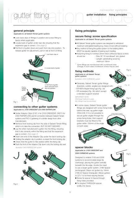
general principle<br />
Applicable to: all Geberit Terrain gutter <strong>systems</strong><br />
■ Lock back clips of fittings in position and screw fitting to<br />
fascia where applicable.<br />
■ Locate back of gutter under rear clip ensuring that the<br />
expansion gap is correct. (See page 2)<br />
■ Pull front of gutter down and push front clip into position. To<br />
release gutter for adjustment, pull on tab at front of fitting<br />
Fig 1.<br />
Pull to<br />
release<br />
gutter.<br />
Push to<br />
locate<br />
gutter in<br />
1. Lock back clips in<br />
2. Locate back of gutter<br />
3. Pull front of gutter<br />
down and push front<br />
clip into position.<br />
connecting to other gutter <strong>systems</strong><br />
Applicable to: 2100 CRESCENT and 2400 RAPIDFLOW<br />
■ Gutter Adaptor Clips (2167.4 for 2100 CRESCENT, 2467.5 for<br />
2400 RAPIDFLOW) permit connection between Geberit Terrain<br />
<strong>systems</strong> and PVC-U guttering of a similar design from other<br />
manufacturers<br />
■ Remove front locking clip from the side of Geberit Terrain fitting<br />
which is to take the connection, BUT DO NOT DISCARD<br />
■ Lay the other manufacturer’s gutter into the fitting, ensuring<br />
that it sits correctly within the fitting and that the expansion<br />
gap is correct. (See page 2)<br />
■ Insert one end of the Adaptor Clip under the back locking clip<br />
■ Holding the adaptor clip in position, re-insert the front locking clip<br />
■ Check that the gutter is fully seated within the fixing clip<br />
■ Push the front of the Adaptor Clip down onto the locking clip seat<br />
Illustrated: 2400 RAPIDFLOW system<br />
Fig 2.<br />
5<br />
fixing principles<br />
secure fixing: screw specification<br />
Applicable to: all Geberit Terrain gutter <strong>systems</strong><br />
■ All Geberit Terrain gutter <strong>systems</strong> are designed to withstand<br />
maximum anticipated loading (e.g. heavy snow) without breaking<br />
■ Any method of fixing the gutter system to the building fabric<br />
MUST be equally capable of bearing such loading<br />
■ Assuming fixing to nominal 25mm thick softwood fascia screws<br />
should be: - Size: Nº 10 roundhead* zinc-plated<br />
- Length: penetrating wood by<br />
minimum 19mm<br />
fixing methods<br />
Applicable to: all Geberit Terrain<br />
gutter <strong>systems</strong><br />
Illustrated: 2200 CORNICHE system<br />
■ Generally, Geberit Terrain gutter fittings<br />
(brackets, outlets, angles) are designed with:<br />
- EITHER integral fixing lugs (Fig. 3a)<br />
- OR recess(es) (Fig. 3b) which accept<br />
a standard support bracket<br />
IMPORTANT NOTE:<br />
Whichever method is used,<br />
ALL fittings must be anchored<br />
■ In some cases, Geberit Terrain gutter<br />
fittings are designed with screw fixing holes<br />
behind the seal, eg gutter angle<br />
2354.6.90. If it is not possible to<br />
secure gutter angles through the<br />
screw fixing holes, then support<br />
brackets must be fitted to the<br />
gutter within 150mm of the angle<br />
on both sides<br />
150mm<br />
spacer blocks<br />
gutter <strong>installation</strong> fixing principles<br />
* Some fittings are manufactured with countersunk holes<br />
(Omega). In such cases countersunk screws may be used<br />
Applicable to: 2100 CRESCENT and<br />
2200 CORNICHE <strong>systems</strong><br />
Designed to enable 2100 and 2200<br />
<strong>systems</strong> to accommodate large tile<br />
overhangs, placing the gutter centrally<br />
beneath the tile edge. Avoids the need<br />
to use a larger gutter system. 2166 Spacer<br />
(rectangular): Steps out gutters by 16mm<br />
2166.22 Spacer (triangular): Allows gutters<br />
to 22 1 /2° to be fixed sloping fascias<br />
■ Screw fix spacer to fascia through<br />
fixing holes provided<br />
■ Fix bracket THROUGH spacer,<br />
solidly into fascia<br />
Lugs<br />
Recess<br />
Screw holes for internal<br />
angle behind seal<br />
150mm<br />
Fig 3.<br />
Fig. 3a<br />
Fig. 3b<br />
Fig 4.<br />
Fig 5.