Imax condensing boilers - CMS
Imax condensing boilers - CMS
Imax condensing boilers - CMS

Create successful ePaper yourself
Turn your PDF publications into a flip-book with our unique Google optimized e-Paper software.
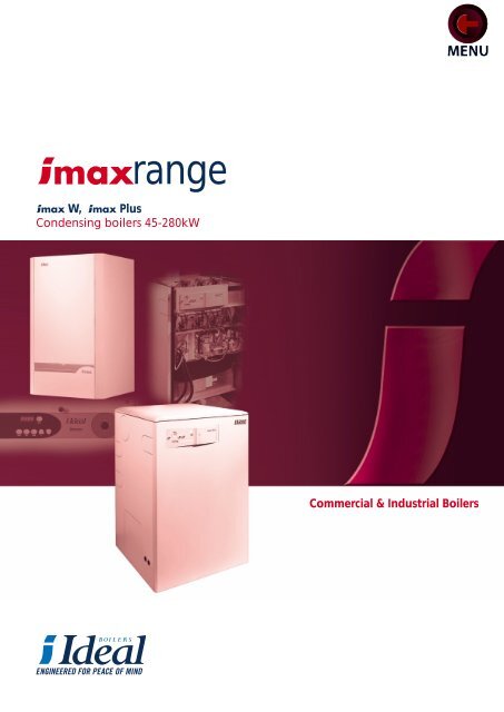
ange<br />
W, Plus<br />
Condensing <strong>boilers</strong> 45-280kW<br />
Commercial & Industrial Boilers
2<br />
the range<br />
Contents<br />
Introduction 3<br />
The Range 4 - 5<br />
Product specification 6 - 9<br />
Option kits 10 - 11<br />
Flueing 12 - 15<br />
System requirements 16 - 19<br />
General & performance data 20 - 21<br />
Dimensional data 22 - 23<br />
W<br />
Plus
Introduction<br />
Customers increasingly demand higher efficiencies and lower emissions from the heating plant. All this must be achieved in ever smaller<br />
dimensions. Ideal now provide a range of solutions with the high efficiency <strong>condensing</strong> wall hung <strong>boilers</strong> and Plus floor standing range.<br />
W<br />
The Ideal W wall mounted boiler comes in a range of outputs<br />
45, 60 or 80kW and all are capable of being installed as a single<br />
unit or in simple modular formations for even bigger outputs. The<br />
W is a highly efficient fully <strong>condensing</strong> boiler - up to 98%<br />
efficient nett (88.5% gross) non <strong>condensing</strong> and an impressive<br />
108% nett (97.3% gross cv) at 30% load, fully <strong>condensing</strong>. Even<br />
higher efficiencies are achieved at lower system temperatures. The<br />
fully modulating gas/air design ensures that maximum efficiency is<br />
maintained down to very low loads reflecting the needs of modern<br />
systems. At its heart is a robust cast aluminium heat exchanger<br />
providing a compact, space saving design making this the ideal<br />
boiler for plant rooms where space is at a premium.<br />
modulation to low outputs for<br />
high operating efficiencies<br />
Ideal <strong>boilers</strong> are fan assisted and have been designed with<br />
siting flexibility in mind. Flues can be concentric, twin duct, room<br />
sealed or open flued in single or multiple installations. It is one of<br />
the easiest commercial boiler ranges to install and service.<br />
The premix burner design ensures the lowest level of emissions. The<br />
range has been approved to the most stringent European Standards<br />
governing safety and performance of commercial <strong>boilers</strong> and is<br />
classified as low NOx (Class 5).<br />
The Ideal W incorporates an advanced microprocessor based<br />
control system which operates all electrical functions of the boiler<br />
including ignition, flame detection, temperature control and burner<br />
modulation. In addition the system has full commissioning and fault<br />
diagnostic displays.<br />
The <strong>boilers</strong> are offered with an extensive range of option kits<br />
including flues, system controls and modular header kits for<br />
maximum flexibility and ease of specification.<br />
Plus<br />
The Plus extends the Ideal <strong>condensing</strong> boiler range with<br />
outputs from 80kW to 280kW in a range of six compact floor<br />
standing <strong>boilers</strong> and can be installed in multiple formation to provide<br />
even larger outputs if the system requires.<br />
High efficiencies are the norm for <strong>boilers</strong> and the Plus<br />
is up to 96.6% efficient nett (87% gross cv) non-<strong>condensing</strong>, and<br />
108.4% nett (97.7% gross cv) at 30% load. Even higher efficiencies<br />
are achieved at lower temperatures. The fully modulating gas/air<br />
design ensures maximum efficiency is maintained down to as low as<br />
11.6kW output. This class-leading figure is achieved even with the<br />
largest model as the unique Plus design optimises load<br />
matching. The robust cast aluminium heat exchanger comprises of<br />
several sections, each flueway or module has its own burner fan, gas<br />
valve, ignition and safety controls and after all have modulated down<br />
to their combined minimum, modules are switched off to further<br />
match a reducing system load. Wasteful on/off cycling is reduced to<br />
the absolute minimum with the Plus, and a further benefit is<br />
that standby support is built into the design.<br />
Plus <strong>boilers</strong> are designed for ease of installation and the flue<br />
can be positioned to left, right or rear, whilst system and gas<br />
connections can be made to left or right of the boiler. All to ensure<br />
boiler house siting is as simple and fast as possible.<br />
Naturally the range meets the most stringent European Standards<br />
governing safety and performance and is classified as low NOx (Class<br />
5). It is also the quietest boiler of its size at less than 50dBA.<br />
The Plus uses advanced microprocessor based controls to<br />
operate all electrical functions and provides full commissioning and<br />
fault diagnostic displays. Furthermore it takes into account each<br />
modules’ operating hours and evens out their usage. Further benefits<br />
are that Hours Run Meters and BMS control is built-in as standard,<br />
whilst an outside sensor for weather compensation is supplied with<br />
each boiler.<br />
Conforms with all relevant<br />
European standards and<br />
requirements<br />
3
4<br />
the range<br />
W 45 - 80kW<br />
• High operating efficiencies with close load matching<br />
• Natural gas and propane<br />
• Single unit or modular configuration, wall or frame mounted<br />
• Wide modulating output range from 13 - 80kW<br />
• Robust cast aluminium heat exchanger<br />
• Integral commissioning and fault diagnostics<br />
The W<br />
control panel<br />
• Flue flexibility, concentric and twin duct, room sealed or open<br />
flue applications<br />
• Easy to install and service<br />
• Simple UK voltage system controls wiring<br />
• Comprehensive control options<br />
• Meets Building Regulations 2000 (Part L)
The Plus<br />
control panel<br />
(F120 shown)<br />
• Range of six models from 80 - 280kW<br />
• Compact size - small footprint<br />
Plus 80 - 280kW<br />
• High modulation - Close load matching (all models down to<br />
11.6kW)<br />
• 108.4% Net efficiency (fully <strong>condensing</strong>) at 30% part load<br />
• Boilers consist of several modules giving built-in standby<br />
capability<br />
• Robust cast aluminium heat exchanger<br />
• Integral commissioning and fault diagnostics<br />
• Optional flue and system connections for fast installations<br />
• Meets Building Regulations 2000 (Part L)<br />
5
6<br />
product specification<br />
Performance<br />
The Ideal range offers high operating efficiencies,<br />
together with the lowest possible emissions, and is certified to<br />
comply with the Gas Appliance Directive (90/396) and the Boiler<br />
Efficiency Directive (92/42), the European Directives governing<br />
safety and performance of gas <strong>boilers</strong> ensuring high quality<br />
performance.<br />
The design of the boiler ensures high efficiencies at both full<br />
and part loads to meet the new ‘Building Regulations 2000’<br />
conservation of fuel and power. Approved efficiencies are up to 98%<br />
at 80˚C flow based on net calorific value of fuel (88.5% gross) at full<br />
load. At 30% part load the efficiencies exceed 108% net (97.3%<br />
gross).<br />
Boiler Range Certificate No. Notified Body Reference<br />
W W45 - 80 0063BN3218I Gastec NV 0063<br />
Plus F80 - 280 49BM3615 AFNOR, Paris 0049<br />
In order to give you assurance and peace of mind a Certification of<br />
Compliance to the Building Regulations 2000 can be obtained from<br />
the commercial heating department.<br />
Boiler Operation<br />
W<br />
On a call for heat, air is drawn into the boiler variable speed fan.<br />
The fan inlet incorporates a special mixing arrangement for gas<br />
supplied from the gas valve. The gas/air mixture is automatically<br />
ignited at low rate beneath the burner via a spark electrode and<br />
ignition proved by a flame rectification electrode. The flue gases pass<br />
downwards through the heat exchanger and via the sump and flue<br />
outlet to atmosphere. A plume of vapour will be visible at the<br />
terminal due to the low exit temperature.<br />
The boiler modulates its output according to demand via the<br />
flow/return sensors and any external controls. The fan speed and gas<br />
flow are adjusted under this electronic control to provide the correct<br />
mixture and output. This maintains high efficiency part loads.<br />
Condensation within the boiler will start to occur when the<br />
return temperature is below the dew point (55˚C). The flue gases will<br />
condense and increase boiler efficiency by giving up their latent heat<br />
to the system. Condensation formed within the boiler is removed via<br />
the integral drain.<br />
Plus<br />
When the boiler receives a call for heat, the boiler control<br />
Modular Boiler Drive (MBD) calculates the necessary output<br />
according to the difference between the set flow temperature (or<br />
compensated flow temperature for a CH call when using an outside<br />
sensor) and the boiler modules’ combined flow temperature. The first<br />
module fan operates and the gas/air mixture is automatically ignited<br />
below the burner via a spark electrode and proved by a detection<br />
electrode. Ignition occurs in 5 seconds and once detected the<br />
module starts operating. Subsequently, additional modules will fire<br />
to provide the load required.<br />
The boiler principle method of operation is to run as many<br />
modules simultaneously, at the lowest possible load, for maximum<br />
efficiency e.g.<br />
If an F160 with 160kW max. output is only requested to provide<br />
72kW.<br />
72 / 4 = 18kW per module<br />
Therefore, the boiler operates all modules at the reduced rate of<br />
18kW. If the required load is less than the min. 12kW per module,<br />
then one module after the other will automatically shut down and the<br />
load shared by the remaining modules. The modules with the lowest<br />
number of hours run are automatically chosen to satisfy the demand.<br />
Electrical Controls<br />
The <strong>boilers</strong> incorporate an advanced microprocessor based<br />
control system which operates all electrical functions of the boiler<br />
including ignition, flame detection, flow/return temperature sensors<br />
and output modulation. In addition the microprocessor displays<br />
boiler status and a fault diagnosis program.
System Application<br />
Ideal <strong>boilers</strong> are designed for central heating of large<br />
domestic and commercial premises and also for supplying domestic<br />
hot water via a calorifier or plate heat exchanger. They are suitable<br />
for fully pumped, open vented or pressurised systems and can be<br />
connected to heating and/or domestic hot water systems.<br />
They are not suitable for direct hot water supply or gravity<br />
heating/hot water systems.<br />
W Plus<br />
Maximum static head: 40.7 metres 61 metres<br />
(134 feet) (200 feet)<br />
Maximum working pressure: 4 bar 6 bar<br />
(58.7psi) (87psi)<br />
Maximum design flow temperature is 82˚C (180f)<br />
(This is adjustable to 90˚C if required at the control panel).<br />
Pump overrun is provided as standard, and a period of 5 minutes<br />
must be allowed for in system design.<br />
Frost protection is built into the boiler control, if the boiler sensor<br />
falls below 7˚C, this will result in the appliance firing.<br />
This will protect the boiler only, not exposed system elements.<br />
Packing<br />
The Ideal is despatched from works in separate packs<br />
as follows:<br />
W contains: Plus contains:<br />
Complete boiler Assembled boiler body<br />
with separate:- Casing pack<br />
Flue option packs Condensate pipe & fixings<br />
Control option packs Flue manifold, socket & gasket<br />
Modular header kits Outside sensor pack<br />
A full commissioning service is available at an extra charge.<br />
Quality<br />
As with all Ideal <strong>boilers</strong>, the W & Plus <strong>boilers</strong> are<br />
engineered to the highest quality standards. Ideal Boilers products<br />
meet or exceed the requirements of all relevant standards. Before<br />
despatch each boiler is fired and fully tested. The control valves are<br />
also adjusted to give the correct gas flow rate. Ideal Boilers are<br />
recognised as a World Class Manufacturer.<br />
assurance of quality<br />
BS EN ISO 9001: 2000<br />
7
8<br />
product specification<br />
(W80 model shown)<br />
W Boiler Construction<br />
Ideal W wall mounted <strong>boilers</strong> are constructed from cast<br />
aluminium heat exchangers with tubular steel flow and return manifolds.<br />
The heat exchanger is mounted in a sealed white enamelled<br />
steel casing.<br />
A premix downfiring burner is mounted above the heat exchanger.<br />
W45 & W60<br />
A cast aluminium sump is fitted below with condensate drain<br />
connection.<br />
The concentric flue outlet and air inlet is positioned on the<br />
boiler top, with gas and system connections at the base.<br />
Controls are accessible behind a drop down door. Maintenance<br />
and servicing is all achieved from the boiler front.<br />
1. Jacket side panel<br />
2. Jacket front panel assy.<br />
3. Controls fascia<br />
4. Controls door assy.<br />
5. Wall mounting plate<br />
6. Internal flue tube<br />
7. Air pressure switch<br />
8. Fan<br />
9. Mounting plate manifold<br />
10. Gas valve<br />
11. Upper gas pipe<br />
12. Lower gas pipe<br />
12A. Gas pipe<br />
13. Sight glass complete<br />
14. Ignition/detection electrode<br />
15. Auto air vent<br />
16. Manifold flow<br />
17. Heat exchanger assy.<br />
18. Inspection cover assy.<br />
19. Condensate outlet pipe<br />
20. Manifold return<br />
21. Thermistor flow or return<br />
22. Transformer<br />
23. Control module<br />
24. Pressure gauge<br />
25. Water pressure switch<br />
31. Gas manifold
Plus Boiler Construction<br />
The construction of the Plus sectional heat exchanger<br />
design is of cast aluminium. Individual downfiring burners, fans, gas<br />
valves and ignition safety controls for each flueway or module are<br />
provided. A non-return valve ensures no reverse circulation of flue<br />
products through modules not operating. A stainless steel sump<br />
collects the flue products and diverts them to the flue, whilst<br />
allowing drainage of condensate products.<br />
9
10<br />
option kits<br />
Option Kits<br />
The boiler range comes with a host of options designed to<br />
give greater flexibility and control to your heating system.<br />
Modulating sequencer kit ✓<br />
Programmable room thermostat kit ✓<br />
Control interface kit ✓<br />
Outside sensor kit ✓ *<br />
Tank sensor kit ✓ ✓<br />
Remote indication kit ✓ *<br />
Hours run meter(s) * *<br />
BMS (0-10V) kit ✓ *<br />
Pump kit ✓<br />
Multi boiler frame and header kits ✓<br />
*Provided as standard<br />
W Plus<br />
Control Interface Kit Remote Indication Kit Programmable Room<br />
Thermostat Kit<br />
Tank Sensor Kit BMS (0-10v) Kit Outside Sensor Kit<br />
W Flue Kits<br />
Horizontal wall flue kit A range of concentric flue pipes<br />
together with wall mounted grille for<br />
horizontal flue applications.<br />
Vertical roof flue kit A range of concentric flue pipes<br />
together with terminal grille for roof<br />
flue applications.<br />
Twin pipe flue kits Air and flue pipe terminals for extra<br />
long runs using twin ducts.<br />
Open flue kit A range of air inlet grilles for direct<br />
installation to the boiler with flue<br />
connection.<br />
For more information see Flueing page 12.<br />
Modulating Sequencer Kit<br />
Flue Options
W Multiple Boiler Kit Installations<br />
W <strong>boilers</strong> are also designed for multiple boiler installations.<br />
Such installations can be an advantage in many situations:<br />
• Compact size means easier location, transportation and<br />
handling.<br />
• Close load matching means higher annual operating<br />
efficiencies.<br />
• Inherent reliability and service continuity. One boiler may be<br />
shut down for servicing whilst the remainder continue<br />
operating.<br />
• A sequencer kit and multiple boiler pipework kits are available<br />
for the W.<br />
The header kit comes complete with all the components<br />
necessary to complete a multiple installation:<br />
• Gas and water headers (2 or 3 <strong>boilers</strong>)<br />
• Mixing header<br />
• Individual flow, return and gas connection pipework<br />
incorporating isolating valves<br />
• All necessary mounting brackets for pipework<br />
Ideal W <strong>boilers</strong> are also designed for use with a boiler<br />
frame mounting kit which allows <strong>boilers</strong> to be mounted onto a free<br />
standing boiler frame rather than onto the wall.<br />
This frame mounting kit is especially useful when wall space is<br />
at a premium or wall condition is suspect. The frame mounting kit is<br />
suitable for use with installations of 1 or more <strong>boilers</strong>.<br />
W Multiple Boiler Frame Kit<br />
1. Frame kit<br />
2. 3 Blr. flow & return<br />
header kit<br />
3. 3 Blr. gas header kit<br />
4. Connection kit<br />
5. Mixing header<br />
6. Pump<br />
(For dimensions<br />
see page 22)<br />
1. Non-return valve<br />
2. Safety valve<br />
3. Service valve<br />
4. Expansion vessel<br />
5. Mixing header<br />
6. Flow sensor<br />
7. System pump<br />
8. Modulating<br />
Sequencer kit<br />
9. Flue gas terminal<br />
10. Room Temp. sensor<br />
11. Drain cock<br />
12. Outdoor sensor<br />
Plus Multiple Boiler Installations<br />
Plus <strong>boilers</strong> are suitable for installations where the load<br />
requires more than one boiler.<br />
e.g. 2 x F280 = 560kW or in larger multiples<br />
The flexibility of flue connection position (left, right or rear) and<br />
system and gas connections (left or right) allows multiple <strong>boilers</strong> to<br />
be sited more easily in confined boiler homes.<br />
Plus <strong>boilers</strong> can be laid out for example with rears<br />
towards each other and flues at the same end. Many more options<br />
are possible to minimise plant room area.<br />
11
12<br />
flueing<br />
Flue Systems<br />
To ensure safe and satisfactory operation, the boiler must be<br />
connected to a chimney system capable at all times of adequately<br />
evacuating the combustion products (see performance data table on<br />
page 14 for approximate volumes).<br />
The Ideal W & Plus <strong>boilers</strong> are suitable for use in<br />
both room sealed and open flue fan assisted operation. Connections<br />
for combustion air inlet and flue products discharge are located on<br />
the top of the appliance ( Plus: separate vertical flue outlet to<br />
left, right or rear, air inlet at left or right).<br />
concentric and<br />
twin duct systems<br />
The jacket of the Ideal <strong>condensing</strong> boiler is constructed<br />
such that it forms an air tight seal. It is therefore important that the<br />
jacket of the unit is fitted properly whilst the boiler is in operation.<br />
The boiler is suitable for use in either single or multiple flue<br />
configurations and can be fitted with a wide variety of flue systems.<br />
Horizontal flue runs MUST be inclined at 2.5˚ to the horizontal<br />
in order that any condensate formed can be discharged through the<br />
boiler.<br />
W Flue Kits<br />
W Only<br />
The flue kits are suitable for use with the Ideal boiler only.<br />
These kits and the associated options are suitable for both roof<br />
and wall mounting applications.<br />
Several flue options are available:<br />
• Horizontal flue kits (80/125mm or 100/150mm dia.)<br />
• Vertical roof flue kits (80/125mm or 100/150mm dia.)<br />
• Twin pipe flue kits<br />
• Open flue kits<br />
The twin pipe flue kit is suitable where particularly long flue<br />
runs are required and compact flue and air ducts are required.<br />
The roof kit is suitable for both flat and pitched roof termination,<br />
using a concentric flue (tube within tube) to run vertically from the<br />
top of the boiler and terminating above the roof level.<br />
If obstructions prevent direct flue routing then both 90˚ and 45˚<br />
elbows can be provided to offset any of the flue systems.<br />
Accessories<br />
Flue duct extension kits are available for flue lengths extending<br />
beyond 1 metre. These packs contain additional 1 metre ducts and<br />
may be cut to the desired length.<br />
Elbows, 90˚ and 45˚, are also available.<br />
W & Plus<br />
All joints or connections in the flue system must be impervious<br />
to condensate leakage and also any low points in the flue system<br />
should be drained using pipe of material resistant to condensate<br />
corrosion.<br />
The flue duct termination point must be positioned so that it will<br />
not be affected by adverse wind conditions and be free from any<br />
obstructions. Note: A vapour plume will be visible at the terminal.<br />
Therefore where possible terminal positions which could cause<br />
problems due to plumeing should be avoided.<br />
The use of a fan on the boiler permits long flue runs however,<br />
the resistance of bends etc will reduce the overall length. Full details<br />
of the W flue sizes and resistances can be found on page 13<br />
of this booklet.<br />
NO additional diverter, stabiliser, or draught break should be<br />
installed in the chimney system without prior consultation with<br />
Caradon Ideal Ltd.<br />
Flues and terminal positions should be designed with strict<br />
regard to the requirements of BS 5440: Part 1, BS 6644, IGE<br />
UP/10 and the Building Regulations Part J as appropriate. Particular<br />
attention should be paid to these for multiple boiler installations and<br />
if required, the Clean Air Act.<br />
Weatherproofing<br />
Where the flue passes through the roof line an adequate seal<br />
must be made. This can be achieved by using either:<br />
• Flat weather collar 125mm or 150mm<br />
• Pitched weather collar 125mm or 150mm<br />
Additional information covering selection and installation can be<br />
found within this guide.
W Flue Termination Position<br />
If the terminal is fitted less than 500mm below<br />
plastic gutters, painted eaves or any other painted<br />
surface then an aluminium shield at least 1m long<br />
should be fitted to protect the surface.<br />
Concentric Wall Terminal Positions Minimum spacing<br />
A. Below an opening (1) 300 mm 12 in<br />
B. Above an opening (1) 300 mm 12 in<br />
C. Horizontally to an opening (1) 300 mm 12 in<br />
D. Below gutters, soil pipes or drain pipes 75 mm 3 in<br />
E. Below eaves 200 mm 8 in<br />
F. Below balcony or car port roof 200 mm 8 in<br />
G. From a vertical drain pipe or soil pipe 150 mm 6 in<br />
H. From an internal or external corner or to a boundary alongside the terminal 300 mm 12 in<br />
I. Above ground, roof or balcony level 300 mm 12 in<br />
J. From a surface or a boundary facing the terminal 600 mm 24 in<br />
K. From a terminal facing the terminal 1200 mm 48 in<br />
L. From an opening in the car port into the building 1200 mm 48 in<br />
M. Vertically from a terminal on the same wall 1500 mm 60 in<br />
N. Horizontally from a terminal on the same wall<br />
Concentric Roof Terminal Positions<br />
300 mm 12 in<br />
Directly below an opening, air brick, windows, etc 300 mm 12 in<br />
Below plastic/painted gutters 500 mm* 20 in<br />
Below painted surface 500 mm* 20 in<br />
Below eaves or balcony 500 mm 20 in<br />
From wall 1000 mm 40 in<br />
* may be reduced to 300 mm if a shield fitted<br />
(1) An opening here means an openable element, such as an openable window, or a fixed opening such as an air vent. However, in addition, the outlet should not be nearer<br />
than 150 mm (fanned draught) to an opening into the building fabric formed for the purpose of accommodating a built in element, such as a window frame.<br />
Flue Data<br />
W Important - The boiler must be installed in a vertical position.<br />
The pressure available at the boiler outlet is sufficient to<br />
overcome the resistance of considerable flue lengths. The maximum<br />
straight length of concentric flue may be as long as 31.6 metres,<br />
dependent on model. A twin duct arrangement can be up to 29<br />
metres combined flue and air pipes, with small wall terminals.<br />
The maximum potential length for each flue type by boiler model<br />
is shown in the table opposite, although allowances must be made<br />
when elbows are used. The length to be subtracted for each elbow<br />
used is also provided in the table below.<br />
Maximum equivalent lengths (metres) W45 W60 W80<br />
Horizontal Wall Flue Kit 80/125 9.5 7.8 -<br />
Horizontal Wall Flue Kit 100/150 31.6 26 16<br />
Vertical Roof Flue Kit 80/125 9.5 7.8 -<br />
Vertical Roof Flue Kit 100/150 31.6 26 16<br />
Twin Pipe Flue Kit (W45 & W60 only)* 29 19 -<br />
Open Flue Kit 80 20 13.3 -<br />
Open Flue Kit 100<br />
* Maximum combined air and flue ducts<br />
- - 29<br />
Fitting equivalent lengths (metres) W45 W60 W80<br />
1 metre extension 80/125 1.0 1.0 -<br />
1 metre extension 100/150 1.0 1.0 1.0<br />
45˚ elbow 80/125 1.1 1.1 -<br />
45˚ elbow 100/150 1.2 1.2 1.2<br />
90˚ elbow 80/125 1.6 1.6 -<br />
90˚ elbow 100/150 2.0 2.0 2.0<br />
1 metre extension 80 dia. (Twin duct type) 1.0 1.0 1.0<br />
90˚ elbow 80 dia. (Twin duct type) Air tube 1.4 1.4 -<br />
90˚ elbow 80 dia. (Twin duct type) Flue tube 2.1 2.1 -<br />
45˚ elbow 80 dia. (Twin duct type) Air tube 0.4 0.4 -<br />
45˚ elbow 80 dia. (Twin duct type) Flue tube 0.6 0.6 -<br />
Plus<br />
Proprietary flue systems are available for use with this range. A<br />
pressure of 100Pa is available at the flue outlet.<br />
13
14<br />
flueing<br />
W Flue Designs<br />
Flue designs are calculated against the maximum available<br />
resistance using the flue data table on page 10. The examples<br />
provided are given as a guide only, therefore a greater number of<br />
variations can be obtained<br />
Example of Calculating Flue Resistance/Lengths -<br />
Horizontal Concentric Flue<br />
Horizontal flue for W45 (80/125 dia.)<br />
Part No. Lengths (m)<br />
Maximum equivalent length 9.5<br />
Horizontal wall flue kit 80/125 158659<br />
2 x 1m extension flue 152400 2<br />
1 x 90˚ elbow 152616 1.6<br />
Total length reduction 3.6<br />
The total equivalent length reduction is 3.6 metres, which is less than the<br />
maximum length possible of 9.5m. Therefore this arrangement is<br />
satisfactory.<br />
Example of Calculating Flue Resistance/Lengths -<br />
Vertical Concentric Flue<br />
Vertical Roof flue for W60 (80/125 dia.)<br />
Part No. Lengths (m)<br />
Maximum equivalent length 7.5<br />
Vertical flue kit 80/125 158654<br />
2 x 1m extension flue 152400 2<br />
2 x 45˚ elbows 152618 2.2<br />
Total length reduction 4.2<br />
The total equivalent length reduction is 4.2 metres, which is less than the<br />
maximum length possible of 7.5m. Therefore this arrangement is<br />
satisfactory.
W Flue Designs<br />
Example of Calculating Flue Resistance/Lengths -<br />
Open Flue<br />
Open flue for W60 (80 dia.)<br />
Part No. Lengths (m)<br />
Maximum equivalent length 13.3<br />
Open flue kit 80 158662<br />
Vertical flue terminal 80 158769<br />
2 x 1m twin extension pipes 80 158771 2.0<br />
2 x 45˚ elbows 80 158775 2.0<br />
Total length reduction 4.0<br />
The total equivalent length reduction is 4.0 metres, which is less than the<br />
maximum length possible of 13.3m. Therefore this arrangement is<br />
satisfactory and a longer flue length is possible if required.<br />
Example of Calculating Flue Resistance/Lengths -<br />
Twin Duct<br />
Horizontal flue terminal 80<br />
Twin Duct for W45 & W60(80 dia.)<br />
Part No.<br />
158777<br />
Horizontal air terminal 80 158778<br />
1m flue extension pipes 80 (pair) 158771<br />
90˚ elbow 80 158773<br />
Calculation<br />
1. Air pipe length Y = 8.5m.<br />
2. Refer to graph below and plot vertical line on air axis at 8.5m as shown.<br />
Where vertical line intersects the bold W45 line, read off maximum<br />
allowable flue length.<br />
In this example maximum straight flue pipe length is 14m.<br />
3. Bend allowance to be subtracted from flue length.<br />
In this example is 2 x 90˚ bends = 2 x 3.5m = 7m.<br />
Therefore X = 14 - 7 = 7 metres max. flue pipe.<br />
15
16<br />
system requirements<br />
Open Systems<br />
The system should be vented directly off the boiler flow pipe, as<br />
close to the boiler as possible. The cold feed entry should be<br />
inverted and MUST be positioned between the pump and the vent,<br />
and not more than 150mm (6”) away from the vent connection.<br />
There should be a minimum height, 500mm (20”) of open vent<br />
above the cistern water level. The vertical distance between the<br />
highest point of the system and the feed/expansion cistern water<br />
level MUST not be less than 3 metres.<br />
The information provided is based on the following assumptions:<br />
The boiler is at the highest point of the circulation system.<br />
Systems designed to raise above the flow tappings will, of course,<br />
automatically require a minimum static head higher than shown.<br />
The position of the open vent/safety pipe above the expansion<br />
cistern water level is given as a guide only. The final position will<br />
depend upon particular characteristics of the system. Pumping over<br />
of water into the expansion cistern should be avoided.<br />
Cold Feed/Open Vent<br />
The independent cold feed and the open vent must comply with<br />
BS 6644 and be of the following minimum size:<br />
Boiler output (kW) Cold feed Open vent<br />
45 – 60<br />
61 - 150<br />
151 - 300<br />
3 /4” (19mm)<br />
1” (25mm)<br />
1 1 /4” (32mm)<br />
1” (25mm)<br />
1 1 /4” (32mm)<br />
1 1 /2” (38mm)<br />
* Plus only: For head heights less than 8m the pump must be<br />
fitted on the return.<br />
Sealed (Pressurised) Systems<br />
W<br />
Working pressure 4 bar (58psi) maximum.<br />
Plus<br />
Working pressure 6 bar (87psi) maximum.<br />
Particular reference should be made to BS 6644: Section 2;<br />
Subsection 11, Guidance note PM5 “Automatically controlled steam<br />
and hot water <strong>boilers</strong>” published by the Health and Safety Executive<br />
and Water Regulations Guide.<br />
The information and guidance given below is not intended to<br />
override any requirements of either of the above publications or the<br />
requirements of the Local Authority, gas or water undertakings.<br />
In general, commercial closed pressurised systems are provided<br />
with either manual or automatic water make up.<br />
In both instances it will be necessary to fit automatic controls<br />
intended to protect the boiler circulating system and ancillary<br />
equipment by shutting down the boiler plant if a potentially<br />
hazardous situation should arise.<br />
Examples of such situations are low water level and operating<br />
pressure or excessive pressure within the system. Depending on<br />
circumstances, controls will need to be either manual or automatic<br />
reset. In the event of shut down, both visual and audible alarms may<br />
be necessary.<br />
Pressure vessels used must comply with BS 4814 and must<br />
be sized on the basis of the total system volume and initial<br />
charge pressure.<br />
Initial minimum charge pressure should not be less than 0.5 bar<br />
(7.2psi) and must take account of static head and specification of<br />
the pressurising equipment. The maximum water temperatures<br />
permissible at the point of minimum pressure in the system is<br />
specified in Guidance Note PM5.<br />
When make up water is not provided automatically it will be<br />
necessary to fit controls which shut down the plant in the event of<br />
the maximum system pressure approaching to within 0.35 bar (5psi)<br />
of the safety valve setting.<br />
Other British Standards applicable to commercial sealed<br />
systems are:<br />
BS 6880: Part 2<br />
BS 1212<br />
BS 6281: Part 1<br />
BS 6282: Part 1<br />
BS 6283: Part 4
System Design<br />
The efficiency of this range of <strong>boilers</strong> is higher than conventional<br />
<strong>boilers</strong> because of the increased heat exchange area.<br />
At return temperatures of 55˚C and below, the differences<br />
become more marked because the water in the flue gases starts to<br />
condense releasing its latent heat.<br />
Installation<br />
For safety, a competent CORGI (Council for the Registration of<br />
Gas Installers) registered installer must fit this appliance. CORGI<br />
requires its members to work to satisfactory standards.<br />
Boiler installation should comply with relevant British Standard<br />
Specifications, Codes of Practice, and current Building Regulations,<br />
together with any special regional requirements of the Local<br />
Authorities, Gas Supplier, and Insurance Company, and in particular:<br />
BS 6891 Low Pressure Installation Pipes, BS 6644 Installation<br />
of Gas Fired Boilers, BS 6880 Part 1-3 Central Heating by Low<br />
Pressure Hot Water, CP 342.2 Centralised Hot Water Supply,<br />
IGE/UP/10 Installation of Gas Appliances in Industrial & Commercial<br />
Premises, Part 1: Flued appliances.<br />
In general, the lower return temperature, the better the efficiency.<br />
In new systems it is best to design for the lowest flow and return<br />
temperatures that are practical (subject to the lower limit mentioned<br />
above). For optimum operation it is advised that the system be<br />
designed on a temperature differential of 20˚C.<br />
All electrical wiring must comply with lEE Regulations.<br />
Manufacturer’s notes must not be taken as overriding statutory<br />
obligations.<br />
Minimum clearances from walls or other fixed objects to allow<br />
for installation, maintenance, and the free access of combustion air<br />
are shown in the boiler clearance diagram.<br />
17
18<br />
system requirements<br />
Water Treatment<br />
Corrosion will always occur within a heating/hot water system to<br />
a greater or lesser degree irrespective of water characteristics, unless<br />
the initial fill water from the mains is treated. For these reasons Ideal<br />
Boilers Solutions strongly recommends that when necessary the<br />
system be thoroughly cleaned prior to the use of a stable inhibitor<br />
which does not require continual topping up to combat the effects of<br />
hardness, salts and corrosion on the heat exchanger and its<br />
associated systems.<br />
The Ideal W & Plus <strong>boilers</strong> have an aluminium alloy<br />
heat exchanger. Therefore it is important that if water treatment is<br />
used it is suitable for the material of the heat exchanger. The ONLY<br />
water treatments approved are ‘Fernox Copal’ and ‘Sentinel X 100’.<br />
Current suitability should be confirmed with the manufacturer direct:<br />
BetzDearborn Ltd, Sentinel Division, Foundry Lane, Widnes,<br />
Cheshire WA8 8UD Telephone: 0151 424 5351 or Fernox, Fry<br />
Technology UK, Tandem House, Marlowe Way, Beddington Farm<br />
Road, Croydon CRO 4XS Telephone: 01799 550811 for technical<br />
information.<br />
Any other treatment used will render the guarantee of Caradon<br />
Ideal Limited for this product INVALID. The use of artificially<br />
softened water is NOT permitted.<br />
Gas<br />
W & Plus<br />
Natural Gas models: If there is any doubt concerning the<br />
capacity of the gas meter, available gas pressure, adequacy of<br />
existing pipes or the size required for new service pipes, contact the<br />
Gas Region for advice. Installation pipework should be fitted and<br />
tested for gas soundness in accordance with BS 6891. The local Gas<br />
Region must be consulted if a gas pressure booster is needed.<br />
W Only<br />
Propane Gas models: Contact the local Propane Gas supplier at<br />
the installation planning stage to ensure availability of an adequate<br />
supply of gas. Installation pipes, cylinders and pressure regulators<br />
should be fitted in accordance with BS 5482: 1. Bulk tank<br />
installations must comply with the Home Office Codes of Practice for<br />
the storage of LPG at fixed installations.<br />
Ventilation<br />
Open flued application<br />
Safe, efficient, and trouble-free operation of conventionally flued<br />
gas <strong>boilers</strong> is vitally dependent on the provision of an adequate<br />
supply of fresh air to the room in which the appliance is installed.<br />
Ventilation by grilles communicating directly with the outside air<br />
is required at both high and low levels. The minimum free areas of<br />
these grilles must be according to the scale below. The use of an<br />
extractor fan in the same room as the boiler (or in an adjacent room<br />
in communication) can, in certain conditions, adversely affect the<br />
safe operation of the boiler. Where such a fan is already fitted, or if<br />
an extractor fan is likely to be installed at a later date, then the<br />
advice of the gas supplier should be obtained.<br />
W45 & W60 Only<br />
BS 5440: 2 - Inputs not exceeding 70kW (nett)<br />
Total nett input Air vent areas<br />
rating of <strong>boilers</strong> (air direct from outside)<br />
Up to 70kW 5cm 2 per kW nett input<br />
Total gross input Position of Air vent areas<br />
rating of <strong>boilers</strong> air vents (air direct from outside)<br />
270cm 2 plus 2.25cm 2<br />
60kW to 2MW High level per kW in excess of<br />
60kW total rated input<br />
540cm 2 plus 4.5cm 2<br />
W & Plus<br />
BS 6644 - Inputs greater than 60kW (gross)<br />
60kW to 2MW Low level per kW in excess of<br />
60kW total rated input<br />
Balanced flue applications<br />
Room sealed installations require no air for combustion as this is<br />
drawn direct from the outside atmosphere. However, air may be<br />
required to ventilate the boiler house and remove any excess heat<br />
generated by the boiler.<br />
available.<br />
W <strong>boilers</strong> have a standard range of balanced flues<br />
Plus <strong>boilers</strong> have an air inlet connection which may be<br />
used with proprietary ducting if required. A separate flue connection<br />
is still required.
Condensate Drain<br />
Ideal <strong>boilers</strong> will produce condensate whenever the<br />
temperature of the return water from the system is below<br />
approximately 55˚C (the dew point of the combustion products).<br />
Natural Gas condensate is mildly acidic with a pH value of about<br />
4 and therefore corrosion resistant materials must be used in the<br />
construction of the condensate drain. Standard PVC pipe is suitable<br />
for this purpose and should be connected to the plastic drain fitted<br />
on the boiler.<br />
Plus Condensate Drain<br />
W<br />
A condensate trap is supplied for fitting to the boiler and the<br />
drain may be led directly into the normal drainage system. The pipe<br />
should be installed with an adequate slope (eg 1 in 50) and<br />
consideration should be given to frost protection.<br />
Plus<br />
Pipework is supplied for fitting beneath the boiler and includes a<br />
filling point for initial charging of a condensate siphon (not<br />
supplied). The pipe should be installed with an adequate slope (eg 1<br />
in 50) and consideration should be given to frost protection.<br />
19
general & performance data<br />
General Data - W (45 - 80)<br />
Model W45 & W45P W60 & W60P W80 & W80P<br />
Flow connection BSP R1 1 ⁄4”<br />
Return connection BSP R1 1 ⁄4”<br />
Maximum static water head<br />
Maximum pressure<br />
Performance Data - W (45 - 80)<br />
Model W45 W45P W60 W60P W80 W80P<br />
Boiler output (<strong>condensing</strong>)<br />
max<br />
kW<br />
Btu/h<br />
46.9<br />
160,000<br />
45.9<br />
156,000<br />
62.3<br />
212,560<br />
60.6<br />
206,750<br />
82.7<br />
282,170<br />
80.0<br />
272,950<br />
50/30˚C<br />
min<br />
kW<br />
Btu/h<br />
13.9<br />
47,600<br />
13.7<br />
46,600<br />
13.9<br />
47,600<br />
13.6<br />
46,400<br />
21.3<br />
72,700<br />
20.7<br />
70,600<br />
Boiler output (non-<strong>condensing</strong>)<br />
max<br />
kW<br />
Btu/h<br />
43.7<br />
149,000<br />
58.9<br />
200,960<br />
78.2<br />
266,800<br />
80/60˚C<br />
min<br />
kW<br />
Btu/h<br />
12.6<br />
43,000<br />
12.6<br />
43,000<br />
19.5<br />
66,500<br />
Boiler input (Nett)<br />
Boiler input (Gross)<br />
max<br />
min<br />
max<br />
min<br />
Gas rate Natural Gas<br />
Gas rate Propane<br />
m 40.79<br />
ft 133.83<br />
Bar 4.0<br />
psi 58<br />
Gas inlet connection mm 22<br />
Pressure required at the boiler inlet mbar 17.5<br />
for the rated input (Natural Gas) in. w.g. 7.0<br />
Electricity supply 230V 50Hz<br />
Nominal flue size / concentric mm 80 / 125 80 / 125 100 / 150<br />
Nominal flue size / twin pipe mm 80 / 80 80 / 80 100 / 100<br />
Condensate drain mm 25<br />
NOx emissions<br />
Water content<br />
mg / kW / hr 45 55 60<br />
ppm (0% O 2 ) 26 31 34<br />
l 8 8 10<br />
gal 1.76 1.76 2.20<br />
Weight<br />
kg<br />
lb<br />
87<br />
191<br />
88<br />
194<br />
101<br />
222<br />
Power consumption W 51 84 120<br />
kW 45 60 80<br />
Btu/h 153,540 204,720 272,960<br />
kW 13 13 20<br />
Btu/h 44,350 44,350 68,240<br />
kW 49.9 48.9 66.5 65.1 88.7 86.9<br />
Btu/h 170,250 166,850 227,000 222,300 302,700 296,350<br />
kW 14.4 14.1 14.4 14.1 22.2 21.7<br />
Btu/h 49,150 48,150 49,150 48,150 75,650 74,100<br />
m 3 /h 4.76 6.35 8.46<br />
ft 3 /h 166 222 296<br />
m 3 /h 1.84 2.45 3.27<br />
ft 3 /h 65 86 115<br />
Approx flue gas volume<br />
Natural Gas<br />
m 3 (non <strong>condensing</strong>) max rate<br />
/s<br />
ft<br />
0.02 0.027 0.036<br />
3 /min 42.33 57.67 77<br />
Approx flue gas volume<br />
Propane<br />
m 3 (non <strong>condensing</strong>) max rate<br />
/s<br />
ft<br />
0.019 0.026 0.034<br />
3 /min 40 54.67 72.33<br />
Seasonal efficiency *(SEDBUK) % 90.4 91.3 90.4 92.1 90.2 91.6<br />
Note: Gas rates are calculated using a C.V. of 37.8 MJ/m 3 gross (34 MJ/m 3 nett) for Natural Gas or 95.7 MJ/m 3 for Propane.<br />
* The value is used in the UK Government’s Standard Assessment Procedure (SAP) for energy rating of dwellings.<br />
20
General Data - Plus (80 - 280)<br />
Model F80 F120 F160 F200 F240 F280<br />
Flow connection BSP R2”<br />
Return connection BSP R2”<br />
Maximum static water head<br />
Maximum pressure<br />
Performance Data - Plus (80 - 280)<br />
m 61<br />
ft 200<br />
Bar 6<br />
psi 87<br />
Gas inlet connection BSP R11 ⁄2”<br />
Pressure required at the boiler inlet mbar 15.0<br />
for the rated input (Natural Gas) in. w.g. 6.0<br />
Electricity supply 230V 50Hz<br />
Nominal flue size mm 150 150 150 200 200 200<br />
Nominal air inlet size mm 150 150 150 150 150 150<br />
Condensate drain mm 40<br />
NOx emissions<br />
Water content<br />
mg / kW / hr < 62<br />
ppm (0% O 2 ) < 35<br />
Model F80 F120 F160 F200 F240 F280<br />
Boiler output (<strong>condensing</strong>)<br />
max<br />
kW<br />
Btu/h<br />
83.9<br />
286,300<br />
125.9<br />
429,600<br />
167.8<br />
572,550<br />
209.8<br />
715,850<br />
251.8<br />
859,200<br />
293.7<br />
1,002,150<br />
Mean 50/30˚C<br />
min<br />
kW<br />
Btu/h<br />
13.0<br />
44,350<br />
13.0<br />
44,350<br />
13.0<br />
44,350<br />
13.0<br />
44,350<br />
13.0<br />
44,350<br />
13.0<br />
44,350<br />
Boiler output (non-<strong>condensing</strong>)<br />
max<br />
kW<br />
Btu/h<br />
77.3<br />
263,750<br />
116.0<br />
395,800<br />
154.6<br />
545,950<br />
193.2<br />
659,250<br />
231.8<br />
818,900<br />
270.5<br />
923,000<br />
Mean 80/60˚C<br />
min<br />
kW<br />
Btu/h<br />
11.6<br />
39,600<br />
11.6<br />
39,600<br />
11.6<br />
39,600<br />
11.6<br />
39,600<br />
11.6<br />
39,600<br />
11.6<br />
39,600<br />
Boiler input maximum rate<br />
Nett<br />
Gross<br />
kW<br />
Btu/h<br />
kW<br />
Btu/h<br />
80<br />
272,950<br />
88.8<br />
303,000<br />
120<br />
409,450<br />
133.2<br />
454,500<br />
160<br />
545,950<br />
177.6<br />
606,000<br />
200<br />
682,450<br />
222.0<br />
757,500<br />
240<br />
818,900<br />
266.4<br />
909,000<br />
280<br />
955,400<br />
310.8<br />
1,060,500<br />
Boiler input minimum rate<br />
Nett<br />
Gross<br />
kW<br />
Btu/h<br />
kW<br />
Btu/h<br />
12<br />
40,950<br />
13.3<br />
45,400<br />
12<br />
40,950<br />
13.3<br />
45,400<br />
12<br />
40,950<br />
13.3<br />
45,400<br />
12<br />
40,950<br />
13.3<br />
45,400<br />
12<br />
40,950<br />
13.3<br />
45,400<br />
12<br />
40,950<br />
13.3<br />
45,400<br />
Gas rate Natural Gas<br />
m 3 /h<br />
ft<br />
8.42 12.63 16.83 21.04 25.26 29.46<br />
3 /h 297 446 594 743 892 1040<br />
Approx flue gas volume<br />
Natural Gas<br />
m 3 (non <strong>condensing</strong>) max rate<br />
/s<br />
ft<br />
130 196 261 326 392 457<br />
3 /min 4,590 6,920 9,220 11,510 13,840 16,140<br />
Note: Gas rates are calculated using a C.V. of 37.8 MJ/m 3 gross (34 MJ/m 3 nett) for Natural Gas.<br />
l 10.1 14.2 18.3 22.4 26.5 30.6<br />
gal 2.22 3.13 4.03 4.93 5.84 6.74<br />
Weight<br />
kg<br />
lb<br />
125<br />
276<br />
170<br />
375<br />
215<br />
474<br />
260<br />
573<br />
305<br />
673<br />
345<br />
761<br />
Power consumption W 175 250 325 400 475 550<br />
21
22<br />
dimensional data<br />
W Boiler Dimensions<br />
W Boiler House Clearances<br />
The following minimum clearances must be maintained for operation and servicing:<br />
• Front of boiler - 450mm • Sides of boiler - 50mm<br />
• Above boiler - dependent upon the flue system • Below boiler - 300mm<br />
W Multiple Frame Kit<br />
A B C D E F G<br />
2 Boiler, Frame & Header Kit W45/60 1648 1130 403.5 372 460 DN50 PN6 32NB<br />
3 Boiler, Frame & Header Kit W45/60 2238 1720 403.5 372 460 DN50 PN6 32NB<br />
2 Boiler, Frame & Header Kit W80 1868 1350 395 372 460 DN50 PN6 32NB<br />
3 Boiler, Frame & Header Kit W80 2568 2050 395 380 455 DN65 PN6 40NB
Plus Boiler Dimensions<br />
Model 80 120 160 200 240 280<br />
Modules No. off 2 3 4 5 6 7<br />
A 695 695 832 968 1102 1236<br />
B 150 150 150 200 200 200<br />
Weight kg 153 182 223 261 301 345<br />
Connections<br />
Gas G : 1 1 /2”<br />
Flow M : 2”<br />
Return R : 2”<br />
Condensate Drain S : ø40<br />
Plus Boiler House Clearances<br />
The following minimum clearances must be maintained for operation and servicing:<br />
• Rear of boiler - 300mm; except with rear flue 600mm.<br />
• Sides of boiler - 50mm; except with side flue 600mm or pipework side 300mm.<br />
• Front of boiler - 700mm; except compartment access doors may be closer, but not less than 200mm, and 700mm must still be<br />
available for service across the full width of the boiler.<br />
• Between multiple <strong>boilers</strong> - 50mm; however due consideration must be respected for electrical connections, side pipework and flues if<br />
located between <strong>boilers</strong>.<br />
23
Boiler output<br />
Atmospheric Boilers<br />
Concord CXS/H, CXSD/H<br />
Concord CXSi/H, CXDi/H<br />
Concord ES/H<br />
Concord Modular<br />
Concord Super Series 4<br />
W<br />
Buccaneer GTE<br />
Falcon GTE<br />
Harrier GTE<br />
Viceroy GT<br />
Viscount GTE<br />
Vanguard L<br />
kW<br />
Btu/h (000)<br />
Concord CXA/H 40-120<br />
High Efficiency Boilers<br />
20 40 100150 200 600 800 1000 1500 3500<br />
68 136 340511 682 2047 2729 3412 5118 11942<br />
40-120<br />
45-80<br />
110-180<br />
80-280<br />
140-380<br />
50-600<br />
80-720<br />
Concord Super Plus 200-600<br />
Pressure Jet Boilers<br />
Hot water solutions<br />
Buccaneer / Falcon<br />
Combination Boilers<br />
Senator Calorifiers<br />
Contact Numbers<br />
Sales<br />
The Ideal Commercial Range<br />
Condensing Boilers<br />
Concord CXC 49-116<br />
Tel: 01482 498690<br />
Fax: 01482 498621<br />
Technical<br />
Tel: 01482 498376<br />
Fax: 01482 498621<br />
Training<br />
Plus<br />
GT Condenser 180-990<br />
Tel: 01482 498432<br />
Fax: 01482 498605<br />
21-39<br />
21-64<br />
36-102<br />
105-330<br />
300-780<br />
150-1000 litres<br />
Ideal Boilers Limited, PO Box 103, National Avenue, Kingston upon Hull HU5 4JN.<br />
www.idealcommercial<strong>boilers</strong>.com email: commercial_heating@ideal<strong>boilers</strong>.com<br />
<strong>Imax</strong>/1/04 Issued subject to standard conditions<br />
© 2004 Ideal Boilers Limited<br />
Approval<br />
These appliances are certified to<br />
G.A.D. 90/396 and B.E.D. 92/42<br />
safety and performance Directives<br />
for gas <strong>boilers</strong>.<br />
Ideal Boilers pursues a policy of<br />
continuous improvement in design<br />
and performance of its products<br />
and reserves the right to vary<br />
specification without notice.<br />
Statutory rights of the consumer<br />
are not affected.<br />
130-3500<br />
754-1450<br />
Assurance of quality<br />
BS EN ISO 9001: 2000