Twin Kit - Danfoss.com
Twin Kit - Danfoss.com
Twin Kit - Danfoss.com

You also want an ePaper? Increase the reach of your titles
YUMPU automatically turns print PDFs into web optimized ePapers that Google loves.
Installation Guide<br />
<strong>Twin</strong> <strong>Kit</strong><br />
086L1370<br />
www.thermia.<strong>com</strong>
Thermia Värmepumpar is not liable or bound by warranty if these<br />
instructions are not adhered to during installation or service.<br />
The English language is used for the original instructions.<br />
Other languages are a translation of the original instructions.<br />
(Directive 2006/42/EC)<br />
© Copyright Thermia Värmepumpar
Installation Guide <strong>Twin</strong> <strong>Kit</strong><br />
Table of Contents<br />
1 General ....................................................................... 4<br />
1.1 Safety precautions ............................................................ 4<br />
1.2 Introduction ................................................................ 4<br />
1.3 Installation overview ........................................................... 5<br />
1.4 Positioning of <strong>Twin</strong> <strong>Kit</strong> <strong>com</strong>ponents ................................................. 6<br />
2 Preparations ................................................................... 9<br />
2.1 Installation of heat pump with control unit and outdoor unit (Master) ........................... 9<br />
2.2 Installation of additional outdoor unit (Slave) ........................................... 9<br />
2.3 Installation of Expansion card and terminal block with cable harness ............................ 10<br />
3 Installation of <strong>Twin</strong> kit ............................................................. 11<br />
4 Start up ....................................................................... 22<br />
5 Appendix System solution .......................................................... 25<br />
Thermia Värmepumpar VMILD102 3
4<br />
Installation Guide <strong>Twin</strong> <strong>Kit</strong><br />
1 General<br />
These instructions describe the <strong>Twin</strong> <strong>Kit</strong> installation.<br />
A <strong>Twin</strong> <strong>Kit</strong> unit means that an existing heat pump (Master), consisting of an external unit and an internal unit, can have an external unit<br />
(Slave) added. The installation includes the pipes and electrical installation, plus necessary settings in the control system.<br />
References to menu options in the control unit are in upper case, e.g. INFORMATION ->OPERAT. -> AUTO. References to other documents<br />
and figures are marked in italics, e.g. Installation Guide.<br />
1.1 Safety precautions<br />
Danger Hazardous electrical voltage! The connectors are live and can be highly dangerous due to the risk of electric<br />
shock. All power supplies must be isolated before electrical installation is started.<br />
Warning Risk of personal injury! Children are not permitted to play with the product.<br />
Warning Electrical installation may only be carried out by an authorised electrician and must follow applicable local<br />
and national regulations.<br />
Warning The electrical installation must be carried out using permanently routed cables. It must be possible to isolate<br />
the power supply using a multi-pole circuit breaker with a minimum contact gap of 3 mm.<br />
Caution This product is not intended for persons (including children) with reduced physical, sensory or psychological<br />
capacity, or who do not have knowledge or experience, unless supervised or they have received instructions<br />
on how the apparatus functions from a safety qualified person.<br />
Caution Scrapping must be carried out in accordance with applicable local rules and regulations.<br />
1.2 Introduction<br />
When a <strong>Twin</strong> <strong>Kit</strong> is used in a heating system, two outdoor units (Master and Slave) are <strong>com</strong>municating with each other and sharing the<br />
same control unit (installed indoors). The software in the control unit is prepared for master/slave operation and is automatically activated<br />
during the <strong>com</strong>missioning and start up procedure.<br />
The power supply is connected individually to each outdoor unit.<br />
VMILD102 Thermia Värmepumpar
Installation Guide <strong>Twin</strong> <strong>Kit</strong><br />
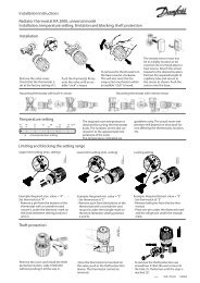
1.3 Installation overview<br />
An overview of the installation is shown in the figure below:<br />
Pos. Description<br />
1 Heat pump Thermia Atec Standard, Atec Plus<br />
2 Heat pump Thermia Atec Total<br />
3 Outdoor unit (Master)<br />
4 Outdoor unit (Slave)<br />
1<br />
Thermia Värmepumpar VMILD102 5<br />
2<br />
4<br />
3
6<br />
Installation Guide <strong>Twin</strong> <strong>Kit</strong><br />
1.4 Positioning of <strong>Twin</strong> <strong>Kit</strong> <strong>com</strong>ponents<br />
1.4.1 Components in control unit<br />
The positions of the <strong>Twin</strong> <strong>Kit</strong> <strong>com</strong>ponents in the control unit are shown in the figure below:<br />
Fig. 1: Components in control unit<br />
Pos. Description<br />
1 Expansion card<br />
2 HUB card<br />
3 Expansion block<br />
4 X2 terminal block<br />
5 Cover for cable duct<br />
4<br />
VMILD102 Thermia Värmepumpar<br />
1<br />
3<br />
5<br />
2
Installation Guide <strong>Twin</strong> <strong>Kit</strong><br />
1.4.2 Components in electrical cabinet<br />
The positions of the <strong>Twin</strong> <strong>Kit</strong> <strong>com</strong>ponents in the electrical cabinet are shown in the figure below:<br />
Fig. 2: Components in the electrical cabinet<br />
Pos. Description<br />
1 HP card<br />
2 EEV card<br />
3 Power terminal block<br />
4 X1 Terminal block<br />
1<br />
4<br />
3<br />
2<br />
Thermia Värmepumpar VMILD102 7
8<br />
Installation Guide <strong>Twin</strong> <strong>Kit</strong><br />
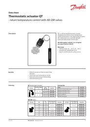
1.4.3 Delivery check<br />
The <strong>Twin</strong> kit accessory is shown in the figure below:<br />
6 7 8 9 10<br />
1 2 3 11 4<br />
Accessories for the <strong>Twin</strong> <strong>Kit</strong> installation are supplied in an enclosed cardboard box. Check that the contents correspond to the following<br />
table:<br />
Pos. Part No. Quantity Description<br />
1 086U9240 1 Expansion card<br />
2 086L0766 1 Cable harness, expansion card<br />
3 086U9977 1 Block, expansion card<br />
4 086U8427 1 RJ-45 <strong>com</strong>munication cable, 1,000 mm<br />
5 086U0086 4 Circuit board support<br />
6 086U9709 1 Supply line sensor 110<br />
7 086U9710 1 Return line sensor 111<br />
8 086U2672 1 System supply line sensor<br />
9 086L0918 1 Installation instructions for expansion card and terminal block<br />
10 086L1334 1 These installation instructions<br />
11 2 Rivets<br />
VMILD102 Thermia Värmepumpar<br />
5
Installation Guide <strong>Twin</strong> <strong>Kit</strong><br />
2 Preparations<br />
Before starting the <strong>Twin</strong>-<strong>Kit</strong> installation, the following steps must be taken:<br />
1. Installation of control unit (1, or 2) and outdoor unit (Master) (3).<br />
2. Installation of additional outdoor unit (Slave) (4).<br />
3. Installation of expansion card and terminal block, with cable harness.<br />
1<br />
Fig. 3: <strong>Twin</strong>-<strong>Kit</strong> installation with control unit and outdoor units<br />
2.1 Installation of heat pump with control unit and outdoor unit (Master)<br />
Carry out the normal installation as outlined in the heat pump Installation guide.<br />
2.2 Installation of additional outdoor unit (Slave)<br />
Position the additional outdoor unit in accordance with the Transport, unpacking and positioning chapter in the Installation guide.<br />
Connect the supply and return lines in accordance with System solutions appendix.<br />
Thermia Värmepumpar VMILD102 9<br />
2<br />
4<br />
3
10<br />
Installation Guide <strong>Twin</strong> <strong>Kit</strong><br />
2.3 Installation of Expansion card and terminal block with cable harness<br />
1 2 3<br />
Install the expansion card and terminal block with cable harness in accordance with the attached Installation of expansion card and terminal<br />
block instructions. See position 1, 2, and 3.<br />
VMILD102 Thermia Värmepumpar
Installation Guide <strong>Twin</strong> <strong>Kit</strong><br />
3 Installation of <strong>Twin</strong> kit<br />
The installation consists of the following procedures:<br />
1. Electrical Installation<br />
2. Commissioning<br />
3. Settings in the control system<br />
3.1 Electrical Installation<br />
Electrical installation is carried out in accordance with the following activities:<br />
1. Control unit<br />
2. Outdoor unit’s electrical cabinet (Slave)<br />
3. RJ-45 <strong>com</strong>munication cable<br />
4. Communication cable between control unit and outdoor units (Master and Slave)<br />
Control unit<br />
See Figure 1 on page 6 for the location of the <strong>com</strong>ponents in the control unit.<br />
Thermia Värmepumpar VMILD102 11
12<br />
Installation Guide <strong>Twin</strong> <strong>Kit</strong><br />
Electrical connections in control unit<br />
Circulation pump<br />
N<br />
1<br />
Only applicable for control units with in-built circulation pump. That is for the Thermia Atec Plus and<br />
Atec Total heat pump models.<br />
1<br />
1<br />
2 3<br />
1. Disconnect the circulation pump from the terminal block by<br />
loosening the contacts from the connections marked 101.1,<br />
N and PE. See position 1.<br />
2. Peel off the cable sheath about 120 mm. See position 1.<br />
3. Reconnect the circulation pump by connecting the wires as<br />
follows:<br />
▪ Wires which were connected to the X2 terminal block,<br />
marked 101.1, are connected to the expansion board,<br />
marked 201.11. See position 2.<br />
▪ Wires which were connected to the X2 terminal block,<br />
marked N, are connected to the X2 terminal block,<br />
marked N, (same connection as before). See position 1.<br />
▪ Wires which were connected to the X2 terminal block,<br />
marked PE, are connected to the expansion board,<br />
marked PE. See position 3.<br />
VMILD102 Thermia Värmepumpar
Installation Guide <strong>Twin</strong> <strong>Kit</strong><br />
0-10V and alarm<br />
N<br />
Only applicable for control units with in-built circulation pump. That is for the Thermia Atec Plus and<br />
Atec Total heat pumps models.<br />
1<br />
1<br />
1<br />
2<br />
3<br />
1. Disconnect the 0-10 V and alarm from the terminal<br />
block by loosening the wires from the<br />
connections marked 116.1, 116.2 and COM.<br />
See position 1.<br />
2. Reconnect the 0-10 V and alarm to the expansion<br />
board by connecting the wires as follows:<br />
▪ Wires which were connected to the X2<br />
terminal block, marked 116.1, are connected<br />
to the expansion board, marked<br />
206.1. See position 2.<br />
▪ Wires which were connected to the X2<br />
terminal block, marked 116.2, are connected<br />
to the expansion board, marked<br />
206.2. See position 3.<br />
▪ Wires which were connected to the X2<br />
terminal block, marked COM, are connected<br />
to the expansion board, marked<br />
COM. See position 1.<br />
Thermia Värmepumpar VMILD102 13
14<br />
Installation Guide <strong>Twin</strong> <strong>Kit</strong><br />
Slave sensor<br />
N<br />
Not applicable for the Thermia Atec Standard heat pump.<br />
2<br />
1 2 3<br />
1<br />
1<br />
1. Disconnect the supply line sensor’s Molex contact on the<br />
HUB card from the connection marked 110. See position 1.<br />
2. For Thermia Atec Total heat pump, the Molex contact<br />
which is connected to the connection, marked 111, must<br />
be disconnected. See position 2.<br />
3. Loosen the cables by cutting away the cable tie so that<br />
the cables can be pulled back. Then run them to the lower<br />
corner of the assembly plate under the expansion board.<br />
See position 1.<br />
4. Cut off the connector house and peel off the wire insulation.<br />
See position 1.<br />
VMILD102 Thermia Värmepumpar
Installation Guide <strong>Twin</strong> <strong>Kit</strong><br />
Master sensor<br />
N<br />
1 2 3<br />
Not applicable for the Thermia Atec Standard heat pump.<br />
4<br />
1<br />
3<br />
5<br />
1<br />
2<br />
5. Connect the supply line sensor wire to the expansion card<br />
connections as follows:<br />
▪ Connect the red wire to the expansion board connection<br />
marked 208.4. See position 3.<br />
▪ Connect the white wire to the expansion board connection<br />
marked COM. See position 2.<br />
6. For the Thermia Atec Total heat pump, the return line sensor<br />
wire must be connected to the expansion board connections<br />
marked 208.5 and COM.<br />
1. Remove the cover on the cable duct located above the<br />
HUB card. See position 5.<br />
2. Take out the supply line cable (with the mounted Molex<br />
connector marked 110,1 and 110,2) from the cable duct.<br />
See position 1.<br />
3. For the Thermia Atec Total heat pumps, take out the return<br />
line cable (with mounted Molex connector marked<br />
111,1 and 111,2) from the cable duct.<br />
Thermia Värmepumpar VMILD102 15
16<br />
Installation Guide <strong>Twin</strong> <strong>Kit</strong><br />
4<br />
3<br />
2<br />
1<br />
4. Connect the supply line cables (with mounted Molex<br />
connectors) to the HUB card connection marked 110.<br />
See position 1.<br />
5. For the Thermia Atec Total heat pumps, the return line<br />
cables (with the mounted Molex connectors) must be<br />
connected to the HUB card connection marked 111. See<br />
position 2.<br />
6. Pick up the enclosed supply line sensor (marked 110)<br />
and the return line sensor (marked 111) from the <strong>Twin</strong><br />
<strong>Kit</strong>.<br />
7. Connect the supplied supply line sensor as follows:<br />
▪ Connect the red wire to the X2 terminal block connection<br />
marked 110. See position 4.<br />
▪ Connect the white wire to the X2 terminal block X2<br />
marked COM. See position 3.<br />
8. Connect the supplied return line sensor as follows:<br />
▪ Connect the red wire to the X2 terminal block connection<br />
marked 111.<br />
▪ Connect the white wire to the X2 terminal block<br />
connection marked COM.<br />
9. Pick up the enclosed system supply line sensor from the<br />
<strong>Twin</strong> <strong>Kit</strong>.<br />
10. Connect the supplied system supply line sensor as follows:<br />
▪ Connect the red wire to the X2 terminal block connection<br />
marked 118.2.<br />
▪ Connect the white wire to the X2 terminal block<br />
connection marked COM.<br />
VMILD102 Thermia Värmepumpar
Installation Guide <strong>Twin</strong> <strong>Kit</strong><br />
Electrical cabinet for the outdoor unit (Slave)<br />
See figure 2 on page 7 for the unit’s position in the outdoor unit’s electrical cabinet.<br />
1<br />
1<br />
1. Remove the jumper from the EEV card. See position 1.<br />
2. Move the dipswitch on the HP card from position 1 to position<br />
2. See position 1.<br />
Thermia Värmepumpar VMILD102 17
18<br />
Installation Guide <strong>Twin</strong> <strong>Kit</strong><br />
RJ-45 <strong>com</strong>munication cable<br />
See Figure 1 on page 6 for the positions in the control unit.<br />
1<br />
3.2 Communication cable between control unit and outdoor units<br />
N<br />
The <strong>com</strong>munication cable is not supplied.<br />
The <strong>com</strong>munication cable is connected as follows:<br />
1. Between the control unit and outdoor unit (Master)<br />
2. Between the outdoor units (Master and Slave)<br />
Communication cable between control unit and outdoor unit (Master)<br />
See figure 1 on page 6 for the positioning in the control unit.<br />
See figure 2 on page7 for the positioning in the outdoor unit’s electrical cabinet.<br />
1<br />
1. Connect the supplied RJ-45 <strong>com</strong>munication cable to the<br />
expansion card output marked 209. See position 1.<br />
2. Connect the other end of the RJ-45 <strong>com</strong>munication cable<br />
to the HUB card’s output marked 123. See position 1.<br />
VMILD102 Thermia Värmepumpar
Installation Guide <strong>Twin</strong> <strong>Kit</strong><br />
1 2<br />
3<br />
2<br />
1<br />
3<br />
1. Connect the <strong>com</strong>munication cable to the terminal block<br />
(control unit) as follows:<br />
▪ Connect a wire to the X2 terminal block connection<br />
marked BUS_A. See position 1.<br />
▪ Connect a conductor to the X2 terminal block connection<br />
marked BUS_B. See position 3.<br />
▪ Connect a conductor to the X2 terminal block connection<br />
marked COM. See position 2.<br />
2. Connect the other end of the <strong>com</strong>munication cable to the<br />
X1 block (outdoor unit’s electrical cabinet) as follows:<br />
▪ Connect a wire to the X1 block connection marked<br />
BUS_A. See position 1.<br />
▪ Connect a wire to the X1 block connection marked<br />
BUS_B. See position 2.<br />
▪ Connect a conductor to the X1 block connection<br />
marked COM. See position 3.<br />
Thermia Värmepumpar VMILD102 19
20<br />
Installation Guide <strong>Twin</strong> <strong>Kit</strong><br />
Communication cable between outdoor units, Master and Slave<br />
See figure 2 on page 7 for the positioning in the outdoor unit’s electrical cabinet.<br />
3.3 Commissioning<br />
Connect the external supply voltage.<br />
3.4 Settings in the control system<br />
The following symbols are used to control the menu selection in the control unit:<br />
Symbol Description<br />
+ ”Arrow button +” on control unit<br />
- ”Arrow button -" on control unit<br />
-> ”Right arrow button” on control unit<br />
Installation Guide <strong>Twin</strong> <strong>Kit</strong><br />
Input the following settings on the control unit:<br />
1 Start-up, Settings for Master<br />
2 Start-up, Settings for Slave<br />
3 Basic settings for heat pump units<br />
4 Settings for selection, Optimum<br />
5 Settings for hot water<br />
6 Settings for cooling<br />
7 Settings for electric auxiliary heater<br />
8 Check, Manual test<br />
9 Operation<br />
Thermia Värmepumpar VMILD102 21
22<br />
Installation Guide <strong>Twin</strong> <strong>Kit</strong><br />
4 Start up<br />
4.1 Settings for Master<br />
1. Press and hold to select INSTALLATION.<br />
4. Press –> to select SYSTEM.<br />
5. Press – to scroll down to MASTER/SLAV.<br />
6. Press –> to select MASTER/SLAV. The selection is selected.<br />
Then press + to activate.<br />
» Result: MASTER/SLAV = ON.<br />
7. Press to select OPTI-<br />
MUM. The selection is selected. Then press + to activate.<br />
» Result: OPTIMUM = ON.<br />
4.2 Settings for Slave<br />
1. Press and hold –> for 5-10 seconds.<br />
» The SERVICE menu is shown.<br />
2. Press – to scroll down to INSTALLATION.<br />
3. Press –> to select INSTALLATION.<br />
4. Press –> to select SYSTEM.<br />
▪ If an adjustable Class A circulation pump is to be used<br />
for the slave unit, go to Step 5.<br />
▪ Otherwise, continue to Step 7.<br />
5. Press – to scroll down to OPTIMUM. Press –> to select OPTI-<br />
MUM. The selection is selected. Then press + to activate.<br />
» Result: OPTIMUM = ON.<br />
6. Press to select<br />
FACTORY SET.<br />
5. Press – to scroll down to RADIATOR or FLOOR. Press –> to<br />
select RADIATOR or FLOOR.<br />
» An asterisk (*) is shown next to the selected option.<br />
9. Press to select HEAT<br />
SOURCE.<br />
11. Press –> to select AIR.<br />
» DIRECT EVAP. is shown.<br />
12. Press and hold –> for approx 20 seconds.<br />
» HEAT PUMP OUTPUT is shown.<br />
13. Press – to select size. Press –> when the correct size is selected.<br />
» An asterisk (*) is shown next to the selected heat pump<br />
output.<br />
14. Press to select HEAT SOURCE.<br />
8. Press –> to select AIR.<br />
» DIRECT EVAP. is shown.<br />
9. Press and hold –> for approx 20 seconds.<br />
» HEAT PUMP OUTPUT is shown.<br />
10. Press – to select size. Press –> when the correct size is selected.<br />
» An asterisk (*) is shown next to the selected heat pump<br />
output.<br />
11. Press
Installation Guide <strong>Twin</strong> <strong>Kit</strong><br />
4.4 Settings for options<br />
Optimum<br />
1. For Master: Press and hold for 5-10 seconds.<br />
▪ Continue to Step 3.<br />
» The SERVICE menu is shown.<br />
Settings for hot water<br />
1. Press and hold to select HOT WATER.<br />
3. Press –> to select START.<br />
4. Press + to set the desired start temperature for hot water.<br />
» The re<strong>com</strong>mended start temperature is 40 °C.<br />
5. Press to select COOL-<br />
ING.<br />
4. Press –> to select COOLING. Press –> again.<br />
» The settings menu opens.<br />
5. Press − to go to AKTIV COOLING. Press –> to select AKTIV<br />
COOLING.<br />
6. Press –> to select INTEGRATED IN HP.<br />
» An asterisk (*) is shown.<br />
Settings for electrical auxiliary heater<br />
1. Press and hold to select<br />
AUX. HEATER.<br />
3. Press –> to select MAX STEP. Press + to set the desired stepped<br />
setting for the electric auxiliary heater. Press to select OPTI-<br />
MUM.<br />
» See the heat pump Installation instructions for the parameter<br />
meanings.<br />
4. Press again to select<br />
HOT WATER. Then press + to activate HOT WATER.<br />
» Result: HOT WATER = ON.<br />
9. Press again to<br />
select the option. Press + to activate the option.<br />
» Result: EXT. AUX. HEATER = ON.<br />
6. Press
24<br />
Installation Guide <strong>Twin</strong> <strong>Kit</strong><br />
4.5 Check<br />
Manual test<br />
1. For Master: Press and hold for approx 5-10 seconds.<br />
▪ Go to Step 3.<br />
» The SERVICE menu is shown.<br />
3. Press – to scroll down to MANUAL TEST. Press –> to select<br />
MANUAL TEST.<br />
4. Press –> to select MANUAL TEST.<br />
5. Press + to set the system to MANUAL TEST.<br />
» Result: MANUAL TEST = 1.<br />
4.6 Operation<br />
1. Press to select OPERAT.<br />
3. Press – to scroll down to AUTO.<br />
4. Press –> to select AUTO.<br />
» An asterisk (*) is shown next to the selected option.<br />
5. Press and to select MANUAL TEST. Press – to end MANUAL<br />
TEST.<br />
» Result: MANUAL TEST = 0.<br />
8. Press
Installation Guide <strong>Twin</strong> <strong>Kit</strong><br />
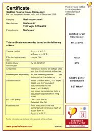
5 Appendix System solution<br />
A<br />
B<br />
10<br />
11<br />
5<br />
5<br />
96<br />
96<br />
103<br />
100<br />
Pos. Description<br />
A Master<br />
B Slave<br />
5 Heat pump unit<br />
10 Supply line<br />
11 Return line<br />
12 Cold water<br />
13 Hot water<br />
18 Hot water tank<br />
30 Circulation pump<br />
36 Circ.pump (system)<br />
40 Control unit<br />
49 Supply line sensor system<br />
50 Outdoor sensor<br />
51 Supply line sensor (hp)<br />
52 Return line sensor<br />
53 Hot water sensor start (hp)<br />
55 Hot water sensor top (hp)<br />
60 Sensor pool<br />
62 Room sensor<br />
60<br />
83<br />
51<br />
36<br />
91<br />
117<br />
101<br />
52<br />
80<br />
50<br />
63<br />
49<br />
62<br />
30<br />
40<br />
104<br />
120<br />
79<br />
83<br />
77<br />
51<br />
36<br />
100<br />
114<br />
91<br />
83<br />
52<br />
80<br />
85<br />
55<br />
53<br />
107 108 109<br />
112<br />
63 Shunt valve (2nd shunt)<br />
77 Reversing valve<br />
79 Reversing valve cooling<br />
80 Shut-off valve<br />
83 Non-return valve<br />
85 Venting valve<br />
87 Safety valve (9 bar)<br />
91 Strainer filter ball<br />
96 Flexible hose<br />
100 Safety valve (3,0 bar)<br />
101 Reversing valve pool<br />
103 Heat exchanger pool<br />
104 Expansion card<br />
107 Shunt valve (shuntgrp 1)<br />
108 Supply line sensor (shuntgrp 1)<br />
109 Circ.pump (shuntgrp 1)<br />
112 Expansion tank<br />
114 Additional heater<br />
117 Additional heater<br />
120 Cooling unit (-s)<br />
Thermia Värmepumpar VMILD102 25<br />
80<br />
18<br />
87<br />
83<br />
80<br />
10<br />
11<br />
10<br />
11<br />
13<br />
12
26<br />
Installation Guide <strong>Twin</strong> <strong>Kit</strong><br />
VMILD102 Thermia Värmepumpar
Installation Guide <strong>Twin</strong> <strong>Kit</strong><br />
Thermia Värmepumpar VMILD102 27
Installation Guide <strong>Twin</strong> <strong>Kit</strong><br />
Thermia Heat Pumps<br />
Box 950<br />
671 29 ARVIKA<br />
Phone +46 570 81300<br />
E-mail: info@thermia.<strong>com</strong><br />
Internet: www.thermia.<strong>com</strong><br />
<strong>Danfoss</strong> can accept no responsibility for possible errors in catalogues, brochures and other printed material. <strong>Danfoss</strong> reserves the right to alter its products without notice. This also applies to products<br />
already on order provided that such alterations can be made without subsequential changes being necessary in specifications already agreed. All trademarks in this material are property of the respective<br />
<strong>com</strong>panies. Thermia Värmepumpar and the Thermia Värmepumpar logotype are trademarks of <strong>Danfoss</strong> A/S. All rights reserved.<br />
VMILD102 Produced by Thermia Värmepumpar © 2013