
Create successful ePaper yourself
Turn your PDF publications into a flip-book with our unique Google optimized e-Paper software.
MAKING MODERN LIVING POSSIBLE<br />
Technical paper<br />
k V: what, why, how, whence?<br />
Herman Boysen, Product Application Manager, <strong>Danfoss</strong> A/S<br />
districtenergy.danfoss.<strong>com</strong>
TECHNICAL PAPER<br />
k v: what, why, how, whence?<br />
What?<br />
The k v - factor for a given valve is<br />
a constant which in a simple way states<br />
the valve capacity. The k v - factor is<br />
determined by the valve manufacturer<br />
by experiments. The k v - factor specifies<br />
the water flow in m 3 through the valve<br />
in one hour at a pressure drop across<br />
the valve of 1 Bar.<br />
Why?<br />
The k v - factor is an exact and easily<br />
applicable value for use when<br />
calculating pressure drops, sizing,<br />
and ordering valves.<br />
How?<br />
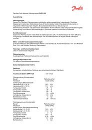
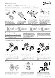
Imagine that you are going to size<br />
a motorised valve for a room heating<br />
system in a District Heating Network<br />
(fig. 1). The calculated flow rate Q<br />
is 1,8 l/sec = 6,5 m 3 /h. And the pressure<br />
drop Δp available for the motorised<br />
valve is 50 kPa = 0,50 bar.<br />
By using the formula<br />
k v<br />
the desired k v value can be calculated.<br />
k<br />
v<br />
=<br />
=<br />
Q<br />
∆p<br />
6,<br />
5<br />
0,<br />
50<br />
m<br />
=<br />
3<br />
/ h<br />
9,<br />
2<br />
m<br />
3<br />
/ h<br />
From the datasheets you will see that<br />
a VM2 or VB2 with the kvs = 10 m 3 /h can<br />
be used.<br />
Whence?<br />
The concept of kv originates from U.S.A.<br />
and was published for the first time in<br />
November 1944. However, kv is not used<br />
in U.S.A. but is replaced by Cv.<br />
C v stands for Valve Flow Coefficient.<br />
In English Cv is today mostly described<br />
as Cv - factor or flow factor Cv. To make<br />
the confusion <strong>com</strong>plete, there is not<br />
one but two Cv - factors, because the<br />
FIGURE 1<br />
Q Flow rate<br />
Author(s)<br />
Herman Boysen,<br />
Product Application Manager, <strong>Danfoss</strong> A/S<br />
<strong>Danfoss</strong> District Energy, Nordborg, Denmark,<br />
+45 7488 4123 · boy@danfoss.<strong>com</strong><br />
American and the English measuring<br />
systems are not quite identical. If you<br />
wish to avoid any misunderstanding,<br />
and you should always try to do so<br />
today where even the smallest piece of<br />
information will find its way to the<br />
remotest places of the world, it is<br />
necessary to state the type of gallon<br />
used, Cv US indicates the water flow in<br />
US gallons through the valve in one<br />
minute at a pressure drop across the<br />
valve of one pound per square inch.<br />
Cv UK indicates the water flow in UK<br />
gallons through the valve in one minute<br />
at a pressure drop across the valve of<br />
one pound per square inch.<br />
ESM-10 ECL ESM-10<br />
FV<br />
AVP<br />
2 <strong>Danfoss</strong> District Energy<br />
AMV-20<br />
∆p<br />
ESM-<br />
kV<br />
ESM
Technical Paper k v: What, Why, How, Whence ?<br />
One US gallon = 3.785 litres and one UK<br />
gallon = 4.546 litres. The other<br />
American and British units are identical.<br />
One pound per square inch is written<br />
1 lb/in2 = = 1 psi. The kv - factor – or the<br />
kv - value as it is also called – is defined<br />
in VDI/VDE Richtlinien No. 2173.<br />
A simplified version of the definition is:<br />
The k v - factor of a valve indicates the<br />
water flow in m 3 /h at a pressure drop<br />
across the valve of 1 kg /cm 2 when the<br />
valve is <strong>com</strong>pletely open. The <strong>com</strong>plete<br />
definition also says that the flow<br />
medium must have a specific gravity of<br />
1000 kg /m 3 and a kinematic viscosity of<br />
10 −6 m 2 /s. Water for heating systems<br />
satisfies these conditions with sufficient<br />
accuracy. This is the reason that the<br />
subsequent summary of formula can be<br />
made simple and clear.<br />
Some Theory<br />
The concept of kv is based on the<br />
hydrodynamic law saying that the<br />
pressure drop (Δp) in a valve, s in any<br />
resistance to flow, is proportional to the<br />
square on the flow volume (Q): Δp ~<br />
proportional to Q 2 . If we take a few<br />
concrete examples, the ratio between<br />
these can be written:<br />
∆p<br />
Q<br />
or<br />
or<br />
Q<br />
1<br />
2<br />
1<br />
∆p<br />
∆p<br />
1<br />
1<br />
2<br />
=<br />
= Q<br />
Q<br />
Since the definition of kv says that the<br />
kv-factor indicates the capacity through<br />
the valve at a pressure drop of Δp = 1<br />
Bar, we can put Q2 = kv and p2 = 1 Bar.<br />
100 kPa = 1 Bar.<br />
Q<br />
1<br />
∆p<br />
=<br />
Q<br />
= Q<br />
2<br />
<strong>Danfoss</strong> District Energy<br />
2<br />
Q<br />
2<br />
2<br />
2<br />
2<br />
1<br />
2<br />
2<br />
∆p<br />
∆p<br />
∆p<br />
∆p<br />
1<br />
2<br />
1<br />
2<br />
then has the form<br />
1<br />
Q1 = k v = k v ∆<br />
Q = k<br />
v<br />
⎛<br />
∆p<br />
= ⎜<br />
⎝<br />
Q<br />
k<br />
∆p<br />
v<br />
∆p<br />
1<br />
The indicies 1 can now be eliminated<br />
and are omitted. Q = k v √∆p is<br />
transchribed once more, and the final<br />
formula for k v emerges.<br />
k v<br />
For practical reasons we are presenting<br />
the formula in three different versions<br />
k v<br />
=<br />
=<br />
Q<br />
∆p<br />
Q<br />
∆p<br />
⎞<br />
⎟<br />
⎠<br />
2<br />
m<br />
m<br />
m<br />
/ h<br />
3<br />
Bar<br />
/ h<br />
By using one of these three formulae,<br />
we can always easily determine one<br />
value when we know the other two.<br />
It is often of importance to be able to<br />
convert from kv into Cv US or Cv UK or vice<br />
versa.<br />
Conversion Factors<br />
1 kv = 1 Cv US × 0.86 and<br />
1 Cv US = 1 kv × 1.17<br />
1 kv = 1 Cv UK × 1.03 and<br />
1 Cv UK = 1 kv × 0.97<br />
3<br />
3<br />
/ h<br />
p<br />
1<br />
3
Technical Paper k v: What, Why, How, Whence ?<br />
More articles<br />
More information<br />
VF.HB.G2.02<br />
[1] Valve charateristics for motorized valves in district heating substations,<br />
by Atli Benonysson and Herman Boysen<br />
[2] Optimum control of heat exchangers, by Atli Benonysson and Herman Boysen<br />
[3] Auto tuning and motor protection as part of the pre-setting<br />
procedure in a heating system, by Herman Boysen<br />
[4] Differential pressure controllers as a tool for optimization of heating systems,<br />
by Herman Boysen<br />
[5] District heating house substations and selection of regulating valves,<br />
by Herman Boysen<br />
[6] Pilot controlled valve without auxiliary energy for heating and cooling systems,<br />
by Martin Hochmuth<br />
[7] Pressure oscillation in district heating installation, by Bjarne Stræde<br />
[8] Dynamic simulation of DH House Stations, by Jan Eric Thorsen<br />
Find more information on <strong>Danfoss</strong> District Energy products and applications<br />
on our homepage: www.districtenergy.danfoss.<strong>com</strong><br />
Produced by <strong>Danfoss</strong> A/S, DH-SM/PL © 09/2011