
Create successful ePaper yourself
Turn your PDF publications into a flip-book with our unique Google optimized e-Paper software.
1<br />
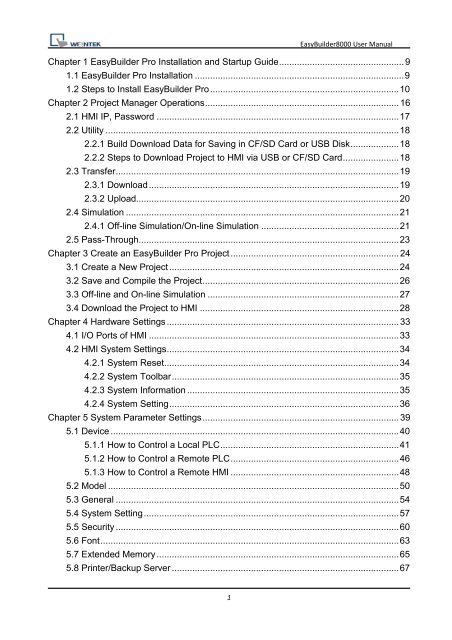
EasyBuilder8000 <strong>User</strong> Manual<br />
Chapter 1 EasyBuilder Pro Installation and Startup <strong>Guide</strong> ................................................. 9<br />
1.1 EasyBuilder Pro Installation .................................................................................. 9<br />
1.2 Steps to Install EasyBuilder Pro .......................................................................... 10<br />
Chapter 2 Project Manager Operations ............................................................................ 16<br />
2.1 HMI IP, Password ............................................................................................... 17<br />
2.2 Utility ................................................................................................................... 18<br />
2.2.1 Build Download Data for Saving in CF/SD Card or USB Disk ................... 18<br />
2.2.2 Steps to Download Project to HMI via USB or CF/SD Card ...................... 18<br />
2.3 Transfer ............................................................................................................... 19<br />
2.3.1 Download .................................................................................................. 19<br />
2.3.2 Upload....................................................................................................... 20<br />
2.4 Simulation ........................................................................................................... 21<br />
2.4.1 Off-line Simulation/On-line Simulation ...................................................... 21<br />
2.5 Pass-Through...................................................................................................... 23<br />
Chapter 3 Create an EasyBuilder Pro Project .................................................................. 24<br />
3.1 Create a New Project .......................................................................................... 24<br />
3.2 Save and Compile the Project ............................................................................. 26<br />
3.3 Off-line and On-line Simulation ........................................................................... 27<br />
3.4 Download the Project to HMI .............................................................................. 28<br />
Chapter 4 Hardware Settings ........................................................................................... 33<br />
4.1 I/O Ports of HMI .................................................................................................. 33<br />
4.2 HMI System Settings ........................................................................................... 34<br />
4.2.1 System Reset ............................................................................................ 34<br />
4.2.2 System Toolbar ......................................................................................... 35<br />
4.2.3 System Information ................................................................................... 35<br />
4.2.4 System Setting .......................................................................................... 36<br />
Chapter 5 System Parameter Settings ............................................................................. 39<br />
5.1 Device ................................................................................................................. 40<br />
5.1.1 How to Control a Local PLC ...................................................................... 41<br />
5.1.2 How to Control a Remote PLC .................................................................. 46<br />
5.1.3 How to Control a Remote HMI .................................................................. 48<br />
5.2 Model .................................................................................................................. 50<br />
5.3 General ............................................................................................................... 54<br />
5.4 System Setting .................................................................................................... 57<br />
5.5 Security ............................................................................................................... 60<br />
5.6 Font ..................................................................................................................... 63<br />
5.7 Extended Memory ............................................................................................... 65<br />
5.8 Printer/Backup Server ......................................................................................... 67
2<br />
EasyBuilder8000 <strong>User</strong> Manual<br />
Chapter 6 Window Operations ......................................................................................... 69<br />
6.1 Window Types..................................................................................................... 69<br />
6.1.1 Base Window ............................................................................................ 69<br />
6.1.2 Fast Selection Window.............................................................................. 70<br />
6.1.3 Common Window ...................................................................................... 71<br />
6.1.4 System Message Window ......................................................................... 72<br />
6.2 Create, Set, and Delete a Window ...................................................................... 74<br />
6.2.1 Creating and Setting a Window ................................................................. 74<br />
6.2.2 Open, Close and Delete a Window ........................................................... 77<br />
Chapter 7 Event Log ........................................................................................................ 78<br />
7.1 Event Log Management ...................................................................................... 78<br />
7.1.1 Excel Editing ............................................................................................. 79<br />
7.2 Create a New Event Log ..................................................................................... 80<br />
7.2.1 Alarm (Event) Log General Settings ......................................................... 80<br />
7.2.2 Alarm (Event) Log Message Settings ........................................................ 82<br />
7.3 Event Log Relevant Registers ............................................................................. 84<br />
Chapter 8 Data Sampling ................................................................................................. 85<br />
8.1 Data Sampling Management ............................................................................... 85<br />
8.2 Create a New Data Sampling .............................................................................. 86<br />
8.3 System Registers Relevant to Data Sampling..................................................... 90<br />
Chapter 9 Object General Properties ............................................................................... 91<br />
9.1 Selecting PLC ..................................................................................................... 91<br />
9.1.1 Setting the Reading and Writing Address ................................................. 91<br />
9.2 Using Shape Library and Picture Library ............................................................. 94<br />
9.2.1 Settings of Shape Library .......................................................................... 94<br />
9.2.2 Settings of Picture Library ......................................................................... 98<br />
9.3 Setting Text Content ......................................................................................... 101<br />
9.4 Adjusting Profile Size ........................................................................................ 106<br />
9.5 Variables of Station Number ............................................................................. 107<br />
9.6 Broadcast Station Number ................................................................................ 109<br />
Chapter 10 Security ....................................................................................................... 110<br />
10.1 <strong>User</strong> Password and Operable Object Classes ................................................ 110<br />
10.2 Object Security Settings .................................................................................. 111<br />
10.3 Setting Example .............................................................................................. 112<br />
Chapter 11 Index Register ............................................................................................. 115<br />
11.1 Introduction ..................................................................................................... 115<br />
11.2 Examples of Index Register ............................................................................ 116<br />
Chapter 12 Keyboard Design and Usage ....................................................................... 119
3<br />
EasyBuilder8000 <strong>User</strong> Manual<br />
12.1 Steps to Design a Pop-up Keyboard ............................................................... 120<br />
12.2 Steps to Design a Keyboard with Direct Window ............................................ 122<br />
12.3 Steps to Design a Fixed Keyboard on Screen ................................................ 123<br />
12.4 Steps to Design a UNICODE Keyboard .......................................................... 124<br />
Chapter 13 Objects ........................................................................................................ 125<br />
13.1 Bit Lamp .......................................................................................................... 125<br />
13.2 Word Lamp...................................................................................................... 128<br />
13.3 Set Bit ............................................................................................................. 133<br />
13.4 Set Word ......................................................................................................... 137<br />
13.5 Function Key ................................................................................................... 145<br />
13.6 Toggle Switch.................................................................................................. 152<br />
13.7 Multi-State Switch ........................................................................................... 155<br />
13.8 Slider ............................................................................................................... 159<br />
13.9 Numeric Input and Numeric Display ................................................................ 163<br />
13.10 ASCII Input and ASCII Display ...................................................................... 175<br />
13.11 Indirect Window ............................................................................................. 180<br />
13.12 Direct Window ............................................................................................... 185<br />
13.13 Moving Shape ............................................................................................... 189<br />
13.14 Animation ...................................................................................................... 195<br />
13.15 Bar Graph...................................................................................................... 200<br />
13.16 Meter Display ................................................................................................ 208<br />
13.17 Trend Display ................................................................................................ 216<br />
13.18 History Data Display ...................................................................................... 227<br />
13.19 Data Block Display ........................................................................................ 235<br />
13.20 XY Plot .......................................................................................................... 248<br />
13.21 Alarm Bar and Alarm Display ........................................................................ 262<br />
13.22 Event Display ................................................................................................ 266<br />
13.23 Data Transfer (Trigger-based)....................................................................... 275<br />
13.24 Backup .......................................................................................................... 278<br />
13.25 Media Player ................................................................................................. 285<br />
13.26 Data Transfer (Time-based) .......................................................................... 297<br />
13.27 PLC Control................................................................................................... 301<br />
13.28 Schedule ....................................................................................................... 308<br />
13.29 Option List ..................................................................................................... 329<br />
13.30 Timer ............................................................................................................. 336<br />
13.31 Video In ......................................................................................................... 340<br />
13.32 System Message ........................................................................................... 344<br />
Chapter 14 Shape Library and Picture Library ............................................................... 346
4<br />
EasyBuilder8000 <strong>User</strong> Manual<br />
14.1 Creating Shape Library ................................................................................... 346<br />
14.2 Creating Picture Library .................................................................................. 353<br />
Chapter 15 Label Library and Multi-Language Usage .................................................... 360<br />
15.1 Introduction ..................................................................................................... 360<br />
15.2 Building Label Library ...................................................................................... 361<br />
15.3 Setting Label Font ........................................................................................... 362<br />
15.4 Using Label Library ......................................................................................... 363<br />
15.5 Settings of Multi-Language (System Register LW-9134) ................................ 364<br />
Chapter 16 Address Tag Library ..................................................................................... 366<br />
16.1 Creating Address Tag Library .......................................................................... 366<br />
16.2 Using Address Tag Library .............................................................................. 368<br />
Chapter 17 Transferring Recipe Data ............................................................................ 369<br />
17.1 Updating Recipe Data with Ethernet or USB cable ......................................... 370<br />
17.2 Updating Recipe Data with CF/SD Card or USB Disk ..................................... 371<br />
17.3 Transferring Recipe Data ................................................................................ 372<br />
17.4 Saving Recipe Data Automatically .................................................................. 372<br />
Chapter 18 Macro Reference ......................................................................................... 373<br />
18.1 Instructions to the Macro Editor....................................................................... 373<br />
18.2 Macro Construction ......................................................................................... 385<br />
18.3 Syntax ............................................................................................................. 386<br />
18.3.1 Constants and Variables ....................................................................... 386<br />
18.3.2 Operators .............................................................................................. 389<br />
18.4 Statement ........................................................................................................ 393<br />
18.4.1 Definition Statement .............................................................................. 393<br />
18.4.2 Assignment Statement .......................................................................... 393<br />
18.4.3 Logical Statements ............................................................................... 394<br />
18.4.4 Selective Statements ............................................................................ 395<br />
18.4.5 Reiterative Statements .......................................................................... 397<br />
18.5 Function Blocks ............................................................................................... 400<br />
18.6 Build-In Function Block ................................................................................... 403<br />
18.6.1 Mathematical Functions ........................................................................ 403<br />
18.6.2 Data Transformation ............................................................................. 409<br />
18.6.3 Data Manipulation ................................................................................. 415<br />
18.6.4 Bit Transformation ................................................................................. 418<br />
18.6.5 Communication ..................................................................................... 420<br />
18.6.6 String Operation Functions ................................................................... 436<br />
18.6.7 Miscellaneous ....................................................................................... 462<br />
18.7 How to Create and Execute a Macro .............................................................. 469
5<br />
EasyBuilder8000 <strong>User</strong> Manual<br />
18.7.1 How to Create a Macro ......................................................................... 469<br />
18.7.2 Execute a Macro ................................................................................... 474<br />
18.8 <strong>User</strong> Defined Macro Function.......................................................................... 475<br />
18.8.1 Import Function Library File .................................................................. 476<br />
18.8.2 How to Use Macro Function Library ...................................................... 478<br />
18.8.3 Function Library Management Interface ............................................... 480<br />
18.9 Some Notes about Using the Macro ............................................................... 487<br />
18.10 Use the Free Protocol to Control a Device .................................................... 488<br />
18.11 Compiler Error Message ............................................................................... 495<br />
18.12 Sample Macro Code ..................................................................................... 502<br />
18.13 Macro TRACE Function ................................................................................ 507<br />
18.14 The Usage of String Operation Functions ..................................................... 516<br />
18.15 Macro Password Protection .......................................................................... 528<br />
Chapter 19 Set HMI as a MODBUS Server .................................................................... 530<br />
19.1 Setting HMI as MODBUS Device .................................................................... 530<br />
19.1.1 Creating a MODBUS Server ................................................................. 530<br />
19.1.2 Read from / Write to MODBUS Server .................................................. 533<br />
19.2 Changing the Station Number of a MODBUS Server in Runtime .................... 536<br />
19.3 About MODBUS Address Type ....................................................................... 537<br />
Chapter 20 How to Connect a Barcode Device .............................................................. 538<br />
20.1 How to Connect a Barcode Device ................................................................. 538<br />
Chapter 21 Ethernet Communication and Multi-HMI Connection ................................... 542<br />
21.1 HMI to HMI Communication ............................................................................ 543<br />
21.2 PC to HMI Communication .............................................................................. 544<br />
21.3 Operate the PLC Connected with Other HMI .................................................. 545<br />
Chapter 22 System Reserved Words / Bits .................................................................... 546<br />
22.1 The Address Ranges of Local HMI Memory ................................................... 547<br />
22.1.1 Bits ........................................................................................................ 547<br />
22.1.2 Words.................................................................................................... 548<br />
22.2 HMI Time ........................................................................................................ 549<br />
22.3 <strong>User</strong> Name and Password .............................................................................. 550<br />
22.4 Data Sampling ................................................................................................. 551<br />
22.5 Event Log ........................................................................................................ 553<br />
22.6 HMI Hardware Operation ................................................................................ 555<br />
22.7 Local HMI Network Information ....................................................................... 556<br />
22.8 Recipe and Extended Memory ........................................................................ 557<br />
22.9 Storage Space Management........................................................................... 559<br />
22.10 Touch Position .............................................................................................. 560
6<br />
EasyBuilder8000 <strong>User</strong> Manual<br />
22.11 Station Number Variables ............................................................................. 561<br />
22.12 Index Register ............................................................................................... 562<br />
22.13 MTP File Information ..................................................................................... 563<br />
22.14 MODBUS Server Communication ................................................................. 564<br />
22.15 Communication Parameters Settings ............................................................ 566<br />
22.16 Communication Status with PLC (COM) ....................................................... 569<br />
22.17 Communication Status with PLC (Ethernet) .................................................. 571<br />
22.18 Communication Status with PLC (USB) ........................................................ 575<br />
22.19 Communication Status with Remote HMI ...................................................... 576<br />
22.20 Communication Status with Remote PLC ..................................................... 582<br />
22.21 Communication Error Messages & No. of Pending Cmd. ............................. 585<br />
22.22 Miscellaneous Functions ............................................................................... 586<br />
22.23 Remote Print/Backup Server ......................................................................... 588<br />
22.24 EasyAccess................................................................................................... 589<br />
22.25 Pass-Through Settings .................................................................................. 590<br />
22.26 Disable PLC No Response Dialog Box ......................................................... 591<br />
22.27 HMI and Project Key ..................................................................................... 592<br />
22.28 Fast Selection Window Control ..................................................................... 593<br />
22.29 Input Object Function .................................................................................... 594<br />
22.30 Local/Remote Operation Restrictions ............................................................ 595<br />
Chapter 23 HMI Supported Printers ............................................................................... 596<br />
23.1 The Supported Printer Types .......................................................................... 596<br />
23.2 How to Add a New Printer and Start Printing .................................................. 600<br />
23.2.1 Add Printer Type ................................................................................... 600<br />
23.2.2 Start Printing ......................................................................................... 601<br />
Chapter 24 Recipe Editor ............................................................................................... 602<br />
24.1 Introduction ..................................................................................................... 602<br />
24.2 Recipe Editor Setting ...................................................................................... 602<br />
Chapter 25 EasyConverter ............................................................................................. 605<br />
25.1 How to Export to Excel .................................................................................... 605<br />
25.2 How to Use Scaling Function .......................................................................... 607<br />
25.3 How to Use Multi-File Conversion ................................................................... 609<br />
Chapter 26 EasyPrinter .................................................................................................. 610<br />
26.1 Using EasyPrinter as a Printer Server ............................................................. 611<br />
26.1.1 Setup Procedure in EasyPrinter ............................................................ 611<br />
26.1.2 Setup Procedure in EasyBuilder8000 ................................................... 612<br />
26.2 Using EasyPrinter as a Backup Server ........................................................... 615<br />
26.2.1 Setup Procedure in EasyPrinter ............................................................ 615
7<br />
EasyBuilder8000 <strong>User</strong> Manual<br />
26.2.2 Setup Procedure in EasyBuilder8000 ................................................... 616<br />
26.3 EasyPrinter Operation <strong>Guide</strong> .......................................................................... 619<br />
26.3.1 Appearance ........................................................................................... 619<br />
26.3.2 Operation <strong>Guide</strong> .................................................................................... 620<br />
26.4 Convert Batch File ........................................................................................... 625<br />
26.4.1 The Default Convert Batch File ............................................................. 625<br />
26.4.2 Specialized Criteria ............................................................................... 626<br />
26.4.3 The Format of a Convert Batch File ...................................................... 627<br />
26.4.4 The Order of Examining Criteria ........................................................... 628<br />
Chapter 27 EasySimulator ............................................................................................. 629<br />
27.1 Prepare Needed Files ..................................................................................... 629<br />
27.2 Modify the Content of “xob_pos.def” ............................................................... 630<br />
Chapter 28 Multi-HMI Intercommunication (Master-Slave Mode) ................................... 631<br />
28.1 How to Create a Project of Master HMI ........................................................... 632<br />
28.2 How to Create a Project of Slave HMI ............................................................. 633<br />
28.3 How to Connect with MT500 Project of Slave HMI .......................................... 636<br />
Chapter 29 Pass-Through Function ............................................................................... 639<br />
29.1 Ethernet Mode ................................................................................................. 640<br />
29.1.1 How to Change the Virtual <strong>Serial</strong> Port .................................................. 641<br />
29.1.2 How to Use Ethernet Mode ................................................................... 644<br />
29.2 COM Port Mode .............................................................................................. 646<br />
29.2.1 Settings of COM Port Mode .................................................................. 646<br />
29.2.2 HMI Work Mode .................................................................................... 649<br />
29.3 Using System Reserved Addresses to Enable Pass-Through Function .......... 652<br />
Chapter 30 Project Protection ........................................................................................ 653<br />
30.1 XOB Password ................................................................................................ 654<br />
30.2 Decompilation is Prohibited ............................................................................. 655<br />
30.3 Disable HMI Upload Function [LB-9033] ......................................................... 656<br />
30.4 Project Key ...................................................................................................... 657<br />
30.5 Project Password (MTP file) ............................................................................ 658<br />
Chapter 31 Memory Map Communication ...................................................................... 659<br />
Chapter 32 FTP Server Application ................................................................................ 669<br />
32.1 Login FTP Server ............................................................................................ 669<br />
32.2 Backup History Data and Update Recipe Data ............................................... 671<br />
Chapter 33 EasyDiagnoser ............................................................................................ 673<br />
33.1 Overview and Configuration ............................................................................ 673<br />
33.2 EasyDiagnoser Settings .................................................................................. 676<br />
33.3 Error Code ...................................................................................................... 683
8<br />
EasyBuilder8000 <strong>User</strong> Manual<br />
33.4 Save As ........................................................................................................... 684<br />
33.5 Window Adjustment ........................................................................................ 685<br />
Chapter 34 AB EtherNet/IP Free Tag Names ................................................................ 686<br />
34.1 Import <strong>User</strong>-Defined AB Tag to <strong>EB8000</strong> ......................................................... 687<br />
34.2 Adding New Data Type ................................................................................... 689<br />
34.3 Paste ............................................................................................................... 692<br />
34.4 Miscellaneous ................................................................................................. 695<br />
34.5 Module-Defined ............................................................................................... 696<br />
Chapter 35 Easy Watch ................................................................................................. 700<br />
35.1 Overview ......................................................................................................... 700<br />
35.1.1What’s Easy Watch? .............................................................................. 700<br />
35.1.2 Why Design Easy Watch? ..................................................................... 700<br />
35.2 Basic Functions ............................................................................................... 701<br />
35.2.1 Basic Functions ..................................................................................... 701<br />
35.2.2 Quick Selection Tools ........................................................................... 703<br />
35.3 Monitor Settings .............................................................................................. 704<br />
35.3.1 Add Monitor ........................................................................................... 704<br />
35.3.2 Monitor Settings .................................................................................... 704<br />
35.3.3 Add New Device ................................................................................... 705<br />
35.4 Macro Settings ................................................................................................ 708<br />
35.4.1 Add Macro ............................................................................................. 708<br />
35.4.2 Macro Settings ...................................................................................... 708<br />
35.4.3 Add New Macros to the List .................................................................. 709<br />
35.5 HMI Manager .................................................................................................. 710<br />
35.5.1 HMI Settings ......................................................................................... 710<br />
35.5.2 HMI Manager ........................................................................................ 710<br />
35.5.3 Add New Device ................................................................................... 710<br />
35.6 Object List ....................................................................................................... 712<br />
35.6.1 Page Settings ........................................................................................ 712<br />
35.6.2 Columns of Object List .......................................................................... 712
9<br />
EasyBuilder8000 <strong>User</strong> Manual<br />
Chapter 1 EasyBuilder Pro Installation and Startup <strong>Guide</strong><br />
1.1 EasyBuilder Pro Installation<br />
Software:<br />
Download EasyBuilder Pro configuration software from EasyBuilder Pro CD or visiting<br />
Weintek Labs, Inc.’s website at http://www.weintek.com to obtain all software versions<br />
available (including Simplified Chinese, Traditional Chinese, English, Italian, Korean,<br />
Spanish, Russian, and French version) and latest upgraded files.<br />
Hardware Requirements (Recommended):<br />
CPU: INTEL Pentium II or higher<br />
Memory: 256MB or higher<br />
Hard Disk: 2.5GB or higher (Disc space available at least 500MB)<br />
CD-ROM: 4X or higher<br />
Display: 256 color SVGA with 1024 x 768 resolution or greater<br />
Keyboard and Mouse<br />
Ethernet: for project downloading/uploading<br />
USB Port 2.0: for project downloading/uploading<br />
RS-232 COM: At least one available RS-232 serial port required for on-line simulation<br />
Printer<br />
Operating System:<br />
Windows XP / Windows Vista / Windows 7.
1.2 Steps to Install EasyBuilder Pro<br />
1. Installing EasyBuilder Pro:<br />
10<br />
EasyBuilder8000 <strong>User</strong> Manual<br />
Put the EasyBuilder Pro Installation CD into the CD drive. The computer will run the<br />
program automatically and bring up a screen showing an area to click to begin the<br />
EasyBuilder Pro installation. If the auto-run sequence does not start, browse the CD, and<br />
find the root directory of [Autorun.exe] manually. The installation screen is shown<br />
below.<br />
`<br />
2. Click [Install], users will see the window below, select the language and click [Next]<br />
following the installation instructions.<br />
EnglishSpanishFrenchItalian<br />
Simplified ChineseTraditional
11<br />
EasyBuilder8000 <strong>User</strong> Manual<br />
3. <strong>User</strong>s will be asked if they would like to remove the old versions of EasyBuilder 8000.<br />
Please tick those should be removed and click [Next] to continue.
12<br />
EasyBuilder8000 <strong>User</strong> Manual<br />
4. Designate a new folder for EasyBuilder Pro installation or choose the folder<br />
recommended and then click [Next].<br />
5. <strong>User</strong>s will be enquired to select a start menu folder to save the program’s shortcuts.<br />
Click [Browse] to designate a folder or use the folder recommended then click [Next].
13<br />
EasyBuilder8000 <strong>User</strong> Manual<br />
6. <strong>User</strong>s will be enquired if there are any additional tasks to be done. For example: [Create<br />
a desktop icon]. Tick it if needed then click [Next] to continue.<br />
7. At this moment all the settings are done. Please check if they are all correct. If any<br />
changes need to be made, click [Back] or click [Install] to start installing.
8. Installation processing.<br />
9. Click [Finish] to complete the installation.<br />
14<br />
EasyBuilder8000 <strong>User</strong> Manual
15<br />
EasyBuilder8000 <strong>User</strong> Manual<br />
10. Start EasyBuilder Pro project from menu [Start] / [All Programs] / [EBpro].<br />
The description of each item in EasyBuilder Pro menu:<br />
Installed file Description<br />
Support AB TAG mechanism and improve the flexibility of an object<br />
in read/write.<br />
EasyBuilder Pro editing software.<br />
Conversion tool for Data Sampling and Event Log.<br />
Tool for analyzing and detecting connection between HMI and PLC.<br />
Tool for saving hardcopy or backup data is individually<br />
downloadable even without full application.<br />
Upon completion of project programming, you can execute Online<br />
Simulation on PC by directly connect with PLC or Offline Simulation<br />
on PC without connecting PLC.<br />
EasyBuilder Pro project management.<br />
Tool for setting format of Recipe data. <strong>User</strong>s can open Recipe data<br />
or data in External Memory here.<br />
Notes for EasyBuilder Pro version and latest information.<br />
Review the register range of device types for each PLC supported.<br />
■ HMI i Series support downloading/uploading project via USB cable.<br />
After installing EasyBuilder Pro, Please go to [Computer Management] /<br />
[Device Manager] to check if USB driver is also installed, if not, please refer to installation<br />
steps to manually install.
Chapter 2 Project Manager Operations<br />
16<br />
Project Manager Operations<br />
0BAfter installing EasyBuilder Pro software, double click on [Project Manager] shortcut.<br />
1BThe Project Manager is a software shell for launching several utilities. Some functions are<br />
duplicated in the EasyBuilder Pro project editing program. Project Manager can operate as<br />
a stand-alone program.<br />
76B2BClick the buttons on the dialog box for detail.<br />
74B72B70B68B71B69B73B75B<br />
When operating HMI,<br />
designate Password<br />
first.<br />
Launch project<br />
editor.<br />
Conversion tool for<br />
Data Sampling/<br />
Event Log.<br />
Remote printer<br />
/backup server.<br />
Memory format<br />
conversion and data<br />
editing.<br />
Allow PC<br />
applications to<br />
connect PLC via<br />
HMI.<br />
After rebooting,<br />
everything returns to<br />
the startup condition.<br />
Connect via USB<br />
cable or Ethernet to<br />
check the HMI history<br />
files information.<br />
Review the register<br />
range of device types<br />
of supported PLC.<br />
Tool for analyzing<br />
connection between<br />
HMI and PLC.<br />
Build data for<br />
downloading to HMI<br />
via CF/SD/USB.
57B2.1 HMI IP, Password<br />
84B3B[Settings]<br />
17<br />
Project Manager Operations<br />
4BWhen operating HMI via Ethernet or USB cable,<br />
users need to designate the password for HMI<br />
to protect against unauthorized access.<br />
5B[Reset / Download] functions share a set of password while [Upload] function uses<br />
another set.<br />
6BBe sure to record any password change, otherwise, while resetting<br />
password to default, the project and data on HMI will be completely erased.<br />
82B7B[Reboot HMI]<br />
8BThere are certain situations that the HMI<br />
should reboot, for example, when updating<br />
the files in it. <strong>User</strong>s don’t need to cut power<br />
while rebooting. After rebooting, everything<br />
returns to the conditions of startup. Set the<br />
correct IP address when operating HMI via<br />
Ethernet.<br />
9B[Data/Event Log File Information]<br />
10BAfter setting, connect with HMI to check<br />
the number of history files in HMI
58B2.2 Utility<br />
62B2.2.1 Build Download Data for Saving in CF/SD Card or USB Disk<br />
77B<br />
63B2.2.2 Steps to Download Project to HMI via USB or CF/SD Card<br />
18<br />
Project Manager Operations<br />
11BTake downloading data in the folder named “123” (K:\123) in USB stick for example.<br />
1. 12BInsert USB (project included.) to HMI.<br />
2. 13BOn<br />
[Download / Upload] dialog box select [Download].<br />
3. 14BInput Download Password.<br />
4. 15BOn<br />
[Download Settings] dialog box, check [Download project files] and [Download<br />
history files].<br />
5. 16BPress [OK].<br />
6. 17BOn<br />
1. Insert CF/SD/USB to PC.<br />
2. Assign data storing path.<br />
3. Assign files to download.<br />
4. Build data.<br />
The source files will be<br />
saved in the inserted device<br />
for users to download to<br />
HMI. This function is to build<br />
the required data.<br />
[Pick a Directory] dialog box, select directory: usbdisk/device-0/123.<br />
7. 18BPress [OK].<br />
19BProject will be automatically updated.<br />
20BEven if users only download historical files, it is still necessary to reboot<br />
HMI manually to update files.
59B2.3 Transfer<br />
64B2.3.1 Download<br />
21BDownload source files to HMI through Ethernet or USB cable.<br />
78B 22BCheck to update<br />
HMI kernel programs. Must<br />
do when first time download<br />
data to HMI.<br />
23BClick to assign<br />
desired downloading path.<br />
24BNecessary when first time<br />
download data to X series<br />
HMI using EasyBuilder Pro.<br />
25B(i series only)<br />
26BDownload assigned BMP to<br />
HMI. On HMI, it will be<br />
shown after rebooting then<br />
load in project. <strong>User</strong>s may<br />
use company logos.<br />
27BAutomatically reboot after<br />
download.<br />
28B[Reset recipe] / [Reset event log] / [Reset data log]<br />
29BErase specified files on HMI before download.<br />
19<br />
Project Manager Operations
65B2.3.2 Upload<br />
30BUpload files from HMI to PC via Ethernet or USB cable.<br />
31B<strong>User</strong>s have to assign the desired path for file storage before uploading.<br />
85B<br />
20<br />
Project Manager Operations<br />
Click<br />
32BThe file will be uploaded to PC in *.XOB file format. For editing this file<br />
using EasyBuilder Pro, please decompile it into *. MTP file first.<br />
To assign desired<br />
uploading path.
60B2.4 Simulation<br />
66B2.4.1 Off-line Simulation/On-line Simulation<br />
40BOff-line simulation-Simulate project operation on PC.<br />
79B<br />
41BOn-line simulation-Simulate project operation on PC.<br />
80B<br />
Simulate<br />
operations<br />
without<br />
connecting PLC.<br />
Connect<br />
PC-PLC & set<br />
correct<br />
parameters to<br />
operate.<br />
21<br />
Project Manager Operations<br />
OK without HMI<br />
&PLC and save<br />
more time<br />
No need to<br />
download project<br />
to HMI.<br />
33BWhen On-line simulating on PC, if the control target is a local PLC (i.e. the<br />
PLC directly connected to PC), there is 10 minutes simulation limit.
22<br />
Project Manager Operations<br />
Before executing On-line/Off-line Simulation features, please select the source *.XOB file.<br />
34BWhen executing on-line/off-line simulation, right click to use two functions:<br />
35B[Run EasyDiagnoser]<br />
36BTo monitor current<br />
communication status.<br />
37B[Screenshot]<br />
38BCapture and save current<br />
screen image as picture<br />
file in the screenshot<br />
folder under installation<br />
directory.
61B2.5 Pass-Throug81Bh<br />
23<br />
Project Manager Operations<br />
42BThis function allows the PC application to connect PLC via HMI. In this case, the HMI acts<br />
as a converter.<br />
43BPass-through provides two modes: [Ethernet] and [COM port].<br />
44BWhen using [Ethernet], please install the virtual serial port driver first.<br />
39BFor detail, please refer to “Chapter 29 Pass Through Function”.
24<br />
Create an EasyBuilder Pro Project<br />
Chapter 3 Create an EasyBuilder Pro Project<br />
Click on the icons to see illustration.<br />
Create a<br />
Project<br />
In this Chapter, we will take Mitsubishi PLC as an example.<br />
3.1 Create a New Project<br />
1. Click on icon New.<br />
2. Select [Model].<br />
3. Tick [Use template].<br />
4. Click [OK].<br />
Save &<br />
Compile<br />
8. Device “MISUBISHI FX0n/FX2” is<br />
added to the [Device List].<br />
On-line<br />
Off-line<br />
Simulation<br />
Download<br />
to HMI<br />
5. Click [New].<br />
6. Set correct parameters.<br />
7. Click [OK].
Now let’s add a new object.<br />
1. Click on the object icon Toggle Switch Object.<br />
2. Set correct parameters.<br />
3. Place the object wherever<br />
you like on window.<br />
4. A project with one object is<br />
now created.<br />
25<br />
Create an EasyBuilder Pro Project
3.2 Save and Compile the Project<br />
On EasyBuilder Pro Tool Bar:<br />
<strong>User</strong>s are allowed<br />
to select the<br />
languages needed<br />
for the project by<br />
clicking<br />
[Language 1 to 8].<br />
A successfully compiled file will get this dialog box.<br />
26<br />
Create an EasyBuilder Pro Project<br />
1. Click to [Save] *.MTP file. 2. Click to [Compile] to *.XOB file<br />
for downloading to HMI, this also<br />
checks if the project can run<br />
correctly.
3.3 Off-line and On-line Simulation<br />
Off-line simulation - Simulate project operation on PC<br />
On-line simulation - Simulate project operation on PC<br />
Off-line<br />
On-line<br />
Click after correctly<br />
connecting the device.<br />
Simulate<br />
operations<br />
without<br />
connecting PLC.<br />
Connect<br />
PC-PLC & set<br />
correct<br />
parameters.<br />
27<br />
Create an EasyBuilder Pro Project<br />
OK without HMI<br />
&PLC and save<br />
more time.<br />
OK without HMI<br />
and save more<br />
time.<br />
When On-line simulating on PC, if the control target is a local PLC (i.e. the<br />
PLC directly connected to PC), there is 10 minutes simulation limit.
3.4 Download the Project to HMI<br />
Way 1 [Ethernet] / HMI IP<br />
Before [Download], be sure to check if all the<br />
settings are correct.<br />
Input [Password] &<br />
Specify [HMI IP].<br />
Update HMI kernel<br />
programs. Must do this<br />
when first time<br />
download files to HMI.<br />
Download the font<br />
used in project.<br />
The selected files will<br />
be erased before<br />
downloading.<br />
HMI will reboot after downloading.<br />
28<br />
Create an EasyBuilder Pro Project<br />
If this is checked, system will download project to HMI according to last settings.<br />
Please see illustration below.
The way to enable this<br />
function:<br />
1. Click [Function<br />
Properties].<br />
2. Tick [Automatic save and compile when download and simulate].<br />
3. [Save] project.<br />
4. Click [Download].<br />
5. On dialog box, tick<br />
[Automatically using current<br />
settings to download after<br />
compiling].<br />
6. Click [Download].<br />
7. After finish setting, next time<br />
when click [Download],<br />
EasyBuilder Pro will<br />
automatically compile and<br />
download project to the latest target HMI.<br />
29<br />
Create an EasyBuilder Pro Project
Way 2 [Ethernet] / HMI Name<br />
1. On HMI set HMI name first.<br />
2. On PC, select the set HMI name and start downloading.<br />
30<br />
Create an EasyBuilder Pro Project<br />
Input the HMI name to search the<br />
designated HMI.<br />
Click to search the HMIs share<br />
the same network.
Way 3 [USB Cable]<br />
31<br />
Create an EasyBuilder Pro Project<br />
Select USB cable to<br />
download project to<br />
HMI. The way of setting<br />
is same as Way 1<br />
mentioned above. USB<br />
cable only works for i<br />
Series HMI.<br />
■ Before downloading via USB cable, please make sure the USB driver is<br />
correctly installed. Go to [Computer Management] / [Device Manager] to<br />
check if USB driver is installed, if not, please refer to installation steps to manually<br />
install.
Way 4 [USB Disk / SD Card]<br />
[OK] to start downloading.<br />
32<br />
Create an EasyBuilder Pro Project<br />
1. In Project Manager<br />
click [Build<br />
The download data storing structure:<br />
2. Insert external devices to HMI.<br />
Download Data for<br />
CF / SD / USB Disk]<br />
to build the data to be<br />
downloaded first.<br />
Generally divided into<br />
2 directories, if set as<br />
the way shown:<br />
3. Select [Download] and input correct password.<br />
4. Password confirmed, show directories in external<br />
device.(pccard: SD/CF Cardusbdisk: USB Disk)<br />
5. Select a directory for storing project then click<br />
Please select the top layer directory of the target file when downloading.<br />
For the structure above, select download, not mt8000 or history.<br />
Project storage<br />
Directory created when<br />
downloading history data
4.1 I/O Ports of HMI<br />
Chapter 4 Hardware Settings<br />
The I/O ports are different form one HMI type to another.<br />
Download/ Upload project via SD<br />
Card, including Recipe transfer,<br />
Event Log, Data Log…etc and to<br />
backup or record History data.<br />
Connects PLC or other peripheral<br />
devices.<br />
RS-232 / RS-485 2W/4W<br />
RS-422 = RS-485 4W<br />
Connects Ethernet devices, such as<br />
PLC, laptop, for exchanging data<br />
via Network.<br />
Supports USB devices, such as<br />
mouse, keyboard, USB disk, printer<br />
Download/ Upload project including<br />
Recipe transfer, Event Log, Data<br />
Log…etc.<br />
33<br />
Hardware Settings<br />
In addition, Weintek provides [MT8-COM1 Multi-Connector cable] and [MT8-COM3<br />
Multi-Connector cable] to expand one COM port to multiple independent COM ports so that<br />
the convenience and efficiency of operation can be improved.
4.2 HMI System Settings<br />
34<br />
Hardware Settings<br />
For the first time operating HMI, users have to complete the HMI system settings. After this,<br />
users can develop their own operation interface through EasyBuilder Pro editing software.<br />
4.2.1 System Reset<br />
Each HMI is equipped with a set of reset<br />
button and DIP switch. When using DIP<br />
switch to change modes, the<br />
corresponding functions will be triggered.<br />
If system password is lost or forgotten,<br />
please set DIP Switch 1 to “ON” and the<br />
rest remain “OFF”, then reboot HMI. HMI<br />
will switch to touch screen calibration<br />
mode.<br />
1. A “+” sign appears on the screen, touch the center of the sign, after all 5 signs are<br />
touched, “+” disappears and the touch screen parameter will be stored in HMI system.<br />
2. After calibration, confirm to restore the system password to the default, select [YES].<br />
3. Confirm to restore to default password again by typing [yes] and clicking [OK]. The<br />
project files and history records stored in HMI will all be removed. (The default password<br />
is 111111. However, other passwords, including download/upload passwords have to be<br />
reset.)<br />
The above shows the steps to restore factory settings of T and i Series HMI. For X<br />
Series, users will need a connected USB keyboard, and press any key (or space key)<br />
right when the first image displayed as HMI power ON to enter the menu. Select "Factory<br />
Mode", the window mentioned will pop up when system displays project. In case users<br />
may miss the very first image shown, to press space key continuously since HMI power<br />
ON will ensure entering the system setting window.<br />
SW1 SW2 SW3 SW4 Mode<br />
ON OFF OFF OFF Touch screen calibration mode (X Series excluded)<br />
OFF ON OFF OFF Hide system toolbar (T Series excluded)<br />
OFF OFF ON OFF Boot loader mode (X Series excluded)<br />
OFF OFF OFF ON Enable front panel power switch (X Series only)<br />
OFF OFF OFF OFF Normal
35<br />
Hardware Settings<br />
4.2.2 System Toolbar<br />
After rebooting HMI, users can set the system with System Toolbar at the bottom of the<br />
screen. Normally, this bar is hidden automatically. Only by touching the target at the<br />
bottom-right corner of the screen will the System Toolbar pops up.<br />
How to hide HMI System Setting Toolbar<br />
EasyBuilder Pro supports the function of using system tag [LB-9020] to enable/disable<br />
system setting bar, or set the [DIP Switch 2] to ON/OFF for activating this function.<br />
When [LB-9020] is set ON, the bar is displayed, and set OFF to hide the system setting bar.<br />
When [DIP Switch 2] is set ON, the system setting bar is disabled, and when set OFF; the<br />
system setting bar is able to control. <strong>User</strong>s have to restart HMI to enable/disable this<br />
function.<br />
Note: [LB-9020] is available for all HMI series. [DIP Switch 2] is available for i and X Series.<br />
Screen Calibration shortcut, X Series only, for<br />
other series, turn SW1 to ON. When X Series<br />
touch screen drifting problem occurs, please<br />
connect an USB mouse to select this mode.<br />
4.2.3 System Information<br />
Text Keyboard Number Keyboard<br />
Network: Display network information & HMI IP. Version: Display HMI system version.
4.2.4 System Setting<br />
Set or modify system parameters.<br />
Confirm password for security.<br />
■ Network<br />
Download project to HMI via Ethernet.<br />
Confirm IP address of target HMI.<br />
[Assign IP by local DHCP] or<br />
[Manually input IP information(<br />
■ Time/Date Setting HMI local time/date.<br />
36<br />
Hardware Settings<br />
■ Security<br />
Password protection, default 111111.<br />
[Password for entering system]<br />
[Password for uploading project]<br />
[Password for downloading project]<br />
[Password for uploading history data]<br />
Password confirmation window:<br />
■ History<br />
Clear history data on HMI.<br />
[Recipe] / [Eventlog] / [Datalog]
■ Miscellaneous<br />
Rolling button for adjusting LCD brightness.<br />
■ Firmware setting<br />
Upgrade firmware / enable portrait mode.<br />
(i series only)<br />
■ HMI name<br />
Set HMI name to download/upload project.<br />
37<br />
Hardware Settings<br />
■ VNC server<br />
Remote HMI monitoring and controlling.<br />
1. Enable HMI VNC server, set password.<br />
2. Install Java IE or VNC Viewer on PC.<br />
3-1 Input remote HMI IP in IE, example:<br />
http://192.168.1.28<br />
3-2 In VNC Viewer input remote HMI IP and<br />
password.
automatically.<br />
38<br />
Hardware Settings<br />
■One HMI allows only one user to log in VNC server at one time. When<br />
leaving VNC server unused for one hour, HMI system will log out
Chapter 5 System Parameter Settings<br />
39<br />
System Parameters Settings<br />
Enter <strong>EB8000</strong>, select menu [Edit] / [System Parameters…] and the [System Parameter<br />
Settings] dialog appears:<br />
System Parameter Settings are divided into eight parts: [Device], [Model], [General],<br />
[System Setting], [Security], [Font], [Extended Memory], and [Printer/Backup<br />
Server].<br />
These will be introduced respectively in this chapter.
1B5.1 Device<br />
40<br />
System Parameters Settings<br />
Parameters in [Device] tab determine all of the attributes of each device controlled by the<br />
HMI they are connected with. The device can be a PLC, a remote HMI, or a PC.<br />
After opening a new *.mtp file in <strong>EB8000</strong>, a default device: “Local HMI” is shown in the<br />
[Device List]. This “Local HMI” is used to identify current HMI, which means, every *.mtp<br />
file must at least contains one “Local HMI” in [Device List].<br />
Select [Settings] under the device list, A dialogue [Device Properties] will be shown as<br />
below. From this we know that the attribute of “Local HMI” is a “HMI” and the location is<br />
“Local”.<br />
Steps to add a new device:
5.1.1 How to Control a Local PLC<br />
41<br />
System Parameters Settings<br />
The so-called “local PLC” means a PLC which is connected to the local HMI directly. To<br />
control a local PLC, users need to add this type of device first. Click [New…] under the<br />
Device list and the [Device Properties] dialog appears. Please correctly fill in all of the<br />
properties required.<br />
Take a local PLC MITSUBISHI FX0n/FX2 as an example:<br />
Setting Description<br />
Name The name of the device set by user.<br />
HMI or PLC To confirm whether this connected device is a HMI or PLC. It’s [PLC]<br />
in this example.
42<br />
System Parameters Settings<br />
Location [Local] or [Remote]. Showing whether this device is connected to<br />
Local HMI or being remote controlled. Select [Local] in this case.<br />
PLC type Type of PLC. Select MITSUBISHI FX0n/FX2 in this case.<br />
PLC I/F Five PLC interfaces are available: [RS-232], [RS-485 2W], [RS-485<br />
4W], [Ethernet], and [USB].<br />
If the interface is [RS-232], [RS-485 2W], or [RS-485 4W], click<br />
[Settings…] and then [Com Port Settings] dialog appears. <strong>User</strong>s<br />
need to correctly set the COM port communication parameters.<br />
[Timeout]<br />
If the communication between PLC and HMI is disconnected over the<br />
set time limit in [Timeout] parameter, a pop out window No. 5 will be<br />
shown in HMI as an alert saying “PLC No Response”.<br />
[Turn around delay]<br />
While sending the next command to PLC, HMI will delay it obeying<br />
the set time interval in [Turn around delay] parameter. This may<br />
influence the efficiency of the communication between HMI and PLC.<br />
If no specific request to be made, “0” is to be set.<br />
If the PLC used is in SIEMENS S7-200 Series, this parameter needs<br />
to be set to “5” and [Parameter 1] “30”.<br />
If the interface is [Ethernet], click [Settings…] and then [IP Address
PLC default<br />
station no.<br />
Default station<br />
no. use station<br />
no. variable<br />
43<br />
System Parameters Settings<br />
Settings] dialogue appears. <strong>User</strong>s need to correctly set IP address<br />
and Port no. of the PLC.<br />
If the interface is [USB], no further settings need to be done. Please<br />
check if all the settings in [Device Properties] are correct.<br />
PLC should be set with a read address alone with a station no. for<br />
HMI to locate and communicate with it. If this address does not<br />
include a station no. <strong>EB8000</strong> will use this [PLC default station no.]<br />
as the station no. of PLC.<br />
In addition, station no. can be set in the read address of PLC directly.<br />
Take address 1#20 as an example.<br />
“1” means PLC station no, and has to be named from 0 to 255.<br />
“20” means PLC address, the “#” sign is used to separate station no.<br />
and address.<br />
When setting PLC properties, station no. variables can be selected<br />
and used as [PLC default station no.]. LW10000~LW10015 can be<br />
used to set station no. variables.<br />
When using this function, if the station no. is not specified for PLC
Use broadcast<br />
command<br />
Interval of<br />
block pack<br />
(words)<br />
44<br />
System Parameters Settings<br />
address, it will be decided by the station no. variable of default station<br />
no. In this example var3 is set for default station no. The following<br />
demonstrates how the PLC address station no. is set.<br />
a. The station number of PLC is “5”.<br />
b. The PLC station no. is decided by var7 (LW-10007)<br />
c. PLC address is set to “111”, since PLC station no. is not specified,<br />
and the default station no. is using var3, the PLC station no. is<br />
decided by var3 (LW-10003).<br />
This is for setting the station no. of broadcast command. Command<br />
for the users of this set station no. will be seen as broadcast<br />
command. For example, if the broadcast station number is set as<br />
255, HMI with an address such as 255#200, will send this command<br />
to all the PLC connected to it, but will ignore the replies of PLC after<br />
receiving this command. (This only works on Modbus).<br />
If the interval between read addresses of different commands is less<br />
than this value, these commands can be combined to one. But<br />
combining function is disabled if this value is “0”.<br />
For example, the interval value is set as “5” and users would like to<br />
read out 1 word from LW3 and 2 words from LW6 respectively.<br />
(Means to read from LW6 to LW7). Since the interval of addresses<br />
between LW3 and LW6 is less than 5, these two commands can be<br />
combined to one. The contents of combination therefore become 5<br />
consecutive words from LW3 (read from LW3~LW7).<br />
Note: Maximum command combination data size must be less than<br />
[Max. read-command size].<br />
Max. The Max. data size to be read out from device at one time. Unit: word
ead-command<br />
size (words)<br />
Max.<br />
write-command<br />
size (words)<br />
45<br />
System Parameters Settings<br />
The Max. data size to be written to device at one time. Unit: word.<br />
After all settings are completed, a new device named “Local PLC 1” is added to the<br />
[Device list].
5.1.2 How to Control a Remote PLC<br />
46<br />
System Parameters Settings<br />
The so -called “remote PLC” means a PLC connected to a remote HMI. To control a<br />
remote PLC, users need to add this type of device. Click [New…] under [Device list] and<br />
the [Device Properties] dialog appears. <strong>User</strong>s need to set all the required properties<br />
correctly.<br />
Here take a remote PLC, SIEMENS S7/200, as an example:<br />
Setting Description
HMI or PLC This is to confirm whether this device is a HMI or PLC.<br />
It is [PLC] in this case.<br />
47<br />
System Parameters Settings<br />
Location <strong>User</strong>s can select [Local] or [Remote]. Select [Remote] in this case<br />
and set the IP address of the remote HMI which is connected to<br />
SIEMENS S7/200 PLC. Click [Settings…] of [Location] to set this IP<br />
address.<br />
PLC Type Type of PLC. Select SIEMENS S7/200 in this case.<br />
PLC I/F This setting defines which interface the remote PLC uses. If the<br />
PLC default<br />
station no.<br />
remote PLC uses a COM port, interface used should be selected from<br />
[RS-232], [RS-485 2W], and [RS485 4W].<br />
This setting defines which default station no. is used by remote PLC.<br />
COM This setting defines which COM port the remote PLC uses to connect<br />
with remote HMI. The settings should be correct.<br />
After all settings are completed, a new device named “Remote PLC” is added to the<br />
[Device list].
11B5.1.3 How to Control a Remote HMI<br />
48<br />
System Parameters Settings<br />
The so-called “remote HMI” means through network, this HMI is controlled by a local HMI<br />
or a PC running on-line simulation. To control a remote HMI, users need to add this type of<br />
device. Click [New…] under [Device list] and the [Device Properties] dialog appears.<br />
<strong>User</strong>s need to set all the required properties correctly.<br />
Setting Description<br />
HMI or PLC This is to confirm whether this device is a HMI or PLC.<br />
It is [HMI] in this case.<br />
Location <strong>User</strong>s can select [Local] or [Remote]. Select [Remote] in this case<br />
and set the [IP address] and [Port no.] of the remote HMI. Click<br />
[Settings…] of [Location] to set these, the dialogue is shown below.<br />
The [Port no.] of remote HMI can be seen in [Model] in [System<br />
parameters] once the* .mtp file of remote HMI is opened. The port<br />
no. of remote HMI and local HMI must be the same.
49<br />
System Parameters Settings<br />
After all settings are completed, a new device named “Remote HMI” is added to the<br />
[Device list].
2B5.2 Model<br />
50<br />
System Parameters Settings<br />
Parameters in [Model] tab determine the HMI model, [Timer] and [Printer] settings.<br />
Setting Description<br />
HMI model Select current HMI model as shown below.<br />
When changing HMI model and press [OK], users will be inquired if
HMI station<br />
no.<br />
they would like to [Resize pop-up windows or objects].<br />
51<br />
System Parameters Settings<br />
Set the [HMI station no.] used by current HMI. If no specific request is<br />
to be made, just use the default number.<br />
Port no. Set the [Port no.] used by current HMI. It is used as port no. of<br />
MODBUS server. If no specific request is to be made, just use the<br />
default number.<br />
Timer [Clock source]<br />
To set up the signal for timer object. The time information of timer is<br />
used by [Data Sampling], [Event Log] ….etc. which are objects that<br />
need the time records.<br />
a. [HMI RTC] means the time signal comes from internal clock of the<br />
HMI.<br />
b. [External device] means the time signal comes from external<br />
device. To correctly set source address of time signal is necessary.<br />
Take the illustration below as an example: It indicates the source of<br />
time signal is from “TV” of the “Local PLC”. The source address “TV”<br />
starts from address 0 contains 6 consecutive words and each of them<br />
contains the following information:<br />
TV 0 → Second (the limited range: 0~59)<br />
TV 1 → Minute (the limited range: 0~59)<br />
TV 2 → Hour (the limited range: 0~23)<br />
TV 3 → Day (the limited range: 1~31)<br />
TV 4 → Month (the limited range: 1~12)<br />
TV 5 → Year (the limit range: 1970~2037)
Printer [Type]<br />
Storage<br />
space<br />
52<br />
System Parameters Settings<br />
Display printers supported. For HP PCL Series, it has to be connected<br />
through USB interface while other printers through COM port. For more<br />
information, please refer to “Chapter 23 Printer Types supported by<br />
MT8000”.<br />
Using [COM] port to connect printer, users should set accurate<br />
parameters. When the type of printer is [SP-M, D, E, F], the [pixels of<br />
width] has to be set accurately, i.e. the set pixel(s) can not exceed<br />
printer’s default setting. Otherwise this printing won’t succeed.<br />
1. Storage space available for the project and history data is 12MB. By<br />
adjusting the space of these two parts, users can reach their
management<br />
( For T series<br />
only)<br />
53<br />
System Parameters Settings<br />
memory requirements, for example, using smaller sized project to<br />
get bigger memory space for historical data. It works contrariwise.<br />
2. Minimum Project size is 6MB; Maximum Project size is 10 MB<br />
(default is 8MB). Minimum Historical data size is 2MB; Maximum<br />
Historical data size is 6 MB (default is 4MB).<br />
3. For adjusting storage space, users should erase history data saved<br />
in HMI before downloading project file.
3B5.3 General<br />
54<br />
System Parameters Settings<br />
Parameters in [General] tab determine all properties related to screen display.<br />
Setting Description<br />
Fast<br />
selection<br />
button<br />
Setting all the attributes for fast selection button that is designated as<br />
window number 3.<br />
a. [Attribute]
Screen<br />
saver<br />
55<br />
System Parameters Settings<br />
Enable or disable fast selection window. Select [Enable] and click<br />
[Settings…] to set the attributes, including color and text.<br />
b. [Position]<br />
Select the position on the screen of HMI where this button appears. If<br />
[Left] is chosen, the button will show up on screen bottom-left; if [Right]<br />
is chosen, the button will show up on screen bottom-right.<br />
a. [Back light saver]<br />
If the screen is left untouched and reaches the time limit set here, back<br />
light will be off. The setting unit is minute. Back light will be on again once<br />
the screen is touched. If [none] is set, the back light will always be on<br />
while using.<br />
b. [Screen saver]<br />
If the screen is left untouched and reaches the time limit set here. The<br />
current screen will automatically switch to a window assigned in [Saver<br />
window no.].The setting unit is minute. If [none] is set, this function is<br />
disabled.<br />
c. [Saver window no.]<br />
To assign a window for screen saver.<br />
Option a. [Startup window no.]<br />
Designate the window shown when start up HMI.<br />
b. [Common window]<br />
The objects in the common window (window 4) will be shown in each<br />
base window. This selection determines the layers these objects are<br />
placed above or below the objects in the base window.<br />
c. [Keyboard caret color]
56<br />
System Parameters Settings<br />
Set the color of caret that appears when inputting in [Numeric Input] and<br />
[Word Input] objects.<br />
d. [Object layout]<br />
If [Control] mode is selected, when operating HMI, [Animation] and<br />
[Moving Shape] objects will be displayed above other kinds of objects<br />
neglecting the sequence that the objects are created. If [Nature] mode is<br />
selected, the display will follow the sequence that the objects are<br />
created, first created be displayed first.<br />
e. [RW_A enabled]<br />
Enable or disable recipe data RW_A. Enable this, the objects can then<br />
control the content of RW_A .The size of RW_A is 64K.<br />
Event [Extra no. of events]<br />
The default number of the event in the system is 1000. If users would like<br />
to add more records, the setting value can be modified up to 10000.<br />
Keyboard <strong>User</strong>s can select to use different types of keyboards for [Numeric Input]<br />
Project<br />
protection (i<br />
series only)<br />
and [Word Input]. Up to 32 keyboards can be added. If users want to<br />
design their own keyboard, a window should be designated for creating<br />
it. Press [add] after creating, and add the window to the list. For more<br />
information, please see “Chapter 12 Key Pad Design and Usage” where<br />
also shows how to fix this keyboard in screen instead of adding it to the<br />
list.<br />
<strong>User</strong>’s project can be restrained and executed on specific HMI (only for i<br />
series HMI). Please refer to “Chapter 30 Project protection” for more<br />
information.
4B5.4 System Setting<br />
57<br />
System Parameters Settings<br />
Parameters in [System Setting] tab are for setting up some miscellaneous functions of<br />
EasyBuilder.<br />
Some functions are duplicated from system tag, such as [Disable buzzer (LB-9019)], [Hide<br />
system setting bar (LB-9020)], [Hide mouse cursor (LB-9018)], [Disable upload function<br />
(LB-9033)], and [Prohibit remote HMI connecting this machine (LB-9044)]. It means that
58<br />
System Parameters Settings<br />
user can also operate these functions via system tag. To select a system tag, users can<br />
tick [system tag] of the [address] while adding new object. To check all the system tags,<br />
users can visit [Library] in <strong>EB8000</strong>, select [Tag] then [System].<br />
[Startup language after redownloading the project]<br />
Set the language to use when start up HMI after redownloading the project.<br />
[Execute init. Macro when power on]<br />
Designate the macro to be executed when HMI power on.<br />
[Auto logout]<br />
If HMI is left unused for longer than the time set here, HMI will logout automatically.<br />
[Use a disconnection icon on relative objects when PLC communication fails]<br />
When using this function and fail to communicate with PLC, this icon will be shown in the<br />
lower right corner of the object as shown:<br />
The disconnection icon<br />
When using this function and fail to communicate with PLC, this icon will be shown in the<br />
lower right corner of the object as shown:<br />
[VNC Server]<br />
Set the login password for VNC server.
[LW protection], [RW protection]<br />
59<br />
System Parameters Settings<br />
If users check [Disable LW/RW remote-write] and set the protect range in [LW/RW<br />
range], values of this protected range can’t be adjusted via remote HMI.<br />
[Easy Access server]<br />
Through this technology, users can easily access to any MT8000i/X connected to the<br />
internet and operate them on PC just like holding touch screen in hand.<br />
Unlike most server used in HMI, Easy Access don’t need to transmit updated graphic<br />
image but real time data only. This makes transmission really quick and efficient.<br />
For further information, please refer to “EasyAccess”.
5B5.5 Security<br />
60<br />
System Parameters Settings<br />
Parameters in [Security] tab determine the classes accessible for each user to adjust the<br />
objects, and users’ password. The security classes of objects are classified from [A~F],<br />
and [none] for not ticking any class. Up to twelve passwords can be set. Only numeral<br />
setting is acceptable for password and the range is 0~999999999.<br />
According to the security setting, <strong>EB8000</strong> will control the classes accessible for each user<br />
to adjust the objects once they input their passwords.<br />
In <strong>EB8000</strong>, while constructing a project, the security classes of objects are classified from<br />
[A~F], and [None] and can be set as shown below.<br />
If [None] is set, every user can access to adjust this object.
61<br />
System Parameters Settings<br />
For example, when the security class of <strong>User</strong>1 is set as below, only objects with class A, C,<br />
E and “none” can the user adjust. For more information, please see “Chapter 10 Security<br />
of Objects”.<br />
[Project password (MTP file)]<br />
<strong>User</strong>s can set password to protect the MTP file in [System parameter] / [Security tab].<br />
<strong>User</strong>s have to input the password set here when they want to edit the MTP file.<br />
(MTP password range: 1~4294967295)<br />
Tick [Enable] then click [Setting], and the window is as shown below.<br />
Before editing project, a pop-up window will ask password for access the project.
62<br />
System Parameters Settings<br />
MTP files are protected by additional encryption, please follow the steps below:<br />
a. <strong>EB8000</strong> V440 or later can open old version <strong>EB8000</strong> projects using the password<br />
originally set in old version <strong>EB8000</strong>.<br />
b. The old version <strong>EB8000</strong> can’t open the projects that are built in <strong>EB8000</strong> V440 or later<br />
which are protected by password, if necessary, please disable (don’t tick [Enable]) the<br />
password first.
5.6 Font<br />
63<br />
System Parameters Settings<br />
Parameters in [Font] tab determine the font of non-ASCII which is used in <strong>EB8000</strong>.<br />
[Fonts for non- strings]<br />
Fonts for non-ASCII strings are listed above. When users use non-ASCII character set or<br />
double byte character set ( including simplified or traditional Chinese character, Japanese,<br />
or Korean) which is not listed in [Fonts for non-ASCII strings] table, <strong>EB8000</strong> will select a<br />
font from the list to substitute for it automatically.<br />
<strong>User</strong>s can also test which non-ASCII strings of Windows can be used in <strong>EB8000</strong> and add<br />
them to [Fonts for non-ASCII strings] table.<br />
[Line spacing]<br />
Decide the interval between lines in the text.
64<br />
System Parameters Settings
7B5.7 Extended Memory<br />
65<br />
System Parameters Settings<br />
Parameters in [Extended Memory] tab determine the path of the extended memory.<br />
Extended Memory is numbered from EM0 to EM9. Method to use extended memory is<br />
similar to that of other device type (i.e. LW or RW address). <strong>User</strong>s can simply select from<br />
[Device type] list while adding a new object. Size of each extended memory is up to 2G<br />
word.
66<br />
System Parameters Settings<br />
Data in extended memory is stored in [SD card], [USB1], or [USB2] in a form of a file. The<br />
files in extended memory [EM0] ~ [EM9] are entitled as em0.emi~em9.emi. <strong>User</strong>s can use<br />
RecipeEditor.exe to open the file and edit the data in the extended memory.<br />
Data in extended memory will not be erased when power is cut, which means next time<br />
when user start HMI again, data in extended memory remains just the same before power<br />
off. This is similar to Recipe data (EW, RW_A). What is different is that users can select<br />
where they want to save the data (SD card, USB1 or USB2)<br />
To read data in extended memory from a removed device, the content of data will be<br />
viewed as “0”; if users would like to write data to a removed device, the "PLC no response"<br />
message will appear in HMI.<br />
<strong>EB8000</strong> supports "hot swapping" function for SD card and USB devices. <strong>User</strong>s can insert<br />
or remove the device for extended memory without cutting the power. With this function,<br />
users can update or take data in extended memory.
8B5.8 Printer/Backup Server<br />
67<br />
System Parameters Settings<br />
Parameters in [Printer/Backup Server] tab are for setting up MT remote printer.<br />
Setting Description<br />
Output settings [Orientation]<br />
Communication<br />
settings<br />
Set how will words or pictures be printed out, [horizontal] or<br />
[vertical].<br />
[Printer size]<br />
Set to print out in original size or to fit the set printer margins.<br />
[Margin]<br />
Set the top, bottom, right and left margin width.<br />
[IP address]<br />
Assign the IP address of a remote printer via network.
[Port], [<strong>User</strong> name], [Password]<br />
Assign the access information.<br />
Port can be set from 1 to 65535.<br />
68<br />
System Parameters Settings<br />
Maximum length of user name or password is 12 characters.<br />
Please refer “Chapter 26 Easy Printer” for more information.
Chapter 6 Window Operations<br />
A window is a basic element in a project. With a window, all kinds of<br />
69<br />
Window Operations<br />
information like objects, pictures, and text can be shown on HMI screen.<br />
Generally, there’s more than one window in a project, many windows will be<br />
constructed in one project. 1997 windows numbered from 3~1999 in<br />
EasyBuilder Pro can be built and edited. For how many windows can be used<br />
in one project, it depends on the storage size for windows of HMI. For<br />
example, the storage size of i series HMI for windows is 16MB, then the size of<br />
windows or screens constructed cannot exceed 16MB. Under this limit users<br />
can make most use of it to create as many windows as possible.<br />
6.1 Window Types<br />
There are 4 types of windows, each with different functions and usages:<br />
(1) Base Window (2) Fast Selection Window (3) Common Window<br />
(4) System Message Window<br />
6.1.1 Base Window<br />
The most frequently used<br />
window, used as:<br />
a. main screen<br />
b. background for other<br />
windows<br />
c. keyboard window<br />
d. pop-up window for [function<br />
key] object.<br />
e. pop-up window for [direct<br />
window] and [indirect<br />
window] objects.<br />
f. screen saver<br />
The start up screen shown on<br />
the right is a Base Window.<br />
■ Base window should be in the same size as the HMI screen.<br />
Therefore, the resolution of base window and HMI should be<br />
identical.
6.1.2 Fast Selection Window<br />
70<br />
Window Operations<br />
Window no. 3 is defined as the Fast Selection Window. This window can<br />
coexist with base window. Generally speaking, it is used to place the<br />
frequently-used operation buttons as shown below:<br />
The [Shortcut] button is a fast selection button used to show / hide fast<br />
selection window.<br />
Fast Selection<br />
Button setting<br />
dialog: [System<br />
Parameter Settings<br />
/ General]<br />
Or use system<br />
registers to control:<br />
[LB-9013] FS window control [hide(ON)/show(OFF)]<br />
[LB-9014] FS button control [hide(ON)/show(OFF)]<br />
[LB-9015] FS window/button control [hide(ON)/show(OFF)]
6.1.3 Common Window<br />
71<br />
Window Operations<br />
Window no. 4 is the default Common Window. Objects on this window will be<br />
displayed on other base windows, but it does not include popup windows.<br />
Therefore, objects on different windows, whether shared or same, will be<br />
placed on common window, for example, the product logo, or a common<br />
button.<br />
When system is in<br />
operation, select<br />
[Function Key] /<br />
[Change common<br />
window] to change the<br />
source of common<br />
window. For example,<br />
change the common<br />
window from window 4<br />
to window 20.<br />
In [Option]/[Function<br />
Properties] select<br />
whether or not to<br />
[Display Common<br />
Window objects on<br />
Base Windows] when<br />
editing project. This can<br />
avoid overlapping<br />
objects on base<br />
window with objects on<br />
common window.
6.1.4 System Message Window<br />
Windows No. 5,6,7,8 are the default System Message Windows:<br />
[Window No. 5: PLC Response]<br />
When the communication between PLC<br />
and HMI is disconnected, this message<br />
window will pop up automatically right on<br />
the base window opened previously.<br />
72<br />
Window Operations<br />
■“PLC no response” window can be set not to pop-up using<br />
system reserved registers. Please refer to “Chapter 22 System<br />
Reserved Words & Bits”.<br />
[Window No. 6: HMI Connection]<br />
When failing to connect HMI with remote<br />
HMI, this message window will pop up<br />
automatically.<br />
[Window No. 7: Password Restriction]<br />
If user attempts to control<br />
an object without<br />
authorization, this window<br />
may pop up as a warning<br />
or not depending on how<br />
this object is set originally.<br />
[Window No.8: Storage Space Insufficient]<br />
When HMI built-in memory, USB disk or SD<br />
card run out of storage space, this message<br />
window will pop up automatically. (When system<br />
detects that memory space left is under 4MB)
73<br />
Window Operations<br />
<strong>User</strong>s can use system address tags to view the free memory space in HMI,<br />
USB disk, or SD card device.<br />
[LW-9072] HMI current free space (K bytes)<br />
[LW-9074] SD/CF current free space (K bytes)<br />
[LW-9076] USB 1 current free space (K bytes)<br />
[LW-9078] USB 2 current free space (K bytes)<br />
For checking which device is insufficient in space while the insufficiency<br />
occurs, the following system address tags can be used.<br />
[LB-9035] HMI free space insufficiency alarm (when ON)<br />
[LB-9036] SD/CF card free space insufficiency alarm (when ON)<br />
[LB-9037] USB 1 free space insufficiency alarm (when ON)<br />
[LB-9038] USB 2 free space insufficiency alarm (when ON)<br />
The text shown on windows no. 5~8 can be adjusted by users to fit what is<br />
needed, making the message easier to be understood by the operators.<br />
20B■A screen<br />
and Indirect Window.<br />
can display 16 pop-up windows simultaneously in<br />
maximum including System Message Window, Direct Window<br />
■A window can only be displayed once simultaneously. That is, users cannot<br />
use 2 Direct (Indirect) windows to open the same window on one base<br />
window at the same time.<br />
■ Windows 3~9 are for system use only while windows 10~1999 are for users<br />
to define.
6.2 Create, Set, and Delete a Window<br />
74<br />
Window Operations<br />
Go to EasyBuilder Pro / [View] / [Window Tree] to check the built windows.<br />
[Object List] displays window number and defined window names. The<br />
currently opened and edited window will contain a (*) mark, press the (+)<br />
beside the window number to see the objects, object ID, addresses and<br />
descriptions this window contains.<br />
[Window Preview] displays windows in small pictures.<br />
6.2.1 Creating and Setting a Window<br />
■ Way 1<br />
On window tree right click on a window<br />
number then select [New].
[Name] The name<br />
will appear on the<br />
title bar and also in<br />
window tree.<br />
[Window no.]<br />
3 ~ 199<br />
Set base window<br />
size identically to<br />
HMI resolution.<br />
[Underlay<br />
window]<br />
Refer to the<br />
description below.<br />
[Popup window]<br />
Base window can<br />
also be used as<br />
pop-up window.<br />
Use [X] and [Y] to<br />
set the coordinates<br />
indicate where on<br />
the screen will this<br />
base window pop<br />
up. The origin of<br />
the coordinates is<br />
the upper-left<br />
corner of the<br />
screen.<br />
[Underlay window]<br />
75<br />
Window Operations<br />
One object can be placed on different windows (but not all windows). Underlay<br />
Window can be seen as an extra Common Window. The objects are placed on<br />
the Base Window where they are built. Up to three Underlay Windows can be<br />
defined by users.<br />
Underlay Window is a base window which can be displayed simultaneously<br />
with the base window which calls it up. Up to three base windows can be<br />
specified as underlay windows for each base window, from [Bottom] to [Top].<br />
The objects (but not the backgrounds) on underlay windows are displayed in<br />
this order on base window.<br />
[Monopoly]<br />
If the option is checked, when a base window used as a<br />
pop-up window appears, users are not allowed to<br />
operate other windows before this base window is<br />
closed. If a base window is used as a keyboard window,<br />
“Monopoly" is automatically enabled.<br />
■Objects in the background can’t be edited on the window they are<br />
shown, to edit objects on underlay windows, open the window they<br />
are built on using EasyBuilder Pro editing software.
■ Way 2<br />
EasyBuilder Pro / [Window] / [Open Window]<br />
Click [New] to select the window style to be built and click [OK].<br />
There are three ways to call up [Window Settings] dialog:<br />
■ Way 1<br />
Right click on the window number in the window<br />
tree and select [Settings]<br />
■ Way 2<br />
76<br />
Window Operations<br />
EasyBuilder Pro / [Window] / [Open Window] click on the window to be set<br />
and then click [Settings].<br />
■ Way 3<br />
On the window, right click when no object is<br />
selected, and click [Attribute].
6.2.2 Open, Close and Delete a Window<br />
Open an existing window:<br />
1. Double click on the window number in window tree.<br />
77<br />
Window Operations<br />
2. In window tree select the window to be opened -> right click -> click [Open].<br />
Close or delete an existing window:<br />
Nearly the same procedure as the above, please note that to delete a window,<br />
it has to be closed first.
7.1 Event Log Management<br />
Alarm Bar / Alarm Display / Event Display<br />
Category<br />
EasyBuilder Pro<br />
classifies events by<br />
dividing them into 0 ~<br />
255 categories. Select<br />
one category to add or<br />
view event log. In [ ] it<br />
shows how many events<br />
are in this category.<br />
History files<br />
Specify the storage<br />
device of an event log.<br />
However, when<br />
simulating the project on<br />
PC, the files will be<br />
saved under the<br />
installation directory. For<br />
USB numbering, the first<br />
inserted will be USB1,<br />
the second will be USB2,<br />
regardless of the<br />
interface position.<br />
Chapter 7 Event Log<br />
Using these objects to view the process of<br />
the whole event from triggeringwaiting for<br />
processinguntil alarm stops. Define event<br />
content first.<br />
78<br />
Event Log
[Preservation limit]<br />
79<br />
Event Log<br />
This setting determines how many days the data to be preserved. For example, the<br />
[Days of preservation] is set to two days, which means HMI memory will keep the<br />
data of yesterday and the day before yesterday. Data that is not built in this period will<br />
be deleted automatically to prevent the storage space from running out.<br />
Print<br />
To enable this setting, please finish the settings of printer in [System Parameter<br />
Settings]/ [Model].<br />
7.1.1 Excel Editing<br />
Use Excel to edit [Event Log].<br />
Click on the Excel icon on Event Log setting dialog to open the Excel template for<br />
editing. This template is under installation directory - EventLogExample.xls and<br />
includes ready made dropdown lists and validation mechanism.<br />
1. [System tag] and [<strong>User</strong>-defined tag] can not be set to true<br />
simultaneously, otherwise, the system will view [System tag] to be<br />
true, and [<strong>User</strong>-defined tag] to be false. If setting [<strong>User</strong>-defined tag]<br />
as [Device type], please set [System Tag] to be false.<br />
2. [Color] format is R:G:B, each should be an integer form 0 ~ 255.<br />
3. When setting [<strong>User</strong>-defined tag] to be true, if the system compares<br />
the [Device type] with the user-defined tag in system, and no suitable<br />
tag is found, the system will set the user-defined tag in event log to<br />
be false.<br />
4. Before importing Library (Label Library / Sound Library), please<br />
make sure library names exist in the system, otherwise the system<br />
will simply use the file name of the imported Excel file.
7.2 Create a New Event Log<br />
7.2.1 Alarm (Event) Log General Settings<br />
80<br />
Event Log<br />
Click [New], appears the [Alarm (Event) Log] dialog which includes two tabs, go to<br />
[General] tab.<br />
[Category]<br />
Select event category, 0 ~ 255.<br />
[Priority level]<br />
When the number of Event Log<br />
equals to the max number<br />
available in the system (default<br />
1000), the lower priority events<br />
will be deleted and new events<br />
will be added in.<br />
[Read address]<br />
System reads data from this<br />
address to check if the event<br />
matches the trigger condition.<br />
[Notification]<br />
When enabled, system will set<br />
the specified register to ON or<br />
OFF when the event is triggered.<br />
[Condition]<br />
When [Bit] is selected, Event<br />
Log will detect the ON or OFF<br />
state of a Bit address.<br />
When [Word] is selected, Event Log will detect the value of a Word address to check if<br />
it equals to, greater than, or less than a specified value.<br />
The setting above indicates:
When [Read address] value is greater than or equals to 29 (= 30 - 1) and<br />
81<br />
Event Log<br />
less than or equals to 31(= 30 + 1), the event will be triggered. The trigger condition:<br />
29 31<br />
After the event is triggered, when [Read address] value is greater than or equals to<br />
28(= 30 - 2) and less than or equals to 32(= 30 + 2) the system will return to normal<br />
condition:<br />
28
7.2.2 Alarm (Event) Log Message Settings<br />
Alarm (Event) Log [Message] tab:<br />
[Content]<br />
The text content of Event Log<br />
shown in [Alarm Bar], [Alarm<br />
Display] and [Event Display]<br />
Please see the examples next<br />
page.<br />
[Font] / [Color]<br />
The font and color can be set<br />
differently for each event. The<br />
font and color shown in [Alarm<br />
Bar], [Alarm Display] or [Event<br />
Display] come from this setting.<br />
[Write value for Event/Alarm<br />
Display object]<br />
When an event in [Event<br />
Display] or [Alarm Display] is<br />
acknowledged, the value is<br />
written to the assigned address.<br />
[Sound]<br />
When enabled, a designated<br />
sound will be played when an<br />
event is triggered. Continuous<br />
beep can be set which will only<br />
stop when the event is<br />
acknowledged or recovered.<br />
When using continuous beep<br />
for Event Log, a delay period<br />
can be set between triggering<br />
the alarm and the start of<br />
beeping.<br />
An illustration of how the beep<br />
is related to the event:<br />
82<br />
Event Log
The data of LW address of the triggered event can be included in the content:<br />
Format: %#d (% = initial sign # = address d = end sign)<br />
When an event is triggered, if LW-20 = 13:<br />
Setting:High Temperature = %20d Display:High Temperature = 13<br />
83<br />
Event Log<br />
When an event is triggered, data in certain device type can also be shown in the<br />
content. This device type should be the same as that of the [Read address] of Event<br />
Log, take MW address as example:<br />
Format: $#d ($ = initial sign # = address d = end sign)<br />
When an event is triggered, if MW-15 = 42:<br />
Setting:High Temperature = $15d Display:High Temperature = 42<br />
[Address of Watch]<br />
Click [Syntax] to edit<br />
and display the value<br />
in watch address<br />
when the event is<br />
triggered. Up to four<br />
watch addresses can<br />
be set.
7.3 Event Log Relevant Registers<br />
EasyBuilder Pro provides the following system tags to manage the Event Log:<br />
Address Description<br />
LB-9021 reset current event log (set ON)<br />
LB-9022 delete the earliest event log file on HMI memory (set ON)<br />
LB-9023 delete all event log files on HMI memory (set ON)<br />
LB-9024 refresh event log information on HMI memory (set ON)<br />
LB-9034 save event/data sampling to HMI, USB disk, SD card (set ON)<br />
LB-9042 acknowledge all alarm events (set ON)<br />
LB-9043 unacknowledged events exist (when ON)<br />
LB-11940 delete the earliest event log file on SD card (set ON)<br />
LB-11941 delete all event log files on SD card (set ON)<br />
LB-11942 refresh event log information on SD card (set ON)<br />
LB-11943 delete the earliest event log file on USB 1 (set ON)<br />
LB-11944 delete all event log files on USB 1 (set ON)<br />
LB-11945 refresh event log information on USB 1 (set ON)<br />
LB-11946 delete the earliest event log file on USB 2 (set ON)<br />
LB-11947 delete all event log files on USB 2 (set ON)ON)<br />
LB-11948 refresh event log information on USB 2 (set ON)<br />
LW-9060 (16bit) : no. of event log files on HMI memory<br />
LW-9061 (32bit) : size of event log files on HMI memory<br />
LW-9450 (16bit) : time tag of event log - second<br />
LW-9451 (16bit) : time tag of event log - minute<br />
LW-9452 (16bit) : time tag of event log - hour<br />
LW-9453 (16bit) : time tag of event log - day<br />
LW-9454 (16bit) : time tag of event log - month<br />
LW-9455 (16bit) : time tag of event log - year<br />
LW-10480 (16bit) : no. of event log files on SD card<br />
LW-10481 (32bit) : size of event log files on SD card<br />
LW-10483 (16bit) : no. of event log files on USB 1<br />
LW-10484 (32bit) : size of event log files on USB 1<br />
LW-10486 (16bit) : no. of event log files on USB 2<br />
LW-10487 (32bit) : size of event log files on USB 2<br />
84<br />
Event Log
“Data Sampling”<br />
defines how the<br />
data is sampled,<br />
sampling date,<br />
address and data<br />
length.<br />
8.1 Data Sampling Management<br />
Chapter 8 Data Sampling<br />
85<br />
Data Sampling<br />
Please define how the data is sampled before using Trend Display or History<br />
Data Display to review the content of Data Sampling.<br />
1. Click on the<br />
object icon<br />
Data Sampling<br />
2. Click [New]<br />
to specify<br />
relevant<br />
settings.<br />
EasyBuilder Pro<br />
will save the<br />
sampled data to<br />
user assigned<br />
location, such as<br />
HMI, SD, USB.<br />
“Trend Display” and<br />
“History Data Display”<br />
objects can be used to<br />
view the content of<br />
data sampling<br />
records.
8.2 Create a New Data Sampling<br />
Click on any of the fields on the dialog box for detail.<br />
[Sampling mode]<br />
86<br />
Data Sampling<br />
[Time-based] mode samples data in a fixed frequency. The [Sampling time interval] can<br />
be defined from every “0.1 second(s)” to every “120 mins”.<br />
[Trigger-based] mode uses the status of specific address to trigger Data Sampling.<br />
[Mode]<br />
Conditions to trigger Data Sampling:<br />
[OFF -> ON] Trigger when the status of assigned address changes from OFF to ON.<br />
[ON -> OFF] Trigger when the status of assigned address changes from ON to OFF.<br />
[OFF ON] Trigger when the status of assigned address is changed.
[Read address]<br />
Select a device type to<br />
be the source of Data<br />
Sampling.<br />
[Data Record]<br />
Max. number of data<br />
records can be saved by<br />
87<br />
Data Sampling<br />
one Data Sampling in one day is 86400. (1 record per second for 24hours) If [sampling<br />
time interval] is set to “0.1 second” then the max number of data records is 86400 only.<br />
Condition [Max. data records]: “10”<br />
Trend Display Real Time<br />
Trend Display Historical<br />
History Data Display<br />
Data Sampling<br />
& don’t tick [Auto. stop]<br />
Delete earlier sampled data<br />
and display the latest 10<br />
records on “Trend Display”.<br />
Keep on sampling data and<br />
display all history data on<br />
“Trend Display”.<br />
Keep on sampling data and<br />
display all history data on<br />
“History Data Display.<br />
Keep on sampling new<br />
data.<br />
[Max. data records]: “10”<br />
& tick [Auto. stop]<br />
Stops after reaching 10 data<br />
records.<br />
Stops after reaching 10 data<br />
records.<br />
Stops after reaching 10 data<br />
records.<br />
Stops sampling after<br />
reaching 10 data records.<br />
A Data Sampling may include more<br />
than one type of records. Data<br />
Sampling in EasyBuilder Pro is able<br />
to retrieve different types of records<br />
at the same time. <strong>User</strong>s can define<br />
the content of Data Sampling.<br />
As shown, user defines three types<br />
of data with data length 4 words in<br />
total. In this way, EasyBuilder Pro<br />
retrieves a 4-words-lengthed data<br />
each time from the assigned address<br />
to be the content in one Data<br />
Sampling.
88<br />
Data Sampling<br />
If you have run the simulation and the sampling data is saved in the record,<br />
then you want to change the format of sampling date, be sure to delete<br />
previous data record in EasyBuilder Pro installation directory to avoid the<br />
system misinterpret the old data record.<br />
[Clear address]<br />
If the status of the<br />
assigned address is set<br />
ON, the data obtained<br />
by “Trend Display”<br />
[real-time] mode will be<br />
cleared and the number<br />
of data sampling returns zero. This won’t affect the sampled data that is already saved in<br />
file.<br />
[Hold address]<br />
If the status of the<br />
assigned address is set<br />
ON, sampling will be<br />
paused until the status<br />
of assigned address<br />
returns to OFF.<br />
[History files]<br />
[Save to HMI]<br />
Save Data Sampling to<br />
HMI only when its size<br />
reaches “4kb”, or, use<br />
[LB-9034] to force<br />
storing data.<br />
[Save to SD card / USB1 / USB2]<br />
Save Data Sampling to the specified external device.<br />
Note that the USB ports are not designated as no.1 or no.2. The USB device plugged<br />
in first is USB1; the USB device plugged in next is USB2.
[Folder name]<br />
Specify Data Sampling file name which must be in ASCII characters.<br />
89<br />
Data Sampling<br />
The folder name will be written as: [Storage Location] \ [Folder Name] \ yyyymmdd.dtl<br />
This determines how many days the data to be preserved. “2” days means the data of<br />
yesterday and the day before yesterday will be kept. Data not built in this period will be<br />
deleted to prevent the storage space from running out. EX: if today were July 1st, data of<br />
June 30th and June 29th will be preserved and data of June 28th be deleted.<br />
When running simulation on PC, all data sampling will be saved to the<br />
datalog folder which is under the directory of [Storage location].
8.3 System Registers Relevant to Data Sampling<br />
90<br />
Data Sampling<br />
EasyBuilder Pro provides the following system registers for data sampling management:<br />
Address Description<br />
LB-9025 delete the earliest data sampling file on HMI memory (set ON)<br />
LB-9026 delete all data sampling files on HMI memory (set ON)<br />
LB-9027 refresh data sampling information on HMI memory (set ON)<br />
LB-9034 save event/data sampling to HMI, USB disk, SD card (set ON)<br />
LB-11949 delete the earliest data sampling file on SD card (set ON)<br />
LB-11950 delete all data sampling files on SD card (set ON)<br />
LB-11951 refresh data sampling information on SD card (set ON)<br />
LB-11952 delete the earliest data sampling file on USB 1 (set ON)<br />
LB-11953 delete all data sampling files on USB 1 (set ON)<br />
LB-11954 refresh data sampling information on USB 1 (set ON)<br />
LB-11955 delete the earliest data sampling file on USB 2 (set ON)<br />
LB-11956 delete all data sampling files on USB 2 (set ON)<br />
LB-11957 refresh data sampling information on USB 2 (set ON)<br />
LW-9063 (16bit) : no. of data sampling files on HMI memory<br />
LW-9064 (32bit) : size of data sampling files on HMI memory<br />
LW-10489 (16bit) : no. of data sampling files on SD card<br />
LW-10490 (32bit) : size of data sampling files on SD card<br />
LW-10492 (16bit) : no. of data sampling files on USB 1<br />
LW-10493 (32bit) : size of data sampling files on USB 1<br />
LW-10495 (16bit) : no. of data sampling files on USB 2<br />
LW-10496 (32bit) : size of data sampling files on USB 2
Chapter 9 Object General Properties<br />
The contents of [general] properties settings of an object include:<br />
1. Selecting the connected PLC.<br />
2. Setting reading and writing address<br />
3. Using shape library and picture library<br />
4. Setting text content<br />
5. Adjusting profile size<br />
9.1 Selecting PLC<br />
91<br />
Object General Properties<br />
It is required to designate which PLC to operate while using some objects as shown below.<br />
[PLC name] represents the controlled PLC. In this example there are 2 PLC: “Local HMI”<br />
and “Allen-Brandley DF1.” These listed available PLC devices are sourced from [Device<br />
List] in [System Parameters Settings].<br />
9.1.1 Setting the Reading and Writing Address
The picture above shows a reading address or writing address contains:<br />
[PLC name]<br />
92<br />
Object General Properties<br />
This is for selecting device type. Different PLC are with different selections of [device<br />
type].<br />
[Address]<br />
Set the reading and writing address.<br />
[System tag]<br />
Address tag includes “system tag” and “user-defined tag.” Click [Setting…] beside [PLC<br />
name] and tick [system tag]. This allows users to use the preserved addresses by system<br />
for particular purpose.<br />
These address tags are divided into bit or word (LB or LW).<br />
After selecting [System tag] not only will the [Device type] displays the content of the<br />
chosen tag, [Address] will also display the register chosen as shown below.
93<br />
Object General Properties<br />
The illustration below shows a part of system tags. For further information, please refer<br />
“Chapter 16 Address Tag Library” and “Chapter 22 System Reserved Words and Bits”.<br />
[Index register]<br />
Deciding to use Index register or not, please refer to “Chapter 11 Index Register” for more<br />
information.<br />
Selecting Data Type<br />
EB 8000 supports data types that are listed below. Selecting correct data type is<br />
necessary especially while using address tag.
9.2 Using Shape Library and Picture Library<br />
94<br />
Object General Properties<br />
[Shape Library] and [Picture Library] are used for enhancing the visual effect of an object.<br />
For setting these, please go to [Shape] tab in the dialog for adding new object to set up<br />
[Shape Library] and [Picture Library].<br />
9.2.1 Settings of Shape Library<br />
[Shape Library…]
95<br />
Object General Properties<br />
<strong>User</strong>s can tick [Use shape] to enable this setting and select the shape from the library.<br />
[Inner]<br />
Tick [Inner] to enable this setting and select a color for inner part of the shape. Click drop<br />
down button to open the [Color] dialogue to choose a color from the list or [customize]<br />
their own color and click [Add to Custom Colors] for system to remember this color.<br />
[Frame]<br />
Tick [Frame] to enable this setting and select a [color] for the frame of the shape. The way<br />
of setting is same as above.<br />
[Interior Pattern]<br />
Click to select the style of the interior pattern of the shape. The color of this pattern can<br />
also be set.<br />
[Pattern Style]<br />
Click [Pattern Style] button to open the dialogue.
[Duplicate these attributes to every state]<br />
Duplicate all attributes of the current state to other states.<br />
How to set [Shape Library…]<br />
96<br />
Object General Properties<br />
Click [Shape Library…] button, the following dialog appears. The currently selected shape<br />
is marked by a red frame.
97<br />
Object General Properties<br />
The illustration above provides information of one of the Shapes in the Shape Library as<br />
follows:<br />
2: Green The number and the name of the shape in the library.<br />
States: 3<br />
The number of the states of the shape. In this case, it shows the<br />
Shape possesses three states.<br />
Frame Indicates that the Shape is set with “frame” only.<br />
The illustration below shows that the Shape is set with “inner” and “frame.”<br />
Note: About all the settings in [Shape Library], please refer to the illustrations in “Chapter<br />
14 Shape Library and Picture Library” for details.<br />
Click [OK] and preview the design of the shape after the setting is completed.
9.2.2 Settings of Picture Library<br />
[Picture Library]<br />
<strong>User</strong>s can click [Use picture] to enable selecting a picture from the library.<br />
How to set [Picture Library…]<br />
98<br />
Object General Properties<br />
Click [Picture Library…] button and [Picture library] dialog appears. The currently<br />
selected picture is marked by a red frame.
99<br />
Object General Properties<br />
The illustration above provides information of one of the Pictures in the Picture Library as<br />
follows:<br />
Picture<br />
name<br />
0 : PB Red The number and name of the Picture<br />
Total states 2 The number of the states of the picture<br />
Image size 30054<br />
Image<br />
format<br />
bytes<br />
BMP<br />
(100x100)<br />
The size of the Picture<br />
The format and resolution of the Picture; BMP means<br />
bitmap Picture and its format can also be JPG, PNG, DPD,
100<br />
Object General Properties<br />
or GIF. Picture Length: 100 pixels and height: 100 pixels in<br />
this case.<br />
Note: About all the settings in [Picture Library], please refer to the illustrations in “Chapter<br />
14 Shape Library and Picture Library” for details.<br />
Click [OK] and preview the design of the picture after the setting is completed.
9.3 Setting Text Content<br />
101<br />
Object General Properties<br />
Go to [Label] tab while adding new object to set the text content as shown below.<br />
[Use label]<br />
Check [Use label] and click [Label Library] button to add and edit the text. <strong>EB8000</strong><br />
supports Windows true-font.
[Use label library]<br />
102<br />
Object General Properties<br />
Check [Use label library] to choose a label tag that exists in Label Library as shown below.<br />
[Label Library…]<br />
Note: About all the settings in [Label Library], please refer to the illustrations in “Chapter<br />
15 Label Library and use Multi-Language” for details.<br />
[Font]<br />
Select font style from font list. <strong>EB8000</strong> supports Windows true-font as shown below.<br />
[Color]<br />
Select the text color.<br />
[Size]<br />
Select the text size. The text sizes supported by <strong>EB8000</strong> are listed below.
[Align]<br />
Select how users would like to align the text in multiple lines<br />
The text aligned [Left].<br />
The text aligned [Center].<br />
The text aligned [Right].<br />
.<br />
103<br />
Object General Properties
[Blink]<br />
To decide how will the text blink:<br />
104<br />
Object General Properties<br />
Choose [None] to disable this feature or set blinking interval as [1 second] or [0.5<br />
seconds].<br />
[Italic]<br />
Use Italic font.<br />
[Underline]<br />
Use Underline font.<br />
[Movement] setting<br />
[Direction]<br />
Set the direction of the marquee effect.<br />
[Continuous]<br />
Whether this selection is tick or not influences how the marquee effect is displayed:<br />
If not checking [Continuous], the next text appears only when the previous text disappears<br />
completely. See the picture below.
If checking [Continuous], the text will be displayed continuously.<br />
[Speed]<br />
Adjust the speed of the text movement.<br />
[Content]<br />
105<br />
Object General Properties<br />
Set the content of the text. If using [Label Library], the content will be sourced from Label<br />
Library.<br />
[Tracking]<br />
When [Tracking] is selected, moving the text of one state will also move the text of other<br />
states.<br />
[Duplicate this label to other states]<br />
This function is used to duplicate the current text content to the other states.
9.4 Adjusting Profile Size<br />
106<br />
Object General Properties<br />
When an object is created, double click it and go to the [Profile] tab to adjust the position<br />
and size of the object.<br />
a. Position<br />
Set if the position and size of the object is [Pinned]. When it is checked, the position and<br />
size of the object cannot be changed. X and Y mean the [X] and [Y] coordinate of the<br />
left-top corner of the object.<br />
b. Size<br />
Adjust the [width] and [height] of the object.
9.5 Variables of Station Number<br />
107<br />
Object General Properties<br />
<strong>EB8000</strong> version 1.31 or higher allows users to set variables of station number in PLC<br />
address. As shown below, “var2” is one of 16 station number variables.<br />
The syntax of variable of station number:<br />
varN#address<br />
The range of N is integer from 0~15; address means PLC address.<br />
16 variables are availblevar0 ~ var15. These variables of station number read values<br />
from address LW-10000~LW-10015. The list below shows variables and its corresponding<br />
system reserved address LW<br />
var0 LW-10000<br />
var1 LW-10001<br />
var2 LW-10002<br />
var3 LW-10003<br />
var4 LW-10004<br />
var5 LW-10005<br />
var6 LW-10006<br />
var7 LW-10007<br />
var8 LW-10008<br />
var9 LW-10009<br />
var10 LW-10010<br />
var11 LW-10011<br />
var12 LW-10012<br />
var13 LW-10013<br />
var14 LW-10014<br />
var15 LW-10015
108<br />
Object General Properties<br />
For example, “var0” reads value from LW-10000, when value in LW-10000 is “32”,<br />
var0#234 = 32#234 (the station number is 32); similarly, “var13” reads value from<br />
LW-10013, when value in LW10013 is” 5”, var13#234 = 5#234.
9.6 Broadcast Station Number<br />
109<br />
Object General Properties<br />
MT6000/8000 provides two ways for users to enable using broadcast command. First is to<br />
set it directly in [system parameter settings] [Device] tab:<br />
Second way is to use system tag to enable or disable broadcast station number or to<br />
change it.<br />
Corresponding system tags are listed as below:<br />
LB-9065 disable/enable COM 1 broadcast station no.<br />
LB-9066 disable/enable COM 2 broadcast station no.<br />
LB-9067 disable/enable COM 3 broadcast station no.<br />
LW-9565 COM 1 broadcast station no.<br />
LW-9566 COM 2 broadcast station no.<br />
LW-9567 COM 3 broadcast station no.
Object Security in EasyBuilder Pro includes:<br />
1. <strong>User</strong> password and<br />
corresponding<br />
operable object<br />
classes.<br />
2. Security settings of<br />
each object.<br />
Chapter 10 Security<br />
10.1 <strong>User</strong> Password and Operable Object Classes<br />
[System Parameter Settings] / [Security]:<br />
110<br />
Security<br />
Password should be digits from 0 to 9 and up to 12 sets of user password are available.<br />
There are seven security levels, classified from A to F and includes none.<br />
Once password is entered, the objects that the user can operate are set here. For example<br />
below, the security class of “<strong>User</strong> 1” can only operate objects with classes “A, C, E” and<br />
“none”.
10.2 Object Security Settings<br />
[Safety control]<br />
To prevent miss-operation.<br />
[Min. press time (sec)]<br />
Continuously press the object<br />
longer than the time set here<br />
to activate the object.<br />
[Display confirmation request] After pressing the<br />
object, a dialog appears for operation confirmation. If<br />
response to this dialog comes later than the set [Max.<br />
waiting time (sec)], this dialog disappears<br />
automatically and the operation will be canceled.<br />
[Interlock]<br />
When ticked, whether this<br />
object can be operated<br />
depends on the state of the<br />
specified Bit address.<br />
As shown, if LB-0 is ON, the<br />
object can be operated.<br />
[Hide when disabled] When the specified Bit is OFF, hide the object.<br />
[Grayed label when disabled] When the specified Bit is OFF, the<br />
label of the object turns gray.<br />
[<strong>User</strong> restriction]<br />
Only when user’s permitted<br />
class matches the object’s<br />
can it be operated.<br />
[Object class] “none“<br />
means any user can operate this object.<br />
111<br />
Security<br />
[Disable protection permanently after initial activation] Once the permitted class of the<br />
user matches that of the object, the system will stop checking the security class<br />
permanently; even a different user can operate freely.<br />
[Display warning message if access denied] When<br />
the classes of user and object do not match, a warning<br />
dialog (Window 7) appears. The content of the<br />
message can be modified.<br />
[Make invisible while protected] When the classes of user and object do not match, hide<br />
the object.
10.3 Setting Example<br />
112<br />
Security<br />
1. Create a project, go to [System Parameter Settings] / [Security] to enable 3 users:<br />
<strong>User</strong> 1 =<br />
Operable class: A<br />
<strong>User</strong> 2 =<br />
Operable class: A, B<br />
<strong>User</strong> 3 =<br />
Operable class: A, B, C<br />
2. Design Window 10:<br />
[Numeric Input] object<br />
[LW-9219] user no. (1~12)<br />
Length = 1word<br />
(16-bit Unsigned)<br />
[LW-9220] password<br />
Length = 2 words<br />
(32-bit Unsigned)<br />
[Numeric Display] object<br />
[LW-9222] current user<br />
operable classes<br />
(16-bit Binary)<br />
[Set Bit] object<br />
[LB-9050] user logout<br />
Three [Set Bit] objects, each<br />
set to different classes but all select [Made invisible while protected].<br />
After designing and setting the objects, please save, compile the project and do off-line<br />
simulation. Below shows how it works when simulating.
3. When no password is entered yet, it displays “00000000000000”, meaning user<br />
operable object class ”none”. [SB_0] ~ [SB_2] objects are classified “A” “C” and<br />
selected [Made invisible while protected], therefore they are hidden at this moment.<br />
5. Input <strong>User</strong> 3 password “333”.<br />
Since <strong>User</strong> 3 is allowed to operate<br />
class A, B, C objects, [LW-9222]<br />
bit 0 ~bit 2 turns "1”, meaning<br />
user operable class: A ~ C.<br />
113<br />
4. Input <strong>User</strong> 1 password “111”.<br />
Security<br />
Since <strong>User</strong> 1 is only allowed to operate<br />
class A objects, [SB_0] object will<br />
appear for operating. [LW-9222] bit 0<br />
turns "1”, meaning user operable class:<br />
A.<br />
6. Click [LB9050] user logout, the<br />
system will return to initial state, current<br />
user can only operate class ”none”<br />
objects.
114<br />
Security<br />
■ Password input If the password is incorrect, [LB-9060] will be set to ON;<br />
if the password is correct, [LB-9060] will return OFF.<br />
<strong>User</strong> 1~12 password can be read from system registers [LW-9500] ~ [LW- 9522], 24 words<br />
in total.<br />
■ Change password when HMI is in operation When [LB-9061] turns from OFF to ON,<br />
data in [LW-9500] ~ [LW-9522] can be used to update user password, and use the new<br />
password in the future. The user operable object classes will not change due to the<br />
change of password.
11.1 Introduction<br />
Chapter 11 Index Register<br />
115<br />
Index Register<br />
EasyBuilder Pro provides 32 Index Registers for users to change addresses<br />
flexibly. With Index Register, users can update object’s read/write address<br />
without changing its content while HMI is running the project.<br />
Address<br />
There are 32 Index Registers<br />
listed below:<br />
16-bit Index Register:<br />
Index 0 [LW-9200] (16-bit)~<br />
Index 15 [LW-9215] (16-bit)<br />
Max. range: 65536 words<br />
32-bit Index Register:<br />
Index 16 [LW-9230] (32-bit)~<br />
Index 31 [LW-9260] (32-bit)<br />
Max. range: 4294967296<br />
words<br />
Index 0 ~ Index 31: Descriptions of Index Registers.<br />
Address<br />
[LW-9200] ~ [LW-9260]: Index Registers word addresses.<br />
While using [Index register], the address of the [Device type] will be decided<br />
by the value of “constant in set address + value in chosen Index Register”.<br />
Index Register works in all [Device lists] built in [System<br />
Parameter Settings], no matter addresses in bit or word format.
11.2 Examples of Index Register<br />
The following examples show how to use Index Registers.<br />
[Index register] not checked:<br />
Read address is set to [LW-10]<br />
and won’t change while<br />
running project.<br />
[Index register] is checked<br />
and index register [INDEX 0] is<br />
selected: read address is set to<br />
[LW-0 + INDEX 0]<br />
INDEX 0: Index Register 0<br />
or data of address<br />
[LW-9200].<br />
If data of address [LW-9200] is<br />
“5”, read address is set to<br />
[LW(0+5)] = [LW-5].<br />
Here’s a demo project shown as an example:<br />
116<br />
Index Register
Index 0 is “0”<br />
= data in address<br />
[LW-9200] = “0”<br />
Index 0 [LW-9200]<br />
is set to “10”<br />
Index Function of Word<br />
Index Function of Bit<br />
Read [LW-0 + Index 0]<br />
= Read [LW-0] content<br />
117<br />
[LW-10] is set to<br />
”3” [LW-20] is set<br />
to ”6”<br />
Index Register<br />
In the same way, Index Register can be used for Bit address.<br />
1 Word = 16 Bit, adding 1 Word in value of index register = adding 16 Bits<br />
Index 6 [LW-9206]<br />
is set to “1”<br />
Read [LW-0 + Index 0]<br />
= Read [LW-10] = ”3”<br />
The switch [LB-0 + Index 6] reads LB-16 address = ON<br />
Index 6 is set to “2” The switch [LB-0 + Index 6] reads LB-32 address = OFF
118<br />
Index Register<br />
Conclusion: Index Register is used to change addresses. Through<br />
changing the data in Index Register, we can make an object to<br />
read and write different addresses without changing its own address of the<br />
device. Therefore we can transmit or exchange data among different<br />
addresses.<br />
Please confirm your internet connection before downloading the demo project.
119<br />
Keyboard Design and Usage<br />
Chapter 12 Keyboard Design and Usage<br />
“Numeric Input” and “ASCII Input” objects need to use keyboard as<br />
input tool.<br />
Both numeric keyboard and ASCII keyboard are created with “Function<br />
Key” object. The types of keyboards are:<br />
Fixed keyboard<br />
on the window<br />
Popup keyboard<br />
UNICODE keyboard<br />
Popup keyboard with title bar<br />
Popup keyboard without title bar
12.1 Steps to Design a Pop-up Keyboard<br />
Step 1 Create and open a window for a<br />
keyboard to be added. For example, set to<br />
“WINDOW 200”.<br />
Step 2 Adjust the height and width of<br />
“WINDOW 200” and create a variety of<br />
”Function Key” objects in<br />
[ASCII/UNICODE mode].<br />
For example:<br />
[FK_11] is used as the [Esc( key.<br />
[FK_14] is used as the [Enter] key.<br />
The rest are mostly used to input number or text.<br />
For example, [FK_0] is used for inputting number<br />
“1”.<br />
Step 3 Select a suitable picture for each<br />
”Function Key” object. [GP_0] is a picture object<br />
which is placed at the bottom layer as the<br />
background.<br />
Step 4 Select<br />
[System Parameter Settings]<br />
/ [General] / [Keyboard] /<br />
[Add] [Window 200( Up to 32<br />
keyboard windows cab be<br />
added.<br />
120<br />
Keyboard Design and Usage
121<br />
Keyboard Design and Usage<br />
Step 5 After the keyboard window is added, when creating “Numerical Input“<br />
and “ASCII Input“ objects, “200 Keyboard“ can be found in<br />
[Data Entry] / [Keyboard] / [Window no.].<br />
The [Popup position] is<br />
used to decide the display<br />
position of the keyboard on<br />
screen. The system<br />
divides the screen into 9<br />
areas.<br />
Step 6 Select “200.Keyboard“.<br />
When users press “Numerical<br />
Input“ or “ASCII Input“ objects,<br />
WINDOW 200 will pop up on HMI<br />
screen. <strong>User</strong>s can press keys on<br />
keyboard to input data.
12.2 Steps to Design a Keyboard with Direct Window<br />
122<br />
Keyboard Design and Usage<br />
Step 1 Create a ”Direct Window” and set a read address to activate it.<br />
In [General]/[Attribute] select [No title bar] and correct [Window No.].<br />
Step 2<br />
Set the [Profile] of “Direct<br />
Window” to the same size as<br />
the created keyboard window.<br />
Step 3 Create a ”Numeric Input” object, and don’t tick [Use a popup<br />
keypad].<br />
Step 4<br />
Create a ”Set Bit” object,<br />
[LB-0], [Set ON] and overlay it<br />
on the ”Numeric Input” object.<br />
Step 5 Add ”Set Bit” objects on [Enter] and [ESC] function keys respectively.<br />
[LB-0], [Set OFF], in this way when users press either [Enter] or [ESC] will<br />
close the keyboard.
12.3 Steps to Design a Fixed Keyboard on Screen<br />
<strong>User</strong>s can also place a fixed<br />
keyboard on the window instead of<br />
popup keyboard or direct window.<br />
The keyboard can’t be moved or<br />
canceled this way.<br />
Step 1<br />
Create a ”Numeric Input” object,<br />
in [Data Entry] / [Keyboard] don’t tick<br />
[Use a popup keypad].<br />
Step 2<br />
Use ”Function Keys” to design the<br />
keyboard and place them on screen.<br />
Step 3<br />
Press ”Numeric Input” object, users can input value with function<br />
keys directly.<br />
123<br />
Keyboard Design and Usage
12.4 Steps to Design a UNICODE Keyboard<br />
Place an ”ASCII Input” object<br />
on screen, tick [Use UNICODE].<br />
124<br />
Keyboard Design and Usage<br />
Create ”Function Keys” [α] [β]<br />
[γ] [δ] as shown, and an [Enter]<br />
key, a simple UNICODE keyboard<br />
is built.<br />
<strong>User</strong>s can “Group“ the self defined keyboard and “Save to<br />
Group Library” for future use.
Chapter 13 Objects<br />
125<br />
Objects<br />
This chapter is to illustrate the ways of using and setting all kinds of objects.<br />
For those settings general for all the objects, such as index register, label,<br />
shape, and so on, please refer to “Chapter 9 Object’s General Properties”.<br />
13.1 Bit Lamp<br />
Overview<br />
Bit Lamp object displays the ON and OFF state of a bit address. If the bit state<br />
is OFF, the State 0 shape will be displayed. If the bit state is ON, the State 1<br />
shape will be displayed.<br />
Configuration<br />
Click the [Bit Lamp] icon in the toolbar and the [Bit Lamp Object’s<br />
Properties] dialogue box will appear, fill in the content of and press [OK], a<br />
new bit lamp object will be created. See the pictures below.
Setting Description<br />
Description<br />
126<br />
Objects<br />
A reference name that’s assigned by user for the object. The system<br />
does not make use of this reference name since it is for user’s<br />
document only.
Read<br />
address<br />
Click [Setting…] to select the [PLC name], [Address], [Device<br />
127<br />
Objects<br />
type], [System tag], [Index register] of the bit device that controls<br />
the bit lamp object. <strong>User</strong>s can also set address in [General] tab while<br />
adding a new object.<br />
[Invert signal]<br />
Display shape with inverse state; for example, the present state is<br />
“OFF”, but it displays the shape of “ON” state.<br />
Blinking Set blinking attribute of bit lamp.<br />
[Blinking mode]<br />
a. None<br />
No blinking.<br />
b. Alternating image on state 0<br />
Alternatively display the shape of state 0 and state 1 when the bit<br />
value is OFF (state 0).<br />
c. Alternating image on state 1<br />
Alternatively display the shape of state 0 and state 1 when the bit<br />
value is ON (state 1).<br />
d. Blinking on state 0<br />
Display the shape of state 0 in blinking when the bit value is OFF<br />
(state 0).<br />
e. Blinking on state 1<br />
Display the shape of state 1 in blinking when the bit value is ON<br />
(state 1).
13.2 Word Lamp<br />
Overview<br />
128<br />
Objects<br />
A Word Lamp object displays the corresponding shape according to the value<br />
in the designated word address. (up to maximum of 256 states)<br />
Configuration<br />
Click the [Word Lamp] icon in the toolbar and the[Word Lamp Object’s<br />
Properties]dialogue box will appear, fill in each items and press [OK] button,<br />
a new word lamp object will be created. See the pictures below.
Setting Description<br />
[Mode] /<br />
[Offset]<br />
129<br />
Objects<br />
Word lamp object offers the following three modes for selection:<br />
a. Value<br />
Calculate result of word value to subtract [Offset] and display its<br />
corresponding shape.
130<br />
Objects<br />
In the above setting, if the value of [LW200] is “5”, the shape of state “2” is<br />
displayed. See the picture below.<br />
b. LSB<br />
Transfer the read address value to binary, the lowest 8 bits other than value 0<br />
decides the state. Please refer to the following table.
Read address<br />
value<br />
Binary value Displayed state<br />
131<br />
Objects<br />
0 0000 All bits are 0, display the shape of<br />
state 0<br />
1 0001 The lowest bit other than 0 is bit<br />
0, display the shape of state 1<br />
2 0010 The lowest bit other than 0 is bit<br />
1, display the shape of state 2<br />
3 0011 The lowest bit other than 0 is bit<br />
0, display the shape of state 1<br />
4 0100 The lowest bit other than 0 is bit<br />
2, display the shape of state 3<br />
7 0111 The lowest bit other than 0 is bit<br />
0, display the shape of state 1<br />
8 1000 The lowest bit other than 0 is bit<br />
c. Change state by time<br />
3, display the shape of state 4<br />
The states of the object have nothing to do with the word value. The system<br />
displays different shape of states according to time frequency.<br />
Read address Click [Setting…] to Select the [PLC name], [Device type], [Address],<br />
Attribute [No. of states]<br />
[System tag], [Index register] of the word device that controls the word lamp<br />
object. <strong>User</strong>s can also set address in [General] tab while adding a new object.
Restrictions<br />
132<br />
Objects<br />
The number states one object possesses. State 0 is also counted as one<br />
state.. Suppose the number of the states is 8, the valid states will be 0, 1~7. In<br />
this case if the word value is 8 or higher, the system will display the shape of<br />
last state.<br />
In label dialog, Language 1 is able to change attribute settings, and for<br />
Language 2~8, only font size can be changed and other settings follows<br />
language 1.
13.3 Set Bit<br />
Overview<br />
133<br />
Objects<br />
The [Set Bit] object provides two operation modes: the “manual operation”<br />
mode defines a touch area, users can activate the touch area to set the state<br />
of the bit device to be ON or OFF. When users select the “automatic operation”<br />
mode, the operation will be automatically activated in pre-configured<br />
conditions, the touch area has no action in any circumstance.<br />
Configuration<br />
Click the [Set Bit] icon in the toolbar and the [New Set Bit Object] dialogue<br />
box will appear, fill in each items and press [OK] button, a new Set Bit object<br />
will be created. See the pictures below.
Setting Description<br />
Write<br />
address<br />
Click [Setting…] to select the [PLC name], [Device type],<br />
[Address], [System tag], [Index register] of the bit device that<br />
134<br />
Objects<br />
system set value to. <strong>User</strong>s can also set address in [General] tab while<br />
adding a new object.
Attribute<br />
[Set Style]<br />
[Write after button is released]<br />
If this function is selected, the operation is activated after button is<br />
touched and released, otherwise, if not selected, operation will be<br />
activated once the button is touched. If the “Momentary” switch is<br />
selected as the operation mode, the [Write after button is released]<br />
function will be ignored.<br />
135<br />
Objects<br />
Please refer to the following description for different types of operation<br />
mode.<br />
Set style Description<br />
Set ON When the operation is activated, the bit<br />
device will be set to ON.<br />
Set OFF When the operation is activated, the bit<br />
device will be set to OFF.<br />
Toggle When the operation is activated, the bit<br />
device will be set from ON to OFF or from<br />
OFF to ON.<br />
Momentary When touch and hold the area, the bit<br />
device will be set to ON, and the bit device<br />
will be set to OFF once the finger removes<br />
from area.<br />
Periodical toggle The state of the bit device will be switched<br />
between ON and OFF periodically.<br />
Operation’s time interval can be selected in<br />
the combo box showed in the picture below:<br />
Set ON when When the window containing the Set Bit
window opens object is opened, the bit device will be<br />
Set OFF when<br />
window opens<br />
Set ON when<br />
window closes<br />
Set OFF when<br />
window closes<br />
Set ON when<br />
backlight on<br />
Set OFF when<br />
backlight on<br />
Set ON when<br />
backlight off<br />
Set OFF when<br />
backlight off<br />
automatically set to ON.<br />
When the window containing the Set Bit<br />
object is opened, the bit device will be<br />
automatically set to OFF.<br />
When the window containing the Set Bit<br />
object is closed, the bit device will be<br />
automatically set to ON.<br />
When the window containing the Set Bit<br />
object is closed, the bit device will be<br />
automatically set to OFF.<br />
When the backlight is turned on, the bit<br />
device is automatically set ON.<br />
When the backlight is turned on, the bit<br />
device is automatically set OFF.<br />
When the backlight is turned off, the bit<br />
device is automatically set ON.<br />
When the backlight is turned off, the bit<br />
device is automatically set OFF.<br />
136<br />
Objects<br />
Macro <strong>User</strong>s can use [set bit] object to activate macro commands. Macro<br />
Set style<br />
commands have to be built before configure this function. Please refer<br />
to related chapter on how to edit Macros.<br />
When [Set style] is selected as [Toggle], there are three different<br />
modes to trigger macro command, i.e. OFF->ON, ON->OFF, or<br />
ONOFF.
13.4 Set Word<br />
Overview<br />
137<br />
Objects<br />
The [Set Word] object provides two operation modes: the “manual operation”<br />
mode and the “automatic operation” mode. The “manual operation” mode<br />
defines a touch area, and users can activate the area to set the value of the<br />
word device. When users select the “automatic operation” mode, the operation<br />
will be automatically activated in pre-configured conditions, the touch area has<br />
no action in any circumstance.<br />
Configuration<br />
Click the [Set Word] icon in the toolbar and the [New Set Word Object]<br />
dialogue box will appear, fill in each items and press [OK] button, a new Set<br />
Word object will be created. See the pictures below.
Setting Description<br />
Write<br />
address<br />
Click [Setting…] to Select the [PLC name], [Device type],<br />
138<br />
Objects<br />
[Address], [System tag], [Index register] of the word device that<br />
system set value to. <strong>User</strong>s can also set address in [General] tab<br />
while adding a new object.
[Write after button is released]<br />
139<br />
Objects<br />
If this function is selected, the operation is activated after button is<br />
touched and released, otherwise, if not selected, operation will be<br />
activated once the button is touched.<br />
Notification When this function is selected, in the “manual operation” mode, the<br />
state of the designated bit device will be set to [ON] or [OFF]<br />
after/before the operation is completed.<br />
[Before writing] / [After writing]<br />
Set the state of the designated bit device before or after writing to<br />
word device.<br />
Click [Setting…] to Select the [PLC name], [Device type],<br />
[Address], [System tag], [Index register] of the Notification bit that<br />
system set value to.<br />
<strong>User</strong>s can also set the address in the Notification area.<br />
.
Attribute [Set style] Set the operation mode. The available modes for<br />
selection are listed as follows:<br />
a. Write constant value<br />
140<br />
Objects<br />
Set constant function. When the operation is activated, the [Set<br />
value] will be written into the word device. The constant’s format<br />
(16-bit BCD, 32-bit BCD, …) depends on the format of [Write<br />
address].<br />
b. Increment value (JOG+)<br />
Increase value function. When the operation is activated, the [Inc.<br />
value] will be added to the value of the word device, and the result<br />
won’t exceed the value [Upper limit].<br />
c. Decrement Value (JOG-)<br />
Decrease value function. When the operation is activated, the [Dec.<br />
value] will be subtracted from the value of the word device, and the<br />
result won’t go less than the value [Bottom limit].<br />
d. Press and hold increment (JOG++)<br />
Press and hold increment function. When the touch and hold gets<br />
longer than the time set in [JOG delay], the value of the word device<br />
will be added by the value set in [Inc. value] at the speed set in [JOG<br />
speed], and the result won’t exceed the value in [Upper limit].
e. Press and hold increment (JOG--)<br />
141<br />
Objects<br />
Press and hold decrement function. When the touch and hold gets<br />
longer than the time set in [JOG delay], the value of the word device<br />
will be subtracted by the value set in [Dec. value] at the speed set in<br />
[JOG speed], and the result won’t go less than the value in [Bottom<br />
limit].<br />
f. Periodical JOG++<br />
Periodically increment function. A set word object can use the<br />
interval set in [Time interval] and the value set in [Inc. value] to<br />
automatically increase the value of the word device, and the result<br />
won’t exceed the value in [Upper limit].<br />
g. Automatic JOG++<br />
Periodically decrement function. A set word object can use the<br />
interval set in [Time interval] and the value set in [Inc. value] to<br />
automatically increase the value of the word device, and the result<br />
won’t exceed the value in [Upper limit].
h. Automatic JOG--<br />
142<br />
Objects<br />
Periodically decrement function. A set word object can use the<br />
interval set in [Time interval] and the value set in [Dec. value] to<br />
automatically decrease the value of the word device, and the result<br />
won’t go less than the value in [Bottom limit].<br />
i. Periodical bounce<br />
Periodically bouncing function. A Set word object will add the value<br />
set in [Inc. value] to the value of the word device with the regulated<br />
interval set in [Time interval] until the result value reaches the value<br />
in [Upper limit], and then subtract the value set in [Inc. value] from<br />
the value of the word device with the regulated interval set until the<br />
result value reaches the value in the [Bottom limit]. For example,<br />
the value in the word device will change periodically from 0~10 then<br />
from 10~0.<br />
j. Periodical step up<br />
Stepping up function. A Set word object will add the value set in [Inc.<br />
value] to the value of the word device with the regulated interval set
143<br />
Objects<br />
in [Time interval] until the result value reaches the value in the<br />
[High limit], and the value of the word device will return to the value<br />
of the [Low limit] and then repeat the action to keep the value in an<br />
active state. In the example shown below, the value of the word<br />
device will change periodically in order of 0, 1, 2,…, 9, 10, 0, 1,<br />
2, ……<br />
k. Periodical step down<br />
Stepping down function. A Set word object will subtract the value set<br />
in [Dec. value] from the value of the word device with the regulated<br />
interval set in [Time interval] until the result value reaches the value<br />
of the [Low limit], and the value of the word device will return to the<br />
value of the [High limit] and then repeat the action to keep the value<br />
in an active state. In the example shown below, the value of the word<br />
device will change periodically in order of 10, 9, 8,…, 1, 0, 10, 9, 8,<br />
……<br />
l. Set when window opens<br />
When the window containing the object is opened, the value of [Set<br />
value] will be automatically written into the word device.<br />
m. Set when window closes
144<br />
Objects<br />
When the window containing the object is closed, the value of [Set<br />
value] will be automatically written into the word device.<br />
n. Set when backlight on<br />
When the backlight is turned from off to on, the value of [Set value]<br />
will be automatically written into the word device.<br />
o. Set when backlight off<br />
When the backlight is turned from on to off, the value of [Set value]<br />
will be automatically written into the word device.
13.5 Function Key<br />
Overview<br />
145<br />
Objects<br />
Function key object is used to change base window, pop-up window and close<br />
window. It can also be used to design the keypad buttons.<br />
Configuration<br />
Click the [Function Key] icon in the toolbar and the [Function Key Object’s<br />
Properties] dialogue box will appear, fill in each items and press the [OK]<br />
button, a new function key object will be created. See the pictures below.
Function Key object provides the following operation modes:<br />
Setting Description<br />
[Active after<br />
button is<br />
released]<br />
[Change<br />
full-screen<br />
window]<br />
146<br />
Objects<br />
If this function is selected, the operation is activated when touched and<br />
released. If the function is not selected, the operation is activated once being<br />
touched.<br />
Change base window.<br />
NOTE: Do not use this function to pop up the window which has been opened<br />
by direct / indirect window object.
[Change<br />
common<br />
window]<br />
[Display popup<br />
window]<br />
147<br />
Objects<br />
Change common window; refer to the “windows” chapter for related<br />
information.<br />
Pop up window. The pop up window must be on the top of the base window.<br />
There is a [Close this popup window when parent window is closed]<br />
option with this function, see the picture below; when the function is selected,<br />
the pop up window will be closed when executing change base window.<br />
Otherwise, users have to set a “Close” button on the pop-up window to close<br />
the window.<br />
[Window no.] This is used to select the window no. when performing [change base window],<br />
[Return to<br />
previous<br />
window]<br />
[change common window], and [pop up the window]<br />
This is used to return to the previous base window. Fox example, when<br />
changing window 10 to window 20, users can use this function to return to<br />
window 10. This function is only available for base window change.<br />
[Close window] Close the pop-up windows on the top of the base window.<br />
Items in<br />
ASCII/UNICODE<br />
mode<br />
[ASCII/UNICODE mode] is used as elements to configure a keypad, the<br />
keypad is used where numbers or texts are needed to be input to the<br />
[numeric input] object or [ ASCII input] object. Refer to the “Designing and<br />
Using Keypad” chapter for detailed information.<br />
[Enter]<br />
Same as the keyboard’s “enter” function.<br />
[Backspace]<br />
Same as the keyboard’s “backspace” function.<br />
[Clear]<br />
To clear the temperate input alphanumeric strings stored in the buffer.<br />
[Esc]<br />
Same as the [Close window] function, it is used to close the keyboard<br />
window.<br />
[ASCII/UNICODE]<br />
To set the characters that are input in the numeric input object and the ASCII<br />
input object. Digital characters such as 0, 1, 2… or ASCII characters like a, b,
[Execute<br />
Macro]<br />
[Window title<br />
bar]<br />
[Screen hard<br />
copy]<br />
c,…etc. are available selection.<br />
148<br />
Objects<br />
Macro commands are executed with this selection. Macro commands have to<br />
be built before users choose this function. Please refer to related chapter on<br />
how to edit Macros.<br />
A [function Key] which is defined as Window Title Bar can move the popup<br />
window position on the screen. Firstly users can select the popup window that<br />
has the title bar, and then click another position to move the window.<br />
Note: this function is only available on indirect/direct window when [no<br />
title bar] is selected.<br />
Hardcopy current display screen to the printer connected with MT8000. Before<br />
using this function, please choose printer model in [System Parameter] /<br />
[Model] / [printer]. If printer does not support color print, user can select<br />
grayscale to have a better printout effect. Black and white is for improving text<br />
printing quality.<br />
Notification When the function is selected, MT8000 will set the state of the designated bit<br />
device to [ON] or [OFF] after the action is completed.<br />
Click [Setting…] to Select the [PLC name], [Device type], [Address],
149<br />
Objects<br />
[System tag], [Index register] of the Notification bit that system set value to.<br />
<strong>User</strong>s can also set the address in the Notification area.<br />
Non-ASCII character input<br />
Below we illustrate the method to input non-ascii character such as Traditional<br />
Chinese, Simplified Chinese, Japanese, Greece and so on.<br />
Step1: Setting non-ascii fonts<br />
Go to System parameter/Font and add non-ascii fonts in the “Fonts for<br />
non-ascii strings” list. For example, use “AR MinchoL JIS” for Japanese, ” AR<br />
MingtiM GB” for Simplified Chinese, ” AR MingtiM KSC” for Korean, ” Arial” for<br />
Greek, please refer illustration below.<br />
Step2: Design non-ascii input keypad<br />
Create “window11” for non-ascii input keypad, keypad design is shown below.
150<br />
Objects<br />
Those objects on the window are function keys with input code in accord with<br />
the label. For example, to input ”” function key, create a function key<br />
object/General/[ASCII]/[UNICODE] mode, type in ”” in the column as below<br />
illustration.<br />
Go to Function key/Label and then select “Use label”, type ”” in the content<br />
and in the Attribute/Font select ” AR MingtiM GB”, it must be the same as<br />
setp1’s setting, as illustrated below.<br />
The label of non-ascii function key must use the same Font. For example, in<br />
Simplified Chinese keypad, the fonts all use ” AR MingtiM GB”.
151<br />
Objects<br />
After complete the keypad configuration, add window11 into System<br />
Parameters / General / keyboard as illustration below.
13.6 Toggle Switch<br />
Overview<br />
152<br />
Objects<br />
Toggle Switch object is a combination of bit lamp object and set bit object. The<br />
object can be used not only to display the state of a bit device but also to<br />
define a touch area, when activated, the state of the bit device will be set to<br />
“ON” or “OFF”.<br />
Configuration<br />
Click the “Toggle Switch” icon on the toolbar and the “New Toggle Switch<br />
Object” dialogue box will appear, fill in each item and press OK button, a new<br />
toggle switch object will be created. See the pictures below.
Setting Description<br />
Read<br />
address<br />
Click [Setting…] to Select the [PLC name], [Device type],<br />
[Address], [System tag], [Index register] of the bit device<br />
153<br />
Objects<br />
that control the display of toggle switch state. <strong>User</strong>s can also<br />
set address in General tab while adding a new object.<br />
[Invert signal]<br />
Display shape with inverse state; for example, the present<br />
state is “OFF”, but it displays the shape of “ON” state.<br />
Write Click [Setting…] to Select the [PLC name], [Device type],
154<br />
Objects<br />
address [Address], [System tag], [Index register] of the bit device<br />
that system set value to. The write address can be the same<br />
as or different from the read address.<br />
<strong>User</strong>s can also set address in General tab while adding a new<br />
object.<br />
[Write when button is released]<br />
If this function is selected, the operation is activated at touch<br />
up. If the function is not selected, the operation is activated at<br />
touch down.<br />
Attribute This is used to select the operation mode. The available<br />
Macro<br />
operation modes for selection include “Set ON”, “Set OFF”,<br />
”Toggle”, and ”Momentary”. Refer to the illustrations in the<br />
“Set Bit Object” section of this chapter for related information.<br />
<strong>User</strong>s can execute macro command by trigging toggle switch<br />
This function is the same as that of set bit object. Please refer<br />
to “the chapter of set bit object”.
13.7 Multi-State Switch<br />
Overview<br />
155<br />
Objects<br />
Multi-State Switch object is a combination of word lamp object and set word<br />
object. The object can be used not only to display the state of a word device<br />
but also to define a touch area, when activated, the value of the word device<br />
can be set.<br />
Configuration<br />
Click the “Multi-State Switch” icon on the toolbar and the “New Multi-State<br />
Switch Object” dialogue box will appear, fill in each items, and click OK button,<br />
a new Multi-State Switch object will be created. See the pictures below.
Setting Description<br />
[Mode]/<br />
[Offset]<br />
Read<br />
address<br />
156<br />
Objects<br />
There are “Value” and “LSB” display mode. Refer to the “Word<br />
Lamp Object” section of this chapter for related information.<br />
Click [Setting…] to Select the [PLC name], [Device type],<br />
[Address], [System tag], [Index register] of the word device<br />
that controls the display of multi-state switch.<br />
<strong>User</strong>s can also set address in General tab while adding a new<br />
object.<br />
Write Click [Setting…] to Select the [PLC name], [Device type],
157<br />
Objects<br />
address [Address], [System tag], [Index register] of the word device<br />
that system set value to. The write address can be the same as<br />
or different from the read address.<br />
<strong>User</strong>s can also set address in General tab while adding a new<br />
object.<br />
[Write when button is released]<br />
If this function is selected, the operation is activated at touch up.<br />
If the function is not selected, the operation is activated at touch<br />
down.<br />
Attribute Select the object’s operation mode.<br />
[Switch style]<br />
There are “JOG+” and “JOG-” for selection. When the read<br />
address is the same as the write address, the minimum value of<br />
the word value is [Offset] (state 0), and the maximum value is<br />
“[no. of state] -1 + [Offset]”. See the picture below.<br />
a. “JOG+”<br />
When the Multi-State Switch object is activated, the value of the<br />
write address will be added by 1. In the “Value” display mode, if<br />
the resulting value is equal to or larger than the value of [No. of<br />
States] + [Offset] and “Enable” in [Cyclic] is selected, the value<br />
of the write address will return to [Offset] and show the state 0;<br />
otherwise the value of the write address will maintain as ([No. of<br />
states] – 1) + [Offset] and shows the state ([No. of states no.] –<br />
1).<br />
NOTE: Like the word lamp object, the state shown by<br />
Multi-State Switch object is the value of the word device<br />
subtracts [Offset].
. “JOG-”<br />
158<br />
Objects<br />
When the Multi-State Switch object is activated, the value of the<br />
write address will be subtracted by 1. In the “Value” display<br />
mode, if the resulting value is smaller than the value of [Offset]<br />
and “Enable” in [Cyclic] is selected, the value of the register will<br />
change to ([No. of states] – 1) + [Offset] and shows the state<br />
([No. of states] – 1); otherwise the value of the word device will<br />
remain in [Offset] and shows the state 0.<br />
[<strong>User</strong>-defined mapping]<br />
<strong>User</strong>s can modify the value of state, illegal input and error<br />
notification.<br />
Remain current state: if input an illegal value, multi-state switch<br />
will remain current state.<br />
Jump to error state: if input an illegal value, multi-state switch will<br />
jump to error state.
13.8 Slider<br />
Overview<br />
The slide object can be used to create a slot area that changes the word's<br />
value by dragging the pointer.<br />
Configuration<br />
159<br />
Objects<br />
Click the “Slide object” icon on the toolbar and the dialogue box will appear, fill<br />
in each items and click OK button, a new slide object will be created. See the<br />
pictures below.<br />
Setting Description<br />
Write Click [Setting…] to Select the [PLC name], [Device type], [Address],
160<br />
Objects<br />
address [System tag], [Index register] of the word device that system set value to.<br />
Notification<br />
Watch<br />
address<br />
<strong>User</strong>s can also set address in General tab while adding a new object.<br />
Click [Setting…] to Select the [PLC name], [Device type], [Address],<br />
[System tag], [Index register] of the Notification bit that system set value to.<br />
<strong>User</strong>s can also set the address in the Notification area.<br />
When this function is selected, the state of the designated bit device can be<br />
set before/after the operation is completed. There are [ON] and<br />
[OFF] selection to set the state.<br />
[Before writing] / [After writing]<br />
Set the state of the designated register before or after write to the word<br />
device.<br />
When sliding, the current value can be displayed in real-time fashion.
Setting Description<br />
Attribute [Direction]<br />
[Low limit &<br />
High limit]<br />
161<br />
Objects<br />
The bar on the slide direction, i.e. left, right, up and down.<br />
[Resolution]<br />
To specify the scale value of the slider, if N is the specified minimum<br />
scale value, when<br />
N=10, the numerical display shows only multiples of 10.<br />
N=5, the numerical display shows only multiples of 5.<br />
N=1, the numerical display shows only multiples of 1.<br />
a. Constant<br />
The low limit and high limit of the word device is set as constant value.<br />
i.e. [Input low] and [Input high].<br />
b. Address<br />
The low / high limit of the word device is controlled by a designated<br />
address.<br />
Click [Setting…] to Select the [PLC name], [Device type], [Address],<br />
[System tag], [Index register] of designated address or users can<br />
also set address in Attribute.<br />
Control address Low Limit High Limit<br />
16-bit format Address+0 Address+1<br />
32-bit format Address+0 Address+2<br />
[Coarse increment:]<br />
If this option is selected, the word value will increase/decrease one
Slider button<br />
type<br />
162<br />
Objects<br />
[increment] value for every touch activation. If not, the word value will be<br />
set the value in accord with the touch activated point.<br />
There are four slider button types for selection. You also can adjust the<br />
width of moving piece.<br />
Color This is used to select slide object frame, background and slot’s color.
13.9 Numeric Input and Numeric Display<br />
Overview<br />
163<br />
Objects<br />
Both of the Numeric Input object and the Numeric Display object can be used<br />
to display the value of the word devices. The difference is the numeric input<br />
object can be used to input data from the keypad, the input value is written to<br />
the designated word devices.<br />
Configuration<br />
Click the “Numeric Input” or “Numeric Display” icon on the toolbar and the<br />
“New Numeric Input Object” or “New Numeric Display Object” dialogue box will<br />
appear, fill in each item, click OK button and a new “Numeric Input Object” or<br />
“Numeric Display Object” will be created. See the pictures below.<br />
The difference between the “New Numeric Display Object” and “New Numeric<br />
Input Object” dialogue boxes is that the latter has the settings for ”Notification”<br />
and keypad input while the former doesn’t have. The picture below shows the<br />
[General] tab in “New Numeric Input Object”.
Setting Description<br />
Read/Write<br />
use<br />
different<br />
address<br />
Read<br />
address<br />
164<br />
Objects<br />
Numeric Input object is provided with [Read/Write use different addresses]<br />
selection, users can set different addresses for Read and for Write data.<br />
Select the [PLC name], [Device type], [Address] of the word device that<br />
system display its value and write new data to it.<br />
Write Select the [PLC name], [Device type], [Address] of the word device that
address<br />
Notification<br />
Notification<br />
on valid<br />
input<br />
system writes to.<br />
165<br />
Objects<br />
When this function is selected, the state of the designated bit device will be<br />
set to [ON] or [OFF] after/before the value of the register is changed<br />
successfully.<br />
Click [Setting…] to Select the [PLC name], [Device type], [Address],<br />
[System tag], [Index register] of the Notification bit that system set value to.<br />
<strong>User</strong>s can also set the address in the Notification area.<br />
[Before writing] / [After writing]<br />
Set the state of the designated bit device before or after update the word<br />
device.<br />
When inputting invalid values, it can now automatically set the status of<br />
designated address.
Setting Description<br />
[Mode] [Touch]<br />
Allow input bit<br />
address<br />
166<br />
Objects<br />
The object enters input state when a user touches it.<br />
[Bit control]<br />
The object enters input state when turning ON the<br />
designated bit register, and ends input state when turning<br />
OFF. Notice that if there is another input object already in<br />
input state, turning ON the designated bit register won’t<br />
make this input object enters input state until the previous<br />
one ends inputting data.<br />
Click [Setting…] to Select the [PLC name], [Device type],<br />
[Address], [System tag], [Index register] of the bit register<br />
that controls the object enters and ends input state.<br />
<strong>User</strong>s can also set address in Data Entry tab.
167<br />
Objects<br />
Input order By setting Input Order and Input Order Group, users can<br />
continuously input data between multiple input objects. The<br />
system will automatically transfer input state to the next input<br />
object after users complete inputting data, i.e. press ENT.<br />
Enable<br />
Select [Enable] and set Input Order to enable this feature.<br />
Furthermore, users can also select [Group] to set Input<br />
Order Group.<br />
a. The range of Input Order: 1 ~ 511.<br />
b. The range of Input Order Group: 1 ~ 15.<br />
c. The Input Order Group of an input object with [Group]<br />
unselected is 0.<br />
Criterion of searching the next input object<br />
a. The system only searches it among the input objects<br />
with the same Input Order Group.<br />
b. The system picks the input object with smaller Input<br />
Order to enter input state before another one with<br />
bigger Input Order.<br />
c. If two input objects have the same Input Order Group<br />
and Input Order, the system picks the one at bottom<br />
layer to enter input state first.<br />
When selecting [Touch] as Mode<br />
Refer to the following illustration, when users complete<br />
inputting data on “AE_2”, the system transfers input state<br />
to “AE_0”. The reason why not transferring to “NE_0” is<br />
because the Input Order Group of “NE_0” is different from<br />
that of “AE2”.
[Stop sequential input function after input]<br />
168<br />
Objects<br />
If the objects in one group are not set with this function, the<br />
input order would be:<br />
[Order 1] -> [Order 2] -> [Order 3] -> [Order 4] -> [Order 1]<br />
-> [Order 2] ->….<br />
And the loop goes on until the ESC button is pressed.<br />
If one of the objects in the group is set to [Stop sequential<br />
input function after input] (Take Order 4 Object as shown<br />
below), the input order would be:<br />
[Order 1] -> [Order 2] -> [Order 3] -> [Order 4] -> fin<br />
Upon the completion of input of Order 4 Object (press<br />
ENTER), the input will stop at this point.
When selecting [Bit control] as Mode<br />
169<br />
Objects<br />
a. <strong>User</strong>s have to specify an Input Order for the object.<br />
b. No need to set Input Order Group because all the input<br />
objects with [Bit control] as Mode have the same Input<br />
Order Group that is different from any input object with<br />
[Touch] as Mode.<br />
Keyboard Select [Use a popup keypad]<br />
Specify the pop-up position for the keyboard window. The<br />
system displays the keyboard window on inputting data<br />
and closes it on end.<br />
Unselect [Use a popup keypad]<br />
The system does not automatically display keyboard<br />
window. <strong>User</strong>s have to complete the input process via<br />
following methods:<br />
a. Design a custom keypad and place it in the same<br />
window with the input object.<br />
b. Use an external keyboard.<br />
Hide title bar<br />
Keypads without title bar can be selected for Numeric<br />
Input / ASCII Input object.<br />
Restart the keypad if input value is out of range<br />
For Input Value object, re-input can be automatically<br />
requested when input error occurs.
When selecting [Bit control] as Mode, the system will<br />
automatically unselect [Use a popup keypad] in [Keyboard].<br />
170<br />
Objects<br />
The picture below shows the [Numeric Format] tab, included in both of the<br />
numeric input object and the numeric display object, which is to set the data<br />
display format.<br />
Setting Description
Display [Data format]<br />
Number of<br />
digits<br />
Scaling<br />
option<br />
171<br />
Objects<br />
To select the data format of the word device designated by the “Read<br />
address”. The selection list is shown as follows:<br />
Format<br />
16-bit BCD<br />
32-bit BCD<br />
16-bit Hex<br />
32-bit Hex<br />
16-bit Binary<br />
32-bit Binary<br />
16-bit Unsigned<br />
16-bit Signed<br />
32-bit Unsigned<br />
32-bit Signed<br />
32-bit Float<br />
[Mask]<br />
When the data is displayed, “*” will be used to replace all digitals and the color<br />
warning function will be cancelled.<br />
[Left of decimal Pt.]<br />
The number of digits before the decimal point.<br />
[Right of decimal Pt.]<br />
The number of digits after the decimal point.<br />
[Do conversion]<br />
The data displayed on the screen is the result of processing the raw data from<br />
the word address designated by the “Read address.” When the function is<br />
selected, it is required to set [Engineering low], [Engineering high], and [Input<br />
low] and [Input high] in the “Limitation”. Supposed that “A” represents the raw<br />
data and “B” represents the result data, the converting formula is as follows:<br />
B = [Engineering low] + (A - [Input low]) × ratio<br />
where, the ratio = ([Engineering high] - [Engineering low]) / ([Input high] -<br />
[Input low])<br />
See the example in the picture below, the raw data is 15, after being
172<br />
Objects<br />
converted by the above formula as 10 + (15 – 0) × (50 – 10) / (20 - 0) = 40,<br />
and the result “40” will be displayed on the numeric input object.<br />
Limits To set the source of the range for the input data and to set the warning color<br />
effect.<br />
[Direct]<br />
The low limit and high limit of the input data can be set in [Input low] and [Input<br />
high] respectively. If the input data is out of the defined range, the input value<br />
will be ignored.<br />
[Dynamic limits]<br />
Set the low limit and high limit of the input data to be derived from the<br />
designated register. The data length of the designated register is the same as<br />
the input object itself. In the above example, the low limit and high limit are<br />
derived from [LW100] and the following explains the usage of the low limit and<br />
high limit from designated address.<br />
Click [Setting…] to Select the [PLC name], [Device type], [Address],<br />
[System tag], [Index register] for designated register.<br />
<strong>User</strong>s can also set address in Numeric Format tab.<br />
Designated address Input Low Limit Input High Limit<br />
16-bit format LW100 LW101 (Address+1)<br />
32-bit format LW100 LW102 (Address+2)
[Low limit]<br />
173<br />
Objects<br />
When the value of the PLC’s register is smaller than [Low limit], the value is<br />
displayed with pre-defined color.<br />
[High limit]<br />
When the value of the PLC’s register is larger than [High limit], the value is<br />
displayed with pre-defined color..<br />
[Blink]<br />
Setting Description<br />
Attribute [Color]<br />
When the value of the PLC’s register is smaller than [Low limit] or larger than<br />
[High limit], the object will display data with Blinking. The picture below shows<br />
the [Font] tab, available in both of the numeric input object and the numeric<br />
display object to set font, font size, color, and aligning mode.<br />
When the data is within high and low limit, it will be displayed with<br />
this color.<br />
[Align]<br />
There are three aligning modes: “Left”, “Leading zero”, and<br />
“Right”. The picture below shows the style of each mode.
[Size]<br />
Set font size.<br />
174<br />
Objects
13.10 ASCII Input and ASCII Display<br />
Overview<br />
175<br />
Objects<br />
Both of the ASCII Input object and the ASCII Display object can display the<br />
value of the designated word devices in ASCII format. The ASCII input object<br />
can also accept the data input from the keypad and change the value of the<br />
word devices.<br />
Configuration<br />
Click the “ASCII Input” or “ASCII Display” icon on the toolbar and the “New<br />
ASCII Input Object” or “New ASCII Display Object” dialogue box will appear, fill<br />
in each item, press OK button, a new “ASCII Input Object” or “ASCII Display<br />
Object” will be created. See the pictures below.<br />
The difference between the “New ASCII Display Object” and “New ASCII Input<br />
Object” dialogue boxes is that the latter has the settings for “Notification” and<br />
keypad input while the former doesn’t have. The picture below shows the<br />
[General] tab of the “New ASCII Input Object”.
Setting Description<br />
176<br />
Objects<br />
[Mask] When the data is displayed, “*” will be used to replace all texts.<br />
[Use<br />
UNICODE]<br />
[Reverse<br />
high/low byte]<br />
Click “Use UNICODE” to display data in UNICODE format. Otherwise the<br />
system displays the character in ASCII format. This feature can be used with<br />
function key [UNICODE]. Not every Unicode has corresponding font stored<br />
in the system. The font of UNICODE is only available for those Unicode<br />
character that registered function key.<br />
In normal condition, the ASCII code is displayed in “low byte”, “high byte”<br />
order. The reverse selection makes the system display ASCII characters in
“high byte”, “low byte” order.<br />
177<br />
Objects<br />
Read address Click [Setting…] to Select the [PLC name], [Device type], [Address],<br />
[System tag], [Index register] of the word device that system display its<br />
value and write new data to it.<br />
<strong>User</strong>s can also set address in General tab while adding a new object.<br />
[No. of words]<br />
To set the length of ASCII data in the unit of words. Each ASCII character<br />
take one byte, each word contains two ASCII characters.<br />
In the example shown below, the object will display 3 * 2 = 6 characters.<br />
Notification When this function is selected, the state of the designated bit device will be<br />
set to [ON] or [OFF] after/before the value of the register is changed<br />
successfully.<br />
Click [Setting…] to Select the [PLC name], [Device type], [Address],<br />
[System tag], [Index register] of the Notification bit that system set value<br />
to.<br />
<strong>User</strong>s can also set the address in the Notification area.<br />
[Before writing] / [After writing]<br />
Set the state of the designated bit device before or after update the word<br />
device.<br />
About the Data Entry tab, please refer to “Numeric Input and Numeric Display”<br />
section.
Setting Description<br />
178<br />
Objects<br />
Attribute The picture shows the [Font] tab of the ASCII Input object and<br />
the ASCII display object. <strong>User</strong>s can set the font, font size, font<br />
color, and aligning mode.
[Align]<br />
179<br />
Objects<br />
There are two aligning modes: “Left” and “Right”. The picture<br />
below shows how each mode performs.<br />
[Size]<br />
Set font size.
13.11 Indirect Window<br />
Overview<br />
180<br />
Objects<br />
“Indirect Window” object is to define a popup window location (position / size)<br />
and a word device. When the content of the word device is written a valid<br />
window number, the window will be popup in the predefined location. The<br />
popup window will be closed when the value of the word device is reset (0).<br />
The system will only take action when the content of word device is changed.<br />
(0 → valid window number, nonzero → 0, A → B valid window number).<br />
Configuration<br />
Click the “Indirect Window” icon on the toolbar and the “New Indirect<br />
Window Object” dialogue box will appear, fill in each items, click OK button, a<br />
new “Indirect Window Object” will be created. See the pictures below.
Setting Description<br />
Read<br />
address<br />
Attribute<br />
Click [Setting…] to Select the [PLC name], [Device type],<br />
181<br />
Objects<br />
[Address], [System tag], [Index register] of the word device<br />
that control the window popup.<br />
<strong>User</strong>s can also set address in General tab while adding a new<br />
object.<br />
[Style]<br />
To set the display style of the popup window. There are two<br />
styles, “No title bar” and “With title bar”.<br />
a. “No title bar”<br />
The popup window does not have title bar, and its position is<br />
fix as predefined in configuration.
. “With title bar”<br />
182<br />
Objects<br />
The popup window contains title bar, and its position can be<br />
dragged at online operation.<br />
Example to use indirect window<br />
Here is a simple example to illustrate indirect window object. The pictures<br />
show how to configure an indirect window and use the word device [LW100] to<br />
change the popup window.
183<br />
Objects<br />
Use the set word object SW_0 to set the value of [LW100] as 35, and the<br />
location of indirect window will display window 35.<br />
Use the set word object SW_1 to set the value of [LW100] as 36, and the<br />
location of indirect window will display window 36.<br />
.<br />
No matter window 35 or 36 is displayed on the indirect window location, press<br />
SW_2 to set the value of [LW100] to 0 will close the popup window. The other<br />
way to close the popup window from indirect window object is to configure a<br />
function key with [close window]. Once you press the function key, the popup<br />
window will be closed.
184<br />
Objects<br />
NOTE: Only 16 windows maximum can be displayed simultaneously at run<br />
time, and do not use this function to open the window when the same<br />
window has been opened by function key or direct window.
13.12 Direct Window<br />
Overview<br />
185<br />
Objects<br />
“Direct window” object is to define a popup window location (position / size), a<br />
bit device and a predefined valid window number. When the content of the bit<br />
device is set ON/OFF, the window will be popup in the predefined location. The<br />
popup window will be closed when the content of the bit device is reset. The<br />
system will only take action when the content of bit device is changed (OFF →<br />
ON, ON → OFF).<br />
The difference between the “Direct window” and the “Indirect window” is that<br />
the direct window object sets the popup window in configuration. When system<br />
is in operation, users can use the state of the designated register to control<br />
popup or close the window.<br />
Configuration<br />
Click the “Direct Window” icon on the toolbar and the “New Direct<br />
Window Object” dialogue box will appear, fill in each items, press OK button,<br />
and a new “Direct Window Object” will be created. See the pictures below.
Setting Description<br />
Read<br />
address<br />
Click [Setting…] to Select the [PLC name], [Device type],<br />
186<br />
Objects<br />
[Address], [System tag], [Index register] of the bit device that<br />
control the window popup.<br />
<strong>User</strong>s can also set address in General tab while adding a new<br />
object.<br />
Attribute [Style]<br />
Refer to the “Indirect Window Object” for related information.<br />
[Window no.]<br />
Set the popup window number.<br />
Example to use direct window
187<br />
Objects<br />
Here is an example to explain how to use the direct window object. The picture<br />
below shows the settings of the direct window object. In the example, use<br />
[LB10] to call up the window 35.<br />
When the state of LB10 is set to ON, the window 35 will be popup; when the<br />
state of LB10 is OFF, the window 35 will be closed. See the picture below.
NOTE: Only 16 windows maximum can be displayed simultaneously at run<br />
188<br />
Objects<br />
time, and do not use this function to open the window when the same<br />
window has been opened by function key or direct window.
13.13 Moving Shape<br />
Overview<br />
189<br />
Objects<br />
Moving Shape object is used to define the object’s state and moving distance.<br />
The Moving Shape object is used to place an object in a window at a location<br />
specified by the PLC. The state and the absolute location of the shape in the<br />
window depend on the current values of three continuous PLC registers.<br />
Typically, the first register controls the state of the object, the second register<br />
controls the horizontal position (X), and the third register controls the vertical<br />
position (Y).<br />
Configuration<br />
Click the “Moving Shape” icon on the toolbar and “New Moving Shape Object”<br />
dialogue box will appear, fill in each items, press OK button, and a new<br />
“Moving Shape Object” will be created. See the pictures below.
Setting Description<br />
Read<br />
address<br />
190<br />
Objects<br />
Click [Setting…] to Select the [PLC name], [Device type], [Address],<br />
[System tag], [Index register] of the word devices that control the display<br />
of object’s state and moving distance.<br />
<strong>User</strong>s can also set address in General tab while adding a new object.<br />
The table below shows the address to control object’s state and moving<br />
distance in each different data format.
Data format Address to<br />
control object<br />
state<br />
191<br />
Address to<br />
control Moving<br />
Distance on the<br />
X-axis<br />
Objects<br />
Address to<br />
control Moving<br />
distance on the<br />
Y-axis<br />
16-bit format Address Address + 1 Address + 2<br />
32-bit format Address Address + 2 Address + 4<br />
For example, if the object’s read address is [LW100] and the data format is “16-bit<br />
Unsigned”, [LW100] is to control the object’s state, [LW101] is to control the object’s<br />
moving distance on the X-axis, and [LW102] is to control the object’s moving distance on<br />
the Y-axis.<br />
The picture below shows that the object’s read address is [LW100] and initial position is<br />
(100, 50). Supposed you want the object moved to the position (160, 180) and be<br />
displayed in the shape of State 2, the value of [LW100] must be set to 2, [LW101] =<br />
160–100 = 60, [LW102] = 180–50 = 130.<br />
Attribute To select the object’s movement mode and range.<br />
a. X axis only<br />
The object is only allowed to move along the X-axis. The moving range is<br />
defined by [Min. X] and [Max. X].
Data format Address to<br />
control object<br />
state<br />
192<br />
Address to<br />
control Moving<br />
Objects<br />
Distance on the<br />
X-axis<br />
16-bit format Address Address + 1<br />
32-bit format Address Address + 2<br />
b. Y axis only<br />
The object is only allowed to move along the Y-axis. The moving range is<br />
defined by [Min. Y] and [Max. Y].<br />
Data format Address to<br />
control object<br />
state<br />
Address to<br />
control Moving<br />
Distance on the<br />
Y-axis<br />
16-bit format Address Address + 1<br />
32-bit format Address Address + 2<br />
c. X & Y axis<br />
The object is allowed to move along the X-axis and Y-axis. The moving<br />
range in XY direction is defined by [Min. X], [Max. X] and [Min. Y], [Max. Y]<br />
respectively.
Data format Address to<br />
control object<br />
state<br />
193<br />
Address to<br />
control Moving<br />
Distance on<br />
the X-axis<br />
Objects<br />
Address to<br />
control<br />
Moving<br />
distance on<br />
the Y-axis<br />
16-bit format Address Address + 1 Address + 2<br />
32-bit format Address Address + 2 Address + 4<br />
d. X axis w/ scaling<br />
The object is for X axis movement with scale. Supposed that the value of<br />
the designated register is DATA, the system uses the following formula to<br />
calculate the moving distance on the X-axis.<br />
X axis move distance =<br />
(DATA – [Input low]) * ([Scaling high – Scaling low]) / ([Input high] – [input<br />
low])<br />
For example, the object is only allowed to move within 0~600, but the range<br />
of the register’s value is 300~1000, set [Input low] to 300 and [Input high] to<br />
1000, and set [Scaling low] to 0 and [Scaling high] to 600, and the object will<br />
move within the range.<br />
Data format Address to<br />
control object<br />
state<br />
Address to<br />
control Moving<br />
Distance on the<br />
X-axis<br />
16-bit format Address Address + 1<br />
32-bit format Address Address + 2<br />
e. Y axis w/ scaling<br />
The object is for Y axis movement with scale, and the formula to calculate<br />
the moving distance on the Y-axis is the same as the one in “X axis w/<br />
scaling.”
Display<br />
ratio<br />
Limit<br />
address<br />
Data format Address to<br />
control object<br />
state<br />
194<br />
Address to<br />
control Moving<br />
Objects<br />
Distance on the<br />
Y-axis<br />
16-bit format Address Address + 1<br />
32-bit format Address Address + 2<br />
f. X axis w/ reverse scaling<br />
This function is the same as “X axis w/ scaling”, but the moving direction is<br />
in reverse.<br />
g. Y axis w/ reverse scaling<br />
This function is the same as “Y axis w/ scaling”, but the moving direction is<br />
in reverse.<br />
The size of shape in different states can be set individually as shown in the<br />
picture below.<br />
The object’s moving range can be set not only by [Min. X], [Max. X] and<br />
[Min. Y] [Max. Y], but also by the designated registers. Supposed that the<br />
object’s moving range is set by the value of the designated register<br />
“Address”, then the address of [Min. X], [Max. X] and [Min. Y] [Max. Y] are<br />
listed in the following table.<br />
Data format [Min. X]<br />
address<br />
[Max. X]<br />
address<br />
[Min. Y]<br />
address<br />
[Max. Y]<br />
address<br />
16-bit format Address Address + 1 Address + 2 Address + 3<br />
32-bit format Address Address + 2 Address + 4 Address + 6
13.14 Animation<br />
Overview<br />
195<br />
Objects<br />
The Animation object is used to place an object on the screen at a specified<br />
location determined by a predefined path and data in the PLC. The state and<br />
the absolute location of the shape on the screen depend on current reading<br />
value of two continuous PLC registers. Typically, the first register controls the<br />
state of the object and the second register controls the position along the<br />
predefined path. As the PLC position register changes value, the shape or<br />
picture jumps to the next position along the path.<br />
Configuration<br />
Click the “Animation” icon on the toolbar, move the mouse to each moving<br />
position and click the left button to define all moving positions one by one.<br />
When settings of all moving positions are completed, click the right button of<br />
the mouse, a new animation object will be created. See the pictures below.<br />
To change the object’s attributes, you can double click the left button of the<br />
mouse on the object, and the “Animation Object’s Properties” dialogue box, as<br />
shown in the picture below, will appear.
Setting Description<br />
Attribute [Total no. of states]<br />
a.<br />
Controlled<br />
by register<br />
To set the number of the states for this object.<br />
196<br />
Objects<br />
When select “Controlled by register”, the designated register<br />
controls the object’s state and position.<br />
Read address<br />
If select “Controlled by register” option, it is necessary to set the<br />
read address.<br />
Click [Setting…] to Select the [PLC name], [Device type],<br />
[Address], [System tag], [Index register] for the read
. Based<br />
upon time<br />
interval<br />
address.<br />
197<br />
Objects<br />
<strong>User</strong>s can also set address in General tab while adding a new<br />
object.<br />
In the table below, it describes the address that control shape’s<br />
state and position in different data format.<br />
Data Format Address to control<br />
object’s state<br />
Address to control<br />
object’s position<br />
16-bit format Address Address + 1<br />
32-bit format Address Address + 2<br />
For example, if the designated register is [LW100] and the data<br />
format is ”16-bit Unsigned”, then [LW100] represents object’s<br />
state, [LW101] represents position. In the picture below,<br />
[LW100] = 2, [LW101] = 3, so the object’s state is 2 and position<br />
is 3.<br />
If “Based upon time interval” is chosen, the object automatically<br />
changes status and display location. “Time interval attributes” is<br />
to set the time interval for states and positions.<br />
[Position speed]<br />
Position changes speed, the unit is 0.1 second. Supposed that<br />
[Speed] is set to 10, the object will change its position every 1
second.<br />
[Backward cycle]<br />
198<br />
Objects<br />
If the object has four positions: position 0, position 1, position 2,<br />
and position 3, and [Backward cycle] is not selected. In this case<br />
when the object moves to the last position (position 3), next<br />
position will be back to the initial position 0, and repeat the<br />
action over again. The moving path is shown as follows:<br />
position 0 → position 1 → position 2 → position 3 → position 0<br />
→ position 1 → position 2…<br />
If [Backward cycle] is selected, when the object moves to the<br />
last position (position 3), it will move backwards to the initial<br />
position 0, and repeat the moving mode over again. The moving<br />
path is shown as follows.<br />
position 0 → position 1 → position 2 → position 3 → position 2<br />
→ position 1 → position 0…<br />
[Image state change]<br />
State change mode. There are “Position dependant” and<br />
“Time-based” options. When “Position dependant” is selected, it<br />
means that following the change of position, the state will<br />
change too. When “Time-based” is selected, it means that the<br />
position will change based on “Position speed” and shape state<br />
will change based on “Image update time”<br />
The following dialog shows size setup of animation object. Call up the<br />
animation object dialogue box by double clicking.
Setting Description<br />
Shape<br />
rectangle size<br />
To set the size of the shape.<br />
Trajectory To set the position of each point on the moving path.<br />
199<br />
Objects
13.15 Bar Graph<br />
Overview<br />
200<br />
Objects<br />
Bar graph object displays PLC register data as a bar graph in proportion to its<br />
value.<br />
Configuration<br />
Click the “Bar Graph” icon on the toolbar, the “Bar Graph” dialogue box will be<br />
shown up, fill in each items of settings, click OK button, a new “Bar Graph<br />
Object” will be created. See the picture below.<br />
The following picture shows the “General” tab of the bar graph object.
Read address<br />
Click [Setting…] to Select the [PLC name], [Device type], [Address],<br />
201<br />
Objects<br />
[System tag], [Index register] of the word devices that controls the bar graph<br />
display.<br />
<strong>User</strong>s can also set address in General tab while adding a new object.<br />
The following picture shows the “Outline” tab of the bar graph object.
Setting Description<br />
202<br />
Objects
Attribute<br />
[Type]<br />
There are “Normal” and “Offset” for selection. When select<br />
“Offset”, there must be a original value for reference. Please<br />
refer the illustration below.<br />
[Direction]<br />
203<br />
Objects<br />
To select the bar graph direction, and there are ”Up”, “Down”,<br />
“Right”, and “Left” for selection.<br />
[Zero][Span]<br />
The filled bar percentage can be calculated with the following<br />
formula:<br />
The filled bar percentage = (Register value – Zero) / [Span] –<br />
[Zero]) * 100%<br />
When select “Offset”, if (Register value – Zero) > 0, the bar will<br />
fill up from origin setting; if (Register value – Zero) < 0, the bar<br />
will fill up but down side from origin setting.<br />
For example,<br />
Origin =5, Span=10, Zero=0 and use different value in read<br />
address, it will display as illustration below.<br />
When read address value is 4,
Bar<br />
color/style<br />
When read address value is 8,<br />
[Bar width ratio(%)]<br />
204<br />
Objects<br />
To display the ratio between bar and object width. Below<br />
illustration displays two ratio, 50% and 100%.<br />
To set the bar’s Frame, Background color, Bar style, and Bar<br />
color. See the picture below.
Target<br />
Indicator<br />
Alarm<br />
Indicator<br />
When the register value meets the following condition, the<br />
color of filled area will change to the “Target color”<br />
Click [Setting…] to Select the [PLC name], [Device type],<br />
[Address], [System tag], [Index register] of dynamic<br />
address.<br />
<strong>User</strong>s can also set address in Outline tab while adding a<br />
dynamic address.<br />
205<br />
Objects<br />
[Target Value] - [Tolerance]Register value[Target<br />
Value] + [Tolerance]<br />
See the picture below, in here [Target Value] = 5, [Tolerance] =<br />
1, if the register value is equal to or larger than 5-1=4 and equal<br />
to or less than 5+1=6, the filled area’s color of the bar will<br />
change to the “Target color”<br />
When register’s value is larger than [High limit], the color of<br />
filled area will change to [High color], when register’s value is<br />
smaller than [Low limit], the color of filled area will change to<br />
[Low color].
Target/Alar<br />
m Dynamic<br />
Address<br />
206<br />
Objects<br />
When select [Enable], the [Low limit] and [High limit] of “Alarm<br />
indicator” and the [Target Value] of “Target indicator” all come<br />
from designated register. See the picture below.<br />
The following table shows the read address of low limit, high<br />
limit, and target. The “Address” means the device address, for<br />
example, if the device address is [LW20] and data format is<br />
16-bit,<br />
The Alarm Low limit is LW 20 / The Alarm High limit is LW21
207<br />
Objects<br />
The Target indicator is LW22 / The Zero is LW23 / The Span is<br />
LW24<br />
Data<br />
Forma<br />
t<br />
16-bit<br />
format<br />
32-bit<br />
format<br />
Alarm<br />
Low<br />
limit<br />
Addres<br />
s<br />
Addres<br />
s<br />
Alarm<br />
High<br />
limit<br />
Addres<br />
s + 1<br />
Addres<br />
s + 2<br />
Target<br />
indicato<br />
r<br />
Address<br />
+ 2<br />
Address<br />
+ 4<br />
Zero Span<br />
Addres<br />
s + 3<br />
Addres<br />
s + 6<br />
Addres<br />
s + 4<br />
Addres<br />
s + 8
13.16 Meter Display<br />
Overview<br />
The meter display object can display the value of word device with meter.<br />
Configuration<br />
208<br />
Objects<br />
Click the “Meter Display” icon on the toolbar and the “Meter Display Object’s<br />
Properties” dialogue box will appear, fill in each items, press OK button, and a<br />
new “Meter Display Object” will be created. See the picture below.<br />
The picture below shows the “General” tab in the “Meter Display Object’s<br />
Properties” dialogue box.
Read address<br />
Click [Setting…] to Select the [PLC name], [Device type], [Address],<br />
209<br />
Objects<br />
[System tag], [Index register of the word devices that controls the display of<br />
meter.<br />
<strong>User</strong>s can also set address in General tab while adding a new object.
210<br />
Objects<br />
In the above dialogue box, users can set the meter display object’s outline.<br />
Refer to the picture below for the names of each part of the meter.
Setting Description<br />
Degree<br />
Background<br />
211<br />
Objects<br />
Set the object’s “start degree” and “end degree”, the angle<br />
range is 0-360 degrees. The following pictures show several<br />
results of different settings.<br />
[Start degree] = 290, [End degree] = 70<br />
[Start degree] = 120, [End degree] = 240<br />
[Start degree] = 40, [End degree] = 140<br />
[Start degree] = 225, [End degree] = 315<br />
Set the object’s background color and profile color.<br />
[Full circle]<br />
When the “Full circle” is selected, the object will display the
212<br />
Objects<br />
whole circle, otherwise the object will display the defined<br />
degree range. See the picture below.<br />
[Transparent]<br />
When the “Transparent” is selected, the object will not display<br />
the background and profile color. See the picture below.<br />
Tick marks To set the tick mark’s number and color.<br />
Pointer To set Pointer’s style, length, width, and color.<br />
Pin point To set pin point’s style, radius, and color<br />
The following pictures show the “Limit” tab and the sign of low and high limit<br />
set in the “Limit” tab.
Setting Description<br />
Value To set object’s display range. Meter display object will use the<br />
213<br />
Objects<br />
value of [Zero] and [Span] and the value of register to calculate the<br />
pointer’s indication position. For example, supposed that [Zero] =<br />
0, [Span] = 100, when the value of register is 30 and [Start degree]<br />
= 0, [End degree] = 360, then the degree indicated by pointer is:<br />
{(30 – [Zero])/([Span] – [Zero])} * ([[End degree] - [Start degree]] =<br />
{(30 – 0) / (100 - 0)} * (360 – 0) = 108<br />
Pointer will indicate the position of 108 degrees. See the picture<br />
below.
Range<br />
limit<br />
[Dynami<br />
c<br />
Limits] /<br />
unchec<br />
k<br />
214<br />
Objects<br />
To set the value of low and high limit, the display color, width of the<br />
sign of low, high limit.<br />
Below illustration use above setting to display the range mark.<br />
[user-defined radius]<br />
When “Dynamic limits” is not selected, the low limit and high limit<br />
are fixed value, which directly comes from the settings. See the<br />
example below, the low limit is 30 and high limit is 60.
[Dynami<br />
c<br />
Limits] /<br />
check<br />
Scale<br />
label<br />
When Dynamic limits is selected, the low limit and high limit are<br />
decided by the register.<br />
Click [Setting…] to Select the [PLC name], [Device type],<br />
215<br />
Objects<br />
[Address], [System tag], [Index register] for Dynamic limits.<br />
<strong>User</strong>s can also set address in Limits tab while adding a new<br />
object.<br />
Please refer to the following dialog.<br />
There following table shows the read address of low limit and high<br />
limit. The “Address” means the register’s address. If the register is<br />
[LW100], the “Address” is 100.<br />
Data format Low limit’s read<br />
address<br />
High limit’s read<br />
address<br />
16-bit format Address Address + 1<br />
32-bit format Address Address + 2<br />
To select the attribute of scale label on meter display.
13.17 Trend Display<br />
Overview<br />
216<br />
Objects<br />
Trend display object can use the curve to represent the data recorded by data<br />
sampling object. The sampling operation is conducted by data sampling<br />
objects. The trend display object display the result of sampling. The following<br />
picture shows an example of trend display object.<br />
Configuration<br />
Click the “Trend Display” icon on the toolbar and the “Trend Display Object’s<br />
Properties” dialogue box will appear, fill in each items, press the OK button and<br />
a new “Trend Display Object” will be created. See the picture below.<br />
The following picture shows the “General” tab in the “Trend Display Object’s<br />
Properties” dialogue box.
Setting Description<br />
[Data<br />
Sampling<br />
Object index]<br />
217<br />
Objects<br />
To select data sampling object as the source of data. Refer to the “data<br />
sampling” section for related information.<br />
[Trend mode] To select the mode of data source. There are “Real-time” and “History”<br />
for selection.<br />
a. Real-time<br />
In this mode, it can display the sampling data from the beginning of the<br />
MT8000 operation to the present time. If previous data are required, you<br />
must select the “History” mode to read the data from historical record.<br />
You can use the “Hold control” object to pause the update of trend
218<br />
Objects<br />
display, but it is only pause the update of the trend display, and it will not<br />
stop the operation of data sampling object. The picture below shows the<br />
“Hold control” setting page. Set the state of the designated register to<br />
ON, it will pause the updating of the trend display.<br />
b. History<br />
In this mode, the data come from the historical record of the designated<br />
data sampling object in [Data sampling object index]. Data sampling<br />
object will use the sampling data which was sorted in according to dates.<br />
The system use “History control” to select the historical records that are<br />
created by the same data sampling object. The picture below shows the<br />
“History control” setting page.<br />
The system sorts the historical records of sampling data by date; the<br />
latest file is record 0 (In normal condition it is sampling data today), the<br />
second latest file is record 1, and so on.<br />
If the value of designated register in “History control” is n, the trend<br />
display object will display data record n.<br />
Here is an example to explain usage of “History control.” In the above<br />
picture, the designated register is [LW200], if the sampling data<br />
available in the files are pressure_20061120.dtl,<br />
pressure_20061123.dtl, pressure_20061127.dtl, and<br />
pressure_20061203.dtl and it is 2006/12/3 today. Based on the value of<br />
[LW200], the sampling data files selected by the trend display object is<br />
shown as follows:
[Distance<br />
between data<br />
samples] /<br />
Pixel<br />
[X axis time<br />
range] / Time<br />
[Pixel]<br />
219<br />
Objects<br />
Value of [LW200] The files of the sampling data from<br />
the historical record<br />
0 pressure_20061203.dtl<br />
1 pressure_20061127.dtl<br />
2 pressure_20061123.dtl<br />
3 pressure_20061120.dtl<br />
Select [Pixel], the [Distance] can be used to set the distance between<br />
two sampling points. See the picture below.<br />
[Time]<br />
Select [Time], the [Distance] is used to set the X-axis in unit of time<br />
elapsed. See the picture below.
Watch line<br />
220<br />
Objects<br />
Otherwise, select Time for X axis time range and go to Trend/Grid for<br />
enable “Time scale” function. Please refer “Time scale” on the following.<br />
Using the “Watch line” function, when user touches the trend display<br />
object, it will display a “watch line”, and export the sampling data at the<br />
position of watch line to the designated word device. You may register a<br />
numeric display object to display the result. Please refer to the following<br />
picture
221<br />
Objects<br />
“Watch line” function also can export sampling data of multiple channels,<br />
The address registered in “watch line” is the start address and those<br />
sampling data will be exported to the word devices starting from “start<br />
address” The data format of each channel may be different, the<br />
corresponding address of each channel is arranged from the first to the<br />
last in sequence.<br />
For example:<br />
[LW300] Ch. 0 : 16-bit Unsigned (1 word)<br />
[LW301] Ch. 1 : 32-bit Unsigned (2 words)<br />
[LW303] Ch. 2 : 32-bit Unsigned (2 words)<br />
[LW305] Ch. 3 : 16-bit Signed (1 word)<br />
The picture below shows the attribute of “trend display”.
Setting Description<br />
[Frame] The color of frame.<br />
[Background] The color of background.<br />
[Show scroll<br />
controls]<br />
222<br />
Objects<br />
To enable / disable scroll control on the bottom of trend display object.<br />
Grid Set the distance and the color of grid.<br />
[Horiz.]<br />
Set the number of horizontal line.<br />
[Verti. interval]<br />
a. Pixel<br />
When select [pixel] to set the display interval (see note on the above
223<br />
Objects<br />
graph and “General” tab), the [Verti. interval] is used to select how many<br />
sampling point will be included between two vertical grid line. See the<br />
picture below.<br />
b. Time<br />
When select [Time] to set the time range of display data, the [Verti.<br />
interval] is used to select the time range between two vertical grid lines.<br />
See the picture below.<br />
According to these settings, the system will calculate the number of<br />
vertical grid line automatically.<br />
Time Scale<br />
To enable the time scale on the bottom of trend display<br />
[Format]<br />
To select time scale as HH:MM or HH:MM:SS<br />
[Font]<br />
To select font style<br />
[Size]<br />
To select font size. Recommend use font size: 8.
224<br />
Objects<br />
Time / Date The time of latest sampling data will be marked on the top left corner of<br />
the object. It is used to set the time display format and color.<br />
The picture below shows the attribute of “channel tab”.<br />
Setting Description<br />
[Channel] Set each sampling line’s format and color, and the display<br />
Limit /<br />
uncheck<br />
“Dynamic<br />
data’s low limit and high limit.<br />
The max. channel can up to 20 channels.<br />
[Zero][Span]
225<br />
Objects<br />
limits” [Zero] and [Span] are used to set the low limit and high limit of<br />
Limit / check<br />
“Dynamic<br />
limits”<br />
sampling data, So if the low limit is 50 and high limit is 100 for<br />
one sampling line, then [Zero] and [Span] must be set as [50]<br />
and [100], so all the sampling data can be displayed in the<br />
trend display object.<br />
When Dynamic Limits is selected, the low limit and high limit<br />
are derived from the designated word device. The data length<br />
of the word device for limits is related to the data format of<br />
object. In the example below,<br />
Data Format Low limit High limit<br />
16-bit format Address Address + 1<br />
32-bit format Address Address + 2<br />
An extended function is zoom in and zoom out function.<br />
Example of zoom in/out function<br />
For zoom in / out the trend graph, user has to check the Limit/Dynamic limits<br />
as picture below.<br />
For example, the LW0 and LW1 are to control low limit and high limit, you may<br />
change the value of LW1 to zoom in / out.<br />
This following picture is in original size. The range of trend is between 0~30.<br />
The arrow on the right side are set word (LW1, increment (JOG+) and LW1,<br />
decrement (JOG-)) for control the zoom in and zoom out function.
Decrease LW1’s value to exhibit zoom in function as shown below:<br />
The value of LW1 decreased to 11.<br />
Increase LW1’s value to exhibit zoom out function as shown below:<br />
The value of LW1 increased to 41.<br />
226<br />
Objects
13.18 History Data Display<br />
Overview<br />
227<br />
Objects<br />
“History Data Display” object displays data stored by data sampling object. It<br />
displays history data in numeric format. Please note that the history data<br />
display will not refresh automatically, it only retrieve the data from the<br />
designated record and display at the time window popup. If the content of the<br />
designated record is updated, the history data display will not change<br />
accordingly.<br />
Configuration<br />
Click the “History Data Display” icon on the toolbar, the “History Data Display”<br />
dialogue box show up on the screen. Fill in each items and click OK button, a<br />
new object will be created. See the pictures below.
Setting Description<br />
[Data<br />
Sampling<br />
object<br />
index]<br />
Grid<br />
228<br />
Objects<br />
Select the corresponding “Data sampling object” where the history data comes<br />
from.<br />
Set grid enable or disable.
Profile<br />
color<br />
Time and<br />
Date<br />
[Color]<br />
Set color of grid.<br />
[Column interval]<br />
Set space of column.<br />
229<br />
Objects<br />
Set color of frame and background. If it is set as transparent, the frame and<br />
background will be ignored.<br />
Enable or disable the time and date of data sampling and format.<br />
[Time ascending]<br />
“Time ascending” means to put the earlier data in the top and the latest data in<br />
the bottom.
History<br />
Control<br />
[Time descending]<br />
230<br />
Objects<br />
“Time descending” means to put the latest data in the top and the earlier data<br />
in the bottom.<br />
The history files are named with date code. The history control is used to<br />
select the designated history data files for display. In case the value of history<br />
control is 0, the latest file is selected. If it is 1, the second latest file is selected,<br />
and so on.<br />
Click [Setting…] to Select the [PLC name], [Device type], [Address],<br />
[System tag], [Index register] of History control.<br />
<strong>User</strong>s can also set address in General tab while adding a new object.
231<br />
Objects<br />
Each history data display object can display up to 20 channels. You can select<br />
the channels which you want to watch on the screen.<br />
In the example below, there are four channels in the data sampling object,<br />
Ch.0 and Ch.3 are selected for display only. The data format of each channel<br />
is decided by the related data sampling objects.
232<br />
Objects<br />
When display [String] format in history data display object, users may choose:<br />
a. Display in [UNICODE] mode<br />
b. Reverse high byte and low byte data then display.
Setting Description<br />
[Use title] To enable or disable title.<br />
Title<br />
background<br />
[Transparent]<br />
To enable or disable transparent.<br />
[Background color]<br />
233<br />
Objects
Set the background color of title.<br />
[Setting] This dialogue window defines the title.<br />
Note:<br />
234<br />
Objects<br />
You can use label tag library for title with multi-language. Go to<br />
[setting] and select one from label library.<br />
If you have run the off-line simulation and the sampling data is saved in the<br />
record, then you want to change the format of sampling data, be sure to delete<br />
previous data record in C:\<strong>EB8000</strong>\HMI_memory\datalog to avoid the system<br />
misinterpret the old data record.
13.19 Data Block Display<br />
Overview<br />
235<br />
Objects<br />
Data Block is a combination of several word devices with continuous address,<br />
for example LW12, LW13, LW14, LW15 and so on. Use Data Block Display<br />
object to display multiple data blocks in trend curve, for example, it can display<br />
two data blocks LW12~LW15 and RW12~RW15 in trend curve simultaneously.<br />
It is very useful to observe and compare the difference of trend curves.<br />
Snapshot of Data Block Display
Configuration<br />
[New object]<br />
Click the “Data Block Display” icon , “Data Block Display’s properties”<br />
dialogue box appears as follows:<br />
Setting Description<br />
[No. of<br />
channel]<br />
236<br />
Objects<br />
Set the no of channel for this object. Each channel represents one data<br />
block. The max. no. of channel is 12.<br />
Cursor Line Using the “Cursor line” function, when user touches the Data Block<br />
display object, it will display a cursor line on the data block display object,<br />
and transfer the position of cursor and the data at the cursor position to
the designated registers.<br />
Please refer 19.3 On line operation for further information.<br />
[Channel] Select each channel and set the attributes.<br />
Control<br />
address<br />
[PLC name]<br />
Select the PLC where the target data block located.<br />
237<br />
Objects<br />
Click [Setting…] to Select the [PLC name], [Device type], [Address],<br />
[System tag], [Index register] of Control address.<br />
<strong>User</strong>s can also set address in General tab while adding a new object.<br />
[Device type]<br />
Select the device type where the target data block located.<br />
[Control word address]<br />
“Control word” is used to control and clear trend curve display.<br />
0 = No action (default)<br />
1 = Plot trend curve<br />
2 = Clear trend curve<br />
3 = Redraw trend curve<br />
After executing the operation above, the system will reset the control word<br />
to zero.<br />
[No. of data address]<br />
“No. of data address” is default as “Control word address +1”.<br />
“No. of data” is to store the number of word device in each data block, i.e.<br />
the number of data to plot in trend curve. The maximum value is 1024.<br />
[Data storage start address]<br />
Click [Setting…] to Select the [PLC name], [Device type], [Address],<br />
[System tag], [Index register] of Data storage start address.
238<br />
Objects<br />
<strong>User</strong>s can also set address in General tab while adding a new object.<br />
.[Offset value storage address]<br />
If “offset to start address” is enabled, the “Offset value storage address” is<br />
default as “Control word address” + 2.<br />
[Format]<br />
If you select 16-bit data format, the address of each data will be start<br />
address, start address + 1, start address + 2 and so on.<br />
If you select 32-bit data format, the address of each data will be start<br />
address, start address + 2, start address + 4 and so on.<br />
Limit Set the minimum and maximum limit of trend curve, the trend curve is<br />
limited by the minimum and maximum limit.
Setting Description<br />
[Data<br />
samples]<br />
Set the data samples, samples to scroll, frame and color of<br />
background.<br />
239<br />
Objects
240<br />
Objects
Grid<br />
Channel Set the color and width of each trend curve.<br />
241<br />
Objects
On line operation<br />
How to show a trend curve<br />
242<br />
Objects<br />
a. Write the number of data to [No. of data address], i.e. “control word<br />
address+1”<br />
b. Have the content of data block ready for display.<br />
NOTE: data block start from “control word address + 2”.<br />
c. Write “1” to [Control word address], the previous trend curve remains<br />
and the new content in data block will be plot on the screen.<br />
d. The system will write “0” to [Control word address] after the trend curve<br />
displayed.<br />
___________________________________________________________<br />
_____________<br />
NOTE : During the period between c and d, do not change the content of<br />
[Control], [No. of Data] and [Data], it might cause error for trend<br />
curve plot.<br />
How to clear a trend curve<br />
a. Write “2” to [Control word address], all the trend curves will be cleared.<br />
b. The system will write “0” to [Control word address] after the trend curve<br />
is cleared.
How to clear the previous trend curve and display new one<br />
a. Write the number of data to [No. of data address], i.e. “control word<br />
address+1”<br />
b. Have the content of data block ready for display.<br />
Note: data block start from “control word address + 2”.<br />
243<br />
Objects<br />
c. Write “3” to [Control word address], the previous trend curves will be<br />
cleared and the new content in data block will be plot on the screen.<br />
d. The system will write “0” to [Control word address] after the trend curve<br />
displayed.
How to use offset mode<br />
244<br />
Objects<br />
If “offset to start address” is selected, the “Data storage start address” will be<br />
calculated from “control word address + [Offset value storage address]”.<br />
“Offset value storage address” is “control word address +2”.<br />
In the following example, the content of “Offset value storage address” is<br />
“m”, therefore the data block is started from the address “control word<br />
address + m”.<br />
___________________________________________________________<br />
_____________<br />
NOTE If the control register is 32 bits device, only bit 0-15 will be<br />
used as control purpose, bit 16-31 will be ignored. (as<br />
illustration below)<br />
If you do not use “offset to start address”, the system will<br />
continuously read [Control] and [No. of Data]. At the time<br />
[Control] is changed to non-zero, the system will then read
245<br />
Objects<br />
the data block. If you use “offset to start address”, the<br />
system will continuously read [Control], [No. of Data] and<br />
[Offset].<br />
It is recommended to use “offset to start address” for data<br />
block display with multiple channels and the same device<br />
type. You can register [Control], [No. of Data] and [Offset] in<br />
continuous address for each channel. The system will read<br />
the control words of all the channels in one read command<br />
and it shall speed up the response time.<br />
Please refer to the following picture. The control words of<br />
channel 1 is located from address 0, the control words of<br />
channel 2 is located from address 3, there are continuous<br />
address and the system will read all the control words in one<br />
read command.<br />
How to use watch (Cursor Line) feature
246<br />
Objects<br />
You may use the “Watch” function to check the value of any point in trend<br />
curve. When operator touches the data block object, it will display a “Cursor<br />
line”, the system will write the index and value of that data in cursor line to<br />
the designated address. The user shall register NI objects with the<br />
designated address. The operator shall be able to observe the numeric<br />
value in across with the cursor line.<br />
In the following example, the data block display contains two data blocks.<br />
The data format of channel 1 is 16 bit BCD and that of channel 2 is 32 bit<br />
unsigned. The cursor is positioned in data index 3 which is corresponding<br />
to the fourth data in data block. The system writes “data index” and the<br />
content of watched data to the watch address as shown in the following<br />
picture.<br />
___________________________________________________________<br />
_____________<br />
NOTE 1. [Data Index] is a 16 bit unsigned integer; when the designated<br />
register of cursor line is 32 bit device, it will be stored in the bit<br />
0-15.<br />
2. The watch function can only inspect current value in the data<br />
block. If there are multiple trend curves of the same channel on<br />
the screen, the data of previous trend curves is not exist, only the
Limitation:<br />
latest value is available for watch.<br />
247<br />
Objects<br />
3. If the trend curve is cleared, when position the cursor line, the “0”<br />
will be displayed as shown below.<br />
4. If there are only three data in Channel 1, when position the cursor<br />
in Data 4, the “0” will be displayed as shown below.<br />
1. The maximum number of channels is 12.<br />
2. The system can draw up to 32 trend curves.<br />
3. The system can draw up to 1024 points for each channel.
13.20 XY Plot<br />
Overview<br />
XY Plot object displays two dimension data. Each data contains X and Y<br />
values and each curve is composed of a stream of XY data. The maximum<br />
number of trend curves in a XY plot is 16 channels.<br />
Configuration<br />
[New object]<br />
Click the “XY plot” icon , and “XY Plot Object” dialog box appears.<br />
248<br />
Objects
Setting Description<br />
249<br />
Objects<br />
General a. Direction: There are four selections, right, left, up or down.<br />
Right: Left:
Control<br />
address<br />
Up: Down:<br />
b. No. of channel.<br />
250<br />
Objects<br />
Set the no. of channels of the XY plot. Each channel may conduct the<br />
draw operation alone.<br />
[PLC name]<br />
Select the PLC where the control address coming from<br />
Click [Setting…] to Select the [PLC name], [Device type], [Address],<br />
[System tag], [Index register] of Control address.<br />
<strong>User</strong>s can also set address in General tab while adding a new object.<br />
[Device type]<br />
Select the device type where the control address coming from.<br />
[Control address]<br />
“Control address” is used to control the display of XY curve for each<br />
channel.<br />
1= Plot XY curve<br />
Write ”1” to control address, the system will plot the XY curve, the<br />
previous XY curve if exists would not be clear. The system will reset the<br />
control address after operation complete.<br />
2= Clear XY trend curve<br />
Write ”2” to control address, the system will clear all the previous XY<br />
curves and reset the control address after operation complete.<br />
3= Refresh XY trend curve<br />
Write ”3” to control address, the system will clear the previous XY curve<br />
and plot the new XY curve and reset the control address after operation<br />
complete.
[No. of data address]<br />
251<br />
Objects<br />
This address store the number of XY data. Each channel can have up to<br />
1023 XY data.<br />
Channel Setting the channels detail for graph display.<br />
Read<br />
Address<br />
[PLC name]<br />
Select the PLC where the control address coming from.<br />
Click [Setting…] to Select the [PLC name], [Device type], [Address],<br />
[System tag], [Index register] of Read address.<br />
<strong>User</strong>s can also set address in General tab while adding a new object.<br />
[PLC address]<br />
Click [Setting…] to Select the [PLC name], [Device type], [Address], ,<br />
[Index register], for read address.<br />
The usage of each address as follows, (Dynamic limits is not<br />
enabled.)<br />
For example:<br />
The Read address is LW100.<br />
X data 0 reads value from reading address LW100.<br />
X data 1 reads value from reading address LW101.<br />
X data 2 reads value from reading address LW102.<br />
X data 3 reads value from reading address LW103.<br />
X data 4 reads value from reading address LW104.<br />
X data 5 reads value from reading address LW105 and so on…<br />
The usage of each address as follows, (Dynamic limits is enabled.)<br />
For example:<br />
The Read address is LW100.<br />
X low limit reads value from reading address LW100.<br />
X high limit reads value from reading address LW101.<br />
Y low limit reads value from reading address LW102.<br />
Y high limit reads value from reading address LW103.
X data 0 reads value from reading address LW104.<br />
Y data 0 reads value from reading address LW105.<br />
X data 1 reads value from reading address LW106.<br />
Y data 1 reads value from reading address LW107.<br />
252<br />
Objects<br />
If you check “Separated address for X and Y data”, it allows you to set<br />
different address for X and Y axis respectively.<br />
The usage of each address as follows, (Dynamic limits is not<br />
enabled.)<br />
For example:<br />
The Read address is LW100 and LW200.<br />
X data<br />
X low limit reads value from reading address LW100.<br />
X high limit reads value from reading address LW101.<br />
X data 0 reads value from reading address LW102.<br />
X data 1 reads value from reading address LW103.<br />
X data 2 reads value from reading address LW104.<br />
X data 3 reads value from reading address LW105 and so on…<br />
Ydata<br />
Y low limit reads value from reading address LW200.<br />
Y high limit reads value from reading address LW201.<br />
Y data 0 reads value from reading address LW202.<br />
Y data 1 reads value from reading address LW203.<br />
Y data 2 reads value from reading address LW204.<br />
Y data 3 reads value from reading address LW205 and so on…
253<br />
Objects<br />
Limits The above settings are based on dynamic limits, you can also have<br />
dynamic limits disable and set the fix high and low limits.<br />
The high and low limits is used as scale to calculate the percentage of X<br />
and Y axis. i.e. X or Y % = ( X or Y reading value – low limit ) /<br />
( high limit – low limit )<br />
Based on your settings, the memory allocation for limit and XY data will<br />
be as follows.<br />
The following setting is for 16-bit signed data format and dynamic limits.<br />
X low limit reads value from reading address LW0.(n+0)<br />
X high limit reads value from reading address LW1. (n+1)<br />
Y low limit reads value from reading address LW2. (n+2)<br />
Y high limit reads value from reading address LW3. (n+3)<br />
X data 0 reads value from reading address LW4. (n+4)<br />
Y data 0 reads value from reading address LW5. (n+5)<br />
The following setting is for 32-bit float data format and dynamic limits.
254<br />
Objects<br />
X low limit reads value from reading address LW100.(n+0)<br />
X high limit reads value from reading address LW102. (n+2)<br />
Y low limit reads value from reading address LW104. (n+4)<br />
Y high limit reads value from reading address LW106. (n+6)<br />
X data 0 reads value from reading address LW108. (n+8)<br />
Y data 0 reads value from reading address LW110. (n+10)<br />
NOTE<br />
There are four different type of selection to designate memory location for<br />
high/low limits and XY data. Please refer to the following settings.
255<br />
Objects<br />
If dynamic limit is checked, you may change the high and low limits to<br />
realize zoom in and zoom out function. (Please refer trend display<br />
object’s dynamic limit.)<br />
In the following example, the dynamic limit is selected, where XL=X low<br />
limit, XH=X high limit, YL=Y low limit, YH=Y high limit, and XY, XY1, XY2<br />
are three XY data. Now we change the high limit of X and Y respectively<br />
and you may observe the effect of zoom in and zoom out.
1. Change Y high limit to 25 for zoom in effect.<br />
2. Change Y high limit to 100 for zoom out effect.<br />
256<br />
Objects
[Display Area tab]<br />
Setting Description<br />
Profile<br />
color<br />
Enable Transparent: It will not display the background color.<br />
Disable Transparent: It will display the background color<br />
257<br />
Objects<br />
Curve Set the attribute of XY curve (color and width) for each channel.
258<br />
Objects<br />
Maker There are four different type of XY plot, i.e. Line, Point, X-axis projection and<br />
Y-axis projection, check one of them.<br />
For Line and Point selection, set appropriate point width (unit in pixels).<br />
Line & Point:<br />
X-axis projection is shown as the following:<br />
Remarks:<br />
Please refer to the figure below, there is a curve containing 7 points from P0
259<br />
Objects<br />
to P6. The system carries out X-axis projection with following steps:<br />
a. Automatically calculate two projected points in X-axis – (X0, 0) and (X6, 0).<br />
b. Link all these points in the order of (X0, 0), P0, P1… P6, (X6, 0) and returns<br />
to (X0, 0) at last.<br />
c. Fill out all enclosed areas formed.<br />
X-axis projection :<br />
Similarly for Y-axis projection:
Reference<br />
line<br />
260<br />
Objects<br />
In order to make the XY plot more readable, you can configure up to 4<br />
horizontal reference lines on the graph. Fill in high, low limit and Y axis<br />
coordinate for each reference line.<br />
You may also use PLC address to define high and low limit.
Note:<br />
XY Plot can be drawn repeatedly up to 32 times:<br />
1 channel32 times<br />
2 channels16 times<br />
The way to calculate: 32 divided by the number of channels<br />
261<br />
Objects
13.21 Alarm Bar and Alarm Display<br />
Overview<br />
262<br />
Objects<br />
Alarm bar and Alarm display objects are used to display alarm messages.<br />
Alarm messages are those events registered in the “Event log” and meet<br />
trigger conditions. Alarm bar and Alarm display objects display these alarms in<br />
order of priority and triggering time.<br />
Alarm bar object scroll all alarm messages in one line, alarm display object<br />
displays alarm messages in multi-line and each line represents one alarm<br />
message. The following pictures show that the alarm message are displayed in<br />
alarm display and alarm bar objects. Refer to the “Event Log” chapter for<br />
related information.<br />
Configuration<br />
Alarm bar object<br />
Alarm display object<br />
Click the “Alarm bar” icon on the toolbar, the “Alarm bar” dialogue box appears;<br />
similarly, click the “Alarm display” icon on the toolbar, the “Alarm display”<br />
dialogue box appears, fill in the setting in the “General tab” and press the OK<br />
button, a new object will be created. See the pictures below.
Setting Description<br />
Include<br />
categories<br />
263<br />
Objects<br />
Select category of events that belongs to the alarm display<br />
or alarm bar object. (category of an event is set in event<br />
log)
264<br />
Objects<br />
For example, if the category of an alarm bar is set to 2~4, it<br />
will display all the alarm messages with “category” equal to<br />
2, 3, or 4.<br />
Please refer to “Category” statement in “Event Log”<br />
chapter.<br />
Scroll Speed Set the scroll speed of alarm bar.<br />
Color Set frame and background color of alarm bar.<br />
Format a. Sort<br />
Set the order to display alarm message.<br />
[Time ascending]<br />
Put the latest trigger alarm message in the bottom.<br />
[Time descending]<br />
Put the latest trigger alarm message in the top.<br />
b. Order & Characters<br />
<strong>User</strong>s can decide the display item, and how the item<br />
display order.<br />
c. Date (Event trigger date)<br />
Display the date tag with alarm message. There are four<br />
formats of date tag.<br />
1. MM/DD/YY / 2. DD/MM/YY / 3. DD.MM.YY / 4.<br />
YY/MM/DD<br />
d. Time (Event trigger time)<br />
Display the time tag with alarm message. There are three<br />
formats of time tag.<br />
1. HH:MM:SS / 2. HH:MM / 3. DD:HH:MM / 4. HH<br />
Set font and color of alarm message in the “Font” tab. See the picture below.
265<br />
Objects
13.22 Event Display<br />
Overview<br />
266<br />
Objects<br />
Event display object displays active and finished events. The events are<br />
registered in “Event log” object. The active events are the events which are in<br />
trigger condition, or have been triggered and unacknowledged.<br />
The event display object displays those active events in the order of trigger<br />
time. See the picture below. Event display object can also display the time of<br />
the events been triggered, acknowledged and recovered.<br />
Configuration<br />
Click the “Event Display” icon on the toolbar, the “Event Display” dialogue box<br />
appears, set each items in the “General” tab, press OK button and a new<br />
“Event Display Object” will be created. See the pictures below.
Setting Description<br />
267<br />
Objects<br />
[Mode] Select the event source format, there are “Real-time” and “History”<br />
for selection.<br />
a. Real-time<br />
Write address<br />
This displays the events in the log triggered from HMI starts up till<br />
present. When the events are acknowledged, the value in [Alarm<br />
(Event) Log]/ [Message]/ [Write value for Event Display object] will
e exported to the [write address] of [event display] object.<br />
b. History Control<br />
268<br />
Objects<br />
[Enable reading multiple histories] not selected.<br />
In this mode it displays event log from history record. The system<br />
save the event history in daily basis. The event history of each<br />
date is saved in separated files with date tags attached. The<br />
“History control” is used to select one history record file.<br />
The picture below shows the “History control” setting, which<br />
designates a word device for “History control”.<br />
The system selects history record by an index. Index 0 refers to<br />
the latest history record (normally it is history record today). Index<br />
1 refers to the history record one day before the latest, and so on.<br />
The current value in “History control” register is used as the index<br />
to select corresponding history record.<br />
Here is an example to explain how to use “History control”. The<br />
“history control” register is [LW100], supposed that the history<br />
records saved in system are<br />
EL_20061120.evt,<br />
EL_20061123.evt,<br />
EL_20061127.evt<br />
EL_20061203.evt,<br />
Where 2006xxxx is the date of system saved history record. The<br />
following table shows the corresponding historical record<br />
displayed be event display object according to the value of<br />
[LW100].<br />
Value of<br />
[LW100]<br />
Corresponding Historical Record<br />
0 EL_20061203.evt
1 EL_20061127.evt<br />
2 EL_20061123.evt<br />
3 EL_20061120.evt<br />
[Enable reading multiple histories] selected.<br />
Definition: Displays a list of events triggered in multiple days.<br />
269<br />
Objects<br />
Illustration: Take LW0 to be the [History Control] [Address] as<br />
an example, the range of data to be displayed will be formed by<br />
LW0 and LW1 while value in LW0 represents the first history data<br />
to start with.<br />
Example: As illustrated below, for showing it clearer, the history<br />
data is numbered according to the date they are established,<br />
(No.0No.1No.2…). If the value in LW0 is “3”, the first data to<br />
be displayed will be data No. 3.<br />
As for LW1, 2 modes can be selected.<br />
a. Number of days<br />
The range of History Data to be displayed will start from number in<br />
LW0. The value in LW1 represents how many days to be included<br />
from the start to days before.<br />
Example: As illustrated below, if value of LW0 is “1”, LW1 is “3”,<br />
then the range of data will start form 20100609, and include data<br />
of 2 days before (while 20100609 itself is counted). We can see
that in this example, since data of 20100607 does not exist, the<br />
data displayed will only include 20100609 and 20100608.<br />
b. Index of the last history<br />
Range of data to be displayed will take value in LW0 as a start<br />
point and value in LW1 as an end.<br />
270<br />
Objects<br />
Example: if value in LW0 is “1”, and LW1 “3”, the displayed data<br />
will start from No. 1, and include 3 history data (No.1, No.2, No.3).<br />
The maximum size of data that can be displayed by system is<br />
4MB; the exceeding part will be ignored.<br />
The following shows how data will be stored while the data size is<br />
too big.<br />
Example:<br />
a. 5 history data, each with a size of 0.5MB The size of data to<br />
be displayed will be 5 x 0.5MB<br />
b. 5 history data, each with a size of 1MB The size of data to<br />
be displayed will be 4 x 1MB<br />
c. 5 history data, each with a size of 1.5MB The size of data to<br />
be displayed will be 2 x 1.5MB+1 x 1MB (partial)<br />
Definition:<br />
1. To select confirmed or recovered events to be displayed
or hidden.<br />
2. In [Real- time] mode, select events to be deleted.<br />
Illustration:<br />
If the address of History control is set LW100:<br />
1. When the value in [LW100+0] is “0” All events will be<br />
displayed.<br />
271<br />
Objects<br />
2. When the value in [LW100+0] is “1” The confirmed events<br />
will be hidden.<br />
3. When the value in [LW100+0] is “2” The recovered events<br />
will be hidden.<br />
4. When the value in [LW100+0] is “3” The confirmed and<br />
recovered events will be hidden.<br />
5. When the value in [LW100+1] is “1” <strong>User</strong>s can delete the<br />
selected events under [real-time] mode.
Setting Description<br />
Include<br />
categories<br />
272<br />
Objects<br />
Select category of events that belongs to the event display object.<br />
(category of an event is set in event log)<br />
For example, if the category of an event log display is set to 2~4, it will<br />
display all the active event messages with “category” equal to 2, 3, or 4.<br />
Please refer to “Category” statement in “Event Log” chapter.
Acknowledge<br />
style<br />
Max. event<br />
no.<br />
273<br />
Objects<br />
You may select “Click” or “Double click” to acknowledge a new event.<br />
When a new event comes up, the operator can “Click” or “Double click” to<br />
acknowledge the new event, the system will change the text color of that<br />
event and export the “write value” registered with the event to the<br />
designated register.<br />
Take use of this feature, the user can register a popup window and put<br />
the warning message in the window, then configure an indirect window<br />
object, when the event is acknowledged, the “write value” is written into<br />
the read address of the indirect window and call up the popup window.<br />
The maximum number of events to be displayed in the event display<br />
object. When the number of events is larger than the maximum, the oldest<br />
event will be removed from the event display object.<br />
Color Set the color of events in different states.<br />
a. Acknowledge<br />
b. Return to normal<br />
c. Select box – The system draw a highlight box around the latest<br />
acknowledged event.
Format<br />
a. Sort<br />
Set the order to display alarm message.<br />
[Time ascending]<br />
Put the latest trigger alarm message in the bottom.<br />
[Time descending]<br />
Put the latest trigger alarm message in the top.<br />
b. Order & Characters<br />
274<br />
Objects<br />
<strong>User</strong>s can decide the display item, and how the item display order.<br />
c. Date [Event trigger date]<br />
Display the date tag with alarm message. There are four formats of date<br />
tag.<br />
1. MM/DD/YY / 2. DD/MM/YY / 3. DD.MM.YY / 4. YY/MM/DD<br />
d. Time [Event trigger time]<br />
Display the time tag with alarm message. There are three formats of time<br />
tag.<br />
1. HH:MM:SS / 2. HH:MM / 3. DD:HH:MM / 4. HH<br />
The font tab sets the font size and italic attribute. The font of event message is<br />
set with the event log object.
13.23 Data Transfer (Trigger-based)<br />
Overview<br />
275<br />
Objects<br />
Data Transfer (Trigger-based) object can transfer values from the source<br />
registers to the destination registers. The data transfer operation can be<br />
activated by pressing the object or setting a trigger bit.<br />
Configuration<br />
Click “Data Transfer (Trigger-based) object” icon on the toolbar, “Data Transfer<br />
(Trigger-based) object” dialogue box will show up, set each item in the<br />
“General” tab, press OK button, a new Trigger Data Transfer object will be<br />
created. See the picturea below.
Setting Description<br />
Source<br />
address<br />
Destination<br />
address<br />
Set source address of data transfer.<br />
Click [Setting…] to Select the [PLC name], [Device type],<br />
276<br />
Objects<br />
[Address], [System tag], [Index register] of Source address.<br />
<strong>User</strong>s can also set address in General tab while adding a new<br />
object<br />
Set the destination address of data transfer.<br />
Click [Setting…] to Select the [PLC name], [Device type],<br />
[Address], [System tag], [Index register] of Destination
Attribute<br />
address.<br />
277<br />
Objects<br />
<strong>User</strong>s can also set address in General tab while adding a new<br />
object<br />
[No. of words]<br />
The number of words to be transferred from source to<br />
destination.<br />
Set the trigger mode of data transfer.<br />
[Mode]<br />
a. Touch trigger<br />
Press the object to activate data transfer operation.<br />
b. External trigger<br />
Register a bit device to trigger the data transfer operation.<br />
[ON → OFF]<br />
Bit device change from ON to OFF to activate data transfer<br />
operation.<br />
[OFF → ON]<br />
Bit device change from OFF to ON to activate data transfer<br />
operation.<br />
[ON ←→ OFF]<br />
Bit device change state to activate data transfer operation.
13.24 Backup<br />
Overview<br />
278<br />
Objects<br />
The backup function can store the recipe data (RW, RW_A), event log and<br />
sampling data to USB device or Remote backup server. The [LB-9039]<br />
represents the backup status, when backup operation is in progress, the status<br />
of [LB-9039] is ON.<br />
Configuration<br />
Click “Backup Object” icon on the toolbar, the “Backup Object” dialogue box<br />
will show up. See the pictures below.
Setting Description<br />
Source [RW], [RW_A], [Historical event log], [Historical data<br />
sampling]<br />
279<br />
Objects<br />
Select one from the above for the source. There may be several<br />
data sampling objects registered in the project. If you select<br />
[Historical data log], use “Data Sampling object index:” to select<br />
the right one as shown below.
Backup<br />
Position<br />
Save<br />
format<br />
Select the destination where the source files will be copied to.<br />
a. USB1 or USB2 or SD card<br />
The external device connected to HMI.<br />
b. Remote printer/backup server<br />
280<br />
Objects<br />
To select this, users have to enable MT remote printer/backup<br />
server from:<br />
Menu Edit System Parameters Printer/Backup Server<br />
<strong>User</strong> can select the desired format to back up the file.<br />
a. MT8000 Event Log File (*.evt) / MT8000 Data Log File (*.dtl)<br />
b. Comma Separated Values (*.csv)<br />
Event Log saved as csv file<br />
Data Log saved as csv file<br />
When back up event log in csv format, users can find data fields in<br />
EXCEL as below.
0 -> event is triggered<br />
1 -> event is acknowledged<br />
2 -> event returns to normal<br />
Range [Start] from [Today] or [Yesterday]<br />
[Within]<br />
281<br />
Objects<br />
Select the range of time period, for example, Select [Yesterday] in<br />
[Start], and select “2 day(s)”. It means to save the files yesterday<br />
and the day before yesterday. Select “All” to save all the files<br />
available in the system.
Attribut<br />
e<br />
There are two ways to activate Backup function.<br />
a. Touch trigger<br />
Touch the object to activate backup operation.<br />
b. External trigger (bit)<br />
Register a bit device to trigger the backup operation.<br />
[ON → OFF]<br />
282<br />
Objects<br />
Bit device change from ON to OFF to activate backup operation.<br />
[OFF → ON]<br />
Bit device change from OFF to ON to activate backup operation.<br />
[ON ←→ OFF]<br />
Bit device change state to activate backup operation.<br />
Trigger address<br />
When use “External trigger”, assign an appropriate bit device as<br />
shown below.<br />
c. External trigger (word)<br />
When selecting [External trigger (word)], users can specify the<br />
number of days to backup data using [Trigger address].
283<br />
Objects<br />
[Trigger address] usage (suppose the current Trigger Address is<br />
set to LW-0)<br />
LW-0: When the value of this address changes from 0 to 1, trigger<br />
backup.<br />
LW-1: The data in this address is for specifying the start date of<br />
backup.<br />
LW-2: The data in this address is for specifying the number of days<br />
for backup.<br />
The Syntax is shown below:
284<br />
Objects
13.25 Media Player<br />
For the first time using Media Player object, it’s necessary to download the<br />
project to the HMI via Ethernet. EasyBuilder8000 will install Media Player<br />
drivers during the download.<br />
Overview<br />
285<br />
Objects<br />
The Media Player function is not only used to play video files but also to<br />
provide uses of additional controls such as seeking, zooming, volume<br />
adjusting and so on. With the Media Player, users can provide operation and<br />
maintenance instructions or standard procedures on video, which can help to<br />
create an environment that enables any on-site operators to perform tasks<br />
efficiently from clear, comprehensible instructions. (Note: The Media Player<br />
function is only available on the MT8000X Series models.)<br />
Configuration<br />
Click “Media Player object” icon on the toolbar, “Media Player object” dialogue<br />
box show up, set each item in the “General” tab, press OK button, a new Media<br />
Player object will be created. See the pictures below. (Note: The instruction of<br />
this section is an example to play a video file located in the “/example”<br />
directory.)
General tab<br />
Click [Setting…] to Select the [PLC name], [Device type], [Address],<br />
[System tag], [Index register] of Control address.<br />
<strong>User</strong>s can also set address in General tab while adding a new object.<br />
a. In [Control address], select [Enable] and register a word device to<br />
control the operation of media player object (exampleLW0)<br />
286<br />
Objects
. In [Control address], unselect the [Update video playing time]<br />
287<br />
Objects<br />
c. In [Ext. device], select [USB1] and input “example” as [Folder name].<br />
d. In [Attribute], unselect [Auto. repeat] and choose black as the<br />
Preview tab<br />
background color.<br />
<strong>User</strong>s can examine whether the MT8000 supports the video format via<br />
preview function.
288<br />
Objects<br />
a. Click [Load…] and select the file to be examined. (<strong>User</strong>s should put the<br />
file in the /example directory of an USB disk)<br />
b. If the media player starts playing the video, it means the MT8000<br />
supports this video format. Use [] to navigate video by 1<br />
minute each time.<br />
c. To play another video, click [Stop] to close the video file and repeat from<br />
step a.<br />
Prepare the video file:<br />
a. Remove all external devices (SD/USB disk) connected to the MT8000.<br />
b. Plug the USB disk, which has the video file in it, into the MT8000.<br />
___________________________________________________________<br />
________ Note<br />
The first step is there for ensuring the USB disk (in step b) will be<br />
recognized as USB1.<br />
___________________________________________________________<br />
_________<br />
Start/Stop playing video<br />
1. Start playing video
a. Set [Parameter 1] to 0.<br />
289<br />
Objects<br />
b. Set [Command] to 1, the system will open the video file and start<br />
playing.<br />
c. After the system start operation, it will reset the [Command] to ”0”.<br />
___________________________________________________________<br />
_________<br />
Note<br />
During the period between step b and c, don’t change the content of<br />
[Command], [Parameter 1], and [Parameter 2], it may cause unpredictable<br />
result.<br />
___________________________________________________________<br />
_________<br />
2. Stop playing video<br />
a. Set [Command] to 5, the system will stop playing and close the video<br />
file.<br />
b. After the system complete step a, it will reset the [Command] to ”0”.<br />
___________________________________________________________<br />
_________<br />
Note<br />
During the period between step a and b, don’t change the content of<br />
[Command], [Parameter 1], and [Parameter 2], it may cause unpredictable<br />
result.<br />
___________________________________________________________<br />
_________
Media player setting guide<br />
General tab<br />
Setting Description<br />
Control<br />
address<br />
Enable control<br />
address<br />
Enable<br />
290<br />
Objects<br />
a. You can use “Control address” to control the<br />
operation of media player<br />
b. Register a device address for “Control<br />
Disable<br />
address”.<br />
There is no manual control of video play<br />
operation. The system will start to play the first
Video<br />
file store<br />
location<br />
291<br />
Objects<br />
video at designated folder when the window is<br />
popup.<br />
Command <strong>User</strong>s set this address to control the operation of<br />
media player.<br />
Command (control address + 0)<br />
Parameter 1 Parameter 1 for control operation.<br />
Parameter 1 (control address + 1)<br />
Parameter 2 Parameter 2 for control operation<br />
Parameter 2 (control address + 2)<br />
Status The system will turn bits ON when state changes or<br />
malfunctions.<br />
Status (control address + 3)<br />
File index The system will write file index when starting to play<br />
a video.<br />
File index (control address + 4)<br />
Start time The system will write video start time when starting<br />
to play a video. (unit = sec) (Always 0)<br />
Start time (control address + 5)<br />
End time The system will write video end time when starting to<br />
Video<br />
playing<br />
time<br />
Update<br />
video<br />
playing<br />
time<br />
Update<br />
period<br />
Playing<br />
time<br />
play a video. (unit = sec)<br />
End time (control address + 6)<br />
Enable<br />
The system will write video elapsed time into<br />
[playing time] register in every [update period]<br />
seconds.<br />
Update period of [playing time], range between 1 to<br />
60 sec.<br />
Update the video elapsed time periodically. (unit =<br />
sec)<br />
Playing time (control address + 7)<br />
SD Play video files in SD card.<br />
USB1 Play video files in USB1.<br />
USB2 Play video files in USB2.<br />
Folder name The name of the folder storing video files. <strong>User</strong>s<br />
must put video files in a folder (e.g. “/example”)<br />
instead of root directory.
Attribute<br />
Note<br />
1. [Folder name] couldn’t be empty.<br />
292<br />
Objects<br />
2. [Folder name] couldn’t include /\:*?”|.<br />
3. A folder name must be composed entirely of<br />
ASCII characters.<br />
Auto. repeat When finish playing a video file, the system will<br />
automatically play next video.<br />
e.g. [video 1] [video 2] … [video n] [video 1]<br />
Background Select the background color of the object.<br />
Normally the format of the above registers is 16-unsigned integer. If a 32-bit<br />
word device is chosen as the control address, only 0-15 bits are effective.<br />
<strong>User</strong>s should zero the 16-31 bits.<br />
Control command<br />
finish.<br />
a. Play index file<br />
[Command] = 1<br />
[Parameter 1] = file index<br />
[Parameter 2] = ignore (set 0)<br />
Note 1. The files are sorted with file name in ascending order, the “file<br />
index=0” is for to the first file, and son on.<br />
2. If it is unable to scan file, it will set [status] bit 8 to ON.<br />
3. If check [Auto. repeat], it will automatically play the next file after<br />
b. Play previous file<br />
[Command] = 2<br />
[Parameter 1] = ignore (set 0)<br />
[Parameter 2] = ignore (set 0)<br />
Note 1. If the [file index] is previously 0, it will re-play the same video from<br />
the start.<br />
finish.<br />
2. If it is unable to search the right file, it will set [status] bit 8 to ON.<br />
3. If check [Auto. repeat], it will automatically play the next file after
finish.<br />
c. Play next file<br />
[Command] = 3<br />
[Parameter 1] = ignore (set 0)<br />
[parameter 2] = ignore (set 0)<br />
Note 1. If there is no next video file, it will play the first (index 0) file.<br />
293<br />
Objects<br />
2. If it is unable to search the right file, it will set [status] bit 8 to ON.<br />
3. If check [Auto. repeat], it will automatically play the next file after<br />
d. Pause / Play Switch<br />
[Command] = 4<br />
[Parameter 1] = ignore (set 0)<br />
[Parameter 2] = ignore (set 0)<br />
e. Stop playing and close file<br />
[Command] = 5<br />
[Parameter 1] = ignore (set 0)<br />
[Parameter 2] = ignore (set 0)<br />
f. Start playing at designated target location<br />
[Command] = 6<br />
[Parameter 1] = target location (sec)<br />
[Parameter 2] = ignore (set 0)<br />
Note Parameter 1 (target location) should less than end time. If it is over<br />
g. Forward<br />
end time, the system play video from last second.<br />
[Command] = 7<br />
[Parameter 1] = target location (sec)<br />
[Parameter 2] = ignore (set 0)<br />
Note 1. Increase playing time by [Parameter 1] seconds. If the system is<br />
previously playing video, it continues to play after the operation.
If previously paused, it keeps paused.<br />
294<br />
Objects<br />
2. If the playing time is over end time, the system play video from<br />
last second.<br />
h. Backward<br />
[Command] = 8<br />
[Parameter 1] = target location (sec)<br />
[Parameter 2] = ignore (set 0)<br />
Note 1. Decrease playing time by [Parameter 1] seconds. If the system<br />
is previously playing video, it continues to play after the operation.<br />
If previously paused, it keeps paused.<br />
2. If the playing time is less than start time, the system play video<br />
from the beginning.<br />
i. Adjust volume<br />
[Command] = 9<br />
[Parameter 1] = volume (0 ~ 128)<br />
[Parameter 2] = ignore (set 0)<br />
Note Default volume is 128.<br />
j. Set video display size<br />
[Command] = 10<br />
[Parameter 1] = display size (0 ~ 16)<br />
[Parameter 2] = ignore (set 0)<br />
Note 1. [0]Fit video image to object size.<br />
2. [1 ~ 16]Magnification from 25% ~ 400%. Set 1 for 25%, 2 for<br />
50%, 3 for 75% and so on.
k. Status (control address + 3)<br />
295<br />
Objects<br />
When playing a video, the system will turn ON [open file bit] and [play<br />
file bit]. If the file is unable to be scanned or the command is incorrect,<br />
the [command error bit] will be set ON (01).<br />
Note 1. If file format is unsupported or disk I/O error happens during<br />
playing (e.g. user unplugs the USB disk), the [file error bit] will<br />
be set ON (01).<br />
2. Refer to the following figure, the value of [status] at each state<br />
would be:<br />
Stop<br />
15<br />
Reserved (all 0) 0 0<br />
0 0<br />
Bit 00: open file bit (0: file closed1: file opened)<br />
Bit 01: play file bit (0: not playing video1: playing video)<br />
Bit 08: command error bit (0: command accepted<br />
“Stop” [status] = 0<br />
“Pause” [status] = 1 ([open file bit])<br />
“Playing” [status] = 3 ([open file bit] + [play file bit])<br />
play command<br />
Playing<br />
(1, 2, 3) stop command switch pause command<br />
(5)<br />
Finish playing<br />
stop command (5)<br />
Pause<br />
<strong>User</strong>s should only set values to [Command], [Parameter 1] and [Parameter 2],<br />
09<br />
08<br />
(4)<br />
02 01<br />
00<br />
bit
and regard the other registers as read-only.<br />
Restrictions<br />
The system can only play one video file each time.<br />
296<br />
Objects<br />
If [Auto. repeat] is unselected, the system will stop playing video and close<br />
the file after complete a video play operation.<br />
If [control address] is unselected, the system will find the first file in the<br />
designated directory and start playing it.
13.26 Data Transfer (Time-based)<br />
Overview<br />
297<br />
Objects<br />
Data transfer (Time-based) object is the same as Data transfer (Trigger-based)<br />
object, it also transfers the data from source to destination register. The<br />
difference is the way to activate data transfer operation. The Data transfer<br />
(time-based) object conducts data transfer operation based on time schedule,<br />
it can also transfer data in the unit of bits.<br />
Configuration<br />
Click “Data Transfer (Time-based) Object” icon on the toolbar, the summary of<br />
data transfer objects is shown as follows:<br />
Press the “New…” button in the above dialogue box, the Data Transfer<br />
(Time-based) Object dialogue box appear as shown in the picture below, set<br />
item and press OK button, the object will be created.
Setting Description<br />
Attribute<br />
[Address type]<br />
Select the bit or word device.<br />
[No. of words] or [No. of bits]<br />
298<br />
Objects<br />
When select “Word type”, the unit of data transfer is word, set<br />
the number of data to transfer. See the picture below.<br />
When select “Bit type”, the unit of data transfer is bit, set the<br />
number of data to transfer. See the picture below.
Source<br />
address<br />
Destinatio<br />
n address<br />
[Interval]<br />
Select the wait interval for each data transfer, for example,<br />
select 3 seconds, the system will conduct data transfer<br />
operation every 3 seconds.<br />
Note<br />
299<br />
Objects<br />
1. Specifying a small interval or a big number of data to<br />
transfer may cause an overall performance decrease due<br />
to the time consuming in transferring data. Therefore,<br />
users should always try to choose a longer interval and a<br />
smaller amount of data to transfer.<br />
2. When a short interval is inevitable, be aware of the<br />
interval must be longer than the data transfer operation.<br />
For example, if the data transfer operation take 2<br />
seconds, you must set the interval longer than 2<br />
seconds.<br />
Set source address.<br />
Click [Setting…] to Select the [PLC name], [Device type],<br />
[Address], [System tag], [Index register] of source address.<br />
<strong>User</strong>s can also set address in General tab while adding a new<br />
object.<br />
Set destination address.<br />
Click [Setting…] to Select the [PLC name], [Device type],<br />
[Address], [System tag], [Index register] of destination<br />
address.<br />
<strong>User</strong>s can also set address in General tab while adding a new<br />
object.<br />
After completing all settings and pressing the “OK” button, a new Data<br />
Transfer (Time-based) Object is created. The summary displays all the<br />
registered data transfer objects with brief information as shown below.
300<br />
Objects
13.27 PLC Control<br />
Overview<br />
301<br />
Objects<br />
The PLC control object activates a specific operation when the corresponding<br />
control device is triggered.<br />
Configuration<br />
Click the “PLC Control” icon and the “PLC Control Object” summary appears<br />
as shown below.<br />
Press the “New…” button and the “PLC Control” dialogue box appears. Set all<br />
the attributes of PLC control and press OK button, a new PLC control object<br />
will be created.
Setting Description<br />
Attribut<br />
e &<br />
Trigger<br />
address<br />
[Type of control]<br />
302<br />
Objects<br />
To set the type of control. Click the select button and you can drag<br />
down a list of all available PLC control functions<br />
a. “Change window”<br />
This is used to change base window. When the value of [Trigger<br />
address] is written in a valid window number, the system will close<br />
the current window and open the window designated by the
303<br />
Objects<br />
[Trigger address]. The new window number will be written to the<br />
[Trigger address + 1].<br />
As an example of the above configuration. When writing a valid<br />
window number – 11 into LW0, the system will close the current<br />
window and open window 11, then write 11 into LW1 (LW0+1)<br />
If you use 32-bit device as trigger address, and the device type of<br />
the trigger address is in word basis, then the system will write the<br />
window number into [Trigger address +2].<br />
Below is the list of write address for each different type of data<br />
format.<br />
Data Format Trigger address Write address<br />
16-bit BCD Address Address + 1<br />
32-bit BCD Address Address + 2<br />
16-bit Unsigned Address Address + 1<br />
16-bit Signed Address Address + 1<br />
32-bit Unsigned Address Address + 2<br />
32-bit Signed Address Address + 2<br />
Note: If [LB-9017] = ON, the write back operation will not be<br />
executed.<br />
If “Clear data after window changed” is selected, the [Trigger
address] will be reset to 0 after new window is open.<br />
b. “Write data to PLC (current base window)”<br />
304<br />
Objects<br />
When the system changes the base window, the new window<br />
number will be written into the [Trigger address].<br />
c. “General PLC Control”<br />
This function performs data transfer between PLC and HMI when<br />
users set appropriate value in [Trigger address].<br />
Control code<br />
[Trigger address]<br />
Operation for data transfer<br />
1 PLC register HMI RW<br />
2 PLC register HMI LW<br />
3 HMI RW PLC register<br />
4 HMI LW PLC register<br />
With this function the system uses four continuous word devices,<br />
please refer to the following explanation.<br />
Address Purpose Description<br />
[Trigger<br />
address]<br />
[Trigger<br />
address+1]<br />
[Trigger<br />
address+2]<br />
[Trigger<br />
address+3]<br />
Control code The valid control code is listed<br />
Number of words to<br />
transfer<br />
Offset to the start<br />
address of PLC<br />
register<br />
The start address of<br />
LW or RW<br />
in the above table. When a new<br />
control code is written into the<br />
register, the system will conduct<br />
the data transfer function.<br />
If the value is “n”, the start<br />
address of PLC register is<br />
“Trigger address + 4 + n”.<br />
As an example, to transfer PLC registers [DM100, 101 … 105] to<br />
HMI [RW10, 11 … 15], follow the steps below:<br />
1. Set Trigger address to DM10.<br />
2. Set [DM11] = 6 (no. of words to transfer)
3. Set [DM12] = 86 (DM10+4+86= DM100)<br />
4. Set [DM13] = 10 (RW10)<br />
5. Set [DM10] = 1, The system will execute the data transfer<br />
operation.<br />
d. “Back light control (write back)”<br />
305<br />
Objects<br />
Set [Trigger address] to “ON”, the system will turn on/off the<br />
backlight and reset the [Trigger address]. Any touch on the screen<br />
will turn the backlight on.<br />
e. “Back light control”<br />
This operation is the same as “Back light control (write back)”<br />
except the system would not reset the [Trigger address].<br />
e. “Sound control”<br />
Activate the [Trigger address], the system will play the sound.<br />
Select a sound from sound library for the PLC Control.<br />
You may configure three different ways to activate the [Trigger<br />
address ]:<br />
(1) State change from OFF to ON (OFF->ON)<br />
(2) State change from ON to OFF (ON->OFF)<br />
(3) State change (either from ON->OFF or OFF->ON)<br />
f. “Execute macro program”
306<br />
Objects<br />
Activate the [Trigger address], the system will execute the Macro.<br />
You may configure three different ways to activate the [Trigger<br />
address ]:<br />
(1) State change from OFF to ON (OFF->ON)<br />
(2) State change from ON to OFF (ON->OFF)<br />
(3) State change (either from ON->OFF or OFF->ON)<br />
(4) Always active when ON<br />
h. “Screen hardcopy”<br />
Activate the [Trigger address], the system will have designated<br />
window printed out.<br />
You may configure three different ways to activate the [Trigger<br />
address ]:<br />
(1) State change from OFF to ON (OFF->ON)<br />
(2) State change from ON to OFF (ON->OFF)<br />
(3) State change (either from ON->OFF or OFF->ON)<br />
The designated window can be one of following three different<br />
types:<br />
[Current base window]
Print the current base window when the operation is activated.<br />
[Window no. from register]<br />
307<br />
Objects<br />
Print the window designated by a PLC device when the operation<br />
is activated, if [LW0] = 14, the window no.14 will be printed out.<br />
[Designate window no.]<br />
Select a base window to be printed out when the operation is<br />
activated.<br />
Note<br />
1. The system performs a background printing process<br />
when the printed window is not the current base window.<br />
2. For a window designed to be printed at background, users<br />
should put neither direct window nor indirect window in it.
13.28 Schedule<br />
Overview<br />
308<br />
Objects<br />
Schedule object is used to turn on/off a bit or write a value to a word device at<br />
designated time. The time schedule setting is very flexible, it can be on daily<br />
basis or weekly basis. For more advance application you can use a table (a<br />
block of word devices) to set start and terminate time, then update the table at<br />
any scheduled time.<br />
Configuration<br />
Click the “Schedule” icon on the toolbar and the “Scheduler list” dialogue box<br />
will appear, press the “New”, the schedule object dialogue box will appear as<br />
shown below:
Example 1:<br />
309<br />
Objects<br />
The motor is scheduled to be power ON at 8:00 and power off at 17:00,<br />
Monday to Friday.<br />
Here we use LB100 to control the motor. Follow the steps to set up the<br />
schedule object.
Click [New…], to add a new object,<br />
[General tab]<br />
[Power-ON start/end action]<br />
Detail message please refer to below Scheduler settings guide.<br />
1. Check [Bit ON] in [Action mode],<br />
2. Set LB100 in [Action address]<br />
310<br />
Objects
[Time Set tab]<br />
3. Select [Time Set] tab, check [Constant]<br />
311<br />
Objects<br />
4. Unselect [Setting on individual day]. In [Start], adjust time as 8:00:00 and<br />
select Monday to Friday.<br />
5. In [End], select [Enable termination action] and adjust time as 17:00:00.<br />
6. Click [OK], a new schedule object is created and display on the schedule<br />
list.
Example 2:<br />
312<br />
Objects<br />
Set temperature at 90F at 8:00 and set it back to 30F (standby mode) at 17:00,<br />
Monday to Friday.
Click [New…], to add a new schedule object. Follow the steps to set up the<br />
schedule object. The [LW100] is used to store set value of temperature.<br />
[General tab]<br />
1. [Power-ON start/end action]<br />
2. Check [Word write] in [Action mode],<br />
3. Set LW100 in [Action address]<br />
313<br />
Objects
314<br />
Objects<br />
4. Check [Constant] and set [Write start value] to 90 in [Word write value<br />
settings],<br />
[Time Set tab]<br />
5. Select [Time Set] tab, check [Constant]<br />
6. Unselect [Setting on individual day]. In [Start], adjust time as 8:00:00<br />
and select Monday to Friday.<br />
7. In [End], select [Enable termination action] and adjust time as<br />
17:00:00.
315<br />
Objects<br />
8. Select [General] tab, set [Write start value] to 90 and [Write end value]<br />
to 30.<br />
9. Click [OK], the settings appear in the Scheduler list.<br />
Schedule settings guide<br />
General tab
Setting Description<br />
316<br />
Objects<br />
Action Mode Select the type of operation performed at designated time.
317<br />
Objects<br />
[Bit ON] At start time, turn ON the specific bit. At end time, turn OFF the bit.<br />
Example: Start time = 09:00:00<br />
End time = 17:00:00<br />
[Bit OFF] At start time, turn OFF the specific bit. At end time, turn ON the bit.<br />
Example: Start time = 09:00:00<br />
End time = 17:00:00<br />
[Word write] At start time, the specific [Write start value] is written to the action<br />
address. At end time, [Write end value] is written to the action<br />
address.<br />
ON<br />
OFF<br />
ON<br />
OFF<br />
09:00:00<br />
Example: Device address = LW100<br />
Start time = 09:00:00<br />
End time = 12:00:00<br />
Write start value = 10<br />
Write end value = 0<br />
Start time End time<br />
09:00:00<br />
Start time End time<br />
LW100 10<br />
LW100 0<br />
09:00:00<br />
12:00:00 17:00:00<br />
12:00:00 17:00:00<br />
12:00:00<br />
Action address Specify the address where the scheduler performs actions on.
Setting Description<br />
Power-ON<br />
start/end<br />
action<br />
Word write<br />
value Settings<br />
Select the action to perform when power is turned on.<br />
Enable<br />
318<br />
Objects<br />
If the MT8000 power is turned ON within the scheduler range, the<br />
start action is performed. If the MT8000 power is turned ON<br />
outside of the scheduled range, the termination action is<br />
performed.<br />
Disable<br />
If power is turned ON but the time is later than the Start Time, the<br />
action is not automatically performed. However, the termination<br />
action is automatically performed.<br />
Also, if the termination action is<br />
not set, the schedule range is<br />
unable to recognize and the<br />
action is not performed.<br />
These settings are active only when Action Mode is set to [Word<br />
Write].<br />
Inside the scheduled range:<br />
Start time<br />
Outside the scheduled range:<br />
Power ON<br />
Start action<br />
Power ON Start time<br />
Termination action<br />
Start action
319<br />
Objects<br />
When performing start action, the system will write this value into<br />
action address.<br />
[Write start value]<br />
For [Constant]<br />
For [Address]<br />
[Write end value]<br />
Designates the value to be<br />
written at start time.<br />
Designates the address used to<br />
store the start time value.<br />
When performing end action, the system will write this value into<br />
action address.<br />
For [Constant]<br />
Designates the value to be written at end time.<br />
For [Address]<br />
Note<br />
Designates the address used to store the end time value.<br />
You can use this option if the [Enable termination action] in [Time<br />
Set] tab is selected.<br />
Time Set tab (when [Constant] is selected)
Setting Description<br />
Constant/Addr<br />
ess<br />
Setting on<br />
individual day<br />
Select the method to set the start time and end time.<br />
Constant<br />
Specifies a fixed time and day.<br />
Address<br />
320<br />
Objects<br />
The start/end time is retrieved from the device address<br />
at on line operation.<br />
Enable<br />
Start time and end time can be set in different day of<br />
week. There is only one start time and one end time<br />
during the week. You have to set both start time and<br />
end time with this mode.
NOTE<br />
Time.<br />
321<br />
Objects<br />
1. You must enter settings for the Start Time and End<br />
2. You cannot set the Start Time and End Time to the<br />
Disable<br />
NOTE<br />
Monday<br />
Tuesday<br />
exact same day and time.<br />
A schedule that is 1 day (Start and End times are<br />
within 24 hours) can be entered. Multiple Start and End<br />
days can be selected. You can perform actions at the<br />
same time on multiple days.<br />
To specify an End Time, you must select [Enable<br />
termination<br />
action]<br />
Monday<br />
Tuesday<br />
Start action<br />
09:00<br />
Start action<br />
09:00<br />
You cannot set the Start Time and End Time to the<br />
exact same day and time.<br />
Termination action<br />
17:00<br />
Termination action<br />
17:00<br />
The time scheduler is for one day only, so if the End
Time is earlier than the Start Time, the operation of<br />
End Time will be performed on the next day.<br />
(For example)<br />
Start day: Monday<br />
Start: 22:00:00<br />
End: 01:00:00<br />
Start Set the start time and day.<br />
When [Setting on individual day] is disabled, user can<br />
designate more than one day.<br />
End Set the end time and day.<br />
322<br />
Objects<br />
When [Enable termination action] is selected, the end time<br />
can be specified.<br />
The day settings can only be set when [Setting on<br />
individual day] is enabled.<br />
Monday<br />
22:00:00<br />
Tuesday<br />
01:00:00
Time Set tab (when [Address] is selected)<br />
323<br />
Objects<br />
If “address” mode is selected, the system retrieves the start/end time and day<br />
from word devices. Therefore, users can set and change scheduled time in<br />
operation.<br />
<strong>User</strong> designates the [Time setting address] as the top address used to store<br />
time settings data. The 11 word devices are automatically allotted.<br />
Normally the format of the above word devices is 16-unsigned integer. If a<br />
32-bit word device is chosen, only 0-15 bits are effective and users should zero<br />
the 16-31 bits.
a. Control (Time setting address + 0)<br />
324<br />
Objects<br />
The layout of the Control word is shown below. <strong>User</strong>s set the [time<br />
acquisition request bit] ON (01) to make the system reads the [Action<br />
mode], [Start time], and [End time] and uses them as the new<br />
scheduled time.<br />
NOTE The system would not read start and end time data unless the<br />
[time acquisition request bit] is set ON.<br />
b. Status (Time setting address + 1)<br />
The layout of the Status word is shown below.<br />
When the system competes the read operation, it will turn the [time<br />
acquisition complete bit] ON (01). Also, if the read time data is<br />
incorrect, the [error notification bit] will be turned ON (01).<br />
.<br />
15<br />
15<br />
Reserved (0 fixed) 0<br />
Bit 00: time acquisition request bit (0: no action, 1: perform time read)<br />
02 01<br />
Reserved (0 fixed) 0 0<br />
Bit 00: time acquisition complete bit (0: null, 1: read operation complete)<br />
Bit 01: error notification bit (0: no error, 1: start or end time format is incorrect)<br />
NOTE After system reads the time data and turns the [time acquisition<br />
complete bit] ON, be sure to turn [Control] [time acquisition request<br />
bit] OFF. Once this bit is turned OFF, the system will set both the<br />
0<br />
00<br />
Bit<br />
Bit
325<br />
Objects<br />
[Status] [time acquisition complete bit] and [error notification bit] to<br />
OFF.<br />
Time acquisition<br />
request bit<br />
{PLCI trig}<br />
Data read<br />
{HMI read}<br />
Time acquisition<br />
completion bit<br />
{HMI set}<br />
Error notification bit<br />
{HMI set}<br />
c. Action mode (Time setting address + 2)<br />
Enable and disable the [Termination time action] and [Setting on<br />
individual<br />
day].<br />
15<br />
ON<br />
OFF<br />
ON<br />
OFF<br />
ON<br />
OFF<br />
(1)<br />
(2)<br />
HMI confirm [time acquisition<br />
request bit] is ON<br />
(3)Data read<br />
(4)<br />
HMI turn ON [time acquisition<br />
completion bit] (5) (8)<br />
(4)<br />
When an error occurs,<br />
HMI turn ON [error<br />
notification bit]<br />
(6)<br />
(5) (8)<br />
(1)<br />
(7) (2)<br />
HMI confirm [time acquisition<br />
request bit] is OFF<br />
=communication time lag =HMI turn OFF the bit =user turn OFF the bit<br />
(3)Data read<br />
02 01<br />
00<br />
Reserved (0 fixed) 0 0<br />
Bit 00: Termination time setting (0: disable, 1: enable)<br />
Bit 01: Setting on individual day (0: disable, 1: enable)<br />
Bit
326<br />
Objects<br />
NOTE 1. If [setting on individual day] is OFF, the system still reads all 11<br />
word devices but ignores the end time data.<br />
2. If [setting on individual day] is ON, be sure to enter all start and<br />
end time information. If 2 or more of the start/end day bits are<br />
turned ON simultaneously, an error occurs.<br />
d. Start/End Day (Start Day: Time setting address + 3, End Day: Time<br />
setting address + 7)<br />
Designates the day used as a trigger for the start/termination action.<br />
15<br />
e. Start/End Time (Start Time: Time setting address + 4 to + 6, End Time:<br />
Time setting address + 8 to + 10)<br />
Set the time values used for the start/termination actions in the<br />
following ranges.<br />
Hour: 0 - 23<br />
Minute: 0 - 59<br />
Second: 0 - 59<br />
If you specify a value outside the range, an error will occur.<br />
NOTE The time data format shall be 16-bit unsigned, system doesn’t<br />
accept BCD format.<br />
Reserved (0 fixed)<br />
Bit 00: Sunday (0: none, 1: select)<br />
Bit 01: Monday (0: none, 1: select)<br />
Bit 02: Tuesday (0: none, 1: select)<br />
Bit 03: Wednesday (0: none, 1: select)<br />
Bit 04: Thursday (0: none, 1: select)<br />
Bit 05: Friday (0: none, 1: select)<br />
Bit 06: Saturday (0: none, 1: select)<br />
07<br />
06<br />
05 04<br />
03<br />
02 01<br />
00<br />
Sat Fri Thu Wed Tue Mon Sun<br />
Bit
Prohibit tab<br />
Setting Description<br />
Prohibit Enable<br />
327<br />
Objects<br />
MT8000 reads the bit status before performing start<br />
action. If the bit is ON, the schedule action is not<br />
performed.<br />
Sound Enable<br />
When performing start and termination action, the<br />
system will simultaneously play the specified sound.
Restrictions:<br />
<strong>User</strong> can register the maximum of 32 entries in Scheduler list.<br />
328<br />
Objects<br />
The time scheduler features are one time actions. When the start time or<br />
end time is reached, the system writes the value to device just one time.<br />
(not repeated)<br />
Action: Bit Set<br />
Start time: 08:00:00<br />
End time: 08:20:00<br />
Once the system execute start action, it will read [Write start address] and<br />
[Write end address] altogether, after then, even you change the value of<br />
[Write end address], the system would not use the new value.<br />
When the operator changes RTC data, for those schedule object with both<br />
start time and end time setting, the system will check if the time update<br />
changes the status from out of schedule range to within schedule range,<br />
if it is, the start action will be performed.<br />
If there are several schedule objects registered the same start time or end<br />
time, when time up the system will perform the operation from the first to<br />
the last in ascending order.<br />
When [Time Set] are specified as [Address] mode, the system will read<br />
[control] word periodically.<br />
ON<br />
OFF<br />
When [Time Set] are specified as [Address] and start time and end time is<br />
over valid range, the system may not execute operation properly.<br />
When [Time Set] are specified as [Address], the action will not start up<br />
until time data update is success.<br />
07:50:00<br />
Start time End time<br />
08:00:00<br />
Operator turns OFF<br />
18:10:00 18:20:00
13.29 Option List<br />
Overview<br />
329<br />
Objects<br />
An Option List displays a list of items that the user can view and select. Once<br />
the user selects an item, the value corresponding to the item will be written to a<br />
word register. There are two forms for this object – Listbox and Drop-down list.<br />
The listbox lists all items and highlights the selected one. However, the<br />
drop-down list normally displays only the selected item. Once the user touches<br />
it, the system will display a listbox (which is similar to the one with Listbox<br />
style) beneath the object.<br />
Configuration<br />
Click the “Option List” icon , “Option List object properties” dialogue box<br />
appears as follows:
Option list tab<br />
Setting Description<br />
Attribute [Mode]<br />
330<br />
Objects<br />
Select the object style; one of Listbox and Drop-down list.<br />
[Item no.]<br />
Set the number of items for the object. Each item represents a state<br />
displayed in the list and a value to be written to the [Monitor<br />
address].<br />
[Background]
Predefine mode<br />
Dates of<br />
historical data<br />
mode<br />
Select background color for the object.<br />
[Selection]<br />
331<br />
Objects<br />
Select background color for the selected/highlighted item.<br />
[Source of item data]<br />
There are Predefine, Dates of historical data, and Item address for<br />
selection.<br />
Monitor address<br />
Select the [PLC name], [Device type], [Address] of the word<br />
register device that controls the display of the object and the system<br />
writes the value of the item to the word register.<br />
[Write when button is released]<br />
If this function is selected, the operation is activated at touch up. If<br />
the function is not selected, the operation is activated at touch<br />
down.<br />
: This option is only available in listbox style.<br />
Item data from dates of historical data (History index mode)<br />
Option List object can be used with Historical Event-Display,<br />
Trend-Display and Data-Display for displaying the History File on<br />
the Historical Display objects as below illustration.<br />
[Type]<br />
Alarm (Event) log is used to display Historical Event-Display.<br />
Data sampling is used to display Historical Trend-Display or<br />
Data-Display.
Item address<br />
mode<br />
[Date]<br />
Set the date format.<br />
[Data Sampling object]<br />
332<br />
Objects<br />
<strong>User</strong>s have to select which Data sampling object is triggered when<br />
selecting “Data sampling” as [Type].<br />
<strong>User</strong>s should select the same data sampling object with the one<br />
selected in Historical Trend-Display or Data-Display.<br />
Note:<br />
1. The system will automatically disable Mapping table when<br />
History Index mode is selected.<br />
2. When users select ”Drop-Down List” in [Attribute] and enable<br />
History Index mode, the Option List displays “?” in Error State.<br />
When selecting [Item address], users have to correctly set the<br />
content of [Control address] and [Item address].<br />
Control address<br />
[Address]<br />
Set “1” to the data of the designated register of this address for<br />
updating items displayed in Option List using the content of<br />
designated register of [Item address]. After updating, the data in this<br />
register will restore to “0”.<br />
[Address] + 1<br />
The next address of the designated [Control address], data in this<br />
address is for setting the number of items.
Mapping tab<br />
Item address<br />
This address is for storing the contents of the items.<br />
[ASCII]<br />
Use ASCII as item contents.<br />
[UNICODE]<br />
333<br />
Objects<br />
Use UNICODE as item contents, such as Chinese characters.<br />
The UNICODE to be used must also be used in other objects.<br />
EasyBuilder8000 will then compile these font files in advance, and<br />
save to HMI when downloading, only in this way the UNICODE can<br />
be displayed correctly.<br />
[The length of each item]<br />
As for item length, it’s now restricted to less than 1024 when<br />
[number of items] times [The length of each item].<br />
Note: The system will automatically disable Mapping table when<br />
Item address mode is selected.
Setting Description<br />
334<br />
Objects<br />
Mapping table This table displays all available states/items, their item data<br />
and values. To change the number of available items, please<br />
refer to [Option list tab] [Attribute] [Item no.].<br />
[Item]<br />
The system lists all available items. Each item represents a<br />
state that will be displayed in the list. This field is read-only.<br />
[Value]<br />
Here user can assign value for each item, basing on the<br />
following two criteria:<br />
a. [For reading]: If any change of the content from [Monitor
335<br />
Objects<br />
address] is detected, the object compares the content<br />
with these values and selects the first matched item. If no<br />
item is matched, the status goes to error state and<br />
signals the notification bit register (if requested).<br />
b. [For writing]: The system writes this value to [Monitor<br />
address] when user selects an item.<br />
[Item data]<br />
<strong>User</strong>s can assign data for each item. The option list object<br />
displays the data of all items in the list for users to review and<br />
select.<br />
[Error state]<br />
a. For example, item 8 is the error state when specifying 8<br />
in [Item no.]. Similarly, if you set [Item no.] to 11 then<br />
state 11 would be the error state, and so on.<br />
b. On error state, the listbox-style option list removes the<br />
highlight to represent no item is selected and the<br />
drop-down list displays the data of error state.<br />
c. The item of error state is only applied to the drop-down<br />
list style. The listbox-style list has nothing to do with this<br />
item.<br />
[Set default] Set default values for all states, i.e. set 0 for item 0, 1 for item<br />
Error<br />
Notification<br />
1, and so on.<br />
The system will set ON/OFF to the specified bit register when<br />
error is detected. The signal of the bit register could be used to<br />
trigger a procedure for correcting the error.
13.30 Timer<br />
Overview<br />
336<br />
Objects<br />
Use timer variables to enable timer instructions. Timer variables consist of the<br />
following six special variables.<br />
Configuration<br />
Timer Variable Variables Type Description<br />
Input bit (IN) Bit type The master switch of timer.<br />
Measurement bit<br />
(TI)<br />
Bit type Turn ON when the timer begin<br />
counting.<br />
Output bit (Q) Bit type Activate when the timer finish<br />
counting.<br />
Preset time (PT) Word type Set the timer value.<br />
Elapsed time<br />
(ET)<br />
Word type Display current elapsed value<br />
of timer.<br />
Reset bit (R) Bit type Reset the elapsed time (ET) to<br />
Click the “Timer” icon , “Timer object properties” dialogue box appears as<br />
follows:<br />
0.
Mode Description<br />
On delay Point 1: When the IN turns ON, the TI be<br />
turned ON and the elapsed time ET<br />
increases. The Q remains OFF.<br />
337<br />
Objects<br />
Point 2: When the ET equals the PT, the Q
Off delay<br />
Pulse<br />
be turned ON and the TI be turned OFF.<br />
338<br />
Objects<br />
Point 3: When the IN turns OFF, the Q be<br />
turned OFF and the ET reset to 0.<br />
Point 4: When the IN turns ON, the TI be<br />
turned ON and the elapsed time ET<br />
increases.<br />
Point 5: Turn the IN to OFF before the ET<br />
reaches the PT, the TI be turned OFF, and<br />
the ET reset to 0. (the Q remains OFF)<br />
Point 1: When the IN turns ON, the TI<br />
remains OFF and the Q be turned ON.<br />
Point 2: When the IN turns OFF, the TI be<br />
turned ON and the elapsed time ET<br />
increases. (the Q remains ON)<br />
Point 3: When the ET equals the PT, the Q<br />
and TI are turned OFF.<br />
Point 4: When the IN turns ON, the Q be<br />
turned ON and the ET reset to 0.<br />
Point 5: When the IN turns OFF, the TI be<br />
turned ON and the elapsed time ET<br />
increases. (the Q remains ON)<br />
Point 6: Turn the IN to ON before the ET<br />
reaches the PT, the TI be turned OFF, and<br />
the ET reset to 0. (the Q remains ON)<br />
Point 1: When the IN turns ON, the TI and Q<br />
are turned ON, and the elapsed time ET<br />
increases.<br />
Point 2: When the ET equals PT, the TI and<br />
Q are turned OFF.<br />
Point 3: When the IN turns ON, the TI and Q
Accumulated On delay<br />
Accumulated Off delay<br />
are turned ON, and the elapsed time ET<br />
increases.<br />
339<br />
Objects<br />
Point 4: When the ET equals the PT, the TI<br />
and Q are turned OFF.<br />
Point 1: When the IN turns ON, the TI be<br />
turned ON and the elapsed time ET<br />
increases. (the Q remains OFF)<br />
Point 2: When the IN turns OFF, and if the<br />
ET is less than the PT, the TI be turned OFF.<br />
The ET is in the retentive state.<br />
Point 3: When the IN turns ON, the TI be<br />
turned ON. The timer measurement starts<br />
again and the ET is added to the kept value.<br />
The Q remains OFF.<br />
Point 4: When the ET reaches the PT, the TI<br />
be turned OFF and the Q be turned ON.<br />
Point 5: When the IN turns OFF, the Q be<br />
turned OFF. (Reset the ET to 0 by using<br />
Reset bit (R).)<br />
Point 1: When the IN turns ON, the Q be<br />
turned ON and TI remains OFF.<br />
Point 2: When the IN turns OFF, the TI be<br />
turned ON and the elapsed time ET<br />
increases. (the Q remains ON)<br />
Point 3: When the IN turns ON, the timer<br />
measurement pauses.<br />
Point 4: When the IN turns OFF, the paused<br />
timer measurement continues.<br />
Point 5: When the ET equals the PT, the TI<br />
and Q are turned OFF. (Reset the ET to 0 by<br />
using Reset bit (R).)
13.31 Video In<br />
340<br />
Objects<br />
MT8000X series provide Video Input function. <strong>User</strong>s can install surveillance<br />
camera, then monitor the factory any time they want. The video images can<br />
also be stored in devices and play them with Media Player, or analyze them on<br />
PC.<br />
This function can be utilized in different aspects. Apart from monitoring factory,<br />
it can also be used in driving device or Building Automation monitoring.<br />
For hardware, MT8000X series provide 2 channels for Video Input. <strong>User</strong>s can<br />
freely switch channels to monitor, and capture images without being influenced<br />
when pause playing. The captured images will still be real-time external image<br />
input. The supported formats are NTSC and PAL.<br />
Setting Description<br />
Use Definition: For inputting external video image into HMI and play
Control<br />
Function<br />
it with HMI.<br />
Illustration:<br />
Suppose [Control Address] is designated as “LW100”:<br />
A. <strong>User</strong>s can set [Control Address+ 0] to enable/stop Video<br />
Input function.<br />
[LW100] = 0 Stop Playing.<br />
341<br />
Objects<br />
[LW100] = 1 Input video image in VIP 1 and display it in<br />
screen.<br />
[LW100] = 2 Input video image in VIP 2 and display it in<br />
screen.<br />
[LW100] = 3 Input video image in VIP 1 but don’t display it<br />
in screen. In this way users can still execute Capture image.<br />
[LW100] = 4 Input video image in VIP 2 but don’t display it<br />
in screen. In this way users can still execute Capture image.<br />
B. <strong>User</strong>s can set [Control Address +1] to control the displaying<br />
of video image:<br />
[LW101] = 1 Pause/Continue playing.<br />
C. If users change value in [Control Address + 0], the system<br />
will keep the new value.<br />
D. If users change value in [Control Address + 1], system will<br />
execute the corresponding command first then erase the<br />
new value and set it back to “0”.<br />
E. If not using [Control Function], system will play the channel<br />
set in [Input channel] automatically.
Use<br />
Capture<br />
Function<br />
Definition: Capture the image of the input video.<br />
Illustration:<br />
342<br />
Objects<br />
A. [Capture address] the Control Address that triggers system<br />
to capture the image of video.<br />
B. [Storage medium] To choose where to save the video<br />
image. Available storage: SD card, USB1 or USB2.<br />
- VIP 1 video image will be saved in file VIP 1 in the<br />
chosen storage and VIP 2 video image in file VIP2.<br />
C. [Record time] To set a period of time for image capturing.<br />
- The longest period can be set starts from 10 seconds<br />
before triggering [Capture address] to 10 seconds<br />
after triggering. In this case there will be 21 images<br />
captured, including the one captured at the triggering<br />
moment.<br />
- The time interval for capturing is once in each second.<br />
- The captured .jpg file will be named in the following<br />
format:<br />
Before or after [Capture address] is triggered:<br />
YYYYMMDDhhmmss.jpg<br />
The moment that[Capture address] is triggered:<br />
YYYYMMDDhhmmss@.jpg
Note:<br />
Take the illustration above as sample, set [Record time]<br />
343<br />
Objects<br />
“Before” and “After” to “5” seconds, when [Capture address]<br />
changes from OFF to ON, system will be triggered to capture ,<br />
one image each second, from 5 seconds before the triggering<br />
time to 5 seconds after the triggering time.<br />
1. Video In Object can only be used in MT8000X which supports VIP function.<br />
2. Only video image in one channel can be input at any moment while running<br />
system.<br />
3. Capture function won’t be influenced by “pause” playing. The video image<br />
that should be played while not paused will still be captured.<br />
4. Recommended Format and Resolution:<br />
1:1 50%<br />
NTSC 720 x 480 360 x 240<br />
PAL 720 x 576 360 x 288<br />
This function only supports NTSC and PAL format.
13.32 System Message<br />
Use this utility to edit messages that displays in popup message boxes.<br />
Setting Description<br />
Confirmation<br />
required<br />
344<br />
Objects<br />
Display whenever security requires the user to confirm operation.<br />
The [Message] shown on confirmation dialogue, and the text label of the 2<br />
buttons [OK] and [Cancel], can all be set. Please use the same font for the<br />
labels of [Message], [OK] and [Cancel]. Additionally, only when selecting
Deny<br />
345<br />
Objects<br />
[Label Library] for [Message], the use of Label Library for [OK] and [Cancel]<br />
buttons can be enabled.<br />
Display when system tag LB-9196 (local HMI supports monitor function<br />
write-command only) is turned ON.<br />
Allow<br />
Display when system tag LB-9196 (local HMI supports monitor function<br />
write-command only) is turned OFF.
346<br />
Shape Library and Picture Library<br />
Chapter 14 Shape Library and Picture Library<br />
<strong>EB8000</strong> provides Shape Library and Picture Library features to add visual<br />
effects on objects. Each Shape and Picture includes up to 256 states. This<br />
chapter expatiates on how to create Shape Library and Picture Library.<br />
For usage of shape and picture library, please refer to “Chapter 9 Object<br />
General Properties”.<br />
14.1 Creating Shape Library<br />
A shape is a graph composed of lines, rectangles, and circles. A complete<br />
Shape can possess more than one state, and each state can include two parts:<br />
frame and inner. See the illustration below:<br />
The frame and inner of a shape can be used separately or together by an<br />
object. Click [Call up Shape Library], and the [Shape Library] dialogue<br />
appears as below:
Setting Description<br />
347<br />
Shape Library and Picture Library<br />
Library Shape Libraries which have been added into the current<br />
project. Select the library source of a Shape from the list.<br />
State Select the state to be displayed by current Shape. If the<br />
selected Shape isn’t displayed, it means that the Shape does<br />
not exist or the state of the Shape isn’t defined.<br />
Select Lib. Click [Select Lib.], and the following dialog appears for users<br />
to select the file path of the Shape Library to be added.<br />
By previewing the content of the library right side of the<br />
window, users can select suitable library.
New Lib. Click the button to add a new Shape Library.<br />
Unattach<br />
Lib.<br />
Delete All<br />
States<br />
Delete Cur.<br />
State<br />
348<br />
Shape Library and Picture Library<br />
Click the button to delete the Shape Library in [Library] from<br />
current project.<br />
Delete all states of the selected Shape.<br />
Delete current state of the selected Shape.<br />
Rename Rename the selected Shape.<br />
Place Export the Shape to be placed to current window.
349<br />
Shape Library and Picture Library<br />
The following shows how to create a new Shape Library and add a Shape with<br />
two states to it.<br />
Step 1<br />
Click [New Lib.] and input the name of the new Shape Library.<br />
A new Shape Library “TEST” will be added to the [Shape Library] dialogue. At<br />
this moment, no Shape is in the library.
Step 2<br />
350<br />
Shape Library and Picture Library<br />
Add a state to the selected Shape. First, use the drawing tools to draw a graph<br />
in the window and select the graph to be added to the Shape Library.<br />
Chick the [Save to Shape Library] button in toolbar and the following dialogue<br />
appears.<br />
Setting Description<br />
Shape library Select the Shape Library for the graph to be added to. In<br />
this example, “TEST” library is selected.<br />
Description The name of the Shape.<br />
Shape no. The number in Shape Library current graph will be<br />
added in.
351<br />
Shape Library and Picture Library<br />
State Select the state of the Shape which this graph<br />
represents. In this case the state is set “0”. <strong>EB8000</strong><br />
provides 256 states for each Shape.<br />
Frame If [Frame] is selected, the graph will become a frame of<br />
the Shape.<br />
Inner If [Inner] is selected, the graph will become an inner part<br />
of the Shape.<br />
This part shows the current status of the shape, at this moment shape [no. 0] in<br />
[state 0] in library “Test” is with undefined frame and inner.<br />
After clicking [OK], the graph will be added to Shape Library. Illustration below<br />
shows that Shape [No.0] in library “Test” has only one state, [state0], and is<br />
defined as a frame.<br />
Step 3<br />
Likewise, create another Shape state by the same process as in Step 2, but<br />
this new graph has to be defined as [state 1]:
352<br />
Shape Library and Picture Library<br />
A complete Shape with two states is created. See the following picture.
14.2 Creating Picture Library<br />
353<br />
Shape Library and Picture Library<br />
Click the [Call up Picture Library] button in toolbar, and the [Picture Library]<br />
dialogue appears.<br />
Setting Description<br />
Library Picture Libraries which have been added into the current<br />
project. Select the library source of a Picture from the list.<br />
State Select the state that current graph represents. If the selected<br />
Picture isn’t displayed, it means that the Picture does not exist<br />
or the state of the Picture isn’t defined.<br />
Select Lib. Click [Select Lib. ...] and the following dialog appears for<br />
users to select the file path of the Picture Library to be added.<br />
By previewing the content of the library right side of the<br />
window, users can select suitable library.
New Lib. Click the button to add a new Picture Library.<br />
Unattach<br />
Lib.<br />
Delete All<br />
States<br />
Delete Cur.<br />
State<br />
354<br />
Shape Library and Picture Library<br />
Click the button to delete the Picture Library in [Library] from<br />
the current project.<br />
Delete all states of the selected Picture.<br />
Delete current state of the selected Picture.<br />
Rename Rename the selected Picture.<br />
Insert<br />
Before<br />
Add a new state before the current state.
Insert After Add a new state after the current state.<br />
Import<br />
Picture<br />
Modify<br />
Picture<br />
Add a new picture to the Picture Library.<br />
Modify the selected picture.<br />
355<br />
Shape Library and Picture Library<br />
Export Export the selected picture to the appointed place. As shown<br />
below, users can get the original picture.<br />
Note: The compatible picture format are *.bmp, *.jpg, *.gif, *.dpd, and *.png.<br />
When adding a GIF picture in Picture Library, if this picture file is animated, the<br />
number of times to play this animation can be set by users as below.
356<br />
Shape Library and Picture Library<br />
The example below shows how to create a new Picture Library and add a<br />
Picture with two states into it.<br />
Step 1<br />
Click [New Lib.] and input the name of the new Picture Library.<br />
A new Picture Library “TEST” will be added to the [Picture Library] dialogue.<br />
At this moment, there is no Picture in the library.
Step 2<br />
357<br />
Shape Library and Picture Library<br />
Prepare the pictures to be added; suppose the two graphs below are used to<br />
represent state 0 and state 1 respectively.<br />
Click [Import Picture] and a dialogue appears as below. Set [Picture no.]<br />
and [Picture name] for it, and then click [Next].<br />
Step 3<br />
When the dialogue below is shown, select the source of picture for state 0, and<br />
select the correct transparent color. In the example below, the blue color RGB<br />
(0, 0, 255) is a transparent color. After the settings of the state 0 are<br />
completed, click [Next] button to continue the settings of the other state.
358<br />
Shape Library and Picture Library<br />
Before choosing transparent color, check [Transparent] box first and then left<br />
click on location-to-be of the graph. At this time, <strong>EB8000</strong> will automatically<br />
display RGB value of the transparent color. Take above as an example, the<br />
actual shape shown as below:<br />
Step 4<br />
Likewise, select the source of a picture for state 1 and select the correct<br />
transparent color for it. After the settings are completed, click the [Finish]<br />
button.
359<br />
Shape Library and Picture Library<br />
Below shows the complete picture created. A new picture “F Yellow” can be<br />
found in the [Picture Library] dialogue. From the information we know the<br />
picture is in the format of bitmap and with two states.
360<br />
Label Library and Multi-Language Usage<br />
Chapter 15 Label Library and Multi-Language Usage<br />
15.1 Introduction<br />
The system in operation will display the corresponding text to the language in<br />
use according to the settings. EasyBuilder Pro supports 8 different languages<br />
simultaneously.<br />
Click [Label Library Manager]<br />
[State no.]<br />
indicates the<br />
current state.<br />
Each Label has<br />
maximum of 256<br />
states (state no.<br />
0~255). The State<br />
no. is determined<br />
by [Language<br />
no.] selected. If<br />
user use 8<br />
languages,<br />
256/8=32 (states)<br />
Add a new Label.<br />
Design the content of<br />
Label Library.<br />
Modify the<br />
content of<br />
selected<br />
Label.<br />
Save all<br />
current<br />
Labels in *.lbl<br />
format.<br />
Select suitable label when text<br />
is needed.<br />
Export the<br />
current Label<br />
Library in *.csv<br />
or *.xls formats<br />
to specified<br />
location.<br />
Import a<br />
Label Library<br />
in *.csv or<br />
*.xls formats<br />
to the current<br />
project *.mtp.<br />
UNICODE is not supported when importing and exporting<br />
EXCEL file.<br />
Load existing<br />
*.lbl file to<br />
Label Library.
15.2 Building Label Library<br />
1. Open [Label Tag Library] -> [New]<br />
[Label name]<br />
<strong>User</strong> can specify the name of<br />
the Label.<br />
[No. of states]<br />
The number of states can be<br />
shown by this Label.<br />
2. Click [OK] a new<br />
Label “Pump Alarm”<br />
with 2 states will be<br />
added to the Label<br />
Library, select it and<br />
click [Settings].<br />
3. Set up the<br />
corresponding<br />
language contents.<br />
361<br />
Label Library and Multi-Language Usage
15.3 Setting Label Font<br />
362<br />
Label Library and Multi-Language Usage<br />
[Label Tag Library] / [Font] see the languages the current Label<br />
contains and set the font. Different languages can use different font.<br />
[Font] When using a Label to show<br />
different languages, different fonts<br />
can be selected for each language.<br />
[Comment]<br />
The memo for each font
15.4 Using Label Library<br />
363<br />
Label Library and Multi-Language Usage<br />
When there are already some defined labels in Label Library, users can find<br />
those Labels in [Label tag] by selecting [Use label library] in the object’s<br />
[Label] tab.<br />
When [Use label library] is selected, [Content] field shows the content of<br />
selected Label Tag and the settings of [Font] are also included in the Label<br />
Library. Please note that languages 2 ~ 8 can only set the Font [Size], other<br />
settings for example: [Color], [Align], [Blink] etc. will follow the settings of<br />
language 1.
364<br />
Label Library and Multi-Language Usage<br />
15.5 Settings of Multi-Language (System Register LW-9134)<br />
When users would like to have the object’s text to show multi-language, except<br />
for using Label Library, the system reserved register [LW-9134]: language<br />
mode can be used. The value of [LW-9134] can be set from 0 to 7. Different<br />
data of [LW-9134] corresponds to different Languages1 to 8. The way of using<br />
[LW-9134] will differ if the languages are not all chosen when compiling and<br />
downloading the project.<br />
If user defines 5<br />
languages<br />
1 English<br />
2 Traditional Chinese<br />
3 Simplified Chinese<br />
4 French<br />
5 Korean<br />
When compiling if only<br />
languages 1, 3, 5 are<br />
chosen<br />
How to use multi-language:<br />
For [LW-9134] the<br />
corresponding<br />
values are:<br />
0<br />
1<br />
2<br />
1. Create a “Text”<br />
object and tick [Use<br />
Label Library].<br />
2. Create a<br />
“Numeric Input” and use<br />
System Tag [LW-9134].
365<br />
Label Library and Multi-Language Usage<br />
When compiling, tick the defined and needed languages.<br />
The simulation is shown below, if we change the value of [LW-9134], the<br />
content of the “Text” object will be changed.<br />
Please confirm your internet connection before downloading the demo project.
To create a<br />
new address<br />
tag, please<br />
see next<br />
page:<br />
Chapter 16 Address Tag Library<br />
16.1 Creating Address Tag Library<br />
<strong>User</strong>s are generally recommended to define<br />
commonly-used addresses in the address tag<br />
library when start to build a project. It not only<br />
avoids inputting addresses repeatedly but also<br />
expresses the function of an address more<br />
clearly.<br />
Save all current<br />
address tags as<br />
*.tgl file.<br />
Load existing<br />
*.tgl file to<br />
Address Tag<br />
Library.<br />
Display<br />
<strong>User</strong>-defined<br />
address tags<br />
Export<br />
current<br />
Address Tag<br />
Library to the<br />
appointed<br />
space in<br />
*.csv format.<br />
Display<br />
System-reserved<br />
address tags<br />
Import the<br />
saved *.csv<br />
file of<br />
Address<br />
Tag Library<br />
to current<br />
project.<br />
Export<br />
current<br />
Address Tag<br />
Library to the<br />
appointed<br />
space in<br />
*.xls format. 366<br />
Import the<br />
saved *.xls file<br />
of Address Tag<br />
Library to<br />
current project.<br />
Address Tag Library<br />
Modify the<br />
selected<br />
address tag.
Click [New]<br />
Name of the<br />
address tag<br />
Selected from<br />
[Device list]<br />
The type of<br />
address; [bit]/<br />
[word] types<br />
available<br />
The device<br />
type; the<br />
available types<br />
are related to<br />
[PLC name] &<br />
[Address type]<br />
Content of the<br />
address<br />
Click [OK]<br />
A new tag will<br />
be found in the<br />
[Customized]<br />
library.<br />
367<br />
Address Tag Library
16.2 Using Address Tag Library<br />
368<br />
Address Tag Library<br />
1. Define Address Tag Library<br />
2. Create an object, select<br />
[General] / [PLC name]<br />
3. Click [Setting]<br />
4. Tick [<strong>User</strong>-defined tag]<br />
5. From [Device type] select the<br />
defined tag.<br />
6. Upon completion, the window<br />
tree will show the address tag<br />
name used for the object.
Chapter 17 Transferring Recipe Data<br />
369<br />
Transferring Recipe Data<br />
Recipe Data refers to data stored at RW and RW_A addresses. The way of<br />
reading and writing Recipe Data is nothing different from operating a word<br />
register. The difference is that Recipe Data is stored in flash memory, when<br />
restarting HMI, the latest data records in RW and RW_A are kept the same.<br />
The size of Recipe Data in RW is 512K words, and RW_A is 64K words. <strong>User</strong>s<br />
can update Recipe Data with SD Card, USB disk, USB cable or Ethernet and<br />
use this data to update data in PLC. Recipe Data can also be uploaded to the<br />
designated address; furthermore, PLC data can be saved in recipe memory.<br />
The following explains the ways of operating Recipe Data.
370<br />
Transferring Recipe Data<br />
17.1 Updating Recipe Data with Ethernet or USB cable<br />
1. Open Project Manager and click [Download].<br />
2. Select [RW] and [RW_A] and designate the directory of the source file.<br />
3. After downloading, restart HMI, RW and RW_A will be updated.<br />
Select the source file<br />
directory.<br />
Tick [Reboot HMI<br />
after download]<br />
instead of rebooting<br />
HMI manually.<br />
When [Reset recipe] is selected, before start downloading, EasyBuilder Pro<br />
will set all the data of [RW] and [RW_A] to “0” first.
371<br />
Transferring Recipe Data<br />
17.2 Updating Recipe Data with CF/SD Card or USB Disk<br />
1. Open Project Manager and click [Build Download Data for CF/SD Card or<br />
USB Disk].<br />
2. Insert SD card or USB disk into PC<br />
3. Click [Browse] to designate the file path.<br />
4. Click [Build], EasyBuilder Pro will then build the sources into SD card or<br />
USB disk.<br />
Select the source file directory.<br />
■ When download data is successfully built, two folders can be<br />
found: history and mt8000. mt8000 is for storing project files;<br />
history is for storing Recipe Data and Data Sampling / Event Log records.
17.3 Transferring Recipe Data<br />
372<br />
Transferring Recipe Data<br />
Use [Data Transfer (Trigger-based) object] to transfer Recipe Data to<br />
the appointed address, or save the data of the designated address to [RW] and<br />
[RW_A].<br />
The starting address of the<br />
data is to be transferred from.<br />
The starting address of the<br />
data is to be transferred to.<br />
The number of words of<br />
the data from Source to<br />
Destination.<br />
17.4 Saving Recipe Data Automatically<br />
In order to prolong HMI flash memory life span, EasyBuilder Pro will save<br />
Recipe Data automatically every minute to HMI. To avoid losing data when<br />
switching HMI off during the interval between saving operations, system<br />
register [LB-9029: Save all recipe data to machine (set ON)] is provided.<br />
Sending ON signal to [LB-9029] will make EasyBuilder Pro save Recipe Data<br />
once. Sending ON signal to [LB-9028: Reset all recipe data (set ON)],<br />
EasyBuilder Pro will clear all Recipe Data and return to “0”.
Chapter 18 Macro Reference<br />
373<br />
Macro Reference<br />
Macros provide the additional functionality your application may need. Macros<br />
are automated sequences of commands that are executed at run-time. Macros<br />
allow you to perform tasks such as complex scaling operations, string handling,<br />
and user interactions with your projects. This chapter describes syntax, usage,<br />
and programming methods of macro commands.<br />
18.1 Instructions to the Macro Editor<br />
1. Macro editor provides the following new functions:<br />
a. displaying line number<br />
b. Undo / Redo<br />
c. Cut / Copy / Paste<br />
d. Select All<br />
e. Toggle Bookmark / Previous Bookmark / Next Bookmark / Clear All<br />
Bookmarks<br />
f. Toggle All Outlining<br />
The instructions below show you how to use these new functions.<br />
2. Open the macro editor; you’ll see the line numbers displayed on the left-hand<br />
side of the edit area.
374<br />
edit area<br />
3. Right click on the edit area to open the pop-up menu as shown below:<br />
Macro Reference
375<br />
Macro Reference<br />
The disabled items are colored grey, which indicates that it is not possible to use that<br />
function in the current status of the editor. For example, you should mark a selected<br />
area to enable the copy function, otherwise it will be disabled.<br />
Accelerators are supported as described in the menu.<br />
4. Above the edit area locates the toolbar. It provides “Undo”, “Redo”, “Cut”,<br />
“Copy”, “Paste”, “Toggle Bookmark”, “Next Bookmark”, “Previous Bookmark”<br />
and “Clear All Bookmarks” buttons for instant use.<br />
5. Modifications made to the editor will enable the undo function. Redo function<br />
will be enabled after the undo action is taken. To perform the undo/redo action,<br />
right click to select the item or use the accelerator (Undo: Ctrl+Z, Redo: Ctrl+Y).
376<br />
Redo<br />
Undo<br />
Macro Reference<br />
Undo<br />
Redo
377<br />
Macro Reference<br />
6. Select a word in the editor to enable the cut and copy function. After cut or copy<br />
is performed, the paste function is enabled.
7. Use “Select All” to include all the content in the edit area.<br />
378<br />
Macro Reference
379<br />
Macro Reference<br />
8. If the macro code goes very long, for easier reading, bookmarks are provided.<br />
The illustration below shows how it works.<br />
a. Move your cursor to the position in the edit area where to insert a<br />
bookmark. Right click, select “Toggle Bookmark”. There will be a blue little<br />
square that represents a bookmark on the left side of edit area.
380<br />
Macro Reference<br />
b. If there’s already a bookmark where the cursor is placed, select “Toggle<br />
Bookmark” to close it, otherwise to open it.<br />
c. Right click and select “Next Bookmark”, the cursor will move to where the<br />
next bookmark locates. Selecting” Previous Bookmark” will move the<br />
cursor to the previous bookmark.
Next Bookmark<br />
Next Bookmark<br />
d. Selecting “Clear All Bookmarks” will close all bookmarks.<br />
381<br />
Next Bookmark<br />
Macro Reference<br />
9. Macro editor provides macro code outlining function, for easier viewing. This<br />
function is to hide macro codes that belong to same block, and display them with<br />
an icon. There will be a tree diagram on the left side of edit area. <strong>User</strong>s<br />
can click to hide the block or to open as shown below:
Press to outline if-then block<br />
10. Right click to select “Toggle All Outlining” to open all macro code blocks.<br />
382<br />
Press to outline for-next<br />
Macro Reference
11. Sometimes the outlining might be incorrect since that the keywords are<br />
misjudged. For example:<br />
383<br />
Macro Reference<br />
To solve this problemright click to select “Update All Outlining” to retrieve correct<br />
outlining.<br />
12. The statements enclosed in the following keywords are called a “block” of the<br />
macro code:<br />
a. Function block: sub – end sub<br />
b. Reiterative statements:<br />
i. for – next<br />
ii. while – wend<br />
c. Logical statements:
i. if – end if<br />
d. Selective statements: select case – end select<br />
384<br />
Macro Reference
18.2 Macro Construction<br />
385<br />
Macro Reference<br />
A Macro is made up of statements. The statements contain constants,<br />
variables and operations. The statements are put in a specific order to create<br />
the desired output.<br />
A Macro is constructed in the following fashion:<br />
Global Variable Declaration -----------------------------------Optional<br />
Sub Function Block Declarations -----------------------------------Optional<br />
Local Variable Declarations<br />
End Sub<br />
macro_command main() ------------------------------------Required<br />
Local Variable Declarations<br />
[Statements]<br />
end macro_command ------------------------------------Required<br />
Macro must have one and only one main function which is the execution start<br />
point of macro. The format is:<br />
macro_command Function_Name()<br />
end macro_command<br />
Local variables are used within the main macro function or in a defined<br />
function block. Its value remains valid only within the specific block.<br />
Global variables are declared before any function blocks and are valid for all<br />
functions in the macro. When local variables and global variables have the<br />
same declaration of name, only the local variables are valid.<br />
The example below is a simple Macro which includes a variable declaration<br />
and a function call.<br />
macro_command main()<br />
short pressure = 10 // local variable<br />
declaration
386<br />
Macro Reference<br />
SetData(pressure, "Allen-Bradley DF1", N7, 0, 1) // function calling<br />
end macro_command<br />
18.3 Syntax<br />
18.3.1 Constants and Variables<br />
18.3.1.1Constants<br />
Constants are fixed values and can be written directly into statements. The<br />
format is as below:<br />
Constant Type Note Example<br />
Decimal integer 345, -234, 0, 23456<br />
Hexadecimal Must begin with 0x 0x3b, 0xffff, 0x237<br />
ASCII String must be enclosed in<br />
single quotes<br />
‘a’, ‘data’, ‘name’<br />
Boolean true, false<br />
Example of some statements using constants:<br />
macro_command main()<br />
short A, B // A and B are variables<br />
A = 1234<br />
B = 0x12 // 1234 and 0x12 are constants<br />
end macro_command<br />
18.3.1.2 Variables<br />
Variables are names that represent information. The information can be<br />
changed as the variable is modified by statements.<br />
Naming Rules for Variables<br />
1. A variable name must start with an alphabet.
2. Variable names longer than 32 characters are not allowed.<br />
3. Reserved words cannot be used as Variable names.<br />
387<br />
Macro Reference<br />
There are 8 different Variable types, 5 for signed data types and 3 for unsigned<br />
data types:<br />
Variable Type Description Range<br />
bool 1 bit (discrete) 0, 1<br />
Char 8 bits (byte) ±127<br />
short 16 bits (word) ±32767<br />
Int 32 bits (double word) ±2147418112<br />
float 32 bits (double word)<br />
unsigned char 8 bits (byte) 0 to 255<br />
unsigned short 16 bits (word) 0 to 65535<br />
unsigned int 32 bits (double word) 0 to 4,294,967,295<br />
Declaring Variables<br />
Variables must be declared before being used. To declare a variable, specify<br />
the type before the variable name.<br />
Example:<br />
int a<br />
short b, switch<br />
float pressure<br />
unsigned short c<br />
Declaring Arrays<br />
Macros support one-dimensional arrays (zero-based index). To declare an<br />
array of variables, specify the type and the variable name followed by the<br />
number of variables in the array enclosed in brackets “[]”. Arrays are 1 to 4096<br />
variables in length. (Macros only support up to 4096 variables per macro).<br />
Example:<br />
int a[10]<br />
short b[20], switch[30]<br />
float pressure[15]<br />
Minimum of array index is 0 and maximum of array index is (array size – 1).
Example:<br />
100 – 1)<br />
char data 100] // array size is 100<br />
388<br />
Macro Reference<br />
where: minimum of array index is 0 and maximum of array index is 99 (
Variable and Array Initialization<br />
There are two ways variables can be initialized:<br />
1. By statement using the assignment operator (=)<br />
Example:<br />
int a<br />
float b[3]<br />
a = 10<br />
b[0] = 1<br />
2. During declaration<br />
char a = ‘5’, b = 9<br />
389<br />
Macro Reference<br />
The declaration of arrays is a special case. The entire array can be initialized<br />
during declaration by enclosing comma separated values inside curly brackets<br />
“{}”.<br />
Example:<br />
float data[4] = {11, 22, 33, 44} // now data[0] is 11, data[1] is 22….<br />
18.3.2 Operators<br />
Operations are used to designate how data is to be manipulated. In each<br />
statement, the operator on the left is set to the conditions on the right.<br />
Operator Description Example<br />
= Assignment operator pressure = 10<br />
Arithmetic Operators Description Example<br />
+ Addition A = B + C<br />
- Subtraction A = B – C<br />
* Multiplication A = B * C<br />
/ Division A = B / C<br />
% Modulo division (return A = B % 5
Comparison<br />
Operators<br />
remainder)<br />
Description Example<br />
< Less than if A < 10 then B = 5<br />
10 then B = 5<br />
>= Greater than or<br />
equal to<br />
390<br />
if A >= 10 then B = 5<br />
== Equal to if A == 10 then B = 5<br />
Not equal to if A 10 then B = 5<br />
Logic Operators Description Example<br />
Macro Reference<br />
And Logical AND if A < 10 and B > 5 then C = 10<br />
Or Logical OR if A >= 10 or B > 5 then C = 10<br />
Xor Logical Exclusive<br />
OR<br />
if A xor 256 then B = 5<br />
Not Logical NOT if not A then B = 5<br />
Shift and bitwise operators are used to manipulate bits within char, short, and<br />
int variable types with both signed and unsigned. The priority of these<br />
operators is from left to right within the statement.<br />
Shift Operators Description Example<br />
> Shifts the bits in a bitset to<br />
the right a specified number<br />
of positions<br />
A = B > 8<br />
Bitwise Operators Description Example<br />
& Bitwise AND A = B & 0xf
| Bitwise OR A = B | C<br />
^ Bitwise XOR A = B ^ C<br />
~ One’s complement A = ~B<br />
391<br />
Macro Reference<br />
Priority of All Operators<br />
The overall priority of all operations from highest to lowest is as follows:<br />
Operations within parenthesis are carried out first<br />
Arithmetic operations<br />
Shift and Bitwise operations<br />
Comparison operations<br />
Logic operations<br />
Assignment<br />
Reserved Keywords<br />
The following keywords are reserved for Macro use. They cannot be used for<br />
variable, array, or function names.<br />
+, -, *, /, %, >=, >,
StringToUpper, StringToLower, StringToReverse, StringTrimLeft,<br />
StringTrimRight, StringInsert<br />
392<br />
Macro Reference
18.4 Statement<br />
18.4.1 Definition Statement<br />
393<br />
Macro Reference<br />
This covers the declaration of variables and arrays. The formal construction is<br />
as follows:<br />
type name where define the type of name<br />
Example:<br />
int A //define a variable A as an integer<br />
type name[constant] where define the type of array name<br />
Example:<br />
int B[10] where define a variable B as a<br />
one-dimensional array of size 10<br />
18.4.2 Assignment Statement<br />
Assignment statements use the assignment operator to move data from the<br />
expression on the right side of the operator to the variable on the left side. An<br />
expression is the combination of variables, constants and operators to yield a<br />
value.<br />
Variable = Expression<br />
Example<br />
A = 2 where a variable A is assigned to 2
18.4.3 Logical Statements<br />
394<br />
Macro Reference<br />
Logical statements perform actions depending on the condition of a Boolean<br />
expression.<br />
The syntax is as follows:<br />
Single-Line Format<br />
if then<br />
else<br />
end if<br />
[Statements]<br />
[Statements]<br />
Example:<br />
if a == 2 then<br />
else<br />
end if<br />
Block Format<br />
b = 1<br />
b = 2<br />
If then<br />
[Statements]<br />
else if then<br />
[Statements]<br />
else<br />
end if<br />
[Statements]<br />
Example:<br />
if a == 2 then<br />
b = 1<br />
else if a == 3 then
else<br />
end if<br />
b = 2<br />
b = 3<br />
Syntax description:<br />
if Must be used to begin the statement<br />
395<br />
Macro Reference<br />
Required. This is the controlling statement. It is FALSE when the<br />
evaluates to 0 and TRUE when it evaluates to non- zero.<br />
then Must precede the statements to execute if the evaluates to<br />
TRUE.<br />
[Statements] It is optional in block format but necessary in single-line format without<br />
else. The statement will be executed when the is TRUE.<br />
else if Optional. The else if statement will be executed when the relative<br />
is TRUE.<br />
Optional. see <br />
else Optional. The else statement will be executed when and<br />
are both FALSE.<br />
end if Must be used to end an if-then statement.<br />
18.4.4 Selective Statements<br />
The select-case construction can be used to perform selective group of actions<br />
depending on the value of the given variable. The actions under the matched<br />
case are performed until a break command is read. The syntax is as follows.<br />
Default case free Format<br />
Select Case [variable]<br />
Case [value]<br />
[Statements]<br />
break<br />
end Select<br />
Example:
Select Case A<br />
Case 1<br />
break<br />
end Select<br />
b=1<br />
Default case Format<br />
Select Case [variable]<br />
Case [value]<br />
[Statements]<br />
break<br />
Case else<br />
[Statements]<br />
break<br />
end Select<br />
Example:<br />
Select Case A<br />
Case 1<br />
break<br />
b=1<br />
Case else<br />
break<br />
end Select<br />
b=0<br />
Multiple cases in the same block<br />
Select Case [variable]<br />
Case [value1]<br />
[Statements]<br />
Case [value2]<br />
[Statements]<br />
break<br />
end Select<br />
Example:<br />
396<br />
Macro Reference
Select Case A<br />
Case 1<br />
Case 2<br />
b=2<br />
Case 3<br />
break<br />
end Select<br />
Syntax description:<br />
b=3<br />
Select Case Must be used to begin the statement<br />
397<br />
Macro Reference<br />
[variable] Required. The value of this variable will be compared to the value of<br />
each case.<br />
Case else Optional. It represents the default case. If none of the cases above are<br />
matched, the statements under default case will be executed. When a<br />
default case is absent, it will skip directly to the end of the select-case<br />
statements if there is no matched case.<br />
break Optional. The statements under the matched case will be executed until<br />
the break command is reached. If a break command is absent, it simply<br />
keeps on executing next statement until the end command is reached.<br />
end Select Indicates the end of the select-case statements<br />
18.4.5 Reiterative Statements<br />
Reiterative statements control loops and repetitive tasks depending on<br />
condition. There are two types of reiterative statements.<br />
18.4.5.1 for-next Statements<br />
The for-next construction is for stepping through a fixed number of iterations. A<br />
variable is used as a counter to track progress and test for ending conditions.<br />
Use this for fixed execution counts. The syntax is as follows:<br />
for [Counter] = to [step ]
or<br />
[Statements]<br />
next [Counter]<br />
398<br />
Macro Reference<br />
for [Counter] = down [step ]<br />
[Statements]<br />
next [Counter]<br />
Example:<br />
for a = 0 to 10 step 2<br />
next a<br />
b = a<br />
Syntax description:<br />
for Must be used to begin the statement<br />
[Counter] Required. This is the controlling statement. The result of evaluating the<br />
variable is used as a test of comparison.<br />
Required. The initial value of [Counter]<br />
to/down Required. This determines if the increments or decrements the<br />
.<br />
“to” increments by .<br />
“down” decrements by .<br />
Required. The test point. If the is greater than this value, the<br />
macro exits the loop.<br />
step Optional. Specifies that a other than one is to be used.<br />
[StepValue] Optional. The increment/decrement step of . It can be omitted<br />
when the value is 1 If [step ] are omitted the step value<br />
defaults to 1.<br />
[Statements] Optional. Statements to execute when the evaluation is TRUE. “for-next”<br />
next Required.<br />
loops may be nested.<br />
[Counter] Optional. This is used when nesting for-next loops.<br />
18.4.5.2 while-wend Statements
399<br />
Macro Reference<br />
The while-wend construction is for stepping through an unknown number of<br />
iterations. A variable is used to test for ending conditions. When the condition<br />
is TRUE, the statements are executed repetitively until the condition becomes<br />
FALSE. The syntax is as follows.<br />
while <br />
wend<br />
[Statements]<br />
Example:<br />
while a < 10<br />
wend<br />
a = a + 10<br />
Syntax description:<br />
while Must be used to begin the statement<br />
continue Required. This is the controlling statement. When it is TRUE, the loop<br />
begins execution. When it is FALSE, the loop terminates.<br />
return [value] Statements to execute when the evaluation is TRUE.<br />
wend Indicates the end of the while-end statements<br />
18.4.5.3 Other Control Commands<br />
break Used in for-next and while-wend. It skips immediately to the end of the<br />
reiterative statement.<br />
continue Used in for-next and while-wend. It ends the current iteration of a loop<br />
and starts the next one.<br />
return The return command inside the main block can force the macro to stop<br />
anywhere. It skips immediately to the end of the main block.
18.5 Function Blocks<br />
400<br />
Macro Reference<br />
Function blocks are useful for reducing repetitive codes. It must be defined<br />
before use and supports any variable and statement type. A function block is<br />
called by putting its name followed by parameters, in parenthesis, in the Main<br />
Macro Function. After the function block is executed, it returns the value to the<br />
Main Function where it is used as an assignment or condition. A return type is<br />
not necessary in definition of function, which means that a function block is not<br />
always necessary to return a value. The parameters can also be absent in<br />
definition of function while the function has no need to take any parameters<br />
from the Main Function. The syntax is as follows:<br />
Definition of function with return type:<br />
sub type [(parameters)]<br />
Local variable declarations<br />
[Statements]<br />
[return [value]]<br />
end sub<br />
Example:<br />
or:<br />
sub int Add(int x, int y)<br />
int result<br />
result = x +y<br />
return result<br />
end sub<br />
macro_command main()<br />
int a = 10, b = 20, sum<br />
sum = Add(a, b)<br />
end macro_command<br />
sub int Add()<br />
int result, x=10, y=20<br />
result = x +y<br />
return result
end sub<br />
macro_command main()<br />
int sum<br />
sum = Add()<br />
end macro_command<br />
Definition of function without return type:<br />
sub [(parameters)]<br />
Local variable declarations<br />
[Statements]<br />
end sub<br />
Example:<br />
or:<br />
sub Add(int x, int y)<br />
int result<br />
result = x +y<br />
end sub<br />
macro_command main()<br />
int a = 10, b = 20<br />
Add(a, b)<br />
end macro_command<br />
sub Add()<br />
int result, x=10, y=20<br />
result = x +y<br />
401<br />
Macro Reference
end sub<br />
macro_command main()<br />
Add()<br />
end macro_command<br />
Syntax description:<br />
sub Must be used to begin the function block<br />
402<br />
Macro Reference<br />
type Optional. This is the data type of value that the function returns. A<br />
function block is not always necessary to return a value.<br />
(parameters) Optional. The parameters hold values that are passed to the function<br />
Local variable<br />
declaration<br />
by the Main Macro. The passed parameters must have their type<br />
declared in the parameter field and assigned a variable name.<br />
For example: sub int MyFunction(int x, int y). x and y would be<br />
integers passed to the function by the Main Macro. This function is<br />
called by a statement that looks similar to this: ret = MyFunction(456,<br />
pressure) where “pressure” must be integer according to the definition<br />
of function.<br />
Notice that the calling statement can pass hard coded values or<br />
variables to the function. After this function is executed, an integer<br />
values is return to ‘ret’.<br />
Variables that are used in the function block must be declared first.<br />
This is in addition to passed parameters. In the above example x and<br />
y are variables that the function can used. Global variables are also<br />
available for use in function block.<br />
[Statements] Statements to execute<br />
[return [value]] Optional. Used to return a value to the calling statement. The value<br />
can be a constant or a variable. Return also ends function block<br />
execution. A function block is not always necessary to return a value,<br />
but, when the return type is defined in the beginning of the definition of<br />
function, the return command is needed.<br />
end sub Must be used to end a function block.
18.6 Build-In Function Block<br />
403<br />
Macro Reference<br />
EasyBuilder8000 has some build-in functions for retrieving and transferring<br />
data to the PLC, data management and mathematical functions.<br />
18.6.1 Mathematical Functions<br />
Name SQRT<br />
Syntax SQRT(source, result)<br />
Description Calculate the square root of source into result.<br />
Source can be a constant or a variable, but result must be a variable.<br />
Source must be a nonnegative value.<br />
Example macro_command main()<br />
float source, result<br />
SQRT(15, result)<br />
source = 9.0<br />
Name CUBERT<br />
SQRT(source, result)// result is 3.0<br />
end macro_command<br />
Syntax CUBERT (source, result)<br />
Description Calculate the cube root of source into result.<br />
Source can be a constant or a variable, but result must be a variable.<br />
Source must be a nonnegative value.<br />
Example macro_command main()<br />
float source, result<br />
CUBERT (27, result) // result is 3.0<br />
source = 27.0<br />
CUBERT(source, result)// result is 3.0
Name POW<br />
end macro_command<br />
Syntax POW (source1, source2, result)<br />
Description Calculate source1 raised to the power of source2.<br />
404<br />
Macro Reference<br />
Source1 and source2 can be a constant or a variable, but result must be a<br />
variable.<br />
Source1 and source2 must be a nonnegative value.<br />
Example macro_command main()<br />
float y, result<br />
y = 0.5<br />
Name SIN<br />
POW (25, y, result) // result = 5<br />
end macro_command<br />
Syntax SIN(source, result)<br />
Description Calculate the sine of source into result.<br />
Source can be a constant or a variable, but result must be a variable.<br />
Example macro_command main()<br />
Name COS<br />
float source, result<br />
SIN(90, result)// result is 1<br />
source = 30<br />
SIN(source, result)// result is 0.5<br />
end macro_command<br />
Syntax COS(source, result)<br />
Description Calculate the cosine of source into result.<br />
Source can be a constant or a variable, but result must be a variable.
Example macro_command main()<br />
Name TAN<br />
float source, result<br />
COS(90, result)// result is 0<br />
source = 60<br />
GetData(source, "Local HMI", LW, 0, 1)<br />
COS(source, result)// result is 0.5<br />
end macro_command<br />
Syntax TAN(source, result)<br />
Description Calculate the tangent of source into result.<br />
405<br />
Macro Reference<br />
Source can be a constant or a variable, but result must be a variable.<br />
Example macro_command main()<br />
Name COT<br />
float source, result<br />
TAN(45, result)// result is 1<br />
source = 60<br />
TAN(source, result)// result is 1.732<br />
end macro_command<br />
Syntax COT(source, result)<br />
Description Calculate the cotangent of source into result.<br />
Source can be a constant or a variable, but result must be a variable.<br />
Example macro_command main()<br />
float source, result<br />
COT(45, result)// result is 1<br />
source = 60<br />
COT(source, result)// result is 0.5774
Name SEC<br />
end macro_command<br />
Syntax SEC(source, result)<br />
Description Calculate the secant of source into result.<br />
406<br />
Macro Reference<br />
Source can be a constant or a variable, but result must be a variable.<br />
Example macro_command main()<br />
Name CSC<br />
float source, result<br />
SEC(45, result)// result is 1.414<br />
source = 60<br />
SEC(source, result)// if source is 60, result is 2<br />
end macro_command<br />
Syntax CSC(source, result)<br />
Description Calculate the cosecant of source into result.<br />
Source can be a constant or a variable, but result must be a variable.<br />
Example macro_command main()<br />
Name ASIN<br />
float source, result<br />
CSC(45, result)// result is 1.414<br />
source = 30<br />
CSC(source, result)// result is 2<br />
end macro_command<br />
Syntax ASIN(source, result)<br />
Description Calculate the hyperbolic sine of source into result.<br />
Source can be a constant or a variable, but result must be a variable.
Example macro_command main()<br />
float source, result<br />
ASIN(0.8660, result)// result is 60<br />
source = 0.5<br />
Name ACOS<br />
ASIN(source, result)// result is 30<br />
end macro_command<br />
Syntax ACOS(source, result)<br />
Description Calculate the hyperbolic cosine of source into result.<br />
407<br />
Macro Reference<br />
Source can be a constant or a variable, but result must be a variable.<br />
Example macro_command main()<br />
Name ATAN<br />
float source, result<br />
ACOS(0.8660, result)// result is 30<br />
source = 0.5<br />
ACOS(source, result)// result is 60<br />
end macro_command<br />
Syntax ATAN(source, result)<br />
Description Calculate the hyperbolic tangent of source into result.<br />
Source can be a constant or a variable, but result must be a variable.<br />
Example macro_command main()<br />
float source, result<br />
ATAN(1, result)// result is 45<br />
source = 1.732<br />
ATAN(source, result)// result is 60
Name LOG<br />
end macro_command<br />
Syntax LOG (source, result)<br />
Description Calculates the natural logarithm of a number.<br />
Source can be either a variable or a constant.<br />
Result must be a variable.<br />
Example macro_command main()<br />
Name LOG10<br />
float source = 100, result<br />
LOG (source, result)// result is approximately 4.6052<br />
end macro_command<br />
Syntax LOG10 (source, result)<br />
Description Calculates the base-10 logarithm of a number.<br />
Source can be either a variable or a constant.<br />
Result must be a variable.<br />
Example macro_command main()<br />
Name RAND<br />
float source = 100, result<br />
LOG10 (source, result)// result is 2<br />
end macro_command<br />
Syntax RAND(result)<br />
Description Calculates a random integer saved into result.<br />
Result must be a variable.<br />
Example macro_command main()<br />
short result<br />
408<br />
Macro Reference<br />
RAND (result)// result is not a fixed value when executes macro every
time<br />
end macro_command<br />
18.6.2 Data Transformation<br />
Name BIN2BCD<br />
Syntax BIN2BCD(source, result)<br />
409<br />
Macro Reference<br />
Description Transforms a binary-type value (source) into a BCD-type value (result).<br />
Source can be a constant or a variable, but result must be a variable.<br />
Example macro_command main()<br />
short source, result<br />
BIN2BCD(1234, result)// result is 0x1234<br />
source = 5678<br />
Name BCD2BIN<br />
BIN2BCD(source, result)// result is 0x5678<br />
end macro_command<br />
Syntax BCD2BIN (source, result)<br />
Description Transforms a BCD-type value (source) into a binary-type value (result).<br />
Source can be a constant or a variable, but result must be a variable.<br />
Example macro_command main()<br />
short source, result<br />
BCD2BIN(0x1234, result)// result is 1234<br />
source = 0x5678<br />
BCD2BIN(source, result)// result is 5678<br />
end macro_command
Name DEC2ASCII<br />
Syntax DEC2ASCII(source, result[start], len)<br />
410<br />
Macro Reference<br />
Description Transforms a decimal value (source) into ASCII string saved to an array<br />
(result).<br />
len represents the length of the string and the unit of length depends on<br />
result’s type., i.e. if result’s type is “char” (the size is byte), the length of the<br />
string is (byte * len). If result’s type is “short” (the size is word), the length<br />
of the string is (word * len), and so on.<br />
The first character is put into result[start], the second character is put into<br />
result[start + 1], and the last character is put into result[start + (len -1)].<br />
Source and len can be a constant or a variable, but result must be a<br />
variable. Start must be a constant.<br />
Example macro_command main()<br />
short source<br />
char result1[4]<br />
short result2[4]<br />
source = 5678<br />
DEC2ASCII(source, result1[0], 4)<br />
// result1[0] is '5', result1[1] is '6', result1[2] is '7', result1[3] is '8'<br />
// the length of the string (result1) is 4 bytes( = 1 * 4)<br />
DEC2ASCII(source, result2[0], 4)<br />
// result2[0] is '5', result2[1] is '6', result2[2] is '7', result2[3] is '8'<br />
// the length of the string (result2) is 8 bytes( = 2 * 4)<br />
end macro_command<br />
Name HEX2ASCII<br />
Syntax HEX2ASCII(source, result[start], len)<br />
Description Transforms a hexadecimal value (source) into ASCII string saved to an<br />
array (result).<br />
len represents the length of the string and the unit of length depends on<br />
result’s type., i.e. if result’s type is “char” (the size is byte), the length of the<br />
string is (byte * len). If result’s type is “short” (the size is word), the length<br />
of the string is (word * len), and so on.
411<br />
Macro Reference<br />
source and len can be a constant or a variable, but result must be a<br />
variable. start must be a constant.<br />
Example macro_command main()<br />
short source<br />
char result[4]<br />
source = 0x5678<br />
HEX2ASCII (source, result[0], 4)<br />
// result[0] is '5', result[1] is '6', result[2] is '7', result[3] is '8'<br />
end macro_command<br />
Name FLOAT2ASCII<br />
Syntax FLOAT2ASCII (source, result[start], len)<br />
Description Transforms a floating value (source) into ASCII string saved to an array<br />
(result).<br />
len represents the length of the string and the unit of length depends on<br />
result’s type., i.e. if result’s type is “char” (the size is byte), the length of the<br />
string is (byte * len). If result’s type is “short” (the size is word), the length<br />
of the string is (word * len), and so on.<br />
Source and len can be a constant or a variable, but result must be a<br />
variable. Start must be a constant.<br />
Example macro_command main()<br />
float source<br />
char result[4]<br />
source = 56.8<br />
FLOAT2ASCII (source, result[0], 4)<br />
// result[0] is '5', result[1] is '6', result[2] is '.', result[3] is '8'<br />
end macro_command<br />
Name ASCII2DEC<br />
Syntax ASCII2DEC(source[start], result, len)<br />
Description Transforms a string (source) into a decimal value saved to a variable<br />
(result).
412<br />
Macro Reference<br />
The length of the string is len. The first character of the string is<br />
source[start].<br />
Source and len can be a constant or a variable, but result must be a<br />
variable. Start must be a constant.<br />
Example macro_command main()<br />
char source[4]<br />
short result<br />
source[0] = '5'<br />
source[1] = '6'<br />
source[2] = '7'<br />
source[3] = '8'<br />
ASCII2DEC(source[0], result, 4) // result is 5678<br />
end macro_command<br />
Name ASCII2HEX<br />
Syntax ASCII2HEX (source[start], result, len)<br />
Description Transforms a string (source) into a hexadecimal value saved to a variable<br />
(result).<br />
The length of the string is len. The first character of the string is<br />
source[start].<br />
Source and len can be a constant or a variable, but result must be a<br />
variable. Start must be a constant.<br />
Example macro_command main()<br />
char source[4]<br />
short result<br />
source[0] = '5'<br />
source[1] = '6'<br />
source[2] = '7'<br />
source[3] = '8'<br />
ASCII2HEX (source[0], result, 4) // result is 0x5678
end macro_command<br />
Name ASCII2FLOAT<br />
Syntax ASCII2FLOAT (source[start], result, len)<br />
413<br />
Macro Reference<br />
Description Transforms a string (source) into a float value saved to a variable (result).<br />
The length of the string is len. The first character of the string is<br />
source[start].<br />
Source and len can be a constant or a variable, but result must be a<br />
variable. Start must be a constant.<br />
Example macro_command main()<br />
char source[4]<br />
float result<br />
source[0] = '5'<br />
source[1] = '6'<br />
source[2] = '.'<br />
source[3] = '8'<br />
ASCII2FLOAT (source[0], result, 4) // result is 56.8<br />
end macro_command
414<br />
Macro Reference
18.6.3 Data Manipulation<br />
Name FILL<br />
Syntax FILL(source[start], preset, count)<br />
415<br />
Macro Reference<br />
Description Sets the first count elements of an array (source) to a specified value<br />
(preset).<br />
source and start must be a variable, and preset can be a constant or<br />
variable.<br />
Example macro_command main()<br />
char result[4]<br />
char preset<br />
FILL(result[0], 0x30, 4)<br />
// result[0] is 0x30, result[1] is 0x30, , result[2] is 0x30, , result[3] is 0x30<br />
preset = 0x31<br />
Name SWAPB<br />
FILL(result[0], preset, 2) // result[0] is 0x31, result[1] is 0x31<br />
end macro_command<br />
Syntax SWAPB(source, result)<br />
Description Exchanges the high-byte and low-byte data of a 16-bit source into result.<br />
Source can be a constant or a variable, but result must be a variable.<br />
Example macro_command main()<br />
short source, result<br />
SWAPB(0x5678, result)// result is 0x7856<br />
source = 0x123<br />
SWAPB(source, result)// result is 0x2301<br />
end macro_command
Name SWAPW<br />
Syntax SWAPW(source, result)<br />
416<br />
Macro Reference<br />
Description Exchanges the high-word and low-word data of a 32-bit source into result.<br />
Source can be a constant or a variable, but result must be a variable.<br />
Example macro_command main()<br />
int source, result<br />
Name LOBYTE<br />
SWAPW (0x12345678, result)// result is 0x56781234<br />
source = 0x12345<br />
SWAPW (source, result)// result is 0x23450001<br />
end macro_command<br />
Syntax LOBYTE(source, result)<br />
Description Retrieves the low byte of a 16-bit source into result.<br />
Source can be a constant or a variable, but result must be a variable.<br />
Example macro_command main()<br />
short source, result<br />
LOBYTE(0x1234, result)// result is 0x34<br />
source = 0x123<br />
Name HIBYTE<br />
LOBYTE(source, result)// result is 0x23<br />
end macro_command<br />
Syntax HIBYTE(source, result)<br />
Description Retrieves the high byte of a 16-bit source into result.<br />
Source can be a constant or a variable, but result must be a variable.<br />
Example macro_command main()<br />
short source, result<br />
HIBYTE(0x1234, result)// result is 0x12
source = 0x123<br />
Name LOWORD<br />
HIBYTE(source, result)// result is 0x01<br />
end macro_command<br />
Syntax LOWORD(source, result)<br />
Description Retrieves the low word of a 32-bit source into result.<br />
417<br />
Macro Reference<br />
Source can be a constant or a variable, but result must be a variable.<br />
Example macro_command main()<br />
int source, result<br />
LOWORD(0x12345678, result)// result is 0x5678<br />
source = 0x12345<br />
Name HIWORD<br />
LOWORD(source, result)// result is 0x2345<br />
end macro_command<br />
Syntax HIWORD(source, result)<br />
Description Retrieves the high word of a 32-bit source into result.<br />
Source can be a constant or a variable, but result must be a variable.<br />
Example macro_command main()<br />
int source, result<br />
HIWORD(0x12345678, result)// result is 0x1234<br />
source = 0x12345<br />
HIWORD(source, result)// result is 0x0001<br />
end macro_command
18.6.4 Bit Transformation<br />
Name GETBIT<br />
Syntax GETBIT(source, result, bit_pos)<br />
418<br />
Macro Reference<br />
Description Gets the state of designated bit position of a data (source) into result.<br />
Result’s value will be 0 or 1.<br />
Source and bit_pos can be a constant or a variable, but result must be a<br />
variable.<br />
Example macro_command main()<br />
int source, result<br />
short bit_pos<br />
GETBIT(9, result, 3)// result is 1<br />
source = 4<br />
bit_pos = 2<br />
GETBIT(source, result, bit_pos)// result is 1<br />
end macro_command<br />
Name SETBITON<br />
Syntax SETBITON(source, result, bit_pos)<br />
Description Changes the state of designated bit position of a data (source) to 1, and<br />
put changed data into result.<br />
Source and bit_pos can be a constant or a variable, but result must be a<br />
variable.<br />
Example macro_command main()<br />
int source, result<br />
short bit_pos<br />
SETBITON(1, result, 3)// result is 9<br />
source = 0<br />
bit_pos = 2<br />
SETBITON (source, result, bit_pos)// result is 4
end macro_command<br />
Name SETBITOFF<br />
Syntax SETBITOFF(source, result, bit_pos)<br />
419<br />
Macro Reference<br />
Description Changes the state of designated bit position of a data (source) to 0, and<br />
put in changed data into result.<br />
Source and bit_pos can be a constant or a variable, but result must be a<br />
variable.<br />
Example macro_command main()<br />
int source, result<br />
short bit_pos<br />
SETBITOFF(9, result, 3)// result is 1<br />
source = 4<br />
bit_pos = 2<br />
Name INVBIT<br />
SETBITOFF(source, result, bit_pos)// result is 0<br />
end macro_command<br />
Syntax INVBIT(source, result, bit_pos)<br />
Description Inverts the state of designated bit position of a data (source), and put<br />
changed data into result.<br />
Source and bit_pos can be a constant or a variable, but result must be a<br />
variable.<br />
Example macro_command main()<br />
int source, result<br />
short bit_pos<br />
INVBIT(4, result, 1)// result = 6<br />
source = 6<br />
bit_pos = 1<br />
INVBIT(source, result, bit_pos)// result = 4
18.6.5 Communication<br />
Name DELAY<br />
end macro_command<br />
Syntax DELAY(time)<br />
420<br />
Macro Reference<br />
Description Suspends the execution of the current macro for at least the specified<br />
interval (time). The unit of time is millisecond.<br />
Time can be a constant or a variable.<br />
Example macro_command main()<br />
int time == 500<br />
Name ADDSUM<br />
DELAY(100)// delay 100 ms<br />
DELAY(time)// delay 500 ms<br />
end macro_command<br />
Syntax ADDSUM(source[start], result, data_count)<br />
Description Adds up the elements of an array (source) from source[start] to<br />
source[start + data_count - 1] to generate a checksum.<br />
Puts in the checksum into result. Result must be a variable.<br />
Data_count is the amount of the accumulated elements and can be a<br />
constant or a variable.<br />
Example macro_command main()<br />
char data[5]<br />
short checksum<br />
data[0] = 0x1<br />
data[1] = 0x2<br />
data[2] = 0x3<br />
data[3] = 0x4<br />
data[4] = 0x5
Name XORSUM<br />
ADDSUM(data[0], checksum, 5)// checksum is 0xf<br />
end macro_command<br />
Syntax XORSUM(source[start], result, data_count)<br />
421<br />
Macro Reference<br />
Description Uses an exclusion method to calculate the checksum from source[start] to<br />
source[start + data_count - 1].<br />
Puts the checksum into result. Result must be a variable.<br />
Data_count is the amount of the calculated elements of the array and can<br />
be a constant or a variable.<br />
Example macro_command main()<br />
Name CRC<br />
char data[5] = {0x1, 0x2, 0x3, 0x4, 0x5}<br />
short checksum<br />
XORSUM(data[0], checksum, 5)// checksum is 0x1<br />
end macro_command<br />
Syntax CRC(source[start], result, data_count)<br />
Description Calculates 16-bit CRC of the variables from source[start] to source[start +<br />
count - 1].<br />
Puts in the 16-bit CRC into result. Result must be a variable.<br />
Data_count is the amount of the calculated elements of the array and can<br />
be a constant or a variable.<br />
Example macro_command main()<br />
char data[5] = {0x1, 0x2, 0x3, 0x4, 0x5}<br />
short 16bit_CRC<br />
Name OUTPORT<br />
CRC(data[0], 16bit_CRC, 5)// 16bit_CRC is 0xbb2a<br />
end macro_command
Syntax OUTPORT(source[start], device_name, data_count)<br />
422<br />
Macro Reference<br />
Description Sends out the specified data from source[start] to source[start + count -1] to<br />
PLC via a COM port or the ethernet.<br />
Device_name is the name of a device defined in the device table and the<br />
device must be a “Free Protocol”-type device.<br />
Data_count is the amount of sent data and can be a constant or a variable.<br />
Example To use an OUTPORT function, a “Free Protocol” device must be created<br />
first as follows:<br />
The device is named ”MODBUS RTU Device”. The port attribute depends<br />
on the setting of this device. (the current setting is “19200,E, 8, 1”)<br />
Below is an example of executing an action of writing single coil (SET ON)<br />
to a MODBUS device.<br />
macro_command main()<br />
char command[32]<br />
short address, checksum
FILL(command[0], 0, 32)// command initialization<br />
command[0] = 0x1// station no<br />
command[1] = 0x5// function code : Write Single Coil<br />
address = 0<br />
HIBYTE(address, command[2])<br />
LOBYTE(address, command[3])<br />
command[4] = 0xff// force bit on<br />
command[5] = 0<br />
Name INPORT<br />
CRC(command[0], checksum, 6)<br />
LOBYTE(checksum, command[6])<br />
HIBYTE(checksum, command[7])<br />
// send out a “Write Single Coil” command<br />
OUTPORT(command[0], "MODBUS RTU Device", 8)<br />
end macro_command<br />
423<br />
Macro Reference<br />
Syntax INPORT(read_data[start], device_name, read_count, return_value)<br />
Description Reads data from a COM port or the ethernet. These data is stored to<br />
read_data[start]~ read_data[start + read_count - 1].<br />
device_name is the name of a device defined in the device table and the<br />
device must be a “Free Protocol”-type device.<br />
read_count is the required amount of reading and can be a constant or a<br />
variable.<br />
If the function is used successfully to get sufficient data, return_value is 1,<br />
otherwise is 0.<br />
Example Below is an example of executing an action of reading holding registers of<br />
a MODBUS device.<br />
// Read Holding Registers<br />
macro_command main()
char command[32], response[32]<br />
short address, checksum<br />
short read_no, return_value, read_data[2]<br />
FILL(command[0], 0, 32)// command initialization<br />
FILL(response[0], 0, 32)<br />
command[0] = 0x1// station no<br />
424<br />
Macro Reference<br />
command[1] = 0x3// function code : Read Holding Registers<br />
address = 0<br />
HIBYTE(address, command[2])<br />
LOBYTE(address, command[3])<br />
read_no = 2// read 2 words (4x_1 and 4x_2)<br />
HIBYTE(read_no, command[4])<br />
LOBYTE(read_no, command[5])<br />
CRC(command[0], checksum, 6)<br />
LOBYTE(checksum, command[6])<br />
HIBYTE(checksum, command[7])<br />
// send out a ‘Read Holding Registers” command<br />
OUTPORT(command[0], "MODBUS RTU Device", 8)<br />
// read responses for a ‘Read Holding Registers” command<br />
INPORT(response[0], "MODBUS RTU Device", 9, return_value)<br />
if return_value > 0 then<br />
read_data[0] = response[4] + (response[3]
Name GetData<br />
425<br />
Macro Reference<br />
Syntax GetData(read_data[start], device_name, device_type, address_offset,<br />
data_count)<br />
or<br />
GetData(read_data, device_name, device_type, address_offset, 1)<br />
Description Receives data from the PLC. Data is stored into read_data[start]~<br />
read_data[start + data_count - 1].<br />
Data_count is the amount of received data. In general, read_data is an array,<br />
but if data_count is 1, read_data can be an array or an ordinary variable.<br />
Below are two methods to read one word data from PLC.<br />
macro_command main()<br />
short read_data_1[2], read_data_2<br />
GetData(read_data_1[0], “FATEK KB Series”, RT, 5, 1)<br />
GetData(read_data_2, “FATEK KB Series”, RT, 5, 1)<br />
end macro_command<br />
Device_name is the PLC name enclosed in the double quotation marks (“) and<br />
this name has been defined in the device list of system parameters as follows<br />
(see FATEK KB Series):<br />
Device_type is the device type and encoding method (binary or BCD) of the<br />
PLC data. For example, if device_type is LW_BIN, it means the register is LW<br />
and the encoding method is binary. If use BIN encoding method, “_BIN” can be<br />
ignored.<br />
If device_type is LW_BCD, it means the register is LW and the encoding
method is BCD.<br />
Address_offset is the address offset in the PLC.<br />
426<br />
Macro Reference<br />
For example, GetData(read_data_1[0], “FATEK KB Series”, RT, 5, 1)<br />
represents that the address offset is 5.<br />
If address_offset uses the format – “N#AAAAA”, N indicates that PLC’s station<br />
number is N. AAAAA represents the address offset. This format is used while<br />
multiple PLCs or controllers are connected to a single serial port. For example,<br />
GetData(read_data_1[0], “FATEK KB Series”, RT, 2#5, 1) represents that the<br />
PLC’s station number is 2. If GetData() uses the default station number<br />
defined in the device list as follows, it is not necessary to define station number<br />
in address_offset.<br />
The number of registers actually read from depends on both the type of the<br />
read_data variable and the value of the number of data_count.<br />
type of<br />
read_data<br />
data_count actual number of 16-bit register<br />
read<br />
char (8-bit) 1 1<br />
char (8-bit) 2 1<br />
bool (8-bit) 1 1<br />
bool (8-bit) 2 1<br />
short (16-bit) 1 1<br />
short (16-bit) 2 2<br />
int (32-bit) 1 2
427<br />
Macro Reference<br />
int (32-bit) 2 4<br />
float (32-bit) 1 2<br />
float (32-bit) 2 4<br />
When a GetData() is executed using a 32-bit data type (int or float), the<br />
function will automatically convert the data. For example,<br />
macro_command main()<br />
float f<br />
GetData(f, "MODBUS", 6x, 2, 1) // f will contain a floating point value<br />
end macro_command<br />
Example macro_command main()<br />
bool a<br />
bool b[30]<br />
short c<br />
short d[50]<br />
int e<br />
int f[10]<br />
double g[10]<br />
// get the state of LB2 to the variable a<br />
GetData(a, “Local HMI”, LB, 2, 1)<br />
// get 30 states of LB0 ~ LB29 to the variables b[0] ~ b[29]<br />
GetData(b[0], “Local HMI”, LB, 0, 30)<br />
// get one word from LW2 to the variable c<br />
GetData(c, “Local HMI”, LW, 2, 1)<br />
// get 50 words from LW0 ~ LW49 to the variables d[0] ~ d[49]<br />
GetData(d[0], “Local HMI”, LW, 0, 50)<br />
// get 2 words from LW6 ~ LW7 to the variable e<br />
// note that the type of e is int<br />
GetData(e, “Local HMI”, LW, 6, 1)<br />
// get 20 words (10 integer values) from LW0 ~ LW19 to variables f[0] ~ f[9]
since each integer value occupies 2 words<br />
GetData(f[0], “Local HMI”, LW, 0, 10)<br />
// get 2 words from LW2 ~ LW3 to the variable f<br />
GetData(f, “Local HMI”, LW, 2, 1)<br />
end macro_command<br />
Name GetDataEx<br />
428<br />
Macro Reference<br />
Syntax GetDataEx (read_data[start], device_name, device_type, address_offset,<br />
data_count)<br />
or<br />
GetDataEx (read_data, device_name, device_type, address_offset, 1)<br />
Description Receives data from the PLC and continue executing next command even if<br />
no response from this device.<br />
Descriptions of read_data, device_name, device_type, address_offset and<br />
data_count are the same as GetData.<br />
Example macro_command main()<br />
bool a<br />
bool b[30]<br />
short c<br />
short d[50]<br />
int e<br />
int f[10]<br />
double g[10]<br />
// get the state of LB2 to the variable a<br />
GetDataEx (a, “Local HMI”, LB, 2, 1)<br />
// get 30 states of LB0 ~ LB29 to the variables b[0] ~ b[29]<br />
GetDataEx (b[0], “Local HMI”, LB, 0, 30)<br />
// get one word from LW2 to the variable c<br />
GetDataEx (c, “Local HMI”, LW, 2, 1)<br />
// get 50 words from LW0 ~ LW49 to the variables d[0] ~ d[49]
Name SetData<br />
GetDataEx (d[0], “Local HMI”, LW, 0, 50)<br />
// get 2 words from LW6 ~ LW7 to the variable e<br />
// note that he type of e is int<br />
GetDataEx (e, “Local HMI”, LW, 6, 1)<br />
429<br />
Macro Reference<br />
// get 20 words (10 integer values) from LW0 ~ LW19 to f[0] ~ f[9]<br />
// since each integer value occupies 2 words<br />
GetDataEx (f[0], “Local HMI”, LW, 0, 10)<br />
// get 2 words from LW2 ~ LW3 to the variable f<br />
GetDataEx (f, “Local HMI”, LW, 2, 1)<br />
end macro_command<br />
Syntax SetData(send_data[start], device_name, device_type, address_offset,<br />
data_count)<br />
or<br />
SetData(send_data, device_name, device_type, address_offset, 1)<br />
Description Send data to the PLC. Data is defined in send_data[start]~ send_data[start<br />
+ data_count - 1].<br />
data_count is the amount of sent data. In general, send_data is an array,<br />
but if data_count is 1, send_data can be an array or an ordinary variable.<br />
Below are two methods to send one word data.<br />
macro_command main()<br />
short send_data_1[2] = { 5, 6}, send_data_2 = 5<br />
SetData(send_data_1[0], “FATEK KB Series”, RT, 5, 1)<br />
SetData(send_data_2, “FATEK KB Series”, RT, 5, 1)<br />
end macro_command<br />
device_name is the PLC name enclosed in the double quotation marks (“)<br />
and this name has been defined in the device list of system parameters.<br />
device_type is the device type and encoding method (binary or BCD) of the<br />
PLC data. For example, if device_type is LW_BIN, it means the register is
430<br />
Macro Reference<br />
LW and the encoding method is binary. If use BIN encoding method, “_BIN”<br />
can be ignored.<br />
If device_type is LW_BCD, it means the register is LW and the encoding<br />
method is BCD.<br />
address_offset is the address offset in the PLC.<br />
For example, SetData(read_data_1[0], “FATEK KB Series”, RT, 5, 1)<br />
represents that the address offset is 5.<br />
If address_offset uses the format – “N#AAAAA”, N indicates that PLC’s<br />
station number is N. AAAAA represents the address offset. This format is<br />
used while multiple PLCs or controllers are connected to a single serial port.<br />
For example, SetData(read_data_1[0], “FATEK KB Series”, RT, 2#5, 1)<br />
represents that the PLC’s station number is 2. If SetData () uses the default<br />
station number defined in the device list, it is not necessary to define station<br />
number in address_offset.<br />
The number of registers actually sends to depends on both the type of the<br />
send_data variable and the value of the number of data_count.<br />
type of<br />
read_data<br />
data_count actual number of 16-bit register<br />
send<br />
char (8-bit) 1 1<br />
char (8-bit) 2 1<br />
bool (8-bit) 1 1<br />
bool (8-bit) 2 1<br />
short (16-bit) 1 1<br />
short (16-bit) 2 2<br />
int (32-bit) 1 2<br />
int (32-bit) 2 4<br />
float (32-bit) 1 2<br />
float (32-bit) 2 4
431<br />
Macro Reference<br />
When a SetData() is executed using a 32-bit data type (int or float), the<br />
function will automatically send int-format or float-format data to the<br />
device. For example,<br />
macro_command main()<br />
float f = 2.6<br />
SetData(f, "MODBUS", 6x, 2, 1) // will send a floating point value to the<br />
device<br />
end macro_command<br />
Example macro_command main()<br />
int i<br />
bool a = true<br />
bool b[30]<br />
short c = false<br />
short d[50]<br />
int e = 5<br />
int f[10]<br />
for i = 0 to 29<br />
b[i] = true<br />
next i<br />
for i = 0 to 49<br />
d[i] = i * 2<br />
next i<br />
for i = 0 to 9<br />
f [i] = i * 3<br />
next i<br />
// set the state of LB2<br />
SetData(a, “Local HMI”, LB, 2, 1)<br />
// set the states of LB0 ~ LB29<br />
SetData(b[0], “Local HMI”, LB, 0, 30)<br />
// set the value of LW2
SetData(c, “Local HMI”, LW, 2, 1)<br />
// set the values of LW0 ~ LW49<br />
SetData(d[0], “Local HMI”, LW, 0, 50)<br />
432<br />
Macro Reference<br />
// set the values of LW6 ~ LW7, note that the type of e is int<br />
SetData(e, “Local HMI”, LW, 6, 1)<br />
// set the values of LW0 ~ LW19<br />
// 10 integers equal to 20 words, since each integer value occupies 2<br />
words.<br />
Name SetDataEx<br />
SetData(f[0], “Local HMI”, LW, 0, 10)<br />
end macro_command<br />
Syntax SetDataEx (send_data[start], device_name, device_type, address_offset,<br />
data_count)<br />
or<br />
SetDataEx (send_data, device_name, device_type, address_offset, 1)<br />
Description Send data to the PLC and continue executing next command even if no<br />
response from this device.<br />
Descriptions of send_data, device_name, device_type, address_offset and<br />
data_count are the same as SetData.<br />
Example macro_command main()<br />
int i<br />
bool a = true<br />
bool b[30]<br />
short c = false<br />
short d[50]<br />
int e = 5<br />
int f[10]<br />
for i = 0 to 29<br />
b[i] = true<br />
next i
for i = 0 to 49<br />
d[i] = i * 2<br />
next i<br />
for i = 0 to 9<br />
f [i] = i * 3<br />
next i<br />
// set the state of LB2<br />
SetDataEx (a, “Local HMI”, LB, 2, 1)<br />
// set the states of LB0 ~ LB29<br />
SetDataEx (b[0], “Local HMI”, LB, 0, 30)<br />
// set the value of LW2<br />
SetDataEx (c, “Local HMI”, LW, 2, 1)<br />
// set the values of LW0 ~ LW49<br />
SetDataEx (d[0], “Local HMI”, LW, 0, 50)<br />
433<br />
Macro Reference<br />
// set the values of LW6 ~ LW7, note that the type of e is int<br />
SetDataEx (e, “Local HMI”, LW, 6, 1)<br />
// set the values of LW0 ~ LW19<br />
// 10 integers equal to 20 words, since each integer value occupies 2<br />
words.<br />
Name GetError<br />
SetDataEx (f[0], “Local HMI”, LW, 0, 10)<br />
end macro_command<br />
Syntax GetError (err)<br />
Description Get an error code.<br />
Example macro_command main()<br />
short err
char byData[10]<br />
Name PURGE<br />
434<br />
Macro Reference<br />
GetDataEx(byData[0], “MODBUS RTU”, 4x, 1, 10)// read 10 bytes<br />
// if err is equal to 0, it is successful to execute GetDataEx()<br />
GetErr(err)// save an error code to err<br />
end macro_command<br />
Syntax PURGE (com_port)<br />
Description com_port refers to the COM port number which ranges from 1 to 3. It can<br />
be either a variable or a constant.<br />
This function is used to clear the input and output buffers associated with<br />
the COM port.<br />
Example macro_command main()<br />
int com_port=3<br />
PURGE (com_port)<br />
PURGE (1)<br />
Name SetRTS<br />
end macro_command<br />
Syntax SetRTS(com_port, source)<br />
Description Set RTS state for RS232.<br />
com_port refers to the COM port number 1 . It can be either a variable or a<br />
constant. Source also can be either a variable or a constant.<br />
This command raise RTS signal while the value of source is greater than 0<br />
and lower RTS signal while the value of source equals to 0.<br />
Example macro_command main()<br />
char com_port=1<br />
char value=1
Name GetCTS<br />
435<br />
Macro Reference<br />
SetRTS(com_port, value) // raise RTS signal of COM1 while value>0<br />
SetRTS(1, 0) // lower RTS signal of COM1<br />
end macro_command<br />
Syntax GetCTS(com_port, result)<br />
Description Get CTS state for RS232.<br />
com_port refers to the COM port number 1. It can be either a variable or a<br />
constant. Result is used for receiving the CTS signal. It must be a variable.<br />
This command receives CTS signal and stores the received data in the<br />
result variable. When the CTS signal is pulled high, it writes 1 to result,<br />
otherwise, it writes 0.<br />
Example macro_command main()<br />
char com_port=1<br />
char result<br />
Name Beep<br />
Syntax Beep ()<br />
GetCTS(com_port, result) // get CTS signal of COM1<br />
GetCTS (1, result) // get CTS signal of COM1<br />
end macro_command<br />
Description Plays beep sound.<br />
This command plays a beep sound with frequency of 800 hertz and<br />
duration of 30 milliseconds.<br />
Example macro_command main()<br />
Beep()<br />
end macro_command
18.6.6 String Operation Functions<br />
Name StringGet<br />
436<br />
Macro Reference<br />
Syntax StringGet(read_data[start], device_name, device_type, address_offset,<br />
data_count)<br />
Description Receives data from the PLC. The String data is stored into read_data[start]~<br />
read_data[start + data_count - 1]. read_data must be a one-dimensional char<br />
array.<br />
Data_count is the number of received characters, it can be either a constant or<br />
a variable.<br />
Device_name is the PLC name enclosed in the double quotation marks (“) and<br />
this name has been defined in the device list of system parameters as follows<br />
(see FATEK KB Series):<br />
Device_type is the device type and encoding method (binary or BCD) of the<br />
PLC data. For example, if device_type is LW_BIN, it means the register is LW<br />
and the encoding method is binary. If use BIN encoding method, “_BIN” can be<br />
ignored.<br />
If device_type is LW_BCD, it means the register is LW and the encoding<br />
method is BCD.<br />
Address_offset is the address offset in the PLC.<br />
For example, StringGet(read_data_1[0], “FATEK KB Series”, RT, 5, 1)<br />
represents that the address offset is 5.<br />
If address_offset uses the format – “N#AAAAA”, N indicates that PLC’s station<br />
number is N. AAAAA represents the address offset. This format is used while
437<br />
Macro Reference<br />
multiple PLCs or controllers are connected to a single serial port. For example,<br />
StringGet(read_data_1[0], “FATEK KB Series”, RT, 2#5, 1) represents that the<br />
PLC’s station number is 2. If StringGet() uses the default station number<br />
defined in the device list as follows, it is not necessary to define station number<br />
in address_offset.<br />
The number of registers actually read from depends on the value of the<br />
number of data_count since that the read_data is restricted to char array.<br />
type of<br />
read_data<br />
data_count actual number of 16-bit register<br />
read<br />
char (8-bit) 1 1<br />
char (8-bit) 2 1<br />
1 WORD register(16-bit) equals to the size of 2 ASCII characters. According<br />
to the above table, reading 2 ASCII characters is actually reading the content<br />
of one 16-bit register.<br />
Example macro_command main()<br />
char str1[20]<br />
// read 10 words from LW0~LW9 to the variables str1[0] to str1[19]<br />
// since that 1 word can store 2 ASCII characters, reading 20 ASCII<br />
// characters is actually reading 10 words of register<br />
StringGet(str1[0], “Local HMI”, LW, 0, 20)
end macro_command<br />
Name StringGetEx<br />
438<br />
Macro Reference<br />
Syntax StringGetEx (read_data[start], device_name, device_type, address_offset,<br />
data_count)<br />
Description Receives data from the PLC and continue executing next command even if<br />
no response from this device.<br />
Descriptions of read_data, device_name, device_type, address_offset and<br />
data_count are the same as GetData.<br />
Example macro_command main()<br />
char str1[20]<br />
short test=0<br />
// macro will continue executing test = 1 even if the MODBUS device is<br />
// not responding<br />
StringGetEx(str1[0], "MODBUS RTU", 4x, 0, 20)<br />
test = 1<br />
// macro will not continue executing test = 2 until MODBUS device responds<br />
StringGet(str1[0], "MODBUS RTU", 4x, 0, 20)<br />
test = 2<br />
Name StringSet<br />
end macro_command<br />
Syntax StringSet(send_data[start], device_name, device_type, address_offset,<br />
data_count)<br />
Description Send data to the PLC. Data is defined in send_data[start]~ send_data[start<br />
+ data_count - 1]. send_data must be a one-dimensional char array.<br />
data_count is the number of sent characters, it can be either a constant or a<br />
variable.<br />
device_name is the PLC name enclosed in the double quotation marks (“)<br />
and this name has been defined in the device list of system parameters.<br />
device_type is the device type and encoding method (binary or BCD) of the<br />
PLC data. For example, if device_type is LW_BIN, it means the register is<br />
LW and the encoding method is binary. If use BIN encoding method, “_BIN”<br />
can be ignored.
439<br />
Macro Reference<br />
If device_type is LW_BCD, it means the register is LW and the encoding<br />
method is BCD.<br />
address_offset is the address offset in the PLC.<br />
For example, StringSet(read_data_1[0], “FATEK KB Series”, RT, 5, 1)<br />
represents that the address offset is 5.<br />
If address_offset uses the format – “N#AAAAA”, N indicates that PLC’s<br />
station number is N. AAAAA represents the address offset. This format is<br />
used while multiple PLCs or controllers are connected to a single serial port.<br />
For example, StringSet(read_data_1[0], “FATEK KB Series”, RT, 2#5, 1)<br />
represents that the PLC’s station number is 2. If SetData () uses the default<br />
station number defined in the device list, it is not necessary to define station<br />
number in address_offset.<br />
The number of registers actually sends to depends on the value of the<br />
number of data_count, since that send_data is restricted to char array.<br />
type of<br />
read_data<br />
data_count actual number of 16-bit register<br />
send<br />
char (8-bit) 1 1<br />
char (8-bit) 2 1<br />
1 WORD register(16-bit) equals to the size of 2 ASCII characters.<br />
According to the above table, sending 2 ASCII characters is actually<br />
writing to one 16-bit register. The ASCII characters are stored into the<br />
WORD register from low byte to high byte. While using the ASCII display<br />
object to display the string data stored in the registers, data_count must be<br />
a multiple of 2 in order to display full string content. For example:<br />
macro_command main()<br />
char src1[10]="abcde"<br />
StringSet(src1[0], "Local HMI", LW, 0, 5)<br />
end macro_command<br />
The ASCII display object shows:
440<br />
Macro Reference<br />
If data_count is an even number that is greater than or equal to the length of<br />
the string, the content of string can be completely shown:<br />
macro_command main()<br />
char src1[10]="abcde"<br />
StringSet(src1[0], "Local HMI", LW, 0, 6)<br />
end macro_command<br />
Example macro_command main()<br />
char str1[10]=”abcde”<br />
// Send 3 words to LW0~LW2<br />
// Data are being sent until the end of string is reached.<br />
// Even though the value of data_count is larger than the length of string<br />
// , the function will automatically stop.<br />
StringSet(str1[0], "Local HMI", LW, 0, 10)<br />
end macro_command<br />
Name StringSetEx<br />
Syntax StringSetEx (send_data[start], device_name, device_type, address_offset,<br />
data_count)<br />
Description Send data to the PLC and continue executing next command even if no<br />
response from this device.<br />
Descriptions of send_data, device_name, device_type, address_offset and<br />
data_count are the same as StringSet.<br />
Example macro_command main()<br />
char str1[20]=”abcde”<br />
short test=0<br />
// macro will continue executing test = 1 even if the MODBUS device is<br />
// not responding<br />
StringSetEx(str1[0], "MODBUS RTU", 4x, 0, 20)<br />
test = 1<br />
// macro will not continue executing test = 2 until MODBUS device responds<br />
StringSet(str1[0], "MODBUS RTU", 4x, 0, 20)
test = 2<br />
end macro_command<br />
Name StringCopy<br />
Syntax success = StringCopy (“source”, destination[start])<br />
or<br />
success = StringCopy (source[start], destination[start])<br />
441<br />
Macro Reference<br />
Description Copy one string to another. This function copies a static string (which is<br />
enclosed in quotes) or a string that is stored in an array to the destination<br />
buffer.<br />
The source string parameter accepts both static string (in the form:<br />
“source”) and char array (in the form: source[start]).<br />
destination[start] must be an one-dimensional char array.<br />
This function returns a Boolean indicating whether the process is<br />
successfully done or not. If successful, it returns true, otherwise it returns<br />
false. If the length of source string exceeds the max. size of destination<br />
buffer, it returns false and the content of destination remains the same.<br />
The success field is optional.<br />
Example macro_command main()<br />
char src1[5]="abcde"<br />
char dest1[5]<br />
bool success1<br />
success1 = StringCopy(src1[0], dest1[0])<br />
// success1=true, dest1=”abcde”<br />
char dest2[5]<br />
bool success2<br />
success2 = StringCopy("12345", dest2[0])<br />
// success2=true, dest2=”12345”<br />
char src3[10]="abcdefghij"<br />
char dest3[5]<br />
bool success3<br />
success3 = StringCopy(src3[0], dest3[0])<br />
// success3=false, dest3 remains the same.<br />
char src4[10]="abcdefghij"
char dest4[5]<br />
bool success4<br />
success4 = StringCopy(src4[5], dest4[0])<br />
// success4=true, dest4=”fghij”<br />
end macro_command<br />
Name StringDecAsc2Bin<br />
442<br />
Macro Reference<br />
Syntax success = StringDecAsc2Bin(source[start], destination)<br />
or<br />
success = StringDecAsc2Bin(“source”, destination)<br />
Description This function converts a decimal string to an integer. It converts the decimal<br />
string in source parameter into an integer, and stores it in the destination<br />
variable.<br />
The source string parameter accepts both static string (in the form:<br />
“source”) and char array (in the form: source[start]).<br />
Destination must be a variable, to store the result of conversion.<br />
This function returns a Boolean indicating whether the process is<br />
successfully done or not. If successful, it returns true, otherwise it returns<br />
false. If the source string contains characters other than ‘0’ to ‘9’, it returns<br />
false.<br />
The success field is optional.<br />
Example macro_command main()<br />
char src1[5]="12345"<br />
int result1<br />
bool success1<br />
success1 = StringDecAsc2Bin(src1[0], result1)<br />
// success1=true, result1 is 12345<br />
char result2<br />
bool success2<br />
success2 = StringDecAsc2Bin("32768", result2)<br />
// success2=true, but the result exceeds the data range of result2<br />
char src3[2]="4b"<br />
char result3<br />
bool success3<br />
success3 = StringDecAsc2Bin (src3[0], result3)
443<br />
Macro Reference<br />
// success3=false, because src3 contains characters other than ‘0’ to ‘9’<br />
end macro_command<br />
Name StringBin2DecAsc<br />
Syntax success = StringBin2DecAsc (source, destination[start])<br />
Description This function converts an integer to a decimal string. It converts the integer<br />
in source parameter into a decimal string, and stores it in the destination<br />
buffer.<br />
Source can be either a constant or a variable.<br />
Destination must be an one-dimensional char array, to store the result of<br />
conversion.<br />
This function returns a Boolean indicating whether the process is<br />
successfully done or not. If successful, it returns true, otherwise it returns<br />
false. If the length of decimal string after conversion exceeds the size of<br />
destination buffer, it returns false.<br />
The success field is optional.<br />
Example macro_command main()<br />
int src1 = 2147483647<br />
char dest1[20]<br />
bool success1<br />
success1 = StringBin2DecAsc(src1, dest1[0])<br />
// success1=true, dest1=”2147483647”<br />
short src2 = 0x3c<br />
char dest2[20]<br />
bool success2<br />
success2 = StringBin2DecAsc(src2, dest2[0])<br />
// success2=true, dest2=”60”<br />
int src3 = 2147483647<br />
char dest3[5]<br />
bool success3<br />
success3 = StringBin2DecAsc(src3, dest3[0])<br />
// success3=false, dest3 remains the same.<br />
end macro_command
Name StringDecAsc2Float<br />
444<br />
Macro Reference<br />
Syntax success = StringDecAsc2Float (source[start], destination)<br />
or<br />
success = StringDecAsc2Float (“source”, destination)<br />
Description This function converts a decimal string to floats. It converts the decimal<br />
string in source parameter into float, and stores it in the destination variable.<br />
The source string parameter accepts both static string (in the form:<br />
“source”) and char array (in the form: source[start]).<br />
Destination must be a variable, to store the result of conversion.<br />
This function returns a Boolean indicating whether the process is<br />
successfully done or not. If successful, it returns true, otherwise it returns<br />
false. If the source string contains characters other than ‘0’ to ‘9’ or ‘.’, it<br />
returns false.<br />
The success field is optional.<br />
Example macro_command main()<br />
char src1[10]="12.345"<br />
float result1<br />
bool success1<br />
success1 = StringDecAsc2Float(src1[0], result1)<br />
// success1=true, result1 is 12.345<br />
float result2<br />
bool success2<br />
success2 = StringDecAsc2Float("1.234567890", result2)<br />
// success2=true, but the result exceeds the data range of result2, which<br />
// might result in loss of precision<br />
char src3[2]="4b"<br />
float result3<br />
bool success3<br />
success3 = StringDecAsc2Float(src3[0], result3)<br />
// success3=false, because src3 contains characters other than ‘0’ to ‘9’ or<br />
// ‘.’<br />
end macro_command<br />
Name StringFloat2DecAsc<br />
Syntax success = StringFloat2DecAsc(source, destination[start])<br />
Description This function converts a float to a decimal string. It converts the float in
445<br />
Macro Reference<br />
source parameter into a decimal string, and stores it in the destination<br />
buffer.<br />
Source can be either a constant or a variable.<br />
Destination must be an one-dimensional char array, to store the result of<br />
conversion.<br />
This function returns a Boolean indicating whether the process is<br />
successfully done or not. If successful, it returns true, otherwise it returns<br />
false. If the length of decimal string after conversion exceeds the size of<br />
destination buffer, it returns false.<br />
The success field is optional.<br />
Example macro_command main()<br />
float src1 = 1.2345<br />
char dest1[20]<br />
bool success1<br />
success1 = StringFloat2DecAsc(src1, dest1[0])<br />
// success1=true, dest1=” 1.2345”<br />
float src2 = 1.23456789<br />
char dest2 [20]<br />
bool success2<br />
success2 = StringFloat2DecAsc(src2, dest2 [0])<br />
// success2=true, but it might lose precision<br />
float src3 = 1.2345<br />
char dest3[5]<br />
bool success3<br />
success3 = StringFloat2DecAsc(src3, dest3 [0])<br />
// success3=false, dest3 remains the same.<br />
end macro_command<br />
Name StringHexAsc2Bin<br />
Syntax success = StringHexAsc2Bin (source[start], destination)<br />
or<br />
success = StringHexAsc2Bin (“source“, destination)<br />
Description This function converts a hexadecimal string to binary data. It converts the<br />
hexadecimal string in source parameter into binary data , and stores it in the<br />
destination variable.
446<br />
Macro Reference<br />
The source string parameter accepts both static string (in the form:<br />
“source”) and char array (in the form: source[start]).<br />
Destination must be a variable, to store the result of conversion.<br />
This function returns a Boolean indicating whether the process is<br />
successfully done or not. If successful, it returns true, otherwise it returns<br />
false. If the source string contains characters other than ‘0’ to ‘9’, ‘a’ to ‘f’ or<br />
‘A’ to ‘F’, it returns false.<br />
The success field is optional.<br />
Example macro_command main()<br />
char src1[5]="0x3c"<br />
int result1<br />
bool success1<br />
success1 = StringHexAsc2Bin(src1[0], result1)<br />
// success1=true, result1 is 3c<br />
short result2<br />
bool success2<br />
success2 = StringDecAsc2Bin("1a2b3c4d", result2)<br />
// success2=true, result2=3c4d.The result exceeds the data range of<br />
// result2<br />
char src3[2]="4g"<br />
char result3<br />
bool success3<br />
success3 = StringDecAsc2Bin (src3[0], result3)<br />
// success3=false, because src3 contains characters other than ‘0’ to ‘9’<br />
// , ‘a’ to ‘f’ or ‘A’ to ‘F’<br />
end macro_command<br />
Name StringBin2HexAsc<br />
Syntax success = StringBin2HexAsc (source, destination[start])<br />
Description This function converts binary data to a hexadecimal string. It converts the<br />
binary data in source parameter into a hexadecimal string, and stores it in<br />
the destination buffer.<br />
Source can be either a constant or a variable.<br />
Destination must be an one-dimensional char array, to store the result of<br />
conversion.
447<br />
Macro Reference<br />
This function returns a Boolean indicating whether the process is<br />
successfully done or not. If successful, it returns true, otherwise it returns<br />
false. If the length of hexadecimal string after conversion exceeds the size<br />
of destination buffer, it returns false.<br />
The success field is optional.<br />
Example macro_command main()<br />
int src1 = 20<br />
char dest1[20]<br />
bool success1<br />
success1 = StringBin2HexAsc(src1, dest1[0])<br />
// success1=true, dest1=”14”<br />
short src2 = 0x3c<br />
char dest2[20]<br />
bool success2<br />
success2 = StringBin2HexAsc(src2, dest2[0])<br />
// success2=true, dest2=”3c”<br />
int src3 = 0x1a2b3c4d<br />
char dest3[6]<br />
bool success3<br />
Name StringMid<br />
success3 = StringBin2HexAsc(src3, dest3[0])<br />
// success3=false, dest3 remains the same.<br />
end macro_command<br />
Syntax success = StringMid (source[start], count, destination[start])<br />
or<br />
success = StringMid (“string“, start, count, destination[start])<br />
Description Retrieve a character sequence from the specified offset of the source string<br />
and store it in the destination buffer.<br />
The source string parameter accepts both static string (in the form:<br />
“source”) and char array (in the form: source[start]). For source[start], the<br />
start offset of the substring is specified by the index value. For static source<br />
string(“source”), the second parameter(start) specifies the start offset of the<br />
substring.<br />
The count parameter specifies the length of substring being retrieved.
448<br />
Macro Reference<br />
Destination must be an one-dimensional char array, to store the retrieved<br />
substring.<br />
This function returns a Boolean indicating whether the process is<br />
successfully done or not. If successful, it returns true, otherwise it returns<br />
false. If the length of retrieved substring exceeds the size of destination<br />
buffer, it returns false.<br />
The success field is optional.<br />
Example macro_command main()<br />
char src1[20]="abcdefghijklmnopqrst"<br />
char dest1[20]<br />
bool success1<br />
success1 = StringMid(src1[5], 6, dest1[0])<br />
// success1=true, dest1=”fghijk”<br />
char src2[20]="abcdefghijklmnopqrst"<br />
char dest2[5]<br />
bool success2<br />
success2 = StringMid(src2[5], 6, dest2[0])<br />
// success2=false, dest2 remains the same.<br />
char dest3[20]="12345678901234567890"<br />
bool success3<br />
success3 = StringMid("abcdefghijklmnopqrst", 5, 5, dest3[15])<br />
// success3= true, dest3=” 123456789012345fghij”<br />
end macro_command<br />
Name StringLength<br />
Syntax length = StringLength (source[start])<br />
or<br />
length = StringLength (“source“)<br />
Description Obtain the length of a string. It returns the length of source string and stores<br />
it in the length field on the left-hand side of ‘=’ operator.<br />
The source string parameter accepts both static string (in the form:<br />
“source”) and char array (in the form: source[start]).<br />
The return value of this function indicates the length of the source string.<br />
Example macro_command main()<br />
char src1[20]="abcde"
int length1<br />
length1= StringLength(src1[0])<br />
// length1=5<br />
char src2[20]={'a', 'b', 'c', 'd', 'e'}<br />
int length2<br />
length2= StringLength(src2[0])<br />
// length2=20<br />
char src3[20]="abcdefghij"<br />
int length3<br />
length3= StringLength(src3 [2])<br />
// length3=8<br />
Name StringCat<br />
end macro_command<br />
Syntax success = StringCat (source[start], destination[start])<br />
or<br />
success = StringCat (“source”, destination[start])<br />
449<br />
Macro Reference<br />
Description This function appends source string to destination string. It adds the<br />
contents of source string to the last of the contents of destination string.<br />
The source string parameter accepts both static string (in the form:<br />
“source”) and char array (in the form: source[start]).<br />
Destination must be an one-dimensional char array.<br />
This function returns a Boolean indicating whether the process is<br />
successfully done or not. If successful, it returns true, otherwise it returns<br />
false. If the length of result string after concatenation exceeds the max. size<br />
of destination buffer, it returns false.<br />
The success field is optional.<br />
Example macro_command main()<br />
char src1[20]="abcdefghij"<br />
char dest1[20]="1234567890"<br />
bool success1<br />
success1= StringCat(src1[0], dest1[0])<br />
// success1=true, dest1=”123456790abcdefghij”<br />
char dest2 [10]="1234567890"
ool success2<br />
success2= StringCat("abcde", dest2 [0])<br />
// success2=false, dest2 remains the same.<br />
char src3[20]="abcdefghij"<br />
char dest3[20]<br />
bool success3<br />
success3= StringCat(src3[0], dest3[15])<br />
// success3=false, dest3 remains the same.<br />
end macro_command<br />
Name StringCompare<br />
Syntax ret = StringCompare (str1[start], str2[start])<br />
ret = StringCompare (“string1“, str2[start])<br />
ret = StringCompare (str1[start], “string2”)<br />
ret = StringCompare (“string1”, “string2”)<br />
Description Do a case-sensitive comparison of two strings.<br />
450<br />
Macro Reference<br />
The two string parameters accept both static string (in the form: “string1”)<br />
and char array (in the form: str1[start]).<br />
This function returns a Boolean indicating the result of comparison. If two<br />
strings are identical, it returns true. Otherwise it returns false.<br />
The ret field is optional.<br />
Example macro_command main()<br />
char a1[20]="abcde"<br />
char b1[20]="ABCDE"<br />
bool ret1<br />
ret1= StringCompare(a1[0], b1[0])<br />
// ret1=false<br />
char a2[20]="abcde"<br />
char b2[20]="abcde"<br />
bool ret2<br />
ret2= StringCompare(a2[0], b2[0])<br />
// ret2=true<br />
char a3 [20]="abcde"<br />
char b3[20]="abcdefg"
ool ret3<br />
ret3= StringCompare(a3[0], b3[0])<br />
// ret3=false<br />
end macro_command<br />
Name StringCompareNoCase<br />
Syntax ret = StringCompareNoCase(str1[start], str2[start])<br />
ret = StringCompareNoCase(“string1“, str2[start])<br />
ret = StringCompareNoCase(str1[start], “string2”)<br />
ret = StringCompareNoCase(“string1”, “string2”)<br />
Description Do a case-insensitive comparison of two strings.<br />
451<br />
Macro Reference<br />
The two string parameters accept both static string (in the form: “string1”)<br />
and char array (in the form: str1[start]).<br />
This function returns a Boolean indicating the result of comparison. If two<br />
strings are identical, it returns true. Otherwise it returns false.<br />
The ret field is optional.<br />
Example macro_command main()<br />
char a1[20]="abcde"<br />
char b1[20]="ABCDE"<br />
bool ret1<br />
ret1= StringCompareNoCase(a1[0], b1[0])<br />
// ret1=true<br />
char a2[20]="abcde"<br />
char b2[20]="abcde"<br />
bool ret2<br />
ret2= StringCompareNoCase(a2[0], b2[0])<br />
// ret2=true<br />
char a3 [20]="abcde"<br />
char b3[20]="abcdefg"<br />
bool ret3<br />
ret3= StringCompareNoCase(a3[0], b3[0])<br />
// ret3=false<br />
end macro_command
Name StringFind<br />
Syntax position = StringFind (source[start], target[start])<br />
position = StringFind (“source“, target[start])<br />
position = StringFind (source[start], “target”)<br />
position = StringFind (“source“, “target“)<br />
452<br />
Macro Reference<br />
Description Return the position of the first occurrence of target string in the source<br />
string.<br />
The two string parameters accept both static string (in the form: “source”)<br />
and char array (in the form: source[start]).<br />
This function returns the zero-based index of the first character of substring<br />
in the source string that matches the target string. Notice that the entire<br />
sequence of characters to find must be matched. If there is no matched<br />
substring, it returns -1.<br />
Example macro_command main()<br />
char src1[20]="abcde"<br />
char target1[20]="cd"<br />
bool pos1<br />
pos1= StringFind(src1[0], target1[0])<br />
// pos1=2<br />
char target2[20]="ce"<br />
bool pos2<br />
pos2= StringFind("abcde", target2[0])<br />
// pos2=-1<br />
char src3[20]="abcde"<br />
bool pos3<br />
pos3= StringFind(src3[3], "cd")<br />
// pos3=-1<br />
end macro_command<br />
Name StringReverseFind<br />
Syntax position = StringReverseFind (source[start], target[start])<br />
position = StringReverseFind (“source“, target[start])<br />
position = StringReverseFind (source[start], “target”)<br />
position = StringReverseFind (“source“, “target“)<br />
Description Return the position of the last occurrence of target string in the source
string.<br />
453<br />
Macro Reference<br />
The two string parameters accept both static string (in the form: “source”)<br />
and char array (in the form: source[start]).<br />
This function returns the zero-based index of the first character of substring<br />
in the source string that matches the target string. Notice that the entire<br />
sequence of characters to find must be matched. If there exists multiple<br />
substrings that matches the target string, function will return the position of<br />
the last matched substring. If there is no matched substring, it returns -1.<br />
Example macro_command main()<br />
char src1[20]="abcdeabcde"<br />
char target1[20]="cd"<br />
bool pos1<br />
pos1= StringReverseFind(src1[0], target1[0])<br />
// pos1=7<br />
char target2[20]="ce"<br />
bool pos2<br />
pos2= StringReverseFind("abcdeabcde", target2[0])<br />
// pos2=-1<br />
char src3[20]="abcdeabcde"<br />
bool pos3<br />
pos3= StringReverseFind(src3[6], "ab")<br />
// pos3=-1<br />
end macro_command<br />
Name StringFindOneOf<br />
Syntax position = StringFindOneOf (source[start], target[start])<br />
position = StringFindOneOf (“source“, target[start])<br />
position = StringFindOneOf (source[start], “target”)<br />
position = StringFindOneOf (“source“, “target“)<br />
Description Return the position of the first character in the source string that matches<br />
any character contained in the target string.<br />
The two string parameters accept both static string (in the form: “source”)<br />
and char array (in the form: source[start]).<br />
This function returns the zero-based index of the first character in the<br />
source string that is also in the target string. If there is no match, it returns
-1.<br />
Example macro_command main()<br />
char src1[20]="abcdeabcde"<br />
char target1[20]="sdf"<br />
bool pos1<br />
pos1= StringFindOneOf(src1[0], target1[0])<br />
// pos1=3<br />
char src2[20]="abcdeabcde"<br />
bool pos2<br />
pos2= StringFindOneOf(src2[1], "agi")<br />
// pos2=4<br />
char target3 [20]="bus"<br />
bool pos3<br />
pos3= StringFindOneOf("abcdeabcde", target3[1])<br />
// pos3=-1<br />
end macro_command<br />
Name StringIncluding<br />
454<br />
Macro Reference<br />
Syntax success = StringIncluding (source[start], set[start], destination[start])<br />
success = StringIncluding (“source“, set[start], destination[start])<br />
success = StringIncluding (source[start], “set“, destination[start])<br />
success = StringIncluding (“source“, “set“, destination[start])<br />
Description Retrieve a substring of the source string that contains characters in the set<br />
string, beginning with the first character in the source string and ending<br />
when a character is found in the source string that is not in the target string.<br />
The source string and set string parameters accept both static string (in the<br />
form: “source”) and char array (in the form: source[start]).<br />
This function returns a Boolean indicating whether the process is<br />
successfully done or not. If successful, it returns true, otherwise it returns<br />
false. If the length of retrieved substring exceeds the size of destination<br />
buffer, it returns false.<br />
Example macro_command main()<br />
char src1[20]="cabbageabc"<br />
char set1[20]="abc"<br />
char dest1[20]
ool success1<br />
success1 = StringIncluding(src1[0], set1[0], dest1[0])<br />
// success1=true, dest1="cabba"<br />
char src2[20]="gecabba"<br />
char dest2[20]<br />
bool success2<br />
success2 = StringIncluding(src2[0], "abc", dest2[0])<br />
// success2=true, dest2=""<br />
char set3[20]="abc"<br />
char dest3[4]<br />
bool success3<br />
455<br />
Macro Reference<br />
success3 = StringIncluding("cabbage", set3[0], dest3[0])<br />
// success3=false, dest3 remains the same.<br />
end macro_command<br />
Name StringExcluding<br />
Syntax success = StringExcluding (source[start], set[start], destination[start])<br />
success = StringExcluding (“source“, set[start], destination[start])<br />
success = StringExcluding (source[start], “set“, destination[start])<br />
success = StringExcluding (“source“, “set“, destination[start])<br />
Description Retrieve a substring of the source string that contains characters that are<br />
not in the set string, beginning with the first character in the source string<br />
and ending when a character is found in the source string that is also in the<br />
target string.<br />
The source string and set string parameters accept both static string (in the<br />
form: “source”) and char array (in the form: source[start]).<br />
This function returns a Boolean indicating whether the process is<br />
successfully done or not. If successful, it returns true, otherwise it returns<br />
false. If the length of retrieved substring exceeds the size of destination<br />
buffer, it returns false.<br />
Example macro_command main()<br />
char src1[20]="cabbageabc"<br />
char set1[20]="ge"<br />
char dest1[20]<br />
bool success1
success1 = StringExcluding(src1[0], set1[0], dest1[0])<br />
// success1=true, dest1="cabba"<br />
char src2[20]="cabbage"<br />
char dest2[20]<br />
bool success2<br />
success2 = StringExcluding(src2[0], "abc", dest2[0])<br />
// success2=true, dest2=""<br />
char set3[20]="ge"<br />
char dest3[4]<br />
bool success3<br />
456<br />
Macro Reference<br />
success3 = StringExcluding("cabbage", set3[0], dest3[0])<br />
// success3=false, dest3 remains the same.<br />
end macro_command<br />
Name StringToUpper<br />
Syntax success = StringToUpper (source[start], destination[start])<br />
success = StringToUpper ("source", destination[start])<br />
Description Convert all the characters in the source string to uppercase characters and<br />
store the result in the destination buffer.<br />
The source string parameter accepts both static string (in the form:<br />
"source") and char array (in the form: source[start]).<br />
This function returns a Boolean indicating whether the process is<br />
successfully done or not. If successful, it returns true, otherwise it returns<br />
false. If the length of result string after conversion exceeds the size of<br />
destination buffer, it returns false.<br />
Example macro_command main()<br />
char src1[20]="aBcDe"<br />
char dest1[20]<br />
bool success1<br />
success1 = StringToUpper(src1[0], dest1[0])<br />
// success1=true, dest1="ABCDE"<br />
char dest2[4]<br />
bool success2<br />
success2 = StringToUpper("aBcDe", dest2[0])
success2=false, dest2 remains the same.<br />
end macro_command<br />
Name StringToLower<br />
457<br />
Macro Reference<br />
Syntax success = StringToLower (source[start], destination[start])<br />
success = StringToLower ("source", destination[start])<br />
Description Convert all the characters in the source string to lowercase characters and<br />
store the result in the destination buffer.<br />
The source string parameter accepts both static string (in the form:<br />
"source") and char array (in the form: source[start]).<br />
This function returns a Boolean indicating whether the process is<br />
successfully done or not. If successful, it returns true, otherwise it returns<br />
false. If the length of result string after conversion exceeds the size of<br />
destination buffer, it returns false.<br />
Example macro_command main()<br />
char src1[20]="aBcDe"<br />
char dest1[20]<br />
bool success1<br />
success1 = StringToUpper(src1[0], dest1[0])<br />
// success1=true, dest1="abcde"<br />
char dest2[4]<br />
bool success2<br />
success2 = StringToUpper("aBcDe", dest2[0])<br />
// success2=false, dest2 remains the same.<br />
end macro_command<br />
Name StringToReverse<br />
Syntax success = StringToReverse (source[start], destination[start])<br />
success = StringToReverse ("source", destination[start])<br />
Description Reverse the characters in the source string and store it in the destination<br />
buffer.<br />
The source string parameter accepts both static string (in the form:<br />
"source") and char array (in the form: source[start]).<br />
This function returns a Boolean indicating whether the process is<br />
successfully done or not. If successful, it returns true, otherwise it returns
458<br />
Macro Reference<br />
false. If the length of reversed string exceeds the size of destination buffer,<br />
it returns false.<br />
Example macro_command main()<br />
char src1[20]="abcde"<br />
char dest1[20]<br />
bool success1<br />
success1 = StringToUpper(src1[0], dest1[0])<br />
// success1=true, dest1="edcba"<br />
char dest2[4]<br />
bool success2<br />
success2 = StringToUpper("abcde", dest2[0])<br />
// success2=false, dest2 remains the same.<br />
end macro_command<br />
Name StringTrimLeft<br />
Syntax success = StringTrimLeft (source[start], set[start], destination[start])<br />
success = StringTrimLeft (“source“, set[start], destination[start])<br />
success = StringTrimLeft (source[start], “set“, destination[start])<br />
success = StringTrimLeft (“source“, “set“, destination[start])<br />
Description Trim the leading specified characters in the set buffer from the source<br />
string.<br />
The source string and set string parameters accept both static string (in the<br />
form: "source") and char array (in the form: source[start]).<br />
This function returns a Boolean indicating whether the process is<br />
successfully done or not. If successful, it returns true, otherwise it returns<br />
false. If the length of trimmed string exceeds the size of destination buffer, it<br />
returns false.<br />
Example macro_command main()<br />
char src1[20]= "# *a*#bc"<br />
char set1[20]="# *"<br />
char dest1[20]<br />
bool success1<br />
success1 = StringTrimLeft (src1[0], set1[0], dest1[0])<br />
// success1=true, dest1="a*#bc"<br />
char set2[20]={'#', ' ', '*'}
char dest2[4]<br />
459<br />
Macro Reference<br />
success2 = StringTrimLeft ("# *a*#bc", set2[0], dest2[0])<br />
// success2=false, dest2 remains the same.<br />
char src3[20]="abc *#"<br />
char dest3[20]<br />
bool success3<br />
success3 = StringTrimLeft (src3[0], "# *", dest3[0])<br />
// success3=true, dest3="abc *#"<br />
end macro_command<br />
Name StringTrimRight<br />
Syntax success = StringTrimRight (source[start], set[start], destination[start])<br />
success = StringTrimRight (“source“, set[start], destination[start])<br />
success = StringTrimRight (source[start], “set“, destination[start])<br />
success = StringTrimRight (“source“, “set“, destination[start])<br />
Description Trim the trailing specified characters in the set buffer from the source string.<br />
The source string and set string parameters accept both static string (in the<br />
form: "source") and char array (in the form: source[start]).<br />
This function returns a Boolean indicating whether the process is<br />
successfully done or not. If successful, it returns true, otherwise it returns<br />
false. If the length of trimmed string exceeds the size of destination buffer, it<br />
returns false.<br />
Example macro_command main()<br />
char src1[20]= "# *a*#bc# * "<br />
char set1[20]="# *"<br />
char dest1[20]<br />
bool success1<br />
success1 = StringTrimRight(src1[0], set1[0], dest1[0])<br />
// success1=true, dest1="# *a*#bc"<br />
char set2[20]={'#', ' ', '*'}<br />
char dest2[20]<br />
success2 = StringTrimRight("# *a*#bc", set2[0], dest2[0])<br />
// success2=true, dest2="# *a*#bc"<br />
char src3[20]="ab**c *#"
char dest3[4]<br />
bool success3<br />
success3 = StringTrimRight(src3[0], "# *", dest3[0])<br />
// success3=false, dest3 remains the same.<br />
end macro_command<br />
Name StringInsert<br />
460<br />
Macro Reference<br />
Syntax success = StringInsert (pos, insert[start], destination[start])<br />
success = StringInsert (pos, “insert“, destination[start])<br />
success = StringInsert (pos, insert[start], length, destination[start])<br />
success = StringInsert (pos, “insert“, length, destination[start])<br />
Description Insert a string in a specific location within the destination string content. The<br />
insert location is specified by the pos parameter.<br />
The insert string parameter accepts both static string (in the form: "source")<br />
and char array (in the form: source[start]).<br />
The number of characters to insert can be specified by the length<br />
parameter.<br />
This function returns a Boolean indicating whether the process is<br />
successfully done or not. If successful, it returns true, otherwise it returns<br />
false. If the length of string after insertion exceeds the size of destination<br />
buffer, it returns false.<br />
Example macro_command main()<br />
char str1[20]="but the question is"<br />
char str2[10]=", that is"<br />
char dest[40]="to be or not to be"<br />
bool success<br />
success = StringInsert(18, str1[3], 13, dest[0])<br />
// success=true, dest="to be or not to be the question"<br />
success = StringInsert(18, str2[0], dest[0])<br />
// success=true, dest="to be or not to be, that is the question"<br />
success = StringInsert(0, "Hamlet:", dest[0])<br />
// success=false, dest remains the same.
end macro_command<br />
461<br />
Macro Reference
18.6.7 Miscellaneous<br />
Name SYNC_TRIG_MACRO<br />
Syntax SYNC_TRIG_MACRO(macro_id)<br />
462<br />
Macro Reference<br />
Description Trigger the execution of a macro synchronously (use macro_id to<br />
designate this macro) in a running macro.<br />
The current macro will pause until the end of execution of this called<br />
macro.<br />
macro_id can be a constant or a variable.<br />
Example macro_command main()<br />
char ON = 1, OFF = 0<br />
SetData(ON, “Local HMI”, LB, 0, 1)<br />
SYNC_TRIG_MACRO(5)// call a macro (its ID is 5)<br />
SetData(OFF, “Local HMI”, LB, 0, 1)<br />
end macro_command<br />
Name ASYNC_TRIG_MACRO<br />
Syntax ASYNC_TRIG_MACRO (macro_id)<br />
Description Trigger the execution of a macro asynchronously (use macro_id to<br />
designate this macro) in a running macro.<br />
The current macro will continue executing the following instructions after<br />
triggering the designated macro; in other words, the two macros will be<br />
active simultaneously.<br />
macro_id can be a constant or a variable.<br />
Example macro_command main()<br />
char ON = 1, OFF = 0<br />
SetData(ON, “Local HMI”, LB, 0, 1)<br />
ASYNC_TRIG_MACRO(5)// call a macro (its ID is 5)<br />
SetData(OFF, “Local HMI”, LB, 0, 1)
Name TRACE<br />
end macro_command<br />
Syntax TRACE(format, argument)<br />
463<br />
Macro Reference<br />
Description Use this function to send specified string to the EasyDiagnoser. <strong>User</strong>s can<br />
print out the current value of variables during run-time of macro for<br />
debugging.<br />
When TRACE encounters the first format specification (if any), it converts<br />
the value of the first argument after format and outputs it accordingly.<br />
format refers to the format control of output string. A format specification,<br />
which consists of optional (in [ ]) and required fields (in bold), has the<br />
following form:<br />
%[flags] [width] [.precision] type<br />
Each field of the format specification is described as below:<br />
flags (optional):<br />
-<br />
+<br />
width (optional):<br />
A nonnegative decimal integer controlling the minimum<br />
number of characters printed.<br />
precision (optional):<br />
type:<br />
A nonnegative decimal integer which specifies the precision and<br />
the number of characters to be printed.<br />
C or c : specifies a single-byte character.<br />
d : signed decimal integer.<br />
i : signed decimal integer.<br />
o : unsigned octal integer.<br />
u : unsigned decimal integer.<br />
X or x : unsigned hexadecimal integer.<br />
E or e : Signed value having the form.<br />
[ – ]d.dddd e [sign]ddd where d is a single decimal<br />
digit, dddd is one or more decimal digits, ddd is<br />
exactly three decimal digits, and sign is + or –.<br />
f : Signed value having the form [ – ]dddd.dddd,<br />
where dddd is one or more decimal digits.
464<br />
Macro Reference<br />
The length of output string is limited to 256 characters. The extra<br />
characters will be ignored.<br />
The argument part is optional. One format specification converts exactly<br />
one argument.<br />
Example macro_command main()<br />
char c1 = ’a’<br />
short s1 = 32767<br />
float f1 = 1.234567<br />
TRACE(“The results are”) // output: The results are<br />
TRACE(“c1 = %c, s1 = %d, f1 = %f”, c1, s1, f1)<br />
// output: c1 = a, s1 = 32767, f1 = 1.234567<br />
end macro_command<br />
Name FindDataSamplingDate<br />
Syntax return_value = FindDataSamplingDate (data_log_number, index, year, month, d<br />
or<br />
FindDataSamplingDate (data_log_number, index, year, month, day)<br />
Description A query function for finding the date of specified data sampling file according to<br />
sampling no. and the file index. The date is stored into “year”, “month” an<br />
respectively in the format of YYYY, MM and DD.<br />
data sampling no.<br />
The directory of saved data: [Storage location]\[filename]\yyyymmdd.dtl. T<br />
sampling files under the same directory are sorted according to the file name<br />
indexed starting from 0. The most recently saved file has the smallest file index<br />
For example, if there are four data sampling files as follows:<br />
20101210.dtl<br />
20101230.dtl<br />
20110110.dtl<br />
20110111.dtl<br />
The file index are:<br />
20101210.dtl -> index is 3<br />
20101230.dtl -> index is 2
20110110.dtl -> index is 1<br />
20110111.dtl -> index is 0<br />
465<br />
Macro Reference<br />
“return_value” equals to 1 if referred data sampling file is successfully found, oth<br />
equals to 0.<br />
“data_log_number” and “index” can be constant or variable. “year”, “month”, “d<br />
“return_value” must be variable.<br />
The “return_value” field is optional.<br />
Example macro_command main()<br />
short data_log_number = 1, index = 2, year, month, day<br />
short success<br />
// if there exists a data sampling file named 20101230.dtl, with data sampling // n<br />
and file index 2.<br />
// the result after execution: success == 1, year == 2010, month == 12 and //day<br />
success = FindDataSamplingDate(data_log_number, index, year, month, day)<br />
end macro_command<br />
Name FindDataSamplingIndex<br />
Syntax return_value = FindDataSamplingIndex (data_log_number, year, month, day, ind<br />
or<br />
FindDataSamplingIndex (data_log_number, year, month, day, index)<br />
Description A query function for finding the file index of specified data sampling file accordin<br />
data sampling no. and the date. The file index is stored into “index”. “year”, “mo<br />
“day” are in the format of YYYY, MM and DD respectively.<br />
data sampling no.<br />
The directory of saved data: [Storage location]\[filename]\yyyymmdd.dtl. T<br />
sampling files under the same directory are sorted according to the file name<br />
indexed starting from 0. The most recently saved file has the smallest file index<br />
For example, if there are four data sampling files as follows:<br />
20101210.dtl<br />
20101230.dtl<br />
20110110.dtl<br />
20110111.dtl
The file index are:<br />
20101210.dtl -> index is 3<br />
20101230.dtl -> index is 2<br />
20110110.dtl -> index is 1<br />
20110111.dtl -> index is 0<br />
466<br />
Macro Reference<br />
“return_value” equals to 1 if referred data sampling file is successfully found, oth<br />
equals to 0.<br />
“data_log_number”, “year”, “month” and “day” can be constant or variable. “ind<br />
“return_value” must be variable.<br />
The “return_value” field is optional.<br />
Example macro_command main()<br />
short data_log_number = 1, year = 2010, month = 12, day = 10, index<br />
short success<br />
// if there exists a data sampling file named 20101210.dtl, with data sampling // n<br />
and file index 2.<br />
// the result after execution: success == 1 and index == 2<br />
success = FindDataSamplingIndex (data_log_number, year, month, day, index)<br />
end macro_command<br />
Name FindEventLogDate<br />
Syntax return_value = FindEventLogDate (index, year, month, day)<br />
or<br />
FindEventLogDate (index, year, month, day)<br />
Description A query function for finding the date of specified event log file according to<br />
file index. The date is stored into “year”, “month” and “day” respectively in<br />
the format of YYYY, MM and DD.<br />
The event log files stored in the designated position (such as HMI memory<br />
storage or external memory device) are sorted according to the file name<br />
and are indexed starting from 0. The most recently saved file has the<br />
smallest file index number. For example, if there are four event log files as<br />
follows:<br />
EL_20101210.evt<br />
EL_20101230.evt<br />
EL_20110110.evt<br />
EL_20110111.evt<br />
The file index are:
EL_20101210.evt -> index is 3<br />
EL_20101230.evt -> index is 2<br />
EL_20110110.evt -> index is 1<br />
EL_20110111.evt -> index is 0<br />
467<br />
Macro Reference<br />
“return_value” equals to 1 if referred data sampling file is successfully<br />
found, otherwise it equals to 0.<br />
“index” can be constant or variable. “year”, “month”, “day” and<br />
“return_value” must be variable.<br />
The “return_value” field is optional.<br />
Example macro_command main()<br />
short index = 1, year, month, day<br />
short success<br />
// if there exists an event log file named EL_20101230.evtwith index 1<br />
// the result after execution: success == 1, year == 2010, month == 12, day<br />
//== 30<br />
success = FindEventLogDate (index, year, month, day)<br />
end macro_command<br />
Name FindEventLogIndex<br />
Syntax return_value = FindEventLogIndex (year, month, day, index)<br />
or<br />
FindEventLogIndex (year, month, day, index)<br />
Description A query function for finding the file index of specified event log file<br />
according to date. The file index is stored into “index”. “year”, “month” and<br />
“day” are in the format of YYYY, MM and DD respectively.<br />
The event log files stored in the designated position (such as HMI memory<br />
storage or external memory device) are sorted according to the file name<br />
and are indexed starting from 0. The most recently saved file has the<br />
smallest file index number. For example, if there are four event log files as<br />
follows:<br />
EL_20101210.evt<br />
EL_20101230.evt<br />
EL_20110110.evt<br />
EL_20110111.evt<br />
The file index are:
EL_20101210.evt -> index is 3<br />
EL_20101230.evt -> index is 2<br />
EL_20110110.evt -> index is 1<br />
EL_20110111.evt -> index is 0<br />
468<br />
Macro Reference<br />
“return_value” equals to 1 if referred data sampling file is successfully<br />
found, otherwise it equals to 0.<br />
“year”, “month” and “day” can be constant or variable. “index” and<br />
“return_value” must be variable.<br />
The “return_value” field is optional.<br />
Example macro_command main()<br />
short year = 2010, month = 12, day = 10, index<br />
short success<br />
// if there exists an event log file named EL_20101210.evt, with index 2<br />
// the result after execution: success == 1, index == 2<br />
success = FindEventLogIndex (year, month, day, index)<br />
end macro_command
18.7 How to Create and Execute a Macro<br />
18.7.1 How to Create a Macro<br />
Macro programming can be divided into some steps as follows,<br />
Step 1:<br />
469<br />
Macro Reference<br />
Click on “Macro Manager” icon on the tool bar of EasyBuilder 8000 to open<br />
Macro Manager dialogue box as follows.
470<br />
Macro Reference<br />
On Macro Manager, all macros compiled successfully are displayed in “Macro<br />
list”, and all macros in developing are displayed in ‘Macro under development”.<br />
The following is a description of the various buttons.<br />
[New]<br />
[Delete]<br />
[Edit]<br />
[Copy]<br />
[Paste]<br />
Opens a blank “WorkSpace” editor for creating a new macro.<br />
Deletes the selected macro.<br />
Opens the “WorkSpace” editor, and loads the selected macro.<br />
Copies the selected macro into the clipboard.<br />
Pastes the macro in the clipboard into the list, and creates a new name for<br />
the macro.<br />
Step 2:<br />
Press the “New” button to open a blank “WorkSpace” editor. Every macro has<br />
a unique number defined in “Macro ID” edit box, and macro name must exist,<br />
otherwise an error will appear while compiling.
Step 3:<br />
471<br />
Macro Reference<br />
Design your macro. If it is necessary to use build-in functions (like SetData() or<br />
Getdata()), press ‘Get/Set FN…” button to open API dialog and select the<br />
function and set essential parameters.
Step 4:<br />
472<br />
Macro Reference<br />
After the completion of a new macro, press ‘Compile” button to compile the<br />
macro.
473<br />
Macro Reference<br />
If there is no error, press “Exit” button and find that a new macro “macro_test”<br />
exists in “Macro list”.
18.7.2 Execute a Macro<br />
There are several ways to execute a macro.<br />
a. With a PLC Control object<br />
474<br />
Macro Reference<br />
1. Open the PLC Control object and set the attribute to “Execute macro<br />
program”.<br />
2. Select the macro by name. Choose a bit and select a trigger condition<br />
to trigger the macro. The macro will continue to be re-triggered as long<br />
as the condition is met. In order to guarantee that the macro will run<br />
only once, consider latching the trigger bit, and then resetting the<br />
trigger condition within the macro.<br />
3. Use a Set Bit or Toggle Switch object to activate the bit.<br />
b. With a Set Bit or Toggle Switch object<br />
1. On the General tab of the Set Bit or Toggle Switch dialog, select the<br />
“Execute Macro” option.<br />
2. Select the macro to execute. The macro will execute one time when<br />
the button is activated.<br />
c. With a Function Key object<br />
1. On the General tab of the Set Bit or Toggle Switch dialog, select the<br />
Execute Macro option.<br />
2. Select the macro to execute. The macro will execute one time when<br />
the button is activated.
18.8 <strong>User</strong> Defined Macro Function<br />
475<br />
Macro Reference<br />
When editing Macro, to save time of defining functions, user may search for<br />
the needed from built-in Macro Function Library. However, certain functions,<br />
though frequently used, may not be found there. In this case, user may define<br />
the needed function and save it for future use. Next time when the same<br />
function is required, the saved functions can be called from Macro Function<br />
Library for easier editing. Additionally, Macro Function Library greatly<br />
enhances the portability of user-defined functions. Before building a function<br />
please check the built-in functions or online function library to see if it exists.
18.8.1 Import Function Library File<br />
476<br />
Macro Reference<br />
Open a project in HMI programming software, the default Function Library File<br />
will be read automatically and the function information will be loaded in. At this<br />
moment if a user-defined function is called, the relevant *.mlb file must be<br />
imported first.<br />
1. Default Function Library File Name: MacroLibrary (without filename<br />
extension)<br />
2. Function Library Directory: HMI programming software installation<br />
directory\library (folder)<br />
3. \library (folder) contains two types of function library files:<br />
Without filename extension: MacroLibrary, the Default Function<br />
Library for HMI programming software to read at the beginning.<br />
With filename extension (*.mlb): Such as ”math.mlb”. The files to be<br />
read / written when users import / export. These files are portable<br />
and can be called from the folder when needed.<br />
4. When opening HMI programming software, only the functions in Default<br />
Function Library will be loaded in, to use functions in *.mlb files, please<br />
import them first.
477<br />
Macro Reference
18.8.2 How to Use Macro Function Library<br />
1. Select the function directly<br />
from Macro Function Library.<br />
2. In WorkSpace click<br />
[GET/SET FN…] to open API<br />
dialog box.<br />
3. At least check one from<br />
[Library] or [Build-in] and<br />
select the function to be<br />
used.<br />
4. The description displayed in<br />
API dialog is the same as<br />
written in Function Editor.<br />
478<br />
Macro Reference
5. Select the function to be<br />
used, fill in the corresponding<br />
variables according to the<br />
data type.<br />
479<br />
Macro Reference<br />
Upon completion of the steps above, user-defined functions can be used freely<br />
without defining the same functions repeatedly.
18.8.3 Function Library Management Interface<br />
1 Open Macro management<br />
dialog, click [Library] to enter<br />
Macro Function Library<br />
interface.<br />
2 A list of functions will be shown,<br />
when the project is opened, the<br />
software will load in all the<br />
functions in the Default Function<br />
Library.<br />
3. The format of each line in function list:<br />
return_type function_name ( parameter_type1, …, parameter_typeN)<br />
480<br />
Macro Reference<br />
return_type indicates the type of the return value. If this value does not exist,<br />
this column will be omitted. function_name indicates the name of the function.<br />
“N” in parameter_typeN stands for the number of parameter types. If this<br />
function does not accept any parameters, this column will be omitted.
18.8.3.1 Create a Function<br />
1. Click [New] to enter Function<br />
Editor.<br />
2. Edit function in Function Editing<br />
Field.<br />
3. Edit function description here:<br />
specifications, usages, editors<br />
statement etc.<br />
4. After editing a function, click [Compile] and [Save] to<br />
save this function to the Library. If it is not compiled, a<br />
warning dialog will be shown.<br />
5. Successfully added into Macro<br />
Function Library.<br />
481<br />
Macro Reference
482<br />
Macro Reference<br />
1. The total size of data type can be declared in a function is 4096 bytes.<br />
2. Function name must only contain alphanumeric characters, and cannot<br />
start with a number.
18.8.3.2 Delete a Function<br />
1. In function list select the function<br />
to be deleted and click [Delete].<br />
2. Click [Yes] to confirm, [No] to<br />
cancel the deletion.<br />
3. Click [Yes] to delete<br />
MAX_SHORT function.<br />
483<br />
Macro Reference
18.8.3.3 Modify a Function<br />
1. <strong>User</strong>s can modify the functions<br />
exist in the Library.<br />
2. Select a function to modify by<br />
clicking [Edit] to enter Function<br />
Editor<br />
3. Double click on the function to be<br />
modified can also enter Function<br />
Editor.<br />
4. After modifying, [Compile] then<br />
[Save] before leaving.<br />
484<br />
Macro Reference
18.8.3.4 Import a Function<br />
1. Functions can be imported using<br />
an external *.mlb file.<br />
2. EX: To import a function library<br />
“math.mlb” which contains a<br />
function “test1”.<br />
3. Click [Open].<br />
4. When importing a function with a<br />
name which already exists in the<br />
Library, a message will popup.<br />
OK: Overwrite the existing<br />
function with the imported<br />
one.<br />
NO: Cancel the importing of<br />
the function with the same<br />
name.<br />
Yes to all: Overwrite using all<br />
the imported functions with<br />
the same name.<br />
No to all: Cancel the<br />
importing of all the functions<br />
with the same name.<br />
5. The imported functions will be<br />
saved in Default Function Library,<br />
so if “math.mlb” file is deleted,<br />
“test1” will still exist in the Library,<br />
even when restart software.<br />
485<br />
Macro Reference
18.8.3.5 Export a Function<br />
1. Export the function from Function<br />
Library and save as *.mlb file.<br />
2. Click [Export].<br />
3. Select the function to be exported,<br />
and click [Export].<br />
4. A “math.mlb” file can be found<br />
under export directory. This file<br />
contains 4 functions: ADD, SUBS,<br />
MUL, and DIV.<br />
5. The exported *.mlb file can be<br />
imported to another PC. Open<br />
HMI programming software,<br />
import, then the functions in this<br />
file can be used.<br />
486<br />
Macro Reference
18.9 Some Notes about Using the Macro<br />
487<br />
Macro Reference<br />
1. The maximum storage space of local variables in a macro is 4K bytes. So<br />
the maximum array size of different variable types are as follows:<br />
char a[4096]<br />
bool b[4096]<br />
short c[2048]<br />
int d[1024]<br />
float e[1024]<br />
2. A maximum of 256 macros are allowed in an EasyBuilder 8000 project.<br />
3. A macro may cause the HMI to lock up. Possible causes are:<br />
A macro contains an infinite loop with no PLC communication.<br />
The size of an array exceeds the storage space in a macro.<br />
4. PLC communication time may cause the macro to execute slower than<br />
expected. Also, too many macro instructions may slow down the PLC<br />
communication.
18.10 Use the Free Protocol to Control a Device<br />
488<br />
Macro Reference<br />
When EasyBuilder 8000 does not provide an essential driver for<br />
communication with a device, <strong>User</strong>s also can make use of OUTPORT and<br />
INPORT to control the device. The data sent with OUTPORT and INPORT<br />
must follow the device’s communication protocol. The following example<br />
explains how to use these two functions to control a MODBUS RTU device.<br />
First, create a new device in the device table. The device type of the new<br />
device is set to “Free Protocol” and named with “MODBUS RTU device” as<br />
follows:<br />
The interface of the device (PLC I/F) uses “RS-232” now. If connecting a<br />
MODBUS TCP/IP device, the interface must select ‘Ethernet”. In addition, it is<br />
necessary to set correct IP and port number as follows:
489<br />
Macro Reference<br />
Suppose that HMI will read the data of 4x_1 and 4x_2 on the device. First,<br />
utilize OUTPORT to send out a read request to the device. The prototype of<br />
OUTPORT is:<br />
OUTPORT(command[start], device_name, cmd_count)<br />
Since “MODBUS RTU device” is a MODBUS RTU device, the read request<br />
must follow MODBUS RTU protocol. The request uses”Reading Holding<br />
Registers (0x03)” command to read data. The following picture displays the<br />
content of the command. (The items of the station number (byte 0) and the last<br />
two bytes (CRC) are ignored).<br />
Depending on the protocol, the content of a read command as follows (The<br />
total is 8 bytes):<br />
command[0] : station number (BYTE 0)<br />
command[1] : function code (BYTE 1)<br />
command[2] : high byte of starting address (BYTE 2)<br />
command[3] : low byte of starting address (BYTE 3)<br />
command[4] : high byte of quantity of registers (BYTE 4)<br />
command[5] : low byte of quantity of registers (BYTE 5)
command[6] : low byte of 16-bit CRC (BYTE 6)<br />
command[7] : high byte of 16-bit CRC (BYTE 7)<br />
So a read request is designed as follows :<br />
char command[32]<br />
short address, checksum<br />
490<br />
Macro Reference<br />
FILL(command[0], 0, 32) // initialize command[0]~command[31] to 0<br />
command[0] = 0x1 // station number<br />
command[1] = 0x3 // read holding registers (function code is 0x3)<br />
address = 0// starting address (4x_1) is 0<br />
HIBYTE(address, command[2])<br />
LOBYTE(address, command[3])<br />
read_no = 2// the total words of reading is 2 words<br />
HIBYTE(read_no, command[4])<br />
LOBYTE(read_no, command[5])<br />
CRC(command[0], checksum, 6)// calculate 16-bit CRC<br />
LOBYTE(checksum, command[6])<br />
HIBYTE(checksum, command[7])<br />
Lastly, use OUPORT to send out this read request to PLC<br />
OUTPORT(command[0], "MODBUS RTU Device", 8)// send read request<br />
After sending out the request, use INPORT to get the response from PLC.<br />
Depending on the protocol, the content of the response is as follows (the total<br />
byte is 9):<br />
command[0] : station number (BYTE 0)<br />
command[1] : function code (BYTE 1)<br />
command[2] : byte count (BYTE 2)<br />
command[3] : high byte of 4x_1 (BYTE 3)<br />
command[4] : low byte of 4x_1 (BYTE 4)<br />
command[5] : high byte of 4x_2 (BYTE 5)
command[6] : high byte of 4x_2 (BYTE 6)<br />
command[7] : low byte of 16-bit CRC (BYTE 7)<br />
command[8] : high byte of 16-bit CRC (BYTE 8)<br />
The usage of INPORT is described below:<br />
491<br />
Macro Reference<br />
INPORT(response[0], "MODBUS RTU Device", 9, return_value)// read<br />
response<br />
Where the real read count is restored to the variable return_value (unit is byte).<br />
If return_value is 0, it means reading fails in executing INPORT.<br />
Depending on the protocol, response[1] must be equal to 0x3, if the response<br />
is correct. After getting correct response, calculate the data of 4x_1 and 4x_2<br />
and put in the data into LW100 and LW101 of HMI.<br />
if (return_value >0 and response[1] == 0x3) then<br />
read_data[0] = response[4] + (response[3]
address = 0// starting address (4x_1) is 0<br />
HIBYTE(address, command[2])<br />
LOBYTE(address, command[3])<br />
read_no = 2/ the total words of reading is 2 words<br />
HIBYTE(read_no, command[4])<br />
LOBYTE(read_no, command[5])<br />
CRC(command[0], checksum, 6)// calculate 16-bit CRC<br />
LOBYTE(checksum, command[6])<br />
HIBYTE(checksum, command[7])<br />
492<br />
Macro Reference<br />
OUTPORT(command[0], "MODBUS RTU Device", 8 )// send request<br />
INPORT(response[0], "MODBUS RTU Device", 9, return_value)// read<br />
response<br />
if (return_value > 0 and response[1] == 0x3) then<br />
read_data[0] = response[4] + (response[3]
The complete macro is as follows:<br />
// Write Single Coil (ON)<br />
macro_command main()<br />
char command[32], response[32]<br />
short address, checksum<br />
short i, return_value<br />
FILL(command[0], 0, 32)// initialize command[0]~ command[31] to 0<br />
FILL(response[0], 0, 32)<br />
command[0] = 0x1// station number<br />
command[1] = 0x5// function code : write single coil<br />
address = 0<br />
HIBYTE(address, command[2])<br />
LOBYTE(address, command[3])<br />
command[4] = 0xff// force 0x_1 on<br />
command[5] = 0<br />
CRC(command[0], checksum, 6)<br />
LOBYTE(checksum, command[6])<br />
HIBYTE(checksum, command[7])<br />
493<br />
Macro Reference<br />
OUTPORT(command[0], "MODBUS RTU Device", 8)// send request
494<br />
Macro Reference<br />
INPORT(response[0], "MODBUS RTU Device", 8, return_value)// read<br />
response<br />
end macro_command
18.11 Compiler Error Message<br />
1. Error Message Format:<br />
error c# : error description<br />
(# is the error message number)<br />
Example: error C37 : undeclared identifier : i<br />
495<br />
Macro Reference<br />
When there are compile errors, the error description can be referenced by the<br />
compiler error message number.<br />
2. Error Description<br />
(C1) syntax error’identifier’<br />
There are many possibilities to cause compiler error.<br />
For example:<br />
macro_command main()<br />
char i, 123xyz // this is an unsupported variable name<br />
end macro_command<br />
(C2) ‘identifier’ used without having been initialized<br />
Macro must define the size of an array during declaration.<br />
For example:<br />
macro_command main()<br />
char i<br />
int g[i] // i must be a numeric constant<br />
end macro_command<br />
(C3) redefinition error : ‘identifier’<br />
The name of variable and function within its scope must be unique.<br />
For example:<br />
macro_command main()<br />
int g[10]g // error
end macro_command<br />
(C4) function name error : ‘identifier’<br />
496<br />
Macro Reference<br />
Reserved keywords and constant can not be the name of a function<br />
For example<br />
sub int if() // error<br />
(C5) parentheses have not come in pairs<br />
Statement missing “(“ or “)”<br />
For example<br />
macro_command main ) // missing “(“<br />
(C6) illegal expression without matching ‘if’<br />
Missing expression in “if” statement<br />
(C7) illegal expression (no ‘then’) without matching ‘if’<br />
Missing “then” in “if” statement<br />
(C8) illegal expression (no ‘end if’)<br />
Missing “end if”<br />
(C9) illegal ‘end if’ without matching ‘if’<br />
Unfinished “If’ statement before “End If”<br />
(C10) illegal ‘else’<br />
The format of “if” statement is :<br />
if [logic expression] then<br />
[ else [if [logic expression] then ] ]<br />
end if<br />
Any format other than this format will cause a compile error.<br />
(C17) illegal expression (no 'for') without matching ‘next’
“for” statement error : missing “for” before “next”<br />
(C18) illegal variable type (not integer or char)<br />
Should be integer or char variable<br />
(C19) variable type error<br />
Missing assign statement<br />
(C20) must be keyword ‘to’ or ‘down’<br />
Missing keyword “to” or “down”<br />
(C21) illegal expression (no 'next')<br />
The format of “for” statement is:<br />
for [variable] = [initial value] to [end value] [step]<br />
next [variable]<br />
Any format other than this format will cause a compile error.<br />
(C22) ‘wend’ statement contains no ‘while’<br />
“While” statement error : missing “while” before “Wend”<br />
(C23) illegal expression without matching ‘wend’<br />
The format of “While” statement is :<br />
while [logic expression]<br />
wend<br />
Any format other than this format will cause a compile error.<br />
(C24) syntax error : ‘break’<br />
“break” statement can only be used in “for”, “while” statement.<br />
(C25) syntax error : ‘continue’<br />
497<br />
Macro Reference<br />
“continue” statement can only be used in “for” statement, or “while”<br />
statement.
(C26) syntax error<br />
Error in expression.<br />
(C27) syntax error<br />
error.<br />
498<br />
Macro Reference<br />
The mismatch of an operation object in expression can cause a compile<br />
For example :<br />
macro_command main( )<br />
int a, b<br />
for a = 0 to 2<br />
b = 4 + xyz // illegal : xyz is undefined<br />
next a<br />
end macro_command<br />
(C28) must be ‘macro_command’<br />
There must be ’macro_command’<br />
(C29) must be key word ‘sub’<br />
The format of function declaration is:<br />
sub [data type] function_name(…)<br />
………..<br />
end sub<br />
For example::<br />
sub int pow(int exp)<br />
…….<br />
end sub<br />
Any format other than this format will cause a compile error.<br />
(C30) number of parameters is incorrect<br />
Mismatch of the number of parameters<br />
(C31) parameter type is incorrect
499<br />
Macro Reference<br />
Mismatch of data type of parameter. When a function is called, the data<br />
type and the number of parameters should match the declaration of function,<br />
otherwise it will cause a compile error.<br />
(C32) variable is incorrect<br />
The parameters of a function must be equivalent to the arguments<br />
passing to a function to avoid compile error.<br />
(C33) function name : undeclared function<br />
(C34) expected constant expression<br />
Illegal array index format.<br />
(C35) invalid array declaration<br />
(C36) array index error<br />
(C37) undeclared identifier : i ‘identifier’<br />
Any variable or function should be declared before use.<br />
(C38) un-supported PLC data address<br />
The parameter of GetData( … ) , SetData( … ) should be legal PLC<br />
address. If the address is illegal, this error message will be shown.<br />
(C39) ‘idenifier’ must be integer, char or constant<br />
The format of array is:<br />
Declaration: array_name[constant] (constant is the size of the array)<br />
Usage: array_name[integer, character or constant]<br />
Any format other than this format will cause a compile error.<br />
(C40) execution syntax should not exist before variable declaration or<br />
constant definition<br />
For example :<br />
macro_command main( )<br />
int a, b<br />
for a = 0 To 2<br />
b = 4 + a
500<br />
Macro Reference<br />
int h , k // illegal – definitions must occur before any statements or<br />
expressions<br />
next a<br />
// for example, b = 4 + a<br />
end macro_command<br />
(C41) float variables cannot be contained in shift calculation<br />
(C42) function must return a value<br />
(C43) function should not return a value<br />
(C44) float variables cannot be contained in calculation<br />
(C45) PLC address error<br />
(C46) array size overflow (max. 4k)<br />
(C47) macro command entry function is not only one<br />
(C48) macro command entry function must be only one<br />
The only one main entrance of macro is :<br />
macro_command function_name( )<br />
end macro_command<br />
(C49) an extended addressee’s station number must be between 0 and<br />
255<br />
For example :<br />
maximum is 255<br />
SetData(bits[0] , “PLC 1”, LB , 300#123, 100)<br />
// illegal : 300#123 means the station number is 300, but the<br />
(C50) an invalid PLC name<br />
PLC name is not defined in the device list of system parameters.<br />
(C51) macro command do not control a remote device<br />
A macro can only control a local machine.
For example :<br />
SetData(bits[0] , “PLC 1”, LB , 300#123, 100)<br />
“PLC 1“ is connected with the remote HMI ,so it can not work.<br />
501<br />
Macro Reference
18.12 Sample Macro Code<br />
502<br />
Macro Reference<br />
1. ”for” statement and other expressions (arithmetic, bitwise shift, logic<br />
and comparison)<br />
macro_command main()<br />
int a[10], b[10], i<br />
b[0]= (400 + 400 > 2<br />
b[3]= 403 > 9 + 3 >= 9 + 3 < 4 + 3
wend<br />
end macro_command<br />
3. Global variables and function call<br />
char g<br />
sub int fun(int j, int k)<br />
int y<br />
SetData(j, “Local HMI”, LB, 14, 1)<br />
GetData(y, “Local HMI”, LB, 15, 1)<br />
g = y<br />
return y<br />
end Sub<br />
macro_command main()<br />
int a, b, i<br />
a = 2<br />
b = 3<br />
i = fun(a, b)<br />
SetData(i, “Local HMI”, LB, 16, 1)<br />
end macro_command<br />
4. ”if” statement<br />
macro_command main()<br />
int k[10], j<br />
for j = 0 to 10<br />
next j<br />
k[j] = j<br />
if k[0] == 0 then<br />
end if<br />
SetData(k[1], “Device 1”, 4x, 0, 1)<br />
503<br />
Macro Reference
if k[0] == 0 then<br />
else<br />
end if<br />
SetData(k[1], “Device 1”, 4x, 0, 1)<br />
SetData(k[2], “Device 1”, 4x, 0, 1)<br />
if k[0] == 0 then<br />
SetData(k[1], “Device 1”, 4x, 1, 1)<br />
else if k[2] == 1 then<br />
end If<br />
SetData(k[3], “Device 1”, 4x, 2, 1)<br />
if k[0] == 0 then<br />
SetData(k[1], “Device 1”, 4x, 3, 1)<br />
else if k[2] == 2 then<br />
else<br />
end If<br />
SetData(k[3], “Device 1”, 4x, 4, 1)<br />
SetData(k[4], “Device 1”, 4x, 5, 1)<br />
end macro_command<br />
5. “while” and wend” statements<br />
macro_command main()<br />
char i = 0<br />
int a[13], b[14], c = 4848<br />
b[0] = 13<br />
while b[0]<br />
a[i] = 20 + i * 10<br />
if a[i] == 120 then<br />
end if<br />
c =200<br />
break<br />
i = i + 1<br />
504<br />
Macro Reference
wend<br />
SetData(c, “Device 1”, 4x, 2, 1)<br />
end macro_command<br />
6. “break” and “continue” statements<br />
macro_command main()<br />
char i = 0<br />
int a[13], b[14], c = 4848<br />
b[0] = 13<br />
while b[0]<br />
wend<br />
a[i] = 20 + i * 10<br />
if a[i] == 120 then<br />
c =200<br />
end if<br />
i = i + 1<br />
i = i + 1<br />
continue<br />
if c == 200 then<br />
SetData(c, “Device 1”, 4x, 2, 1)<br />
break<br />
end if<br />
end macro_command<br />
7. Array<br />
macro_command main()<br />
int a[25], b[25], i<br />
b[0] = 13<br />
505<br />
Macro Reference
for i = 0 to b[0] step 1<br />
next i<br />
a[i] = 20 + i * 10<br />
SetData(a[0], “Device 1”, 4x, 0, 13)<br />
end macro_command<br />
506<br />
Macro Reference
18.13 Macro TRACE Function<br />
507<br />
Macro Reference<br />
1. TRACE function is added to MACRO, and can be used with EasyDiagnoser,<br />
for viewing current content of the variable used.<br />
The following illustrates how to use TRACE function in MACRO.<br />
First of all, add macro_1 in the project, and in macro_1 add TRACE (“LW =<br />
%d”, a). “%d” indicates to display current value of LW in decimal. The content<br />
of macro_1 is as the following:<br />
macro_command main()<br />
short a<br />
GetData(a, "Local HMI", LW, 0, 1)<br />
a= a + 1<br />
SetData(a, "Local HMI", LW, 0, 1)<br />
TRACE ("LW0 = %d", a)<br />
end macro_command<br />
For the detailed usage of TRACE function, please refer to the illustration in the<br />
following paragraph.
508<br />
Macro Reference<br />
Secondly, add Numeric Display and Function Key objects in window 10 of the<br />
project. The settings of these objects are shown below. Function Key object is<br />
used to execute macro_1.
Lastly, compile the completed project and execute Off-line or On-line<br />
simulation.<br />
When processing simulation on PC, right click and select “Run<br />
EasyDiagnoser” in the pop-up menu.<br />
509<br />
Macro Reference<br />
Afterwards, EasyDiagnoser will be started. [Logger] window displays whether<br />
EasyDiagnoser is able to connect with the HMI to be watched or not. [Output]<br />
window displays the output of the TRACE function. The illustration below<br />
shows that EasyDiagnoser succeeds in connecting with HMI.
510<br />
Macro Reference<br />
When EasyDiagnoser is not able to connect with HMI, [Logger] window<br />
displays content as shown below:
511<br />
Macro Reference<br />
The possible reason of not being able to get connection with HMI can be<br />
failure in executing simulation on PC. Another reason is that the Port No. used<br />
in project for simulation on PC is incorrect (or occupied by system). Please<br />
change Port No. as shown, compile project then do simulation again.<br />
When opening EasyDiagnoser, the Port No. should be set the same as that in<br />
project. Only in this way can the communication succeed.<br />
The three successive ports of the project port no. are preserved for HMI<br />
communication. Take the setting above as example, Port No. is set as 8005,<br />
therefore port 8005, 8006 and 8007 will be preserved. In this case when
512<br />
Macro Reference<br />
executing simulation on PC, please make sure that these ports are not<br />
occupied by other programs.<br />
2. TRACE Syntax List<br />
Name TRACE<br />
Syntax TRACE(format, argument)<br />
Description Use this function to send specified string to the EasyDiagnoser. <strong>User</strong>s can<br />
print out the current value of variables during run-time of macro for<br />
debugging.<br />
When TRACE encounters the first format specification (if any), it converts<br />
the value of the first argument after format and outputs it accordingly.<br />
format refers to the format control of output string. A format specification,<br />
which consists of optional (in [ ]) and required fields (in bold), has the<br />
following form:<br />
%[flags] [width] [.precision] type<br />
Each field of the format specification is described as below:<br />
flags (optional):<br />
-<br />
+<br />
width (optional):<br />
A nonnegative decimal integer controlling the minimum<br />
number of characters printed.<br />
precision (optional):<br />
type:<br />
A nonnegative decimal integer which specifies the precision and<br />
the number of characters to be printed.<br />
C or c : specifies a single-byte character.<br />
d : signed decimal integer.<br />
i : signed decimal integer.<br />
o : unsigned octal integer.<br />
u : unsigned decimal integer.<br />
X or x : unsigned hexadecimal integer.<br />
E or e : Signed value having the form.<br />
[ – ]d.dddd e [sign]ddd where d is a single decimal<br />
digit, dddd is one or more decimal digits, ddd is
513<br />
Macro Reference<br />
exactly three decimal digits, and sign is + or –.<br />
f : Signed value having the form [ – ]dddd.dddd,<br />
where dddd is one or more decimal digits.<br />
The length of output string is limited to 256 characters.<br />
The argument part is optional.<br />
Example macro_command main()<br />
char c1 = ’a’<br />
short s1 = 32767<br />
float f1 = 1.234567<br />
TRACE(“The results are”) // output: The results are<br />
TRACE(“c1 = %c, s1 = %d, f1 = %f”, c1, s1, f1)<br />
// output: c1 = a, s1 = 32767, f1 = 1.234567<br />
end macro_command<br />
3. Newly Added LB9059 – disable MACRO TRACE function (when ON)<br />
When set ON, the output message of TRACE won't be sent to<br />
EasyDiagnoser.<br />
4. <strong>User</strong>s can directly execute EasyDiagnoser.exe from Project Manager. In<br />
Project Manager, current HMI on line will be listed; users can simply select<br />
the HMI to be watched.<br />
Please note that Project Port should be the same as Port No. used in<br />
project file.
514<br />
Macro Reference<br />
5. Download project to HMI to start operating. When EasyDiagnoser is unable<br />
to get connection with the HMI to be watched, it is possible that HMI power<br />
is not ON, or Port No. is incorrect. This may cause EasyDiagnoser to<br />
connect then disconnect with HMI continuously. Please check if the Port No.<br />
in EasyDiagnoser settings is same as that of the project. The way to<br />
change it is described before.<br />
6. When EasyDiagnoser succeeds in connecting with HMI, simply execute<br />
macro_1, [Output] window will then display the output of the TRACE<br />
function.
515<br />
Macro Reference
516<br />
Macro Reference<br />
18.14 The Usage of String Operation Functions<br />
String operation functions are added to macro which provides users a more<br />
convenient way to operate strings. The term “string” means a sequence of<br />
ASCII characters, each of which occupies 1 byte. The sequence of characters<br />
can be stored into 16-bit registers with least significant byte first. For example,<br />
create an ASCII input object and setup as follows:<br />
Run simulation and input “abcdef”:<br />
The string “abcdef” is stored in LW0~LW2 as follows (LB represents low byte<br />
and HB represents high byte):
517<br />
Macro Reference<br />
The ASCII input object reads 1 word (2 bytes) at a time as described in the<br />
previous chapter. Suppose an ASCII input object is set to read 3 words as<br />
shown in the above example, it can actually read at most 6 ASCII characters<br />
since that one ASCII character occupies 1 byte.<br />
The functionality of each string operation function is described in the following<br />
table:<br />
Function name Description<br />
StringGet Read string data from a device.<br />
StringGetEx Read string data from a device and continue<br />
executing next command even if no response from<br />
that device.<br />
StringSet Write string data to a device.<br />
StringSetEx Write string data to a device and continue executing<br />
next command even if no response from that device.<br />
StringCopy Copy one string to another.<br />
StringMid Retrieve a substring.<br />
StringDecAsc2Bin Convert a decimal string to an integer.<br />
StringBin2DecAsc Convert an integer to a decimal string.<br />
StringDecAsc2Float Convert a decimal string to floats.<br />
StringFloat2DecAsc Convert a float to a decimal string.<br />
StringHexAsc2Bin Convert a hexadecimal string to binary data.<br />
StringBin2HexAsc Convert binary data into a hexadecimal string.<br />
StringLength Obtain the length of a string.<br />
StringCat Append source string to destination string.<br />
StringCompare Do a case-sensitive comparison of two strings.<br />
StringCompareNoCase Do a case-insensitive comparison of two strings.<br />
StringFind Find a substring inside a larger string.<br />
StringReverseFind Find a substring inside a larger string; starts from the<br />
end.<br />
StringFindOneOf Find the first matching character from a set.<br />
StringIncluding Extracts a substring that contains only the characters<br />
in a set.<br />
StringExcluding Extracts a substring that contains only the characters<br />
not in a set.<br />
StringToUpper Convert the characters of a string to uppercase.<br />
StringToLower Convert the characters of a string to lowercase.<br />
StringToReverse Reverse the characters of a string.
518<br />
Macro Reference<br />
StringTrimLeft Trim the leading specified characters in a set from<br />
the source string.<br />
StringTrimRight Trim the trailing specified characters in a set from the<br />
source string.<br />
StringInsert Insert a string in a specific location within another<br />
string.<br />
For more detailed information of the above string operation functions, please<br />
check out the “Build-In Function Block” section. In order to demonstrate the<br />
powerful usage of string operation functions, the following examples will show<br />
you step by step how to create executable project files using the new functions;<br />
starts from creating a macro, ends in executing simulation.<br />
1. How to read (or write) a string from a device.<br />
Create a new macro:<br />
Edit the content:<br />
The first function “StringGet” is used to read a string from LW0~LW19, and<br />
store it into the str array. The second function “StringSet” is used to output the<br />
content of str array.<br />
Add ASCII Input and Function Key objects in window 10 of the<br />
project. The settings of these objects are shown as below. Function Key object<br />
is used to execute macro_1.
519<br />
Macro Reference
520<br />
Macro Reference<br />
Lastly, compile the completed project and execute Off-line or<br />
On-line simulation. Follow the steps below to operate the executing<br />
project:<br />
Step 1: input string<br />
Step 2: press “GO” button<br />
Step 3: output string
2. Initialization of a string.<br />
Create a new macro and edit the content:<br />
521<br />
Macro Reference<br />
The data enclosed in double quotation mark (“”) is viewed as a string. str1 is<br />
initialized as a string while str2 is initialized as a char array. The following<br />
snapshot of simulation shows the difference between str1 and str2 using two<br />
ASCII input objects.<br />
Macro compiler will add a terminating null character (‘\0’) at the end of a string.<br />
The function “StringSet” will send each character of str1 to registers until a null<br />
character is reached. The extra characters following the null character will be<br />
ignored even if the data count is set to a larger value than the length of string.<br />
On the contrary, macro compiler will not add a terminating null character (‘\0’)<br />
at the end of a char array. The actual number of characters of str2 being sent<br />
to registers depends on the value of data count that is passed to the<br />
“StringSet” function.<br />
3. A simple login page.<br />
str1<br />
str2<br />
Create a new macro and edit the content:
522<br />
Macro Reference<br />
The first two “StringGet” functions will read the strings input by users and store<br />
them into arrays named name_input and password_input separately. Use the<br />
function “StringCompare” to check if the input account name and password are<br />
matched. If the account name is matched, name_match is set true; if the<br />
password is matched, password_match is set true. If both name_match and<br />
password_match are true, output the string “Success! Access Accepted.”.<br />
Otherwise, output the string “Fail! Access Denied.”.<br />
Add ASCII Input and Function Key objects in window 10 of the<br />
project. The settings of these objects are shown as below. Function Key object<br />
is used to execute macro_1.
Object settings:<br />
Object 1: Function Key<br />
Object 2: ASCII Input<br />
Object 2<br />
Object 3<br />
523<br />
Macro Reference<br />
Object 1<br />
Object 4
Object 3: ASCII Input<br />
Object 4: ASCII Display<br />
524<br />
Macro Reference
525<br />
Macro Reference<br />
Lastly, compile the completed project and execute Off-line or<br />
On-line simulation. Follow the steps below to operate the executing<br />
project:<br />
Step 1: input<br />
account name
526<br />
Step 2: input<br />
password<br />
Step 3: press<br />
“Login” button<br />
Macro Reference
527<br />
Macro Reference<br />
Login<br />
success<br />
Login<br />
fail
18.15 Macro Password Protection<br />
528<br />
Macro Reference<br />
On MACRO editing window there’s the [Password protect] selection, tick it and<br />
click [Set password…] to set a password less than or equals to 10 characters<br />
(support ASCII character only, ex. “a$#*hFds”).<br />
After setting MACRO password, users will have to input correct password<br />
when opening MACRO editing window.<br />
EasyBuilder8000 should be rebooted for typing the password again after 3<br />
incorrect attempts.
529<br />
Macro Reference<br />
[Caution] When MACRO is password protected, decompilation of XOB file will<br />
not be able to restore MACRO contents.
530<br />
Set HMI as a MODBUS Server<br />
Chapter 19 Set HMI as a MODBUS Server<br />
19.1 Setting HMI as MODBUS Device<br />
Once HMI is set as MODBUS Server, the data of HMI can be read or written<br />
via MODBUS protocol.<br />
Refer to the illustration above, it shows HMI is set as MODBUS Server. The<br />
HMI, PC or other devices can use MODBUS protocol to read or write the data<br />
from HMI via Ethernet or RS232/485 interface. Please follow the steps as<br />
below.<br />
19.1.1 Creating a MODBUS Server<br />
First of all, add a new device “MODBUS Server” in the [Device] tab of<br />
[System Parameter Settings]. The [PLC I/F] can be set to RS232, RS485<br />
2W, RS485 4W, Ethernet.
531<br />
Set HMI as a MODBUS Server<br />
If [PLC I/F] is set as [RS232] or [RS485], please fill in [COM Port Settings]<br />
also.<br />
If [PLC I/F] is set as [Ethernet], the [IP address] is the same as HMI.
532<br />
Set HMI as a MODBUS Server<br />
For communication, MODBUS Server [Port no.] should be set the same as<br />
HMI Port no.<br />
Please refer to HMI Port no. to set MODBUS Server Port no. Go to [Model] tab<br />
of [System Parameter Settings], the HMI [Port no]. is shown there.<br />
After finishing the setting, MODBUS Server will be listed in [Device] tab.<br />
You can send MODBUS command to read or write the data from MODBUS<br />
Server after downloading the XOB file to HMI.
19.1.2 Read from / Write to MODBUS Server<br />
533<br />
Set HMI as a MODBUS Server<br />
HMI (the client) can read from / write to another HMI (the server) via MODBUS<br />
protocol. Add a new device in the project of client. If client’s [PLC I/F] is set as<br />
[Ethernet], please select”MODBUS TCP/IP” as [PLC type] and fill in the<br />
correct [IP] (the IP of server HMI) and [Port no.].<br />
If the client use [RS232/485] interface, the [PLC type] must be set<br />
as”MODBUS RTU”. Please make sure the communication parameter setting is<br />
correct.
534<br />
Set HMI as a MODBUS Server<br />
Set and click [OK], a new device”MODBUS RTU” will be listed in the [Device]<br />
tab.<br />
In the setting page of each object, there is a “MODBUS RTU” in the [PLC<br />
name] selection list; you can then select appropriate device type and address.
535<br />
Set HMI as a MODBUS Server<br />
Since the server is HMI, the corresponding read and write address are as<br />
follows<br />
reading / writing 0x/1x(1~9999) to reading / writing LB(0~9998)<br />
reading / writing 3x/4x/5x(1~9999) to reading / writing LW(0~9998)<br />
reading / writing 3x/4x/5x(10000~75533) to reading / writing RW(0~65533)
536<br />
Set HMI as a MODBUS Server<br />
19.2 Changing the Station Number of a MODBUS Server in<br />
Runtime<br />
Change the related reserved registers to modify the station number of a<br />
MODBUS/ASCII server (HMI).<br />
[LW-9541] The station number of a MODBUS/ASCII server (COM 1)<br />
[LW-9542] The station number of a MODBUS/ASCII server (COM 2)<br />
[LW-9543] The station number of a MODBUS/ASCII server (COM 3)<br />
[LW-9544] The station number of a MODBUS/ASCII server (Ethernet)
19.3 About MODBUS Address Type<br />
537<br />
Set HMI as a MODBUS Server<br />
Address types under MODBUS protocol in <strong>EB8000</strong> are 0x, 1x, 3x, 4x, 5x, 6x,<br />
3x_bit and 4x_bit.<br />
Modbus RTU function code:<br />
0x 0x01 Read coil 0x05 write single coil<br />
0x_multi_coils 0x01 Read coil 0x0f write multiple coil<br />
1x 0x02 Read discrete input N/A for write operation<br />
3x 0x04 Read input register N/A for write operation<br />
4x 0x03 Read holding register 0x10 write multiple register<br />
5x 0x03 Read holding register 0x10<br />
6x 0x03 Read holding register 0x06 write single register<br />
3x_bit 0x04 Read input register N/A for write operation<br />
4X_bit 0x03 Read holding register 0x10 write multiple register<br />
Note:<br />
1 Address type “5x” is mapping to Hold Reg. The communication protocol of<br />
5x is almost same as “4x” except “5x”makes double word swap.<br />
If 4x contains following information<br />
Address 1 2 3 4 5 6 ...<br />
Data in word 0x1 0x2 0x3 0x4 0x5 0x6<br />
Data 0x20001 0x40003 0x60005<br />
For 5x, it becomes<br />
Address 1 2 3 4 5 6 ...<br />
Data in word 0x2 0x1 0x4 0x3 0x6 0x5<br />
Data 0x10002 0x30004 0x50006<br />
2 Address type 6x is limited to data of one word only.<br />
3The communication protocol of 3x_bit and 4x_bit are the same as 3x and 4x.<br />
The difference is that 3x_bit and 4x_bit read single bit of the whole data.
538<br />
How to Connect a Barcode Device<br />
Chapter 20 How to Connect a Barcode Device<br />
Barcode interfaces:<br />
20.1 How to Connect a Barcode Device<br />
Weintek HMI support connecting barcode (USB/COM) device. Please add a new<br />
barcode device in [Edit]/ [System Parameter Settings]/ [Device list] first as shown<br />
below.<br />
Click [Settings...] and<br />
finish [Barcode Device<br />
Settings]:<br />
The settings are detailed<br />
respectively below.
[COM][Baud rate][Data bits][Parity][Stop bits]<br />
539<br />
How to Connect a Barcode Device<br />
Barcode device can be connected to any of COM 1 ~ COM 3 or USB. When use COM<br />
interface, please set the communication parameters of barcode device accordingly.<br />
When USB interface is used, the parameters needn’t to be set.<br />
[Read byte limit]<br />
This function will restrict the number of byte to read in order to prevent barcode device<br />
from reading too much data. The range is 10 ~ 512.<br />
For example:<br />
When [Read byte limit] is set to “10”, if the data the barcode device should read:<br />
“0x34 0x39 0x31 0x32 0x30 0x30 0x34 0x37 0x30 0x38 0x33 0x38”. (12 bytes)<br />
Only the first 10 bytes will be read in this case.<br />
“0x34 0x39 0x31 0x32 0x30 0x30 0x34 0x37 0x30 0x38”<br />
[Use a start code]<br />
With this function, HMI will only view the first data read by barcode device that<br />
identifies with start code to be legal input. Otherwise the data read will be ignored. All<br />
the data other than start code will be saved in designated address. Enter the decimal<br />
ASCII value of the character.<br />
For example: if the start code is 255(0xff), and original data read:
“0xff 0x34 0x39 0x31 0x32 0x30 0x30 0x34 0x37”,<br />
The data saved in designated barcode device address will be:<br />
“0x34 0x39 0x31 0x32 0x30 0x30 0x34 0x37”<br />
[Terminator]<br />
540<br />
How to Connect a Barcode Device<br />
Terminator means the end of data, when terminator is detected; it stands for the end<br />
of data stream.<br />
[CR/LF] 0x0a or 0x0d stands for the end of data.<br />
[STX/ETX] 0x02 or 0x03 stands for the end of data.<br />
[Other] <strong>User</strong> can set the terminator manually.<br />
[None] HMI will save all read data to designated address of barcode device.<br />
After completing all settings described above, a new “Barcode” device will be listed in<br />
the [Device list].<br />
Now the barcode device can be selected in [PLC type] on the object parameters<br />
setting dialogue box. There are 2 types of address:<br />
Address<br />
type<br />
Address<br />
name<br />
Bit FLAG<br />
Word BARCODE<br />
Description<br />
FLAG 0 indicates the status of data reading. When reading<br />
data is complete, the status of FLAG 0 will be changed<br />
from OFF to ON. It will not return to OFF automatically,<br />
users are free to set base on actual usage.<br />
BARCODE 0 Number of bytes currently read.<br />
BARCODE 1 ~ n Store the data read by barcode device.<br />
The following is a barcode device setting example, the barcode read is<br />
9421007480830. BARCODE 0 is the address of “Numeric Display” object (bytes) and<br />
BARCODE 1 ~ n is the address of “ASCII<br />
Display” object (barcode).
541<br />
How to Connect a Barcode Device<br />
In the example the data stored by barcode device corresponding address are listed<br />
below:<br />
Barcode<br />
corresponding address Data<br />
BARCODE 0<br />
13 bytes (decimal)<br />
The data saved in this address is 14 bytes = 7 words. If<br />
the number of byte is odd, system will add a byte (0x00)<br />
to make it even.<br />
BARCODE 1 3439HEX<br />
BARCODE 2 3132HEX<br />
BARCODE 3 3030HEX<br />
BARCODE 4 3437HEX<br />
BARCODE 5 3038HEX<br />
BARCODE 6 3338HEX<br />
BARCODE 7 0030HEX<br />
BARCODE 8 empty<br />
■ USB barcode interface does not support on-line simulation.<br />
■ HMI now only supports barcode device to connect with one USB<br />
interface. When Device Table of project includes this kind of device, keyboard will be<br />
detected as barcode device, and LB-9064 will be set to ON automatically when power<br />
on. For restoring keyboard to normal function and to pause using barcode device, set<br />
LB-9064 to OFF. For restoring barcode device, simply set LB-9064 to ON.<br />
Please confirm your Internet connection before downloading the demo project.
Ethernet Communication and Multi-HMI Connection<br />
Chapter 21 Ethernet Communication and Multi-HMI Connection<br />
There are two ways of Ethernet communication:<br />
1. Use RJ45 straight through cable + hub<br />
2. Use RJ45 crossover cable and without hub, but this is limited to the condition of<br />
point to point connection (HMI to HMI or PC to HMI).<br />
Through Ethernet network, EasyBuilder Pro provides the following methods for data<br />
transmission:<br />
1. HMI to HMI communication<br />
2. PC to HMI communication<br />
3. Operating the PLC connected to other HMI<br />
542
21.1 HMI to HMI Communication<br />
Ethernet Communication and Multi-HMI Connection<br />
In the communication between HMI A and HMI B, when using [set bit] object on<br />
HMI A to control [LB-0] of HMI B:<br />
1. Set the IP address of the two HMI, example: HMI A = 192.168.1.1, HMI B =<br />
192.168.1.2<br />
2. HMI A project /<br />
[System Parameter Settings]<br />
/ [Device list]<br />
Add a remote HMI B.<br />
IP 192.168.1.2<br />
2. Set Bit / [PLC name]<br />
select “HMI B” to control the<br />
address of remote HMI.<br />
■ One HMI can handle requests from a maximum of other 32 HMI<br />
simultaneously.<br />
543
21.2 PC to HMI Communication<br />
Ethernet Communication and Multi-HMI Connection<br />
With On-line Simulation Function, PC can collect data of HMI through Ethernet<br />
network and save the data files on PC.<br />
PC can control HMI by operating system reserved register.<br />
HMI can control PC, for example, commanding PC to save data from HMI or PLC.<br />
Suppose PC is going to communicate with two HMI (HMI A and HMI B), the MTP<br />
project on PC setting procedure:<br />
1. Set the IP address of the two HMI, example: HMI A = 192.168.1.1, HMI B =<br />
192.168.1.2<br />
2. PC project/<br />
[System Parameter] /<br />
[Device List], add remote<br />
HMI A &HMI B.<br />
3. Set Bit /<br />
[PLC name], select the<br />
device to be controlled, if<br />
its HMI A [LB], select<br />
“HMI A”.<br />
■ The number of HMI that a PC can control is not limited.<br />
■HMI can control data on PC by considering PC another HMI. Add PC<br />
544
Ethernet Communication and Multi-HMI Connection<br />
as a new Remote HMI device to the HMI MTP project and set the IP address of the<br />
Remote HMI pointing to the PC.<br />
21.3 Operate the PLC Connected with Other HMI<br />
Through Ethernet network, PC or HMI can operate PLC that is connected to other<br />
HMI; for example, a Mitsubishi PLC connected to COM 1of HMI B. When using PC or<br />
HMI A to read PLC data, the procedure for setting PC or HMI A MTP projects:<br />
1. Set HMI B IP, for example: 192.168.1.2<br />
2. PC or HMI A project /<br />
[System Parameter] /<br />
[Device list], add a<br />
remote PLC, and set<br />
correct parameters. Since<br />
this PLC is connected to<br />
remote HMI B, set IP the<br />
same as HMI B<br />
(192.168.1.2).<br />
3. Set Bit/ [PLC name]<br />
select “PLC on HMI B”<br />
(remote PLC) to control the<br />
PLC connected to HMI B.<br />
545
546<br />
System Reserved Words/Bits<br />
Chapter 22 System Reserved Words / Bits<br />
Some Local Words and Local Bits are reserved for system usage. These<br />
registers are all with different functions described below:
22.1 The Address Ranges of Local HMI Memory<br />
22.1.1 Bits<br />
547<br />
System Reserved Words/Bits<br />
Memory Device Type Range Format<br />
Local Memory<br />
Bits<br />
LB 0 ~ 12095 DDDDD<br />
Local Word Bits LW_BIT 0 ~ 1079915 DDDDDdd<br />
Retentive<br />
Memory Bit<br />
Index<br />
Retentive<br />
Memory Word<br />
Bits<br />
Retentive<br />
Memory A Word<br />
Bits<br />
DDDDD: address<br />
RBI 0 ~ 65535f DDDDDh<br />
dd: bit no. (00 ~ 15)<br />
DDDDD: address<br />
h: bit no. (0 ~ f)<br />
Example:<br />
567a<br />
RW_Bit address = 567 +<br />
[LW-9000]<br />
bit offset = a<br />
RW_Bit 0 ~ 524287f DDDDDh<br />
DDDDD: address<br />
h: bit no. (0 ~ f)<br />
RW_A_Bit 0 ~ 65535f DDDDh<br />
DDDDD: address<br />
h: bit no. (0 ~ f)
22.1.2 Words<br />
548<br />
System Reserved Words/Bits<br />
Memory Device Type Range Format<br />
Local Memory<br />
Words<br />
Retentive<br />
Memory Words<br />
Retentive<br />
Memory Word<br />
Index<br />
Retentive<br />
Memory A Word<br />
Extended<br />
Memory Words<br />
LW 0 ~ 10799 DDDDD<br />
RW 0 ~ 524287 DDDDDD<br />
RWI 0 ~ 65535 DDDDD<br />
Example:<br />
567<br />
RW address = 567 +<br />
[LW-9000]<br />
RW_A 0 ~ 65535 DDDDD<br />
EM0 ~ EM9 0 ~<br />
1073741823<br />
DDDDDDDDDD<br />
Limited by device, max.<br />
2G
22.2 HMI Time<br />
Address Description<br />
549<br />
System Reserved Words/Bits<br />
Read(R)/Write(W)/Control(Y)<br />
Local<br />
HMI<br />
MACRO<br />
R/Y<br />
Remote<br />
HMI<br />
R/Y<br />
LW-9010 (16bit-BCD) : local second R/W R/Y R/Y<br />
LW-9011 (16bit-BCD) : local minute R/W R/Y R/Y<br />
LW-9012 (16bit-BCD) : local hour R/W R/Y R/Y<br />
LW-9013 (16bit-BCD) : local day R/W R/Y R/Y<br />
LW-9014 (16bit-BCD) : local month R/W R/Y R/Y<br />
LW-9015 (16bit-BCD) : local year R/W R/Y R/Y<br />
LW-9016 (16bit-BCD) : local week R R R<br />
LW-9017 (16bit) : local second R/W R/Y R/Y<br />
LW-9018 (16bit) : local minute R/W R/Y R/Y<br />
LW-9019 (16bit) : local hour R/W R/Y R/Y<br />
LW-9020 (16bit) : local day R/W R/Y R/Y<br />
LW-9021 (16bit) : local month R/W R/Y R/Y<br />
LW-9022 (16bit) : local year R/W R/Y R/Y<br />
LW-9023 (16bit) : local week R R R<br />
LW-9030 (32bit) : system time (unit : 0.1 second) R R R<br />
LW-9048 (16bit) : time (0 : AM, 1 : PM) R/W R/Y R/Y<br />
LW-9049 (16bit) : local hour (12-hour format) R/W R/Y R/Y
22.3 <strong>User</strong> Name and Password<br />
Address Description<br />
550<br />
System Reserved Words/Bits<br />
Read(R)/Write(W)/Control(Y)<br />
Local<br />
HMI<br />
MACRO<br />
R/Y<br />
Remote<br />
HMI<br />
R/Y<br />
LB-9050 user logout W Y Y<br />
LB-9060 password error R R R<br />
LB-9061 update password (set ON) W Y Y<br />
LW-9219 (16bit) : user no. (1~12) R/W R/Y R/Y<br />
LW-9220 (32bit) : password R/W R/Y R/Y<br />
LW-9222 (16bit) : classes can be operated for current<br />
user (bit 0:A, bit 1:B,bit 2:C, ...)<br />
R R R<br />
LW-9500 (32bit) : user 1's password R/W R/Y R/Y<br />
LW-9502 (32bit) : user 2's password R/W R/Y R/Y<br />
LW-9504 (32bit) : user 3's password R/W R/Y R/Y<br />
LW-9506 (32bit) : user 4's password R/W R/Y R/Y<br />
LW-9508 (32bit) : user 5's password R/W R/Y R/Y<br />
LW-9510 (32bit) : user 6's password R/W R/Y R/Y<br />
LW-9512 (32bit) : user 7's password R/W R/Y R/Y<br />
LW-9514 (32bit) : user 8's password R/W R/Y R/Y<br />
LW-9516 (32bit) : user 9's password R/W R/Y R/Y<br />
LW-9518 (32bit) : user 10's password R/W R/Y R/Y<br />
LW-9520 (32bit) : user 11's password R/W R/Y R/Y<br />
LW-9522 (32bit) : user 12's password R/W R/Y R/Y<br />
Please confirm your Internet connection before downloading the demo project.
22.4 Data Sampling<br />
Address Description<br />
LB-9025 delete the earliest data sampling file on HMI<br />
memory (set ON)<br />
LB-9026 delete all data sampling files on HMI memory<br />
(set ON)<br />
LB-9027 refresh data sampling information on HMI<br />
memory (set ON)<br />
LB-9034 save event/data sampling to HMI, USB disk,<br />
SD card (set ON)<br />
LB-11949 delete the earliest data sampling file on SD<br />
card (set ON)<br />
LB-11950 delete all data sampling files on SD card (set<br />
ON)<br />
LB-11951 refresh data sampling information on SD card<br />
(set ON)<br />
LB-11952 delete the earliest data sampling file on USB 1<br />
(set ON)<br />
LB-11953 delete all data sampling files on USB 1 (set<br />
ON)<br />
LB-11954 refresh data sampling information on USB 1<br />
(set ON)<br />
LB-11955 delete the earliest data sampling file on USB 2<br />
(set ON)<br />
LB-11956 delete all data sampling files on USB 2 (set<br />
ON)<br />
LB-11957 refresh data sampling information on USB 2<br />
(set ON)<br />
LW-9063 (16bit) : no. of data sampling files on HMI<br />
memory<br />
LW-9064 (32bit) : size of data sampling files on HMI<br />
memory<br />
551<br />
System Reserved Words/Bits<br />
Read(R)/Write(W)/Control(Y)<br />
Local<br />
HMI<br />
MACRO<br />
R/Y<br />
Remote<br />
HMI<br />
R/Y<br />
W Y Y<br />
W Y Y<br />
W Y Y<br />
W Y Y<br />
W Y Y<br />
W Y Y<br />
W Y Y<br />
W Y Y<br />
W Y Y<br />
W Y Y<br />
W Y Y<br />
W Y Y<br />
W Y Y<br />
R R R<br />
R R R<br />
LW-10489 (16bit) : no. of data sampling files on SD card R R R<br />
LW-10490 (32bit) : size of data sampling files on SD card R R R<br />
LW-10492 (16bit) : no. of data sampling files on USB 1 R R R
552<br />
System Reserved Words/Bits<br />
LW-10493 (32bit) : size of data sampling files on USB 1 R R R<br />
LW-10495 (16bit) : no. of data sampling files on USB 2 R R R<br />
LW-10496 (32bit) : size of data sampling files on USB 2 R R R
22.5 Event Log<br />
Address Description<br />
553<br />
System Reserved Words/Bits<br />
Read(R)/Write(W)/Control(Y)<br />
Local<br />
HMI<br />
MACRO<br />
R/Y<br />
Remote<br />
HMI<br />
R/Y<br />
LB-9021 reset current event log (set ON) W Y Y<br />
LB-9022 delete the earliest event log file on HMI<br />
memory (set ON)<br />
LB-9023 delete all event log files on HMI memory (set<br />
ON)<br />
LB-9024 refresh event log information on HMI<br />
memory (set ON)<br />
LB-9034 save event/data sampling to HMI, USB disk,<br />
SD card (set ON)<br />
W Y Y<br />
W Y Y<br />
W Y Y<br />
W Y Y<br />
LB-9042 acknowledge all alarm events (set ON) W Y Y<br />
LB-9043 unacknowledged events exist (when ON) R R R<br />
LB-11940 delete the earliest event log file on SD card<br />
(set ON)<br />
W Y Y<br />
LB-11941 delete all event log files on SD card (set ON) W Y Y<br />
LB-11942 refresh event log information on SD card (set<br />
ON)<br />
LB-11943 delete the earliest event log file on USB 1 (set<br />
ON)<br />
W Y Y<br />
W Y Y<br />
LB-11944 delete all event log files on USB 1 (set ON) W Y Y<br />
LB-11945 refresh event log information on USB 1 (set<br />
ON)<br />
LB-11946 delete the earliest event log file on USB 2 (set<br />
ON)<br />
LB-11947 delete all event log files on USB 2 (set<br />
ON)ON)<br />
LB-11948 refresh event log information on USB 2 (set<br />
ON)<br />
W Y Y<br />
W Y Y<br />
W Y Y<br />
W Y Y<br />
LW-9060 (16bit) : no. of event log files on HMI memory R R R<br />
LW-9061 (32bit) : size of event log files on HMI memory R R R<br />
LW-9450 (16bit) : time tag of event log – second *Note1 R/W R/Y R/Y<br />
LW-9451 (16bit) : time tag of event log – minute*Note1 R/W R/Y R/Y<br />
LW-9452 (16bit) : time tag of event log – hour *Note1 R/W R/Y R/Y<br />
LW-9453 (16bit) : time tag of event log – day *Note1 R/W R/Y R/Y
554<br />
System Reserved Words/Bits<br />
LW-9454 (16bit) : time tag of event log – month *Note1 R/W R/Y R/Y<br />
LW-9455 (16bit) : time tag of event log – year*Note1 R/W R/Y R/Y<br />
LW-10480 (16bit) : no. of event log files on SD card R R R<br />
LW-10481 (32bit) : size of event log files on SD card R R R<br />
LW-10483 (16bit) : no. of event log files on USB 1 R R R<br />
LW-10484 (32bit) : size of event log files on USB 1 R R R<br />
LW-10486 (16bit) : no. of event log files on USB 2 R R R<br />
LW-10487 (32bit) : size of event log files on USB 2 R R R<br />
1. If LW-9450 ~ LW-9455 are used as tags of Event Log time<br />
source, please set [system parameters] / [General] correctly.
22.6 HMI Hardware Operation<br />
Address Description<br />
555<br />
System Reserved Words/Bits<br />
Read(R)/Write(W)/Control(Y)<br />
Local<br />
HMI<br />
MACRO<br />
R/Y<br />
Remote<br />
HMI<br />
R/Y<br />
LB-9018 disable mouse cursor (set ON) R/W R/Y R/Y<br />
LB-9019 disable/enable buzzer R/W R/Y R/Y<br />
LB-9020 show (set ON)/ hide (set OFF) system setting<br />
bar<br />
LB-9033 disable(when on)/enable (when off) HMI<br />
upload function(i series only) *Note1<br />
R/W R/Y R/Y<br />
R/W R/Y R<br />
LB-9040 backlight up (set ON) *Note2 W Y Y<br />
LB-9041 backlight down (set ON) *Note2 W Y Y<br />
LB-9047 reboot HMI (set ON when LB9048 is on) W Y Y<br />
LB-9048 reboot-HMI protection R/W R/Y R/Y<br />
LB-9062 open hardware setting dialog (set ON) W Y Y<br />
LB-9063 disable(set ON)/enable(set OFF) popuping<br />
information dialog while finding an USB disk (i<br />
series support only)<br />
LW-9008 (32bit-float) : battery voltage (i series supports<br />
only) *Note3<br />
R/W R/Y R/Y<br />
R R R<br />
LW-9025 (16bit) : CPU loading (x 100%) R R R<br />
LW-9026 (16bit) : OS version (year) R R R<br />
LW-9027 (16bit) : OS version (month) R R R<br />
LW-9028 (16bit) : OS version (day) R R R<br />
LW-9040 (16bit) : backlight index *Note2 R R R<br />
LW-9080 (16bit) : backlight saver time (unit : minute) R/W R/Y R/Y<br />
LW-9081 (16bit) : screen saver time (unit : minute) R/W R/Y R/Y<br />
1. After changing the settings, please reboot HMI for updating.<br />
2. LW-9040 used together with LB-9040 ~ LB-9041 can adjust<br />
the backlight brightness with level 0 ~ 31.<br />
3. For LW-9008, when the battery voltage level goes below 2.89V, it is<br />
recommended to replace the battery.
22.7 Local HMI Network Information<br />
Address Description<br />
LW-9125 (16bit) : HMI ethernet gateway 0 (machine<br />
used only)<br />
LW-9126 (16bit) : HMI ethernet gateway 1 (machine<br />
used only)<br />
LW-9127 (16bit) : HMI ethernet gateway 2 (machine<br />
used only)<br />
LW-9128 (16bit) : HMI ethernet gateway 3 (machine<br />
used only)<br />
556<br />
System Reserved Words/Bits<br />
Read(R)/Write(W)/Control(Y)<br />
Local<br />
HMI<br />
MACRO<br />
R/Y<br />
Remote<br />
HMI<br />
R/Y<br />
R/W R/Y R/Y<br />
R/W R/Y R/Y<br />
R/W R/Y R/Y<br />
R/W R/Y R/Y<br />
LW-9129 (16bit) : HMI ethernet IP 0 (machine used only) R/W R/Y R/Y<br />
LW-9130 (16bit) : HMI ethernet IP 1 (machine used only) R/W R/Y R/Y<br />
LW-9131 (16bit) : HMI ethernet IP 2 (machine used only) R/W R/Y R/Y<br />
LW-9132 (16bit) : HMI ethernet IP 3 (machine used only) R/W R/Y R/Y<br />
LW-9133 (16bit) : ethernet port no. R R R<br />
LW-9135 (16bit) : media access control (MAC) address 0 R R R<br />
LW-9136 (16bit) : media access control (MAC) address 1 R R R<br />
LW-9137 (16bit) : media access control (MAC) address 2 R R R<br />
LW-9138 (16bit) : media access control (MAC) address 3 R R R<br />
LW-9139 (16bit) : media access control (MAC) address 4 R R R<br />
LW-9140 (16bit) : media access control (MAC) address 5 R R R<br />
LW-1075<br />
0<br />
LW-1075<br />
1<br />
LW-1075<br />
2<br />
LW-1075<br />
3<br />
(16bit) : HMI ethernet Mask 0 (machine used<br />
only)<br />
(16bit) : HMI ethernet Mask 0 (machine used<br />
only)<br />
(16bit) : HMI ethernet Mask 0 (machine used<br />
only)<br />
(16bit) : HMI ethernet Mask 0 (machine used<br />
only)<br />
R/W R/Y R/Y<br />
R/W R/Y R/Y<br />
R/W R/Y R/Y<br />
R/W R/Y R/Y
22.8 Recipe and Extended Memory<br />
Address Description<br />
557<br />
System Reserved Words/Bits<br />
Read(R)/Write(W)/Control(Y)<br />
Local<br />
HMI<br />
MACRO<br />
R/Y<br />
Remote<br />
HMI<br />
R/Y<br />
LB-9028 reset all recipe data (set ON) W Y Y<br />
LB-9029 save all recipe data to machine (set ON) W Y Y<br />
LB-9460 EM0's storage device (SD card) does not exist<br />
(when ON)<br />
LB-9461 EM1's storage device (SD card) does not exist<br />
(when ON)<br />
LB-9462 EM2's storage device (SD card) does not exist<br />
(when ON)<br />
LB-9463 EM3's storage device (SD card) does not exist<br />
(when ON)<br />
LB-9464 EM4's storage device (SD card) does not exist<br />
(when ON)<br />
LB-9465 EM5's storage device (SD card) does not exist<br />
(when ON)<br />
LB-9466 EM6's storage device (SD card) does not exist<br />
(when ON)<br />
LB-9467 EM7's storage device (SD card) does not exist<br />
(when ON)<br />
LB-9468 EM8's storage device (SD card) does not exist<br />
(when ON)<br />
LB-9469 EM9's storage device (SD card) does not exist<br />
(when ON)<br />
LB-9470 EM0's storage device (USB1 disk) does not<br />
exist (when ON)<br />
LB-9471 EM1's storage device (USB1 disk) does not<br />
exist (when ON)<br />
LB-9472 EM2's storage device (USB1 disk) does not<br />
exist (when ON)<br />
LB-9473 EM3's storage device (USB1 disk) does not<br />
exist (when ON)<br />
LB-9474 EM4's storage device (USB1 disk) does not<br />
exist (when ON)<br />
R R R<br />
R R R<br />
R R R<br />
R R R<br />
R R R<br />
R R R<br />
R R R<br />
R R R<br />
R R R<br />
R R R<br />
R R R<br />
R R R<br />
R R R<br />
R R R<br />
R R R<br />
LB-9475 EM5's storage device (USB1 disk) does not R R R
exist (when ON)<br />
LB-9476 EM6's storage device (USB1 disk) does not<br />
exist (when ON)<br />
LB-9477 EM7's storage device (USB1 disk) does not<br />
exist (when ON)<br />
LB-9478 EM8's storage device (USB1 disk) does not<br />
exist (when ON)<br />
LB-9479 EM9's storage device (USB1 disk) does not<br />
exist (when ON)<br />
LB-9480 EM0's storage device (USB2 disk) does not<br />
exist (when ON)<br />
LB-9481 EM1's storage device (USB2 disk) does not<br />
exist (when ON)<br />
LB-9482 EM2's storage device (USB2 disk) does not<br />
exist (when ON)<br />
LB-9483 EM3's storage device (USB2 disk) does not<br />
exist (when ON)<br />
LB-9484 EM4's storage device (USB2 disk) does not<br />
exist (when ON)<br />
LB-9485 EM5's storage device (USB2 disk) does not<br />
exist (when ON)<br />
LB-9486 EM6's storage device (USB2 disk) does not<br />
exist (when ON)<br />
LB-9487 EM7's storage device (USB2 disk) does not<br />
exist (when ON)<br />
LB-9488 EM8's storage device (USB2 disk) does not<br />
exist (when ON)<br />
LB-9489 EM9's storage device (USB2 disk) does not<br />
exist (when ON)<br />
558<br />
System Reserved Words/Bits<br />
R R R<br />
R R R<br />
R R R<br />
R R R<br />
R R R<br />
R R R<br />
R R R<br />
R R R<br />
R R R<br />
R R R<br />
R R R<br />
R R R<br />
R R R<br />
R R R
22.9 Storage Space Management<br />
Address Description<br />
559<br />
System Reserved Words/Bits<br />
Read(R)/Write(W)/Control(Y)<br />
Local<br />
HMI<br />
MACRO<br />
R/Y<br />
Remote<br />
HMI<br />
R/Y<br />
LB-9035 HMI free space insufficiency alarm (when ON) R R R<br />
LB-9036 SD card free space insufficiency alarm (when<br />
ON)<br />
LB-9037 USB 1 free space insufficiency alarm (when<br />
ON)<br />
LB-9038 USB 2 free space insufficiency alarm (when<br />
ON)<br />
LW-9070 (16bit) : free space insufficiency warning (Mega<br />
bytes)<br />
R R R<br />
R R R<br />
R R R<br />
R R R<br />
LW-9071 (16bit) : reserved free space size (K bytes) R R R<br />
LW-9072 (32bit) : HMI current free space (K bytes) R R R<br />
LW-9074 (32bit) : SD current free space (K bytes) R R R<br />
LW-9076 (32bit) : USB 1 current free space (K bytes) R R R<br />
LW-9078 (32bit) : USB 2 current free space (K bytes) R R R<br />
Want to know how to use LW-9072 ~ LW-9078 together with Backup object?<br />
Please confirm your Internet connection before downloading the demo project.
22.10 Touch Position<br />
Address Description<br />
LW-9041 (16bit) : touch status word(bit 0 on = user is<br />
touching the screen)<br />
560<br />
System Reserved Words/Bits<br />
Read(R)/Write(W)/Control(Y)<br />
Local<br />
HMI<br />
MACRO<br />
R/Y<br />
Remote<br />
HMI<br />
R/Y<br />
R R R<br />
LW-9042 (16bit) : touch x position R R R<br />
LW-9043 (16bit) : touch y position R R R<br />
LW-9044 (16bit) : leave x position R R R<br />
LW-9045 (16bit) : leave y position R R R<br />
Want to know how to trigger relevant registers to change window with finger<br />
slide?<br />
Please confirm your Internet connection before downloading the demo project.
22.11 Station Number Variables<br />
Address Description<br />
LW-10000<br />
LW-10001<br />
LW-10002<br />
LW-10003<br />
LW-10004<br />
LW-10005<br />
LW-10006<br />
LW-10007<br />
LW-10008<br />
LW-10009<br />
LW-10010<br />
LW-10011<br />
LW-10012<br />
LW-10013<br />
LW-10014<br />
LW-10015<br />
(16bit) : var0 - station no variable (usage :<br />
var0#address)<br />
(16bit) : var1 - station no variable (usage :<br />
var1#address)<br />
(16bit) : var2 - station no variable (usage :<br />
var2#address)<br />
(16bit) : var3 - station no variable (usage :<br />
var3#address)<br />
(16bit) : var4 - station no variable (usage :<br />
var4#address)<br />
(16bit) : var5 - station no variable (usage :<br />
var5#address)<br />
(16bit) : var6 - station no variable (usage :<br />
var6#address)<br />
(16bit) : var7 - station no variable (usage :<br />
var7#address)<br />
(16bit) : var8 - station no variable (usage :<br />
var8#address)<br />
(16bit) : var9 - station no variable (usage :<br />
var9#address)<br />
(16bit) : var10 - station no variable (usage :<br />
var10#address)<br />
(16bit) : var11 - station no variable (usage :<br />
var11#address)<br />
(16bit) : var12 - station no variable (usage :<br />
var12#address)<br />
(16bit) : var13 - station no variable (usage :<br />
var13#address)<br />
(16bit) : var14 - station no variable (usage :<br />
var14#address)<br />
(16bit) : var15 - station no variable (usage :<br />
var15#address)<br />
561<br />
System Reserved Words/Bits<br />
Read(R)/Write(W)/Control(Y)<br />
Local<br />
HMI<br />
MACRO<br />
R/Y<br />
Remote<br />
HMI<br />
R/Y<br />
R/W R/Y R/Y<br />
R/W R/Y R/Y<br />
R/W R/Y R/Y<br />
R/W R/Y R/Y<br />
R/W R/Y R/Y<br />
R/W R/Y R/Y<br />
R/W R/Y R/Y<br />
R/W R/Y R/Y<br />
R/W R/Y R/Y<br />
R/W R/Y R/Y<br />
R/W R/Y R/Y<br />
R/W R/Y R/Y<br />
R/W R/Y R/Y<br />
R/W R/Y R/Y<br />
R/W R/Y R/Y<br />
R/W R/Y R/Y<br />
Please confirm your Internet connection before downloading the demo project.
22.12 Index Register<br />
Address Description<br />
562<br />
System Reserved Words/Bits<br />
Read(R)/Write(W)/Control(Y)<br />
Local<br />
HMI<br />
MACRO<br />
R/Y<br />
Remote<br />
HMI<br />
R/Y<br />
LW-9200 (16bit) : address index 0 R/W R/Y R/Y<br />
LW-9201 (16bit) : address index 1 R/W R/Y R/Y<br />
LW-9202 (16bit) : address index 2 R/W R/Y R/Y<br />
LW-9203 (16bit) : address index 3 R/W R/Y R/Y<br />
LW-9204 (16bit) : address index 4 R/W R/Y R/Y<br />
LW-9205 (16bit) : address index 5 R/W R/Y R/Y<br />
LW-9206 (16bit) : address index 6 R/W R/Y R/Y<br />
LW-9207 (16bit) : address index 7 R/W R/Y R/Y<br />
LW-9208 (16bit) : address index 8 R/W R/Y R/Y<br />
LW-9209 (16bit) : address index 9 R/W R/Y R/Y<br />
LW-9210 (16bit) : address index 10 R/W R/Y R/Y<br />
LW-9211 (16bit) : address index 11 R/W R/Y R/Y<br />
LW-9212 (16bit) : address index 12 R/W R/Y R/Y<br />
LW-9213 (16bit) : address index 13 R/W R/Y R/Y<br />
LW-9214 (16bit) : address index 14 R/W R/Y R/Y<br />
LW-9215 (16bit) : address index 15 R/W R/Y R/Y<br />
LW-9230 (32bit) : address index 16 R/W R/Y R/Y<br />
LW-9232 (32bit) : address index 17 R/W R/Y R/Y<br />
LW-9234 (32bit) : address index 18 R/W R/Y R/Y<br />
LW-9236 (32bit) : address index 19 R/W R/Y R/Y<br />
LW-9238 (32bit) : address index 20 R/W R/Y R/Y<br />
LW-9240 (32bit) : address index 21 R/W R/Y R/Y<br />
LW-9242 (32bit) : address index 22 R/W R/Y R/Y<br />
LW-9244 (32bit) : address index 23 R/W R/Y R/Y<br />
LW-9246 (32bit) : address index 24 R/W R/Y R/Y<br />
LW-9248 (32bit) : address index 25 R/W R/Y R/Y<br />
LW-9250 (32bit) : address index 26 R/W R/Y R/Y<br />
LW-9252 (32bit) : address index 27 R/W R/Y R/Y<br />
LW-9254 (32bit) : address index 28 R/W R/Y R/Y<br />
LW-9256 (32bit) : address index 29 R/W R/Y R/Y<br />
LW-9258 (32bit) : address index 30 R/W R/Y R/Y<br />
LW-9260 (32bit) : address index 31 R/W R/Y R/Y
22.13 MTP File Information<br />
Address Description<br />
563<br />
System Reserved Words/Bits<br />
Read(R)/Write(W)/Control(Y)<br />
Local<br />
HMI<br />
MACRO<br />
R/Y<br />
Remote<br />
HMI<br />
R/Y<br />
LW-9100 (16bit) : project name (16 words) R R R<br />
LW-9116 (32bit) : project size in bytes R R R<br />
LW-9118 (32bit) : project size in K bytes R R R<br />
LW-9120 (32bit) : compiler version R R R<br />
LW-9122 (16bit) : project compiled date [year] R R R<br />
LW-9123 (16bit) : project compiled date [month] R R R<br />
LW-9124 (16bit) : project compiled date [day] R R R
22.14 MODBUS Server Communication<br />
Address Description<br />
LB-9055 MODBUS server (COM 1) receives a request<br />
(when ON)<br />
LB-9056 MODBUS server (COM 2) receives a request<br />
(when ON)<br />
LB-9057 MODBUS server (COM 3) receives a request<br />
(when ON)<br />
LB-9058 MODBUS server (ethernet) receives a request<br />
(when ON)<br />
LW-9270 (16bit) : request's function code - MODBUS<br />
server (COM 1)<br />
LW-9271 (16bit) : request's starting address - MODBUS<br />
server (COM 1)<br />
LW-9272 (16bit) : request's quantity of registers -<br />
MODBUS server (COM 1)<br />
LW-9275 (16bit) : request's function code - MODBUS<br />
server (COM 2)<br />
LW-9276 (16bit) : request's starting address - MODBUS<br />
server (COM 2)<br />
LW-9277 (16bit) : request's quantity of registers -<br />
MODBUS server (COM 2)<br />
LW-9280 (16bit) : request's function code - MODBUS<br />
server (COM 3)<br />
LW-9281 (16bit) : request's starting address - MODBUS<br />
server (COM 3)<br />
LW-9282 (16bit) : request's quantity of registers -<br />
MODBUS server (COM 3)<br />
LW-9285 (16bit) : request's function code - MODBUS<br />
server (ethernet)<br />
LW-9286 (16bit) : request's starting address - MODBUS<br />
server (ethernet)<br />
LW-9287 (16bit) : request's quantity of registers -<br />
MODBUS server (ethernet)<br />
564<br />
System Reserved Words/Bits<br />
Read(R)/Write(W)/Control(Y)<br />
Local<br />
HMI<br />
MACRO<br />
R/Y<br />
Remote<br />
HMI<br />
R/Y<br />
R R R<br />
R R R<br />
R R R<br />
R R R<br />
R R R<br />
R R R<br />
R R R<br />
R R R<br />
R R R<br />
R R R<br />
R R R<br />
R R R<br />
R R R<br />
R R R<br />
R R R<br />
R R R<br />
LW-9541 (16bit) : MODBUS/ASCII server station no. R/W R/Y R/Y
(COM 1)<br />
LW-9542 (16bit) : MODBUS/ASCII server station no.<br />
(COM 2)<br />
LW-9543 (16bit) : MODBUS/ASCII server station no.<br />
LW-9544<br />
(COM 3)<br />
(16bit) : MODBUS/ASCII server station no.<br />
(ethernet)<br />
LW-9570 (32bit) : received data count (bytes) (COM 1<br />
MODBUS server)<br />
LW-9572 (32bit) : received data count (bytes) (COM 2<br />
MODBUS server)<br />
LW-9574 (32bit) : received data count (bytes) (COM 3<br />
MODBUS server)<br />
LW-9576 (32bit) : received data count (bytes) (Ethernet<br />
MODBUS server)<br />
565<br />
System Reserved Words/Bits<br />
R/W R/Y R/Y<br />
R/W R/Y R/Y<br />
R/W R/Y R/Y<br />
R R R<br />
R R R<br />
R R R<br />
R R R
22.15 Communication Parameters Settings<br />
Address Description<br />
LB-9030 update COM 1 communication parameters (set<br />
ON)<br />
LB-9031 update COM 2 communication parameters (set<br />
ON)<br />
LB-9032 update COM 3 communication parameters (set<br />
ON)<br />
566<br />
System Reserved Words/Bits<br />
Read(R)/Write(W)/Control(Y)<br />
Local<br />
HMI<br />
MACRO<br />
R/Y<br />
Remote<br />
HMI<br />
R/Y<br />
R/W R/Y R/Y<br />
R/W R/Y R/Y<br />
R/W R/Y R/Y<br />
LB-9065 disable/enable COM1 broadcast station no. R/W R/Y R/Y<br />
LB-9066 disable/enable COM2 broadcast station no. R/W R/Y R/Y<br />
LB-9067 disable/enable COM3 broadcast station no. R/W R/Y R/Y<br />
LW-9550 (16bit) : COM 1 mode(0:RS232,1:RS485<br />
2W,2:RS485 4W)<br />
LW-9551 (16bit) : COM 1 baud<br />
rate(7:1200,8:2400,0:4800,1:9600,2:19200,3:<br />
38400,4:57600,..)<br />
R/W R/Y R/Y<br />
R/W R/Y R/Y<br />
LW-9552 (16bit) : COM 1 databits (7 : 7 bits, 8 : 8 bits) R/W R/Y R/Y<br />
LW-9553 (16bit) : COM 1 parity (0:none, 1:even, 2:odd,<br />
3:mark, 4:space)<br />
R/W R/Y R/Y<br />
LW-9554 (16bit) : COM 1 stop bits (1 : 1 bit, 2 : 2 bits) R/W R/Y R/Y<br />
LW-9555 (16bit) : COM 2 mode(0:RS232,1:RS485<br />
2W,2:RS485 4W)<br />
LW-9556 (16bit) : COM 2 baud<br />
rate(7:1200,8:2400,0:4800,1:9600,2:19200,3:<br />
38400,4:57600,..)<br />
R/W R/Y R/Y<br />
R/W R/Y R/Y<br />
LW-9557 (16bit) : COM 2 databits (7 : 7 bits, 8 : 8 bits) R/W R/Y R/Y<br />
LW-9558 (16bit) : COM 2 parity (0:none, 1:even, 2:odd,<br />
3:mark, 4:space)<br />
R/W R/Y R/Y<br />
LW-9559 (16bit) : COM 2 stop bits (1 : 1 bit, 2 : 2 bits) R/W R/Y R/Y<br />
LW-9560 (16bit) : COM 3 mode(0:RS232,1:RS485 2W) R/W R/Y R/Y<br />
LW-9561 (16bit) : COM 3 baud<br />
rate(7:1200,8:2400,0:4800,1:9600,2:19200,3:<br />
38400,4:57600,..)<br />
R/W R/Y R/Y<br />
LW-9562 (16bit) : COM 3 databits (7 : 7 bits, 8 : 8 bits) R/W R/Y R/Y<br />
LW-9563 (16bit) : COM 3 parity (0:none, 1:even, 2:odd, R/W R/Y R/Y
3:mark, 4:space)<br />
567<br />
System Reserved Words/Bits<br />
LW-9564 (16bit) : COM 3 stop bits (1 : 1 bit, 2 : 2 bits) R/W R/Y R/Y<br />
LW-9565 (16bit) : COM 1 broadcast station no. R/W R/Y R/Y<br />
LW-9566 (16bit) : COM 2 broadcast station no. R/W R/Y R/Y<br />
LW-9567 (16bit) : COM 3 broadcast station no. R/W R/Y R/Y<br />
LW-10500 (16bit) : PLC 1 timeout (unit : 100ms) R/W R/Y R/Y<br />
LW-10501 (16bit) : PLC 1 turn around delay (unit : ms) R/W R/Y R/Y<br />
LW-10502 (16bit) : PLC 1 send ACK delay (unit : ms) R/W R/Y R/Y<br />
LW-10503 (16bit) : PLC 1 parameter 1 R/W R/Y R/Y<br />
LW-10504 (16bit) : PLC 1 parameter 2 R/W R/Y R/Y<br />
LW-10505 (16bit) : PLC 2 timeout (unit : 100ms) R/W R/Y R/Y<br />
LW-10506 (16bit) : PLC 2 turn around delay (unit : ms) R/W R/Y R/Y<br />
LW-10507 (16bit) : PLC 2 send ACK delay (unit : ms) R/W R/Y R/Y<br />
LW-10508 (16bit) : PLC 2 parameter 1 R/W R/Y R/Y<br />
LW-10509 (16bit) : PLC 2 parameter 2 R/W R/Y R/Y<br />
LW-10510 (16bit) : PLC 3 timeout (unit : 100ms) R/W R/Y R/Y<br />
LW-10511 (16bit) : PLC 3 turn around delay (unit : ms) R/W R/Y R/Y<br />
LW-10512 (16bit) : PLC 3 send ACK delay (unit : ms) R/W R/Y R/Y<br />
LW-10513 (16bit) : PLC 3 parameter 1 R/W R/Y R/Y<br />
LW-10514 (16bit) : PLC 3 parameter 2 R/W R/Y R/Y<br />
LW-10515 (16bit) : PLC 4 timeout (unit : 100ms) R/W R/Y R/Y<br />
LW-10516 (16bit) : PLC 4 turn around delay (unit : ms) R/W R/Y R/Y<br />
LW-10517 (16bit) : PLC 4 send ACK delay (unit : ms)<br />
(SIEMENS S7/400 Link type)<br />
LW-10518 (16bit) : PLC 4 parameter 1 (SIEMENS S7/400<br />
rack)<br />
LW-10519 (16bit) : PLC 4 parameter 2 (SIEMENS<br />
S7/400 CPU slot)<br />
R/W R/Y R/Y<br />
R/W R/Y R/Y<br />
R/W R/Y R/Y<br />
LW-10520 (16bit) : PLC 5 timeout (unit : 100ms) R/W R/Y R/Y<br />
LW-10521 (16bit) : PLC 5 turn around delay (unit : ms) R/W R/Y R/Y<br />
LW-10522 (16bit) : PLC 5 send ACK delay (unit : ms)<br />
(SIEMENS S7/400 Link type)<br />
LW-10523 (16bit) : PLC 5 parameter 1 (SIEMENS S7/400<br />
rack)<br />
LW-10524 (16bit) : PLC 5 parameter 2 (SIEMENS<br />
S7/400 CPU slot)<br />
R/W R/Y R/Y<br />
R/W R/Y R/Y<br />
R/W R/Y R/Y<br />
LW-10525 (16bit) : PLC 6 timeout (unit : 100ms) R/W R/Y R/Y
568<br />
System Reserved Words/Bits<br />
LW-10526 (16bit) : PLC 6 turn around delay (unit : ms) R/W R/Y R/Y<br />
LW-10527 (16bit) : PLC 6 send ACK delay (unit : ms)<br />
(SIEMENS S7/400 Link type)<br />
LW-10528 (16bit) : PLC 6 parameter 1 (SIEMENS S7/400<br />
rack)<br />
LW-10529 (16bit) : PLC 6 parameter 2 (SIEMENS S7/400<br />
CPU slot)<br />
R/W R/Y R/Y<br />
R/W R/Y R/Y<br />
R/W R/Y R/Y<br />
LW-10530 (16bit) : PLC 7 timeout (unit : 100ms) R/W R/Y R/Y<br />
LW-10531 (16bit) : PLC 7 turn around delay (unit : ms) R/W R/Y R/Y<br />
LW-10532 (16bit) : PLC 7 send ACK delay (unit : ms)<br />
(SIEMENS S7/400 Link type)<br />
LW-10533 (16bit) : PLC 7 parameter 1 (SIEMENS S7/400<br />
rack)<br />
LW-10534 (16bit) : PLC 7 parameter 2 (SIEMENS<br />
S7/400 CPU slot)<br />
R/W R/Y R/Y<br />
R/W R/Y R/Y<br />
R/W R/Y R/Y<br />
LW-10535 (16bit) : PLC 8 timeout (unit : 100ms) R/W R/Y R/Y<br />
LW-10536 (16bit) : PLC 8 turn around delay (unit : ms) R/W R/Y R/Y<br />
LW-10537 (16bit) : PLC 8 send ACK delay (unit : ms)<br />
(SIEMENS S7/400 Link type)<br />
LW-10538 (16bit) : PLC 8 parameter 1 (SIEMENS S7/400<br />
rack)<br />
LW-10539 (16bit) : PLC 8 parameter 2 (SIEMENS S7/400<br />
CPU slot)<br />
R/W R/Y R/Y<br />
R/W R/Y R/Y<br />
R/W R/Y R/Y
22.16 Communication Status with PLC (COM)<br />
Address Description<br />
569<br />
System Reserved Words/Bits<br />
Read(R)/Write(W)/Control(Y)<br />
Local<br />
HMI<br />
MACRO<br />
R/Y<br />
Remote<br />
HMI<br />
R/Y<br />
LB-9150 auto. connection for PLC 1 (COM1) (when ON) R/W R/Y R/Y<br />
LB-9151 auto. connection for PLC 2 (COM2) (when ON) R/W R/Y R/Y<br />
LB-9152 auto. connection for PLC 3 (COM3) (when ON) R/W R/Y R/Y<br />
LB-9200 PLC 1 status (SN0, COM1), set on to retry<br />
connection<br />
LB-9201 PLC 1 status (SN1, COM1), set on to retry<br />
connection<br />
LB-9202 PLC 1 status (SN2, COM1), set on to retry<br />
connection<br />
LB-9203 PLC 1 status (SN3, COM1), set on to retry<br />
connection<br />
LB-9204 PLC 1 status (SN4, COM1), set on to retry<br />
connection<br />
LB-9205 PLC 1 status (SN5, COM1), set on to retry<br />
connection<br />
LB-9206 PLC 1 status (SN6, COM1), set on to retry<br />
connection<br />
LB-9207 PLC 1 status (SN7, COM1), set on to retry<br />
connection<br />
LB-9500 PLC 2 status (SN0, COM2), set on to retry<br />
connection<br />
LB-9501 PLC 2 status (SN1, COM2), set on to retry<br />
connection<br />
LB-9502 PLC 2 status (SN2, COM2), set on to retry<br />
connection<br />
LB-9503 PLC 2 status (SN3, COM2), set on to retry<br />
connection<br />
LB-9504 PLC 2 status (SN4, COM2), set on to retry<br />
connection<br />
LB-9505 PLC 2 status (SN5, COM2), set on to retry<br />
connection<br />
LB-9506 PLC 2 status (SN6, COM2), set on to retry<br />
connection<br />
R/W R/Y R/Y<br />
R/W R/Y R/Y<br />
R/W R/Y R/Y<br />
R/W R/Y R/Y<br />
R/W R/Y R/Y<br />
R/W R/Y R/Y<br />
R/W R/Y R/Y<br />
R/W R/Y R/Y<br />
R/W R/Y R/Y<br />
R/W R/Y R/Y<br />
R/W R/Y R/Y<br />
R/W R/Y R/Y<br />
R/W R/Y R/Y<br />
R/W R/Y R/Y<br />
R/W R/Y R/Y
LB-9507 PLC 2 status (SN7, COM2), set on to retry<br />
connection<br />
LB-9800 PLC 3 status (SN0, COM3), set on to retry<br />
connection<br />
LB-9801 PLC 3 status (SN1, COM3), set on to retry<br />
connection<br />
LB-9802 PLC 3 status (SN2, COM3), set on to retry<br />
connection<br />
LB-9803 PLC 3 status (SN3, COM3), set on to retry<br />
connection<br />
LB-9804 PLC 3 status (SN4, COM3), set on to retry<br />
connection<br />
LB-9805 PLC 3 status (SN5, COM3), set on to retry<br />
connection<br />
LB-9806 PLC 3 status (SN6, COM3), set on to retry<br />
LB-9807<br />
connection<br />
PLC 3 status (SN7, COM3), set on to retry<br />
connection<br />
570<br />
System Reserved Words/Bits<br />
R/W R/Y R/Y<br />
R/W R/Y R/Y<br />
R/W R/Y R/Y<br />
R/W R/Y R/Y<br />
R/W R/Y R/Y<br />
R/W R/Y R/Y<br />
R/W R/Y R/Y<br />
R/W R/Y R/Y<br />
R/W R/Y R/Y
22.17 Communication Status with PLC (Ethernet)<br />
Address Description<br />
LB-9153 auto. connection for PLC 4 (ethernet) (when<br />
ON)<br />
LB-9154 auto. connection for PLC 5 (ethernet) (when<br />
ON)<br />
LB-9155 auto. connection for PLC 6 (ethernet) (when<br />
ON)<br />
LB-9156 auto. connection for PLC 7 (ethernet) (when<br />
ON)<br />
LB-9157 auto. connection for PLC 8 (ethernet) (when<br />
ON)<br />
LB-9158 auto. connection for PLC 9 (ethernet) (when<br />
ON)<br />
LB-10070 forced to reconnect PLC 4 (ethernet) when IP<br />
or system parameters changed on-line (set<br />
ON)<br />
LB-10071 forced to reconnect PLC 5 (ethernet) when IP<br />
or system parameters changed on-line (set<br />
ON)<br />
LB-10072 forced to reconnect PLC 6 (ethernet) when IP<br />
or system parameters changed on-line (set<br />
ON)<br />
LB-10073 forced to reconnect PLC 7 (ethernet) when IP<br />
or system parameters changed on-line (set<br />
ON)<br />
LB-10074 forced to reconnect PLC 8 (ethernet) when IP<br />
or system parameters changed on-line (set<br />
ON)<br />
LB-10075 forced to reconnect PLC 9 (ethernet) when IP<br />
or system parameters changed on-line (set<br />
ON)<br />
LB-10100 PLC 4 status (ethernet), set on to retry<br />
connection<br />
571<br />
System Reserved Words/Bits<br />
Read(R)/Write(W)/Control(Y)<br />
Local<br />
HMI<br />
MACRO<br />
R/Y<br />
Remote<br />
HMI<br />
R/Y<br />
R/W R/Y R/Y<br />
R/W R/Y R/Y<br />
R/W R/Y R/Y<br />
R/W R/Y R/Y<br />
R/W R/Y R/Y<br />
R/W R/Y R/Y<br />
R/W R/Y R/Y<br />
R/W R/Y R/Y<br />
R/W R/Y R/Y<br />
R/W R/Y R/Y<br />
R/W R/Y R/Y<br />
R/W R/Y R/Y<br />
R/W R/Y R/Y<br />
LB-10400 PLC 5 status (ethernet), set on to retry R/W R/Y R/Y
connection<br />
LB-10700 PLC 6 status (ethernet), set on to retry<br />
connection<br />
LB-11000 PLC 7 status (ethernet), set on to retry<br />
connection<br />
LB-11300 PLC 8 status (ethernet), set on to retry<br />
connection<br />
LB-11600 PLC 9 status (ethernet), set on to retry<br />
connection<br />
LB-11900 PLC 10 status (ethernet), set on to retry<br />
connection<br />
LB-11901 PLC 11 status (ethernet), set on to retry<br />
connection<br />
LB-11902 PLC 12 status (ethernet), set on to retry<br />
connection<br />
LB-11903 PLC 13 status (ethernet), set on to retry<br />
connection<br />
LB-11904 PLC 14 status (ethernet), set on to retry<br />
connection<br />
LB-11905 PLC 15 status (ethernet), set on to retry<br />
LB-11906<br />
connection<br />
PLC 16 status (ethernet), set on to retry<br />
connection<br />
LW-9600 (16bit) : PLC 4's IP0 (IP address =<br />
IP0:IP1:IP2:IP3)<br />
LW-9601 (16bit) : PLC 4's IP1 (IP address =<br />
IP0:IP1:IP2:IP3)<br />
LW-9602 (16bit) : PLC 4's IP2 (IP address =<br />
IP0:IP1:IP2:IP3)<br />
LW-9603 (16bit) : PLC 4's IP3 (IP address =<br />
IP0:IP1:IP2:IP3)<br />
572<br />
System Reserved Words/Bits<br />
R/W R/Y R/Y<br />
R/W R/Y R/Y<br />
R/W R/Y R/Y<br />
R/W R/Y R/Y<br />
R/W R/Y R/Y<br />
R/W R/Y R/Y<br />
R/W R/Y R/Y<br />
R/W R/Y R/Y<br />
R/W R/Y R/Y<br />
R/W R/Y R/Y<br />
R/W R/Y R/Y<br />
R/W R/Y R/Y<br />
R/W R/Y R/Y<br />
R/W R/Y R/Y<br />
R/W R/Y R/Y<br />
LW-9604 (16bit) : PLC 4's port no. R/W R/Y R/Y<br />
LW-9605 (16bit) : PLC 5's IP0 (IP address =<br />
IP0:IP1:IP2:IP3)<br />
LW-9606 (16bit) : PLC 5's IP1 (IP address =<br />
IP0:IP1:IP2:IP3)<br />
LW-9607 (16bit) : PLC 5's IP2 (IP address =<br />
IP0:IP1:IP2:IP3)<br />
R/W R/Y R/Y<br />
R/W R/Y R/Y<br />
R/W R/Y R/Y
LW-9608 (16bit) : PLC 5's IP3 (IP address =<br />
IP0:IP1:IP2:IP3)<br />
573<br />
System Reserved Words/Bits<br />
R/W R/Y R/Y<br />
LW-9609 (16bit) : PLC 5's port no. R/W R/Y R/Y<br />
LW-9610 (16bit) : PLC 6's IP0 (IP address =<br />
IP0:IP1:IP2:IP3)<br />
LW-9611 (16bit) : PLC 6's IP1 (IP address =<br />
IP0:IP1:IP2:IP3)<br />
LW-9612 (16bit) : PLC 6's IP2 (IP address =<br />
IP0:IP1:IP2:IP3)<br />
LW-9613 (16bit) : PLC 6's IP3 (IP address =<br />
IP0:IP1:IP2:IP3)<br />
R/W R/Y R/Y<br />
R/W R/Y R/Y<br />
R/W R/Y R/Y<br />
R/W R/Y R/Y<br />
LW-9614 (16bit) : PLC 6's port no. R/W R/Y R/Y<br />
LW-9615 (16bit) : PLC 7's IP0 (IP address =<br />
IP0:IP1:IP2:IP3)<br />
LW-9616 (16bit) : PLC 7's IP1 (IP address =<br />
IP0:IP1:IP2:IP3)<br />
LW-9617 (16bit) : PLC 7's IP2 (IP address =<br />
IP0:IP1:IP2:IP3)<br />
LW-9618 (16bit) : PLC 7's IP3 (IP address =<br />
IP0:IP1:IP2:IP3)<br />
R/W R/Y R/Y<br />
R/W R/Y R/Y<br />
R/W R/Y R/Y<br />
R/W R/Y R/Y<br />
LW-9619 (16bit) : PLC 7's port no. R/W R/Y R/Y<br />
LW-9620 (16bit) : PLC 8's IP0 (IP address =<br />
IP0:IP1:IP2:IP3)<br />
LW-9621 (16bit) : PLC 8's IP1 (IP address =<br />
IP0:IP1:IP2:IP3)<br />
LW-9622 (16bit) : PLC 8's IP2 (IP address =<br />
IP0:IP1:IP2:IP3)<br />
LW-9623 (16bit) : PLC 8's IP3 (IP address =<br />
IP0:IP1:IP2:IP3)<br />
R/W R/Y R/Y<br />
R/W R/Y R/Y<br />
R/W R/Y R/Y<br />
R/W R/Y R/Y<br />
LW-9624 (16bit) : PLC 8's port no. R/W R/Y R/Y<br />
LW-9625 (16bit) : PLC 9's IP0 (IP address =<br />
IP0:IP1:IP2:IP3)<br />
LW-9626 (16bit) : PLC 9's IP1 (IP address =<br />
IP0:IP1:IP2:IP3)<br />
LW-9627 (16bit) : PLC 9's IP2 (IP address =<br />
IP0:IP1:IP2:IP3)<br />
LW-9628 (16bit) : PLC 9's IP3 (IP address =<br />
IP0:IP1:IP2:IP3)<br />
R/W R/Y R/Y<br />
R/W R/Y R/Y<br />
R/W R/Y R/Y<br />
R/W R/Y R/Y
574<br />
System Reserved Words/Bits<br />
LW-9629 (16bit) : PLC 9's port no. R/W R/Y R/Y
22.18 Communication Status with PLC (USB)<br />
Address Description<br />
575<br />
System Reserved Words/Bits<br />
Read(R)/Write(W)/Control(Y)<br />
Local<br />
HMI<br />
MACRO<br />
R/Y<br />
Remote<br />
HMI<br />
R/Y<br />
LB-9190 auto. connection for PLC (USB 1) (when ON) R/W R/Y R/Y<br />
LB-9191 PLC status (USB 1), set on to retry connection R/W R/Y R/Y<br />
LB-9193 auto. connection for PLC (USB 2) (when ON) R/W R/Y R/Y<br />
LB-9194 PLC status (USB 2), set on to retry connection R/W R/Y R/Y
22.19 Communication Status with Remote HMI<br />
Address Description<br />
576<br />
System Reserved Words/Bits<br />
Read(R)/Write(W)/Control(Y)<br />
Local<br />
HMI<br />
MACRO<br />
R/Y<br />
Remote<br />
HMI<br />
R/Y<br />
LB-9068 auto. connection for remote HMI 1 (when ON) R/W R/Y R/Y<br />
LB-9069 auto. connection for remote HMI 2 (when ON) R/W R/Y R/Y<br />
LB-9070 auto. connection for remote HMI 3 (when ON) R/W R/Y R/Y<br />
LB-9071 auto. connection for remote HMI 4 (when ON) R/W R/Y R/Y<br />
LB-9072 auto. connection for remote HMI 5 (when ON) R/W R/Y R/Y<br />
LB-9073 auto. connection for remote HMI 6 (when ON) R/W R/Y R/Y<br />
LB-9074 auto. connection for remote HMI 7 (when ON) R/W R/Y R/Y<br />
LB-9075 auto. connection for remote HMI 8 (when ON) R/W R/Y R/Y<br />
LB-9100 remote HMI 1 status (set on to retry<br />
connection)<br />
LB-9101 remote HMI 2 status (set on to retry<br />
connection)<br />
LB-9102 remote HMI 3 status (set on to retry<br />
connection)<br />
LB-9103 remote HMI 4 status (set on to retry<br />
connection)<br />
LB-9104 remote HMI 5 status (set on to retry<br />
connection)<br />
LB-9105 remote HMI 6 status (set on to retry<br />
connection)<br />
LB-9106 remote HMI 7 status (set on to retry<br />
connection)<br />
LB-9107 remote HMI 8 status (set on to retry<br />
connection)<br />
LB-9149 forced to reconnect remote HMI when IP<br />
changed on-line (set ON)<br />
LW-9800 (16bit) : remote HMI 1's IP0 (IP address =<br />
IP0:IP1:IP2:IP3)<br />
LW-9801 (16bit) : remote HMI 1's IP1 (IP address =<br />
IP0:IP1:IP2:IP3)<br />
LW-9802 (16bit) : remote HMI 1's IP2 (IP address =<br />
IP0:IP1:IP2:IP3)<br />
R/W R/Y R/Y<br />
R/W R/Y R/Y<br />
R/W R/Y R/Y<br />
R/W R/Y R/Y<br />
R/W R/Y R/Y<br />
R/W R/Y R/Y<br />
R/W R/Y R/Y<br />
R/W R/Y R/Y<br />
R/W R/Y R/Y<br />
R/W R/Y R/Y<br />
R/W R/Y R/Y<br />
R/W R/Y R/Y<br />
LW-9803 (16bit) : remote HMI 1's IP3 (IP address = R/W R/Y R/Y
IP0:IP1:IP2:IP3)<br />
577<br />
System Reserved Words/Bits<br />
LW-9804 (16bit) : remote HMI 1's port no. R/W R/Y R/Y<br />
LW-9805 (16bit) : remote HMI 2's IP0 (IP address =<br />
IP0:IP1:IP2:IP3)<br />
LW-9806 (16bit) : remote HMI 2's IP1 (IP address =<br />
IP0:IP1:IP2:IP3)<br />
LW-9807 (16bit) : remote HMI 2's IP2 (IP address =<br />
IP0:IP1:IP2:IP3)<br />
LW-9808 (16bit) : remote HMI 2's IP3 (IP address =<br />
IP0:IP1:IP2:IP3)<br />
R/W R/Y R/Y<br />
R/W R/Y R/Y<br />
R/W R/Y R/Y<br />
R/W R/Y R/Y<br />
LW-9809 (16bit) : remote HMI 2's port no. R/W R/Y R/Y<br />
LW-9810 (16bit) : remote HMI 3's IP0 (IP address =<br />
IP0:IP1:IP2:IP3)<br />
LW-9811 (16bit) : remote HMI 3's IP1 (IP address =<br />
IP0:IP1:IP2:IP3)<br />
LW-9812 (16bit) : remote HMI 3's IP2 (IP address =<br />
IP0:IP1:IP2:IP3)<br />
LW-9813 (16bit) : remote HMI 3's IP3 (IP address =<br />
IP0:IP1:IP2:IP3)<br />
R/W R/Y R/Y<br />
R/W R/Y R/Y<br />
R/W R/Y R/Y<br />
R/W R/Y R/Y<br />
LW-9814 (16bit) : remote HMI 3's port no. R/W R/Y R/Y<br />
LW-9815 (16bit) : remote HMI 4's IP0 (IP address =<br />
IP0:IP1:IP2:IP3)<br />
LW-9816 (16bit) : remote HMI 4's IP1 (IP address =<br />
IP0:IP1:IP2:IP3)<br />
LW-9817 (16bit) : remote HMI 4's IP2 (IP address =<br />
IP0:IP1:IP2:IP3)<br />
LW-9818 (16bit) : remote HMI 4's IP3 (IP address =<br />
IP0:IP1:IP2:IP3)<br />
R/W R/Y R/Y<br />
R/W R/Y R/Y<br />
R/W R/Y R/Y<br />
R/W R/Y R/Y<br />
LW-9819 (16bit) : remote HMI 4's port no. R/W R/Y R/Y<br />
LW-9820 (16bit) : remote HMI 5's IP0 (IP address =<br />
IP0:IP1:IP2:IP3)<br />
LW-9821 (16bit) : remote HMI 5's IP1 (IP address =<br />
IP0:IP1:IP2:IP3)<br />
LW-9822 (16bit) : remote HMI 5's IP2 (IP address =<br />
IP0:IP1:IP2:IP3)<br />
LW-9823 (16bit) : remote HMI 5's IP3 (IP address =<br />
IP0:IP1:IP2:IP3)<br />
R/W R/Y R/Y<br />
R/W R/Y R/Y<br />
R/W R/Y R/Y<br />
R/W R/Y R/Y<br />
LW-9824 (16bit) : remote HMI 5's port no. R/W R/Y R/Y
LW-9825 (16bit) : remote HMI 6's IP0 (IP address =<br />
IP0:IP1:IP2:IP3)<br />
LW-9826 (16bit) : remote HMI 6's IP1 (IP address =<br />
IP0:IP1:IP2:IP3)<br />
LW-9827 (16bit) : remote HMI 6's IP2 (IP address =<br />
IP0:IP1:IP2:IP3)<br />
LW-9828 (16bit) : remote HMI 6's IP3 (IP address =<br />
IP0:IP1:IP2:IP3)<br />
578<br />
System Reserved Words/Bits<br />
R/W R/Y R/Y<br />
R/W R/Y R/Y<br />
R/W R/Y R/Y<br />
R/W R/Y R/Y<br />
LW-9829 (16bit) : remote HMI 6's port no. R/W R/Y R/Y<br />
LW-9830 (16bit) : remote HMI 7's IP0 (IP address =<br />
IP0:IP1:IP2:IP3)<br />
LW-9831 (16bit) : remote HMI 7's IP1 (IP address =<br />
IP0:IP1:IP2:IP3)<br />
LW-9832 (16bit) : remote HMI 7's IP2 (IP address =<br />
IP0:IP1:IP2:IP3)<br />
LW-9833 (16bit) : remote HMI 7's IP3 (IP address =<br />
IP0:IP1:IP2:IP3)<br />
R/W R/Y R/Y<br />
R/W R/Y R/Y<br />
R/W R/Y R/Y<br />
R/W R/Y R/Y<br />
LW-9834 (16bit) : remote HMI 7's port no. R/W R/Y R/Y<br />
LW-9835 (16bit) : remote HMI 8's IP0 (IP address =<br />
IP0:IP1:IP2:IP3)<br />
LW-9836 (16bit) : remote HMI 8's IP1 (IP address =<br />
IP0:IP1:IP2:IP3)<br />
LW-9837 (16bit) : remote HMI 8's IP2 (IP address =<br />
IP0:IP1:IP2:IP3)<br />
LW-9838 (16bit) : remote HMI 8's IP3 (IP address =<br />
IP0:IP1:IP2:IP3)<br />
R/W R/Y R/Y<br />
R/W R/Y R/Y<br />
R/W R/Y R/Y<br />
R/W R/Y R/Y<br />
LW-9839 (16bit) : remote HMI 8's port no. R/W R/Y R/Y<br />
LW-9905 (16bit) : remote HMI 21’s IP0 (IP address =<br />
IP0:IP1:IP2:IP3)<br />
LW-9906 (16bit) : remote HMI 21’s IP1 (IP address =<br />
IP0:IP1:IP2:IP3)<br />
LW-9907 (16bit) : remote HMI 21’s IP2 (IP address =<br />
IP0:IP1:IP2:IP3)<br />
LW-9908 (16bit) : remote HMI 21’s IP3 (IP address =<br />
IP0:IP1:IP2:IP3)<br />
R/W R/Y R/Y<br />
R/W R/Y R/Y<br />
R/W R/Y R/Y<br />
R/W R/Y R/Y<br />
LW-9909 (16bit) : remote HMI 21’s port no. R/W R/Y R/Y<br />
LW-9910 (16bit) : remote HMI 22’s IP0 (IP address =<br />
IP0:IP1:IP2:IP3)<br />
R/W R/Y R/Y
LW-9911 (16bit) : remote HMI 22’s IP1 (IP address =<br />
IP0:IP1:IP2:IP3)<br />
LW-9912 (16bit) : remote HMI 22’s IP2 (IP address =<br />
IP0:IP1:IP2:IP3)<br />
LW-9913 (16bit) : remote HMI 22’s IP3 (IP address =<br />
IP0:IP1:IP2:IP3)<br />
579<br />
System Reserved Words/Bits<br />
R/W R/Y R/Y<br />
R/W R/Y R/Y<br />
R/W R/Y R/Y<br />
LW-9914 (16bit) : remote HMI 22’s port no. R/W R/Y R/Y<br />
LW-9915 (16bit) : remote HMI 23’s IP0 (IP address =<br />
IP0:IP1:IP2:IP3)<br />
LW-9916 (16bit) : remote HMI 23’s IP1 (IP address =<br />
IP0:IP1:IP2:IP3)<br />
LW-9917 (16bit) : remote HMI 23’s IP2 (IP address =<br />
IP0:IP1:IP2:IP3)<br />
LW-9918 (16bit) : remote HMI 23’s IP3 (IP address =<br />
IP0:IP1:IP2:IP3)<br />
R/W R/Y R/Y<br />
R/W R/Y R/Y<br />
R/W R/Y R/Y<br />
R/W R/Y R/Y<br />
LW-9919 (16bit) : remote HMI 23’s port no. R/W R/Y R/Y<br />
LW-9920 (16bit) : remote HMI 24’s IP0 (IP address =<br />
IP0:IP1:IP2:IP3)<br />
LW-9921 (16bit) : remote HMI 24’s IP1 (IP address =<br />
IP0:IP1:IP2:IP3)<br />
LW-9922 (16bit) : remote HMI 24’s IP2 (IP address =<br />
IP0:IP1:IP2:IP3)<br />
LW-9923 (16bit) : remote HMI 24’s IP3 (IP address =<br />
IP0:IP1:IP2:IP3)<br />
R/W R/Y R/Y<br />
R/W R/Y R/Y<br />
R/W R/Y R/Y<br />
R/W R/Y R/Y<br />
LW-9924 (16bit) : remote HMI 24’s port no. R/W R/Y R/Y<br />
LW-9925 (16bit) : remote HMI 25’s IP0 (IP address =<br />
IP0:IP1:IP2:IP3)<br />
LW-9926 (16bit) : remote HMI 25’s IP1 (IP address =<br />
IP0:IP1:IP2:IP3)<br />
LW-9927 (16bit) : remote HMI 25’s IP2 (IP address =<br />
IP0:IP1:IP2:IP3)<br />
LW-9928 (16bit) : remote HMI 25’s IP3 (IP address =<br />
IP0:IP1:IP2:IP3)<br />
R/W R/Y R/Y<br />
R/W R/Y R/Y<br />
R/W R/Y R/Y<br />
R/W R/Y R/Y<br />
LW-9929 (16bit) : remote HMI 25’s port no. R/W R/Y R/Y<br />
LW-9930 (16bit) : remote HMI 26’s IP0 (IP address =<br />
IP0:IP1:IP2:IP3)<br />
LW-9931 (16bit) : remote HMI 26’s IP1 (IP address =<br />
IP0:IP1:IP2:IP3)<br />
R/W R/Y R/Y<br />
R/W R/Y R/Y
LW-9932 (16bit) : remote HMI 26’s IP2 (IP address =<br />
IP0:IP1:IP2:IP3)<br />
LW-9933 (16bit) : remote HMI 26’s IP3 (IP address =<br />
IP0:IP1:IP2:IP3)<br />
580<br />
System Reserved Words/Bits<br />
R/W R/Y R/Y<br />
R/W R/Y R/Y<br />
LW-9934 (16bit) : remote HMI 26’s port no. R/W R/Y R/Y<br />
LW-9935 (16bit) : remote HMI 27’s IP0 (IP address =<br />
IP0:IP1:IP2:IP3)<br />
LW-9936 (16bit) : remote HMI 27’s IP1 (IP address =<br />
IP0:IP1:IP2:IP3)<br />
LW-9937 (16bit) : remote HMI 27’s IP2 (IP address =<br />
IP0:IP1:IP2:IP3)<br />
LW-9938 (16bit) : remote HMI 27’s IP3 (IP address =<br />
IP0:IP1:IP2:IP3)<br />
R/W R/Y R/Y<br />
R/W R/Y R/Y<br />
R/W R/Y R/Y<br />
R/W R/Y R/Y<br />
LW-9939 (16bit) : remote HMI 27’s port no. R/W R/Y R/Y<br />
LW-9940 (16bit) : remote HMI 28’s IP0 (IP address =<br />
IP0:IP1:IP2:IP3)<br />
LW-9941 (16bit) : remote HMI 28’s IP1 (IP address =<br />
IP0:IP1:IP2:IP3)<br />
LW-9942 (16bit) : remote HMI 28’s IP2 (IP address =<br />
IP0:IP1:IP2:IP3)<br />
LW-9943 (16bit) : remote HMI 28’s IP3 (IP address =<br />
IP0:IP1:IP2:IP3)<br />
R/W R/Y R/Y<br />
R/W R/Y R/Y<br />
R/W R/Y R/Y<br />
R/W R/Y R/Y<br />
LW-9944 (16bit) : remote HMI 28’s port no. R/W R/Y R/Y<br />
LW-9945 (16bit) : remote HMI 29’s IP0 (IP address =<br />
IP0:IP1:IP2:IP3)<br />
LW-9946 (16bit) : remote HMI 29’s IP1 (IP address =<br />
IP0:IP1:IP2:IP3)<br />
LW-9947 (16bit) : remote HMI 29’s IP2 (IP address =<br />
IP0:IP1:IP2:IP3)<br />
LW-9948 (16bit) : remote HMI 29’s IP3 (IP address =<br />
IP0:IP1:IP2:IP3)<br />
R/W R/Y R/Y<br />
R/W R/Y R/Y<br />
R/W R/Y R/Y<br />
R/W R/Y R/Y<br />
LW-9949 (16bit) : remote HMI 29’s port no. R/W R/Y R/Y<br />
LW-9950 (16bit) : remote HMI 30’s IP0 (IP address =<br />
IP0:IP1:IP2:IP3)<br />
LW-9951 (16bit) : remote HMI 30’s IP1 (IP address =<br />
IP0:IP1:IP2:IP3)<br />
LW-9952 (16bit) : remote HMI 30’s IP2 (IP address =<br />
IP0:IP1:IP2:IP3)<br />
R/W R/Y R/Y<br />
R/W R/Y R/Y<br />
R/W R/Y R/Y
LW-9953 (16bit) : remote HMI 30’s IP3 (IP address =<br />
IP0:IP1:IP2:IP3)<br />
581<br />
System Reserved Words/Bits<br />
R/W R/Y R/Y<br />
LW-9954 (16bit) : remote HMI 30’s port no. R/W R/Y R/Y<br />
LW-9955 (16bit) : remote HMI 31’s IP0 (IP address =<br />
IP0:IP1:IP2:IP3)<br />
LW-9956 (16bit) : remote HMI 31’s IP1 (IP address =<br />
IP0:IP1:IP2:IP3)<br />
LW-9957 (16bit) : remote HMI 31’s IP2 (IP address =<br />
IP0:IP1:IP2:IP3)<br />
LW-9958 (16bit) : remote HMI 31’s IP3 (IP address =<br />
IP0:IP1:IP2:IP3)<br />
R/W R/Y R/Y<br />
R/W R/Y R/Y<br />
R/W R/Y R/Y<br />
R/W R/Y R/Y<br />
LW-9959 (16bit) : remote HMI 31’s port no. R/W R/Y R/Y<br />
LW-9960 (16bit) : remote HMI 32’s IP0 (IP address =<br />
IP0:IP1:IP2:IP3)<br />
LW-9961 (16bit) : remote HMI 32’s IP1 (IP address =<br />
IP0:IP1:IP2:IP3)<br />
LW-9962 (16bit) : remote HMI 32’s IP2 (IP address =<br />
IP0:IP1:IP2:IP3)<br />
LW-9963 (16bit) : remote HMI 32’s IP3 (IP address =<br />
IP0:IP1:IP2:IP3)<br />
R/W R/Y R/Y<br />
R/W R/Y R/Y<br />
R/W R/Y R/Y<br />
R/W R/Y R/Y<br />
LW-9964 (16bit) : remote HMI 32’s port no. R/W R/Y R/Y
22.20 Communication Status with Remote PLC<br />
Address Description<br />
LW-10050 (16bit) : IP0 of the HMI connecting to remote<br />
PLC 1 (IP address = IP0:IP1:IP2:IP3)<br />
LW-10051 (16bit) : IP1 of the HMI connecting to remote<br />
PLC 1 (IP address = IP0:IP1:IP2:IP3)<br />
LW-10052 (16bit) : IP2 of the HMI connecting to remote<br />
PLC 1 (IP address = IP0:IP1:IP2:IP3)<br />
LW-10053 (16bit) : IP3 of the HMI connecting to remote<br />
PLC 1 (IP address = IP0:IP1:IP2:IP3)<br />
LW-10054 (16bit) : port no. of the HMI connecting to<br />
remote PLC 1<br />
LW-10055 (16bit) : IP0 of the HMI connecting to remote<br />
PLC 2 (IP address = IP0:IP1:IP2:IP3)<br />
LW-10056 (16bit) : IP1 of the HMI connecting to remote<br />
PLC 2 (IP address = IP0:IP1:IP2:IP3)<br />
LW-10057 (16bit) : IP2 of the HMI connecting to remote<br />
PLC 2 (IP address = IP0:IP1:IP2:IP3)<br />
LW-10058 (16bit) : IP3 of the HMI connecting to remote<br />
PLC 2 (IP address = IP0:IP1:IP2:IP3)<br />
LW-10059 (16bit) : port no. of the HMI connecting to<br />
remote PLC 2<br />
LW-10060 (16bit) : IP0 of the HMI connecting to remote<br />
PLC 3 (IP address = IP0:IP1:IP2:IP3)<br />
LW-10061 (16bit) : IP1 of the HMI connecting to remote<br />
PLC 3 (IP address = IP0:IP1:IP2:IP3)<br />
LW-10062 (16bit) : IP2 of the HMI connecting to remote<br />
PLC 3 (IP address = IP0:IP1:IP2:IP3)<br />
LW-10063 (16bit) : IP3 of the HMI connecting to remote<br />
PLC 3 (IP address = IP0:IP1:IP2:IP3)<br />
LW-10064 (16bit) : port no. of the HMI connecting to<br />
remote PLC 3<br />
LW-10065 (16bit) : IP0 of the HMI connecting to remote<br />
PLC 4 (IP address = IP0:IP1:IP2:IP3)<br />
582<br />
System Reserved Words/Bits<br />
Read(R)/Write(W)/Control(Y)<br />
Local<br />
HMI<br />
MACRO<br />
R/Y<br />
Remote<br />
HMI<br />
R/Y<br />
R/W R/Y R/Y<br />
R/W R/Y R/Y<br />
R/W R/Y R/Y<br />
R/W R/Y R/Y<br />
R/W R/Y R/Y<br />
R/W R/Y R/Y<br />
R/W R/Y R/Y<br />
R/W R/Y R/Y<br />
R/W R/Y R/Y<br />
R/W R/Y R/Y<br />
R/W R/Y R/Y<br />
R/W R/Y R/Y<br />
R/W R/Y R/Y<br />
R/W R/Y R/Y<br />
R/W R/Y R/Y<br />
R/W R/Y R/Y<br />
LW-10066 (16bit) : IP1 of the HMI connecting to remote R/W R/Y R/Y
PLC 4 (IP address = IP0:IP1:IP2:IP3)<br />
LW-10067 (16bit) : IP2 of the HMI connecting to remote<br />
PLC 4 (IP address = IP0:IP1:IP2:IP3)<br />
LW-10068 (16bit) : IP3 of the HMI connecting to remote<br />
PLC 4 (IP address = IP0:IP1:IP2:IP3)<br />
LW-10069 (16bit) : port no. of the HMI connecting to<br />
remote PLC 4<br />
LW-10300 (16bit) : remote PLC 1's IP0 (IP address =<br />
IP0:IP1:IP2:IP3)<br />
LW-10301 (16bit) : remote PLC 1's IP1 (IP address =<br />
IP0:IP1:IP2:IP3)<br />
LW-10302 (16bit) : remote PLC 1's IP2 (IP address =<br />
IP0:IP1:IP2:IP3)<br />
LW-10303 (16bit) : remote PLC 1's IP3 (IP address =<br />
IP0:IP1:IP2:IP3)<br />
583<br />
System Reserved Words/Bits<br />
R/W R/Y R/Y<br />
R/W R/Y R/Y<br />
R/W R/Y R/Y<br />
R/W R/Y R/Y<br />
R/W R/Y R/Y<br />
R/W R/Y R/Y<br />
R/W R/Y R/Y<br />
LW-10304 (16bit) : remote PLC 1's port no. R/W R/Y R/Y<br />
LW-10305 (16bit) : remote PLC 2's IP0 (IP address =<br />
IP0:IP1:IP2:IP3)<br />
LW-10306 (16bit) : remote PLC 2's IP1 (IP address =<br />
IP0:IP1:IP2:IP3)<br />
LW-10307 (16bit) : remote PLC 2's IP2 (IP address =<br />
IP0:IP1:IP2:IP3)<br />
LW-10308 (16bit) : remote PLC 2's IP3 (IP address =<br />
IP0:IP1:IP2:IP3)<br />
R/W R/Y R/Y<br />
R/W R/Y R/Y<br />
R/W R/Y R/Y<br />
R/W R/Y R/Y<br />
LW-10309 (16bit) : remote PLC 2's port no. R/W R/Y R/Y<br />
LW-10310 (16bit) : remote PLC 3's IP0 (IP address =<br />
IP0:IP1:IP2:IP3)<br />
LW-10311 (16bit) : remote PLC 3's IP1 (IP address =<br />
IP0:IP1:IP2:IP3)<br />
LW-10312 (16bit) : remote PLC 3's IP2 (IP address =<br />
IP0:IP1:IP2:IP3)<br />
LW-10313 (16bit) : remote PLC 3's IP3 (IP address =<br />
IP0:IP1:IP2:IP3)<br />
R/W R/Y R/Y<br />
R/W R/Y R/Y<br />
R/W R/Y R/Y<br />
R/W R/Y R/Y<br />
LW-10314 (16bit) : remote PLC 3's port no. R/W R/Y R/Y<br />
LW-10315 (16bit) : remote PLC 4's IP0 (IP address =<br />
IP0:IP1:IP2:IP3)<br />
R/W R/Y R/Y<br />
LW-10316 (16bit) : remote PLC 4's IP1 (IP address = R/W R/Y R/Y
IP0:IP1:IP2:IP3)<br />
LW-10317 (16bit) : remote PLC 4's IP2 (IP address =<br />
IP0:IP1:IP2:IP3)<br />
LW-10318 (16bit) : remote PLC 4's IP3 (IP address =<br />
IP0:IP1:IP2:IP3)<br />
584<br />
System Reserved Words/Bits<br />
R/W R/Y R/Y<br />
R/W R/Y R/Y<br />
LW-10319 (16bit) : remote PLC 4's port no. R/W R/Y R/Y
585<br />
System Reserved Words/Bits<br />
22.21 Communication Error Messages & No. of Pending Cmd.<br />
Address Description<br />
Read(R)/Write(W)/Control(Y)<br />
Local<br />
HMI<br />
MACRO<br />
R/Y<br />
Remote<br />
HMI<br />
R/Y<br />
LW-9350 (16bit) : pending command no. in local HMI R R R<br />
LW-9351 (16bit) : pending command no. in PLC 1 (COM<br />
1)<br />
LW-9352 (16bit) : pending command no. in PLC 2 (COM<br />
2)<br />
LW-9353 (16bit) : pending command no. in PLC 3 (COM<br />
3)<br />
LW-9354 (16bit) : pending command no. in PLC 4<br />
(ethernet)<br />
LW-9355 (16bit) : pending command no. in PLC 5<br />
(ethernet)<br />
LW-9356 (16bit) : pending command no. in PLC 6<br />
(ethernet)<br />
LW-9357 (16bit) : pending command no. in PLC 7<br />
(ethernet)<br />
R R R<br />
R R R<br />
R R R<br />
R R R<br />
R R R<br />
R R R<br />
R R R<br />
LW-9390 (16bit) : pending command no. in PLC (USB) R R R<br />
LW-9400 (16bit) : error code for PLC 1 R R R<br />
LW-9401 (16bit) : error code for PLC 2 R R R<br />
LW-9402 (16bit) : error code for PLC 3 R R R<br />
LW-9403 (16bit) : error code for PLC 4 R R R<br />
LW-9404 (16bit) : error code for PLC 5 R R R<br />
LW-9405 (16bit) : error code for PLC 6 R R R<br />
LW-9406 (16bit) : error code for PLC 7 R R R<br />
LW-9407 (16bit) : error code for PLC 8 R R R<br />
LW-9490 (16bit) : error code for USB PLC R R R
22.22 Miscellaneous Functions<br />
Address Description<br />
LB-9000 ~<br />
LB-9009<br />
initialized as ON<br />
586<br />
System Reserved Words/Bits<br />
Read(R)/Write(W)/Control(Y)<br />
Local<br />
HMI<br />
MACRO<br />
R/Y<br />
Remote<br />
HMI<br />
R/Y<br />
R/W R/Y R/Y<br />
LB-9010 data download indicator R R R<br />
LB-9011 data upload indicator R R R<br />
LB-9012 data download/upload indicator R R R<br />
LB-9016 status is on when a client connects to this HMI R R R<br />
LB-9017 disable write-back in PLC control's [change<br />
window]<br />
LB-9039 status of file backup activity (backup in process if<br />
ON)<br />
R/W R/Y R/Y<br />
R R R<br />
LB-9045 memory-map communication fails (when ON) R R R<br />
LB-9049 enable (set ON)/disable (set OFF) watch dog (i<br />
series support only) *Note1<br />
LB-9059 disable MACRO TRACE function (when ON)<br />
*Note2<br />
LB-9064 enable USB barcode device (disable keyboard)<br />
(when ON) *Note3<br />
R/W R/Y R/Y<br />
R/W R/Y R/Y<br />
R/W R/Y R<br />
LW-9006 (16bit) : connected client no. R R R<br />
LW-9024 (16bit) : memory link system register R/W R/Y R/Y<br />
LW-9032 (8 words) : folder name of backup history files to<br />
SD, USB memory<br />
R/W R/Y R/Y<br />
LW-9050 (16bit) : current base window ID R R R<br />
LW-9134 (16bit) : language mode *Note4 R/W R/Y R/Y<br />
LW-9300 (16bit) : driver ID of local PLC 1 R R R<br />
LW-9301 (16bit) : driver ID of local PLC 2 R R R<br />
LW-9302 (16bit) : driver ID of local PLC 3 R R R<br />
LW-9303 (16bit) : driver ID of local PLC 4 R R R<br />
LW-9530 (8 words) : VNC server password R/W R/Y R/Y
seconds later.<br />
587<br />
System Reserved Words/Bits<br />
1. When LB-9049 watch dog function is enabled, if there’s a<br />
failure in communication for i Series HMI, system will reboot 10<br />
2. LB-9059 Demonstration Project<br />
3. LB-9064 Demonstration Project<br />
4. When users would like to have the object’s text to show multi-language,<br />
except for using Label Library, it needs to use the system reserved register<br />
[LW-9134: language mode]. The value of LW-9134 can be set from 0 to 7.<br />
Different data of LW-9134 corresponds to different Languages. The way of<br />
using LW-9134 will differ if the languages are not all chosen when compiling<br />
the downloaded file.<br />
For example: If 5 languages are defined by user in Label Library as Language<br />
1 (Traditional Chinese), Language 2 (Simplified Chinese), Language 3<br />
(English), Language 4 (French), and Language 5 (Japanese). If only Language<br />
1, 3, 5 are downloaded by user, the corresponding language of the value in<br />
LW-9134 will be 0 -> Language 1 (Traditional Chinese), 1 -> Language 3<br />
(English), 2 -> Language 5 (Japanese).<br />
Want to know how to swith languages using Option List object toghther with<br />
LW-9134?<br />
Please confirm your Internet connection before downloading the demo project.
22.23 Remote Print/Backup Server<br />
Address Description<br />
LB-10069 forced to reconnect remote printer/backup<br />
server when IP changed on-line (set ON)<br />
LW-9770 (16bit) : remote printer/backup server IP0<br />
(IP0:IP1:IP2:IP3)<br />
LW-9771 (16bit) : remote printer/backup server IP1<br />
(IP0:IP1:IP2:IP3)<br />
LW-9772 (16bit) : remote printer/backup server IP2<br />
(IP0:IP1:IP2:IP3)<br />
LW-9773 (16bit) : remote printer/backup server IP3<br />
(IP0:IP1:IP2:IP3)<br />
LW-9774 (6 words) : remote printer/backup server user<br />
name*Note1<br />
LW-9780 (6 words) : remote printer/backup server<br />
password*Note1<br />
588<br />
System Reserved Words/Bits<br />
Read(R)/Write(W)/Control(Y)<br />
Local<br />
HMI<br />
MACRO<br />
R/Y<br />
Remote<br />
HMI<br />
R/Y<br />
R/W R/Y R/Y<br />
R/W R/Y R/Y<br />
R/W R/Y R/Y<br />
R/W R/Y R/Y<br />
R/W R/Y R/Y<br />
R/W R/Y R/Y<br />
R/W R/Y R/Y<br />
1. When change settings using LW-9774 and LW9780, please<br />
reboot HMI to enable the new settings.
22.24 EasyAccess<br />
Address Description<br />
LB-9051 disconnect (set OFF)/connect (set ON)<br />
EasyAccess server<br />
589<br />
System Reserved Words/Bits<br />
Read(R)/Write(W)/Control(Y)<br />
Local<br />
HMI<br />
MACRO<br />
R/Y<br />
Remote<br />
HMI<br />
R/Y<br />
R/W R/Y R/Y<br />
LB-9052 status of connecting to EasyAccess server R R R<br />
LB-9196 local HMI supports monitor function only (when<br />
ON)<br />
LB-9197 support monitor function only for remote HMIs<br />
(when ON)<br />
R/W R/Y R/Y<br />
R/W R/Y R/Y<br />
For further information on EasyAccess, please visit http://www.ihmi.net/
22.25 Pass-Through Settings<br />
Address Description<br />
LW-9900 (16bit) : HMI run mode (0 : normal mode, 1~3 :<br />
test mode (COM 1~COM 3)<br />
LW-9901 (16bit) : pass-through source COM port (1~3 :<br />
COM 1~COM 3)<br />
LW-9902 (16bit) : pass-through destination COM port<br />
(1~3 : COM 1~COM 3)<br />
590<br />
System Reserved Words/Bits<br />
Read(R)/Write(W)/Control(Y)<br />
Local<br />
HMI<br />
MACRO<br />
R/Y<br />
Remote<br />
HMI<br />
R/Y<br />
R/W R/Y R/Y<br />
R/W R/Y R/Y<br />
R/W R/Y R/Y
22.26 Disable PLC No Response Dialog Box<br />
Address Description<br />
LB-9192 disable USB 1 PLC's "PLC No Response"<br />
dialog (when ON)<br />
LB-9195 disable USB 2 PLC's "PLC No Response"<br />
dialog (when ON)<br />
LB-11960 disable PLC 1's "PLC No Response" dialog<br />
(when ON)<br />
LB-11961 disable PLC 2's "PLC No Response" dialog<br />
(when ON)<br />
LB-11962 disable PLC 3's "PLC No Response" dialog<br />
(when ON)<br />
LB-11963 disable PLC 4's "PLC No Response" dialog<br />
(when ON)<br />
LB-11964 disable PLC 5's "PLC No Response" dialog<br />
(when ON)<br />
LB-11965 disable PLC 6's "PLC No Response" dialog<br />
(when ON)<br />
LB-11966 disable PLC 7's "PLC No Response" dialog<br />
LB-11967<br />
(when ON)<br />
disable PLC 8's "PLC No Response" dialog<br />
(when ON)<br />
591<br />
System Reserved Words/Bits<br />
Read(R)/Write(W)/Control(Y)<br />
Local<br />
HMI<br />
MACRO<br />
R/Y<br />
Remote<br />
HMI<br />
R/Y<br />
R/W R/Y R/Y<br />
R/W R/Y R/Y<br />
R/W R/Y R/Y<br />
R/W R/Y R/Y<br />
R/W R/Y R/Y<br />
R/W R/Y R/Y<br />
R/W R/Y R/Y<br />
R/W R/Y R/Y<br />
R/W R/Y R/Y<br />
R/W R/Y R/Y
22.27 HMI and Project Key<br />
Address Description<br />
LB-9046 project key is different from HMI key (when<br />
ON)<br />
592<br />
System Reserved Words/Bits<br />
Read(R)/Write(W)/Control(Y)<br />
Local<br />
HMI<br />
MACRO<br />
R/Y<br />
Remote<br />
HMI<br />
R/Y<br />
R R R<br />
LW-9046 (32bit) : HMI key (i series only) *Note1 R/W R/Y R<br />
1. When change HMI key using LW-9046, please reboot HMI to<br />
enable the new settings.<br />
Please confirm your Internet connection before downloading the demo project.
22.28 Fast Selection Window Control<br />
Address Description<br />
593<br />
System Reserved Words/Bits<br />
Read(R)/Write(W)/Control(Y)<br />
Local<br />
HMI<br />
MACRO<br />
R/Y<br />
Remote<br />
HMI<br />
R/Y<br />
LB-9013 FS window control[hide(ON)/show(OFF)] R/W R/Y R/Y<br />
LB-9014 FS button control[hide(ON)/show(OFF)] R/W R/Y R/Y<br />
LB-9015 FS window/button<br />
control[hide(ON)/show(OFF)]<br />
R/W R/Y R/Y
22.29 Input Object Function<br />
Address Description<br />
594<br />
System Reserved Words/Bits<br />
Read(R)/Write(W)/Control(Y)<br />
Local<br />
HMI<br />
MACRO<br />
R/Y<br />
Remote<br />
HMI<br />
R/Y<br />
LW-9002 (32bit-float) : input high limit R R R<br />
LW-9004 (32bit-float) : input low limit R R R<br />
LW-9052 (32bit-float) : the previous input value of the<br />
numeric input object<br />
R R R<br />
LW-9150 (32 words) : keyboard's input data (ASCII) R R R<br />
LW-9540 (16bit) : reserved for caps lock R R R
22.30 Local/Remote Operation Restrictions<br />
Address Description<br />
595<br />
System Reserved Words/Bits<br />
Read(R)/Write(W)/Control(Y)<br />
Local<br />
HMI<br />
MACRO<br />
R/Y<br />
Remote<br />
HMI<br />
R/Y<br />
LB-9044 disable remote control (when ON) R/W R/Y R/Y<br />
LB-9053<br />
LB-9054<br />
LB-9196<br />
LB-9197<br />
LB-9198<br />
LB-9199<br />
prohibit password remote-read operation (when<br />
ON)<br />
prohibit password remote-write operation (when<br />
ON)<br />
local HMI supports monitor function only (when<br />
ON)<br />
support monitor function only for remote HMIs<br />
(when ON)<br />
disable local HMI to trigger a MACRO (when<br />
ON)<br />
disable remote HMI to trigger a MACRO (when<br />
ON)<br />
R/W R/Y R/Y<br />
R/W R/Y R/Y<br />
R/W R/Y R/Y<br />
R/W R/Y R/Y<br />
R/W R/Y R/Y<br />
R/W R/Y R/Y
Chapter 23 HMI Supported Printers<br />
23.1 The Supported Printer Types<br />
HMI supported printer drivers include the following types:<br />
EPSON compatible serial<br />
printers, please configure<br />
communication parameters to<br />
match the printer.<br />
The EPSON ESC/P2 printer<br />
protocol is used.<br />
Impact Printer:<br />
LQ-300, LQ-300+, LQ-300K+<br />
(RS232)<br />
LQ-300+II (RS232)<br />
Inkjet Printer:<br />
Stylus Photo 750<br />
Laser Printer:<br />
EPL-5800<br />
596<br />
HMI Supported Printers<br />
HP compatible USB printers<br />
that support HP PCL5 level 3<br />
protocol.<br />
PCL 5 was released on HP<br />
LaserJet III in March 1990,<br />
added Intellifont font scaling<br />
(developed by Compugraphic,<br />
now part of Agfa), outline fonts<br />
and HP-GL/2 (vector) graphics.<br />
PCL 5e (PCL 5 enhanced)<br />
was released on HP LaserJet 4<br />
in October 1992 and added<br />
bi-directional communication<br />
between printer and PC, and<br />
Windows fonts.<br />
Please check if HP printer<br />
supports PCL5 before<br />
connecting with HMI,<br />
otherwise HMI black screen<br />
may occur.
<strong>Serial</strong> printers, please<br />
configure communication<br />
parameters to match the<br />
printer. The Pixels of Width<br />
must be correctly set and can’t<br />
exceed printer default setting:<br />
100 pixels for 1610<br />
220 pixels for 2407, 4004<br />
EPSON ESC Protocol <strong>Serial</strong><br />
Micro Printer:<br />
SIUPO (Beijing)<br />
http://www.siupo.com<br />
SP-M, D, E, F Series<br />
SP-E1610SK (paper width<br />
45mm), SP-E400-4S (paper<br />
width 57.5mm)<br />
Recommended SP printer type<br />
for customers outside China.<br />
Micro printer from France<br />
connects via serial port; please<br />
configure communication<br />
parameters to match the<br />
printer.<br />
597<br />
HMI Supported Printers<br />
<strong>Serial</strong> printers, please<br />
configure communication<br />
parameters to match the<br />
printer. The Pixels of Width<br />
must be correctly set and can’t<br />
exceed printer default setting<br />
“576”:<br />
<strong>Serial</strong> printers, please<br />
configure communication<br />
parameters to match the<br />
printer. The Pixels of Width<br />
must be correctly set and can’t<br />
exceed printer default setting<br />
“100”:<br />
SP-DN40SH Dot Matrix Printer<br />
SP-RMDIII40SH Thermal
Use EasyPrinter to start<br />
printing for the printers<br />
connected with PC via<br />
Ethernet. This works under MS<br />
Windows so the most printers<br />
on market are supported.<br />
<strong>Serial</strong> printers, please<br />
configure communication<br />
parameters to match the<br />
printer.<br />
598<br />
HMI Supported Printers<br />
<strong>Serial</strong> printers, please<br />
configure communication<br />
parameters to match the<br />
printer. The paper cutting<br />
mode can be selected: [No<br />
cut], [Half cut], and [Full cut].
599<br />
HMI Supported Printers
23.2 How to Add a New Printer and Start Printing<br />
23.2.1 Add Printer Type<br />
600<br />
HMI Supported Printers<br />
[System Parameter Settings] / [Model] select printer type and set relevant parameters.<br />
correctly.<br />
To connect Remote Printer<br />
Server, go [System Parameter<br />
Settings] / [Printer/Backup<br />
Server], and set parameters
23.2.2 Start Printing<br />
Start printing with Function Key.<br />
601<br />
HMI Supported Printers<br />
Or, use PLC Control [Screen<br />
hardcopy] to start printing by<br />
predefined bit registers.
24.1 Introduction<br />
Recipe Editor is used to create, view,<br />
and edit Recipe (*.rcp) and EMI (*.emi)<br />
Chapter 24 Recipe Editor<br />
files for HMI. Open Project Manager and<br />
click [Recipe/Extended Memory<br />
Editor].<br />
24.2 Recipe Editor Setting<br />
How to add new *.rcp / *.emi files?<br />
Set Address Range -> Select Data Format<br />
[Address range]<br />
Fill in address range,<br />
the unit is “word”.<br />
[Data format]<br />
Edit new data format<br />
in this field.<br />
602<br />
Recipe Editor<br />
[Select your data format]<br />
Save the specified data format for next<br />
time loading. The saved file name:<br />
“dataEX.fmt” under EasyBuilder Pro<br />
installation directory.
1. Click [Add].<br />
2. After setting, click [OK] to start editing recipe data.<br />
603<br />
[Description]<br />
Recipe Editor<br />
Input the name of the data type.<br />
[Data format] Select data<br />
format. If select [String],<br />
please input the length<br />
(words) and ASCII/Unicode.
604<br />
Recipe Editor<br />
3. In this example, the total length of data format is 23 words and will be seen<br />
as one set of recipe data.<br />
The first set: “recipe no.” = address 0, ”product” = address 1 ~ 10, ”price” =<br />
address 11 ~ 12, "barcode” = address 13 ~ 22;<br />
The second set: “recipe no.” = address 23, ”product” = address 24 ~ 33, "price”<br />
= address 34 ~ 35, "barcode” = address 36 ~ 45…and so on.<br />
■ After editing recipe data, it can be saved as *.rcp, *.emi, or<br />
*.csv. *.rcp can be downloaded to HMI using Project Manager or<br />
external devices (USB disk or SD card). *.emi can be saved directly to<br />
external device and insert to HMI for reading (EM register).
Chapter 25 EasyConverter<br />
605<br />
EasyConverter<br />
This application program is utilized when converting the history record of data<br />
sampling (DTL) or event log (EVT) stored in HMI to Excel.<br />
25.1 How to Export to Excel<br />
1. [EasyConverter] / [Open] / [OK]<br />
2. Click [Export to Microsoft Excel]
606<br />
EasyConverter<br />
When converting event log into Excel, users can find an [Event] field in<br />
EasyConverter as below.<br />
0 -> Event triggered; 1 -> Event acknowledged; 2 -> Event returns to normal
25.2 How to Use Scaling Function<br />
607<br />
EasyConverter<br />
Scaling is utilized to offset data:<br />
new value = [(value + A) x B] + C, users can set values of A, B, and C.<br />
A: lower limit of the value ; C: engineering low<br />
B: [(engineering high) - (engineering low) / (upper limit) - (lower limit)]<br />
For example, here is a voltage data with a format of 16-bit<br />
unsigned (range: 0 ~ 4096).<br />
If users want to convert those data to volt range form -5V to +5V:<br />
new value = [(value + 0) x 0.0024] + (-5): Before: After:
608<br />
EasyConverter<br />
Settings of data above can be saved as a sample and loaded<br />
next time. The file name of the sample: *.LGS.<br />
■ After setting the values for Scaling, click [Save Setting]<br />
■ In a new sample, click [Load Setting] to use the sample saved before.
25.3 How to Use Multi-File Conversion<br />
609<br />
EasyConverter<br />
1. Click [File] / [Multi-File] / [Add File] to combine multiple added files into<br />
one Excel file.<br />
2. Click [Combine to a file], files will be separated into sheets of one EXCEL<br />
(*.XLS) file labeled with the dated it is created. If users don't check this box, the<br />
files will be exported to Excel individually.<br />
The saved setting files can be loaded for combining:<br />
Check both [Enable Setting file] and [Combine to a file] boxes and select<br />
the files to be combined then click [OK].
Chapter 26 EasyPrinter<br />
610<br />
EasyPrinter<br />
EasyPrinter is a Win32 application and can only run on MS Windows 2000 / XP / Vista / 7. It<br />
enables MT8000 Series to output screen hardcopies to a remote PC via Ethernet. Please see the<br />
following illustration:<br />
Here are some advantages of using EasyPrinter:<br />
EasyPrinter provides two modes of hardcopy output: Print-Out and Save-to-File.<br />
<strong>User</strong>s can use either way or both ways.<br />
Since EasyPrinter is running on MS Windows system, it supports most of the<br />
printers available in the market.<br />
Multiple MT8000 HMI can share one printer via EasyPrinter. <strong>User</strong>s don’t have to<br />
prepare printers for each MT8000 HMI.<br />
Additionally, EasyPrinter can also be a backup server. <strong>User</strong>s can use backup objects in MT8000<br />
HMI to copy history files such as Data-Sampling and Event-Log histories onto a remote PC via<br />
Ethernet. Please see the following illustration:
26.1 Using EasyPrinter as a Printer Server<br />
611<br />
EasyPrinter<br />
<strong>User</strong>s can make screen hardcopies with a [Function Key] object. The hardcopies will be<br />
transferred to the MT Remote Printer Server via Ethernet and then printed out.<br />
26.1.1 Setup Procedure in EasyPrinter<br />
In [Menu] [Options], select [Settings…] and the following dialogue appears:<br />
1. In [Server], assign [Port number of the server socket] to “8005”, [<strong>User</strong> name] to<br />
“admin” and [Password] to “111111”. (Note: These are default values.)<br />
2. In [Naming Convention for HMI Folder], select [Use IP address] and assign “IP_”
as the [Prefix].<br />
3. In [Properties], select [Minimize to system tray].<br />
Click [Hardcopy] tab on the left side in the dialogue box as follows:<br />
612<br />
EasyPrinter<br />
4. In [Output], select [Print out to] and choose a printer as the output device for<br />
screen hardcopies. (Note: <strong>User</strong>s can only choose from the printers available in<br />
their system, so it is possible that “hp LaserJet 3380 PCL 5” can’t be found in the<br />
list as the example.)<br />
5. Click [OK] to apply the settings.<br />
6. In [Menu] [File], select [Enable Output] to allow EasyPrinter to output any<br />
incoming print request, i.e. screen hardcopy.<br />
26.1.2 Setup Procedure in EasyBuilder8000<br />
In [Menu] [Edit] [System Parameters], click [Printer Server] tab and select [Use MT<br />
Remote Printer Server], the following dialogue appears:
613<br />
EasyPrinter<br />
7. In [Output settings], assign appropriate values for left/top/right/bottom margins.<br />
(Note: The margins are all assigned to 15mm in the example.)<br />
8. In [Communication settings], fill in the [IP address] of the printer server same as<br />
step 1, assign the [port number] to “8005”, [<strong>User</strong> name] to “admin” and<br />
[Password] to “111111”.<br />
In [Menu] [Objects] [Buttons], select [Function Key] and assign [Screen hardcopy] to [MT<br />
Remote Printer Server].<br />
9. Place the [Function Key] object in the common window (window no. 4), and users<br />
will be able to make screen hardcopies anytime when needed.<br />
10. [Compile] and [download] project to MT8000 HMI. Press the [Function Key]<br />
object set in step 9 to make a screen hardcopy.
614<br />
EasyPrinter<br />
5. <strong>User</strong>s can also use a [PLC Control] object to make screen hardcopies.<br />
6. <strong>User</strong>s cannot print alarm information via EasyPrinter.<br />
7. EasyPrinter can only communicate with HMI via Ethernet, so this feature is<br />
unavailable in MT6000 Series.
26.2 Using EasyPrinter as a Backup Server<br />
615<br />
EasyPrinter<br />
<strong>User</strong>s can upload historical data such as Data-Sampling and Event-Log history files onto MT<br />
remote backup server with [Backup] objects.<br />
26.2.1 Setup Procedure in EasyPrinter<br />
In [Menu] [Options], select [Settings…] and the following dialogue appears:<br />
1. In [Server], assign [Port number of the server socket] to “8005”, [<strong>User</strong> name] to<br />
“admin” and [Password] to “111111”. (Note: These are default values.)<br />
2. In [Naming Convention for HMI Folder], select [Use IP address] and assign “IP_”<br />
as the [Prefix].<br />
3. In [Properties], select [Minimize to system tray].
Click [Backup] tab on the left side in the dialogue box as follows:<br />
616<br />
EasyPrinter<br />
4. In [Output], click the button to browse and select a path for storage of the<br />
incoming history files.<br />
5. Click [OK] to apply the settings.<br />
6. In [Menu] [File], select [Enable Output] to allow EasyPrinter to store any<br />
incoming backup request in the location specified in step 4.<br />
26.2.2 Setup Procedure in EasyBuilder8000<br />
In [Menu] [Edit] [System Parameters], click [Printer Server] tab and select [Use MT<br />
Remote Printer Server], the following dialogue appears:
617<br />
EasyPrinter<br />
7. In [Communication settings], fill in the [IP address] of printer server same as step<br />
1, assign [port number] to “8005”, [<strong>User</strong> name] to “admin” and [Password] to<br />
“111111”.<br />
In [Menu] [Objects], select [Backup] and the following dialogue appears:
8. In [Source], select [Historical event log].<br />
9. In [Backup position], select [Remote printer server].<br />
10. In [Range], select [Today] and [All].<br />
11. In [Attribute], select [Touch trigger].<br />
618<br />
EasyPrinter<br />
12. Place the [Backup] object in the common window (window no. 4), and users will<br />
be able to make backups anytime when needed.<br />
13. [Compile] and [download] project to MT8000 HMI. Press the [Backup] object set<br />
in step 12 to make a backup of the Event-Log history data.<br />
8. The [Backup] object can be triggered via a bit signal.<br />
9. <strong>User</strong>s can arrange a [Scheduler] object, which turns a bit ON at the end of<br />
week, to trigger a [Backup] object to automatically back up all history data.
26.3 EasyPrinter Operation <strong>Guide</strong><br />
26.3.1 Appearance<br />
Area Name Description<br />
1 Job List<br />
2 Property Window<br />
3 Preview Window<br />
4<br />
Download Progress<br />
Window<br />
5 Message Window<br />
This window lists all incoming tasks, i.e. screen<br />
hardcopy and backup requests.<br />
This window shows the information about the<br />
task selected from “Job List.”<br />
This window shows the preview image of the<br />
screen hardcopy task selected from “Job List.”<br />
This window shows the download progress of<br />
incoming requests.<br />
This window shows the time and message of<br />
events such as incoming request, incorrect<br />
password, etc.<br />
619<br />
EasyPrinter
26.3.2 Operation <strong>Guide</strong><br />
620<br />
EasyPrinter<br />
The following tables describe the meaning and explain how to use all EasyPrinter menu items.<br />
Menu File Description<br />
Enable Output Selected<br />
EasyPrinter processes the tasks one by one.<br />
Unselected<br />
EasyPrinter arranges the incoming tasks in memory.<br />
10. EasyPrinter can only reserve up to 128 MB of task data in memory. If the<br />
memory is full, any request coming in afterwards will be rejected and users<br />
must either operate [Enable Output] or delete some tasks to make room for<br />
new tasks.<br />
Menu Edit Description<br />
Edit To edit a screen hardcopy task.<br />
<strong>User</strong>s can freely change the properties of [Orientation],<br />
[Scaling] and [Margins] here.<br />
Delete To delete the selected tasks permanently.<br />
Select All To select all tasks from “Job List.”<br />
11. The backup task is not editable.<br />
12. [Edit] is available only when a task is selected.<br />
13. [Delete] is available when at least one task is selected.
Menu View Description<br />
Properties Bar To show or hide the Property Window.<br />
Preview Bar To show or hide the Preview Window.<br />
Download Bar To show or hide the Download Progress Window.<br />
Logger Bar To show or hide the Message Window.<br />
14. In [Download Progress] Window, users can select the mode to show<br />
621<br />
EasyPrinter<br />
download progress by clicking the header of the [progress] column. Please<br />
see the following illustration:<br />
15. EasyPrinter can reserve up to 10,000 messages in Message Window. If a<br />
new message comes in, the oldest message will be deleted.<br />
MenuOptions Description<br />
Toolbars To show or hide toolbars.<br />
Status Bar To show or hide the status bar.<br />
Settings Configuration for EasyPrinter. Please refer to the following<br />
illustrations:<br />
[General]
[Server] [Port number of the server socket]<br />
622<br />
EasyPrinter<br />
Set the Ethernet socket number for HMI to connect to. The<br />
range goes from 1 to 65535 and 8005 is the default value.<br />
[Server] [<strong>User</strong> name] & [Password]<br />
Set the user name and password to restrict that only<br />
authorized HMI can send requests to EasyPrinter.<br />
[Naming Convention for HMI Folder]<br />
EasyPrinter creates different folders to store files (e.g.<br />
hardcopy bitmap files, backup files) from different HMI.<br />
There are two ways to name the folders:<br />
a. Use IP address<br />
EasyPrinter names the folder after the IP address of the<br />
HMI sending the request. (i.e. [Prefix] + [IP address])<br />
Please see the following illustration:<br />
b. Use HMI name<br />
EasyPrinter names the folder after the name of the HMI<br />
sending the request. (i.e. [Prefix] + [HMI name])<br />
[Properties] [Minimize to system tray]<br />
Select this option to minimize EasyPrinter to system tray<br />
instead of task bar. <strong>User</strong>s can double-click the icon in<br />
system tray to restore the EasyPrinter window.<br />
[Properties] [Detailed message]<br />
Select this option to display more detailed messages about<br />
events in the message window.
[Hardcopy]<br />
[Output]<br />
EasyPrinter provides two modes to output hardcopy<br />
results: Print-Out and Save-to-File.<br />
a. Print-Out<br />
Select this option to inform EasyPrinter to print out the<br />
hardcopy result with specified printers.<br />
b. Save-to-File<br />
Select this option to inform EasyPrinter to convert the<br />
hardcopy result into a bitmap file and save it in the<br />
specified directory. <strong>User</strong>s can find the bitmap files at:<br />
[Specified Path] <br />
[HMI Folder] <br />
yymmdd_hhmm.bmp<br />
For example, when a hardcopy request is given at<br />
17:35:00 12/Jan/2009, the bitmap file will be named<br />
“090112_1735.bmp”. And if there is another bitmap file<br />
generated in the same minute, it will be named<br />
“090112_1735_01.bmp” and so on.<br />
[Backup]<br />
623<br />
EasyPrinter
[Output]<br />
EasyPrinter stores the backup files to the specified path.<br />
For Event-Log historical data files:<br />
[Specified Path] <br />
[HMI Folder] <br />
[eventlog] <br />
EL_yyyymmdd.evt<br />
For Data-Sampling historical data file:<br />
[Specified Path] <br />
object]<br />
For Recipe:<br />
[HMI Folder] <br />
[datalog] <br />
[Specified Path] <br />
[HMI Folder] <br />
[Folder name of the Data-Sampling<br />
[recipe] <br />
[Convert Batch File]<br />
624<br />
yyyymmdd.dtl<br />
recipe.rcp or recipe_a.rcp<br />
Select [Enable] and assign a Convert Batch File for<br />
automatically converting uploaded history files to CSV or<br />
MS Excel format. Please refer to the next section for the<br />
details of Convert Batch File.<br />
16. <strong>User</strong>s can assign HMI names from LW9032 to LW9039.<br />
17. EasyPrinter names the folder after IP address if HMI name is not set.<br />
EasyPrinter
26.4 Convert Batch File<br />
625<br />
EasyPrinter<br />
EasyPrinter provides a mechanism for converting the uploaded Data-Sampling and Event-Log<br />
history files stored in binary mode to CSV files automatically. <strong>User</strong>s requesting this function have<br />
to prepare a Convert Batch File to provide EasyPrinter with the information of how to convert the<br />
history files.<br />
As shown in the illustration above, the conversion is actually carried out by EasyConverter.<br />
EasyPrinter simply follows the criteria in Convert Batch File and activates EasyConverter with<br />
proper arguments to achieve the conversion.<br />
18. EasyConverter is another Win32 application converting history data into CSV<br />
or MS Excel (*.xls) files. <strong>User</strong>s can find it in the EasyBuilder 8000 installation<br />
directory.<br />
19. <strong>User</strong>s requesting this function must ensure EasyPrinter and EasyConverter<br />
are placed in the same directory.<br />
26.4.1 The Default Convert Batch File<br />
The following is the default Convert Batch File included in the EasyBuilder 8000 software<br />
package:<br />
The default Convert Batch File (convert2csv.def)<br />
1: "dtl", "EasyConverter /c $(PathName)"<br />
2: "evt", "EasyConverter /c $(PathName)"<br />
There are two lines of text in the file. Each line has two arguments separated by a comma and<br />
forms a criterion of how to deal with a specific type of files, e.g. Data-Sampling and Event-Log
626<br />
EasyPrinter<br />
history files. The first argument specifies the extension name for the type of the files to be<br />
processed and the second one specifies the exact command to execute in console mode. Please<br />
note “$(PathName)” is a key word to tell EasyPrinter to replace it with the real name of the<br />
backup file in conversion. For example, if a Data-Sampling history file named 20090112.dtl is<br />
uploaded and stored, EasyPrinter will send out the following command to a console window:<br />
EasyConverter /c 20090112.dtl<br />
And then the CSV file named 20090112.csv is created.<br />
Therefore, the criteria of the default Convert Batch File are:<br />
1. Convert all Data-Sampling history files (*.dtl) into CSV files.<br />
2. Convert all Event-Log history files (*.evt) into CSV files.<br />
20. Actually, the “$(PathName)” in the second argument stands for the full path<br />
name of the file. In the previous case, EasyPrinter replaces it with:<br />
[Specified Path] \ [HMI Folder] \ [datalog] \<br />
[Folder name of the Data-Sampling object] \ 20090112.dtl<br />
21. EasyPrinter interprets the Convert Batch File on a line basis, i.e. each line<br />
forms a criterion.<br />
22. Any two arguments should be separated by a comma.<br />
23. Every argument should be put in double quotes.<br />
24. Do not put any comma inside an argument.<br />
25. For further information about how to use EasyConverter, please refer to the<br />
“chapter25 Easy Converter”.<br />
26.4.2 Specialized Criteria<br />
Sometimes users may need a special handling for the files uploaded from a specific HMI. Here is<br />
an example:<br />
Specialized Criterion for the HMI with IP = 192.168.1.26<br />
3: "dtl", "EasyConverter /c $(PathName)", "192.168.1.26"<br />
Or users can also specify the HMI with its name.<br />
Specialized Criterion for the HMI with name = Weintek_01<br />
4: "dtl", "EasyConverter /c $(PathName)", "Weintek_01"
Or in the case of needing special handling for different Data-Sampling history files.<br />
Specialized Criterion for the Data-Sampling object’s folder name = Voltage<br />
5: "dtl", "EasyConverter /s Voltage.lgs $(PathName)", "*", "Voltage"<br />
627<br />
EasyPrinter<br />
The 5 th criterion can only be performed on the history files uploaded from the [Data Sampling]<br />
objects with the folder name “Voltage”. The 3 rd argument (“*”) indicates this criterion accepts the<br />
qualified Data-Sampling files from any HMI. <strong>User</strong>s can also change the 3 rd argument to<br />
“192.168.1.26”, “192.168.1.*”, HMI name, etc. for narrowing the target HMI.<br />
26.4.3 The Format of a Convert Batch File<br />
The following table explains all arguments in a criterion.<br />
No Argument Description<br />
1 File Type This argument specifies the extension name of the<br />
uploaded files this criterion targets. (e.g. “dtl” for<br />
Data-Sampling history files, “evt” for Event-Log<br />
history files)<br />
2 Command Line The exact command EasyPrinter sends to a<br />
3 a. HMI IP address<br />
b. HMI name<br />
console window if the uploaded file is qualified.<br />
This argument specifies the HMI this criterion<br />
targets.<br />
4 Condition 1 If the file type is “dtl”<br />
This argument specifies the folder name of the<br />
[Data Sampling] objects this criterion targets.<br />
Others<br />
No use.<br />
5 Condition 2 No use. (reserved for further use)
26.4.4 The Order of Examining Criteria<br />
628<br />
EasyPrinter<br />
EasyPrinter examines criteria in ascending order every time a file is uploaded. Once the file is<br />
qualified for a criterion, it stops the examination and starts over for next file. Therefore, users<br />
should place the criteria with more specification upward in the Convert Batch File and place the<br />
less-specific criteria downward. Take the 5 criteria mentioned in the previous sections for<br />
example, the correct order is:<br />
Correct order for the previous criteria<br />
"dtl", "EasyConverter /s Voltage.lgs $(PathName)", "*", “Voltage"<br />
"dtl", "EasyConverter /c $(PathName)", "EasyView"<br />
"dtl", "EasyConverter /c $(PathName)", "192.168.1.26"<br />
"dtl", "EasyConverter /c $(PathName)"<br />
"evt", "EasyConverter /c $(PathName)"
Chapter 27 EasySimulator<br />
629<br />
EasySimulator<br />
EasySimulator enables users to perform On-line/Off-line Simulation without installing<br />
EasyBuilder Pro software. To achieve that, users have to prepare the following files in one<br />
folder.<br />
27.1 Prepare Needed Files<br />
1. [driver] [win32]<br />
2. 320x234.bmp<br />
3. 480x234.bmp<br />
4. 480x272.bmp<br />
5. 640x480.bmp<br />
6. 800x480.bmp<br />
7. 800x600.bmp<br />
8. 1024x768.bmp<br />
9. 234x320.bmp<br />
10. 272x480.bmp<br />
11. 480x800.bmp<br />
12. 600x800.bmp<br />
13. com.exe<br />
14. EasySimulator.exe<br />
15. gui.exe<br />
16. xob_pos.def<br />
HMI pictures in<br />
Portrait display<br />
mode.<br />
HMI pictures in<br />
Landscape<br />
display mode.<br />
■ <strong>User</strong>s can find all the above files in EasyBuilder Pro installation directory,<br />
which means users have to install EasyBuilder Pro software package on a PC<br />
first then copy the needed files to the target PC.
27.2 Modify the Content of “xob_pos.def”<br />
630<br />
EasySimulator<br />
Step 1<br />
Open xob_pos.def using a text editing tool (e.g. Notepad) and set the contents correctly.<br />
Line no. Description<br />
1 [“0”] Perform Off-line Simulation; [“1”] Perform On-line Simulation<br />
Specify the full path where the files locate. (e.g. com.exe, gui.exe,<br />
2<br />
EasySimulator.exe…etc.)<br />
3 Specify the full path of the project file. (*.xob)<br />
Step 2<br />
Double click on EasySimulator.exe to start simulation.<br />
Step 3<br />
On-line / Off-line Simulation is displayed on the screen.<br />
■ If EasySimulator.exe can’t be activated, please check if the relevant<br />
directories are correctly defined.<br />
■ If the window below is shown, it indicates there’s an error in *.xob file<br />
directory, please check if it is correctly defined.
631<br />
Multi-HMI-Intercommunication (Master-Slave Mode)<br />
Chapter 28 Multi-HMI Intercommunication (Master-Slave Mode)<br />
Multi-HMI intercommunication means that HMI uses COM port to connect with a<br />
remote HMI, and read/write data from/to PLC connected to remote HMI as below:<br />
The above shows the PLC is connected with HMI 1, and HMI 1 is connected with HMI<br />
2 via COM port, so that HMI 2 can control the PLC through HMI 1.<br />
The following are examples of how to use EasyBuilder Pro to create projects used on<br />
HMI 1(Master) and HMI 2 (Slave).
28.1 How to Create a Project of Master HMI<br />
632<br />
Multi-HMI-Intercommunication (Master-Slave Mode)<br />
The following is the project content of HMI 1 in [System Parameter Settings] /<br />
[Device].<br />
1. Due to COM 1 of HMI 1 connects PLC, the device list must include [Local PLC 1]<br />
in this case is “FATEK FB Series”. The communication parameters must be set<br />
correctly.<br />
2. Due to COM 2 of HMI 1 is used to receive commands from HMI 2; a new device<br />
must be added– [Master-Slave Server] for setting communication properties of COM<br />
2. The picture above shows the parameters of COM 2- “115200, E, 8, 1”, and uses<br />
RS232. These parameters are not required to be the same as PLC, but the [Data bits]<br />
must be set to 8. In general, a higher baud rate for COM 2 is recommended for a more<br />
efficient communication with PLC.
28.2 How to Create a Project of Slave HMI<br />
633<br />
Multi-HMI-Intercommunication (Master-Slave Mode)<br />
The project content of HMI 2 in [System Parameter Settings] / [Device].<br />
Due to the PLC that HMI 2 reads from is connected with HMI 1, thus HMI 2 views PLC<br />
as a remote device. Therefore, it is necessary to add a [*Remote PLC 1] into the<br />
device list and in this case is “FATEK FB Series”. The way to create [*Remote PLC 1]<br />
is described below:<br />
1. Create a new device”FATEK FB Series”. [PLC default station no.] must be the<br />
same as the connected PLC.<br />
2. Correctly set the parameters. COM 1 of HMI 2 connects with COM 2 of HMI 1, so<br />
they both must have the same communication parameters and interfaces, ignoring the<br />
PLC parameters. As below, COM 2 of HMI 1 and COM 1 of HMI 2 use RS232 and the<br />
parameters - [115200, E, 8, 1].
634<br />
Multi-HMI-Intercommunication (Master-Slave Mode)<br />
3. Since HMI 2 views PLC a remote device, here we change [Location] to [Remote],<br />
and select [COM port] to connect remote HMI (HMI 1).<br />
4. Upon completion of the settings, users can find a new device named [*Remote<br />
PLC 1] in the [Device List]. This device has a “*” symbol, which means, even if it<br />
contains “Remote” in the name, it actually gives commands and gets replies through a<br />
local COM port, and therefore the connection with PLC can be viewed form a local<br />
system reserved register, that is, [*Remote PLC 1], [*Remote PLC 2], [*Remote PLC<br />
3] and [Local PLC 1], [Local PLC 2], [Local PLC 3] use the same system reserved<br />
register from the listed below:<br />
Tag Description<br />
LB-9150<br />
LB-9151<br />
LB-9152<br />
LB-9200~<br />
LB-9455<br />
When ON, auto. connection with PLC (COM 1) when disconnected.<br />
When OFF, ignore disconnection with PLC.<br />
When ON, auto. connection with PLC (COM 2) when disconnected.<br />
When OFF, ignore disconnection with PLC.<br />
When ON, auto. connection with PLC (COM 3) when disconnected.<br />
When OFF, ignore disconnection with PLC.<br />
These local registers indicate the connection states with PLC<br />
(through COM1).<br />
LB9200 indicates the connection state with PLC (station no. 0), and<br />
LB9201 indicates the connection state with PLC (station no. 1) and
LB-9500~<br />
LB-9755<br />
LB-9800~<br />
LB-10055<br />
so on.<br />
When ON, indicates connection state is normal.<br />
When OFF, indicates disconnection with PLC.<br />
635<br />
Multi-HMI-Intercommunication (Master-Slave Mode)<br />
Set ON again, the system will then try to connect with PLC.<br />
These local registers indicate the connection states with PLC<br />
(through COM2).<br />
LB9500 indicates the connection state with PLC (station no. 0), and<br />
LB9501 indicates the connection state with PLC (station no. 1) and<br />
so on.<br />
When ON, indicates connection state is normal.<br />
When OFF, indicates disconnection with PLC.<br />
Set ON again, the system will then try to connect with PLC.<br />
These local registers indicate the connection states with PLC<br />
(through COM3).<br />
LB9800 indicates the connection state with PLC (station no. 0), and<br />
LB9801 indicates the connection state with PLC (station no. 1) and<br />
so on.<br />
When ON, indicates connection state is normal.<br />
When OFF, indicates disconnection with PLC.<br />
Set ON again, the system will then try to connect with PLC.
636<br />
Multi-HMI-Intercommunication (Master-Slave Mode)<br />
28.3 How to Connect with MT500 Project of Slave HMI<br />
It allows MT500 using EB500 Master-Slave protocol to read EB Pro HMI Local Data<br />
and the data of the connected PLC.<br />
■ EB Pro Settings<br />
1. Select<br />
“Master-Slave<br />
Server” driver and<br />
click [Settings]. If<br />
a PLC is<br />
connected, follow<br />
the original<br />
settings.<br />
2. Select [RS-232],<br />
click [Settings].<br />
3. Fill in MT500<br />
PLC ID No. in<br />
[Parameter 1]<br />
(Refer to MT500<br />
settings).
■ EB500 Settings<br />
1. In EB500 System<br />
Parameter Settings, set<br />
Multiple HMI: Slave,<br />
HMI-HMI link speed: 115200<br />
■ [Baud rate] must<br />
be the same in<br />
EB500 and EB Pro.<br />
2. Double click on PLC<br />
Address View.exe to check<br />
PLC ID No. and fill in<br />
[Parameter 1] of EB Pro.<br />
637<br />
Multi-HMI-Intercommunication (Master-Slave Mode)
638<br />
Multi-HMI-Intercommunication (Master-Slave Mode)<br />
3. Connect COM ports RS232 of each HMI, the communication is then enabled.<br />
■ There will always be a PLC selected in EB500 system parameter<br />
settings, in this case, even to read/write EB Pro HMI Local Data only, the<br />
ID of the selected PLC in EB500 system parameters must also be filled in<br />
EB Pro parameter 1.<br />
■ When using S7-200, S7-300 drivers, since in EB500 the high and low bytes are sent<br />
in reverse order, this will cause MT500 to misread EB Pro HMI Local data.<br />
Device address:<br />
Bit/Word EB500 EB Pro Range Memo<br />
B Ms_RB RW_Bit dddd: 0~4095 (h): 0~f<br />
B Ms_LB LB dddd: 0~9999<br />
W Ms_RW RW ddddd: 0~65535<br />
W Ms_LW LW dddd: 0~9999
Chapter 29 Pass-Through Function<br />
639<br />
Pass Through Function<br />
The pass-through function allows the PC application to control PLC via HMI. In this<br />
case the HMI acts as a converter.<br />
The pass-through function provides two modes: [Ethernet] and [COM port]. Click<br />
[Pass-through] in [Project Manager] will open a setting dialogue.
29.1 Ethernet Mode<br />
[How to install virtual serial port driver]<br />
640<br />
Pass Through Function<br />
Before using [Ethernet] mode, please check whether Weintek virtual serial port driver<br />
is installed as described below:<br />
If [Virtual COM port (PCPLC)] displays [Please install weintek virtual serial<br />
port driver], please click [Install].<br />
If the dialogue below pops up during installation, please click [Continue Anyway].
After process is completed, the virtual COM port is displayed as follow.<br />
29.1.1 How to Change the Virtual <strong>Serial</strong> Port<br />
641<br />
Pass Through Function<br />
Open [System Properties] -> [Device Manager] to check if the virtual serial port is<br />
installed successfully.<br />
If users want to change the number of virtual serial port, please click [Weintek Virtual<br />
<strong>Serial</strong> Port] to open [Port Settings] / [Advanced…], as follows:
For example, user changes virtual serial port from COM 3 to COM 9.<br />
642<br />
Pass Through Function
643<br />
Pass Through Function<br />
Select COM 9 and click [OK], the virtual serial port will be changed to COM 9.<br />
It can be found that the virtual COM port be changed to COM 9 in [Project Manager].
29.1.2 How to Use Ethernet Mode<br />
644<br />
Pass Through Function<br />
After installing virtual serial port driver, users should follow four steps to use Ethernet<br />
mode of pass-through.<br />
Step 1<br />
Set IP of the HMI connected with PLC. For example, HMI IP is 192.168.1.206<br />
Step 2<br />
Assign serial port properties of the port connects HMI with PLC. For example, COM2<br />
(use RS232) is used to connect PLC.<br />
Step 3<br />
Click [Apply], and these settings will be updated.
Step 4<br />
645<br />
Pass Through Function<br />
In the PC application, the number of the serial port must be the same as the virtual<br />
one. For example, using a Mitsubishi application, if the virtual serial port is COM 7,<br />
please open [PC side I/F <strong>Serial</strong> setting] / [COM port] to select COM 7, as follows:<br />
After completing all settings, when users execute PLC application on PC, the HMI will<br />
be switched automatically to pass-through mode (the communication between HMI<br />
and PLC will be suspended this moment and it will be resumed if the application<br />
closes), as follows:<br />
At this moment the application is controlling PLC directly via virtual serial port.
29.2 COM Port Mode<br />
Source COM Port<br />
The port is used to connect HMI with PC.<br />
Destination COM Port<br />
The port is used connect HMI with PLC.<br />
646<br />
Pass Through Function<br />
When using [COM port] mode of pass-through, users should correctly set the<br />
properties of source COM port and Destination COM port.<br />
29.2.1 Settings of COM Port Mode<br />
There are two ways to enable [COM port] mode of pass-through function.<br />
(1) Use Project Manager<br />
(2) Use system registers LW-9901 and LW-9902<br />
LW-9901: pass-through source COM port (1~3: COM1~COM3)<br />
LW-9902: pass-through destination COM port (1~3: COM1~COM3)<br />
Note: When finish using Pass Through function, users should click [Stop<br />
Pass-through] to disable it so that HMI can start to communicate with PLC<br />
Start pass-through in project manager.<br />
Click [Pass-through] button in Project Manager to set the communication<br />
parameters.
[HMI IP]<br />
Assign HMI IP address.<br />
[Get HMI Communication Parameters]<br />
647<br />
Pass Through Function<br />
For getting the settings of source and destination COM port. The parameters come<br />
from reserved addresses detailed as follows.<br />
Source COM port and Destination COM port<br />
LW-9901 (Source COM port) 1 : COM 1 2 : COM 2 3 : COM 3<br />
LW-9902(Destination COM<br />
port)<br />
COM 1 mode settings<br />
1 : COM 1 2 : COM 2 3 : COM 3<br />
LW-9550 (PLC I/F) 0 : RS232 1 : RS485/2W 2 : RS485/4W<br />
LW-9551 (baud rate) 0 : 4800 1 : 9600 2 : 19200 3 :<br />
38400<br />
4 : 57600 5 : 115200<br />
LW-9552 (data bits) 7 : 7 bits 8 : 8 bits<br />
LW-9553 (parity) 0 : none 1 : even 2 : odd
LW-9554 (stop bits) 1 : 1 bit 2 : 2 bits<br />
COM 2 mode settings<br />
648<br />
Pass Through Function<br />
LW-9555 (PLC I/F) 0 : RS232 1 : RS485/2W 2 : RS485/4W<br />
LW-9556 (baud rate) 0 : 4800 1 : 9600 2 : 19200 3 :<br />
38400<br />
4 : 57600 5 : 115200<br />
LW-9557 (data bits) 7 : 7 bits 8 : 8 bits<br />
LW-9558 (parity) 0 : none 1 : even 2 : odd<br />
LW-9559 (stop bits) 1 : 1 bit 2 : 2 bits<br />
COM 3 mode setting<br />
LW-9560 (PLC I/F) 0 : RS232 1 : RS485/2W<br />
LW-9561 (baud rate) 0 : 4800 1 : 9600 2 : 19200 3 :<br />
38400<br />
4 : 57600 5 : 115200<br />
LW-9562 (data bits) 7 : 7 bits 8 : 8 bits<br />
LW-9563 (parity) 0 : none 1 : even 2 : odd<br />
LW-9564 (stop bits) 1 : 1 bit 2 : 2 bits<br />
Click [Get HMI Communication Parameters] to update HMI current states and<br />
communication parameters.
29.2.2 HMI Work Mode<br />
There are three work modes in the pass-through function,<br />
gh<br />
Mode Description<br />
649<br />
Pass Through Function<br />
Unknown Before getting the settings of HMI, the work mode is displayed<br />
“Unknown”.<br />
Normal After getting the settings of HMI, if work mode displays “Normal”<br />
Pass-throu<br />
PC can’t control PLC via HMI.<br />
HMI is working on pass-through state; at this time, the PC<br />
application can control PLC via source com port.<br />
[Source COM Port][Destination COM Port]<br />
The communication parameters of source and destination COM port are displayed in<br />
these two areas. The settings will be used when [Start pass-through] is clicked.<br />
The “Baud rate”, “Data bits”, “Parity”, and “Stop bits” of [Source COM Port]<br />
and [Destination COM Port] have to be the same.<br />
[Source COM Port] connects PC, so select RS232 mode; [Destination COM Port]<br />
connects PLC, so settings depend on the PLC requirements.<br />
The illustration below shows the setting when HMI connects SIEMENS S7/200.<br />
The HMI COM 1 (RS232) connects PC, COM 3 (RS485 2W) connects PLC. The<br />
communication parameter of PLC is”9600, E, 8, 1”. Before starting pass-through,<br />
users must set the parameters in MTP project and download the project to HMI.
650<br />
Pass Through Function<br />
After the project is downloaded to HMI, open the same project and change the PLC<br />
I/F and COM port to COM 1 RS232 (PC uses COM 1 to connect HMI) as follows:<br />
After that, press [Pass-through] to assign HMI IP address; for example, 192.168.1.37.<br />
Finally, press [Get HMI Communication Parameters], as follows:
651<br />
Pass Through Function<br />
Press [Start Pass-through] and HMI work mode is switched into “Pass-through”.<br />
<strong>User</strong>s can execute on-line simulation. Now PC application can control PLC via HMI,<br />
and HMI is acting as a converter at this moment.<br />
Note: The communication between HMI and PLC will be paused when pass-through is<br />
active. If users want to resume communication between HMI and PLC, please press<br />
[Stop Pass-through] to disable this function.
652<br />
Pass Through Function<br />
29.3 Using System Reserved Addresses to Enable Pass-Through<br />
Function<br />
Other way to enable pass-through is to use LW-9901/LW-9902 to set source COM<br />
port and destination COM port directly. When the values of LW-9901 and LW-9902<br />
match conditions as below, HMI will start pass-through automatically:<br />
a. The values of LW-9901 and LW-9902 have to be 1 or 2 or 3<br />
(1: COM 1, 2: COM 2, 3: COM 3).<br />
b. The values of LW-9901 and LW-9902 should not be the same.<br />
Note: If users want to stop pass-through, just change the values of LW-9901 and<br />
LW-9902 to 0.<br />
If users need to change the communication parameters, just change the value in<br />
related reserved addresses and set ON to LB-9030, LB-9031 and LB-9032. HMI will<br />
be forced to accept new settings.<br />
Tag Description<br />
LB-9030 Update COM1 communication parameters (set ON)<br />
LB-9031 Update COM2 communication parameters (set ON)<br />
LB-9032 Update COM3 communication parameters (set ON)
Chapter 30 Project Protection<br />
653<br />
Project Protection<br />
The copyright of program design must be protected. EasyBuilder Pro supports protection<br />
functions for project files to ensure users' design achievement.<br />
■ The following protection functions can’t be decrypted by factory since they<br />
are encrypted by users, therefore, please remember your password.
654<br />
Project Protection<br />
30.1 XOB Password<br />
After project (MTP) is completed, users can compile the file to XOB format that can be<br />
downloaded to HMI. Password can be set to protect the XOB file in [Compiling] window.<br />
A password will be required when attempting to decompile the XOB file to MTP. (XOB<br />
password range: 0 ~ 4294901760)<br />
If the password is input incorrectly for three times when decompiling, please reset the<br />
decompilier.
30.2 Decompilation is Prohibited<br />
655<br />
Project Protection<br />
If this box is ticked, the system will automatically deny [XOB password]. Furthermore, the<br />
XOB file can’t be decompiled to MTP file.<br />
When attempting to decompile a XOB file that is already set to [Decompilation is<br />
prohibited], an error message “This xob is set to not decompile!!” will be shown.
30.3 Disable HMI Upload Function [LB-9033]<br />
656<br />
Project Protection<br />
EasyBuilder Pro provides system reserved address [LB-9033]. When this address is set to<br />
ON, HMI will disable upload function of XOB file. HMI needs to be rebooted to activate<br />
[LB-9033].<br />
When attempting to upload a XOB file set to this function, the XOB file gained after<br />
uploading will be 0 bytes.
30.4 Project Key<br />
657<br />
Project Protection<br />
<strong>User</strong>’s project can be restrained to be executed only on specific HMI (for i series HMI only).<br />
Please go to [System Parameters Settings] / [General] / [Project protection].<br />
LW-9046 ~ LW-9047 (32-bit) can be used to set the [HMI key]. The value can’t be read or<br />
written into these two registers by remote HMI. While using this function, set the password<br />
([Project key] password range: 0 ~ 4294901750), and the XOB file can only be executed<br />
on specific HMI when [HMI key] and [Project key] are identical. If they are different, the<br />
system will turn LB-9046 ON. HMI needs to be rebooted every time when revising [HMI<br />
key].<br />
■ When [HMI key] and [Project key] are different, HMI and PLC won’t be able<br />
to communicate.<br />
Please confirm your Internet connection before downloading the demo project.
30.5 Project Password (MTP file)<br />
658<br />
Project Protection<br />
Password can be set to protect the MTP file in [System parameter] / [Security] tab.<br />
Enabling this, password will be required if attempting to edit MTP file. (MTP password<br />
range: 1 ~ 4294967295)<br />
window copy.<br />
After setting, when opening this project,<br />
a pop-up window requires to input<br />
password will be shown.<br />
■ When using “Window Copy” function, if the source file is protected by MTP<br />
password, please input correct password for EasyBuilder Pro to execute
Chapter 31 Memory Map Communication<br />
659<br />
Memory Map Communication<br />
MemoryMap communication protocol is similar to IBM 3764R, it is used when memory data<br />
is with low variation. (High variation may cause MemoryMap overloading.) MemoryMap is<br />
used for communication between two devices. When setting the MemoryMap with two<br />
devices, one has to be set as Master, and another is Slave. In normal condition, Master and<br />
Slave do not communicate except when the assigned memory data in one of them has<br />
changed. Once data is identical the communication will stop.. So this is used for keeping<br />
the consistency of assigned part of data between two devices (Master and Slave) via<br />
corresponding registers.<br />
The corresponding memory has the same property as MT8000’s register MW(MB) from<br />
Master and Slave (The 1000 words MW(MB) are reserved for MemoryMap in MT8000 for<br />
communication.) The feature of memory: MB is correspondence with MW, according to the<br />
following list, MB0~MBf and MW0, MB10~MB1f and MW1…, they all indicate the same<br />
register.<br />
Device name Format Range<br />
MB dddd(h) dddd:0~9999 h:0~f(hex)<br />
MW dddd dddd:0~9999<br />
When using MemoryMap communication protocol, the master and slave have to use the<br />
same communication setting. The wiring diagram as follow:<br />
RS232<br />
Master Slave<br />
TX(#) RX(#)<br />
RX(#) TX(#)<br />
GND(#) GND(#)<br />
RS485 (4W)<br />
Master Slaver<br />
TX+(#) RX+(#)<br />
TX-(#) RX-(#)<br />
RX+(#) TX+(#)<br />
RX-(#) TX-(#)<br />
GND(#) GND(#)
Note: # means being decided by PLC or controller.<br />
The flowchart of communication as following:<br />
Delay 100ms<br />
Yes<br />
Yes<br />
Flowchart 1<br />
Start<br />
Send data<br />
No<br />
Receiving<br />
STX(02H)<br />
Yes<br />
Sending ACK(06H),<br />
waiting time is<br />
3sec.(default)<br />
Received<br />
Data<br />
Yes<br />
Sending ACK(06H)<br />
Sending STX(02H,<br />
waiting time is 3 sec.<br />
Yes<br />
Receiving<br />
Flowchart 2<br />
Checking<br />
NAK(15H)<br />
Checking<br />
ACK(06H)<br />
Yes<br />
(a)<br />
No<br />
Sending data<br />
Receiving<br />
ACK(06H)<br />
Stop sending<br />
660<br />
No<br />
No<br />
No<br />
No<br />
(b)<br />
No<br />
Memory Map Communication<br />
No<br />
Out of 3<br />
sec.<br />
No<br />
No<br />
Out of 3<br />
sec.<br />
Out of 3<br />
sec.<br />
Yes<br />
Yes<br />
Yes<br />
No Yes<br />
Out of 3<br />
sec.
Caution:<br />
661<br />
Memory Map Communication<br />
Flowchart 2 is available for slave but not master, STX is asking signal for communication,<br />
ACK is feedback signal, and NAK is busy signal.<br />
There are two data formats, one is for MB and another is for MW:<br />
For MB command<br />
Offset (byte) Format Description<br />
0 0x02 The operating sign to MB<br />
1<br />
2<br />
0x##<br />
0x##<br />
Address (Low byte)<br />
Bit Address (High byte)<br />
3 0x00( or 0x01) The data of MB address.<br />
45 0x100x03<br />
For example:MB12=>1*16+2=18, is 0x12 and 0x00<br />
(This is Bit, so has to be 0 or 1)<br />
Stop sign<br />
6 0x## checksum, xor from 0 byte to fifth byte.<br />
For MW command<br />
Offset(byte) Format Description<br />
0 0x01 The operating sign to MW<br />
1<br />
2<br />
0x##<br />
0x##<br />
Flowchart 2<br />
Checking<br />
STX(02H)<br />
Yes<br />
Sending ACK(06H<br />
The waiting time is 3<br />
sec. (default)<br />
Receiving<br />
data<br />
Yes<br />
Sending ACK(06H)<br />
Go to flowchart (b)<br />
No<br />
Address (Low byte)<br />
Bit Address (High byte)<br />
Going to flowchart (a)<br />
No<br />
No Yes<br />
Out of 3<br />
sec.<br />
If there is a 0x10 included in address, and insert a
662<br />
Memory Map Communication<br />
0x10 after it, the byte will move to next position. For<br />
example: 0x10, 0x04 will become 0x10,0x10,0x04<br />
3 0x## Sending byte (The byte has to be even, due to<br />
4~4+n-1 0x##(L)<br />
0x##(H)<br />
0x##(L)…<br />
4+n4+n+1 0x100x03<br />
4+n+2 0x##<br />
operating for word). If byte is 0x10 then insert a<br />
0x10 after it, the byte will move to next position<br />
The data of initial address for corresponding<br />
address for 1,2 byte, n is byte of data, if data<br />
includes 0x10 and then insert a 0x10, the sending<br />
byte number remains same, then n=n+1, and so<br />
on…<br />
End sign<br />
checksumXor check-up and bytes in the front<br />
Below is an example for observation process of communication. If Master has a 0x0a in<br />
MW3, according to this protocol, master will communicate with slave immediately, and<br />
slave will put the 0x0a in corresponding MW3, the procedure is as following:<br />
Master sending STX(0x02h).<br />
Slave receives STX(0x02h) from master, and sending ACK(0x06h) to master.<br />
Master receives ACK(0x06h) from slave.<br />
Master sending 0x01,0x03,0x00,0x02,0x0a,0x00,0x10,0x03,0x19, as shown below:<br />
Offset(byte) Format Description<br />
0 0x01 The operating sign for MW<br />
1<br />
2<br />
0x03<br />
0x00<br />
Address(Low byte)<br />
Bit Address (High byte)<br />
3 0x02 Sending byte (The byte has to be even, due to<br />
45 0x0a<br />
0x00<br />
67 0x10<br />
0x03<br />
8 0x19<br />
MW3 is two byte).<br />
MW3 content is 0x0a0x00<br />
End sign<br />
checksum<br />
0x01^0x03^0x00^0x02^0x0a^0x00^0x10^0x03=0x
Slave received data from master and then sending ACK(0x06h).<br />
19<br />
Master receives ACK(0x06h) from slave.<br />
663<br />
Memory Map Communication<br />
When finishing communication, master sending revised data of MW to slave, and slave<br />
changes the MW which corresponds to that of master. At this time, master and slave keep<br />
the same data in the same address.<br />
Another example below, the address and data include 0x10; please notice the change in<br />
data format. Now, if we have 0x10 in MW16 in slave, according to this protocol, slave will<br />
communicate with master immediately, and master will put 0x10 in data of corresponding<br />
MW16, the procedure is as following:<br />
Slave sending STX(0x02h)<br />
Master receives STX(0x02h) from slave, and sending ACK(0x06h) to Slave.<br />
Slave receives ACK(0x06h) from master<br />
Slave sending data 0x01,0x10,0x10,0x00,0x02,0x10,0x10,0x00,0x10,0x03,0x10 as shown<br />
below:<br />
Offset (byte) Format Description<br />
0 0x01 The operating sign to MW<br />
1<br />
2<br />
3<br />
0x10<br />
0x10<br />
0x00<br />
Address(Low byte)<br />
Insert 0x10<br />
Bit Address (High byte)<br />
4 0x02 Sending byte (MW10 is two bytes)<br />
5<br />
6<br />
7<br />
0x10<br />
0x10<br />
0x00<br />
89 0x10<br />
0x03<br />
10 0x10<br />
0x10 is low byte in MW10<br />
Insert 0x10<br />
0x00 in high byte<br />
End sign<br />
checksum<br />
0x01^0x10^0x10^0x00^0x02^0x10^0x10^0x00^0x<br />
10^0x03=0x10<br />
Master receives data from slave and sending ACK(0x06h) to slave.<br />
Slave receives ACK(0x06h) from master.
664<br />
Memory Map Communication<br />
When finishing communication, slave sending the address and content of MW to master, at<br />
this time, master changes data of MW corresponding to that of Slave, then master and<br />
slave keep the same data in the same address.<br />
Below is an example for communication between two HMI via MemoryMap.<br />
First of all, create a new project in EasyBuilder<br />
Edit/System Parameter Setting/PLC
Note:<br />
665<br />
Memory Map Communication<br />
1. Between two HMI, Time out has to set to 0.5 sec. and another has to set to 0.8 sec.<br />
2. [Data bit] has to be 8 bits.<br />
3. The rest of the settings should be identical between two HMI.<br />
Adding two objects on window10, a toggle switch setting is as illustration below:
A multistate switch object setting is as following:<br />
666<br />
Memory Map Communication
[Save],[Compile],[Download]<br />
667<br />
Memory Map Communication<br />
Change parameter in [System Parameter Setting]/[PLC] and download to another HMI.<br />
The HMI display is as following:
668<br />
Memory Map Communication<br />
<strong>User</strong>s may try to touch the screen; the other HMI will act the same as current HMI.<br />
The communicating way is the same as above-mentioned. The point is to keep the<br />
same data in the same register.
Chapter 32 FTP Server Application<br />
669<br />
FTP Server Application<br />
In addition to backup history data from HMI to PC by SD card, USB memory<br />
stick or EasyPrinter, FTP Server can also be applied to do this. After<br />
downloading project to HMI, FTP Server can be used to backup history data<br />
and recipe data, and also to update recipe data. The files in FTP Server can’t<br />
be deleted.<br />
32.1 Login FTP Server<br />
Step 1. Before login FTP Server, please check the OS<br />
Image version:<br />
i Series: OS Image 20100818 or later.<br />
X Series: OS Image 20100906 or later.
670<br />
FTP Server Application<br />
Step 2. Enter HMI IP: ftp://192.168.1.117/ (example), login user name:<br />
uploadhis, and the HMI history upload password (if not changed, the default is<br />
111111). Or, to directly enter ftp://uploadhis:111111@192.168.1.117/<br />
Step 3. After entering IP, ftp://192.168.1.117/ is shown, and the “datalog”,<br />
“eventlog”, and “recipe” folders can be seen.
32.2 Backup History Data and Update Recipe Data<br />
To backup “Data<br />
Sampling” records<br />
1. Click “datalog” folder to<br />
check the file names set by<br />
EasyBuilder Pro.<br />
2. Click on file names to<br />
check content.<br />
3. Copy and paste to save<br />
files on PC.<br />
To backup “Event<br />
(Alarm) Log” records<br />
1. Click “eventlog” folder to<br />
check the files.<br />
2. Copy and paste to save<br />
files on PC.<br />
To backup and update<br />
“Recipe” records<br />
1. Click “recipe” folder to<br />
check the files.<br />
2. To update “recipe” data<br />
on HMI, overwrite<br />
“recipe.rcp” with new data<br />
and restart HMI in one<br />
minute.<br />
671<br />
FTP Server Application
672<br />
FTP Server Application<br />
■ Since recipe data is automatically saved once every minute,<br />
after updating “recipe.rcp” or “recipe_a.rcp”, HMI must be<br />
restarted in one minute otherwise the new updated recipe data will be<br />
overwritten by the former data. [LB-9047] and [LB-9048] can also be used to<br />
restart HMI. Set [LB-9048] to ON and then set [LB-9047] to ON to successfully<br />
restart HMI.<br />
System Registers:<br />
[LB-9047] reboot HMI (set ON when LB9048 is ON)<br />
[LB-9048] reboot-HMI protection
33.1 Overview and Configuration<br />
Overview<br />
Chapter 33 EasyDiagnoser<br />
673<br />
EasyDiagnoser<br />
EasyDiagnoser is a tool for detecting the error occurs while HMI is communicating with PLC.<br />
Configuration<br />
Step 1.<br />
Open Project Manager and click EasyDiagnoser.<br />
Step 2.<br />
Set the IP address of the HMI to communicate with.<br />
EasyDiagnoser
674<br />
EasyDiagnoser<br />
<strong>User</strong>s can input IP address manually or simply click [Search All]. Please input Project Port<br />
as well.<br />
Input HMI IP<br />
address<br />
Search HMI<br />
It is also available to right click and select “Run EasyDiagnoser” for entering the setting<br />
window when executing On-Line Simulation in <strong>EB8000</strong>.
675<br />
EasyDiagnoser<br />
After setting completed, click OK, EasyDiagnoser operation window appears as below:
33.2 EasyDiagnoser Settings<br />
Item Description<br />
File Save As<br />
View<br />
Options<br />
676<br />
EasyDiagnoser<br />
The captured information of Easy Diagnoser can be saved as<br />
*.xls which can be read in Excel.<br />
Exit<br />
Exit current file.<br />
Click [Device Bar] to display Device window.<br />
Click [Package Bar] to display Package window.<br />
Click [Logger Bar] to display Logger window.<br />
Click [Output Bar] to display Output window.<br />
Toolbars<br />
Display toolbar icons of [Device Bar] [Package Bar] [Logger<br />
Bar] [Output Bar].<br />
Show Status Bar<br />
At the bottom of EasyDiagnoser window, display information<br />
of CAP, NUM, and SCRL.<br />
Update Package List<br />
When users change window in HMI, update the Polling<br />
Package information of current window with this list.<br />
Show Object ID (HMI)<br />
Show the ID of objects in HMI as shown below.
Clear Activity List<br />
Clear all information in activity area.<br />
Help Display EasyDiagnoser version information.<br />
Activity area<br />
In the activity area, users can observe the communication between HMI and PLC.<br />
677<br />
EasyDiagnoser
Item Description<br />
Command a. Read + Write<br />
Display Read and Write commands in activity area.<br />
b. Read<br />
Display only Read commands in activity area.<br />
c. Write<br />
Device a. All<br />
Display only Write commands in activity area.<br />
678<br />
EasyDiagnoser<br />
Display information of Local HMI and PLC. It depends on the setting of<br />
command as following.<br />
If command is set Read + Write, the Read and Write information of<br />
Local HMI and PLC will be displayed in activity area.<br />
If command is set Read, the Read information of Local HMI and PLC will<br />
be displayed in activity area.<br />
If command is set Write, the Write information of Local HMI and PLC will<br />
be displayed in activity area.<br />
b. Local HMI<br />
Display information of Local HMI, it depends on the setting of command as<br />
following.<br />
If command is set Read + Write, the Read and Write information of<br />
Local HMI will be displayed in activity area.<br />
If command is set Read, the Read information of Local HMI will be<br />
displayed in activity area.
679<br />
EasyDiagnoser<br />
If command is set Write, the Write information of Local HMI will be<br />
displayed in activity area.<br />
c. PLC<br />
Display information of PLC, it depends on the setting of command as<br />
following.<br />
If command is set Read + Write, the Read and Write information of PLC<br />
will be displayed in activity area.<br />
If command is set Read, the Read information of PLC will be displayed<br />
in activity area.<br />
If command is set Write, the Write information of PLC will be displayed<br />
in activity area.<br />
Station Select specific Station for display on the screen. (This function will be<br />
Address<br />
Type<br />
disabled when selecting [All] in Device).<br />
<strong>User</strong>s can select all or a part of address types to be displayed on the<br />
screen. (This function will be disabled when selecting [All] in Device).<br />
Range Set the range of address types to be displayed. (This function will be<br />
disabled when selecting [All] in Address Type).<br />
Capture Click to start/stop capturing communication message.<br />
Error Please refer to the section coming later.<br />
Polling Packages<br />
Item Description<br />
Package ID Use the information of package ID to check the PID in activity area for<br />
finding the problem.<br />
Device Displays HMI and PLC type.<br />
Station Displays PLC station number.<br />
Index Display objects-used index register numbers.<br />
Address/Length Displays device type address. Length-how many words of the Package.
680<br />
EasyDiagnoser<br />
After opening Package, the information such as Object, Screen, ID, Address inside it<br />
will be displayed.<br />
Object Package ID where this object is placed.<br />
Screen Window in the project where this object is placed.<br />
ID ID of the object.<br />
Address Address of the object.<br />
Note:<br />
a. Click [Package ID], the device station number will be displayed in 3 rd column.<br />
b. Double click [Package ID] then select [object], the 1 st column directs the object’s<br />
position.<br />
For example, select [Numeric Input] and the screen no. displays 10.<br />
This shows that this object is in window no. 10 in the project and will be marked with pink<br />
frame in HMI as shown below.
Devices<br />
Shows the object<br />
Devices window displays information of HMI and PLC.<br />
681<br />
EasyDiagnoser
Output (Macro debug)<br />
682<br />
EasyDiagnoser<br />
With Trace function offered by Macro, the executing status of Macro can be seen. Please<br />
refer to <strong>EB8000</strong> user’s manual “Chapter 18 MACRO” for more information.<br />
In illustration below, for [ID 2, Ln 7] and [ID 2, Ln 8]<br />
ID 2 represents Macro name.<br />
Ln 7 and Ln 8 represent that they are in 7 th and 8 th lines of Macro.
33.3 Error Code<br />
In activity area, users can find the reason of error through error codes listed below.<br />
0: Normal<br />
1: Time out<br />
2: Fail Error<br />
12: Ignore<br />
When error occurs, error message will be shaded red as shown below.<br />
The error code is 1 since PLC is disconnected with HMI.<br />
The error code is 12 since “PLC No Response” message window is shown.<br />
683<br />
EasyDiagnoser
684<br />
EasyDiagnoser<br />
33.4 Save As<br />
The captured information of Easy Diagnoser can be saved as *.xls which can be read in<br />
Excel.
685<br />
EasyDiagnoser<br />
33.5 Window Adjustment<br />
<strong>User</strong>s can drag or use smart docking icons in editing window to place the windows to the<br />
desired position.<br />
Note:<br />
Smart Docking<br />
Smart Docking<br />
Smart Docking<br />
Smart Docking<br />
EasyDiagnoser doesn’t support Siemens S7/1200 (Ethernet) and Allen-Bradley Ethernet/IP<br />
(CompactLogix/ControlLogix) – Free Tag Names since both of the PLC use tag.
686<br />
AB EtherNet/IP Free Tag Names<br />
Chapter 34 AB EtherNet/IP Free Tag Names<br />
When using the driver of Allen-Bradley EtherNet/IP-Tag (CompactLogix/<br />
ControlLogix) in <strong>EB8000</strong>, users can import <strong>User</strong>-Defined Tag from CSV file of<br />
RSLogix5000. However, data type of <strong>User</strong>-Defined, Predefined and<br />
Module-Defined Structure won’t be imported.<br />
Therefore, AB Data Type Editor in <strong>EB8000</strong> is for users to import and edit<br />
<strong>User</strong>-Defined, Predefined and Module-Defined Structure.
34.1 Import <strong>User</strong>-Defined AB Tag to <strong>EB8000</strong><br />
Step 1. Create Tags from RSLogix5000.<br />
Step 2. Export Tags data to CSV file.<br />
Step 3. In <strong>EB8000</strong>, create Allen-Bradley EtherNet/IP-Tag<br />
(CompactLogix/ControlLogix) driver.<br />
687<br />
AB EtherNet/IP Free Tag Names<br />
Input PLC IP address. In System Parameter Settings dialog click [Import<br />
Tag…] button.
688<br />
AB EtherNet/IP Free Tag Names<br />
Step 4. In object dialog, select PLC, click Tag and select a controller tag.
689<br />
AB EtherNet/IP Free Tag Names<br />
34.2 Adding New Data Type<br />
Step 1. Right click on the assigned data type (usually labeled as<br />
[<strong>User</strong>-Defined]), then click [New Data Type] to start editing.<br />
Step 2. Input the [Name] of the data type. [Description] can be skipped.<br />
For adding data member, click [Add].
690<br />
AB EtherNet/IP Free Tag Names<br />
Step 3. Input in [Name] and [Data Type] then click [OK] to leave.
691<br />
AB EtherNet/IP Free Tag Names<br />
Step 4. After adding all data members, click [OK]. The built data type will be<br />
listed on the left side.<br />
Note: After changing [Name] or [Description] of a data type, [OK] must be<br />
clicked to activate revision.
692<br />
AB EtherNet/IP Free Tag Names<br />
34.3 Paste<br />
Step 1. When adding new data members, this function allows users to add<br />
multiple data at one time. The way is to click [Paste] in the [AB Data Type<br />
Editor] window.<br />
Step 2. The way to edit is to input data name in each line first, then use space<br />
or tab key to leave a space in each line. And then input data type or click<br />
[Sample] to see some reference. It is recommended to directly copy and paste<br />
from RSLogix5000 to avoid errors.
693<br />
AB EtherNet/IP Free Tag Names<br />
Step 3. The table above shows the defined data types in RSLogix. Select<br />
[Name] and [Data Type] with mouse. This can be done by pressing and<br />
holding on the first option, then slide down to the bottom until the scroll rolls to<br />
the end then stop holding. All the items will then be selected. Press ctrl+v to<br />
copy then paste to the editing window.
694<br />
AB EtherNet/IP Free Tag Names<br />
Step 4. At this moment press [OK] to finish operating then return to the main<br />
window to view the successfully added multiple data.
34.4 Miscellaneous<br />
Revising member data:<br />
695<br />
AB EtherNet/IP Free Tag Names<br />
Directly double click on the data member to be revised in the main window, or<br />
click on the data member then press [Edit].<br />
Deleting data member:<br />
Select the data to be deleted then click [Delete]. For deleting all data members,<br />
press and hold [Delete] button on the keyboard then click the [Delete] button in<br />
the main editing window.<br />
Adjusting the order of data members:<br />
After selecting a single data member, use the move up and move down<br />
buttons in main window to adjust the order. This makes selecting items in<br />
<strong>EB8000</strong> easier.<br />
Deleting data type:<br />
In the list on the left side of the main window, select the data type to be deleted<br />
then press [Delete] on the keyboard. A confirming window pops up; click [Yes]<br />
to start deleting.<br />
Saving the result of revision:<br />
After revising, [Save] button in main window must be clicked. Restart <strong>EB8000</strong>,<br />
the result of revision can be viewed.<br />
To Re-edit:<br />
For giving up all revision done and to re-edit, click [Reload] button in main<br />
window.
696<br />
AB EtherNet/IP Free Tag Names<br />
34.5 Module-Defined<br />
Here is an example showing how to define a default structure for a module.<br />
In I/O Configuration of RSLogix contains setting of I/O module.<br />
The Tags of these modules won’t list the structure when exported to CSV file.<br />
Therefore, users should build it first.<br />
<br />
In [Controller Organizer/Data Types/Module-Defined] of RSLogix5000, double<br />
click Data Type of the module. Data members of that type of the module will be<br />
listed in a window pops up. Copy the [Name] and [Data Type] of the Members.
697<br />
AB EtherNet/IP Free Tag Names<br />
In [AB Data Type Editor.exe] in <strong>EB8000</strong>, right click on [Module-Defined], and<br />
then click [New Data Type…].<br />
<br />
<br />
In [Name] of [New Data Type], input Module-Defined Name.
698<br />
AB EtherNet/IP Free Tag Names<br />
Click [Paste], in dialogue box press Ctrl+V to paste Name and Data Type.
699<br />
AB EtherNet/IP Free Tag Names<br />
Select data then click [Edit], since the data of the modules can be operated by<br />
bit, here [Binary Access] should be selected, then click [OK] to return to [Data<br />
Type Editor].<br />
Click [OK] to finish setting.
35.1 Overview<br />
35.1.1What’s Easy Watch?<br />
Chapter 35 Easy Watch<br />
700<br />
Easy Watch<br />
Easy Watch allows users to monitor or set HMI or PLC address values via<br />
HMI, and at the same time call out Macro for easier debugging, remote<br />
monitoring, and controlling. This manual introduces the basic operations,<br />
monitor settings, macro settings, and HMI management in order to quickly<br />
familiarize users with the functions of Easy Watch.<br />
35.1.2 Why Design Easy Watch?<br />
When creating a new project using EasyBuilder8000, check the accuracy of<br />
the setting value and data via Easy Watch. In EasyBuilder8000 add a Numeric<br />
Input Object, address: LW10, and set the same in Easy Watch. When start<br />
monitoring, if [Status] shows connected, and [Value] is correct, the connection<br />
works and allows monitoring. Easy Watch will display the same values as<br />
those in HMI when the setting is correct.<br />
HMI<br />
Easy Watch
35.2 Basic Functions<br />
35.2.1 Basic Functions<br />
Item Description<br />
File<br />
Edit<br />
Objects<br />
New<br />
Open a new Easy Watch file<br />
Open<br />
Open the existing Easy Watch file<br />
Save<br />
Save Easy Watch file settings<br />
Save As<br />
Save Easy Watch file settings in EWT format<br />
Exit<br />
Exit Easy Watch<br />
Cut<br />
701<br />
Easy Watch<br />
Cut to relocate the selected objects to the clipboard<br />
Copy<br />
Copy the selected objects to the clipboard<br />
Paste<br />
Paste the content of the clipboard at the selected<br />
location<br />
Add Object<br />
Add new Monitor or Macro objects<br />
Delete Objects<br />
Select the objects to be deleted, a dialog will be shown,<br />
click “Yes” to delete<br />
Modify Object<br />
Change the settings of the selected object<br />
HMI Manager<br />
Add, modify, or remove HMI settings<br />
Run<br />
Execute the selected object<br />
Stop<br />
Help Help Topics<br />
Stop executing the selected object
Reference of how to operate basic functions<br />
About Easy Watch<br />
Easy Watch version information<br />
702<br />
Easy Watch
35.2.2 Quick Selection Tools<br />
New: Open a new Easy Watch file.<br />
Open: Open the existing Easy Watch file.<br />
Save: Save Easy Watch file settings.<br />
Cut: Cut to relocate the selected objects to the clipboard.<br />
Copy: Copy the selected objects to the clipboard.<br />
703<br />
Easy Watch<br />
Paste: Paste the content of the clipboard at the selected location.<br />
Run: Execute the selected object.<br />
Stop: Stop executing the selected object.<br />
Delete Objects: Select the objects to be deleted.<br />
Monitor: Add a new Monitor object.<br />
Macro: Add a new Macro object.<br />
HMI Manager: Add, modify, or remove HMI settings.<br />
Help: Reference of the selected function.<br />
Help Topics: Reference of how to operate basic functions.
35.3 Monitor Settings<br />
35.3.1 Add Monitor<br />
There are two ways to add a Monitor object<br />
a. Select from basic toolbar<br />
Objects->Add Object->Add Monitor<br />
b. Select from quick selection tools: Add Monitor<br />
35.3.2 Monitor Settings<br />
1. Object Name: Name the object and the name can’t repeat<br />
2. Read Only: Checking this, the address value can’t be set.<br />
3. Target HMI: The HMI with the address to be watched.<br />
704<br />
Easy Watch<br />
Object<br />
Name Read Only<br />
Object<br />
PLC<br />
Settings<br />
Update<br />
Cycle<br />
4. PLC Settings: Set type, station number, and connect way of the PLC<br />
Target HMI<br />
Set<br />
Address<br />
Address<br />
Type
with the address to be watched.<br />
5. Address: Set address.<br />
705<br />
Easy Watch<br />
6. Address Type: When the address is set, the available address types<br />
will be shown.<br />
7. Update Cycle: Time interval of address updating. If many objects are<br />
executed simultaneously, error or delay can happen.<br />
35.3.3 Add New Device<br />
6. Open Monitor Settings, the target HMI that does not exist can be added:<br />
1-1 Click [Open HMI Manager]<br />
1-2 Click [Add] to search all the HMI on the LAN.<br />
1-3 Select HMI and click [OK] to finish adding.<br />
1-4 HMI under off-line simulation can also be added by checking [Use<br />
Local HMI].
7. In PLC settings select PLC type or target HMI.<br />
2-1 Select “Weintek HMI” to operate local HMI.<br />
8. To monitor PLC, I/F Setting can set to [COM Port] or [Ethernet].<br />
3-1 Tick [COM Port], click [I/F Setting] to select a COM port.<br />
3-2 Tick [Ethernet], click [I/F Setting] to set IP Address.<br />
706<br />
Easy Watch
9. Set PLC address.<br />
10. Address Type can set to [Numeric] or [String].<br />
5-1 Numeric: select data format of the address to read.<br />
5-2 String: select data format from [ANSI], [UNICODE], and<br />
[High/Reversed]. Set [No. of Word] to read.<br />
11. Set Update Cycle.<br />
707<br />
Easy Watch
35.4 Macro Settings<br />
35.4.1 Add Macro<br />
There are two ways to add a Macro object.<br />
a. Select from basic toolbar:<br />
Objects->Add Object->Add Macro<br />
b. Select from quick selection tools: Add Macro<br />
35.4.2 Macro Settings<br />
1. Object Name: Name the object and the name can’t repeat.<br />
2. Target HMI: HMI set with this Macro.<br />
3. Macro Active Type: Direct Active or Cycle Active<br />
4. MACRO List Editing: Each Macro object can execute multiple<br />
macros. The time interval between two macros can be set.<br />
708<br />
Easy Watch<br />
Object Name<br />
Target HMI<br />
Macro Active<br />
Type<br />
Edit Macro<br />
List
35.4.3 Add New Macros to the List<br />
1. To add a new HMI, please refer to “3.3 Add New Device”.<br />
2. Macro Active Type can set to [Direct Active] or [Cycle Active].<br />
709<br />
Easy Watch<br />
2-1 Direct Active: Directly execute Macro once by clicking [Active] button in<br />
the object list.<br />
2-2 Cycle Active: Set interval of executing Macros. If [Active Cycle] is set to<br />
“5 Secs”, when all the macros are executed, the next time to execute<br />
macros will be 5 seconds later.<br />
3. Macro settings include [Macro ID] and [Sleep Time]. Set the ID of the<br />
Macro to be executed, and the time interval between each Macro. Click<br />
[Add] or [Replace] to add or replace Macros listed here.<br />
3-1 Set Macro ID, click [Add] to add it to the list.<br />
3-2 Set Sleep Time, select Sleep in the list then click [Replace] to replace<br />
the selected sleep time.
35.5 HMI Manager<br />
35.5.1 HMI Settings<br />
There are two ways to open HMI Settings:<br />
a. Select from basic toolbar:<br />
Objects->HMI Manager<br />
b Select from quick selection tools: HMI Manager<br />
35.5.2 HMI Manager<br />
EasyWatch allows monitoring addresses of multiple HMI for easier<br />
management.<br />
35.5.3 Add New Device<br />
1. HMI Manager can [Add], [Modify] or [Remove] HMI.<br />
710<br />
Easy Watch<br />
1-1 Add: Tick [Use Local HMI] to add the HMI under off-line simulation.
711<br />
Easy Watch<br />
If not checking [Use Local HMI], search the HMI on the LAN first. HMI with<br />
the same IP will be seen as one, and can’t be added in even if the Port No.<br />
is set differently.<br />
1-2 Modify: Select the HMI to be modified.<br />
1-3 Remove: Select HMI to remove and confirm the deletion.
35.6 Object List<br />
35.6.1 Page Settings<br />
1-1 Add a new page: Click on “+” icon.<br />
1-2 Delete a page: Click on “X” icon and confirm the deletion.<br />
712<br />
Easy Watch<br />
1-3 Rename the page: Double click on the page name and type in the new<br />
name.<br />
35.6.2 Columns of Object List<br />
1. Name: Display object names, the small icons beside the names are<br />
for users to identify the type of the objects.<br />
2. Status: Display the status of the objects: Connecting, Connected, or<br />
Stop. If HMI is not connected or Port No. is incorrect, error message<br />
“HMI Not Found” will be shown. For Monitor objects, if the address is<br />
incorrect, “Address Error” message will be shown.<br />
3. HMI/PLC: Display information of HMI/PLC that is currently operated<br />
by the objects.<br />
4. Address / Address Type: For Monitor objects, the relevant address
settings will be displayed.<br />
5. Update Cycle: Time interval of address updating.<br />
713<br />
Easy Watch<br />
6. Value: For Monitor object, if the status shows “Connected”, current<br />
HMI address value will be displayed. If this Monitor object is not for<br />
read only, modifying this column can also set the value of the watched<br />
address. For Macro object, if set to Direct Active, there will be an<br />
[Active] button in this column for clicking and directly execute Macro.<br />
7. Drag and drop column headers to the desired location.