Final Detail and Assembly Drawings - MAELabs UCSD
Final Detail and Assembly Drawings - MAELabs UCSD
Final Detail and Assembly Drawings - MAELabs UCSD

You also want an ePaper? Increase the reach of your titles
YUMPU automatically turns print PDFs into web optimized ePapers that Google loves.
<strong>Final</strong> <strong>Detail</strong> <strong>and</strong> <strong>Assembly</strong> <strong>Drawings</strong><br />
<strong>Final</strong> Inventor 8 assignment<br />
Prepare a <strong>Detail</strong> <strong>and</strong> <strong>Assembly</strong> drawing of your team project<br />
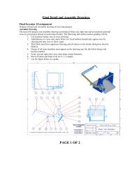
<strong>Assembly</strong> Drawing<br />
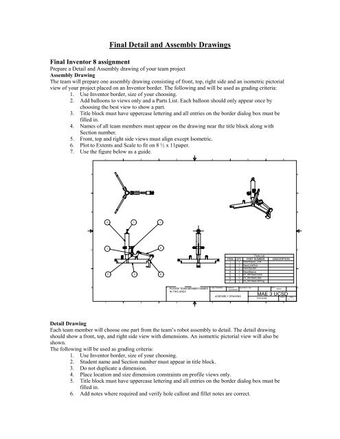
The team will prepare one assembly drawing consisting of front, top, right side <strong>and</strong> an isometric pictorial<br />
view of your project placed on an Inventor border. The following <strong>and</strong> will be used as grading criteria:<br />
1. Use Inventor border, size of your choosing.<br />
2. Add balloons to views only <strong>and</strong> a Parts List. Each balloon should only appear once by<br />
choosing the best view to show a part.<br />
3. Title block must have uppercase lettering <strong>and</strong> all entries on the border dialog box must be<br />
filled in.<br />
4. Names of all team members must appear on the drawing near the title block along with<br />
Section number.<br />
5. Front, top <strong>and</strong> right side views must align except Isometric.<br />
6. Plot to Extents <strong>and</strong> Scale to fit on 8 ½ x 11paper.<br />
7. Use the figure below as a guide.<br />
A<br />
B<br />
C<br />
D<br />
1<br />
1<br />
4 7<br />
1<br />
5<br />
3<br />
2<br />
2<br />
1<br />
2<br />
6<br />
3<br />
PLEASE TEAM MEMBER NAMES<br />
IN THIS AREA<br />
3<br />
4<br />
SECTION NO. Checked by Approved by - date<br />
Date<br />
D<br />
BUSSARD<br />
3/6/02<br />
4<br />
ITEM QTY<br />
Parts List<br />
PART NUMBER<br />
1 1 NewAdjust_Link<br />
2 1 NewLinkRod<br />
3 1 NewSpyder<br />
4 1 NewSleeve<br />
5 1 ch_09-NewCrank<br />
6 1 ch_09-NewClaw<br />
7 1 ch_09-NewLiftRing<br />
ASSEMBLY DRAWING<br />
5<br />
5<br />
MAE 3 <strong>UCSD</strong><br />
<strong>Detail</strong> Drawing<br />
Each team member will choose one part from the team’s robot assembly to detail. The detail drawing<br />
should show a front, top, <strong>and</strong> right side view with dimensions. An isometric pictorial view will also be<br />
shown.<br />
The following will be used as grading criteria:<br />
1. Use Inventor border, size of your choosing.<br />
2. Student name <strong>and</strong> Section number must appear in title block.<br />
3. Do not duplicate a dimension.<br />
4. Place location <strong>and</strong> size dimension constraints on profile views only.<br />
5. Title block must have uppercase lettering <strong>and</strong> all entries on the border dialog box must be<br />
filled in.<br />
6. Add notes where required <strong>and</strong> verify hole callout <strong>and</strong> fillet notes are correct.<br />
TEAM NAME<br />
6<br />
DESCRIPTION<br />
Edition Sheet<br />
1 / 1<br />
6<br />
A<br />
B<br />
C
7. All holes must have centerlines.<br />
8. Do not dimension to hidden lines.<br />
9. Place longer dimensions outside shorter dimensions.<br />
10. Place dimensions off views.<br />
11. Dimension circles by diameter <strong>and</strong> an arc by its radius.<br />
12. Use the figure below as a guide.<br />
D<br />
C<br />
B<br />
A<br />
6<br />
6<br />
Ø24.5<br />
4X R10<br />
2X Ø8.1<br />
2.89<br />
27.5<br />
5 4<br />
70<br />
120°<br />
Ø35<br />
27.5<br />
35<br />
5 4<br />
8<br />
22.5<br />
45<br />
30<br />
PROJECT<br />
FINAL DRAWING<br />
APPROVALS<br />
DATE<br />
DRAWN<br />
STUDENT NAME<br />
CHECKED<br />
BUSSARD<br />
3/6/02<br />
TITLE<br />
APPROVED<br />
3 2<br />
SIZE<br />
A3<br />
3 2<br />
MAE 3 <strong>UCSD</strong><br />
ASSIGNMENT 5<br />
DWG NO<br />
112-7654-02<br />
SCALE 1:1 SHEET 1 OF 1<br />
1<br />
1<br />
REV<br />
D<br />
C<br />
B<br />
A