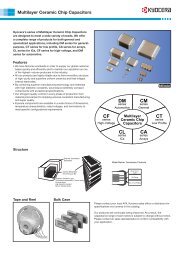
High-Efficiency Facemill MFPN - Kyocera
High-Efficiency Facemill MFPN - Kyocera
High-Efficiency Facemill MFPN - Kyocera

Create successful ePaper yourself
Turn your PDF publications into a flip-book with our unique Google optimized e-Paper software.
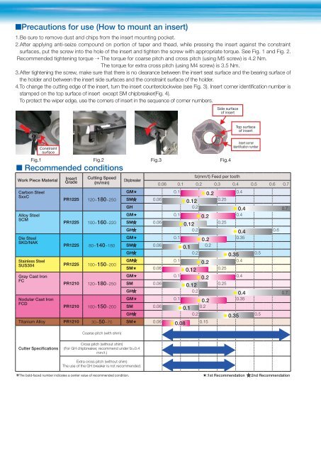
■Precautions for use (How to mount an insert)<br />
1.Be sure to remove dust and chips from the insert mounting pocket.<br />
2.After applying anti-seize compound on portion of taper and thead, while pressing the insert against the constraint<br />
surfaces, put the screw into the hole of the insert and tighten the screw with appropriate torque. See Fig. 1 and Fig. 2.<br />
Recommended tightening torque → The torque for coarse pitch and cross pitch (using M5 screw) is 4.2 Nm.<br />
The torque for extra cross pitch (using M4 screw) is 3.5 Nm.<br />
3.After tightening the screw, make sure that there is no clearance between the insert seat surface and the bearing surface of<br />
the holder and between the insert side surfaces and the constraint surface of the holder.<br />
4.To change the cutting edge of the insert, turn the insert counterclockwise (see Fig. 3). Insert corner identification number is<br />
stamped on the top surface of insert except SM chipbreaker(Fig. 4).<br />
To protect the wiper edge, use the corners of insert in the sequence of corner numbers.<br />
Constraint<br />
surface<br />
■ Recommended conditions<br />
Work Piece Material<br />
Insert<br />
Grade<br />
Cutting Speed<br />
(m/min)<br />
Chipbreaker<br />
fz(mm/t) Feed per tooth<br />
0.06 0.1 0.2 0.3 0.4 0.5 0.6 0.7<br />
Carbon Steel<br />
SxxC<br />
PR1225 120~180~250<br />
GM★<br />
SM 0.06<br />
0.1<br />
● 0.12<br />
● 0.2<br />
0.25<br />
0.4<br />
GH 0.2<br />
● 0.4 0.7<br />
Alloy Steel<br />
SCM<br />
PR1225 100~160~220<br />
GM★<br />
SM 0.06<br />
0.1 ● 0.2<br />
● 0.12<br />
0.25<br />
0.4<br />
GH 0.2 ● 0.4<br />
0.6<br />
Die Steel<br />
SKD/NAK<br />
PR1225 80~140~180<br />
GM★<br />
SM 0.06<br />
0.1<br />
● 0.1<br />
● 0.2<br />
0.2<br />
0.35<br />
GH 0.2 ● 0.35 0.5<br />
Stainless Steel<br />
SUS304 PR1225 100~150~200<br />
GM<br />
SM★ 0.06<br />
0.1 ● 0.2<br />
● 0.12<br />
0.25<br />
0.4<br />
Gray Cast Iron<br />
FC<br />
PR1210 120~180~250<br />
GM★<br />
SM 0.06<br />
0.1 ● 0.2<br />
● 0.12 0.25<br />
0.4<br />
GH 0.2<br />
● 0.4 0.7 0.7<br />
Nodular Cast Iron<br />
FCD<br />
PR1210 100~150~200<br />
GM★<br />
SM 0.06<br />
0.1<br />
● 0.1<br />
● 0.2<br />
0.2<br />
0.35<br />
GH 0.2 ● 0.35 0.5<br />
Titanium Alloy PR1210 30~50~70 SM★ 0.06 ● 0.08 0.15<br />
Cutter Specifications<br />
Coarse pitch (with shim)<br />
Cross pitch (without shim)<br />
(For GH chipbreaker, recommend under fz=0.4<br />
mm/t.)<br />
Extra cross pitch (without shim)<br />
The use of the GH breaker is not recommended.<br />
Side surface<br />
of insert<br />
Fig.1 Fig.2 Fig.3 Fig.4<br />
Top surface<br />
of insert<br />
Insert corner<br />
identication number<br />
❋The bold-faced number indicates a center value of recommended condition. ★:1st Recommendation :2nd Recommendation