High-Efficiency Facemill MFPN - Kyocera
High-Efficiency Facemill MFPN - Kyocera
High-Efficiency Facemill MFPN - Kyocera

You also want an ePaper? Increase the reach of your titles
YUMPU automatically turns print PDFs into web optimized ePapers that Google loves.
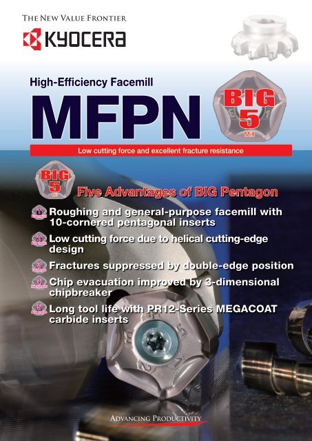
<strong>High</strong>-<strong>Efficiency</strong> <strong>Facemill</strong><br />
<strong>MFPN</strong><br />
Low cutting force and excellent fracture resistance<br />
1<br />
Economical<br />
2<br />
New design<br />
3<br />
Toughness<br />
4<br />
New chipbreaker<br />
5<br />
New grades<br />
BIG<br />
5<br />
5Mill Mill<br />
BIG<br />
5<br />
5Mill Mill<br />
Five Advantages of BIG Pentagon<br />
Roughing and general-purpose facemill with<br />
10-cornered pentagonal inserts<br />
Low cutting force due to helical cutting-edge<br />
design<br />
Fractures suppressed by double-edge position<br />
Chip evacuation improved by 3-dimensional<br />
chipbreaker<br />
Long tool life with PR12-Series MEGACOAT<br />
carbide inserts
1<br />
1<br />
2<br />
3<br />
Wiper edge<br />
BIG<br />
5<br />
5Mill Mill<br />
Economical<br />
New design<br />
Toughness<br />
Pioneering a new era<br />
Roughing and general-purpose facemill with<br />
10-cornered pentagonal inserts<br />
ap (mm) Depth of cut<br />
12<br />
10<br />
8<br />
6<br />
5<br />
4<br />
3<br />
2<br />
0.5<br />
Two-face restraint<br />
Major<br />
cutting edge<br />
BI<br />
Low cutting force due to helical cutting-edge<br />
5<br />
design<br />
MSRS<br />
Conventional<br />
0.06 0.1 0.2 0.3 0.4 0.5 0.6<br />
fz (mm/t) Feed per tooth<br />
+10°<br />
(A.R.)<br />
Main cutting edge<br />
No. 1<br />
<strong>MFPN</strong><br />
<strong>High</strong> feed machining substantially improves efficiency<br />
NEW<br />
<strong>MFPN</strong><br />
■Pentagonal double-sided tip excellent for<br />
constraining stability<br />
■10-cornered insert cuts cost per corner<br />
■Helical cutting-edge design with low<br />
cutting force reduces chattering<br />
■Helical cutting-edge design<br />
·<strong>High</strong> rake angle (A.R. Max. +10°)<br />
0.7<br />
Cutting edge<br />
angle 45°<br />
BI<br />
Principal force<br />
Feed force<br />
Back force 5M<br />
Fractures suppressed with double-edge position<br />
■Double-edge position<br />
·Major cutting edge makes chips thin,<br />
thereby reducing impact load at entrance<br />
and exit of workpiece<br />
Double-edge position<br />
Five Advantages of BIG Pentagon<br />
Main cutting edge<br />
No. 2<br />
Cutting force comparison (N)<br />
2000<br />
1600<br />
1200<br />
800<br />
400<br />
●Cutting force comparison<br />
0<br />
<strong>High</strong>ly stabilized accuracy due to two-face<br />
constraint facing the major cutting edge<br />
16% reduction in comparison<br />
with competitor A<br />
14% reduction in<br />
comparison with GM<br />
GM SM<br />
Competitor A Competitor B<br />
●Cutting conditions<br />
Workpiece :S50C<br />
Vc=150m/min, fz=0.1mm/t, apxae=5x105 mm, Machine :M/C(BT50)<br />
●Fracture resistance comparison<br />
PNMU1205ANER-GM<br />
(PR1225)<br />
Competitor C<br />
(PVD negative insert)<br />
Competitor D<br />
(PVD negative insert)<br />
No. of impacts<br />
0 5 10 15 20<br />
×<br />
×<br />
×<br />
×<br />
×<br />
×<br />
fz=0.5mm/t fz=0.6mm/t fz=0.7mm/t<br />
●Cutting conditions<br />
Workpiece :SCM440(38~42HS)<br />
Machine :BT50 M/C<br />
Vc=100m/min, fz=0.5~0.7mm/t,<br />
apxae=2x100mm (workpiece with 20mm width slot)<br />
0.5mm/t<br />
0.6mm/t<br />
0.7mm/t<br />
:No cracks<br />
× : Insert cracks
AT Hard<br />
ill<br />
<strong>High</strong>-<strong>Efficiency</strong> <strong>Facemill</strong><br />
<strong>MFPN</strong><br />
Milling-Facing PeNtagonal type<br />
5<br />
New grades<br />
G<br />
4<br />
New<br />
chipbreaker<br />
Long tool life with PR12-Series<br />
MEGACOAT carbide inserts<br />
■MEGACOAT<br />
·Long tool life and high-speed milling due to high hardness and<br />
high oxidation resistance<br />
●Wear comparison<br />
Flank wear [mm]<br />
●Cutting conditions<br />
Workpiece :SCM440H<br />
Vc=250m/min, fz =0.12mm/t<br />
apxae=2x85mm, Cutter Dia.:125mm<br />
Cut distance per 1 path:340mm<br />
3-dimensional chipbreaker<br />
improves chip evacuation<br />
■Smooth chip evacuation reduces chip-biting<br />
·3-types of chipbreakers enable coverage of a wide range<br />
of milling conditions<br />
Chipbreaker Applications Shape<br />
GM General<br />
SM<br />
GH<br />
0.30<br />
0.25<br />
0.20<br />
0.15<br />
0.10<br />
0.05<br />
0.00<br />
0 20 40 60 80<br />
Cutting time [min]<br />
Low cutting<br />
force<br />
Heavy<br />
milling<br />
ap (mm) Depth of cut<br />
6<br />
3<br />
1<br />
Competitor E<br />
Competitor F<br />
Competitor G<br />
PR1225<br />
SM<br />
Hardness(GPa)<br />
40<br />
30<br />
20<br />
10<br />
GM<br />
TiC<br />
TiCN<br />
MEGACOAT<br />
TiN<br />
TiAlN<br />
(ref:carbide)<br />
0 200 400 600 800 1000 1200<br />
Oxidation temperature (˚C)<br />
GH<br />
MEGACOAT<br />
Insert grades Workpiece<br />
PR1225<br />
PR1210<br />
Steel / Stainless steel<br />
Cast iron / Titanium alloy<br />
0.06 0.1 0.2 0.3 0.4 0.5 0.6 0.7<br />
fz (mm/t) Feed per tooth<br />
2
3<br />
■<strong>MFPN</strong>45<br />
●Holder Dimension<br />
Bore Dia. Inch spec<br />
mm spec<br />
Coarse pitch<br />
Cross pitch<br />
Extra cross pitch<br />
Coarse pitch<br />
Cross pitch<br />
Extra cross pitch<br />
Description<br />
Stock<br />
E<br />
a<br />
No.of<br />
Insert<br />
ød<br />
b<br />
ød2<br />
ød1<br />
øD<br />
øD1<br />
45˚<br />
6<br />
H<br />
E<br />
a<br />
Rake<br />
Angle(°)<br />
ød<br />
b<br />
ød1<br />
øD<br />
øD1<br />
Dimension(mm)<br />
45˚<br />
6<br />
H<br />
A.R. R.R.<br />
max +10°<br />
Fig.1 Fig.2 Fig.3<br />
øD øD1 ød ød1 ød2 H E a b ød3 ød4<br />
E<br />
øD=63 -10°<br />
øD=80 -8°<br />
øD=100-250 -6°<br />
ød<br />
b<br />
ød2<br />
ød1<br />
øD<br />
øD1<br />
ød3<br />
ød4<br />
45˚<br />
Shape Weight<br />
(kg)<br />
<strong>MFPN</strong> 45080R-5T<br />
45100R-6T<br />
45125R-7T<br />
●<br />
●<br />
●<br />
5<br />
6<br />
7<br />
80<br />
100<br />
125<br />
93<br />
113<br />
138<br />
25.4<br />
31.75<br />
38.1<br />
22<br />
48<br />
58<br />
13<br />
-<br />
50<br />
27<br />
32<br />
36<br />
6<br />
8<br />
10<br />
9.5<br />
12.7<br />
15.9<br />
- -<br />
Fig.1<br />
Fig.2<br />
1.1<br />
1.4<br />
2.6<br />
45160R-8T<br />
45200R-10T<br />
45250R-12T<br />
●<br />
●<br />
●<br />
8<br />
10<br />
12<br />
160<br />
200<br />
250<br />
173<br />
213<br />
263<br />
50.8<br />
47.625<br />
72<br />
110 101.6<br />
63<br />
38<br />
40<br />
11<br />
14<br />
19.1<br />
25.4 18 26 Fig.3<br />
4.0<br />
6.7<br />
9.4<br />
<strong>MFPN</strong> 45080R-6T<br />
45100R-8T<br />
45125R-10T<br />
●<br />
●<br />
●<br />
6<br />
8<br />
10<br />
80<br />
100<br />
125<br />
93<br />
113<br />
138<br />
25.4<br />
31.75<br />
38.1<br />
22<br />
48<br />
58<br />
13<br />
-<br />
50<br />
27<br />
32<br />
36<br />
6<br />
8<br />
10<br />
9.5<br />
12.7<br />
15.9<br />
- -<br />
Fig.1<br />
Fig.2<br />
1.1<br />
1.4<br />
2.7<br />
45160R-12T<br />
45200R-14T<br />
45250R-16T<br />
●<br />
●<br />
●<br />
12<br />
14<br />
16<br />
160<br />
200<br />
250<br />
173<br />
213<br />
263<br />
50.8<br />
47.625<br />
72<br />
110 101.6<br />
63<br />
38<br />
40<br />
11<br />
14<br />
19.1<br />
25.4 18 26 Fig.3<br />
4.0<br />
6.9<br />
9.6<br />
<strong>MFPN</strong> 45080R-8T<br />
45100R-10T<br />
45125R-13T<br />
●<br />
●<br />
●<br />
8<br />
10<br />
13<br />
80<br />
100<br />
125<br />
93<br />
113<br />
138<br />
25.4<br />
31.75<br />
38.1<br />
22<br />
48<br />
58<br />
13<br />
-<br />
50<br />
27<br />
32<br />
36<br />
6<br />
8<br />
10<br />
9.5<br />
12.7<br />
15.9<br />
- -<br />
Fig.1<br />
Fig.2<br />
1.1<br />
1.3<br />
2.7<br />
45160R-16T<br />
45200R-18T<br />
45250R-20T<br />
●<br />
●<br />
●<br />
16<br />
18<br />
20<br />
160<br />
200<br />
250<br />
173<br />
213<br />
263<br />
50.8<br />
47.625<br />
72<br />
110 101.6<br />
63<br />
38<br />
40<br />
11<br />
14<br />
19.1<br />
25.4 18 26 Fig.3<br />
4.0<br />
6.9<br />
9.6<br />
<strong>MFPN</strong> 45063R-4T-M<br />
45080R-5T-M<br />
45100R-6T-M<br />
45125R-7T-M<br />
45160R-8T-M<br />
45200R-10T-M<br />
45250R-12T-M<br />
●<br />
●<br />
●<br />
●<br />
●<br />
●<br />
●<br />
4<br />
5<br />
6<br />
7<br />
8<br />
10<br />
12<br />
63<br />
80<br />
100<br />
125<br />
160<br />
200<br />
250<br />
76<br />
93<br />
113<br />
138<br />
173<br />
213<br />
263<br />
22<br />
27<br />
32<br />
40<br />
60<br />
19<br />
22<br />
48<br />
58<br />
68<br />
110<br />
11<br />
13<br />
-<br />
66.7<br />
101.6<br />
40<br />
50<br />
63<br />
21<br />
24<br />
30<br />
32<br />
40<br />
6.3<br />
7<br />
8<br />
9<br />
14<br />
10.4<br />
12.4<br />
14.4<br />
16.4<br />
25.7<br />
-<br />
14<br />
18<br />
-<br />
20<br />
26<br />
Fig.1<br />
Fig.2<br />
Fig.3<br />
0.5<br />
1.1<br />
1.4<br />
2.6<br />
3.8<br />
6.4<br />
9.1<br />
<strong>MFPN</strong> 45063R-5T-M<br />
45080R-6T-M<br />
45100R-8T-M<br />
45125R-10T-M<br />
45160R-12T-M<br />
45200R-14T-M<br />
45250R-16T-M<br />
●<br />
●<br />
●<br />
●<br />
●<br />
●<br />
●<br />
5<br />
6<br />
8<br />
10<br />
12<br />
14<br />
16<br />
63<br />
80<br />
100<br />
125<br />
160<br />
200<br />
250<br />
76<br />
93<br />
113<br />
138<br />
173<br />
213<br />
263<br />
22<br />
27<br />
32<br />
40<br />
60<br />
19<br />
22<br />
48<br />
58<br />
68<br />
110<br />
11<br />
13<br />
-<br />
66.7<br />
101.6<br />
40<br />
50<br />
63<br />
21<br />
24<br />
30<br />
32<br />
40<br />
6.3<br />
7<br />
8<br />
9<br />
14<br />
10.4<br />
12.4<br />
14.4<br />
16.4<br />
25.7<br />
-<br />
14<br />
18<br />
-<br />
20<br />
26<br />
Fig.1<br />
Fig.2<br />
Fig.3<br />
0.5<br />
1.0<br />
1.4<br />
2.5<br />
3.8<br />
6.5<br />
9.1<br />
<strong>MFPN</strong> 45063R-6T-M<br />
45080R-8T-M<br />
45100R-10T-M<br />
45125R-13T-M<br />
45160R-16T-M<br />
45200R-18T-M<br />
45250R-20T-M<br />
●<br />
●<br />
●<br />
●<br />
●<br />
●<br />
●<br />
6<br />
8<br />
10<br />
13<br />
16<br />
18<br />
20<br />
63<br />
80<br />
100<br />
125<br />
160<br />
200<br />
250<br />
76<br />
93<br />
113<br />
138<br />
173<br />
213<br />
263<br />
22<br />
27<br />
32<br />
40<br />
60<br />
19<br />
22<br />
48<br />
58<br />
68<br />
110<br />
11<br />
13<br />
-<br />
-<br />
66.7<br />
101.6<br />
40<br />
50<br />
63<br />
21<br />
24<br />
30<br />
32<br />
40<br />
6.3<br />
7<br />
8<br />
9<br />
14<br />
10.4<br />
12.4<br />
14.4<br />
16.4<br />
25.7<br />
-<br />
14<br />
18<br />
-<br />
20<br />
26<br />
Fig.1<br />
Fig.2<br />
Fig.3<br />
0.5<br />
1.1<br />
1.3<br />
2.6<br />
3.9<br />
6.6<br />
9.3<br />
6<br />
H<br />
Shim<br />
Yes<br />
-<br />
-<br />
Yes<br />
-<br />
-<br />
●:Std. Stock
■Spare Parts<br />
●Spare parts (mm / inch common spec)<br />
Coarse pitch<br />
Cross pitch<br />
Extra cross pitch<br />
MP-1<br />
Description<br />
Clamp<br />
Screw<br />
Wrench<br />
TT DTM<br />
Spare Parts<br />
Shim Shim Screw Wrench<br />
Anti-seize<br />
Compound<br />
MP-1<br />
Arbar<br />
Clamp Screw<br />
<strong>MFPN</strong> 45063R-4T-M<br />
HH10x30<br />
<strong>MFPN</strong> 45080R-5T-(M) SB-50140TR TT-15 <strong>MFPN</strong>-45 SPW-7050 LW-5 HH12x40<br />
<strong>MFPN</strong> 45100R-6T-(M)<br />
45250R-12T-(M)<br />
for Insert Clamp<br />
Recommended torque is<br />
4.2 Nm.<br />
-<br />
for Shim Clamp<br />
Recommended torque is<br />
6.0 Nm.<br />
MP-1<br />
-<br />
<strong>MFPN</strong> 45063R-5T-M<br />
HH10x30<br />
<strong>MFPN</strong> 45080R-6T-(M) SB-50140TR TT-15 HH12x40<br />
<strong>MFPN</strong> 45100R-8T-(M) for Insert Clamp<br />
- - - - MP-1<br />
Recommended torque is<br />
-<br />
45250R-16T-(M)<br />
4.2 Nm.<br />
<strong>MFPN</strong> 45063R-6T-M<br />
HH10x30<br />
<strong>MFPN</strong> 45080R-8T-(M) SB-40140TRN - DTM-15 HH12x40<br />
<strong>MFPN</strong> 45100R-10T-(M)<br />
for Insert Clamp<br />
- - - MP-1<br />
45250R-20T-(M)<br />
Recommended torque is<br />
3.5 Nm.<br />
-<br />
~<br />
~<br />
~<br />
∙Coat Anti-seize Compound (MP-1) thinly on portion of taper and thread when insert is fixed.<br />
■Insert description Classification of usage P<br />
●Milling Inserts (with hole) ★ Roughing / 1st Choice<br />
Roughing / 2nd Choice<br />
■ Finishing / 1st Choice<br />
Finishing / 2nd Choice<br />
Shape<br />
Handled insert indicates Right-Hand<br />
General<br />
Low cutting force<br />
Tough Edge (for heavy milling)<br />
Z<br />
Z<br />
Z<br />
X<br />
X<br />
X<br />
A<br />
A<br />
A<br />
T<br />
T<br />
T<br />
Ød<br />
Ød<br />
Ød<br />
(Hardened material is applicable only under<br />
45HRC)<br />
Description<br />
PNMU 1205ANER-GM<br />
Steel ★<br />
Die Steel ★<br />
M Stainless Steel ★<br />
K<br />
Gray Cast Iron<br />
Nodular Cast Iron<br />
★<br />
★<br />
N Non-ferrous Material<br />
S<br />
Heat-resistant Alloy<br />
Titanium alloy<br />
★<br />
★<br />
H Hardened material<br />
Dimension(mm) MEGACOAT<br />
A T ød X Z PR1225 PR1210<br />
17.88 5.56<br />
● ●<br />
PNMU 1205ANER-SM 6.2 2.0 2.0 ● ●<br />
PNMU 1205ANER-GH 17.98 6.17 ● ●<br />
●Reference for selecting a facemill and insert suitable for each milling purpose<br />
Milling Purpose<br />
General milling for steel and alloy steel<br />
Steel and alloy steel (to prevent chattering due to low rigidity<br />
machine or poor clamping power)<br />
Productivity oriented (Running cost decrease) (Over ap=4 mm,<br />
over fz=0.35 mm/t)<br />
Genral milling for stainless steel<br />
Stainless steel (to prevent chattering due to low rigidity<br />
machine or poor clamping power)<br />
Cast iron (for processing efficiency improvement)<br />
Cast iron (Over ap=4 mm, over fz=0.35 mm/t)<br />
Coarse<br />
pitch<br />
<strong>Facemill</strong>-type Chipbreaker<br />
Cross pitch<br />
Extra cross<br />
pitch<br />
●:Std. Stock<br />
GM SM GH<br />
4
5<br />
■Case studies<br />
·Construction machine part<br />
·Vc=170m/min<br />
·apxae=4x10mm<br />
·fz=0.3mm/t<br />
·Vf=1350mm/min<br />
·DRY<br />
·Cutter<br />
<strong>MFPN</strong>45125R-10T<br />
(10 edges)<br />
·Insert<br />
PNMU1205ANER-GM<br />
(PR1225)<br />
<strong>MFPN</strong><br />
(PR1225)<br />
Competitor H<br />
SS400<br />
Face milling (with meltdown surface)<br />
1500<br />
·<strong>MFPN</strong> facemill enables stable milling due to reduced chip-biting and<br />
edge cracks<br />
·<strong>MFPN</strong> facemill, no chattering, showed 3 times longer tool life than<br />
competitor<br />
·Construction machine part<br />
·Vc=175m/min<br />
·apxae=1.5x100mm<br />
·fz=0.19mm/t<br />
·Vf=790mm/min<br />
·DRY<br />
·Cutter<br />
<strong>MFPN</strong>45160R-12T<br />
(12 edges)<br />
·Insert<br />
PNMU1205ANER-GM<br />
(PR1225)<br />
<strong>MFPN</strong><br />
(PR1225)<br />
Competitor J<br />
3pcs/edge<br />
Alloy steel<br />
Total D.O.C.:15mm<br />
2pcs/edge<br />
1pcs/edge<br />
1pcs/edge<br />
100<br />
200<br />
3 times<br />
longer tool life<br />
Evaluation by the user<br />
·<strong>MFPN</strong> facemill showed 2 times longer tool life than competitor<br />
·Competitor caused cracks by chip-biting. <strong>MFPN</strong> facemill had no<br />
cracks and allowed stable milling<br />
·<strong>MFPN</strong> facemill enabled twice the table feed rate compared with the<br />
competitor. Milling efficiency improved two-fold.<br />
100<br />
ø400<br />
2 times<br />
longer tool life<br />
Evaluation by the user<br />
·Pipe<br />
·Vc=180m/min<br />
·apxae=2x80mm<br />
·fz=0.44mm/t<br />
·Vf=2010mm/min<br />
·DRY<br />
·Cutter<br />
<strong>MFPN</strong>45125R-10T<br />
(10 edges)<br />
·Insert<br />
PNMU1205ANER-GM<br />
(PR1210)<br />
<strong>MFPN</strong><br />
(PR1210)<br />
Competitor I<br />
FCD450<br />
ø3000<br />
·<strong>MFPN</strong> facemill showed 1.5 times longer tool life than the competitor<br />
·<strong>High</strong> feed rate of <strong>MFPN</strong> allowed 1.3 times higher milling efficiency<br />
compared to the competitor<br />
·Press die<br />
·Vc=130m/min<br />
·apxae=6x150mm<br />
·fz=0.15mm/t<br />
·Vf=460mm/min<br />
·DRY<br />
·Cutter<br />
<strong>MFPN</strong>45160R-12T<br />
(12 edges)<br />
·Insert<br />
PNMU1205ANER-GM<br />
(PR1210)<br />
<strong>MFPN</strong><br />
(PR1225)<br />
Competitor K<br />
FCD600<br />
Face milling<br />
3pcs/edge<br />
2pcs/edge<br />
Cutting time<br />
128 minutes<br />
3000<br />
Cutting time<br />
167 minutes<br />
80<br />
2000<br />
1.5 times<br />
longer tool life<br />
Evaluation by the user<br />
·<strong>High</strong>ly stable milling into the entrance of workpiece and less vibration<br />
than the competitor<br />
·Cleanly curled chips which barely cause chip-biting<br />
·Cutting speed has been changed Vc=110 m/min of conventional<br />
competitor's to Vc=130 m/min, thereby the milling efficiency of<br />
<strong>MFPN</strong> increased 1.2 times<br />
300<br />
Milling efficiency<br />
increased 1.2 times<br />
Evaluation by the user
■Case studies<br />
·Plate<br />
·Vc=230m/min<br />
·apxae=5.0x80mm<br />
·fz=0.19mm/t<br />
·Vf=1090mm/min<br />
·DRY<br />
·Cutter<br />
<strong>MFPN</strong>45160R-12T<br />
(12 edges)<br />
·Insert<br />
PNMU1205ANER-SM<br />
(PR1225)<br />
<strong>MFPN</strong><br />
(PR1225)<br />
Competitor L<br />
(for roughing)<br />
SS400<br />
2000<br />
·<strong>MFPN</strong> facemill causes no vibration, enabling stable milling, even<br />
though the number of cutting edges of facemill has been increased<br />
by 4 and the feed per tooth has been increased by 1.3 times<br />
·Does not generate much heat after milling and obtains the lustrous<br />
surface finish without burrs<br />
·Milling efficiency increased 2.6 times with the high cutting conditions<br />
·Plate<br />
·Vc=180m/min<br />
·apxae=3x80mm<br />
·fz=0.15mm/t<br />
·Vf=690mm/min<br />
·DRY<br />
·Cutter<br />
<strong>MFPN</strong>45125R-10T<br />
(10 edges)<br />
·Insert<br />
PNMU1205ANER-GM<br />
(PR1225)<br />
[Conventional]<br />
Vc=140m/min<br />
apxae=3x80mm<br />
fz=0.11mm/t<br />
(Vf=230mm/min)<br />
Cutting time 7.3<br />
minutes<br />
(4 passes)<br />
Cutting time 19 minutes<br />
(4 passes)<br />
SCM415<br />
300<br />
80<br />
Milling efficiency<br />
increased 2.6 times<br />
Evaluation by the user<br />
·Even if the cutting speed and feed rate are raised up to the level of the<br />
conventional tool, the tool life of <strong>MFPN</strong> remains unchanged and milling<br />
efficiency increases by 2.6 times<br />
·<strong>MFPN</strong> vibrates less right at entrance and exit on workpiece with reduced<br />
cutting sound<br />
400<br />
Evaluation by the user<br />
· Shaft (End face milling)<br />
·Vc=140m/min<br />
·apxae=0.4x50mm<br />
·fz=0.19mm/t<br />
·Vf=635mm/min<br />
·DRY<br />
·Cutter<br />
<strong>MFPN</strong>45080R-6T<br />
(6 edges)<br />
·Insert<br />
PNMU1205ANER-SM<br />
(PR1225)<br />
Alloy steel<br />
End face milling<br />
·Although the conventional tool causes chattering, <strong>MFPN</strong> facemill<br />
suppresses chattering, enabling stable milling<br />
·Even if the feed rate is raised to 1.9 times, the insert wears less and<br />
there is no cracks on the insert<br />
·Both the milling efficiency and the tool life have been improved<br />
·Case<br />
·Vc=90m/min<br />
·apxae=0.4x50mm<br />
·fz=0.19mm/t<br />
·Vf=410mm/min<br />
·DRY<br />
·Cutter<br />
<strong>MFPN</strong>45080R-6T<br />
(6 edges)<br />
·Insert<br />
PNMU1205ANER-SM<br />
(PR1225)<br />
<strong>MFPN</strong><br />
(PR1225)<br />
Competitor M<br />
(for roughing)<br />
SUS304<br />
500<br />
800<br />
1.5pcs/edge<br />
1pcs/edge<br />
ø90<br />
Evaluation by the user<br />
·Even when the cutting depth, cutting speed and feed rate cannot be<br />
raised due to the low rigidity of a workpiece, <strong>MFPN</strong> facemill enables<br />
stable milling without chattering and also has an improved tool life of<br />
1.5 times<br />
600<br />
Milling efficiency<br />
increased 1.5 times<br />
Evaluation by the user<br />
6
■Precautions for use (How to mount an insert)<br />
1.Be sure to remove dust and chips from the insert mounting pocket.<br />
2.After applying anti-seize compound on portion of taper and thead, while pressing the insert against the constraint<br />
surfaces, put the screw into the hole of the insert and tighten the screw with appropriate torque. See Fig. 1 and Fig. 2.<br />
Recommended tightening torque → The torque for coarse pitch and cross pitch (using M5 screw) is 4.2 Nm.<br />
The torque for extra cross pitch (using M4 screw) is 3.5 Nm.<br />
3.After tightening the screw, make sure that there is no clearance between the insert seat surface and the bearing surface of<br />
the holder and between the insert side surfaces and the constraint surface of the holder.<br />
4.To change the cutting edge of the insert, turn the insert counterclockwise (see Fig. 3). Insert corner identification number is<br />
stamped on the top surface of insert except SM chipbreaker(Fig. 4).<br />
To protect the wiper edge, use the corners of insert in the sequence of corner numbers.<br />
Constraint<br />
surface<br />
■ Recommended conditions<br />
Work Piece Material<br />
Insert<br />
Grade<br />
Cutting Speed<br />
(m/min)<br />
Chipbreaker<br />
fz(mm/t) Feed per tooth<br />
0.06 0.1 0.2 0.3 0.4 0.5 0.6 0.7<br />
Carbon Steel<br />
SxxC<br />
PR1225 120~180~250<br />
GM★<br />
SM 0.06<br />
0.1<br />
● 0.12<br />
● 0.2<br />
0.25<br />
0.4<br />
GH 0.2<br />
● 0.4 0.7<br />
Alloy Steel<br />
SCM<br />
PR1225 100~160~220<br />
GM★<br />
SM 0.06<br />
0.1 ● 0.2<br />
● 0.12<br />
0.25<br />
0.4<br />
GH 0.2 ● 0.4<br />
0.6<br />
Die Steel<br />
SKD/NAK<br />
PR1225 80~140~180<br />
GM★<br />
SM 0.06<br />
0.1<br />
● 0.1<br />
● 0.2<br />
0.2<br />
0.35<br />
GH 0.2 ● 0.35 0.5<br />
Stainless Steel<br />
SUS304 PR1225 100~150~200<br />
GM<br />
SM★ 0.06<br />
0.1 ● 0.2<br />
● 0.12<br />
0.25<br />
0.4<br />
Gray Cast Iron<br />
FC<br />
PR1210 120~180~250<br />
GM★<br />
SM 0.06<br />
0.1 ● 0.2<br />
● 0.12 0.25<br />
0.4<br />
GH 0.2<br />
● 0.4 0.7 0.7<br />
Nodular Cast Iron<br />
FCD<br />
PR1210 100~150~200<br />
GM★<br />
SM 0.06<br />
0.1<br />
● 0.1<br />
● 0.2<br />
0.2<br />
0.35<br />
GH 0.2 ● 0.35 0.5<br />
Titanium Alloy PR1210 30~50~70 SM★ 0.06 ● 0.08 0.15<br />
Cutter Specifications<br />
Coarse pitch (with shim)<br />
Cross pitch (without shim)<br />
(For GH chipbreaker, recommend under fz=0.4<br />
mm/t.)<br />
Extra cross pitch (without shim)<br />
The use of the GH breaker is not recommended.<br />
Side surface<br />
of insert<br />
Fig.1 Fig.2 Fig.3 Fig.4<br />
Top surface<br />
of insert<br />
Insert corner<br />
identication number<br />
❋The bold-faced number indicates a center value of recommended condition. ★:1st Recommendation :2nd Recommendation