DRAFT - Danfoss Heating for consumers
DRAFT - Danfoss Heating for consumers
DRAFT - Danfoss Heating for consumers

You also want an ePaper? Increase the reach of your titles
YUMPU automatically turns print PDFs into web optimized ePapers that Google loves.
*087R9781*<br />
*VIKTG202*<br />
<strong>Danfoss</strong> can accept no responsibility <strong>for</strong> possible errors in catalogues, brochures and other printed material. <strong>Danfoss</strong> reserves the right to alter its products without notice. This also applies to products<br />
already on order provided that such alterations can be made without subsequential changes being necessary in specications already agreed.<br />
All trademarks in this material are property of the respective companies. <strong>Danfoss</strong> and the <strong>Danfoss</strong> logotype are trademarks of <strong>Danfoss</strong> A/S. All rights reserved.<br />
52 VI.KT.G2.02 © <strong>Danfoss</strong> 05/2007 DH-SMT/DK<br />
✐<br />
<br />
DH-SMT/DK VI.KT.G2.02 © <strong>Danfoss</strong> 05/2007<br />
Instructions<br />
ECL Com<strong>for</strong>t 110<br />
Application 130<br />
Weather compensated flow temperature<br />
control of heating and boiler systems<br />
User guide,<br />
Installation & Maintenance
How to navigate?<br />
What do the symbols mean?<br />
<br />
<br />
<br />
Adjust temperatures and values.<br />
Switch between menu lines.<br />
Select / return.<br />
2 sec.<br />
Return to daily user menu.<br />
The desired flow temperature is influenced by <strong>for</strong> example room or return temperature.<br />
The actuator closes the control valve.<br />
The actuator opens the control valve.<br />
The actuator does not activate the valve.<br />
The pump is ON.<br />
The pump is OFF.<br />
The controller is in setback mode.<br />
The controller is in pre-setback mode (the symbol is blinking).<br />
The controller is in com<strong>for</strong>t mode.<br />
The controller is in pre-com<strong>for</strong>t mode (the symbol is blinking).<br />
Safety Note<br />
To avoid injury of persons and damages to the device, it is absolutely necessary to read and<br />
observe these instructions carefully. The warning sign is used to emphasize special conditions<br />
that should be taken into consideration.<br />
This symbol indicates that this particular piece of in<strong>for</strong>mation should be read with<br />
special attention.<br />
VI.KT.G2.02 © <strong>Danfoss</strong> 05/2007 DH-SMT/DK<br />
Disposal Instruction<br />
Equipment containing electrical components shall not be disposed together with<br />
domestic waste.<br />
It must be collected separately with other electrical and electronic waste according to<br />
local legislation.<br />
DH-SMT/DK VI.KT.G2.02 © <strong>Danfoss</strong> 05/2007
50 VI.KT.G2.02 © <strong>Danfoss</strong> 05/2007 DH-SMT/DK<br />
Table of Contents<br />
Line Page<br />
Introduction.................................................................................................. 6<br />
Settings overview 7<br />
Daily use........................................................................................................ 8<br />
Temperatures 8<br />
Select control mode 9<br />
Set your personal schedule 9<br />
Maintenance ............................................................................................... 11<br />
Date - time 1000 11<br />
Flow temp. (flow temperature control) 2000 11<br />
Slope 2175 12<br />
Displace (parallel displacement) 2176 14<br />
Temp. min. (flow temp. limit, min.) 2177 14<br />
Temp. max. (flow temp. limit, max.) 2178 14<br />
Room T limit (room temperature limitation) 3000 15<br />
Intgr. time (time constant <strong>for</strong> room temp.) 3015 17<br />
Gain - max. (room temp. limitation, max.) 3182 17<br />
Gain - min. (room temp. limitation, min.) 3183 17<br />
Return T limit (return temp. limitation) 4000 18<br />
Limit (return temp. limitation) 4030 18<br />
Gain - max. (return temp. limitation - max. influence) 4035 19<br />
Gain - min. (return temp. limitation - min. influence) 4036 19<br />
Intgr. time (time constant <strong>for</strong> return temp. limitation) 4037 20<br />
Priority (priority <strong>for</strong> return temp. limitation) 4085 20<br />
Optimize 5000 21<br />
Auto-reduct (setback temp. dependent on outdoor temp.) 5011 21<br />
Boost 5012 21<br />
Ramp (reference ramping) 5013 22<br />
Optimizer (optimizing time constant) 5014 22<br />
Based on (optimization based on room / outdoor temp.) 5020 23<br />
Total stop 5021 24<br />
S1 T filter (outdoor temp. filter) 5081 24<br />
Cut-out (limit <strong>for</strong> heating cut-out) 5179 25<br />
Control param. (control parameters) 6000 26<br />
Motor prot. (motor protection) 6174 26<br />
Xp (proportional band) 6184 26<br />
Tn (integration time constant) 6185 26<br />
M1 run (running time of the motorized control valve) 6186 26<br />
Nz (neutral zone) 6187 27<br />
DH-SMT/DK VI.KT.G2.02 © <strong>Danfoss</strong> 05/2007
Application 7000 29<br />
ECA address (choice of room panel / remote control) 7010 29<br />
P1 exercise (pump exercise) 7022 29<br />
M1 exercise (valve exercise) 7023 29<br />
Actuator (gear motor / thermo actuator) 7024 29<br />
DHW prior. (closed valve / normal operation) 7052 30<br />
P1 frost T (frost protection) 7077 30<br />
P1 heat T (heat demand) 7078 31<br />
Standby T (standby temperature) 7093 31<br />
Ext. (external override) 7141 31<br />
Knee point 7162 32<br />
Min. on time (min. activation time gear motor) 7189 32<br />
Daylight (daylight saving time changeover) 7198 32<br />
ECL address (master / slave address) 7199 33<br />
Type 7600 33<br />
Service 8000 34<br />
Code no. 8300 34<br />
Ver. (version no.) 8301 34<br />
Backlight (display brightness) 8310 34<br />
Contrast (display contrast) 8311 34<br />
Language 8315 35<br />
MOD address (MODBUS address) 8320 35<br />
Installation..................................................................................................36<br />
Mounting the ECL Com<strong>for</strong>t controller 36<br />
Electrical connections - 230 V a.c. - in general 37<br />
Electrical connections - 24 V a.c. - in general 38<br />
Connecting the temperature sensors and the ECL BUS 39<br />
How to identify your system type 40<br />
Adapting the ECL Com<strong>for</strong>t 110 controller 41<br />
Manual control 42<br />
Placing the temperature sensors 43<br />
Connecting the room panel / remote control 44<br />
Checklist, electrical connections ..............................................................45<br />
Frequently asked questions ......................................................................46<br />
Definitions ..................................................................................................47<br />
VI.KT.G2.02 © <strong>Danfoss</strong> 05/2007 DH-SMT/DK<br />
DH-SMT/DK VI.KT.G2.02 © <strong>Danfoss</strong> 05/2007 49
Limitation temperature<br />
Temperature that influences the desired flow / balance temperature.<br />
Pt 1000 sensor<br />
All sensors used with the ECL Com<strong>for</strong>t controller are based on the Pt 1000 type. The<br />
resistance is 1000 ohm at 0 °C and it changes with approx. 3.9 ohm / degree.<br />
Optimization<br />
The controller optimizes the start / stop time of the scheduled temperature periods.<br />
Based on the outdoor temperature, the controller automatically calculates when to start<br />
/ stop in order to reach the com<strong>for</strong>t temperature at the set time. The lower the outdoor<br />
temperature, the earlier the start time. During optimization the com<strong>for</strong>t / setback<br />
symbol will blink.<br />
Return temperature<br />
The temperature measured in the return can influence the desired flow temperature.<br />
Room temperature sensor<br />
Temperature sensor placed in the room (reference room, typically the living room)<br />
where the temperature is to be controlled.<br />
Room temperature<br />
Temperature measured by the room temperature sensor, room panel or remote<br />
control. The room temperature can only be controlled directly if a room temperature is<br />
measured. The room temperature can influence the desired flow temperature.<br />
Schedule<br />
Schedule <strong>for</strong> periods with com<strong>for</strong>t and setback temperatures. The schedule can be made<br />
individually <strong>for</strong> each week day and it consists of 2 com<strong>for</strong>t periods per day.<br />
Setback temperature<br />
Temperature maintained in the heating / DHW circuit during setback temperature<br />
periods.<br />
Time bar<br />
The time bars illustrate scheduled periods with com<strong>for</strong>t temperature.<br />
Weather compensation<br />
Flow temperature control based on the outdoor temperature. The control is related to a<br />
user-defined heat curve.<br />
The definitions apply to the Com<strong>for</strong>t 110 series. Consequently, you might come across<br />
expressions that are not mentioned in your guide.<br />
48 VI.KT.G2.02 © <strong>Danfoss</strong> 05/2007 DH-SMT/DK<br />
Introduction<br />
Settings overview<br />
Daily use<br />
Maintenance<br />
Installation<br />
Check<br />
DH-SMT/DK VI.KT.G2.02 © <strong>Danfoss</strong> 05/2007 5
Introduction<br />
How to use this guide<br />
The instructions is divided into six parts:<br />
• Introduction<br />
• Settings overview<br />
• Daily use<br />
• Maintenance<br />
• Installation<br />
• Check<br />
Basic principles of application 130 <strong>for</strong> ECL Com<strong>for</strong>t 110<br />
Typically, the flow temperature is always adjusted according to your requirements.<br />
The flow temperature sensor (S3) is the most important sensor. The desired flow<br />
temperature at S3 is calculated in the ECL Com<strong>for</strong>t controller, based on the outdoor<br />
temperature (S1). The lower the outdoor temperature, the higher the desired flow<br />
temperature.<br />
The motorized control valve (M1) is opened gradually when the flow temperature is<br />
lower than the desired flow temperature and vice versa.<br />
The return temperature (S4) to the district heating supply should not be too high. If so,<br />
the desired flow temperature can be adjusted (typically to a lower value) thus resulting<br />
in a gradual closing of the motorized control valve. In boiler-based heating supply the<br />
return temperature should not be too low (same adjustment procedure as above).<br />
If the measured room temperature does not equal the desired room temperature, the<br />
desired flow temperature can be adjusted.<br />
The circulation pump, P1, is ON when the desired flow temperature is higher than 20 °C<br />
(factory setting) or the outdoor temperature is lower than 2 °C (factory setting).<br />
°C (degrees Celsius) is an absolute temperature whereas K (Kelvin) is a relative temperature.<br />
6 VI.KT.G2.02 © <strong>Danfoss</strong> 05/2007 DH-SMT/DK<br />
Definitions<br />
Com<strong>for</strong>t operation<br />
Normal temperature in the system controlled by the schedule. During heating the flow<br />
temperature in the system is higher to maintain the desired room temperature. During<br />
cooling the flow temperature in the system is lower to maintain the desired room<br />
temperature.<br />
Com<strong>for</strong>t temperature<br />
Temperature maintained in the heating / DHW circuit during com<strong>for</strong>t periods.<br />
Desired flow temperature<br />
Temperature calculated by the controller on basis of the outdoor temperature and<br />
influences from the room and / or return temperatures. This temperature is used as a<br />
reference <strong>for</strong> the control.<br />
Desired room temperature<br />
Temperature which is set as the desired room temperature. The temperature can only be<br />
controlled by the ECL Com<strong>for</strong>t controller if a room temperature sensor is installed.<br />
If a sensor is not installed, the set desired room temperature however still influences the<br />
flow temperature.<br />
In both cases the room temperature in each room is typically controlled by radiator<br />
thermostats / valves.<br />
Desired temperature<br />
Temperature based on a setting or a controller calculation.<br />
DHW circuit<br />
The circuit <strong>for</strong> heating the domestic hot water (DHW).<br />
Factory settings<br />
Settings stored in the controller to simplify the setup of your controller the first time.<br />
Flow / DHW temperature<br />
Temperature measured in the flow at any time.<br />
<strong>Heating</strong> circuit<br />
The circuit <strong>for</strong> heating the room / building.<br />
Heat curve<br />
A curve showing the relationship between actual outdoor temperature and required<br />
flow temperature.<br />
Humidity, relative<br />
This value (stated in %) refers to the indoor moisture content compared to the max.<br />
moisture content. The relative humidity is measured by the ECA 62 / 63.<br />
DH-SMT/DK VI.KT.G2.02 © <strong>Danfoss</strong> 05/2007 47
Frequently asked questions<br />
The time shown in the display is one hour off?<br />
See the daylight saving time changeover in line 7198.<br />
The time shown in the display is not correct?<br />
The internal clock may have been reset, if there has been a power break <strong>for</strong> more than 36<br />
hours. Set time and date. See line 1000.<br />
What does the symbol mean?<br />
The flow temperature is under influence of room temperature limitation, return<br />
temperature limitation, boost, ramping, heating cut-out, DHW priority etc.<br />
The room temperature is too low?<br />
Make sure that the radiator thermostats do not limit the room temperature. If you still<br />
cannot obtain the desired room temperature by adjusting the radiator thermostats, the<br />
flow temperature is too low. Increase the desired room temperature (line 3000). If this<br />
does not help, adjust the heat curve / desired temperature (line 2000).<br />
The room temperature is too high during setback periods?<br />
Make sure that the min. flow temperature limitation is not too high. See line 2177.<br />
The temperature is unstable?<br />
• Check that the flow temperature sensor is correctly connected and in the right place.<br />
• If the controller has a room temperature signal (line 3000), check that the Gain is not<br />
too high.<br />
• Adjust the control parameters (line 6000).<br />
The controller does not operate and the control valve is closed?<br />
• Check that the flow temperature sensor is measuring the correct value, see ‘Daily use’.<br />
• Check the influence from other measured temperatures ( ).<br />
How to restore the factory settings?<br />
See line 7600.<br />
What does P and PI control mean?<br />
P control: Proportional control.<br />
By using a P control, the controller will change the flow temperature proportional to the<br />
difference between a desired and an actual temperature, e.g. a room temperature.<br />
A P control will always have an offset which not will disappear over time.<br />
PI control: Proportional and Integrating control.<br />
A PI control does the same as a P control, but the offset will disappear over time.<br />
A long ‘Intgr. time’ will give a slow but stable control, and a short ‘Intgr. time’ will result<br />
in a fast control but with a higher risk of oscillations.<br />
46 VI.KT.G2.02 © <strong>Danfoss</strong> 05/2007 DH-SMT/DK<br />
Settings overview<br />
Line Page<br />
Slope 2175 12<br />
Displace (parallel displacement) 2176 14<br />
Temp. min. (flow temp. limit, min.) 2177 14<br />
Temp. max. (flow temp. limit, max.) 2178 14<br />
Intgr. time (time constant <strong>for</strong> room temp.) 3015 17<br />
Gain - max. (room temp. limitation, max.) 3182 17<br />
Gain - min. (room temp. limitation, min.) 3183 17<br />
Limit (return temp. limitation) 4030 18<br />
Gain - max. (return temp. limitation - max. influence) 4035 19<br />
Gain - min. (return temp. limitation - min. influence) 4036 19<br />
Intgr. time (time constant <strong>for</strong> return temp. limitation) 4037 20<br />
Priority (priority <strong>for</strong> return temp. limitation) 4085 20<br />
Auto-reduct (setback temp. dependent on outdoor temp.) 5011 21<br />
Boost 5012 21<br />
Ramp (reference ramping) 5013 22<br />
Optimizer (optimizing time constant) 5014 22<br />
Based on (optimization based on room / outdoor temp.) 5020 23<br />
Total stop 5021 24<br />
S1 T filter (outdoor temp. filter) 5081 24<br />
Cut-out (limit <strong>for</strong> heating cut-out) 5179 25<br />
Motor prot. (motor protection) 6174 26<br />
Xp (proportional band) 6184 26<br />
Tn (integration time constant) 6185 26<br />
M1 run (running time of the motorized control valve) 6186 26<br />
Nz (neutral zone) 6187 27<br />
ECA address (choice of room panel / remote control) 7010 29<br />
P1 exercise (pump exercise) 7022 29<br />
M1 exercise (valve exercise) 7023 29<br />
Actuator (gear motor / thermo actuator) 7024 29<br />
DHW prior. (closed valve / normal operation) 7052 30<br />
P1 frost T (frost protection) 7077 30<br />
P1 heat T (heat demand) 7078 31<br />
Standby T (standby temperature) 7093 31<br />
Ext. (external override) 7141 31<br />
Knee point 7162 32<br />
Min. on time (min. activation time gear motor) 7189 32<br />
Daylight (daylight saving time changeover) 7198 32<br />
ECL address (master / slave address) 7199 33<br />
Type 7600 33<br />
Code no. 8300 34<br />
Ver. (version no.) 8301 34<br />
Backlight (display brightness) 8310 34<br />
Contrast (display contrast) 8311 34<br />
Language 8315 35<br />
MOD address (MODBUS address) 8320 35<br />
Factory<br />
setting<br />
1.8<br />
0<br />
10 °C<br />
90 °C<br />
OFF<br />
-4.0<br />
0.0<br />
50 °C<br />
-2.0<br />
0.0<br />
25 sec.<br />
OFF<br />
-15 °C<br />
OFF<br />
OFF<br />
OFF<br />
OUT<br />
OFF<br />
100<br />
18 °C<br />
OFF<br />
80 K<br />
30 sec.<br />
35 sec.<br />
3 K<br />
OFF<br />
ON<br />
OFF<br />
GEAR<br />
OFF<br />
2 °C<br />
20 °C<br />
10 °C<br />
OFF<br />
40 °C<br />
10<br />
ON<br />
15<br />
130<br />
XXXX<br />
XXXX<br />
16<br />
10<br />
English<br />
0<br />
Your<br />
setting<br />
DH-SMT/DK VI.KT.G2.02 © <strong>Danfoss</strong> 05/2007 7<br />
✐
Daily use<br />
Temperatures<br />
Push any button to switch on the backlight.<br />
<br />
<br />
Setting the desired room temperature<br />
Change the desired temperature.<br />
The setting of the desired room temperature is important even if a room temperature sensor<br />
/ room panel / remote control is not connected.<br />
Is the room temperature too low?<br />
Make sure that the radiator thermostat(s) does not limit the room temperature.<br />
If you still cannot obtain the desired room temperature by adjusting the radiator<br />
thermostats, the flow temperature is too low. Increase the desired room temperature.<br />
Temperature overview<br />
2 sec.<br />
Push the button to see the sensor (S1-S4) temperatures.<br />
Change between the temperature displays:<br />
S1:<br />
Actual outdoor temperature<br />
Accumulated outdoor temperature<br />
<br />
<br />
S2:<br />
Actual room temperature <br />
Desired room temperature <br />
S3:<br />
Actual flow temperature <br />
Desired flow temperature <br />
S4:<br />
Actual return temperature <br />
Desired return temperature limitation <br />
8 VI.KT.G2.02 © <strong>Danfoss</strong> 05/2007 DH-SMT/DK<br />
Checklist, electrical connections<br />
Is the ECL Com<strong>for</strong>t controller ready <strong>for</strong> use?<br />
<br />
Make sure that the correct power supply is connected to terminals 21 (Live)<br />
and 20 (Neutral).<br />
Check that the required controlled units (actuator, pump etc.) are connected<br />
to the correct terminals.<br />
Check that all sensors are connected to the correct terminals.<br />
Switch on the power.<br />
Choose manual operation as controller mode.<br />
Check that valves open and close, and that required controlled units (pump<br />
etc.) start and stop when operated manually.<br />
Check that the temperatures shown in the display match the actual sensors.<br />
DH-SMT/DK VI.KT.G2.02 © <strong>Danfoss</strong> 05/2007 45
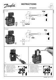
Connecting the room panel / remote control<br />
* Connect ECL terminal 9 to 1 and terminal 8 to 2.<br />
The ECA 60 / 61 / 62 / 63 is activated by the setting in line 7010.<br />
The ECA 60 / 61 / 62 / 63 is powered by the ECL BUS which means that the BUS must be active.<br />
The BUS is activated by setting the controller address to 15 (line 7199).<br />
44 VI.KT.G2.02 © <strong>Danfoss</strong> 05/2007 DH-SMT/DK<br />
If the temperature value is displayed as<br />
"- -" the sensor in question is not connected.<br />
"- - -" the sensor is short-circuited.<br />
Select control mode<br />
During scheduled operation (AUTO), the symbols will show you the control mode.<br />
<br />
<br />
Change the mode (AUTO, COMFORT, SETBACK, or STANDBY).<br />
Set your personal schedule<br />
It is only possible to set the personal schedules if the ECL Com<strong>for</strong>t 110 controller has a built-in<br />
ECA 110 timer program.<br />
<br />
<br />
This display will show the current day and time.<br />
Choose the day <strong>for</strong> which you wish to change the settings.<br />
DH-SMT/DK VI.KT.G2.02 © <strong>Danfoss</strong> 05/2007 9
Today’s schedule<br />
The first display will show you the start of the first com<strong>for</strong>t period (‘Start1’). See or<br />
change the start of this period.<br />
The first bar will blink.<br />
<br />
<br />
See or change the end (‘Stop1’) of the first com<strong>for</strong>t period.<br />
The next bar will blink.<br />
<br />
<br />
See or change the start (‘Start2’) of the next com<strong>for</strong>t period.<br />
<br />
<br />
See or change the next start / stop periods, if necessary.<br />
<br />
<br />
The schedule has always two com<strong>for</strong>t periods a day. The start and stop times can be set in<br />
half-hourly intervals (30 min.).<br />
10 VI.KT.G2.02 © <strong>Danfoss</strong> 05/2007 DH-SMT/DK<br />
Placing the temperature sensors<br />
It is important that the sensors are mounted in the correct position in your system.<br />
The temperature sensor mentioned below are sensors used <strong>for</strong> the ECL Com<strong>for</strong>t series<br />
which not all will be needed <strong>for</strong> your application!<br />
Outdoor temperature sensor (ESMT)<br />
The outdoor sensor should be mounted on that side of the building where it is less<br />
likely to be exposed to direct sunshine. It should not be placed close to doors, windows<br />
or air outlets.<br />
Flow temperature sensor (ESMU, ESM-11 or ESMC)<br />
Place the sensor max. 15 cm from the mixing point. In systems with heat exchanger,<br />
<strong>Danfoss</strong> recommends that the ESMU-type to be inserted into the exchanger flow outlet.<br />
Make sure that the surface of the pipe is clean and even where the sensor is mounted.<br />
Return temperature sensor (ESMU, ESM-11 or ESMC)<br />
The return sensor should always be placed in / on a pipe with return water flow.<br />
Room temperature sensor (ESM-10, ECA 60 / 62 room panel or ECA 61 / 63 remote<br />
control)<br />
Place the room sensor in the room where the temperature is to be controlled. Do not<br />
place it on outer walls or close to radiators, windows or doors.<br />
DHW temperature sensor (ESMU or ESMB-12)<br />
Place the DHW temperature sensor according to the manufacturer’s specification.<br />
Boiler temperature sensor (ESMU, ESM-11 or ESMC)<br />
Place the sensor according to the boiler manufacturer’s specification.<br />
Flow / air duct temperature sensor (ESM-11, ESMB-12, ESMC or ESMU types)<br />
Place the sensor so that it measures a representative temperature.<br />
Surface temperature sensor (ESMB-12)<br />
Place the sensor in the surface of the floor.<br />
Valid <strong>for</strong> ESM-11: Do not move the sensor after it has been fastened in order to avoid damage<br />
to the sensor element.<br />
DH-SMT/DK VI.KT.G2.02 © <strong>Danfoss</strong> 05/2007 43
Manual control<br />
Select control mode.<br />
<br />
<br />
5 sec.<br />
Go to manual mode.<br />
Actuator M1 is opening ( )<br />
<br />
Actuator M1 is closing ( ) <br />
Pump P1 is ON ( )<br />
<br />
Pump P1 is OFF ( ) <br />
Select control mode.<br />
<br />
<br />
Manual mode should only be used <strong>for</strong> maintenance purposes. In manual mode all control<br />
and safety functions are deactivated!<br />
42 VI.KT.G2.02 © <strong>Danfoss</strong> 05/2007 DH-SMT/DK<br />
Maintenance<br />
2 sec.<br />
Enter the maintenance menus.<br />
Date - time 1000<br />
It is only necessary to set the correct date and time in connection with the first use of the<br />
ECL Com<strong>for</strong>t 110 controller or after a power break of more than 36 hours (see the chapter<br />
on Adapting the ECL Com<strong>for</strong>t 110 controller).<br />
Flow temp. (flow temperature control) 2000<br />
Heat curve<br />
The ECL Com<strong>for</strong>t 110 controls the heating system according to the calculated flow<br />
temperature under the influence of the return and / or room temperature.<br />
The desired flow temperature is defined by 5 settings: ‘Temp. max.’, ‘Temp. min.’, ‘Slope’,<br />
‘Displace’, and ‘Knee point’.<br />
Desired flow temperature<br />
<br />
<br />
<br />
<br />
<br />
<br />
<br />
<br />
<br />
<br />
<br />
<br />
<br />
<br />
DH-SMT/DK VI.KT.G2.02 © <strong>Danfoss</strong> 05/2007 11<br />
<br />
Heat curve<br />
‘Slope’<br />
‘Temp. max.’<br />
‘Displace’<br />
‘Knee point’<br />
‘Temp. min.’<br />
Outdoor temp.<br />
The calculated flow temperature can be influenced by connected sensors, ‘Boost’ and ‘Ramp’<br />
etc.
Slope 2175<br />
Setting range Factory setting<br />
0.1 ... 4.0 1.8<br />
Adjust the ‘Slope’ of the heat curve, if required.<br />
The heat curve slope depends on the heating system and area specific design<br />
parameters.<br />
Example I<br />
Design parameter:<br />
Designed outdoor temperature (T out ) -12 °C<br />
Designed flow temperature (T flow ) 80 °C<br />
Designed room temperature (T room ) 20 °C<br />
For designed flow temperature higher than 40 °C, the heat curve slope (S) can be<br />
calculated as:<br />
S =<br />
S =<br />
S ≈ 1.7<br />
T flow - 25<br />
2.5 x T room - T out - 30<br />
80 - 25<br />
2.5 x 20 - (- 12) - 30<br />
Example II<br />
Design parameter:<br />
Designed outdoor temperature (T out ) -20 °C<br />
Designed flow temperature (T flow ) 35 °C<br />
Designed room temperature (T room ) 21 °C<br />
For designed flow temperatures lower than 40 °C, the heat curve slope (S) can be<br />
calculated as:<br />
S =<br />
S =<br />
S ≈ 0.3<br />
T flow - 20<br />
1.3 (2.5 x T room - T out - 30)<br />
35 - 20<br />
1.3 (2.5 x 21 - (- 20) - 30)<br />
For quick setting, the graph can be used. The graph is intended <strong>for</strong> a T room of 20 °C. If the<br />
design data from example I is used, the slope will be approx. 1.7.<br />
12 VI.KT.G2.02 © <strong>Danfoss</strong> 05/2007 DH-SMT/DK<br />
Adapting the ECL Com<strong>for</strong>t 110 controller<br />
When you switch on the controller the first time, it will ask you to choose language<br />
(default language is English).<br />
<br />
<br />
Choose your language.<br />
Accept and go to the next menu.<br />
When the language is chosen, the controller will ask <strong>for</strong> date and time setting.<br />
<br />
<br />
Set day (dd), month (mm), year (yy), hour (hh), and minuts (mm).<br />
Change values.<br />
Accept the chosen time and date.<br />
When the language has been chosen, and date and time have been set, the controller<br />
will ask <strong>for</strong> application type.<br />
<br />
<br />
Choose application type.<br />
2 sec.<br />
Start the chosen application.<br />
Go to the ‘Maintenance’ part <strong>for</strong> further setup of your controller.<br />
DH-SMT/DK VI.KT.G2.02 © <strong>Danfoss</strong> 05/2007 41
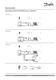
How to identify your system type<br />
The ECL Com<strong>for</strong>t controller is a universal controller that can be used <strong>for</strong> various systems.<br />
Based on the shown standard systems, it is possible to configure additional systems.<br />
In this section you find the most frequently used systems. If your system is not quite as<br />
shown below, find the diagram which has the best resemblance with your system and<br />
make your own combinations.<br />
<strong>Heating</strong> system 1:<br />
District heating circuit with heat exchanger<br />
<strong>Heating</strong> system 2:<br />
Boiler-based heating circuit<br />
40 VI.KT.G2.02 © <strong>Danfoss</strong> 05/2007 DH-SMT/DK<br />
[oC]<br />
150<br />
140<br />
1.8<br />
130<br />
120<br />
110 1.4<br />
100<br />
90<br />
80<br />
70<br />
60<br />
30<br />
20<br />
1.0<br />
0.6<br />
50 0.4<br />
0.3<br />
40<br />
0.2<br />
0.1<br />
2.2 2.6 3.0 3.5 4.0<br />
10<br />
-40 -30 -20 -10 0 10 20 30 [oC]<br />
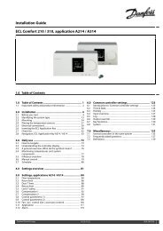
How to determine another heat curve, if necessary:<br />
Choose the calculated flow temperature <strong>for</strong> your system and the determined min.<br />
outdoor temperature <strong>for</strong> your area. Pick the heat curve closest to the crossing point of<br />
these two values.<br />
The setting of the desired room temperature has an influence on the calculated flow<br />
temperature (heat curve), no matter if a room temperature sensor is connected or not.<br />
Floor heating systems<br />
This controller is factory set <strong>for</strong> radiator systems, which typically are high flow temperature<br />
systems. To control floor heating systems, which typically are low flow temperature systems,<br />
you need to change the ‘Slope’ according to your type of system (typical setting: 1.0).<br />
DH-SMT/DK VI.KT.G2.02 © <strong>Danfoss</strong> 05/2007 13
Displace (parallel displacement) 2176<br />
Setting range Factory setting<br />
-20 ... 20 0<br />
Adjust the parallel displacement of the heat curve with a number of degrees, if required.<br />
Whether it is reasonable to change the ‘Slope’ (at outdoor temperatures below 0 °C) or<br />
parallel displacement (at outdoor temperatures above 0 °C) will depend on the individual<br />
heat requirement.<br />
Small increases or reductions in the heating temperature can be implemented by means of<br />
the parallel displacement.<br />
Temp. min. (flow temp. limit, min.) 2177<br />
Setting range Factory setting<br />
10 ... 150 °C 10 °C<br />
Choose the allowed min. flow temperature <strong>for</strong> your system. Adjust the factory setting, if<br />
required.<br />
Temp. max. (flow temp. limit, max.) 2178<br />
Setting range Factory setting<br />
10 ... 150 °C 90 °C<br />
Choose the allowed max. flow temperature <strong>for</strong> your system. Adjust the factory setting, if<br />
required.<br />
The setting <strong>for</strong> ‘Temp. max.’ has higher priority than ‘Temp. min.’.<br />
14 VI.KT.G2.02 © <strong>Danfoss</strong> 05/2007 DH-SMT/DK<br />
Connecting the temperature sensors and the ECL BUS<br />
Terminal Description Type (recomm.)<br />
1 and 2 S1 Outdoor temperature sensor ESMT<br />
3 and 4 S3 Flow temperature sensor ESM-11 / ESMC / ESMU<br />
5 and 6 S4 Return temperature sensor ESM-11 / ESMC / ESMU<br />
7 and 8 S2 Room temperature sensor ESM-10<br />
8 and 9 ECL BUS, connections <strong>for</strong> room panel /<br />
remote control<br />
10 Not to be used<br />
11 and 12 Ext. override<br />
Wire cross section <strong>for</strong> sensor connections:<br />
0.4 - 0.75 mm 2<br />
Total cable length: Max. 125 m (all sensors incl. the ECL BUS)<br />
Cable lengths of more than 125 m may cause noise sensibility (EMC).<br />
ECA 60 / 62<br />
ECA 61 / 63<br />
DH-SMT/DK VI.KT.G2.02 © <strong>Danfoss</strong> 05/2007 39
Electrical connections - 24 V a.c. - in general Room T limit (room temperature limitation) 3000<br />
* Optional connections <strong>for</strong> safety thermostat<br />
Terminal Description Max.<br />
load<br />
20 Supply voltage 24 V a.c. - A1<br />
21 Supply voltage 24 V a.c. - A2<br />
22 Optional connections <strong>for</strong> safety thermostat<br />
23 Optional connections <strong>for</strong> safety thermostat<br />
24 M1 Actuator - open, alt. thermo actuator (ABV) 15 VA<br />
25 M1 Actuator - close 15 VA<br />
26 M1 Actuator - A1<br />
27 Not to be used<br />
28 Not to be used<br />
29 P1 Phase <strong>for</strong> circulation pump (relay R2)<br />
30 P1 Relay R2 4 (2) A<br />
Wire cross section: 0.5 - 1.5 mm 2<br />
Incorrect connection can damage the TRIAC outputs.<br />
38 VI.KT.G2.02 © <strong>Danfoss</strong> 05/2007 DH-SMT/DK<br />
This section is only relevant if you have installed a room temperature sensor or room<br />
panel / remote control.<br />
The controller adjusts the desired flow temperature to eliminate the difference between<br />
the desired and the actual room temperature.<br />
There are two basic principles <strong>for</strong> control of the room temperature.<br />
A: Max. room temperature limitation<br />
Use this limitation if your heating system is fully equipped with thermostats and you also<br />
want to obtain a max. limitation of the room temperature. The controller will allow <strong>for</strong><br />
free heat gains, i.e. solar radiation or heat from a fire place, etc.<br />
Influence<br />
‘Gain - min.’ (min. limitation)<br />
Desired room temperature<br />
Actual room temperature<br />
‘Gain - max.’ (max. limitation)<br />
The ‘Gain - max.’ determines how much the room temperature should influence the<br />
desired flow temperature.<br />
If the ‘Gain’ is too high and / or the ‘Intgr. time’ too low, there is a risk of unstable control.<br />
Example A1<br />
The actual room temperature is 2 degrees too high.<br />
The ‘Gain - max.’ is set to -4.0.<br />
The ‘Gain - min.’ is set to 0.0.<br />
The ‘Slope’ is 1.8.<br />
Result:<br />
The desired flow temperature is changed by 2 x -4.0 x 1.8 = -14.4 degrees.<br />
DH-SMT/DK VI.KT.G2.02 © <strong>Danfoss</strong> 05/2007 15
B: Reference room temperature control<br />
Used if your heating system is not equipped with thermostats and you select the room<br />
with room temperature sensor as a temperature reference <strong>for</strong> the rest of the rooms.<br />
Set a positive value <strong>for</strong> the ‘Gain - min.’ and a negative value <strong>for</strong> the ‘Gain - max.’.<br />
Influence<br />
‘Gain - min.’ (min. limitation)<br />
Desired room temperature<br />
Actual room temperature<br />
‘Gain - max.’ (max. limitation)<br />
The room temperature sensor in the reference room measures the actual room<br />
temperature.<br />
If a difference occours between the actual and the desired room temperature, the<br />
desired flow temperature can be corrected. The correction is based on the settings in<br />
the lines 3182 and 3183. This correction of the desired flow temperature will normally<br />
give a correct room temperature. See also line 3015.<br />
Example B1<br />
The actual room temperature is 2 degrees too low.<br />
The ‘Gain - max.’ is set to -3.5.<br />
The ‘Gain - min.’ is set to 2.0.<br />
The ‘Slope’ is 1.8.<br />
Result:<br />
The desired flow temperature is changed by 2 x 2.0 x 1.8 = 7.2 degrees.<br />
Example B2<br />
The actual room temperature is 2 degrees too high.<br />
The ‘Gain - max.’ is set to -3.5.<br />
The ‘Gain - min.’ is set to 2.0.<br />
The ‘Slope’ is 1.8.<br />
Result:<br />
The desired flow temperature is changed by 2 x (-3.5) x 1.8 = -12.6 degrees.<br />
16 VI.KT.G2.02 © <strong>Danfoss</strong> 05/2007 DH-SMT/DK<br />
Electrical connections - 230 V a.c. - in general<br />
* Optional connections <strong>for</strong> safety thermostat<br />
Terminal Description Max.<br />
load<br />
20 Supply voltage 230 V a.c. - neutral (N)<br />
21 Supply voltage 230 V a.c. - live (L)<br />
22 Optional connections <strong>for</strong> safety thermostat<br />
23 Optional connections <strong>for</strong> safety thermostat<br />
24 M1 Actuator - open, alt. thermo actuator (ABV) 15 VA<br />
25 M1 Actuator - close 15 VA<br />
26 M1 Actuator - neutral<br />
27 P1 Circulation pump - neutral<br />
28 P1 Circulation pump - live (relay R1) 4 (2) A<br />
29 Not to be used<br />
30 Not to be used<br />
Wire cross section: 0.5 - 1.5 mm 2<br />
Incorrect connection can damage the TRIAC outputs.<br />
DH-SMT/DK VI.KT.G2.02 © <strong>Danfoss</strong> 05/2007 37
Installation<br />
Mounting the ECL Com<strong>for</strong>t controller<br />
For easy access, you should mount the ECL Com<strong>for</strong>t controller near the system. Select<br />
one of the three following methods:<br />
• Mounting on a wall<br />
• Mounting on a DIN rail<br />
• Mounting in a panel<br />
Screws and rawlplugs are not supplied.<br />
Mounting on a wall<br />
Mount the controller on a wall with a smooth surface and establish the electrical<br />
connections.<br />
Mounting on a DIN rail<br />
Mount the controller on the DIN rail and establish the electrical connections.<br />
Mounting in a panel<br />
Mounting kit: Order code no. 087B1249.<br />
The panel plate thickness must not exceed 5 mm. Prepare a cut-out with the dimensions<br />
93 x 139 mm. Insert the controller into the panel cut-out and fix it with the clamp which<br />
is placed horisontally on the controller. Establish the electrical connections.<br />
For further details on mounting, see the mounting guide.<br />
36 VI.KT.G2.02 © <strong>Danfoss</strong> 05/2007 DH-SMT/DK<br />
<strong>Danfoss</strong><br />
87B787.10<br />
<strong>Danfoss</strong><br />
87B788.10<br />
<strong>Danfoss</strong><br />
87B789.10<br />
This limitation is based on a PI regulation where P (Gain) responds quickly to deviations<br />
and I (Intgr. time) responds slower and over time removes the small offsets between the<br />
desired and actual values. This is done by changing the desired flow temperature.<br />
Intgr. time (time constant <strong>for</strong> room temp.) 3015<br />
Setting range Factory setting<br />
OFF / 1 ... 50 OFF<br />
Controls how fast the room temperature adapts to the desired room temperature (I control).<br />
OFF: The control function is not influenced by the ‘Intgr. time’.<br />
1: The desired temperature is adapted quickly.<br />
50: The desired temperature is adapted slowly.<br />
Gain - max. (room temp. limitation, max.) 3182<br />
Setting range Factory setting<br />
-9.9 ... 0.0 -4.0<br />
Determines how much the flow temperature will be influenced (decreased) if the room temperature is<br />
higher than the desired room temperature (P control).<br />
-9.9: The room temperature has a big influence.<br />
0.0: The room temperature has no influence.<br />
Gain - min. (room temp. limitation, min.) 3183<br />
Setting range Factory setting<br />
0.0 ... 9.9 0.0<br />
Determines how much the flow temperature will be influenced (increased) if the room temperature is<br />
lower than the desired room temperature (P control).<br />
0.0: The room temperature has no influence.<br />
9.9: The room temperature has a big influence.<br />
DH-SMT/DK VI.KT.G2.02 © <strong>Danfoss</strong> 05/2007 17
Return T limit (return temp. limitation) 4000<br />
The controller automatically changes the desired flow temperature to obtain an<br />
acceptable return temperature when the return temperature falls below or gets higher<br />
than the set limit.<br />
Influence<br />
‘Gain - min.’ > 0<br />
‘Limit’<br />
‘Gain max.’ > 0<br />
Return temperature<br />
‘Gain - max.’ < 0<br />
‘Gain - min.’ < 0<br />
This limitation is based on a PI regulation where P (Gain) responds quickly to deviations<br />
and I (Intgr. time) responds slower and over time removes the small offsets between the<br />
desired and actual values. This is done by changing the desired flow temperature.<br />
If the ‘Gain’ is too high and / or the ‘Intgr. time’ too low, there is a risk of unstable control.<br />
Limit (return temp. limitation) 4030<br />
Setting range Factory setting<br />
10 ... 110 °C 50 °C<br />
Set the return temperature you accept <strong>for</strong> the system.<br />
Set the acceptable return temperature limit.<br />
When the return temperature falls below or gets higher than the set value, the controller<br />
automatically changes the desired flow temperature to obtain an acceptable return<br />
temperature. The influence is set in lines 4035 and 4036.<br />
18 VI.KT.G2.02 © <strong>Danfoss</strong> 05/2007 DH-SMT/DK<br />
Language 8315<br />
Setting range Factory setting<br />
Multiple English<br />
Choose your language.<br />
MOD address (MODBUS address) 8320<br />
Setting range Factory setting<br />
0 ... 247 0<br />
Set the MODBUS address if the controller is part of a MODBUS network.<br />
Assign the MODBUS addresses within the stated setting range.<br />
DH-SMT/DK VI.KT.G2.02 © <strong>Danfoss</strong> 05/2007 35
Service 8000<br />
Code no. 8300<br />
Display<br />
087BXXXX<br />
Ver. (version no.) 8301<br />
Display<br />
ABBBCCWWYY<br />
A = Hardware version<br />
BBB = Software version<br />
CC = Application version<br />
WW = Production week<br />
YY = Production year<br />
Please state the version in connection with questions about the product, if any.<br />
Backlight (display brightness) 8310<br />
Setting range Factory setting<br />
OFF / 1 ... 30 16<br />
The brightness of the display can be adjusted.<br />
OFF: No backlight.<br />
1: Weak backlight.<br />
30: Strong backlight.<br />
Contrast (display contrast) 8311<br />
Setting range Factory setting<br />
0 ... 20 10<br />
The contrast of the display can be adjusted.<br />
0: High contrast<br />
20: Low contrast<br />
34 VI.KT.G2.02 © <strong>Danfoss</strong> 05/2007 DH-SMT/DK<br />
Gain - max. (return temp. limitation - max. influence) 4035<br />
Setting range Factory setting<br />
-9.9 ... 9.9 -2.0<br />
Determines how much the flow temperature will be influenced if the return temperature is higher than<br />
the desired ‘Limit’ (line 4030) (P control).<br />
Influence higher than 0:<br />
The desired flow temperature is increased, when the return temperature gets higher<br />
than the set limit.<br />
Influence lower than 0:<br />
The desired flow temperature is decreased, when the return temperature gets higher<br />
than the set limit.<br />
Example<br />
The return limit is active above 50 °C.<br />
The influence is set to -2.0.<br />
The actual return temperature is 2 degrees too high.<br />
Result:<br />
The desired flow temperature is changed by -2.0 x 2 = -4.0 degrees.<br />
Normally, the setting in line 4035 is lower than 0 in district heating systems to avoid a too<br />
high return temperature.<br />
Typically, the setting in line 4035 is 0 in boiler systems because a higher return temperature<br />
is acceptable (see also line 4036).<br />
Gain - min. (return temp. limitation - min. influence) 4036<br />
Setting range Factory setting<br />
-9.9 ... 9.9 0.0<br />
Determines how much the flow temperature will be influenced if the return temperature is lower than<br />
the desired ‘Limit’ (line 4030) (P control).<br />
Influence higher than 0:<br />
The desired flow temperature is increased, when the return temperature gets below the<br />
set limit.<br />
Influence lower than 0:<br />
The desired flow temperature is decreased, when the return temperature gets below the<br />
set limit.<br />
DH-SMT/DK VI.KT.G2.02 © <strong>Danfoss</strong> 05/2007 19
Example<br />
The return limit is active below 50 °C.<br />
The influence is set to -3.0.<br />
The actual return temperature is 2 degrees too low.<br />
Result:<br />
The desired flow temperature is changed by -3.0 x 2 = -6.0 degrees.<br />
Normally, the setting in line 4036 is 0 in district heating systems because a lower return<br />
temperature is acceptable.<br />
Typically, the setting in line 4036 is higher than 0 in boiler systems to avoid a too low return<br />
temperature (see also line 4035).<br />
Intgr. time (time constant <strong>for</strong> return temp. limitation) 4037<br />
Setting range Factory setting<br />
OFF / 1 ... 50 25 sec.<br />
Controls how fast the return temperature adapts to the desired return temperature (I control).<br />
OFF: The control function is not influenced by the ‘Intgr. time’.<br />
1: The desired temperature is adapted quickly.<br />
50: The desired temperature is adapted slowly.<br />
Priority (priority <strong>for</strong> return temp. limitation) 4085<br />
Setting range Factory setting<br />
ON / OFF OFF<br />
Choose whether the return temperature limitation should overrule the set min. flow temperature<br />
‘Temp. min.’ (line 2177).<br />
ON: The min. flow temperature limit is overruled.<br />
OFF: The min. flow temperature limit is not overruled.<br />
20 VI.KT.G2.02 © <strong>Danfoss</strong> 05/2007 DH-SMT/DK<br />
ECL address (master / slave address) 7199<br />
Setting range Factory setting<br />
0 ... 15 15<br />
This settting is relevant if more controllers are working in the same ECL Com<strong>for</strong>t system (connected via<br />
the ECL BUS) and / or ECA units are connected.<br />
0: The controller works as slave. The slave receives in<strong>for</strong>mation about the<br />
outdoor temperature (S1), system time, and signal <strong>for</strong> DHW demand in<br />
the master.<br />
1 ... 9: The controller works as slave. The slave receives in<strong>for</strong>mation about the<br />
outdoor temperature (S1), system time, and signal <strong>for</strong> DHW demand<br />
in the master. The slave sends in<strong>for</strong>mation about the desired flow<br />
temperature to the master.<br />
10 ... 14:<br />
Not used.<br />
15: The controller is master. The master sends in<strong>for</strong>mation about the outdoor<br />
temperature (S1) and system time. The ECL BUS is active and connected<br />
ECAs are powered.<br />
The ECL Com<strong>for</strong>t controllers can be connected via the ECL BUS to per<strong>for</strong>m a larger<br />
system. The controller, which is physically connected with the outdoor temperature<br />
sensor, is the master of the entire system and must have the address 15.<br />
Each slave must be configured with its own address (1 ... 9).<br />
However, more slaves can have the address 0 if they only have to receive in<strong>for</strong>mation<br />
about outdoor temperature and system time.<br />
Type 7600<br />
Setting range Factory setting<br />
116 / 130 130<br />
Use this setting to change your application or restore the factory settings.<br />
116: Constant temperature control of DHW circuit.<br />
130: Weather compensated control of heating and boiler systems.<br />
5 sec.<br />
Start the chosen application.<br />
Factory settings are restored. All personal settings will be deleted. It is recommended to<br />
make a note of your personal settings in the ‘Settings overview’ <strong>for</strong> future use.<br />
DH-SMT/DK VI.KT.G2.02 © <strong>Danfoss</strong> 05/2007 33
Knee point 7162<br />
Setting range Factory setting<br />
OFF / 30 ... 50 °C 40 °C<br />
Choose the temperature at which the heat curve should bend.<br />
OFF: Floor heating systems.<br />
30 ... 50:<br />
Radiator systems.<br />
Min. on time (min. activation time gear motor) 7189<br />
Setting range Factory setting<br />
2 ... 50 10<br />
The min. pulse length in milliseconds <strong>for</strong> activation of the gear motor.<br />
Setting Value x 20 ms<br />
2 40 ms<br />
10 200 ms<br />
50 1000 ms<br />
The setting should be kept as high as acceptable to increase the lifetime of the actuator.<br />
Daylight (daylight saving time changeover) 7198<br />
Setting range Factory setting<br />
ON / OFF ON<br />
Choose whether you want the change to summer / winter time to be automatic or manual.<br />
ON: The controller’s built-in clock automatically changes + / - one hour on<br />
the standardized days <strong>for</strong> daylight saving time changeover <strong>for</strong> Central<br />
Europe.<br />
OFF: You change manually between summer and winter time by setting the<br />
clock backward or <strong>for</strong>ward.<br />
32 VI.KT.G2.02 © <strong>Danfoss</strong> 05/2007 DH-SMT/DK<br />
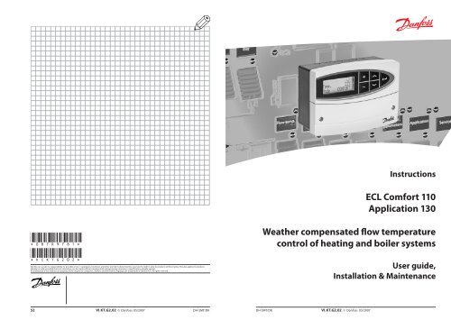
Optimize 5000<br />
Auto-reduct (setback temp. dependent on outdoor temp.) 5011<br />
Setting range Factory setting<br />
OFF / -29 ... 10 °C -15 °C<br />
Below this outdoor temperature, the setback temperature setting has no influence.<br />
-29 ... 10:<br />
The setback temperature depends on the outdoor temperature, when<br />
the outdoor temperature is above the set limit. The lower the outdoor<br />
temperature, the less the temperature reduction. When the outdoor<br />
temperature is below the set limit, there is no temperature reduction.<br />
OFF: The setback temperature does not depend on the outdoor temperature.<br />
Reduction<br />
100%<br />
0%<br />
-29 -20 -10 0 10 20<br />
Setting line 5011<br />
Outdoor<br />
temp. °C<br />
Boost 5012<br />
Setting range Factory setting<br />
OFF / 1 ... 99% OFF<br />
Shortens the heating-up period by increasing the desired flow temperature by the percentage you set.<br />
Set the percentage at which you want the desired flow temperature increased<br />
temporarily.<br />
In order to shorten the heating-up period after a setback temperature period, the<br />
desired flow temperature can be increased temporarily (max. 1 hour). At optimizing the<br />
boost is active in the optimization period (line 5014).<br />
If a room temperature sensor or a room panel / remote control is connected, the boost<br />
stops when the room temperature is reached.<br />
DH-SMT/DK VI.KT.G2.02 © <strong>Danfoss</strong> 05/2007 21
Ramp (reference ramping) 5013<br />
Setting range Factory setting<br />
OFF / 1 ... 99 min. OFF<br />
The time in which the desired flow temperature increases gradually to avoid load peaks in the heat<br />
supply.<br />
Set the ramping time <strong>for</strong> the controller.<br />
Temp. °C<br />
Setting line 5013<br />
Time (min.)<br />
In order to avoid load peaks in the supply network, the flow temperature can be set<br />
to increase gradually after a period with setback temperature. This causes the valve to<br />
open gradually.<br />
Optimizer (optimizing time constant) 5014<br />
Setting range Factory setting<br />
OFF / 10 ... 59 OFF<br />
Optimizes the start and stop times <strong>for</strong> the com<strong>for</strong>t temperature period to obtain the best com<strong>for</strong>t at<br />
the lowest energy consumption. The lower the outdoor temperature, the earlier the heating cut-in.<br />
Adjust the optimizing time constant.<br />
The value consists of a two digit number. The two digits have the following meaning:<br />
Left digit Heat accumulation of the building System type<br />
1X light<br />
2X medium<br />
Radiator systems<br />
3X heavy<br />
4X<br />
5X<br />
medium<br />
heavy<br />
Floor heating systems<br />
22 VI.KT.G2.02 © <strong>Danfoss</strong> 05/2007 DH-SMT/DK<br />
P1 heat T (heat demand) 7078<br />
Setting range Factory setting<br />
5 ... 40 °C 20 °C<br />
When the desired flow temperature is above the set temperature in ‘P1 heat T’, the controller<br />
automatically switches ON the circulation pump to meet the heat demand.<br />
5 ... 40:<br />
The circulation pump is ON above the set value.<br />
The valve is fully closed as long as the pump is not switched on.<br />
Standby T (standby temperature) 7093<br />
Setting range Factory setting<br />
5 ... 40 °C 10 °C<br />
Set the desired flow temperature at standby (e.g. during total stop).<br />
5 ... 40:<br />
Desired standby flow temperature.<br />
Ext. (external override) 7141<br />
Setting range Factory setting<br />
OFF / SETBACK / COMFORT OFF<br />
Choose mode <strong>for</strong> ‘Ext.’ (external override).<br />
The override can be activated <strong>for</strong> setback or com<strong>for</strong>t mode. For override, the controller<br />
mode must be AUTO (scheduled operation).<br />
OFF: The controller's schedule is not overridden.<br />
SETBACK:<br />
The controller is in setback mode when terminals 11 and 12 are shortcircuited.<br />
COMFORT:<br />
The controller is in com<strong>for</strong>t mode when terminals 11 and 12 are shortcircuited.<br />
DH-SMT/DK VI.KT.G2.02 © <strong>Danfoss</strong> 05/2007 31
DHW prior. (closed valve / normal operation) 7052<br />
Setting range Factory setting<br />
ON / OFF OFF<br />
The heating circuit can be closed when the controller acts as slave and when DHW charging is active in<br />
the master.<br />
ON: The valve in the heating circuit is closed* during active DHW charging in<br />
the master controller.<br />
* The desired flow temperature is set to ‘Standby T’ (line 7093)<br />
OFF: The flow temperature control remains unchanged during active DHW<br />
charging in the master controller.<br />
The setting in line 7052 must be considered if this controller is a slave.<br />
P1 frost T (frost protection) 7077<br />
Setting range Factory setting<br />
OFF / -10 ... 20 °C 2 °C<br />
When the outdoor temperature is below the set temperature in ‘P1 frost T’, the controller automatically<br />
switches ON the circulation pump to protect the system.<br />
OFF: No frost protection.<br />
-10 ... 20:<br />
The circulation pump is ON when the outdoor temperature is below<br />
the set value.<br />
Under normal conditions, your system is not frost protected if your setting is below 0 °C or<br />
OFF. For water-based systems, a setting of 2 °C is recommended.<br />
30 VI.KT.G2.02 © <strong>Danfoss</strong> 05/2007 DH-SMT/DK<br />
Right digit Dimensioning temperature Capacity<br />
X0 -50 °C large<br />
X1 -45 °C •<br />
• • •<br />
X5 -25 °C normal<br />
• • •<br />
X9 -5 °C small<br />
OFF: No optimization. The heating starts and stops at the times set in the<br />
schedule.<br />
Dimensioning temperature:<br />
The lowest outdoor temperature (usually determined by your system designer in<br />
connection with the design of the heating system) at which the heating system can<br />
maintain the designed room temperature.<br />
Example<br />
The system type is radiator, and the heat accumulation of the building is medium.<br />
The left digit is 2.<br />
The dimensioning temperature is -25 °C, and the capacity is normal.<br />
The right digit is 5.<br />
Result:<br />
The setting is to be changed to 25.<br />
It is only possible make use of ‘Optimize’ if the ECL Com<strong>for</strong>t 110 controller has a built-in ECA<br />
110 timer program or is connected to an ECA 61 / 63.<br />
Based on (optimization based on room / outdoor temp.) 5020<br />
Setting range Factory setting<br />
ROOM / OUT OUT<br />
The optimized start and stop time can be based on either room or outdoor temperature.<br />
ROOM: Optimization based on room temperature, if measured.<br />
OUT: Optimization based on outdoor temperature. Use this setting if the<br />
room temperature is not measured.<br />
DH-SMT/DK VI.KT.G2.02 © <strong>Danfoss</strong> 05/2007 23
Total stop 5021<br />
Setting range Factory setting<br />
ON / OFF OFF<br />
Decide whether you want a total stop during the setback temperature period.<br />
ON: The desired system temperature is lowered to ‘Standby T’ (line 7093).<br />
‘Temp. min.’ (line 2177) is overruled.<br />
Desired system temp. °C<br />
‘Standby T’<br />
OFF: No total stop<br />
Desired system temp. °C<br />
‘Standby T’<br />
S1 T filter (outdoor temp. filter) 5081<br />
Setting range Factory setting<br />
1 ... 200 100<br />
Dampens the measured outdoor temperatures by the set factor.<br />
1: Fast (low filter constant)<br />
200: Slow (high filter constant)<br />
24 VI.KT.G2.02 © <strong>Danfoss</strong> 05/2007 DH-SMT/DK<br />
Time<br />
Time<br />
Application 7000<br />
ECA address (choice of room panel / remote control) 7010<br />
Setting range Factory setting<br />
OFF / A / B OFF<br />
Decides the communication with the room panel or remote control.<br />
OFF: Room temperature sensor (no room panel / remote control)<br />
A: Room panel ECA 60 / 62 or remote control, ECA 61 / 63 with address A<br />
B: Room panel ECA 60 / 62 or remote control, ECA 61 / 63 with address B<br />
P1 exercise (pump exercise) 7022<br />
Setting range Factory setting<br />
ON / OFF ON<br />
Exercises the pump to avoid blocking in periods without heat demand.<br />
ON: The pump is switched ON <strong>for</strong> 1 minute every third day around noon.<br />
OFF: The pump exercise is not active.<br />
M1 exercise (valve exercise) 7023<br />
Setting range Factory setting<br />
ON / OFF OFF<br />
Exercises the valve to avoid blocking in periods without heat demand.<br />
ON: The valve receives a signal to open and close every third day around<br />
noon.<br />
OFF: The valve exercise is not active.<br />
Actuator (gear motor / thermo actuator) 7024<br />
Setting range Factory setting<br />
GEAR / ABV GEAR<br />
Choose the actuator type <strong>for</strong> your valve.<br />
GEAR: Gear motor<br />
ABV: Thermo actuator (<strong>Danfoss</strong> type ABV)<br />
Control parameters (lines 6174-6187) are overruled if thermo actuator is chosen (ABV).<br />
DH-SMT/DK VI.KT.G2.02 © <strong>Danfoss</strong> 05/2007 29
If you want to tune the PI regulation precisely, you can use the following<br />
method:<br />
• Set the ‘Tn’ (integration time constant line 6185) to its max. value (999 sec.).<br />
• Decrease the value <strong>for</strong> the ‘Xp’ (proportional band line 6184) until the system starts<br />
hunting with a constant amplitude (it might be necessary to <strong>for</strong>ce the system by setting<br />
an extreme value).<br />
• Find the critical time period on the temperature recording or use a stop watch.<br />
Temp. Critical time period<br />
28 VI.KT.G2.02 © <strong>Danfoss</strong> 05/2007 DH-SMT/DK<br />
Time<br />
This time period will be characteristic <strong>for</strong> the system, and you can evaluate the settings from<br />
this critical period.<br />
‘Tn’ = 0.85 x critical time period<br />
‘Xp’ = 2.2 x proportional band value in the critical time period.<br />
If the regulation seems to be too slow, you can decrease the proportional band value by<br />
10%.<br />
Cut-out (limit <strong>for</strong> heating cut-out) 5179<br />
Setting range Factory setting<br />
OFF / 1 ... 50 °C 18 °C<br />
Set the outdoor temperature limit at which you want the heating system to stop. The<br />
valve closes and after about 3 min. the heating circulation pump stops. ‘Temp. min.’<br />
set in line 2177 will be ignored.<br />
18 °C<br />
Temp. Actual outdoor temp. Accumulated outdoor temp.<br />
<strong>Heating</strong> <strong>Heating</strong> OFF <strong>Heating</strong><br />
DH-SMT/DK VI.KT.G2.02 © <strong>Danfoss</strong> 05/2007 25<br />
Time<br />
This function can save energy by stopping the heating system when the outdoor<br />
temperature gets above a set limit. The heating system switches ON again when the<br />
outdoor temperature and the accumulated outdoor temperature become lower than<br />
the set limit.<br />
The heating cut-out is only active when the controller mode is AUTO (scheduled operation).<br />
When the limit value is set to OFF, there is no heating cut-out.
Control param. (control parameters) 6000<br />
Motor prot. (motor protection) 6174<br />
Setting range Factory setting<br />
OFF / 10 ... 59 min. OFF<br />
Prevents the controller from unstable temperature control (and resulting actuator oscillations). This<br />
can occur at very low load. The motor protection increases the lifetime of all involved components.<br />
OFF: Motor protection is not activated.<br />
10 ... 59:<br />
Motor protection is activated after the set activation delay.<br />
Typically used <strong>for</strong> DHW applications. Can also be used <strong>for</strong> heating systems at very low load.<br />
Xp (proportional band) 6184<br />
Setting range Factory setting<br />
1 ... 250 K 80 K<br />
Set the proportional band. A higher value will result in a stable but slow control of the<br />
flow temperature.<br />
Tn (integration time constant) 6185<br />
Setting range Factory setting<br />
5 ... 999 sec. 30 sec.<br />
Set a high integration time constant to obtain a slow but stable reaction to deviations.<br />
A low integration constant will make the controller react fast but with less stability.<br />
M1 run (running time of the motorized control valve) 6186<br />
Setting range Factory setting<br />
5 ... 250 sec. 35 sec.<br />
‘M1 run’ is the time it takes the controlled unit to move from fully closed to fully open<br />
position. Set the ‘M1 run’ according to the example.<br />
26 VI.KT.G2.02 © <strong>Danfoss</strong> 05/2007 DH-SMT/DK<br />
How to calculate the running time of a motorized control valve<br />
The running time of the motorized control valve is calculated using the following methods:<br />
Seated valves<br />
Running time = Valve stroke (mm) x actuator speed (sec. / mm)<br />
Example: 5.0 mm x 15 sec. / mm = 75 sec.<br />
Rotating valves<br />
Running time = Turning degrees x actuator speed (sec. / degr.)<br />
Example: 90 degr. x 2 sec. / degr. = 180 sec.<br />
Nz (neutral zone) 6187<br />
Setting range Factory setting<br />
1 ... 9 K 3 K<br />
Set the acceptable flow temperature deviation.<br />
Set the neutral zone to a high value if you can accept a high variation in flow<br />
temperature. When the actual flow temperature is within the neutral zone, the controller<br />
does not activate the motorized control valve.<br />
The neutral zone is symmetrical around the desired flow temperature value, i.e. half the<br />
value is above and half the value is below this temperature.<br />
DH-SMT/DK VI.KT.G2.02 © <strong>Danfoss</strong> 05/2007 27