HTX-10 - The Gator Amateur Radio Club
HTX-10 - The Gator Amateur Radio Club
HTX-10 - The Gator Amateur Radio Club

Create successful ePaper yourself
Turn your PDF publications into a flip-book with our unique Google optimized e-Paper software.
Cat. No. 19-11<strong>10</strong> A<br />
OWNER’S MANUAL<br />
Please read before using this equipment.<br />
<strong>HTX</strong>-<strong>10</strong><br />
<strong>10</strong>-Meter Transceiver
FEATURES<br />
Your <strong>Radio</strong>Shack <strong>HTX</strong>-<strong>10</strong> <strong>10</strong>-Meter Transceiver is ideal for use<br />
in your vehicle. Its 25-watt SSB/FM and 7-watt AM output provides<br />
the power you need to communicate, and its tuner covers<br />
the entire <strong>10</strong>-meter <strong>Amateur</strong> <strong>Radio</strong> band (including the 28.3 to<br />
28.5 MHz Novice band). You can connect a DC power supply and<br />
base station antenna to your transceiver to set up a base station<br />
in your home. <strong>The</strong> transceiver’s crystal-controlled circuitry provides<br />
accurate and stable channel selection, making it an ideal<br />
choice for your amateur communications needs.<br />
Your transceiver has these advanced features:<br />
Large, Illuminated, Digital Display — clearly shows the frequency,<br />
functions, and incoming signal strength.<br />
1 kHz Frequency Resolution — lets you fine tune frequencies<br />
for optimum transmission and reception.<br />
Scan — the transceiver scans its frequency range for transmissions.<br />
MIC and RF Gain Control — lets you adjust the microphone and<br />
receiver gain to match the strength of the received signal.<br />
Switchable Noise Blanker — reduces interference from ignition<br />
systems, motors, and other electrical equipment.<br />
Squelch Circuit — compensates for signal fading and eliminates<br />
signal chopping.<br />
Automatic Gain Control — maintains a constant volume level,<br />
regardless of the signal strength.<br />
Built-In Automatic Modulation Control — ensures a constant<br />
RF modulation level.<br />
Universal Mounting Bracket — lets you mount your transceiver<br />
securely in your vehicle or on a shelf in your home.<br />
2<br />
© 2000 Tandy Corporation.<br />
All Rights Reserved.<br />
<strong>Radio</strong>Shack is a registered trademark used by Tandy Corporation.
Important: You must have a Technician Class or higher <strong>Amateur</strong><br />
<strong>Radio</strong> Operator’s License, and a call sign issued by the FCC, to<br />
legally transmit using this transceiver. Transmitting without a license<br />
carries heavy penalties. Getting a license is easier than ever.<br />
See “Introduction to <strong>Amateur</strong> <strong>Radio</strong>” on Page 6 for more<br />
information.<br />
We recommend you record your transceiver’s serial number<br />
here. <strong>The</strong> number is on the transceiver’s back panel.<br />
Serial Number ____________________________<br />
3
MANUAL CONVENTIONS<br />
Your transceiver’s buttons perform multiple functions. <strong>The</strong> abbreviation<br />
or symbol for a function is printed on, below, or above<br />
each button.<br />
To activate certain transceiver features, you must press PUSH<br />
FUNC (function) then another button.<br />
Button names are printed in this manual in small, bold, capital letters<br />
(such as PUSH FUNC or SCAN). Words, symbols, and numbers<br />
that appear on the display are printed using a distinctive<br />
typeface (such as 28.300 or BUSY).<br />
FCC INFORMATION<br />
This device complies with Part 15 of the FCC Rules. Operation is<br />
subject to the following two conditions: (1) This device may not<br />
cause harmful interference, and (2) this device must accept any<br />
interference received, including interference that may cause undesired<br />
operation.<br />
This equipment complies with the limits for a Class B digital device<br />
as specified in Part 15 of FCC Rules. <strong>The</strong>se limits provide<br />
reasonable protection against radio and TV interference in a residential<br />
area. However, your equipment might cause TV or radio<br />
interference even when it is operating properly. To eliminate interference,<br />
you can try one or more of the following corrective<br />
measures:<br />
• reorient or relocate the receiving antenna<br />
• increase the distance between the equipment and the radio<br />
or TV<br />
Consult your local <strong>Radio</strong>Shack store if the problem still exists.<br />
You must use shielded interface cables with this equipment.<br />
4
CONTENTS<br />
Introduction to <strong>Amateur</strong> <strong>Radio</strong> ............................................. 6<br />
Preparation ............................................................................. 8<br />
Attaching the Microphone Holder ..................................... 8<br />
Mounting the Transceiver ................................................. 8<br />
Connecting an Antenna .................................................. <strong>10</strong><br />
Connecting the Microphone ............................................ 12<br />
Connecting an Optional External Speaker ...................... 12<br />
Using Vehicle Battery Power .......................................... 13<br />
Using the Transceiver as a Base Station ........................ 14<br />
A Quick Look at the Controls ............................................. 16<br />
Operation .............................................................................. 17<br />
Setting Squelch and Receiving ....................................... 17<br />
Transmitting .................................................................... 18<br />
Notes on SSB Reception ................................................ 19<br />
Special Features .................................................................. 20<br />
Using the Special Features ............................................. 20<br />
Using STEP ............................................................. 21<br />
Using CALL ............................................................. 22<br />
Using SCAN ............................................................ 22<br />
Using LCR (Last Channel Recall) ............................ 23<br />
Using M-LOAD ........................................................ 23<br />
Using NB (Noise Blanker) ........................................ 23<br />
Using SHIFT ............................................................ 24<br />
Using T-LOW (Tone-Low) ........................................ 24<br />
Using M-SAVE (Memory Save) ............................... 25<br />
Using FINE (Clarifier) .............................................. 25<br />
Using RF-G (RF Gain) ............................................. 26<br />
Using MIC-G (Microphone Gain) ............................. 26<br />
Turning the Key Tone on and Off .................................... 26<br />
Care and Maintenance ......................................................... 27<br />
Troubleshooting ................................................................... 28<br />
Noise Reduction ............................................................. 29<br />
Replacing the Fuse ......................................................... 30<br />
Specifications ....................................................................... 32<br />
5
INTRODUCTION TO AMATEUR<br />
RADIO<br />
This transceiver is a great intermediate-level tool for the experienced<br />
amateur radio operator. <strong>The</strong> transceiver opens a door for<br />
you to the world from almost anywhere! All you need is an <strong>Amateur</strong><br />
<strong>Radio</strong> Operator’s License (Novice Class, or Technician Plus,<br />
or higher) issued by the Federal Communications Commission<br />
(FCC). If you do not have a license, it is easier than ever to get<br />
one and help from licensed operators is available. Here are a few<br />
tips to help you get started.<br />
You can turn on your transceiver and scan the entire band to hear<br />
what is going on; however, do not attempt to transmit until<br />
you get your license. If you transmit without a license, you are<br />
in violation of federal law. That violation can lead to severe penalties.<br />
Note that ham operators take the FCC rules very seriously<br />
and want nothing to do with “bootleggers” — their term for people<br />
who operate without a license.<br />
Find out if there is a ham radio club in your area. Most clubs welcome<br />
newcomers and are glad to help you get your license.<br />
<strong>The</strong>re are thousands of clubs across the country, so there is probably<br />
one in or near your own community. Often, the staff at your<br />
local <strong>Radio</strong>Shack store can help you locate a club.<br />
If you do not hear anyone talking about a local club in your area<br />
as you listen to local transmissions, write to the American <strong>Radio</strong><br />
Relay League (ARRL) at the following address, to find out how to<br />
contact a local affiliate. <strong>The</strong> ARRL is the national organization<br />
representing amateur radio in the United States. <strong>The</strong> league has<br />
more than 150,000 members. Most are ham operators, or members<br />
in the process of obtaining their license.<br />
6<br />
<strong>The</strong> American <strong>Radio</strong> Relay League<br />
225 Main Street<br />
Newington, CT 06111<br />
http://www.arrl.org
Start studying for the license exams. Do not be intimidated by the<br />
word “study,” for most people can go from knowing absolutely<br />
nothing about amateur radio to passing the Novice and Technician<br />
written exams in less than a month.<br />
<strong>The</strong> exams test your knowledge of basic radio regulations and elementary<br />
radio theory. Many clubs hold license classes, which<br />
can be a fun and easy way to learn about amateur radio. <strong>The</strong>re<br />
are good books, cassette tapes, computer programs, and many<br />
other study aids available. Your local <strong>Radio</strong>Shack store sells FCC<br />
License Preparation study guides for amateur radio operator licenses.<br />
While you are no longer required to learn Morse code for<br />
a Technician Class license, we encourage you to learn it anyway<br />
so you can advance to higher levels of operating privileges.<br />
<strong>The</strong> examiners for a Novice license test can be any two ham operators<br />
who hold a general or higher class license and who are at<br />
least 18 years old and are not related to you. <strong>The</strong>re is no fee to<br />
take the Novice exam. As soon as you pass the Novice exam,<br />
you can immediately take the Technician exam. <strong>The</strong>re is a small<br />
fee required for taking the Technician exam, and the test must be<br />
administered by a three-member Volunteer Examiner Team.<br />
Contact the ARRL for a schedule of exam opportunities in your<br />
area.<br />
A Novice Class or Technician Plus (or higher) license lets you use<br />
the <strong>HTX</strong>-<strong>10</strong> to communicate directly with other operators.<br />
<strong>Amateur</strong> radio is a great hobby that has enriched the lives of millions<br />
of people all over the world. <strong>The</strong> ARRL would be glad to hear<br />
from you if you need more information or would like to join!<br />
7
PREPARATION<br />
ATTACHING THE MICROPHONE<br />
HOLDER<br />
You can connect the microphone holder horizontally or vertically<br />
to either side of the transceiver or to another location in your vehicle.<br />
Use the supplied screws and lock washers to secure the holder<br />
to the side of the transceiver.<br />
Or, follow these steps to attach the holder to another location in<br />
the vehicle (such as the dashboard).<br />
1. Using the holder as a template, mark the positions for the<br />
mounting screw holes at the desired location.<br />
2. At each marked position, drill a hole slightly smaller than the<br />
supplied mounting screws.<br />
Caution: Be careful not to drill into anything behind the<br />
mounting surface.<br />
3. Attach the holder at the mounting location using the supplied<br />
machine screws and lock washers.<br />
MOUNTING THE TRANSCEIVER<br />
<strong>The</strong> most common mounting location for this transceiver is under<br />
a vehicle's dashboard. If you use the <strong>HTX</strong>-<strong>10</strong> as a base station,<br />
however, you can place it on a desk, shelf, or table (see “Using<br />
the Transceiver as a Base Station” on Page 14).<br />
8
If you are mounting the transceiver in a vehicle, choose a location<br />
where:<br />
• you can easily reach the transceiver.<br />
• wires and cables are clear of the vehicle's pedals or other<br />
moving parts.<br />
• the transceiver is not directly in front of heating vents.<br />
• all wires and cables can reach their connection points.<br />
Warning: If you use the transceiver in a vehicle, mount it securely<br />
to avoid damage to the transceiver or vehicle, and to avoid injury<br />
to anyone in the vehicle during sudden starts or stops.<br />
Follow these steps to mount the transceiver using the supplied<br />
hardware.<br />
1. Using the mounting bracket as a template, mark the positions<br />
for the screw holes on the mounting surface.<br />
2. In each marked location, drill a hole slightly smaller than the<br />
supplied mounting screws.<br />
Caution: Be careful not to drill into objects behind the<br />
mounting surface.<br />
3. Using a Phillips screwdriver, attach the mounting bracket to<br />
the mounting surface with the supplied mounting screws<br />
and flat washers.<br />
9
<strong>10</strong><br />
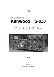
4. Attach the transceiver to the mounting bracket using the<br />
supplied rubber washers and mounting knobs.<br />
CONNECTING AN ANTENNA<br />
(Rubber washers<br />
not shown)<br />
<strong>The</strong>re are many different types of transceiver antennas for mobile<br />
transceivers. Each antenna type has its own benefits, so choose<br />
the one that best meets your needs. Your local <strong>Radio</strong>Shack store<br />
sells a wide variety of antennas.<br />
Note: If you are using this transceiver as a base station, see “Using<br />
the Transceiver as a Base Station” on Page 14.<br />
When you choose an antenna, keep in mind that for the best<br />
performance you should mount the antenna:<br />
• as high as possible on the vehicle<br />
• as far as possible from sources of electrical noise<br />
• vertically
Once you choose an antenna, follow<br />
its mounting instructions. <strong>The</strong>n route<br />
the cable to the transceiver and connect<br />
the cable to the ANT jack on the<br />
back of the transceiver.<br />
Cautions:<br />
• Avoid routing the cable next to<br />
sharp edges or moving parts,<br />
which might damage the cable.<br />
• Do not run the cable next to<br />
power cables or other radio<br />
antenna cables.<br />
• Do not run the cable through the engine compartment or<br />
other areas that produce extreme heat.<br />
To achieve your radio's maximum range, adjust the antenna's<br />
Standing Wave Ratio (SWR). You can use an SWR meter (not<br />
supplied) to adjust the SWR for your antenna.<br />
Follow the instructions supplied with the SWR meter and antenna<br />
to adjust your antenna's SWR to the lowest possible value. SWR<br />
values of 2.0:1 are generally acceptable, with readings of 1.5:1 or<br />
lower being more desirable.<br />
Caution: You might damage your transceiver if you use it at a<br />
high SWR value.<br />
11
CONNECTING THE MICROPHONE<br />
1. Align the slot on the bottom of the<br />
microphone’s plug with the ridge<br />
inside the MIC jack. <strong>The</strong>n fully insert<br />
the plug into the jack.<br />
2. Turn the plug’s locking nut clockwise<br />
to tighten it.<br />
3. Slide the microphone onto<br />
the microphone holder.<br />
To disconnect the microphone,<br />
unscrew the locking nut and<br />
gently pull out the microphone<br />
plug. Never pull on the microphone<br />
cable to disconnect the<br />
microphone.<br />
CONNECTING AN OPTIONAL EXTERNAL<br />
SPEAKER<br />
You can connect an external speaker to the transceiver. <strong>The</strong> external<br />
speaker you use with the transceiver should have an impedance<br />
of 8 ohms and be able to handle 3 to <strong>10</strong> watts of power.<br />
<strong>The</strong> speaker’s cable must have a 1 /8-inch (3.5–mm) plug. Both accessories<br />
are available at your local <strong>Radio</strong>Shack store.<br />
12
To connect the external speaker to<br />
the transceiver, insert the speaker's<br />
plug into the EXT jack on the back of<br />
the transceiver<br />
Note: Connecting an external<br />
speaker disconnects the transceiver's<br />
internal speaker.<br />
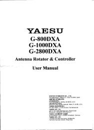
USING VEHICLE BATTERY POWER<br />
Follow these steps to connect the<br />
transceiver to your vehicle’s battery<br />
power.<br />
1. Connect the red wire (with inline<br />
fuse holder) from the<br />
back of the transceiver to a<br />
point in your vehicle's fuse<br />
block that has power only<br />
when the ignition is in the<br />
ACC (accessory) or ON position.<br />
2. Connect the black wire to a<br />
metal part of the vehicle's<br />
frame (chassis ground).<br />
Red wire to<br />
positive (+) terminal<br />
Black wire to<br />
negative (-) terminal<br />
13
Caution: Do not connect the black wire to a non-metallic<br />
(plastic) part, or to any part insulated from the vehicle's<br />
chassis by a non-metallic part.<br />
3. Connect the single connector end of the power cord to the<br />
connector on the back of the transceiver.<br />
USING THE TRANSCEIVER AS A BASE<br />
STATION<br />
Although this transceiver is designed mainly for mobile use, you<br />
can also use it as a base station with an AC power source. For<br />
base station installation, you need these items.<br />
14<br />
• a 12-volt DC power supply that can supply at least 7 amps<br />
Caution: Most 12-volt DC power supplies plug into a standard<br />
AC outlet to produce DC power. Before connecting<br />
your transceiver to a 12-volt DC power supply, read and follow<br />
the instructions included with the power supply.<br />
• base station antenna<br />
• coaxial antenna cable and connectors<br />
• external 8-ohm speaker<br />
Note: Your local <strong>Radio</strong>Shack store carries everything you<br />
need to use the transceiver as a base station.
Follow these steps to install the transceiver as a base station.<br />
1. Mount the base station antenna as described in its owner's<br />
manual.<br />
Warning: Use extreme caution when you install or remove<br />
a base station antenna. If the antenna starts to fall, let it go!<br />
It could contact overheard power lines. If the antenna<br />
touches a power line, contact with the antenna, mast, cable,<br />
or guy wires can cause electrocution and death. Call the<br />
power company to remove the antenna. DO NOT attempt to<br />
do so yourself.<br />
2. Connect the antenna to the ANT jack on the back of the<br />
transceiver.<br />
3. Connect the transceiver's black power wire to the negative<br />
(–) terminal on the DC power supply.<br />
4. Connect the transceiver's red wire (with in-line fuse holders)<br />
to the positive (+) terminal on the DC power supply.<br />
5. Connect the single–connector end of the power cord to the<br />
connector on the back of the transceiver.<br />
6. Connect the DC power supply to a standard AC outlet.<br />
15
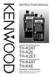
A QUICK LOOK AT THE CONTROLS<br />
OFF/VOLUME — turns the radio on/off; adjusts the volume<br />
RF-G/MIC-G — attenuates strong signals; reduces the microphone’s<br />
gain and SSB transmitting power<br />
STEP/NB/1 — selects the frequency tuning step; turns the noise<br />
blanker on/off; selects memory Channel 1<br />
CALL/2 — quickly recalls a frequency in memory Channel 2; selects<br />
memory Channel 2<br />
SCAN/SHIFT/3 — starts/stops scanning; selects the frequency<br />
shift; selects memory Channel 3<br />
LCR/4 — recalls the last tuned channel; selects memory Channel 4<br />
MODE/T-LOW/5 — selects the operation band, AM/FM/USB/LSB;<br />
turns hi-cut filter on/off; selects memory Channel 5<br />
M-LOAD/M-SAVE — loads from/saves to a memory location<br />
FINE/PUSH FUNC — adjusts fine tuning; activates second function<br />
SQUELCH — sets the squelch level to block weak signals<br />
TUNE — selects a frequency<br />
16
OPERATION<br />
SETTING SQUELCH AND RECEIVING<br />
1. Rotate SQUELCH fully counterclockwise.<br />
2. Rotate RF-G fully clockwise.<br />
3. To turn on the transceiver, rotate OFF/VOLUME clockwise<br />
until it clicks. <strong>The</strong> display lights and the frequency appears.<br />
A bar graph also appears which shows the received signal’s<br />
strength.<br />
Frequency<br />
Bar Graph<br />
4. Set OFF/VOLUME to a comfortable listening level.<br />
5. Rotate SQUELCH clockwise until you hear a hissing sound.<br />
<strong>The</strong>n slowly rotate SQUELCH counterclockwise just until the<br />
noise stops.<br />
17
Note: If the transceiver picks up unwanted weak transmissions,<br />
rotate RF-G slightly counterclockwise to decrease the<br />
transceiver’s sensitivity to signals. <strong>The</strong> transceiver blocks<br />
the weak transmissions.<br />
6. Repeatedly press MODE to select the desired band (FM,<br />
AM, USB (upper sideband), or LSB (lower sideband)).<br />
7. Rotate TUNE or press UP or DN on the top of the microphone<br />
to select a frequency.<br />
8. To turn off the transceiver, rotate OFF/VOLUME counterclockwise<br />
until it clicks.<br />
TRANSMITTING<br />
Notes:<br />
• Do not attempt to transmit unless you possess a valid amateur<br />
radio license.<br />
• We recommend you try receiving before you transmit.<br />
1. Follow Steps 1–7 in “Setting Squelch and Receiving” on<br />
Page 17.<br />
2. Turn MIC-G fully clockwise.<br />
18
3. To transmit, hold down the push-to-talk button on the microphone,<br />
hold the microphone 2–3 inches from your mouth,<br />
and speak in a normal tone of voice. TX appears along with<br />
a bar graph which shows the strength of your transmission.<br />
4. When you finish transmitting, release the PTT button. TX<br />
and the signal strength bars disappear.<br />
5. To turn off the transceiver, rotate OFF/VOLUME counterclockwise<br />
until it clicks.<br />
NOTES ON SSB RECEPTION<br />
• If the voice sounds distorted, slowly rotate FINE to bring the<br />
signal into its natural voice tonal range.<br />
• An SSB signal produces a fluttering, unintelligible sound<br />
when received in the AM mode. Set the mode switch to<br />
either LSB or USB, and adjust FINE. If the voice is still not<br />
intelligible, it might be an SSB signal operating on the other<br />
sideband — try the other SSB mode.<br />
19
SPECIAL FEATURES<br />
USING THE SPECIAL FEATURES<br />
Your transceiver has several advanced features that give you additional<br />
control and convenience while using it.<br />
This list provides additional information about your transceiver’s<br />
special features.<br />
20<br />
Feature See:<br />
Step — let’s you change the increment<br />
you set to tune frequencies in<br />
the <strong>10</strong>-meter band.<br />
Call — recalls a specific frequency in<br />
memory channel 2.<br />
Page 21<br />
Page 22<br />
Scan — scans incoming signals. Page 22<br />
Last Channel Recall — returns to the<br />
last channel that was transmitted.<br />
M-LOAD — recalls frequencies stored<br />
in memory Channels 1–5.<br />
NB (Noise Blanker) — reduces electrical<br />
noise.<br />
Shift — lets you set the frequency shift<br />
direction and offset frequency.<br />
T-LOW (Tone Low) — turns the highcut<br />
filter on or off.<br />
M-SAVE (Memory Save) — saves up<br />
to five frequencies into memory channels.<br />
FINE (Clarifier) — tunes in stations or<br />
tunes out interference broadcast using<br />
an SSB signal.<br />
Page 23<br />
Page 23<br />
Page 23<br />
Page 24<br />
Page 24<br />
Page 25<br />
Page 25
Using STEP<br />
Feature See:<br />
RF-G (RF Gain) — attenuates strong<br />
signals.<br />
MIC-G (Microphone Gain) —<br />
reduces the microphone gain and<br />
SSB transmitting power,<br />
Page 26<br />
Page 26<br />
Repeatedly press STEP to select the frequency step your transceiver<br />
displays when it shows a frequency. As you press STEP,<br />
one of the three frequency digits flashes for about 2 seconds to<br />
show which digit is selected. <strong>The</strong> increment that the selected<br />
digit displays is:<br />
• the rightmost digit: 1 kHz<br />
• the second digit from the right: <strong>10</strong> kHz<br />
• the third digit from the right: <strong>10</strong>0 kHz<br />
21
Using CALL<br />
<strong>The</strong> transceiver’s call memory lets you quickly recall a specific<br />
frequency in memory Channel 2.<br />
Note: See “Using M-SAVE (Memory Save)” on Page 25 for more<br />
information about storing a frequency in memory channel 2.<br />
Press CALL to recall the stored frequency at any time. <strong>The</strong> frequency<br />
flashes.<br />
Press CALL again and the last selected frequency appears.<br />
Using SCAN<br />
Press SCAN to scan incoming signals. SCAN appears and the<br />
transceiver stops for 5 seconds on each channel when it detects<br />
a signal.<br />
To stop scanning, press SCAN or the PTT button on the microphone.<br />
SCAN disappears.<br />
22
Using LCR (Last Channel Recall)<br />
Press LCR to return to the last channel you selected.<br />
Using M-LOAD<br />
You can recall frequencies stored in memory Channels 1–5.<br />
Note: See “Using M-SAVE (Memory Save)” on Page 25 for more<br />
information about storing frequencies in memory channels.<br />
To recall a memory channel, press M-LOAD so L appears, then,<br />
press the desired memory channel number.<br />
Using NB (Noise Blanker)<br />
If the transceiver’s reception is disturbed by interference from<br />
electrical noise (such as ignition noise), you can reduce the noise<br />
by using the transmitter’s noise blanker feature. To turn on or off<br />
the noise blanker, press PUSH FUNC then NB. NB appears while<br />
the noise blanker is on.<br />
23
Using SHIFT<br />
<strong>The</strong> transceiver’s shift function lets you set the transmit frequency<br />
shift from the receive frequency in either direction within the<br />
range of 0.0 Hz to 990 kHz.<br />
Follow these steps to set the frequency shift direction and offset<br />
frequency.<br />
1. To set the frequency shift direction to +, press PUSH FUNC<br />
then press SHIFT while FUNC appears. +SHIFT appears.<br />
Press PUSH FUNC and SHIFT again while FUNC appears to<br />
set the frequency shift direction to -. -SHIFT appears.<br />
2. Press PUSH FUNC then SHIFT for about 3 seconds. 000<br />
appears.<br />
3. Rotate TUNE to set the offset frequency to any frequency<br />
from 0 to 990 kHz.<br />
4. To exit, hold down PUSH FUNC and SHIFT together for about<br />
3 seconds.<br />
Using T-LOW (Tone-Low)<br />
Press PUSH FUNC then T-LOW to turn the high-cut filter on or off.<br />
LOW appears when the high-cut filter is on.<br />
24
Using M-SAVE (Memory Save)<br />
Follow these steps to save up to five frequencies into memory<br />
channels.<br />
1. Select the desired frequency.<br />
2. Press PUSH FUNC then M-SAVE. S appears.<br />
3. While S appears, press the desired memory channel number.<br />
<strong>The</strong> transceiver stores the frequency you selected into<br />
the memory channel you selected.<br />
4. To recall a frequency you stored, see “Using M-LOAD” on<br />
Page 23.<br />
Using FINE (Clarifier)<br />
When you listen to an SSB signal, rotate FINE to tune in slightly<br />
off-frequency stations or to tune out interference from adjacent<br />
channels.<br />
25
Using RF-G (RF Gain)<br />
When you receive an extremely strong signal, rotate RF-G counterclockwise<br />
to attenuate the signal.<br />
Using MIC-G (Microphone Gain)<br />
Rotate MIC-G to adjust the transmitter’s microphone gain and<br />
SSB transmitting power for the best audio quality.<br />
TURNING THE KEY TONE ON AND OFF<br />
<strong>The</strong> transceiver is preset to sound a tone each time you press a<br />
key. To turn the transceiver’s key tone on or off, turn on the transceiver<br />
while holding down the push-to-talk button on the microphone.<br />
26
CARE AND MAINTENANCE<br />
Your <strong>HTX</strong>-<strong>10</strong> <strong>10</strong>-Meter Transceiver is an example of superior<br />
design and craftsmanship. <strong>The</strong> following suggestions will help<br />
you care for your transceiver so you can enjoy it for years.<br />
Keep the transceiver dry. If it gets wet, wipe it dry<br />
immediately. Liquids might contain minerals that<br />
can corrode the electronic circuits.<br />
Use and store the transceiver only in normal temperature<br />
environments. Temperature extremes<br />
can shorten the life of electronic devices and distort<br />
or melt plastic parts.<br />
Keep the transceiver away from dust and dirt,<br />
which can cause premature wear of parts.<br />
Handle the transceiver gently and carefully.<br />
Dropping it can damage circuit boards and cases<br />
and can cause the transceiver to work improperly.<br />
Wipe the transceiver with a damp cloth occasionally<br />
to keep it looking new. Do not use harsh<br />
chemicals, cleaning solvents, or strong detergents<br />
to clean the transceiver.<br />
Modifying or tampering with the transceiver’s internal components<br />
can cause a malfunction and might invalidate its warranty<br />
and void your FCC authorization to operate it. If your<br />
transceiver is not performing as it should, take it to your local<br />
<strong>Radio</strong>Shack store for assistance.<br />
27
TROUBLESHOOTING<br />
If your transceiver is not working as it should, these suggestions<br />
might help you eliminate the problem. If the transceiver still does<br />
not operate properly, take it to your local <strong>Radio</strong>Shack store for assistance.<br />
28<br />
Problem Possible Causes Remedies<br />
Trouble with<br />
reception.<br />
Trouble with<br />
transmission.<br />
<strong>The</strong> squelch might<br />
need to be adjusted.<br />
<strong>The</strong> transmitter<br />
might not be set to<br />
an operating frequency.<br />
<strong>The</strong> microphone<br />
might not be connected.<br />
<strong>The</strong> antenna might<br />
not be connected.<br />
<strong>The</strong> receive mode<br />
might not be properly<br />
set.<br />
<strong>The</strong> antenna might<br />
not be connected.<br />
<strong>The</strong> microphone<br />
might not be connected.<br />
<strong>The</strong> microphone’s<br />
push–to–talk button<br />
might not be fully<br />
pressed in.<br />
Adjust the<br />
squelch.<br />
Tune the transceiver<br />
to an operating<br />
frequency.<br />
Make sure the<br />
microphone is<br />
connected.<br />
Make sure the<br />
antenna is connected.<br />
Set the receive<br />
mode to FM, AM,<br />
LSB, or USB.<br />
Make sure the<br />
antenna is connected.<br />
Make sure the<br />
microphone is<br />
connected.<br />
Press the microphone’s<br />
button in<br />
fully.
Problem Possible Causes Remedies<br />
Trouble with<br />
transmission<br />
(continued)<br />
Transceiver<br />
does not work<br />
at all.<br />
<strong>The</strong> microphone’s<br />
gain might not be<br />
properly set.<br />
<strong>The</strong> power cord<br />
might not be connected.<br />
<strong>The</strong> transceiver should be serviced only by a qualified radio<br />
technician. If you still have problems, take your transceiver to a<br />
local <strong>Radio</strong>Shack store for assistance.<br />
NOISE REDUCTION<br />
<strong>The</strong> power cord’s<br />
fuse might be blown.<br />
Adjust MIC-G.<br />
Make sure the<br />
power cord is connected.<br />
Replace the fuse<br />
(see “Replacing<br />
the Fuse” on Page<br />
30).<br />
Because your transceiver is exceptionally quiet, any noise you<br />
hear is probably from an external source in your vehicle such as<br />
your vehicle’s alternator, radio, or spark plugs.<br />
To solve the problem, you must go to the noise's source. You<br />
can determine the noise's source by turning off the engine and<br />
operating the transceiver with your vehicle's ignition set to ACC.<br />
If the noise decreases, the problem is in your vehicle’s ignition<br />
or electrical system.<br />
Here are a few hints to help you reduce or eliminate such<br />
noise:<br />
• Make all transceiver power and antenna wires as short as<br />
possible.<br />
• Route the power wires away from the antenna wires.<br />
29
• Be sure that the chassis ground connection is secure.<br />
• Replace old ignition wires with new, high-voltage, noise suppression<br />
wires.<br />
• Install noise suppressors on your spark plugs, or install new<br />
spark plugs that have built in noise suppressors.<br />
• If problems persist, check your alternator/generator and regulator<br />
gauges. You can reduce the noise from these sources<br />
by using bypass capacitors at the various output voltage<br />
points.<br />
Your local <strong>Radio</strong>Shack store has a wide selection of noise suppression<br />
accessories.<br />
REPLACING THE FUSE<br />
If the <strong>HTX</strong>-<strong>10</strong> stops operating, you might need to replace the red<br />
power wire’s fuse with the supplied spare fuse.<br />
Caution: Do not use a fuse with ratings other than those specified<br />
here. Doing so might damage your transceiver.<br />
Follow these steps to replace your transceiver’s fuse.<br />
1. Make sure the power source and transceiver are both off.<br />
2. Pull the latches apart on the fuse holder until it opens.<br />
30<br />
3. If the fuse is blown, replace it. Use only a standard 1 1 /4 × 1 /4<br />
inch fast-acting fuse with the proper rating. <strong>The</strong> fuse must<br />
be <strong>10</strong> amps.
Caution: <strong>The</strong> supplied fuse has the proper ratings. Make<br />
sure you replace a fuse only with another fuse of the same<br />
rating.<br />
4. Reassemble the fuse holder by squeezing it together until it<br />
snaps shut.<br />
31
SPECIFICATIONS<br />
GENERAL<br />
Frequency Range ........................... 28.000 MHz to 29.699 MHz<br />
Tuning Step ......................... 1 kHz/<strong>10</strong> kHz/<strong>10</strong>0 kHz (selectable)<br />
Frequency Generation ........................... Digital PLL Synthesizer<br />
Antenna Connector ............................ 50 ohm coaxial connector<br />
Microphone ........................................... Electret condenser type<br />
Operating Temperature ................... –4° to 122°F (–<strong>10</strong>° to 55°C)<br />
Power Source ............. 12–16V DC, negative or positive ground<br />
Speaker ................................................................ 8 ohm, 2 watt<br />
Impedance ...................................................................... 50 ohm<br />
Dimensions (HWD) ........................... 61 /16 × 23 /64 × 941/64 inches<br />
(154 × 52 × 248 mm)<br />
Weight (without batteries)................................................. 2.65 lb<br />
(1.2 kg)<br />
Accessories ............................ Microphone, Microphone Holder,<br />
Mounting Hardware, Mounting Bracket,<br />
DC Power Cord, Spare Fuse<br />
RECEIVER<br />
Sensitivity .................................................. 0.5 μV for <strong>10</strong> dB S/N<br />
Audio Output @ <strong>10</strong>% THD (External) ................ 2.5 W at 8 ohm<br />
Selectivity ................................................................... 50 dB min<br />
Intermodulation ........................................................... 60 dB min<br />
Distortion ..................................................................... <strong>10</strong>% max<br />
S/N Ratio .................................................................... 40 dB min<br />
IF Rejection ........................................................ 70 dB or better<br />
32
TRANSMITTER<br />
Power Output ....................................... 7w (AM), 25w (FM/SSB)<br />
Distortion ............................................................................... 5%<br />
Deviation ......................................................................... ±2 kHz<br />
S/N Ratio............................................................................ 40 dB<br />
Spurious Emission ............................................ –65 dB or better<br />
Battery Drain:<br />
At max output power ........................... AM Less than 3.0 A,<br />
FM Less than 5.0 A, SSB 5.0 A<br />
At no modulation ................................. AM Less than 3.0 A,<br />
FM Less than 5.0 A, SSB 1.0 A<br />
Specifications are typical; individual units might vary. Specifications<br />
are subject to change and improvement without notice.<br />
33
NOTES<br />
34
Limited Ninety-Day Warranty<br />
This product is warranted by <strong>Radio</strong>Shack against manufacturing defects in material<br />
and workmanship under normal use for ninety (90) days from the date of purchase<br />
from <strong>Radio</strong>Shack company-owned stores and authorized <strong>Radio</strong>Shack franchisees<br />
and dealers. EXCEPT AS PROVIDED HEREIN, <strong>Radio</strong>Shack MAKES NO EX-<br />
PRESS WARRANTIES AND ANY IMPLIED WARRANTIES, INCLUDING THOSE<br />
OF MERCHANTABILITY AND FITNESS FOR A PARTICULAR PURPOSE, ARE<br />
LIMITED IN DURATION TO THE DURATION OF THE WRITTEN LIMITED WAR-<br />
RANTIES CONTAINED HEREIN. EXCEPT AS PROVIDED HEREIN, <strong>Radio</strong>Shack<br />
SHALL HAVE NO LIABILITY OR RESPONSIBILITY TO CUSTOMER OR ANY<br />
OTHER PERSON OR ENTITY WITH RESPECT TO ANY LIABILITY, LOSS OR<br />
DAMAGE CAUSED DIRECTLY OR INDIRECTLY BY USE OR PERFORMANCE<br />
OF THE PRODUCT OR ARISING OUT OF ANY BREACH OF THIS WARRANTY,<br />
INCLUDING, BUT NOT LIMITED TO, ANY DAMAGES RESULTING FROM INCON-<br />
VENIENCE, LOSS OF TIME, DATA, PROPERTY, REVENUE, OR PROFIT OR ANY<br />
INDIRECT, SPECIAL, INCIDENTAL, OR CONSEQUENTIAL DAMAGES, EVEN IF<br />
<strong>Radio</strong>Shack HAS BEEN ADVISED OF THE POSSIBILITY OF SUCH DAMAGES.<br />
Some states do not allow limitations on how long an implied warranty lasts or the exclusion<br />
or limitation of incidental or consequential damages, so the above limitations<br />
or exclusions may not apply to you.<br />
In the event of a product defect during the warranty period, take the product and the<br />
<strong>Radio</strong>Shack sales receipt as proof of purchase date to any <strong>Radio</strong>Shack store. <strong>Radio</strong>Shack<br />
will, at its option, unless otherwise provided by law: (a) correct the defect<br />
by product repair without charge for parts and labor; (b) replace the product with one<br />
of the same or similar design; or (c) refund the purchase price. All replaced parts<br />
and products, and products on which a refund is made, become the property of <strong>Radio</strong>Shack.<br />
New or reconditioned parts and products may be used in the performance<br />
of warranty service. Repaired or replaced parts and products are warranted for the<br />
remainder of the original warranty period. You will be charged for repair or replacement<br />
of the product made after the expiration of the warranty period.<br />
This warranty does not cover: (a) damage or failure caused by or attributable to acts<br />
of God, abuse, accident, misuse, improper or abnormal usage, failure to follow instructions,<br />
improper installation or maintenance, alteration, lightning or other incidence<br />
of excess voltage or current; (b) any repairs other than those provided by a<br />
<strong>Radio</strong>Shack Authorized Service Facility; (c) consumables such as fuses or batteries;<br />
(d) cosmetic damage; (e) transportation, shipping or insurance costs; or (f) costs<br />
of product removal, installation, set-up service adjustment or reinstallation.<br />
This warranty gives you specific legal rights, and you may also have other rights<br />
which vary from state to state.<br />
<strong>Radio</strong>Shack Customer Relations, 200 Taylor Street, 6th Floor, Fort Worth, TX 76<strong>10</strong>2<br />
We Service What We Sell 12/99<br />
<strong>Radio</strong>Shack<br />
A Division of Tandy Corporation<br />
Fort Worth, Texas 76<strong>10</strong>2<br />
03A00 Printed in Korea