FT-817ND OM - Yaesu UK Ltd
FT-817ND OM - Yaesu UK Ltd
FT-817ND OM - Yaesu UK Ltd

You also want an ePaper? Increase the reach of your titles
YUMPU automatically turns print PDFs into web optimized ePapers that Google loves.
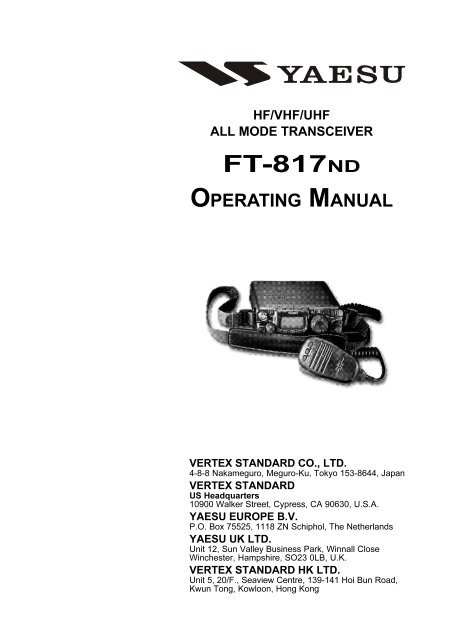
HF/VHF/UHF<br />
ALL MODE TRANSCEIVER<br />
<strong>FT</strong>-<strong>817ND</strong><br />
OPERATING MANUAL<br />
VERTEX STANDARD CO., LTD.<br />
4-8-8 Nakameguro, Meguro-Ku, Tokyo 153-8644, Japan<br />
VERTEX STANDARD<br />
US Headquarters<br />
10900 Walker Street, Cypress, CA 90630, U.S.A.<br />
YAESU EUROPE B.V.<br />
P.O. Box 75525, 1118 ZN Schiphol, The Netherlands<br />
YAESU <strong>UK</strong> LTD.<br />
Unit 12, Sun Valley Business Park, Winnall Close<br />
Winchester, Hampshire, SO23 0LB, U.K.<br />
VERTEX STANDARD HK LTD.<br />
Unit 5, 20/F., Seaview Centre, 139-141 Hoi Bun Road,<br />
Kwun Tong, Kowloon, Hong Kong
Introduction .................................................... 1<br />
Specifications .................................................. 2<br />
Accessories & Options ................................... 4<br />
Plug Pinout ...................................................... 5<br />
Installation ...................................................... 6<br />
Connecting the Supplied YHA-63 Antenna ......... 6<br />
Connecting the Microphone ................................. 7<br />
Shoulder Strap Installation ................................... 7<br />
Rubber Foot Installation ....................................... 7<br />
Alkaline Battery Installation and Use .................. 8<br />
External Power Connections ................................ 9<br />
FNB-85 Ni-Cd Battery Pack Installation and Use .. 10<br />
Front Panel Control & Switches ................. 12<br />
Side Panel Switch & Connectors ................ 16<br />
Rear Panel Connectors ................................ 17<br />
Operation ...................................................... 18<br />
Turning the Transceiver On and Off .................. 18<br />
Supply Voltage Display ...................................... 18<br />
Operating Band Selection .................................. 19<br />
Mode Selection ................................................... 19<br />
Adjusting the Audio Volume Level .................... 19<br />
Menu Quick Start ............................................... 20<br />
Adjusting the RF Gain and Squelch ................... 20<br />
Setting the Operating Frequency ........................ 21<br />
Stacked VFO System ......................................... 21<br />
Operation on 5 MHz Band<br />
(U.S. Version Only) ............................................ 22<br />
Receiver Accessories ..................................... 23<br />
Clarifier (Receiver incremental Tuning) ............ 23<br />
IF SHI<strong>FT</strong> ............................................................ 24<br />
AGC (Automatic Gain Control) ......................... 25<br />
Noise Blanker ..................................................... 25<br />
IPO (Intercept Point Optimization) .................... 25<br />
ATT (Front End Attenuator) ............................... 26<br />
AM/FM DIAL .................................................... 26<br />
Automatic Power-Off Feature ............................ 27<br />
Transmitter Operation ................................. 28<br />
SSB Transmission .............................................. 28<br />
Basic Setup/Operation ................................... 28<br />
Adjusting the transmitter Power Output ... 28<br />
VOX Operation ............................................. 29<br />
CW Transmission ............................................... 30<br />
Operation using Straight Key/<br />
External Keying Device ................................ 30<br />
Operation using<br />
the Built-in Electronic Keyer ........................ 32<br />
Contents<br />
FM Transmission ................................................ 33<br />
Basic Setup/Operation ................................... 33<br />
Repeater Operation ........................................ 33<br />
Tone Search Scanning ............................... 35<br />
DCS Operation .............................................. 36<br />
DCS Search Scanning ............................... 36<br />
ARTS TM (Auto Range Transpond System)<br />
Operation ....................................................... 37<br />
CW Identifier Setup ....................................... 37<br />
Digital Mode Operation (SSB-Based AFSK) .... 38<br />
RTTY (Radio TeleType) Operation ............... 38<br />
PSK31 Operation ........................................... 39<br />
“USER” Defined Digital Modes ................... 40<br />
Packet (1200/9600 bps FM) Operation .............. 41<br />
AM Transmission ............................................... 42<br />
Split Frequency Operation ................................. 42<br />
Time-Out Timer .................................................. 43<br />
WeatherFax Monitoring ..................................... 43<br />
Memory Operation ...................................... 44<br />
QMB Channel ..................................................... 44<br />
Memory Operation on<br />
“Regular” Memory Channels ............................. 45<br />
Normal Memory Storage .............................. 45<br />
Split-Frequency Memory Storage ................. 45<br />
Memory Channel Recall ................................ 46<br />
Masking Memory .......................................... 47<br />
Memory Operation on<br />
“H<strong>OM</strong>E” Channel Memories ............................. 48<br />
Labeling Memories ............................................ 49<br />
Spectrum Scope Monitor Operation .......... 50<br />
Smart Search TM Operation .......................... 51<br />
Scanning Operation ..................................... 52<br />
Scanning Operation ............................................ 52<br />
Scan Skip Programming (Memory Mode Only) .... 52<br />
Scan-Resume Choices .............................. 52<br />
Programmable Memory Scan (PMS) Operation . 54<br />
Dual Watch Operation ................................. 56<br />
Operation on Alaska Emergency Frequency:<br />
5167.5 kHz (U.S. Version Only) ........................ 57<br />
Menu Operation ........................................... 58<br />
Clonning ........................................................ 69<br />
CAT System Programming ....................... 70<br />
Installation of Optional Accessories ........... 74<br />
Option Filters YF-122S/YF-122C ................... 74<br />
High-Stability Reference Oscillator TCXO-9 ... 75<br />
Power-on Microprocessor Reset Procedure ..... 76<br />
Appendix ....................................................... 77<br />
Setup of Memories for Low Earth Orbit (LEO)<br />
FM Satellite Operation ....................................... 77<br />
BAND DATA Format ......................................... 80
<strong>FT</strong>-<strong>817ND</strong> Operating Manual<br />
INTRODUCTION<br />
The <strong>FT</strong>-<strong>817ND</strong> is a compact, innovative multiband, multimode portable transceiver for the<br />
amateur radio MF/HF/VHF/UHF bands. Providing coverage of the 160-10 meter bands<br />
(include the 60 m band: USA version) plus the 6 m, 2 m, and 70 cm bands, the <strong>FT</strong>-<strong>817ND</strong><br />
includes operation on the SSB, CW, AM, FM, and Digital modes, yielding the most comprehensive<br />
performance package available for portable operation.<br />
Designed for use either from an external DC power source or internal batteries, the <strong>FT</strong>-<br />
<strong>817ND</strong> provides five watts of power output from a 13.8-Volt external power supply. When<br />
using the FNB-85 Ni-MH Battery Pack or 8 “AA” Alkaline Cells (not supplied), the <strong>FT</strong>-<br />
<strong>817ND</strong> automatically switches to 2.5 Watts of output power. Via the Menu system, “High”<br />
power may be selected during battery operation, providing as much as 5 Watts of output,<br />
depending on the operating frequency.<br />
The multi-function Liquid-Crystal Display includes Blue, Amber, and Violet backlighting,<br />
which may be disabled for battery conservation. The display includes bar-graph indication<br />
of power output, ALC voltage, SWR, and modulation level. Also include are a number of<br />
operating status icons, as well as the function displays for the three operating function keys<br />
( , , and ).<br />
Among the advanced features of the <strong>FT</strong>-<strong>817ND</strong> are many incorporated only in large basestation<br />
transceivers. These include Dual VFOs; Split-Frequency operation; IF Shift; Clarifier<br />
(“R.I.T.”); IF Noise Blanker; AGC Fast/Slow/Auto/Off selection; RF Gain and Squelch<br />
control; IPO (Intercept Point Optimization) and a receiver front-end Attenuator; AM Aircraft<br />
reception; AM and FM Broadcast reception; VOX; Built-in Electronic Keyer; Adjustable<br />
CW Pitch; Automatic FM Repeater Shift (ARS); Built-in CTCSS Encoder/Decoders;<br />
ARTS (Auto-Range Transponder System); Smart Search Automatic Memory Loading<br />
System; Spectrum Scope; 200 Memories plus Home Channels and Band-limiting Memories;<br />
Alpha-Numeric Labeling of Memories; Automatic Power-Off (APO) and Time-Out<br />
Timer (TOT) functions; Computer Interface capability; and Cloning capability.<br />
We urge you to read this manual in its entirety, so as to gain a full understanding of the<br />
amazing capability of the exciting <strong>FT</strong>-<strong>817ND</strong> Portable Transceiver.<br />
1
SPECIFICATIONS<br />
GENERAL<br />
Frequency Range: Receive: 100 kHz-30 MHz<br />
50 MHz-54 MHz<br />
76 MHz-108 MHz (WFM only)<br />
87.5 MHz-108 MHz (EU)<br />
108 MHz-154 MHz (USA)<br />
144 MHz-148 (146) MHz (Other markets)<br />
430 (420) MHz-450 (440) MHz<br />
Transmit: 160-6 Meters (USA: includes 60 meters)<br />
2 Meters<br />
70 Centimeters (Amateur bands only)<br />
5.1675 MHz Alaska Emergency Frequency (USA only)<br />
Emission Modes: A1 (CW), A3 (AM), A3J (LSB/USB), F3 (FM),<br />
F1 (9600 bps packet), F2 (1200 bps packet)<br />
Synthesizer Steps (Min.): 10 Hz (CW/SSB), 100 Hz (AM/FM)<br />
Antenna Impedance: 50 Ohms, Unbalanced (Front: Type BNC, Rear: Type M)<br />
Operating Temp. Range: –10 °C to +60 °C (+14 °F to +140 °F)<br />
Frequency Stability: ±4 ppm from 1 min. to 60 min after power on.<br />
@25 °C: 1 ppm/hour<br />
±0.5 ppm/1 hour @25 °C, after warmup (with optional TCXO-9)<br />
Supply Voltage: Normal: 13.8 VDC ± 15 %, Negative Ground<br />
Operating: 8.0-16.0 V, Negative Ground<br />
FBA-28 (w/8 “AA” Alkaline Cells): 12.0 V<br />
FNB-85 (Ni-MH Battery Pack): 9.6 V<br />
Current Consumption: Squelched: 250 mA (Approx.)<br />
Receive: 450 mA<br />
Transmit: 2.0 A<br />
Case Size (W x H x D): 135 x 38 x 165 mm (5.31” x 1.5” x 6.50”)<br />
Weight (Approx.): 1.17 kg (2.58 lb) w/Alkaline battery, antenna, w/o Microphone<br />
TRANSMITTER<br />
RF Power Output: 5 W (SSB/CW/FM), 1.5 W (AM Carrier) @13.8 V<br />
Modulation Types: SSB: Balanced Modulator<br />
AM: Early Stage (Low Level)<br />
FM: Variable Reactance<br />
FM Maximum Deviation: ±5 kHz (FM-N: ±2.5 kHz)<br />
Spurious Radiation: –50 dB (1.8-29.7 MHz)<br />
–60 dB (50/144/430 MHz)<br />
Carrier Suppression: >40 dB<br />
Opp. Sideband Supp.: >50 dB<br />
SSB Frequency Response: 400 Hz-2600 Hz (–6 dB)<br />
Microphone Impedance: 200-10k Ohms (Nominal: 600 Ohms)<br />
2 <strong>FT</strong>-<strong>817ND</strong> Operating Manual
<strong>FT</strong>-<strong>817ND</strong> Operating Manual<br />
SPECIFICATIONS<br />
RECEIVER<br />
Circuit Type: Double-Conversion Superheterodyne<br />
Intermediate Frequencies: 1st: 68.33 MHz (SSB/CW/AM/FM); 10.7 MHz (WFM)<br />
2nd: 455 kHz<br />
Sensitivity: SSB/CW AM FM<br />
100 kHz-500 kHz – – –<br />
500 kHz-1.8 MHz – 32 µV –<br />
1.8 MHz-28 MHz 0.25 µV 2 µV –<br />
28 MHz-30 MHz 0.25 µV 2 µV 0.5 µV<br />
50 MHz-54 MHz 0.2 µV 2 µV 0.32 µV<br />
144/430 MHz 0.125 µV – 0.2 µV<br />
(IPO, ATT off, SSB/CW/AM = 10 dB S/N, FM = 12 dB SINAD)<br />
Squelch Sensitivity: SSB/CW/AM FM<br />
1.8 MHz-28 MHz 2.5 µV –<br />
28 MHz-30 MHz 2.5 µV 0.32 µV<br />
50 MHz-54 MHz 1 µV 0.2 µV<br />
144/430 MHz 0.5 µV 0.16 µV<br />
(IPO, ATT off)<br />
Image Rejection: HF/50 MHz: 70 dB<br />
144/430 MHz: 60 dB<br />
IF Rejection: 60 dB<br />
Selectivity (–6/–60 dB): SSB/CW: 2.2 kHz/4.5 kHz<br />
AM: 6 kHz/20 kHz<br />
FM: 15 kHz/30 kHz<br />
FM-N: 9 kHz/25 kHz<br />
SSB (optional YF-122S installed): 2.3 kHz/4.7 kHz (–66 dB)<br />
CW (optional YF-122C installed): 500 Hz/2.0 kHz<br />
CW (optional YF-122CN installed): 300 Hz/1.0 kHz<br />
AF Output: 1.0 W (8 Ohms, 10% THD or less)<br />
AF Output Impedance: 4-16 Ohms<br />
Specifications are subject to change without notice, and are guaranteed within amateur<br />
bands only.<br />
Frequency ranges vary according to transceiver version; check with your dealer.<br />
3
ACCESSORIES & OPTIONS<br />
SUPPLIED ACCESSORIES<br />
MH-31A8J Hand Microphone<br />
FNB-85 Ni-MH Battery Pack (9.6 V, 1400 mAh)<br />
NC-72B/C/U Battery Charger<br />
FBA-28 Battery Case (holds 8 “AA” size Alkaline cells [not supplied])<br />
YHA-63 Whip Antenna for (50/144/430 MHz)<br />
E-DC-6 DC Cable<br />
Shoulder Strap<br />
Ferrite Core<br />
Rubber Foot<br />
Available Options<br />
FNB-85 Ni-MH Battery Pack (9.6 V, 1400 mAh)<br />
FNB-72 Ni-Cd Battery Pack (9.6 V, 1000 mAh)<br />
NC-72B/C/U Battery Charger<br />
YF-122S Collins SSB Filter (2.3 kHz/4.7 kHz: –6 dB/–66 dB)<br />
YF-122C Collins CW Filter (500 Hz/2 kHz: –6 dB/–60 dB)<br />
YF-122CN Collins CW Filter (300 Hz/1 kHz: –6 dB/–60 dB)<br />
TCXO-9 TCXO Unit (±0.5 ppm)<br />
MH-36E8J DTMF Microphone<br />
CT-62 CAT Interface Cable<br />
CT-39A Packet Cable<br />
: “B” suffix is for use with 120 VAC, “C” suffix is for use with 230-240 VAC, and “U”<br />
suffix is for use with 230 VAC.<br />
4 <strong>FT</strong>-<strong>817ND</strong> Operating Manual
<strong>FT</strong>-<strong>817ND</strong> Operating Manual<br />
PLUG PINOUT<br />
5
INSTALLATION<br />
CONNECTING THE SUPPLIED YHA-63 ANTENNA<br />
Your <strong>FT</strong>-<strong>817ND</strong> is supplied with a three-section antenna, model YHA-63 which is designed<br />
for optimum performance on the 50 MHz, 144 MHz, and 430 MHz. It also works well on<br />
the FM broadcast and other VHF bands. This antenna is intended for connection to the front<br />
panel’s BNC-type antenna connector.<br />
For HF and/or 50 MHz operation, most hikers carry their own dipole or collapsible vertical<br />
antenna, fed by a small-diameter coaxial cable terminated in a type “M” (PL-259) plug, and<br />
these kinds of antennas may be connected to the rear panel’s antenna connector.<br />
The YHA-63 should be connected to the top panel’s “BNC” connector, using the following<br />
guidelines:<br />
For 144/430 MHz operation (only), connect the shorter cap section to the screw post on<br />
the top of the main antenna shaft, then screw the assembled YHA-63 onto the BNC<br />
connector, twisting it 1/4 turn clockwise to secure the antenna.<br />
For 50 MHz operation, unscrew the<br />
short cap section, and replace it with<br />
the long cap section. The long cap<br />
section will provide good results on<br />
144/430 MHz, as well, but those<br />
owners not using 50 MHz may prefer<br />
the shorter total length of the<br />
YHA-63 when using the short cap<br />
on 144/430 MHz.<br />
For shortwave listening using a random-length<br />
wire antenna for reception<br />
only, you may wish to consider<br />
connection of the wire between the<br />
main YHA-63 shaft and the cap,<br />
using a “spade lug” or similar lug<br />
on the end of the wire to provide a<br />
secure connection between the cap<br />
and the rest of the antenna.<br />
Menu #07 (“ANTENNA”) allows<br />
you to define which connector<br />
(“Front” or “Rear”) is used on a<br />
particular band. See page 60 for details.<br />
6 <strong>FT</strong>-<strong>817ND</strong> Operating Manual
<strong>FT</strong>-<strong>817ND</strong> Operating Manual<br />
CONNECTING THE MICROPHONE<br />
INSTALLATION<br />
To connect the microphone, plug its connector (latch side UP) into the MIC jack on the<br />
right side of the transceiver. Press it<br />
gently inward until you hear the<br />
“click” of the latch.<br />
To disconnect the microphone, press<br />
gently on the “PUSH ” label on<br />
top of the microphone connector’s rubber boot.<br />
While pressing on this spot, gently pull the connector<br />
outward from the body of the transceiver.<br />
Note: During “Digital” or “Packet” operation, it is not necessary to disconnect the microphone,<br />
as activation of the PTT line from the DATA connector automatically cuts off the<br />
audio input from the MIC jack.<br />
SHOULDER STRAP INSTALLATION<br />
The convenient Shoulder Strap is designed for maximum comfort and security for your <strong>FT</strong>-<br />
<strong>817ND</strong> transceiver.<br />
Refer to the illustration, and connect the<br />
shoulder strap to the attachment tabs just<br />
behind the front panel of the <strong>FT</strong>-<strong>817ND</strong>.<br />
Be sure to have the shoulder strap aligned<br />
correctly, without twists in the straps.<br />
A convenient microphone hanger is located<br />
on one end of the padded top section of<br />
the Shoulder Strap. When not in use, the<br />
microphone may be affixed here, freeing<br />
both of your hands for other tasks.<br />
RUBBER FOOT INSTALLATION<br />
Four Rubber Feet are provided with your <strong>FT</strong>-<br />
<strong>817ND</strong>, for ease of use when operating from a<br />
base station or camp table.<br />
Refer to the illustration, and affix the Rubber<br />
Feet in the appropriate locations.<br />
☞<br />
☞<br />
☞<br />
☞<br />
7
INSTALLATION<br />
LKALINE BATTERY INSTALLATION AND USE<br />
The <strong>FT</strong>-<strong>817ND</strong> is supplied with the FBA-28 holder for Alkaline “AA” cells. A fresh set of<br />
Alkaline cells should provide approximately 5.5 hours of reception under typical conditions.<br />
1. To install or replace the AA cells, first remove the battery cover from the bottom side of<br />
the transceiver. Slide the battery cover latch forward, as shown in the illustration, then<br />
fold the battery cover upward and set it aside temporarily.<br />
2. Install the Alkaline AA cells as shown in the illustration, paying particular attention to<br />
the correct polarity of the batteries.<br />
3. When all batteries have been successfully installed, replace the battery cover.<br />
Important Notes<br />
When the transceiver is to be stored for a long period of time without use (longer<br />
than ten days), remove the batteries from the FBA-28 holder, to avoid the possibility<br />
of battery leaking causing damage to the transceiver. Inspect the FBA-28<br />
battery holder occasionally for signs of corrosion or battery leakage, and remove<br />
the batteries immediately if any such damage is observed.<br />
The FBA-28 battery holder is designed for use solely with Alkaline type “AA”<br />
cells. Do not attempt to use Ni-Cd or other rechargeable cells in the FBA-28,<br />
because it does not contain the protection circuitry required when using rechargeable<br />
cells.<br />
When replacing batteries, replace all eight AA cells simultaneously with fresh<br />
batteries.<br />
When the battery voltage is approaching the value which indicates depletion is<br />
near, the small “ ” will blink, indicating it is time to replace the batteries.<br />
8 <strong>FT</strong>-<strong>817ND</strong> Operating Manual
<strong>FT</strong>-<strong>817ND</strong> Operating Manual<br />
INSTALLATION<br />
EXTERNAL POWER CONNECTIONS<br />
The <strong>FT</strong>-<strong>817ND</strong> may be connected to an external 13.8 Volt DC power source providing at<br />
least 3 Amps of continuous-duty current.. The supplied E-DC-6 DC cable may be used for<br />
DC connections.<br />
While connected to an external DC source, if you have installed the supplied FNB-85 Ni-<br />
MH Battery Pack, the E-DC-6 connection to the external DC power source will allow operation<br />
of the <strong>FT</strong>-<strong>817ND</strong> while charging of the FNB-85 is in progress.<br />
When making DC power connections, be absolutely certain to follow the markings on the E-<br />
DC-6 so as to ensure proper polarity of the connection to the power supply. Connect the RED<br />
AND BLACK wire to the Positive (+) power supply terminal, and connect the SOLID BLACK wire<br />
to the Negative (-) power supply terminal.<br />
<strong>FT</strong>-<strong>817ND</strong><br />
Notice<br />
Be extremely careful when making power supply connections. Use only a 13.8 Volt<br />
DC Supply, and carefully observe the proper electrical polarity. Serious damage may<br />
result if these precautions are not observed.<br />
The Limited Warranty on this product does not cover damage caused by improper<br />
power supply connections, or improper power supply voltage.<br />
9
INSTALLATION<br />
FNB-85 NI-MH BATTERY PACK INSTALLATION AND USE<br />
The supplied FNB-85 Ni-MH Battery Pack provides 9.6 Volts of DC power for your <strong>FT</strong>-<br />
<strong>817ND</strong>, with a maximum capacity of 1400 mAh.<br />
Installation<br />
1. To install the FNB-85 Ni-MH Battery Pack, first remove the battery compartment cover,<br />
as described previously.<br />
2. Lift out the FBA-28 battery holder, and disconnect the short cable connected to the<br />
FBA-28, as shown in the illustration.<br />
3. Connect the short cable to the mating connector on the FNB-85, and install the FNB-85<br />
in the battery compartment.<br />
4. Replace the battery compartment cover.<br />
FNB-85<br />
FBA-28<br />
10 <strong>FT</strong>-<strong>817ND</strong> Operating Manual
<strong>FT</strong>-<strong>817ND</strong> Operating Manual<br />
INSTALLATION<br />
FNB-85 NI-MH BATTERY PACK INSTALLATION AND USE<br />
Charging<br />
Charging of the FNB-85 requires the use of either the supplied NC-72B/C* charger, or an<br />
external 13.8 Volt (±15%) DC source. If the NC-72B/C is used, the <strong>FT</strong>-<strong>817ND</strong> must be<br />
turned off during charging; if an external 13.8 Volt DC source is used (connected via the<br />
supplied E-DC-6 cable), then you may operate the <strong>FT</strong>-<strong>817ND</strong> while charging is in progress.<br />
1. Turn the <strong>FT</strong>-<strong>817ND</strong> off (see page 18), then connect the supplied NC-72B/C DC connector<br />
to the INPUT: 13.8V jack on the rear panel of the <strong>FT</strong>-<strong>817ND</strong>.<br />
2. Plug the NC-72B/C into the nearest AC wall outlet.<br />
3. Press the <strong>FT</strong>-<strong>817ND</strong>’s switch for one second to turn the transceiver on.<br />
4. Press the key momentarily.<br />
5. Rotate the knob so that the function row containing “[CHG, VLT, DSP]” appears<br />
on the display.<br />
6. Press the key to select the [CHG] option (the display will immediately revert to the<br />
regular frequency display).<br />
7. Turn the <strong>FT</strong>-<strong>817ND</strong> off. You will now observe that the LED just<br />
above the main tuning dial is glowing Orange, and the display<br />
will indicate “CHG TIME RMN” and “7:59” to indicate the time<br />
remaining before a full charge is achieved on the FNB-85.<br />
Important Notice<br />
For Charging the optional FNB-72 Ni-Cd Battery Pack<br />
If you wish to charge the optional FNB-72 Ni-Cd Battery Pack using the supplied<br />
NC-72B/C Battery Charger, you must set the Battery Charging Time to “6 Hours”<br />
via Menu #11, to prevent over charging the battery. See page 61 for detail.<br />
11
FRONT PANEL CONTROL & SWITCHES<br />
PWR Switch<br />
Press and hold in the switch for one second to turn to the transceiver on or off.<br />
AF Knob<br />
The (inner) knob adjusts the receiver audio volume level presented to the internal<br />
or external speaker. Clockwise rotation increases the volume level.<br />
SQL/RF Knob<br />
In the USA version, this (outer) knob adjusts the gain of the receiver’s RF and<br />
IF stages. Using Menu Selection 45, this control may be changed to function as a Squelch<br />
control, which may be used to silence background noise when no signal is present. In<br />
the other versions, its default setting is set to “Squelch.”<br />
LOCK Key<br />
Pressing this key locks the front panel keys so as to prevent accidental frequency change.<br />
V/M Key<br />
Pressing this key switches frequency control between the VFO and Memory Systems.<br />
TRANSMIT/BUSY Indicator<br />
This LED glows green when the squelch opens, and turns red during transmit. It also<br />
glows orange during charging of the FNB-85 (Ni-MH) / FNB-72 (Ni-Cd) battery pack.<br />
MAIN Dial<br />
This is the main tuning dial for the transceiver. It is used both for frequency tuning as<br />
well as “Menu” setting in the transceiver.<br />
F Key<br />
Pressing this key momentarily changes the display to show the operating functions available<br />
via the , , keys.<br />
Press and hold this key for one second to activate the “Menu” mode.<br />
12 <strong>FT</strong>-<strong>817ND</strong> Operating Manual
FRONT PANEL CONTROL & SWITCHES<br />
FUNC Keys<br />
These three keys select many of the most important operating features of the transceiver.<br />
When pressing the key, the current function of that key appears above each<br />
of the , , keys (along the bottom of the LCD); rotating the knob<br />
scrolls the display through eleven rows of functions available for use via the , ,<br />
keys.<br />
The available features are shown in chart on the next page.<br />
BAND(DWN)/BAND(UP) Key<br />
Pressing either of these keys momentarily will cause the frequency to be moved up or<br />
down by one frequency band. The selections available are:<br />
Recalling the 5 MHz band (U.S. model) requires different procedure. See page 22 for<br />
details.<br />
MODE(⊳)/MODE() Key<br />
Pressing either of these keys momentarily will change the operating mode. The selections<br />
available are:<br />
H<strong>OM</strong>E Key<br />
Pressing this key momentarily recalls a favorite “H<strong>OM</strong>E” frequency memory.<br />
SEL Knob<br />
This detented rotary switch is used for tuning, memory selection, and function selection<br />
for the , , keys of the transceiver.<br />
CLAR Key<br />
Press this key momentarily to activate the Receiver Clarifier feature. When this feature<br />
is activated, the knob may be used to set a tuning offset of up to ±9.99 kHz. The<br />
transmitter’s frequency is not affected by the setting of the Clarifier.<br />
Press and hold this key for 1/2 second to activate the IF Shift feature, which allows you<br />
to use the knob to adjust the center frequency of the IF filter’s passband response.<br />
ANT Jack<br />
Connect the supplied 50/144/430 MHz rubber flex antenna (or another antenna presenting<br />
a 50Ω impedance) to this BNC connector.<br />
In its default setting, this jack does not function on the HF bands. If you want to enable<br />
this jack on the HF bands, recall and change the setting of Menu #07.<br />
<strong>FT</strong>-<strong>817ND</strong> Operating Manual<br />
13
FRONT PANEL CONTROL & SWITCHES<br />
1<br />
2<br />
3<br />
4<br />
5<br />
6<br />
7<br />
A/B<br />
Press the key to switch<br />
between VFO-A and VFO-B<br />
on the display.<br />
MW<br />
Press and hold in the key<br />
for 1/2 second to transfer the<br />
contents of the VFO into a<br />
Memory register.<br />
STO<br />
Press the key to store<br />
the contents of the VFO into<br />
the QMB (Quick Memory<br />
Bank) register.<br />
RPT<br />
Press the key to select<br />
the direction of the uplink frequency<br />
shift (“–,” “+,” or Simplex)<br />
during FM repeater operation.<br />
Press and hold in the key<br />
for 1/2 second to recall Menu<br />
#42 (for setting the shift frequency<br />
offset).<br />
SCN<br />
Press the key to initiate<br />
scanning (in the direction of<br />
higher frequencies).<br />
SSM<br />
Press the key to activate<br />
the Spectrum Scope Monitor<br />
feature.<br />
Press and hold in the key<br />
for 1/2 second to recall Menu<br />
#43 (for selecting the SSM<br />
sweep mode).<br />
IPO<br />
Press the key to bypass<br />
the receiver preamplifier,<br />
thereby activating Intercept<br />
Point Optimization for improved<br />
overload characteristics.<br />
The IPO feature does not<br />
function on 144/430 MHz.<br />
Key Key<br />
A=B<br />
Press and hold in the key<br />
for ½ second to copy the contents<br />
of VFO-A into the VFO-<br />
B register, so that the two<br />
VFOs’ contents will be identical.<br />
MC<br />
Press the key to designate<br />
the current Memory<br />
channel to be “skipped” during<br />
scanning.<br />
RCL<br />
Press the key to recall<br />
the QMB Memory.<br />
REV<br />
Press the key to reverse<br />
the transmit and receive frequencies<br />
while working<br />
through a repeater.<br />
PRI<br />
Press the key to activate<br />
the Priority Scan feature.<br />
SCH<br />
Press the key to activate<br />
Smart Search TM operation.<br />
ATT<br />
Press the key to engage<br />
the receiver front-end attenuator,<br />
which will reduce all signals<br />
and noise by approximately<br />
10 dB.<br />
The ATT feature does not<br />
function on 144/430 MHz.<br />
SPL<br />
Press the key to activate<br />
Split frequency operation between<br />
VFO-A and VFO-B.<br />
TAG<br />
Press the key to select<br />
the display type (Frequency<br />
or Alpha-numeric Tag) during<br />
Memory operation.<br />
PMS<br />
Press the key to activate<br />
the Programmable Memory<br />
Scan feature.<br />
TON<br />
Press the key to activate<br />
CTCSS or DCS operation.<br />
Press and hold in the key<br />
for 1/2 second to recall Menu<br />
#48 (for selecting the CTCSS<br />
tone frequency).<br />
DW<br />
Press the key to activate<br />
the Dual Watch system.<br />
ART<br />
Press the key to initiate<br />
the Auto-Range Transponder<br />
mode.<br />
Press and hold in the key<br />
for 1/2 second to recall Menu<br />
#09 (for selecting the ARTS<br />
“Beep” option).<br />
NAR<br />
Press the key to activate<br />
the “Narrow” filter mode in the<br />
CW (optional YF-122C or YF-<br />
122CN required) or SSB (optional<br />
YF-122S required)<br />
mode. On the FM mode, it<br />
also selects the low-deviation<br />
mode required for HF FM operation<br />
on 29 MHz.<br />
Press and hold in the key<br />
for 1/2 second to recall Menu<br />
#38 (to Enable/Disable the<br />
optional filter during installation).<br />
14 <strong>FT</strong>-<strong>817ND</strong> Operating Manual
8<br />
9<br />
10<br />
11<br />
12<br />
FRONT PANEL CONTROL & SWITCHES<br />
NB<br />
Press the key to activate<br />
the receiver’s IF Noise<br />
Blanker.<br />
PWR<br />
Press the key to select<br />
the transmitter power output<br />
level (LOW 1, LOW 2, LOW 3, or<br />
HIGH).<br />
VOX<br />
Press the key to enable<br />
the VOX (voice-operated<br />
transmitter switching system)<br />
in the SSB, AM, and FM<br />
modes.<br />
Press and hold in the key<br />
for 1/2 second to recall Menu<br />
#51 (for setting the VOX Gain<br />
level).<br />
CHG<br />
Press the key to initiate<br />
Battery Charging.<br />
Press and hold in the key<br />
for 1/2 second to recall Menu<br />
#11 (for selecting the Charging<br />
period).<br />
TCH<br />
Press the key to initiate<br />
Tone Search.<br />
<strong>FT</strong>-<strong>817ND</strong> Operating Manual<br />
Key Key Key<br />
AGC<br />
Press the key to select<br />
the recovery time (FAST, SLOW,<br />
A UTO, or O FF) for the<br />
receiver’s AGC system.<br />
MTR<br />
Press the key to select<br />
the display function of the<br />
meter in the transmit mode<br />
(Power, ALC, SWR, or MOD<br />
indication).<br />
BK<br />
Press the key to activate<br />
CW “Semi” Break-in operation.<br />
Press and hold in the key<br />
for 1/2 second to recall Menu<br />
#17 (for setting the CW Delay<br />
time). At a setting of 10<br />
ms, operation emulates full<br />
QSK performance.<br />
VLT<br />
Press the key to display<br />
the current battery voltage.<br />
DCH<br />
Press the key to initiate<br />
DCS Search.<br />
–<br />
No function<br />
–<br />
No function<br />
KYR<br />
Press the key to activate<br />
the built-in Electronic Keyer.<br />
Press and hold in the key<br />
for 1/2 second to recall Menu<br />
#21 (for setting the Keyer<br />
speed).<br />
DSP<br />
Press the key to switch<br />
the display between the Large<br />
Character and Small Character<br />
modes.<br />
–<br />
No function<br />
*The Operating Function number in this column does not appear on the LCD.<br />
Display Icons<br />
15
SIDE PANEL SWITCH & CONNECTORS<br />
MIC Jack<br />
Connect the supplied MH-31A8J Hand Microphone to this jack.<br />
SP/PH Jack<br />
This 3.5-mm, 2-pin jack provides variable audio output for an external speaker (4 Ω ~<br />
16 Ω impedance) or earphones. The audio level varies according to the setting of the<br />
front panel’s knob.<br />
When you insert an earphone plug into this jack, the SP-PH slide switch (located<br />
to the right side of this jack) MUST BE set to the “PH” position, to prevent<br />
the possibility of injury to your ears.<br />
SP-PH Switch<br />
If you use earphones with this transceiver, move this switch to the “PH” position before<br />
inserting the earphone plug into the SP/PH Jack, to prevent injury your ears.<br />
16 <strong>FT</strong>-<strong>817ND</strong> Operating Manual
<strong>FT</strong>-<strong>817ND</strong> Operating Manual<br />
REAR PANEL CONNECTORS<br />
INPUT:13.8V Jack ( )<br />
This is the DC power supply connection for the transceiver, used when operating the<br />
transceiver with an external power supply. Use the supplied DC cable to connect this<br />
jack to the car battery or base station DC power supply, which must be capable of<br />
supplying at least 3A @ 8 ~ 16 VDC. This jack is also used for battery charging (when<br />
using the supplied FNB-85 battery pack).<br />
GND Terminal<br />
For best performance and safety, this Ground lug may be connected to a good earth<br />
ground using a short, heavy, braided cable.<br />
KEY Jack<br />
This 3.5-mm, 3-pin jack is used for connection to a CW keyer paddle or a straight key.<br />
DATA Jack<br />
This 6-pin, mini-DIN jack accepts AFSK input from a Terminal Node Controller (TNC);<br />
it also provides fixed-level Receiver Audio Output, Push-To-Talk (PTT), Squelch Status,<br />
and ground lines.<br />
ACC Jack<br />
This 8-pin, mini-DIN jack provides a closure to ground during transmission, ALC, a<br />
transmitter-inhibit pin, and “band data” for connection to an external amplifier. It is also<br />
used for Transceiver-to Transceiver Cloning and for control of this transceiver using a<br />
personal computer.<br />
ANT Jack<br />
Connect your HF and/or 50 MHz antenna’s 50 Ω coaxial cable to this M-type (“SO-<br />
239”) connector.<br />
In its default setting, this jack does not function on 50/144/430 MHz bands. If you want to<br />
enable this jack on 50/144/430 MHz bands, recall and change the settings of Menu #07.<br />
17
OPERATION<br />
Hi! I’m R.F. Radio, and I’m here to guide you through the fine points of the setup<br />
and use of your new <strong>FT</strong>-<strong>817ND</strong>. I know your anxious to get on the air, but I<br />
encourage you to read the “Operation” section of this manual as thoroughly as possible,<br />
so you’ll get the most out of this fantastic new rig. Now. . .let’s get operating!<br />
TURNING THE TRANSCEIVER ON AND OFF<br />
1. To turn the transceiver on, press and hold in<br />
the switch for one second.<br />
2. To turn the transceiver off, again press and<br />
hold in the switch for one second.<br />
The one-second delay helps you avoid accidental<br />
switching on (or off) of DC power.<br />
SUPPLY VOLTAGE DISPLAY<br />
When you turn on the transceiver, the DC supply voltage is indicated<br />
in the upper right corner of the LCD for two seconds. After this interval,<br />
the display will resume its normal indication of the operating<br />
mode (VFOa, VFOb, or Memory Channel Number).<br />
To view the supply voltage at any time during operation:<br />
1. Press the key momentarily, then rotate the knob to select Operating Function<br />
Row 11* [CHG, VLT, DSP] on the display.<br />
2. Press the (VLT) key momentarily to display the supply voltage in the upper right<br />
corner of the LCD.<br />
3. To cancel the supply voltage display, again press the (VLT) key.<br />
Remember, the Operating Row Number does not appear on the display.<br />
18 <strong>FT</strong>-<strong>817ND</strong> Operating Manual
OPERATING BAND SELECTION<br />
This transceiver covers an incredibly wide frequency<br />
range, over which a number of different<br />
operating modes are used. Therefore, this<br />
transceiver’s frequency coverage has been divided<br />
into different operating bands, each of with has<br />
its own pre-set channel steps and operating modes.<br />
You can change the channel steps and operating mode once you get started, of course, per<br />
the next section.<br />
To change the frequency band, press either the or key to move to<br />
the next lower or higher operating band, respectively.<br />
1) Recalling the 5 MHz band (U.S. model) requires different procedure. See page<br />
22 for details.<br />
2) VFOa and VFOb are independent VFOs, so they may be set to different bands. See the<br />
“Stacked VFO System” discussion on page 21 for details.<br />
MODE SELECTION<br />
Press either the or key to<br />
move among the eight settings for the operating<br />
modes, respectively.<br />
You can also set VFOa and VFOb to different modes in the same band, allowing<br />
you to have a “Phone” VFO and a “CW” VFO, for example.<br />
ADJUSTING THE AUDIO VOLUME LEVEL<br />
Rotate the knob to set a comfortable listening<br />
level.<br />
When operating in the “DIG” or “PKT” modes,<br />
you may set the knob to any comfortable<br />
setting, or even all the way off, because the output<br />
from the DATA jack is a fixed-level audio signal.<br />
<strong>FT</strong>-<strong>817ND</strong> Operating Manual<br />
OPERATION<br />
Start with the knob set fully counter-clockwise, especially when using FM<br />
(the background noise on FM can be surprisingly loud)!<br />
19
OPERATION<br />
MENU QUICK START<br />
Many aspects of this transceiver’s configuration may be customized using the convenient<br />
“Menu” system, which allow you to configure many “set and forget” settings just the way<br />
you want to. A full discussion of the Menu system beings on page 58; for now, here is a brief<br />
discussion on how to change Menu settings:<br />
1. Press and hold in the key for one second to enter the Menu mode.<br />
2. Rotate the knob to recall the Menu item to be changed (for example, Menu #01,<br />
which Enables or Disables the Automatic Repeater Shift on the 144 MHz band).<br />
3. Rotate the knob to set this feature (in this example, the default setting is “EN-<br />
ABLE,” so rotate the knob to set this feature to “DISABLE.”<br />
4. Press and hold in the<br />
operation.<br />
key for one second to save the new setting and exit to normal<br />
If you have momentarily pressed the key to change an operating function,<br />
press the key momentarily again (to clear the function indications for the ,<br />
, keys) before engaging the Menu.<br />
ADJUSTING THE RF GAIN AND SQUELCH<br />
The control is configured differently,<br />
depending on the country to which the <strong>FT</strong>-<strong>817ND</strong><br />
has been exported. In the U.S. version, the default<br />
function of this control is “RF Gain.” The<br />
configuration of the control is set via<br />
Menu #45; see page 67 for details.<br />
If your transceiver is configured for “RF Gain” use, rotating this control fully clockwise in<br />
the SSB/CW/Digital modes will provide best sensitivity. To reduce the receiver’s RF Gain<br />
somewhat, rotate this control counter-clockwise slightly. You will observe an increasing<br />
number of bars on the S-meter as you rotate the control counter-clockwise; this<br />
indicates increasing AGC voltage, which is causing the front-end gain to be reduced. In the<br />
FM and Packet modes, this control will automatically be set to an “Auto-Squelch” mode,<br />
wherein the FM/Packet squelch threshold is pre-set at the factory; the control still<br />
acts as an “RF Gain” control, however, and it normally should be set fully clockwise.<br />
If this control is configured for “SQL” operation, the <strong>FT</strong>-<strong>817ND</strong>’s RF Gain will be set for<br />
maximum sensitivity in all modes, and the control will function solely as a Squelch<br />
control. In this case, rotate the control to the point where the background noise is<br />
just silenced; this will provide the best sensitivity to weak signals, while keeping the receiver<br />
quiet when no signal is received. The LED just above the Main Dial will glow Green<br />
when the squelch is opened by an incoming signal or noise.<br />
Battery consumption is significantly reduced if the receiver is squelched, as the<br />
audio amplifier stage is shut off when the receiver is muted.<br />
20 <strong>FT</strong>-<strong>817ND</strong> Operating Manual
<strong>FT</strong>-<strong>817ND</strong> Operating Manual<br />
OPERATION<br />
SETTING THE OPERATING FREQUENCY<br />
1. In the “SSB/CW/DIG” modes, rotate the<br />
knob to set the frequency. Clockwise<br />
rotation of the knob increases the operating<br />
frequency.<br />
2. In the “AM/FM/PKT” modes, rotate the<br />
knob to set the frequency. Clockwise rotation of the knob increases the operating<br />
frequency.<br />
3. You may also use the knob to adjust the operating frequency in the “SSB/CW/<br />
DIG” modes. The knob provides faster tuning, ideal for making quick changes in<br />
frequency when you want to move across the band in a hurry. You can then use the<br />
knob to make fine frequency adjustments.<br />
4. If you press the knob momentarily, then rotate the knob, you can now change<br />
the operating frequency in 1 MHz steps, allowing very quick frequency excursions. This<br />
can be particularly helpful on the VHF and UHF bands.<br />
5. In step 2 above, it was mentioned that tuning in the “AM/FM/PKT” modes is accomplished<br />
using the knob. By default, the knob is disabled in these modes; if<br />
you wish to enable the knob in these modes, use Menu #04; see page 60.<br />
6. The synthesizer steps for the knob may be adjusted independently by mode. Use<br />
Menu #06 for AM, #30 for FM, and #47 for SSB/CW/Digital. See pages 60, 64, and 67<br />
for details.<br />
The main knob synthesizer’s tuning rate (the number of steps per rotation<br />
of the knob) can be adjusted using Menu #33. See page 65 for details.<br />
STACKED VFO SYSTEM<br />
1. Press the key momentarily, then rotate the knob, as needed, until Operating<br />
Function Row 1 [A/B, A=B, SPL] appears on the display.<br />
2. Now press the (A/B) key to toggle between the “A” and “B” VFOs. There are two<br />
such VFOs provided on each Amateur band, so you may set VFO-A to the CW sub-band,<br />
and VFO-B to the SSB sub-band, if you like. The operating mode will be preserved,<br />
along with the frequency information, on each VFO.<br />
21
OPERATION<br />
OPERATION ON 5 MHZ BAND (U.S. VERSION ONLY)<br />
The <strong>FT</strong>-<strong>817ND</strong> includes the capability for transmission and reception on the five spot frequencies<br />
assigned to the Amateur Service in the United States. To operate on the 5 MHz<br />
band:<br />
1. Press the key once to enter the “Memory”<br />
mode (a memory channel number “M-nnn”<br />
will appear on the display in the space previ-<br />
CLAR<br />
ously occupied by “VFOa” or “VFOb”).<br />
2. Memory channels “M-601” through “M-605”<br />
are pre-programmed, at the factory, with the<br />
SEL<br />
permitted frequencies in the 5 MHz band, and the USB mode is<br />
automatically selected on these channels.<br />
If you have partitioned your memory channels into Memory<br />
Groups via Menu #34, the memory channel numbers for 60meter<br />
operation will be displayed as “l - 001” ~ “l - 005.” See<br />
page 46 for details regarding Memory Group operation, and<br />
page 65 for details regarding Menu #34.<br />
3. To exit from 60-meter operatin and return to the VFO mode,<br />
just press the key (the memory channel number will be<br />
replaced by “VFOa” or “VFOb”).<br />
The frequencies and operating mode for 5 MHz band operation<br />
are both fixed, and may not be changed.<br />
22 <strong>FT</strong>-<strong>817ND</strong> Operating Manual<br />
S<br />
EL<br />
F<br />
V/M<br />
V M<br />
LOCK PWR<br />
SQL/RF<br />
[Memory Group “OFF”]<br />
[Memory Group “ON”]<br />
CH No.<br />
M-601<br />
M-602<br />
M-603<br />
M-604<br />
M-605<br />
AF<br />
FREQUENCY<br />
5.332 MHz<br />
5.348 MHz<br />
5.368 MHz<br />
5.373 MHz<br />
5.405 MHz
<strong>FT</strong>-<strong>817ND</strong> Operating Manual<br />
RECEIVER ACCESSORIES<br />
CLARIFIER (RECEIVER INCREMENTAL TUNING)<br />
The Clarifier (RIT) allows you to set an offset of up to ±9.99 kHz of the receive frequency<br />
relative to your transmit frequency. To achieve a wider offset than this, you may use the<br />
“Split” operating mode, described later.<br />
1. Press the switch momentarily to activate<br />
the Clarifier function.<br />
2. Turn the knob, which allows the receiver<br />
frequency to be varied over a range of<br />
9.99 kHz.<br />
3. When the receiving frequency is higher than<br />
transmit frequency, the “ ” icon will appear at the right of the<br />
frequency display. Similarly, when the receiving frequency is<br />
lower than transmit frequency, the “ ” icon will appear at the<br />
right of the frequency display.<br />
4. When the receiving frequency is equal to transmit frequency<br />
(Clarifier offset is zero) while the Clarifier is activated, the “ ”<br />
icon will appear at the right of the frequency display.<br />
5. To turn the Clarifier off, again press the switch momentarily.<br />
When you turn the Clarifier back on, the offset previously<br />
stored will still be applied.<br />
6. To reset the Clarifier offset to zero, turn the Clarifier off, then<br />
turn the knob by any amount. The Clarifier will reset to<br />
zero after the first “step” of the knob.<br />
[TXRX]<br />
[TX=RX]<br />
If you leave the Clarifier on, moving the knob will not cause the offset to be<br />
cancelled.<br />
23
RECEIVER ACCESSORIES<br />
IF SHI<strong>FT</strong><br />
The receiver’s IF SHI<strong>FT</strong> feature is an effective interference-reduction tool, which allows<br />
you to shift the passband response higher or lower without changing the pitch of the incoming<br />
signal.<br />
1. Press the switch for one second to activate<br />
the IF SHI<strong>FT</strong> feature. A “ ”, “ ,” or<br />
“ ” icon will appear at the right of the frequency<br />
display to indicate the IF SHI<strong>FT</strong>’s<br />
current position.<br />
2. Rotate the knob, as needed, to reduce<br />
or eliminate the interference.<br />
3. To turn the IF SHI<strong>FT</strong> feature off, again press the switch for<br />
one second. The last setting of the IF SHI<strong>FT</strong> control will be<br />
retained until you change it again.<br />
4. If you wish to make a more permanent shift in the receiver’s IF<br />
passband, use Menu #54 (LSB) or #55 (USB) in the “Extended<br />
Menu.” This allows you to set up a higher or lower listening<br />
pitch, if you prefer such as compared to the default passband<br />
response. See page 68.<br />
Engaging of the IF Shift feature does not disable the setting<br />
of the Clarifier control. With the IF Shift activated,<br />
press the switch momentarily to switch to Clarifier operation.<br />
24 <strong>FT</strong>-<strong>817ND</strong> Operating Manual
AGC (AUT<strong>OM</strong>ATIC GAIN CONTROL)<br />
The receiver recovery time constant of the AGC system may be modified to match your<br />
operating needs.<br />
1. Press the key momentarily, then rotate the knob, as needed, until Operating<br />
Function Row 8 [NB, AGC] appears on the display.<br />
2. Press the<br />
selections:<br />
(AGC) key to toggle the AGC recovery time constant among the following<br />
“AGCauto” “AGCfast” “AGCslow” “AGCoff” “AGCauto” ……<br />
where “AGCauto” represents “AGCfast” on CW and DIG(AFSK), and “AGCslow” on<br />
the voice modes.<br />
<strong>FT</strong>-<strong>817ND</strong> Operating Manual<br />
RECEIVER ACCESSORIES<br />
If “AGCoff” selected, the S-meter (which monitors AGC voltage) will cease to function.<br />
NOISE BLANKER<br />
The IF Noise Blanker may be useful in reducing or eliminating some types of impulse noise,<br />
especially noise generated by automotive ignition systems.<br />
1. Press the key momentarily, then rotate the knob, as needed, until Operating<br />
Function Row 8 [NB, AGC] appears on the display.<br />
2. Press the (NB) key to activate the Noise Blanker. The “” icon will appear at the<br />
right of the “NB” indication.<br />
3. Press the (NB) key again to turn the Noise Blanker off.<br />
IPO (INTERCEPT POINT OPTIMIZATION)<br />
The IPO feature bypasses the receiver RF preamplifier, thereby eliminating the preamp’s<br />
gain. This feature is not available on the 144 MHz and 430 MHz.<br />
1. Press the key momentarily, then rotate the knob, as needed, until Operating<br />
Function Row 7 [IPO, ATT, NAR] appears on the display.<br />
2. Press the (IPO) key to bypass the receiver input preamplifier. The “” icon will<br />
appear at the right of the “IPO” indication.<br />
3. Press the (IPO) key once more to re-activate the preamp.<br />
On the bands below 14 MHz, the input preamplifier is rarely necessary, and activation<br />
of the IPO feature will provide substantial protection against intermodulation<br />
and other problems associated with strong signal input to the receiver. Rule of thumb: so<br />
long as the S-meter is moving on background noise, additional front-end gain is not<br />
necessary.<br />
25
RECEIVER ACCESSORIES<br />
ATT (FRONT END ATTENUATOR)<br />
The Attenuator will reduce all signals (and noise) by 10 dB, and it may be used to make<br />
reception more pleasant under extremely noisy conditions. This feature is not available on<br />
the 144 MHz and 430 MHz.<br />
1. Press the key momentarily, then rotate the knob, as needed, until Operating<br />
Function Row 7 [IPO, ATT, NAR] appears on the display.<br />
2. Press the (ATT) key to activate the Attenuator. The “” icon will appear at the right<br />
of the “ATT” indication.<br />
3. Press the (ATT) key once more to switch the Attenuator out of the receiver front end<br />
circuit.<br />
AM/FM DIAL<br />
In the AM and FM modes, the knob is locked out (via the setting of Menu #04) so as<br />
to allow “channelized” tuning on these modes. To adjust the operating frequency, rotate the<br />
knob.<br />
If you wish to enable the knob for tuning in the AM and FM modes, change the setting<br />
of Menu #04. See page 60 for details.<br />
The “channelized” mode of tuning on AM and FM automatically rounds off the<br />
frequency to the next “logical” step when you rotate the knob one “click” in<br />
either direction. This eliminates the inconvenience of having to preset the frequency to<br />
an “even” channel.<br />
26 <strong>FT</strong>-<strong>817ND</strong> Operating Manual
<strong>FT</strong>-<strong>817ND</strong> Operating Manual<br />
RECEIVER ACCESSORIES<br />
AUT<strong>OM</strong>ATIC POWER-OFF FEATURE<br />
The APO feature helps conserve battery life by automatically turning the transceiver off<br />
after a user-defined period of time within which there has been no dial or key activity. The<br />
available selections for the time before power-off are 1 ~ 6 hours, as well as “APO Off.” The<br />
default condition for the APO is OFF, and here is the procedure for activating it:<br />
1. Press and hold the key for one second to enter the Menu mode.<br />
2. Rotate the knob to recall Menu #08 (APO TIME).<br />
3. Rotate the knob to select the desired time period after which the radio will automatically<br />
shut down.<br />
4. Press and hold the key for one second to save the new setting and exit to normal<br />
operation.<br />
Once you have programmed a time interval, the APO countdown timer will start whenever<br />
some front panel action (tuning, transmission, etc.) is completed.<br />
When the APO is activated, the “ ” icon will appear at the center bottom on the LCD. If<br />
there is no action by you within the time interval programmed, the microprocessor will shut<br />
down the radio automatically.<br />
Just press and hold in the switch for one second to turn the transceiver back on after an<br />
APO shutdown, as usual.<br />
27
TRANSMITTER OPERATION<br />
SSB TRANSMISSION<br />
Basic Setup/Operation<br />
1. Press the / key so as to select either SSB (LSB/USB) mode. If you<br />
are operating on the 7 MHz or lower bands, select the LSB mode. If you are operating on<br />
the 14 MHz or higher bands, select the USB mode.<br />
2. Press the key momentarily, then rotate the knob, as needed, until Operating<br />
Function Row 9 [PWR, MTR] appears on the display, then press the (MTR) key to<br />
select the “ALC” meter function (“alc” will appear at the right side of the “MTR” icon).<br />
3. Press the microphone’s PTT switch, and speak into the microphone in a normal voice<br />
while watching the meter. The ideal audio input level to the transmitter from the microphone<br />
will cause a few “segments” of indication on the ALC meter. Release the PTT<br />
switch to return to receive mode.<br />
4. If the ALC meter is too high, or too low, you may need to reset the Microphone Gain:<br />
Press and hold in the key for one second to enter the Menu mode.<br />
Rotate the knob to recall Menu #46 (SSB MIC).<br />
Close the PTT switch, and while speaking into the microphone rotate the<br />
knob until the proper ALC indication is achieved on voice peaks.<br />
When done, press and hold in the key to save the new setting for the Microphone Gain.<br />
The [TONE] switch on the back of the MH-31A8J microphone provides adjustment<br />
of the microphone’s frequency response. Setting this switch to the “2” position<br />
will roll off some of the bass response, resulting in improved “talk power” in many<br />
instances. The “1” position is primarily used in countries like Japan, where vowel sounds<br />
are of critical importance in conveying information; in Western languages, consonant<br />
sounds (which are rich in high-frequency components) are frequently more important.<br />
Adjusting the Transmitter Power Output<br />
Four power levels are available on the <strong>FT</strong>-<strong>817ND</strong>: 5 Watts, 2.5 Watts, 1 Watt, and<br />
0.5 Watt. When using Alkaline batteries or the supplied FNB-85 Ni-MH Battery<br />
Pack, the microprocessor, detecting internal battery use, automatically sets the power<br />
level to 2.5 Watts, which appears on the display as “ ”. If you set the power to five<br />
watts, the power level icon is the same as for 2.5 Watt operation, but at 5 Watts the<br />
icon is blinking. For 0.5 Watt, there is one “bar” to the right of the “L” in the power<br />
icon, and for 1 Watt there are two “bars” displayed.<br />
The power level is easy to change:<br />
1. Press the key momentarily, then rotate the knob to select Operating<br />
Function Row 9 [PWR, MTR].<br />
2. Press the (PWR) key, as needed, to set the desired power level. The icon will<br />
change, based on the power level you have set.<br />
28 <strong>FT</strong>-<strong>817ND</strong> Operating Manual
SSB TRANSMISSION<br />
VOX Operation<br />
The VOX system provides automatic transmit/receive switching based on voice input to the<br />
microphone. With the VOX system enabled, you do not need to press the PTT switch in<br />
order to transmit.<br />
<strong>FT</strong>-<strong>817ND</strong> Operating Manual<br />
TRANSMITTER OPERATION<br />
1. Press the key momentarily, then rotate the knob, as needed, until Operating<br />
Function Row 10 [VOX, BK, KYR] appears on the display.<br />
2. Press the (VOX) key to activate the VOX circuitry. The “” icon will appear at the<br />
right of the “VOX” indication.<br />
3. Without pressing the PTT switch, speak into the microphone in a normal voice level.<br />
When you start speaking, the transmitter should be activated automatically. When you<br />
finish speaking, the transceiver should return to the receive mode (after a short delay).<br />
4. To cancel VOX and return to PTT operation., again press the (VOX) key. The “”<br />
icon will disappear.<br />
5. The VOX Gain may be adjusted, so as to prevent accidental transmitter activation in a<br />
noisy environment. To adjust the VOX Gain:<br />
While still in Operating Row 10 [VOX, BK, KYR], press and hold in the (VOX)<br />
key for one second. This is a “hot key” feature which will instantly recall Menu #51<br />
(VOX GAIN).<br />
While speaking into the microphone, rotate the knob to the point where the<br />
transmitter is quickly activated by your voice, without causing background noise to<br />
activate the transmitter.<br />
When you have selected the optimum setting, press and hold the key for one<br />
second to save the new settings and return to normal operation.<br />
6. The “Hang-Time” of the VOX system (the transmit-receive delay after the cessation of<br />
speech) may also be adjusted via the Menu. The default delay is 1/2 second. To set a<br />
different delay time:<br />
Press and hold in the key for one second to activate the Menu mode.<br />
Rotate the knob to select Menu #50 (VOX DELAY).<br />
Rotate the knob while saying a brief syllable like “Ah” so as to set the desired<br />
delay time.<br />
When your adjustments are complete, press and hold in the key for one second to<br />
save the new setting and return to normal operation.<br />
The delay time for return to the receive mode is set independently on CW and voice<br />
modes; for CW, use Menu #17 (see next section).<br />
29
TRANSMITTER OPERATION<br />
CW TRANSMISSION<br />
Operation using Straight Key/External Keying Device<br />
When using a straight key, an external electronic keyer, or a computer-generated keying<br />
device, please follow the instructions in this section.<br />
1. Insert your key’s (three-conductor) plug into the rear-panel KEY jack.<br />
2. Press the / key, as needed, to select one of the CW (CW/CWR)<br />
modes.<br />
The “CW” mode utilizes USB-side carrier injection, while the CWR (Reverse)<br />
mode utilizes LSB-side injection.<br />
3. Press the key momentarily, then then rotate the knob, as needed, until Operating<br />
Function Row 10 [VOX, BK, KYR] appears on the display.<br />
4. Press the (BK) key, as needed, to activate “Semi Break-In” operation. The “” icon<br />
will appear at the right of the “BK” indication.<br />
5. The CW hang time can be adjusted using Menu #17 (CW DELAY). To adjust the CW<br />
hang time:<br />
Press and hold in the key for one second to enter the Menu mode.<br />
Rotate the knob to select Menu #17 (CW DELAY).<br />
Rotate the knob to select a longer or shorter delay time (default: 250 ms). This<br />
transceiver was not expressly designed for “full QSK” operation, the minimum (10<br />
ms) setting of this Menu item (CW DELAY) will be very close to full break-in performance.<br />
When done, press and hold in the key for one second to save the new setting and<br />
exit to normal operation.<br />
If you are already in Operating Function Row 10 [VOX, BK, KYR], pressing<br />
and holding in the (BK) key for one second will instantly select Menu #17<br />
(CW DELAY).<br />
6. To practice your CW sending (without transmitting), press the (BK) key to make the<br />
“” icon disappear. Now, pressing the key will cause the CW sidetone to be heard, but<br />
your radio will not be transmitting a signal on the air.<br />
7. You can adjust the CW sidetone volume level via Menu #44 (SIDETONE). To adjust the<br />
CW sidetone volume level:<br />
Press and hold in the key for one second to enter the Menu mode.<br />
Rotate the knob to select Menu #44 (SIDETONE).<br />
Rotate the knob to select a new level; on the arbitrary scale of “0” ~ “100,” the<br />
default value is “50.”<br />
When done, press and hold in the key for one second to save the new setting and<br />
exit to normal operation.<br />
30 <strong>FT</strong>-<strong>817ND</strong> Operating Manual
CW TRANSMISSION<br />
8. You also can adjust the CW sidetone pitch using Menu #20 (CW PITCH). This adjustment<br />
also controls the BFO offset (actual pitch of your transmitted signal relative to your<br />
current receive frequency). To adjust the CW sidetone pitch:<br />
Press and hold in the key for one second to enter the Menu mode.<br />
Rotate the knob to select Menu #20 (CW PITCH).<br />
Rotate the knob to select a new pitch tone/BFO offset. The available offset<br />
range is 300 ~ 1000 Hz (default value is “700 Hz”).<br />
When done, press and hold in the key for one second to save the new setting and<br />
exit to normal operation.<br />
Because the CW Pitch corresponds to the actual pitch of your transmitted signal,<br />
the sidetone may be used in a “CW Spot” capacity. Just tune the pitch of the received<br />
signal to the same pitch as that of your transceiver’s sidetone, and you will be<br />
perfectly “zero beat” with the other station.<br />
The <strong>FT</strong>-<strong>817ND</strong> can generate a “CW Spot” tone; just press and hold in the key while<br />
in the CW mode.<br />
<strong>FT</strong>-<strong>817ND</strong> Operating Manual<br />
TRANSMITTER OPERATION<br />
31
TRANSMITTER OPERATION<br />
CW TRANSMISSION<br />
Operation using Built-in Electronic Keyer<br />
The built-in Electronic Keyer provides a convenient method of generating CW. The Electronic<br />
Keyer includes weight and speed adjustments.<br />
1. Connect your keyer paddle’s cable to the KEY jack on the rear panel of the transceiver.<br />
2. Press the / key, as needed, to select the CW (CW/CWR) mode.<br />
3. Press the key momentarily, then rotate the knob, as needed, until Operating<br />
Function Row 10 [VOX, BK, KYR] appears on the display.<br />
4. Press the (KYR) key to activate the Electronic Keyer. The “” icon will appear at<br />
the right of the “KYR” indication.<br />
5. The Keyer speed may be adjusted using Menu #21 (CW SPEED). To adjust the Keyer<br />
speed:<br />
Press and hold in the key for one second to enter the Menu mode.<br />
Rotate the knob to select Menu #21 (CW SPEED).<br />
Press the knob if you wish to select display of “cpm” (characters per minute)<br />
instead of “wpm” (words per minute). The “cpm” selection is based on the international<br />
“PARIS” standard, which stipulates five characters per word.<br />
Rotate the knob, while sending, to set the desired sending speed.<br />
When done, press and hold in the key for one second to save the new setting and<br />
exit to normal operation.<br />
If you are already using Operating Function Row 10 [VOX, BK, KYR], press<br />
and hold in the [C](KYR) key to switch instantly to Menu #21 (CW SPEED).<br />
6. The Dot:Dash weighting ratio may be adjusted via Menu #22 (CW WEIGHT). To adjust<br />
the Dot:Dash weighting ratio:<br />
Press and hold in the key for one second to enter<br />
the Menu mode.<br />
Rotate the knob to select Menu #22 (CW<br />
WEIGHT).<br />
Rotate the knob to set the desired weight.<br />
When done, press and hold in the key for one second<br />
to save the new setting and exit to normal operation.<br />
7. You may select “normal” or “reverse” paddle polarity via Menu #19 (CW PADDLE).<br />
The default setting for this feature is “normal,” whereby the “Tip” connection on the<br />
Key Plug is “Dot” and the “Ring” connection is “Dash.” To change the paddle polarity:<br />
Press and hold in the key for one second to enter the Menu mode.<br />
Rotate the knob to select Menu #19 (CW PADDLE).<br />
Rotate the knob to select the new setting.<br />
When done, press and hold in the key for one second to save the new setting and<br />
exit to normal operation.<br />
32 <strong>FT</strong>-<strong>817ND</strong> Operating Manual
<strong>FT</strong>-<strong>817ND</strong> Operating Manual<br />
TRANSMITTER OPERATION<br />
FM TRANSMISSION<br />
Basic Setup/Operation<br />
1. Press the / key so as to select the FM mode.<br />
2. Press the microphone’s PTT switch, and speak into the microphone in a normal voice.<br />
3. Release the PTT switch to return to the receive mode.<br />
4. If you get reports that your modulation level is too high or too low, you may need to<br />
adjust the FM-mode microphone gain. The procedure is similar to that used on SSB:<br />
Press the key momentarily, then rotate the knob, as needed, until Operating<br />
Function Row 9 [PWR, MTR] appears on the display, then press the (MTR)<br />
key to select the “Deviation” meter function (“mod” will appear at the right side of<br />
the “MTR” icon).<br />
Press and hold in the key for one second to enter the Menu mode.<br />
Rotate the knob to recall Menu #29 (FM MIC).<br />
Increase or decrease the setting of the FM Mic Gain, depending on the level correction<br />
required, then press and hold the key to save the new setting.<br />
Close the PTT switch, and while speaking into the microphone observe the meter<br />
indication; the proper setting of the FM Mic Gain will produce five “bars” of indication<br />
on voice peaks, slightly less on lower levels of speech input.<br />
When done, press and hold in the key to save the new setting for the FM-mode<br />
microphone gain.<br />
5. The VOX feature is operational during FM transmission. From Operating Function Row<br />
10 [VOX, BK, KYR], press the (VOX) key to activate/deactivate VOX.<br />
Repeater Operation<br />
1. Press the key momentarily, then rotate the knob, as needed, until Operating<br />
Function Row 4 [RPT, REV, TON] appears on the display.<br />
2. Press the (RPT) key to activate repeater operation. One press of the (RPT) key<br />
will have set the transceiver for “Minus Shift” operation. In this situation, you will observe<br />
the “–” indicator on the display. The transmitter frequency will be shifted down by<br />
a default value so as to access the repeater input frequency. If your repeater uses a positive<br />
shift (instead of negative), press the (RPT) key again; the “+” indicator will<br />
replace the “–” indicator on the display.<br />
3. If the default repeater shift is not appropriate for your area, it may be set independently<br />
for each band. To change the repeater shifts:<br />
Press and hold the (RPT) key for one second. This instantly recalls Menu #42<br />
(RPT SH<strong>FT</strong>).<br />
Rotate the knob to select the desired shift frequency.<br />
When done, press and hold in the key for one second to save the new setting and<br />
exit to normal operation.<br />
33
TRANSMITTER OPERATION<br />
4. Press the<br />
FM TRANSMISSION<br />
(TON) key to activate the CTCSS tone encoder, which provides a subaudible<br />
repeater access tone. One press of the (TON) key will activate the CTCSS tone<br />
encoder. In this situation, you will observe the “ ” indicator on the display. If you press<br />
the (TON) key repeatedly, you will observe “ ” (CTCSS Encode/Decode),<br />
followed by “ ” (Digital Coded Squelch, Encode/Decode). One additional press<br />
will disable all repeater-access tone systems. See the next section for a discussion of<br />
DCS operation.<br />
5. If the default repeater access tone are not appropriate for your area, it also may be set<br />
independently for each band. To change the repeater access tone:<br />
Press and hold the<br />
(TONE FREQ).<br />
(TON) key for one second. This instantly recalls Menu #48<br />
Rotate the knob to select the desired CTCSS frequency.<br />
When done, press and hold the<br />
exit to normal operation.<br />
key for one second so save the new setting and<br />
6. Set the transceiver’s receiver to the repeater output (downlink) frequency.<br />
7. Close the PTT switch and speak into the microphone. You will observe that the transmitted<br />
frequency has shifted according to the setting of the<br />
8. Release the PTT switch to return to the Receive mode.<br />
(RPT) key.<br />
9. With repeater shift activated, you can temporarily reverse the transmit and receive frequencies<br />
by pressing the (REV) key. The “ ” icon will blink while “Reverse” shift<br />
is activated. Press the (REV) key again to revert to the “Normal” shift direction.<br />
10. When you are finished with repeater operation, you may wish to set the repeater shift to<br />
simplex by pressing the (RPT) key, and disable the CTCSS or DCS tone by pressing<br />
the (TON) key.<br />
11. On many transceiver versions, the Automatic Repeater Shift (ARS) feature is enabled at<br />
the factory. This feature automatically activates the appropriate repeater shift when you<br />
are operating inside the designated 144 MHz or 430 MHz FM repeater sub-bands in<br />
your country. If you wish to change the settings for the ARS, use Menu #01 (144 ARS)<br />
or Menu #02 (430 ARS) (see page 60).<br />
If your local repeaters need a 1750-Hz burst tone for access (typically in Europe),<br />
press and hold in the front panel’s key to transmit the burst tone.<br />
34 <strong>FT</strong>-<strong>817ND</strong> Operating Manual
Tone Search Scanning<br />
In operating situations where you don’t know the CTCSS tone being used by another<br />
station, you can command the radio to listen to the incoming signal and scan in search<br />
of the tone being used.<br />
To scan for the CTCSS tone in use:<br />
<strong>FT</strong>-<strong>817ND</strong> Operating Manual<br />
TRANSMITTER OPERATION<br />
FM TRANSMISSION<br />
1. Press the key momentarily, then rotate the knob, as needed, until Operating<br />
Function Row 12 [TCH, DCH] appears on the display.<br />
2. Press the (TCH) key to activate CTCSS Encoder/Decoder; (the “ ”<br />
icon will appear on the display) and start scanning for the incoming CTCSS tone.<br />
3. When the radio detects the correct tone, it will halt on that tone, and audio will be<br />
allowed to pass.<br />
4. Press and hold in the (TCH) key for one second; the CTCSS tone detected<br />
will be stored as the “current” tone, so it may be used for memory storage purposes,<br />
and you may now exit to normal operation.<br />
35
TRANSMITTER OPERATION<br />
FM TRANSMISSION<br />
DCS Operation<br />
Another form of tone access control is Digital Code Squelch, or DCS. It is a newer, more<br />
advanced tone system that is less susceptible to false triggering than CTCSS. A DCS Encoder/Decoder<br />
is built into your transceiver, and operation is very similar to that described<br />
above for CTCSS.<br />
1. Set the desired DCS code via Menu #23 (DCS CODE).<br />
2. Press the key momentarily, then rotate the knob, as needed, until Operating<br />
Function Row 4 [RPT, REV, TON] appears on the display.<br />
3. Press the (TON) key three times to activate the DCS Encoder/Decoder (the “ ”<br />
icon will appear on the display). The receiver will remain muted until a matching DCS<br />
code is received on an incoming signal.<br />
4. Press the (TON) key once to cancel DCS operation (the “ ” icon will disappear).<br />
DSC Search Scanning<br />
In operating situations where you don’t know the DCS code being used by another<br />
station, you can command the radio to listen to the incoming signal and scan in search<br />
of the code being used.<br />
To scan for the DCS code in use:<br />
1. Press the key momentarily, then rotate the knob, as needed, until Operating<br />
Function Row 12 [TCH, DCH] appears on the display.<br />
2. Press the (DCH) key to activate DCS Encoder/Decoder; (the “ ” icon<br />
will appear on the display) and start scanning for the incoming DCS code.<br />
3. When the radio detects the correct code, it will halt on that code, and audio will<br />
be allowed to pass.<br />
4. Press and hold in the (DCH) key for one second; the DCS code detected will<br />
be stored as the “current” code, so it may be used for memory storage purposes,<br />
and you may now exit to normal operation.<br />
36 <strong>FT</strong>-<strong>817ND</strong> Operating Manual
ARTSTM (AUTO RANGE TRANSPOND SYSTEM) Operation<br />
The ARTSTM FM TRANSMISSION<br />
system uses DCS signaling to inform you when you and another ARTS-equipped<br />
station are within communications range. This can be especially valuable during search-andrescue<br />
operations, as a base station can quickly use ARTS to alert a field unit that it is out of<br />
range; the field unit can then move to a better location to re-establish communications.<br />
1. Press the key momentarily, then rotate the knob, as needed, until Operating<br />
Function Row 6 [SSM, SCH, ART] appears on the display.<br />
2. Press the (ART) key to activate ARTS operation.<br />
3. Your display will change to “out range” to indicate the beginning<br />
of ARTS operation. Every 25 seconds, your radio will<br />
transmit a “polling” call to the other station. When that station<br />
responds with its return ARTS polling signal, your display<br />
will change to “in range” to confirm reception of the response.<br />
4. To cancel ARTS operation, press the (ART) key again (the “out range” or<br />
“in range” indication will disappear from the LCD).<br />
The ARTS feature offers a choice of beep options to alert you to the current<br />
status of ARTS operation. Use MENU #09 (ARTS BEEP) on page 61 to select the<br />
beep option that is best for your operating needs.<br />
CW Identifier Setup<br />
The ARTS feature includes a CW identifier. When it is activated, the radio will send “DE<br />
(your callsign) K” in Morse code every ten minutes during ARTS operation.<br />
To program the CW IDer, use Menu #31 (ID), as described on page 64. And to activate the<br />
CW IDer, use Menu #18 (CW ID).<br />
<strong>FT</strong>-<strong>817ND</strong> Operating Manual<br />
TRANSMITTER OPERATION<br />
37
TRANSMITTER OPERATION<br />
DIGITAL MODE OPERATION (SSB-BASED AFSK)<br />
The <strong>FT</strong>-<strong>817ND</strong> provides extensive capability for digital mode operation on the HF, VHF,<br />
and UHF bands. The use of AFSK (Audio Frequency-Shifted Keying) configurations allows<br />
a wide variety of different communication modes to be utilized. The Menu provides for<br />
specific digital mode selections, which include custom BFO offsets to optimize the receive<br />
and transmit passbands for the mode selected.<br />
Before beginning Digital operation, you need to define which Digital mode will be utilized.<br />
To do this, use Menu #26 as follows (in this example, we will set up RTTY as the Digital<br />
mode):<br />
1. Press and hold in the key for one second to enter the Menu mode.<br />
2. Rotate the knob to select Menu #26 (DIG MODE).<br />
3. Rotate the knob to select “RTTY.”<br />
4. Press and hold in the key for one second to save the new setting and exit.<br />
Use this technique to set up any digital mode.<br />
RTTY (Radio TeleType) Operation<br />
The “RTTY” mode on the <strong>FT</strong>-<strong>817ND</strong> is based on LSB-side carrier injection, in accordance<br />
with long-standing amateur practice. If you need USB-side injection for your application,<br />
see the “User” mode discussion below.<br />
1. Connect your TNC (Terminal Node Controller) or terminal modem to the <strong>FT</strong>-<strong>817ND</strong>’s<br />
rear-panel DATA jack, per the illustration.<br />
2. Press the / key, as needed, to select the DIG mode (the “DIG” icon<br />
will appear on the display). Be certain to use the “TX Audio” line from your TNC, not an<br />
“FSK Key” line, for the transmit-data connection.<br />
3. Press the / key, as needed, to select the DIG mode (the “DIG” icon<br />
will appear on the display). You should now be able to tune around the band, and any<br />
RTTY signals heard should be capable of being decoded.<br />
Pin<br />
1<br />
2<br />
3<br />
4<br />
5<br />
Label<br />
DATA IN<br />
PTT<br />
–<br />
DATA OUT<br />
–<br />
Note<br />
Maximum Input Lebel<br />
1.0 V pp<br />
Impedance: 10 kΩ<br />
Ground to Transmit<br />
–<br />
Maximum Output Level: 300 mVpp<br />
Impedance 10kΩ<br />
–<br />
38 <strong>FT</strong>-<strong>817ND</strong> Operating Manual
TRANSMITTER OPERATION<br />
DIGITAL MODE OPERATION (SSB-BASED AFSK)<br />
4. If the optional YF-122C 500 Hz filter has been installed, it may be used for RTTY work.<br />
Recall Operating Function Row 7 [IPO, ATT, NAR] then press the (NAR) key to<br />
engage the narrow filter.<br />
5. To set up the transmit side, be sure that the Meter is set to monitor ALC voltage. If not,<br />
press the key momentarily, then rotate the knob to select to select Operating<br />
Function Row 9 [PWR, MTR], then press the (MTR) key so as to select metering of<br />
ALC.<br />
6. Press and hold in the key for 1/2 second to enter the MENU mode, then rotate the<br />
knob to select Menu #25 (DIG MIC).<br />
7. Following the instructions for your TNC’s software, activate the transmitter from the<br />
computer keyboard; this should cause the AFSK output from the TNC to be sent to the<br />
radio. While transmitting, view the ALC meter; a few “dots” of ALC indication should<br />
be observed. If not, rotate the knob to adjust the AFSK level. Press and hold in the<br />
key for one second to save the new AFSK level setting and return to normal operation.<br />
You are now ready for RTTY operation.<br />
Because RTTY is a continuous-duty transmission mode, try to keep your transmission<br />
short when running on battery power, so as to minimize current drain.<br />
PSK31 Operation<br />
Two dedicated PSK31 modes are available, one each for USB-side and LSB-side injection.<br />
For BPSK work, the injection does not matter, but for QPSK the two working stations must<br />
use the same sideband.<br />
Connect the <strong>FT</strong>-<strong>817ND</strong> to your computer’s sound card or interface.<br />
Setup for PSK31 operation is basically identical to that previously described for RTTY<br />
operation. As before, use the “DIG” mode. However, in Menu #26, select “PSK31-L” (for<br />
LSB injection) or “PSK31-U” (for USB injection. As with RTTY, Menu #25 may be used to<br />
set the drive to the transmitter. And the YF-122C 500 Hz filter may also be utilized, as<br />
described previously.<br />
<strong>FT</strong>-<strong>817ND</strong> Operating Manual<br />
39
TRANSMITTER OPERATION<br />
DIGITAL MODE OPERATION (SSB-BASED AFSK)<br />
“USER” Defined Digital Modes<br />
Also provided in the <strong>FT</strong>-<strong>817ND</strong> are two convenient “USER” Digital modes, one each providing<br />
USB- and LSB-side injection, which may be used for SSTV, Fax, Pactor, and other<br />
digital operating modes.<br />
Here is an example involving the configuration of the USER mode for RTTY with USB-side<br />
injection (as opposed to LSB injection, used in the default “RTTY” mode):<br />
1. Use Menu #26 to set the Digital mode to “USER-U.”<br />
2. Press the / key, as needed, to select the DIG mode (the “DIG” icon<br />
will appear on the display).<br />
3. Now use Menu #27 to configure the transceiver’s passband response. Once in the Menu<br />
mode, rotate the knob to select Menu #27 (DIG SHI<strong>FT</strong>), and rotate the knob<br />
to set the desired BFO offset (depending on how your TNC’s tones are set up). For<br />
typical high-frequency tone use, a setting of about “+2100” will be a good starting<br />
point.<br />
4. Finally, depending on how you wish the display to respond, you may program in a corresponding<br />
display shift, using Menu #24 (DIG DISP). Remember to press and hold in the<br />
key for one second when exiting the Menu mode.<br />
5. The setup of the AFSK drive level is identical to that described previously for RTTY<br />
operation.<br />
The USER-L and USER-U Digital modes should allow you to operate on any SSBbased<br />
AFSK Digital mode. Note that the “PSK31” configurations will also work<br />
well for many Digital operating situations.<br />
40 <strong>FT</strong>-<strong>817ND</strong> Operating Manual
PACKET (1200/9600 BPS FM) OPERATION<br />
The <strong>FT</strong>-<strong>817ND</strong> is designed for operation on either 1200 bps or 9600 bps packet, and setup is<br />
similar to that described previously for SSB-based modes. A separate Data input adjustment<br />
is provided, allowing you to optimize the deviation on the FM Packet modes separately<br />
from the SSB-based Digital modes. The RX-Data output lines are fixed-level outputs, not<br />
affected by the setting of the AF Gain control.<br />
1. Connect your TNC to the <strong>FT</strong>-<strong>817ND</strong>’s rear-panel DATA jack, per the illustration. Note<br />
that different connections are used for 1200 bps and 9600 bps Packet.<br />
2. Use Menu #40 (PKT RATE) to select the desired Packet mode. Once you have entered<br />
the Menu and have selected Menu #40, rotate the knob to select either “1200” or<br />
“9600” (bps) as the Packet rate.<br />
3. Press the / key, as needed, to select the PKT mode (the “PKT” icon<br />
will appear on the display).<br />
4. You are now set up for reception on Packet. If you are operating on 1200 bps, try now to<br />
connect to another station or node; you may well find that the drive level needs no further<br />
adjustment.<br />
5. If you are having trouble connecting due to insufficient or excessive drive from the TNC<br />
to the <strong>FT</strong>-<strong>817ND</strong>, use Menu #39 (PKT MIC) to set the drive. Use your terminal software’s<br />
“test” protocol to send out test tones, and adjust the deviation by rotating the<br />
knob, which will vary the data input level to the <strong>FT</strong>-<strong>817ND</strong>’s modulator. Remember to<br />
press and hold in the key for one second when adjustments are completed, so as to<br />
save the new setting for Menu #39.<br />
The 9600 bps Packet deviation setting is very critical to successful operation, and<br />
it can only be accomplished using a calibrated deviation meter; the optimum setting<br />
is usually ±2.75 kHz (±0.25 kHz). For 1200 bps, the optimum level is much less<br />
critical, with the optimum deviation being between ±2.5 kHz and ±3.5 kHz.<br />
Pin<br />
1<br />
2<br />
3<br />
4<br />
5<br />
Label<br />
DATA IN<br />
PTT<br />
DATA OUT<br />
9600 bps<br />
DATA OUT<br />
1200 bps<br />
SQL<br />
Note<br />
Maximum Input Lebel<br />
40 mV pp @1200 bps<br />
1.0 V pp @9600bps<br />
Impedance: 10 kΩ<br />
Ground to Transmit<br />
Maximum Output Level: 500 mVpp<br />
Impedance 10kΩ<br />
Maximum Output Level: 300 mVpp<br />
Impedance 10kΩ<br />
SQL Open: +5V<br />
SQL Closed: 0V<br />
<strong>FT</strong>-<strong>817ND</strong> Operating Manual<br />
TRANSMITTER OPERATION<br />
41
TRANSMITTER OPERATION<br />
AM TRANSMISSION<br />
The <strong>FT</strong>-<strong>817ND</strong> utilizes low-level amplitude modulation of an early stage for transmission<br />
purposes. This capability is primarily provided for emergency use only, as low-power operation<br />
typically utilizes more efficient transmission/reception modes.<br />
The AM carrier level is preset to 1.5 Watts during alignment at the factory, and should not<br />
require further adjustment. It is important to remember that AM transmission requires that<br />
power must be distributed among the carrier and voice sidebands; therefore, if excessive<br />
carrier power is used, there will be insufficient power available for the information-carrying<br />
voice sidebands.<br />
The AM microphone gain is preset at the factory to a value which typically provides good<br />
audio. If you need to modify the microphone gain in the AM mode, use Menu #05 (AM<br />
MIC). See page 60 for details.<br />
SPLIT FREQUENCY OPERATION<br />
This transceiver provides convenient split-frequency operation, using the VFO-A and VFO-<br />
B, for DX working and other operating situations requiring unique split frequency pairs.<br />
The example below will describe a typical split-frequency DX situation on the 20-meter<br />
band, with a DX station transmitting on 14.025 MHz, listening 10 kHz higher in the band.<br />
1. Set VFO-A to 14.035.00 MHz CW (DX station’s listening frequency).<br />
2. Press the key momentarily, then rotate the knob, as needed, until Operating<br />
Function Row [A/B, A=B, SPL].<br />
3. Press the (A/B) key momentarily to select VFO-B.<br />
4. Tune the VFO-B frequency to 14.025.00 MHz (DX station’s transmitting frequency).<br />
5. Press the (SPL) key momentarily. The transceiver will now transmit using the VFO-<br />
A frequency, and will receive using the VFO-B frequency. The “ ” icon will appear<br />
on the display.<br />
6. To listen to the pile-up calling the DX station (so as to align your frequency more closely<br />
to that of the station being worked by the DX), press the (A/B) key to reverse the<br />
VFOs. You will now be tuning in the vicinity of 14.035 MHz, and you can zero in on the<br />
DX station’s listening frequency by tuning in on the station in QSO with the DX. Press<br />
the (A/B) key again to return to reception on the DX station’s frequency.<br />
7. Press the (SPL) key once more to cancel split operation; the “ ” icon will disappear<br />
from the display.<br />
42 <strong>FT</strong>-<strong>817ND</strong> Operating Manual
TIME-OUT TIMER<br />
Most often used on FM, the transmitter’s Time-Out Timer (TOT) feature disables the transmitter<br />
after a user-defined period of transmission. This feature may be useful in preventing<br />
a “stuck microphone” (accidental closure of the PTT switch) from causing interference to<br />
other users, and it will also force you to keep your transmission short, thereby conserving<br />
battery power.<br />
To activate the Time-Out Timer:<br />
<strong>FT</strong>-<strong>817ND</strong> Operating Manual<br />
TRANSMITTER OPERATION<br />
1. Press and hold in the key for one second to enter the Menu mode.<br />
2. Rotate the knob to recall Menu #49 (TOT TIME).<br />
3. The default setting for this feature is “off.” Rotate the knob to set a new time-out<br />
setting (from 1 minute to 20 minutes).<br />
4. When you have made your selection, press and hold in the key for one second to save<br />
the new setting and exit to normal operation.<br />
WEATHERFAX MONITORING<br />
Monitoring of HF WeatherFax broadcasts is easily accomplished using the <strong>FT</strong>-<strong>817ND</strong>.<br />
1. Before proceeding, be certain that the WeatherFax demodulator is properly connected to<br />
Pins 5 (DATA OUT 1200bps) and 2 (GND) of the rear panel DATA jack.<br />
2. Set the transceiver to the VFO mode, and set the operating mode to “DIG,” setting Menu<br />
#26 to PSK31-U, as described previously.<br />
3. Now, select the operating frequency of the station transmitting the WeatherFax broadcast.<br />
Note that, in the USB mode, the frequency you should program onto the display is<br />
typically 1.90 kHz below the station’s “assigned” frequency. Thus for a WeatherFax<br />
station assigned to 8.682.0 MHz, tune to 8.680.1 MHz.<br />
4. When the WeatherFax broadcast begins, no further operator intervention should be needed<br />
from the transceiver standpoint. The audio level from the DATA jack on the rear of the<br />
transceiver is fixed, and cannot be adjusted.<br />
Fine adjustments in the gray-scale and the frame alignment are accomplished using the computer<br />
and software connected to your WeatherFax demodulator.<br />
43
MEMORY OPERATION<br />
QMB CHANNEL<br />
QMB Channel Storage<br />
1. Tune in the desired frequency and set the operating mode and bandwidth. If this is an FM<br />
channel, set up any required CTCSS/DCS and repeater shift configurations.<br />
2. Press and hold in the key until a double “beep” is heard. The second beep provides<br />
audible confirmation that the data has been stored into the QMB memory.<br />
Pressing the (A/B) key momentarily while in Operating Function Row 3 [STO,<br />
RCL, PMS] will also store a frequency into the QMB register.<br />
QMB Channel Recall<br />
1. Press the key momentarily, then rotate the knob, as needed, until Operating<br />
Function Row 3 [STO, RCL, PMS] appears on the display.<br />
2. Press the (RCL) key momentarily to recall the QMB memory. “QMB” will appear at<br />
the upper right corner on the LCD.<br />
3. Press the (RCL) key once more to return to the previous frequency (either a VFO<br />
frequency or a Memory channel).<br />
If you move the knob or knob while in the QMB mode, you can<br />
change frequencies as if you were in a “VFO” mode. You also can change operating<br />
mode by pressing the or key. When this is done, the “MTQMB”<br />
will appear in the display, where “MT” represents “Memory Tuning.” Press the (RCL)<br />
key once more to return to the originally-stored QMB frequency.<br />
44 <strong>FT</strong>-<strong>817ND</strong> Operating Manual
<strong>FT</strong>-<strong>817ND</strong> Operating Manual<br />
MEMORY OPERATION<br />
MEMORY OPERATION ON “REGULAR•EMEMORY CHANNELS<br />
Normal Memory Storage<br />
1. Tune in the desired frequency, and set the operating mode and bandwidth. If this is an<br />
FM channel, set up any required CTCSS/DCS and repeater shift configurations. Standard<br />
(default) repeater shifts do not require you to utilize the “split” frequency memory<br />
technique, described later.<br />
2. Press the key momentarily, then rotate the knob, as needed, until Operating<br />
Function Row 2 [MW, MC, TAG] appears on the display.<br />
3. Press the (MW) key momentarily to enter the “Memory Check” mode, which is<br />
used to find an unused memory channel. The frequency stored (if any) on the current<br />
memory channel will be shown in the display.<br />
4. Rotate the knob to select the channel number on which you wish to store the<br />
current frequency data.<br />
5. Press and hold in the (MW) key for one second until you hear a double beep; the<br />
second beep confirms that the frequency information was successfully stored.<br />
Split-Frequency Memory Storage<br />
You can also store “Split” frequencies, such as when operating on a repeater system not utilizing<br />
a “standard” offset. This procedure may also be used for DX work on 7 MHz SSB, etc.<br />
1. In the VFO mode, set the desired Receive frequency and mode.<br />
2. Press the key momentarily, then rotate the knob, as needed, until Operating<br />
Function Row 2 [MW, MC, TAG] appears on the display.<br />
3. Press the (MW) key momentarily to enter the “Memory Check” mode, which is<br />
used to find an unused memory channel. The frequency stored (if any) on the current<br />
memory channel will be shown in the display.<br />
4. Rotate the knob to select the channel on which you wish to store the receive<br />
frequency data.<br />
5. Press and hold in the (MW) key for one second until you hear a double beep, which<br />
confirms that the Receive frequency data is now stored.<br />
6. Now, set the desired Transmit frequency and mode on the VFO.<br />
7. Press the (MW) key momentarily; do not rotate the knob!<br />
8. While the “memory channel number” is blinking, press and hold in the PTT switch;<br />
while holding it in, press and hold in the (MW) key for one second. The double<br />
“beep” will confirm that independent Transmit frequency data is now stored. You may<br />
now release the PTT switch.<br />
In step 8 above, pressing the PTT switch does not activate the transmitter. It simply<br />
sends a signal to the microprocessor that an independent Transmit frequency<br />
is being stored on the same channel as a previously-stored Receive frequency.<br />
45
MEMORY OPERATION<br />
MEMORY OPERATION ON “REGULAR” MEMORY CHANNELS<br />
Memory Channel Recall<br />
1. If you currently are in the VFO tuning mode, press the key once to enter the<br />
“Memory” mode (a memory channel number “M-nnn” will appear on the display in she<br />
space previously occupied by “VFOa” or “VFOb”).<br />
2. To select another memory channel, turn the knob.<br />
3. When your memory channels are partitioned into Memory<br />
Groups via Menu #34, it is easy to change Memory Groups;<br />
press the knob momentarily (a Group Number (“a” ~ “j”)<br />
[Memory Group “OFF”]<br />
will blink), then turn the knob to step through the channels<br />
until you enter another. You may now press the knob<br />
once more to restrict memory channel access to the newly-selected<br />
Group.<br />
[Memory Group “ON”]<br />
4. Once you are operating on a memory channel, you may tune off of the originally-memorized<br />
frequency (as though you were in the VFO mode). Just rotate the knob; the<br />
“Memory Channel Number” will be replaced by one which indicates “MTUNE,” indicating<br />
that you have now shifted into the “Memory Tuning” mode. When operating the<br />
Memory Tuning mode, if you find another frequency you wish to store into another<br />
memory channel, just press the (MW) key momentarily, select a new memory channel<br />
via the<br />
double beep.<br />
knob, then press and hold in the (MW) key until you hear the<br />
5. To exit the Memory Tuning mode, press the key as follows:<br />
One touch of the key returns you to the original memory frequency.<br />
A second touch of the key will cause you to exit the Memory mode and return to<br />
the VFO mode (the memory channel number will be replaced by “VFOa” or “VFOb”).<br />
When operating on a “Split” frequency memory, a special “ ” indication will<br />
appear on the LCD.<br />
46 <strong>FT</strong>-<strong>817ND</strong> Operating Manual
<strong>FT</strong>-<strong>817ND</strong> Operating Manual<br />
MEMORY OPERATION<br />
MEMORY OPERATION ON “REGULAR” MEMORY CHANNELS<br />
Masking Memory<br />
Frequency data stored on a memory channel can be deleted, if desired, from any memory<br />
channel except channel “1.” The deletion process is not a “hard” erasure, so if you erase a<br />
channel by mistake using this procedure, the memory channel contents can be recovered.<br />
1. Press the key momentarily, then rotate the knob, as needed, until Operating<br />
Function Row 2 [MW, MC, TAG] appears on the display.<br />
2. Press the (MW) key momentarily, then rotate the knob to select the memory<br />
channel to be deleted.<br />
3. Press the (MC) key momentarily. The frequency display field on the LCD will go<br />
blank, and the memory channel number will blink.<br />
4. Wait about three seconds; when the memory channel number stops blinking, the data<br />
will now be “masked” and will not be available for operation.<br />
5. To restore the masked frequency data, repeat the above steps. However, if you store new<br />
frequency information on a channel containing masked data, the masked data will be<br />
over-written and lost.<br />
6. Memory Channel 1 is used for Priority operation, and frequency information may only<br />
be over-written (not masked) on this channel.<br />
47
MEMORY OPERATION<br />
MEMORY OPERATION ON “H<strong>OM</strong>E” CHANNEL MEMORIES<br />
Four Special one-touch “Home” channels are available, for special frequencies you use<br />
often. Either “simplex” or “split” frequency/mode data may be stored in the “Home” channel<br />
locations. Special “Home” channels are available for HF (any frequency between 1.8<br />
and 29.7 MHz), 50 MHz, 144 MHz, and 430 MHz.<br />
These memories may prove particularly useful for monitoring propagation beacons, providing<br />
one-touch recall of the beacon frequency for a quick check of band conditions.<br />
H<strong>OM</strong>E Channel Storage<br />
1. Tune the desired frequency, and set the operating mode. If this is an FM channel, set up<br />
any required CTCSS/DCS and repeater shift configurations.<br />
2. Press the key momentarily, then rotate the knob, as needed, until Operating<br />
Function Row 2 [MW, MC, TAG] appears on the display.<br />
3. Press the (MW) key momentarily to enter the “Memory Check” mode.<br />
4. Press and hold in the key for one second. This stores the frequency data into the<br />
“Home” channel location. As usual, you will hear a double beep to confirm the successful<br />
storage of the frequency data.<br />
5. If you wish to store a “Split” frequency pair into the “Home” channel, store the Receive<br />
frequency in steps 1 ~ 4 above. Now set the desired Transmit frequency.<br />
6. Once more, press the (MW) key momentarily.<br />
7. Press and hold in the microphone’s PTT switch; while holding the PTT switch, again<br />
press and hold the key for one second. This stores the transmit frequency data into<br />
the “Home” channel location.<br />
H<strong>OM</strong>E Channel Recall<br />
1. Press the key momentarily to recall the Home Channel on the band group where<br />
you currently are operating (HF, 50 MHz, 144 MHz, or 430 MHz). The “H<strong>OM</strong>E” indication<br />
will appear on the display.<br />
2. Press the key once more to return to the previously-used frequency (either a VFO<br />
frequency or a memory channel).<br />
48 <strong>FT</strong>-<strong>817ND</strong> Operating Manual
LABELING MEMORIES<br />
You may wish to append an alpha-numeric “Tag” (label) to a memory or memories, to aid in<br />
recollection of the channel’s intended use (such as a club name, etc.). This is easily accomplished<br />
using the Menu mode.<br />
1. Recall the memory channel onto which you wish to appended a label.<br />
2. Press and hold in the key for one second to enter the Menu mode.<br />
3. Rotate the knob to recall Menu #35 (MEM TAG).<br />
4. Press the knob to enable the programming of the label.<br />
5. Rotate the knob to select the first character (number, letter, or symbol) in the name<br />
you with to store, then rotate the knob clockwise to move to the next character.<br />
6. Again rotate the knob to select the next number, letter, or symbol, then rotate the<br />
knob clockwise to move to the next character’s slot.<br />
7. Repeat step 6 as many times as necessary to complete the name tag for the memory, then<br />
press and hold in the key for one second to save the A/N (Alpha-Numeric) name<br />
entry and exit to normal operation.<br />
During Memory operation, press the key momentarily, then rotate<br />
the knob, as needed, until Operating Function Row 2<br />
[MW, MC, TAG] appears on the display. Press the (TAG) key<br />
momentarily to activate the alpha-numeric Tag. Repeatedly pressing<br />
this key will toggle operation between “Frequency” display and<br />
“Tag” display.<br />
You can recall Menu #35 (MEM TAG) instantly by pressing<br />
and holding in the (TAG) key for one second.<br />
<strong>FT</strong>-<strong>817ND</strong> Operating Manual<br />
MEMORY OPERATION<br />
[“Frequency” Display]<br />
[“Tag” Display]<br />
49
SPECTRUM SCOPE MONITOR OPERATION<br />
The Spectrum Scope Monitor allows viewing of operating activity on 5 channels above and<br />
5 channels below the current operating channel in the VFO mode.<br />
When the Spectrum Scope Monitor is activated, the display indicates<br />
the relative signal strength on channels immediately adjacent<br />
to the current operating frequency.<br />
Two basic operating modes for Spectrum Scope are available:<br />
CONT: In this mode, the transceiver sweeps the current band repeatedly until the Spectrum<br />
Scope is turned off.<br />
CHK: In this mode, the transceiver sweeps the current band one cycle every 10 seconds.<br />
Setting the Spectrum Scope Mode<br />
1. Press and hold in the key for one second to enter the Menu mode<br />
2. Rotate the knob to select Menu #43 (SCOPE).<br />
3. Rotate the knob to select the desired sweep mode (see above).<br />
4. When you have made your selection, press and hold in the key for one second to save<br />
the new setting and exit to normal operation.<br />
Activate the Spectrum Scope<br />
1. Set the transceiver to the VFO mode in the desired band.<br />
2. Press the key momentarily, then rotate the knob, as needed, until Operating<br />
Function Row 6 [SSM, SCH, ART] appears on the display.<br />
3. Press the (SSM) key momentarily to engage the Spectrum Scope.<br />
4. When the Spectrum Scope is in operation, the relative signal strength of stations on<br />
channels immediately adjacent to the current frequency will be indicated on the display.<br />
5. To disable the Spectrum Scope, press the (SSM) key once more.<br />
The receiver’s audio output and S-meter are disabled when using the Spectrum<br />
Scope.<br />
50 <strong>FT</strong>-<strong>817ND</strong> Operating Manual
<strong>FT</strong>-<strong>817ND</strong> Operating Manual<br />
SMART SEARCH OPERATION<br />
The Smart Search TM feature automatically stores frequencies where activity is encountered<br />
on the current band. When Smart Search TM is engaged, the transceiver quickly searches<br />
above your current frequency, storing active frequencies as it goes (without stopping on<br />
them even momentarily). These frequencies are stored in a special Smart Search TM memory<br />
bank, consisting of 50 memories. This feature available on the FM and AM modes.<br />
The Smart Search feature is especially helpful when traveling, as you can instantly store<br />
active FM repeater frequencies without having to look up the frequencies in a reference<br />
book.<br />
1. Set the knob to the point where background noise is silenced. A typical setting,<br />
for effective Smart Search TM operation, will be at 12 o’clock or slightly clockwise from<br />
this position.<br />
2. Set the VFO to the frequency on which you wish to begin the search (the Smart Search TM<br />
feature is available on the VFO mode only).<br />
3. Press the key momentarily, then rotate the knob, as needed, until Operating<br />
Function Row 6 [SSM, SCH, ART] appears on the display.<br />
4. Now press the (SCH) key momentarily; the blinking “SRCH” indicator will appear<br />
on the LCD, and the transceiver will sweep upward on the current band, loading channels<br />
on which it encounters a signal strong enough to open the squelch.<br />
5. All channels where activity is present (up to 50 channels) will be loaded into the Smart<br />
Search TM memories. Whether or not all 50 memories are filled, the search will stop after<br />
one sweep.<br />
6. Now you can turn the knob to select from the just-stored Smart Search TM memories.<br />
If you find frequencies you wish to store into a “regular” memory, just follow the<br />
procedures described previously; just don’t press the (SCH) key while storing these<br />
memories, because this will disable Smart Search operation (see step 7).<br />
7. To disable Smart Search TM operation, press the (SCH) key momentarily.<br />
The Smart Search memories are so-called “soft” memories; they will be lost if<br />
you initiate a new Smart Search TM sweep of the band.<br />
51
SCANNING OPERATION<br />
This transceiver contains a wide variety of scanning capabilities. Whether you are in the<br />
VFO mode or one of the memory modes, scanning operation is fundamentally identical in<br />
all configurations, but with the following differences:<br />
In the VFO mode, scanning causes the transceiver to sweep up or down the band,<br />
pausing or halting on any signal encountered;<br />
In the Memory mode, the scanner will scan the programmed memories, and can be<br />
instructed to skip certain memories during scanning;<br />
In the Programmable Memory Scan (PMS) mode, the scanner will scan the band<br />
within user-programmed frequency limits.<br />
Scanning Operation<br />
1. Set the knob to the point where background noise is silenced. A typical setting,<br />
for effective scanning operation, will be at 12 o’clock or slightly clockwise from this<br />
position.<br />
2. Set the transceiver into the operating configuration in which you wish to scan (VFO or<br />
Memory; PMS will be described later).<br />
8. Press the key momentarily, then rotate the knob, as needed, until Operating<br />
Function Row [SCN, PRI, DW].<br />
3. Press the (SCN) key momentarily to start upward scan (toward higher frequencies<br />
or higher memory channel numbers).<br />
4. Rotate the knob or knob counterclockwise to toggle the scanning direction<br />
downward.<br />
5. The scanner will now cause the transceiver to increment in the chosen direction until a<br />
signal is detected. When a signal is encountered which opens the Squelch, In the FM/<br />
AM modes, the scanner will pause until the signal disappears (at the end of the other<br />
station’s transmission), at which point scanning will resume. While the transceiver is in<br />
the “Pause” condition, the decimal points in the frequency display area will blink. See<br />
“Scan-Resume Choices” on the next page for details of how to customize the resumption<br />
of scanning, In the SSB/CW modes, the scanner will slow down (but doesn’t stop).<br />
6. Press the PTT switch on the microphone to cancel scanning.<br />
You may also press and hold in either the [UP] or [DWN] key on the microphone<br />
for 1/2 second to initiate upward or downward scanning, respectively, if Menu #37<br />
(MIC SCAN) is set to “ON.”<br />
52 <strong>FT</strong>-<strong>817ND</strong> Operating Manual
Scan Skip Programming (Memory Mode Only)<br />
Among the memories you have programmed, there may be some stations which you do not<br />
wish to scan. For example, broadcast signals (which are transmitted continuously) will cause<br />
the scanner to stop, and such channels may be skipped so as to avoid this inconvenience.<br />
To remove a channel from the scanning loop:<br />
1. Press the key momentarily, then rotate the knob, as needed, until Operating<br />
Function Row 2 [MW, MC, TAG] appears on the display.<br />
2. Recall the memory channel to be skipped.<br />
3. Press the (MC) key momentarily. The “hyphen” in the<br />
memory channel number will change to become a “dot”; this<br />
shows that this channel now is not included in the scanning loop.<br />
4. Repeat steps 2 and 3 as many times as necessary to skip all the<br />
channels you do not wish to scan.<br />
5. Initiate memory scanning; you will observe that the channels<br />
[Memory Skip “OFF”]<br />
you marked to be skipped are not included in the scanning loop. [Memory Skip “ON”]<br />
6. Press the PTT switch to stop the scan; you may now use the knob to step through<br />
the channels manually - one at a time - and you will observe that the “Skipped” channels<br />
are, nonetheless, available for recall by manual means.<br />
7. You may restore a previously-skipped channel to the scanning loop by selecting the<br />
channel manually, then pressing the<br />
to become a “hyphen.”<br />
(MC) key momentarily so that the “dot” changes<br />
<strong>FT</strong>-<strong>817ND</strong> Operating Manual<br />
SCANNING OPERATION<br />
Scan-Resume Choices<br />
Scanning operation requires that you have the transceiver’s audio squelched. The<br />
transceiver then “assumes” that the opening of the squelch corresponds to the discovery<br />
of a signal you may wish to listen to.<br />
Once the scan has been halted, the transceiver pauses on the signal and stays locked<br />
on its frequency for five seconds (default pause time). Thereafter, scanning will resume<br />
whether or not the other station’s transmission has ended. The scan resume<br />
interval can be set to 3/5/10 seconds, or off ( whereby scanning quits when a signal is<br />
received) via Menu #41 (RESUME); see page 66 for details.<br />
53
SCANNING OPERATION<br />
Programmable Memory Scan (PMS) Operation<br />
To limit scanning (or tuning) within a particular frequency range, you can use the Programmable<br />
Memory Scanning (PMS) feature, which utilizes special-purpose memory pair (“M-<br />
PL” and “M-PU”). The PMS feature is especially useful in helping you to observe any operating<br />
sub-band limits which apply to your Amateur license class.<br />
PMS setup is simple to accomplish;<br />
1. Store the upper and lower frequency limits of the desired range into the PMS memory<br />
pair (“M-PL” and “M-PU”).<br />
2. Press the key momentarily, then rotate the knob, as needed, until Operating<br />
Function Row 3 [STO, RCL, PMS] appears on the display.<br />
3. Press the (PMS) key. The “PMS” indication will appear at the upper left corner of<br />
the LCD, signifying that the PMS feature is engaged. Tuning and scanning are now<br />
limited within the range between the selected PMS memory pair, keeping operation inside<br />
this programmed range.<br />
Example: Limit tuning & scanning to the frequency range 144.300 - 148.000 MHz<br />
1. Press the key, as necessary, to recall the VFO mode. Tune the knob or<br />
knob to 144.300 MHz.<br />
2. Press the key momentarily, then rotate the knob, as needed, until Operating<br />
Function Row 2 [MW, MC, TAG] appears on the display.<br />
3. Press the (MW) key momentarily, then turn the knob to select memory channel<br />
“M-PL.”<br />
4. Press and hold in the (MW) key for one second to write the VFO frequency into<br />
“M-PL.”<br />
5. Now, tune the knob or knob to 148.000 MHz).<br />
6. Press the (MW) key momentarily, then turn the knob to select memory channel<br />
“M-PU.”<br />
7. Press and hold the (MW) key for one second to write the VFO frequency into<br />
“M-PU.”<br />
8. Press the key momentarily, then rotate the knob one click clockwise to recall<br />
Operating Function Row 3 [STO, RCL, PMS].<br />
9. Press the (PMS) key momentarily. Tuning and scanning are now limited to the<br />
144.300 ~ 148.000-MHz range until you press the key to return to memory or VFO<br />
operation.<br />
54 <strong>FT</strong>-<strong>817ND</strong> Operating Manual
Note<br />
The frequency resolution for these sub-band limits is 100 kHz, although the channel<br />
resolution of the sub-band limit memories in whatever you have selected as the current<br />
step size. As a result, the frequencies stored in these special memories (M-PL and<br />
M-PU) are both rounded down to the nearest 100 kHz for their roles as sub-band<br />
limits. Therefore, in the above example, any frequency between 144.300 and 144.399<br />
MHz may be used to store a lower tuning limit of “144.300 MHz” in memory M-PL.<br />
<strong>FT</strong>-<strong>817ND</strong> Operating Manual<br />
SCANNING OPERATION<br />
55
DUAL WATCH OPERATION<br />
Dual Watch is similar, in some respects, to scanning. In Dual Watch, however, the transceiver<br />
monitors (squelched) on the VFO-A frequency while periodically checking VFO-B<br />
for activity (or vice-versa). A typical example might be for you to set VFO-A to 50.110<br />
MHz, watching for DX stations who might call CQ on that frequency, while periodically<br />
checking 28.885 MHz for stations reporting band openings on 6 meters.<br />
To activate Dual Watch:<br />
1. Set up transmit and receive operation on VFO-A, establishing your primary monitoring<br />
frequency. Set up the frequency to be checked periodically on VFO-B.<br />
2. Recall VFO-A, then rotate the control until the background noise is just silenced.<br />
3. Press the key momentarily, then rotate the knob, as needed, until Operating<br />
Function Row 5 [SCN, PRI, DW] appears on the display.<br />
4. Press the (DW) key momentarily to activate Dual Watch operation (the “DW” icon<br />
will appear at the bottom left corner of the LCD.<br />
5. The transceiver will continue to monitor (squelched) on the current (VFO-A) frequency,<br />
but every five seconds will switch briefly to VFO-B frequency, looking for activity.<br />
6. If a station is detected on the VFO-B frequency, the transceiver will pause on the VFO-<br />
B frequency (the decimal point in the frequency will blink).<br />
7. Press the (DW) key again to cancel Dual Watch operation (the “DW” icon will<br />
disappear).<br />
Note that pressing the PTT switch on the microphone does not cancel Dual Watch<br />
operation.<br />
56 <strong>FT</strong>-<strong>817ND</strong> Operating Manual
OPERATION ON ALASKA EMERGENCY FREQUENCY: 5167.5 KHZ (U.S. VERSION ONLY)<br />
Section 97.401(d) of the regulations governing amateur radio in the United States permit<br />
emergency amateur communications on the spot frequency of 5167.5 kHz by stations in (or<br />
within 92.6 km of) the state of Alaska. This frequency is only to be used when the immediate<br />
safety of human life and/or property are threatened, and is never to be used for routine<br />
communications.<br />
The <strong>FT</strong>-<strong>817ND</strong> includes the capability for transmission and reception on 5167.5 kHz under<br />
such emergency conditions via the Menu system. To activate this feature:<br />
1. Press and hold in the key for one second to activate the Menu mode.<br />
2. Rotate the knob to select Menu #28 (EMERGENCY).<br />
3. Rotate the knob to select “ON.”<br />
4. Press and hold in the key to exit the Menu mode.<br />
Emergency communication on this spot frequency is now possible:<br />
Press the key, as necessary, to enter the Memory mode, then rotate the knob<br />
to select the emergency channel (M-EMG), which is found between channels M-PU and<br />
M-001.<br />
Note that the receive-mode CLARIFIER functions normally while using this frequency, but<br />
variation of the transmit frequency is not possible. Activation of Menu #28 does not enable<br />
any other out-of-amateur-band capability on the transceiver. The full specifications of the<br />
<strong>FT</strong>-<strong>817ND</strong> are not necessarily guaranteed on this frequency, but power output and receiver<br />
sensitivity should be fully satisfactory for the purpose of emergency communication.<br />
If you wish to disable operation on the Alaska Emergency Frequency, repeat the procedure<br />
detailed above, but set Menu #28 to “OFF” in step 3 of the procedure.<br />
In an emergency, note that a half-wave dipole cut for this frequency should be approximately<br />
45’3” on each leg (90’6” total length).<br />
Emergency operation on 5167.5 kHz is shared with the Alaska-Fixed Service. This transceiver<br />
is not authorized for operation, under the FCC’s Part 87, for aeronautical communications.<br />
<strong>FT</strong>-<strong>817ND</strong> Operating Manual<br />
57
MENU OPERATION<br />
The Menu System allows you to customize a wide variety of transceiver performance aspects<br />
and operating characteristics. Once you have gone through the various Menu<br />
customization procedures initially, you will find that you will not have to resort to them<br />
frequently during everyday operation.<br />
Menu Operation<br />
1. Press and hold in the key for one second. The Menu Item number and a brief title for<br />
the Menu Item will appear in the display.<br />
2. Rotate the knob to select the Menu Item you wish to work on.<br />
3. When you have chosen the desired Menu Item<br />
number, rotate the knob to change the<br />
value or condition for the Menu Item.<br />
4. When you have made your selection, press and<br />
hold in the key for one second to save the<br />
new setting and exit to the normal operation.<br />
In step (3) above, if you press the key momentarily, it will reset the setting<br />
of that Menu Item to its factory-default value.<br />
In step (4) above, if you press the key momantarily, you will exit to normal operation<br />
without saving the new setting.<br />
Menu Item Function Available Values Default<br />
01 144 ARS Activate/deactivate the Automatic Repeater Shift OFF/ON 1<br />
when operating on the 144 MHz band<br />
02 430 ARS Activate/deactivate the Automatic Repeater Shift OFF/ON 1<br />
when operating on the 430 MHz band<br />
03 9600 MIC Adjust the audio input level from the TNC 0 ~ 100 50<br />
during 9600 bps Packet operation<br />
04 AM&FM DL Enabling/disabling the knob ENABLE/DISABLE DISABLE<br />
on the AM and FM modes<br />
05 AM MIC Adjust the microphone gain level for the AM mode 0 ~ 100 50<br />
06 AM STEP Select the tuning steps 2.5/5/9/10/ 1<br />
for the knob on the AM mode 12.5/25kHz<br />
07 ANTENNA Select the antenna connector to be used FRONT/REAR 1<br />
on each operating band (HF/50/144/430 MHz)<br />
08 APO TIME Select the Auto Power Off time OFF/1h ~ 6h OFF<br />
(time before power goes off)<br />
09 ARTS BEEP Select the ARTS beep mode OFF/RANGE/ALL RANGE<br />
10 BACKLIGHT Select the LCD lamp mode OFF/ON/AUTO AUTO<br />
11 BATT-CHG Select the battery charging time 6/8/10 h (hours) 8 h<br />
12 BEEP FREQ Select the beep frequency 440/880 Hz 880 Hz<br />
13 BEEP VOL Select the beep volume 0 ~ 100 50<br />
14 CAT RATE Set the transceiver's circuitry for the CAT baud rate 4800/9600/38400 bps 4800 bps<br />
15 COLOR Select the illumination color for the LCD illumination COLOR1 (Blue)/ COLOR1<br />
COLOR2 (Amber)/<br />
COLOR3 (Violet)<br />
16 CONTRAST Setting of the display contrast level 1 ~ 12 5<br />
17 CW DELAY Set the receiver recovery time 10 ~ 500 msec 250 msec<br />
during pseudo-VOX CW semi-break-in operation<br />
18 CW ID Enables/disables the CW identifier OFF/ON OFF<br />
during ARTS operation<br />
58 <strong>FT</strong>-<strong>817ND</strong> Operating Manual
<strong>FT</strong>-<strong>817ND</strong> Operating Manual<br />
MENU OPERATION<br />
Menu Item Function Available Values Default<br />
19 CW PADDLE Select the keyer paddle's wiring configuration NORMAL/REVERSE NORMAL<br />
20 CW PITCH Setting of the pitch of the CW sidetone, BFO offset, 300 ~ 1000 Hz 700 Hz<br />
and CW filter center frequencies<br />
21 CW SPEED Set the sending speed for the built-in Electronic keyer 4wpm ~ 60 wpm/ 12 wpm<br />
20cpm ~ 300 cpm (60 cpm)<br />
22 CW WEIGHT Set the Dot:Dash ratio for the built-in electronic keyer 1:2.5 ~ 1:4.5 1:3.0<br />
23 DCS CODE Setting the DCS code 104 Std DCS codes 023<br />
24 DIG DISP Define the displayed frequency offset -3000 ~ +3000 Hz 0 Hz<br />
during DIG (USER-L or USER-U) mode operation<br />
25 DIG MIC Adjust the audio input level from terminal equipment 0 ~ 100 50<br />
(such as a TNC or PSK-31 sound card)<br />
during DIG (Digital) mode operation<br />
26 DIG MODE Select the mode and sideband (if applicable) RTTY/ RTTY<br />
in the DIG (Digital) mode PSK31-L/PSK31-U/<br />
USER-L/USER-U<br />
27 DIG SHI<strong>FT</strong> Define the carrier frequency offset -3000 ~ +3000 Hz 0 Hz<br />
during DIG (USER-L or USER-U) mode operation<br />
28 EMERGENCY Enable Tx/Rx operation on the Alaska Emergency Channel, OFF/ON OFF<br />
5167.5 kHz (USA Version only)<br />
29 FM MIC Adjust the microphone gain level for the FM mode 0 ~ 100 50<br />
30 FM STEP Select the tuning steps for the knob 5/6.25/10/12.5/15/ 2<br />
on the FM mode 20/25/50 kHz<br />
31 ID Store your callsign into the CW identifier – YAESU<br />
32 LOCK MODE Select the operation of the front panel’s key DIAL/FREQ/PANEL DIAL<br />
33 MAIN STEP Setting of the ’s tuning speed FINE/COARSE FINE<br />
34 MEM GROUP Enable/disable the memory grouping feature OFF/ON OFF<br />
35 MEM TAG Store Alpha-Numeric “Tags” for the memory channels – –<br />
36 MIC KEY Enable/disable CW keying OFF/ON OFF<br />
by the microphone’s [UP]/[DWN] keys<br />
37 MIC SCAN Enable/disable scanning access OFF/ON ON<br />
38 OP FILTER Enable the optional filter (CW or SSB) path OFF/SSB/CW OFF<br />
via the microphone’s [UP]/[DWN] keys<br />
39 PKT MIC Adjust the audio input level from the TNC 0 ~ 100 50<br />
during 1200 bps Packet operation<br />
40 PKT RATE Set the transceiver’s circuitry for the Packet baud rate 1200/9600 bps 1200 bps<br />
41 RESUME Set the delay time for scanning resumption OFF/3/5/10 seconds 5 sec<br />
42 RPT SHI<strong>FT</strong> Set the magnitude of the Repeater Shift 0 ~ 99.99 MHz 2<br />
43 SCOPE Select the Spectrum Scope mode CONT/CHK CONT<br />
44 SIDETONE Adjust the CW sidetone volume level 0 ~ 100 50<br />
45 SQL/RF-G Select the configuration of the front panel’s knob RF-GAIN/SQL 1<br />
46 SSB MIC Adjust the microphone gain level for the SSB mode 0 ~ 100 50<br />
47 SSB STEP Select the tuning steps for the knob on the SSB mode 1/2.5/5 kHz 2.5 kHz<br />
48 TONE FREQ Setting the CTCSS Tone Frequency 50 Std CTCSS tones 88.5 Hz<br />
49 TOT TIME Select the Automatic Power Off time OFF/1 ~ 20 min OFF<br />
(time before power goes off)<br />
50 VOX DELAY Set the “hang time” for the VOX circuitry 100 ~ 2500 msec 500 msec<br />
51 VOX GAIN Set the gain of the VOX circuitry's input audio detector 1 ~ 100 50<br />
52 EXTEND Enable/disable the extended Menu Items (#53 ~ #57) OFF/ON OFF<br />
53 DCS INV Select “Normal” or “Inverted” DCS coding Tn-Rn/Tn-Riv/ Tn-Rn<br />
Tiv-Rn/Tiv-Riv<br />
54 R LSB CAR Set the Rx Carrier Point for LSB -300 ~ +300 Hz 0 Hz<br />
55 R USB CAR Set the Rx Carrier Point for USB -300 ~ +300 Hz 0 Hz<br />
56 T LSB CAR Set the Tx Carrier Point for LSB -300 ~ +300 Hz 0 Hz<br />
57 T USB CAR Set the Tx Carrier Point for USB -300 ~ +300 Hz 0 Hz<br />
1: Depends on transceiver version.<br />
2: Depends on operating band and transceiver version.<br />
59
MENU OPERATION<br />
Menu Item 01 [144 ARS]<br />
Function: Activate/deactivate the Automatic Repeater Shift when operating on the 144 MHz<br />
band.<br />
Available Values: OFF/ON<br />
Default: ON (depending on transceiver version)<br />
Menu Item 02 [430 ARS]<br />
Function: Activate/deactivate the Automatic Repeater Shift when operating on the 430 MHz<br />
band.<br />
Available Values: OFF/ON<br />
Default: ON (depending on transceiver version)<br />
Menu Item 03 [9600 MIC]<br />
Function: Adjust the audio input level from the TNC during 9600 bps Packet operation.<br />
Available Values: 0 ~ 100<br />
Default: 50<br />
Menu Item 04 [AM&FM DL]<br />
Function: Enabling/disabling the knob on the AM and FM modes.<br />
Available Values: ENABLE/DISABLE<br />
Default: DISABLE<br />
Menu Item 05 [AM MIC]<br />
Function: Adjust the microphone gain level for the AM mode.<br />
Available Values: 0 ~ 100<br />
Default: 50<br />
Menu Item 06 [AM STEP]<br />
Function: Select the tuning steps for the knob on the AM mode.<br />
Available Values: 2.5/5/9/10/12.5/25kHz<br />
Default: 5 kHz (depending on transceiver version)<br />
Menu Item 07 [ANTENNA]<br />
Function: Select the antenna connector to be used on each operating band (HF/50/144/430<br />
MHz).<br />
Available Values: FRONT/REAR<br />
Default: HF: REAR, 50/144/430 MHz: FRONT<br />
When select the REAR antenna connector, the “R” icon will appear on the display<br />
Menu Item 08 [APO TIME]<br />
Function: Select the Auto Power Off time (time before power goes off).<br />
Available Values: OFF/1h ~ 6h<br />
Default: OFF<br />
60 <strong>FT</strong>-<strong>817ND</strong> Operating Manual
Menu Item 09 [ARTS BEEP]<br />
Function: Select the ARTS beep mode.<br />
Available Values: OFF/RANGE/ALL<br />
Default: RANGE<br />
OFF: No alert beeps sound; you must look at the display to determine current ARTS<br />
status.<br />
RANGE: A high tone beep will sound when the transceiver first detects that you are within<br />
range, and a low beep will sound when the other station goes out of range.<br />
ALL: A high tone beep will sound every time a polling transmission is received from the<br />
other station, and a low beep will sound once when the other station goes out of<br />
range.<br />
Menu Item 10 [BACKLIGHT]<br />
Function: Select the LCD lamp mode.<br />
Available Values: OFF/ON/AUTO<br />
Default: AUTO<br />
OFF: Disables the LCD lamp.<br />
ON: Illuminates the LCD lamp continuously.<br />
AUTO: Illuminates the LCD lamp for five seconds when any key is pressed.<br />
Menu Item 11 [BATT-CHG]<br />
Function: Select the battery charging time.<br />
Available Values: 6/8/10 h (hours)<br />
Default: 8 h<br />
Menu Item 12 [BEEP FREQ]<br />
Function: Select the beep frequency<br />
Available Values: 440/880 Hz<br />
Default: 880 Hz<br />
Menu Item 13 [BEEP VOL]<br />
Function: Select the beep volume<br />
Available Values: 0 ~ 100<br />
Default: 50<br />
<strong>FT</strong>-<strong>817ND</strong> Operating Manual<br />
MENU OPERATION<br />
Menu Item 14 [CAT RATE]<br />
Function: Set the transceiver’s circuitry for the CAT baud rate to be used.<br />
Available Values: 4800/9600/38400 bps<br />
Default: 4800 bps<br />
61
MENU OPERATION<br />
Menu Item 15 [COLOR]<br />
Function: Select the illumination color for the LCD illumination.<br />
Available Values: COLOR1 (Blue)/COLOR2 (Amber)/COLOR3 (Violet)<br />
Default: COLOR1(Blue)<br />
Menu Item 16 [CONTRAST]<br />
Function: Setting of the display contrast level.<br />
Available Values: 1 ~ 12<br />
Default: 5<br />
Menu Item 17 [CW DELAY]<br />
Function: Set the receiver recovery time during pseudo-VOX CW semi-break-in operation.<br />
Available Values: 10 ~ 500 msec<br />
Default: 250 msec<br />
The recovery time may be adjusted in steps of 10 msec. A longer delay may be preferable if<br />
you pause frequently while sending.<br />
Menu Item 18 [CW ID]<br />
Function: Enables/disables the CW identifier during ARTS operation.<br />
Available Values: OFF/ON<br />
Default: OFF<br />
Menu Item 19 [CW PADDLE]<br />
Function: Select the keyer paddle’s wiring configuration.<br />
Available Values: NORMAL/REVERSE<br />
Default: NORMAL<br />
NORMAL: Keyer paddle polarity is normal. The “tip” plug connection produces dots, and<br />
the “ring” plug connection produces dashes.<br />
REVERSE: Keyer paddle polarity is inverted. The “tip” paddle produces dashes, and the<br />
“ring” paddle produces dots.<br />
Menu Item 20 [CW PITCH]<br />
Function: Setting of the pitch of the CW sidetone, BFO offset, and CW filter center frequencies.<br />
Available Values: 300 ~ 1000 Hz<br />
Default: 700 Hz<br />
The CW pitch may be adjusted in steps of 50 Hz.<br />
62 <strong>FT</strong>-<strong>817ND</strong> Operating Manual
Menu Item 21 [CW SPEED]<br />
Function: Set the sending speed for the built-in Electronic keyer.<br />
Available Values: 4wpm ~ 60 wpm/20cpm ~ 300 cpm<br />
Default: 12 wpm (60 cpm)<br />
You can set the sending speed according to either of two units of speed (wpm: words per<br />
minute; cpm: characters per minute). To switch units between “wpm” and “cpm,” just press<br />
the knob.<br />
Menu Item 22 [CW WEIGHT]<br />
Function: Set the Dot:Dash ratio for the built-in electronic keyer.<br />
Available Values: 1:2.5 ~ 1:4.5<br />
Default: 1:3.0<br />
Menu Item 23 [DCS CODE]<br />
Function: Setting the DCS code.<br />
Available Values: 104 Standard DCS codes<br />
Default: 023<br />
Menu Item 24 [DIG DISP]<br />
Function: Define the displayed frequency offset<br />
during DIG (USER-L or USER-U) mode<br />
operation.<br />
Available Values: –3000 ~ +3000 Hz<br />
Default: 0 Hz<br />
<strong>FT</strong>-<strong>817ND</strong> Operating Manual<br />
MENU OPERATION<br />
DCS CODE<br />
023 025 026 031 032 036 043 047 051 053<br />
054 065 071 072 073 074 114 115 116 122<br />
125 131 132 134 143 145 152 155 156 162<br />
165 172 174 205 212 223 225 226 243 244<br />
245 246 251 252 255 261 263 265 266 271<br />
274 306 311 315 325 331 332 343 346 351<br />
356 364 365 371 411 412 413 423 431 432<br />
445 446 452 454 455 462 464 465 466 503<br />
506 516 523 526 532 546 565 606 612 624<br />
627 631 632 654 662 664 703 712 723 731<br />
732 734 743 754 – – – – – –<br />
Menu Item 25 [DIG MIC]<br />
Function: Adjust the audio input level from terminal equipment (such as a TNC or PSK-31<br />
sound card) during DIG (Digital) mode operation.<br />
Available Values: 0 ~ 100<br />
Default: 50<br />
Menu Item 26 [DIG MODE]<br />
Function: Select the mode and sideband (if applicable) in the DIG (Digital) mode.<br />
Available Values: RTTY/PSK31-L/PSK31-U/USER-L/USER-U<br />
Default: RTTY<br />
RTTY: AFSK RTTY operation on the LSB mode<br />
PSK31-L: PSK-31 operation on the LSB mode<br />
PSK31-U:PSK-31 operation on the USB mode<br />
USER-L: User-programmed costume operation based on LSB mode<br />
USER-U: User-programmed costume operation based on USB mode<br />
In the USER-L and USER-U modes, you can define the display frequency offset<br />
and carrier frequency offset by menu Items #24 (DIG DISP) and #27 (DIG SHI<strong>FT</strong>).<br />
63
MENU OPERATION<br />
Menu Item 27 [DIG SHI<strong>FT</strong>]<br />
Function: Define the carrier frequency offset during DIG (USER-L or USER-U) mode<br />
operation.<br />
Available Values: –3000 ~ +3000 Hz<br />
Default: 0 Hz<br />
Menu Item 28 [EMERGENCY]: USA Version only<br />
Function: Enable Tx/Rx operation on the Alaska Emergency Channel, 5167.5 kHz.<br />
Available Values: OFF/ON<br />
Default: OFF<br />
When this Menu Item is set to “ON,” the spot frequency of 5167.5 kHz will be enabled. To<br />
get to this frequency, use the knob to navigate; the Alaska Emergency Channel will be<br />
found between the Memory channel “M-PU” and “M-001.”<br />
Use of this frequency is restricted to amateurs operating in (or within 92.6 km of)<br />
the U.S. State of Alaska, and it is to be used for emergency communications only<br />
(involving the immediate protection of life or property).<br />
Menu Item 29 [FM MIC]<br />
Function: Adjust the microphone gain level for the FM mode.<br />
Available Values: 0 ~ 100<br />
Default: 50<br />
Menu Item 30 [FM STEP]<br />
Function: Select the tuning steps for the knob on the FM mode.<br />
Available Values: 5/6.25/10/12.5/15/20/25/50 kHz<br />
Default: 5 kHz (depends on operating band and transceiver version)<br />
Menu Item 31 [ID]<br />
Function: Store your callsign into the CW identifier. Up to eight characters may be stored.<br />
The storage procedure is as follows:<br />
1. Press the knob momentarily to initiate callsign storage (an “under-bar” will<br />
appear below the first character location of the callsign).<br />
2. Rotate the knob to select the first letter/number of your callsign, then rotate<br />
the knob one click clockwise to save the first letter/number and move to the<br />
next entry position.<br />
3. Repeat the previous step as many times as necessary to complete your callsign.<br />
4. Press the knob to save your completed callsign and exit.<br />
Default: YAESU<br />
64 <strong>FT</strong>-<strong>817ND</strong> Operating Manual
<strong>FT</strong>-<strong>817ND</strong> Operating Manual<br />
MENU OPERATION<br />
Menu Item 32 [LOCK MODE]<br />
Function: Select the operation of the front panel’s key.<br />
Available Values: DIAL/FREQ/PANEL<br />
Default: DIAL<br />
DIAL: Locks knob only<br />
FREQ: Locks front panel keys and knobs related to frequency control (such as<br />
and key, (A/B) key., etc.)<br />
PANEL: Locks all front keys and knobs (except key and key)<br />
Menu Item 33 [MAIN STEP]<br />
Function: Setting of the knob’s tuning speed.<br />
Available Values: FINE/COARSE<br />
Default: FINE<br />
You may choose between two speeds for the knob. Selecting “COARSE” doubles the<br />
tuning rate compared to the default value.<br />
Menu Item 34 [MEM GROUP]<br />
Function: Enable/disable the memory grouping feature<br />
Available Values: OFF/ON<br />
Default: OFF<br />
When this Menu Item is set to “ON,” the 200 “standard” memory channels are partitioned<br />
into ten Memory Groups, each holding up to 20 memory channels.<br />
Menu Item 35 [MEM TAG]<br />
Function: Store Alpha-Numeric “Tags” for the memory channels.<br />
Up to eight characters may be stored. The storage procedure is as follows:<br />
1. Recall the memory channel on which you wish to append a label.<br />
2. Recall this Menu Item [Menu #35 (MEM TAG)].<br />
3. Press the knob momentarily to initiate storing of the Tag (an under-bar will<br />
appear below the first character location).<br />
4. Rotate the knob to select the first character (number, letter, or symbol) in the<br />
name you with to store, then rotate the knob clockwise to move to the next<br />
character.<br />
5. Again rotate the knob to select the next number, letter, or symbol, then rotate<br />
the knob clockwise to move to the next character’s slot.<br />
6. Repeat step 5 as many times as necessary to complete the name tag for the memory.<br />
7. Press the knob to save the A/N (Alpha-Numeric) Tag and exit.<br />
65
MENU OPERATION<br />
Menu Item 36 [MIC KEY]<br />
Function: Enable/disable CW keying by the microphone’s [UP]/[DWN] keys.<br />
Available Values: OFF/ON<br />
Default: OFF<br />
When this Menu Item is set to “ON,” press the microphone’s [UP] key to send a “dot,” and<br />
press the microphone’s [DWN] key to send a “dash” (while the built-in electronic keyer is<br />
engaged).<br />
Menu Item 37 [MIC SCAN]<br />
Function: Enable/disable scanning access via the microphone’s [UP]/[DWN] keys.<br />
Available Values: OFF/ON<br />
Default: ON<br />
Menu Item 38 [OP FILTER]<br />
Function: Enable the optional filter (CW or SSB) path.<br />
Available Values: OFF/SSB/CW<br />
Default: OFF<br />
After installing the optional filter, set this Menu Item to define the signal path corresponding<br />
top the filter you have installed.<br />
Menu Item 39 [PKT MIC]<br />
Function: Adjust the audio input level from the TNC during 1200 bps Packet operation.<br />
Available Values: 0 ~ 100<br />
Default: 50<br />
Menu Item 40 [PKT RATE]<br />
Function: Set the transceiver’s circuitry for the Packet baud rate to be used.<br />
Available Values: 1200/9600 bps<br />
Default: 1200 bps<br />
Menu Item 41 [RESUME]<br />
Function: Set the delay time for scanning resumption.<br />
Available Values: OFF/3/5/10 seconds<br />
Default: 5 sec<br />
When this Menu Item set to “OFF,” the scanner stops (without restarting) until you press the<br />
(SCN) key (or the microphone’s [UP]/[DWN] keys).<br />
Menu Item 42 [RPT SHI<strong>FT</strong>]<br />
Function: Set the magnitude of the Repeater Shift.<br />
Available Values: 0 ~ 99.99 MHz<br />
Default: Depends on transceiver version, and the band in use.<br />
Each band’s repeater shift (HF/50/144/430 MHz) may be set independently.<br />
66 <strong>FT</strong>-<strong>817ND</strong> Operating Manual
Menu Item 43 [SCOPE]<br />
Function: Select the Spectrum Scope mode.<br />
Available Values: CONT/CHK<br />
Default: CONT<br />
CONT: The Spectrum Scope sweeps continuously.<br />
CHK: The Spectrum Scope sweeps one cycle every 10 seconds.<br />
Menu Item 44 [SIDETONE]<br />
Function: Adjust the CW sidetone volume level.<br />
Available Values: 0 ~ 100<br />
Default: 50<br />
Menu Item 45 [SQL/RF-G]<br />
Function: Select the configuration of the front panel’s knob.<br />
Available Values: RF-GAIN/SQL<br />
Default: Depends on transceiver version<br />
Menu Item 46 [SSB MIC]<br />
Function: Adjust the microphone gain level for the SSB mode.<br />
Available Values: 0 ~ 100<br />
Default: 50<br />
Menu Item 47 [SSB STEP]<br />
Function: Select the tuning steps for the knob on the SSB mode.<br />
Available Values: 1/2.5/5 kHz<br />
Default: 2.5 kHz<br />
Menu Item 48 [TONE FREQ]<br />
Function: Setting the CTCSS Tone Frequency.<br />
Available Values: 50 Standard CTCSS tones<br />
Default: 88.5 Hz<br />
Menu Item 49 [TOT TIME]<br />
Function: Select the Automatic Power Off time<br />
(time before power goes off).<br />
Available Values: OFF/1 ~ 20 min<br />
Default: OFF<br />
Menu Item 50 [VOX DELAY]<br />
Function: Set the “hang time” for the VOX circuitry.<br />
Available Values: 100 ~ 2500 msec<br />
Default: 500 msec<br />
<strong>FT</strong>-<strong>817ND</strong> Operating Manual<br />
MENU OPERATION<br />
CTCSS TONE FREQUENCY (Hz)<br />
67.0 69.3 71.9 74.4 77.0 79.7<br />
82.5 85.4 88.5 91.5 94.8 97.4<br />
100.0 103.5 107.2 110.9 114.8 118.8<br />
123.0 127.3 131.8 136.5 141.3 146.2<br />
151.4 156.7 159.8 162.2 165.5 167.9<br />
171.3 173.8 177.3 179.9 183.5 186.2<br />
189.9 192.8 196.6 199.5 203.5 206.5<br />
210.7 218.1 225.7 229.1 233.6 241.8<br />
250.3 254.1 – – – –<br />
67
MENU OPERATION<br />
Menu Item 51 [VOX GAIN]<br />
Function: Set the gain of the VOX circuitry’s input audio detector.<br />
Available Values: 1 ~ 100<br />
Default: 50<br />
Menu Item 52 [EXTEND]<br />
Function: Enable/disable the extended Menu Items (#53 ~ #57).<br />
Available Values: OFF/ON<br />
Default: OFF<br />
Menu Item 53 [DCS INV]<br />
Function: Select “Normal” or “Inverted” DCS coding.<br />
Available Values: Tn-Rn/Tn-Riv/Tiv-Rn/Tiv-Riv<br />
Default: Tn-Rn<br />
“n” = “normal<br />
“iv” = “inverted”<br />
Menu Item 54 [R LSB CAR]<br />
Function: Set the Rx Carrier Point for LSB<br />
Available Values: –300 ~ +300 Hz<br />
Default: 0 Hz<br />
Menu Item 55 [R USB CAR]<br />
Function: Set the Rx Carrier Point for USB<br />
Available Values: –300 ~ +300 Hz<br />
Default: 0 Hz<br />
Menu Item 56 [T LSB CAR]<br />
Function: Set the Tx Carrier Point for LSB<br />
Available Values: –300 ~ +300 Hz<br />
Default: 0 Hz<br />
Menu Item 57 [T USB CAR]<br />
Function: Set the Tx Carrier Point for USB<br />
Available Values: –300 ~ +300 Hz<br />
Default: 0 Hz<br />
68 <strong>FT</strong>-<strong>817ND</strong> Operating Manual
<strong>FT</strong>-<strong>817ND</strong> Operating Manual<br />
CLONING<br />
You can transfer all data stored in one transceiver to another set by utilizing the handy<br />
“Cloning” feature. This requires a user-constructed cloning cable which connects the ACC<br />
jacks on the two transceivers as shown below.<br />
To clone from one transceiver to another, use the following procedure:<br />
1. Insert the Clone Cable into the ACC jack of each transceiver.<br />
2. Turn both transceivers off, then press and hold in the<br />
and keys on each radio while turning the power on<br />
again. The “CLONE MODE” notation will appear on the display.<br />
3. On the “destination” radio, press the key.<br />
4. Now, on the “source” radio, press the key. Data will now<br />
be transferred to the “Destination” radio from the “Source” radio.<br />
5. If there is a problem during the cloning process, “Error” will be<br />
displayed. Check your cable connections and try again.<br />
6. If cloning is successful, turn the “destination” radio off. Now<br />
turn the “source” radio off.<br />
[Distination radio]<br />
[Source radio]<br />
Remove the clone cable. Channel and operating data for both radios are now identical. They<br />
both may be turned on now for normal operation.<br />
69
CAT SYSTEM PROGRAMMING<br />
The <strong>FT</strong>-<strong>817ND</strong>’s CAT System allows the transceiver to be controlled by a personal computer.<br />
This allows multiple control operations to be fully automated as a single mouse click,<br />
or it allows a third-party software package (such as contest logging software) to communicate<br />
with the <strong>FT</strong>-<strong>817ND</strong> without (redundant) operator intervention.<br />
The Optional CAT Interface Cable CT-62 is a connection cable for the <strong>FT</strong>-<strong>817ND</strong> and<br />
your computer. The CT-62 has a built-in level converter, allowing direct connection from<br />
the rear panel ACC jack to the serial port of your computer, without the need for an external<br />
RS-232C level converter box.<br />
Vertex Standard does not produce CAT System operating software, due to the wide variety<br />
of personal computers, operating systems, and applications in use today. However, the <strong>FT</strong>-<br />
<strong>817ND</strong> (and other <strong>Yaesu</strong> products) are widely supported by third-party software packages,<br />
and we recommend that you contact your dealer for advice, or check advertisements in<br />
amateur radio journals. Most software vendors also have Home Pages on the World Wide<br />
Web which contain a wealth of information on the features and radio support for their software<br />
packages.<br />
The information presented in this section will allow the programmer to understand the command<br />
structure and opcodes used in the <strong>FT</strong>-<strong>817ND</strong>’s CAT System.<br />
70 <strong>FT</strong>-<strong>817ND</strong> Operating Manual
<strong>FT</strong>-<strong>817ND</strong> Operating Manual<br />
CAT SYSTEM PROGRAMMING<br />
CAT Data Protocol<br />
All commands sent from the computer to the transceiver consist of five-byte blocks, with up<br />
to 200 ms between each byte. The last byte in each block is the instruction opcode, while the<br />
first four bytes of each block are arguments (either parameters for that instruction, or dummy<br />
values required to pad the block out to five bytes). Each byte consists of 1 start bit, 8 data<br />
bits, no parity bit, and two stop bits.<br />
CAT DATA BYTE FORMAT CAT 5-BYTE C<strong>OM</strong>MAND STRUCTURE<br />
There are 17 instruction opcodes for the <strong>FT</strong>-<strong>817ND</strong>, listed in the chart on next page. Many of<br />
these opcodes are On/Off toggle commands for the same action (e.g. “PTT On” and “PTT<br />
Off.” Most of these commands require some parameter or parameters to be set. Irrespective<br />
of the number of parameters present, every Command Block sent must consist of five bytes.<br />
Accordingly, any CAT control program must construct the five-byte block by selecting the<br />
appropriate instruction opcode, organizing the parameters as needed, and providing unused<br />
“dummy” Eargument bytes to pad the block to its required five-byte length (the dummy<br />
bytes can contain any value). The resulting five bytes are then sent, opcode last, from the<br />
computer to the <strong>FT</strong>-<strong>817ND</strong> CPU via the computer’s serial port and the transceiver’s ACC<br />
jack.<br />
All CAT data values are hexadecimal.<br />
Constructing and Sending CAT Commands<br />
Example #1: Set the VFO frequency to 439.70 MHz<br />
Per the CAT command table, the opcode for “Set Frequency” is 01. Placing the opcode<br />
into the 5th data bit position, we then enter the frequency into the first four data bit<br />
positions:<br />
DATA 1 DATA 2 DATA 3 DATA 4 DATA 5<br />
43 97 00 00 01<br />
Parameter Command<br />
Send these five bytes to the transceiver, in the order shown above.<br />
Example #2: Turn the Split Mode “On”<br />
Per the CAT command table, the opcode for “Split On/off” is 02. Placing the opcode<br />
into the 5th data bit position, we then enter dummy values into all other parameter locations:<br />
DATA 1 DATA 2 DATA 3 DATA 4 DATA 5<br />
00 00 00 00 02<br />
Dummy Data Command<br />
71
CAT SYSTEM PROGRAMMING<br />
Command Title<br />
LOCK ON/OFF<br />
PTT ON/OFF<br />
Set Frequency<br />
Operating Mode<br />
CLAR ON/OFF<br />
CLAR Frequency<br />
VFO-A/B<br />
SPLIT ON/OFF<br />
Repeater Offset<br />
Repeater Offset<br />
CTCSS/DCS Mode<br />
CTCSS Tone<br />
DCS Code<br />
Read RX Status<br />
Read TX Status<br />
Read Frequency & Mode Status<br />
POWER ON/OFF<br />
<br />
<br />
P1<br />
P1<br />
<br />
P1<br />
<br />
<br />
P1<br />
P1<br />
P1<br />
P1<br />
P1<br />
<br />
<br />
<br />
<br />
OPCODE C<strong>OM</strong>MAND CHART<br />
Parameter<br />
<br />
<br />
P2<br />
<br />
<br />
<br />
<br />
<br />
<br />
P2<br />
<br />
P2<br />
P2<br />
<br />
<br />
<br />
<br />
<br />
<br />
P3<br />
<br />
<br />
P3<br />
<br />
<br />
<br />
P3<br />
<br />
<br />
<br />
<br />
<br />
<br />
<br />
<br />
<br />
P4<br />
<br />
<br />
P4<br />
<br />
<br />
<br />
P4<br />
<br />
<br />
<br />
<br />
<br />
<br />
<br />
Opcode<br />
CMD<br />
Notes<br />
CMD = 00: LOCK ON<br />
CMD = 80: LOCK OFF<br />
CMD = 08: PTT ON<br />
CMD = 88: PTT OFF<br />
P1 ~ P4 Frequency Digits<br />
01, 42, 34, 56, [01] = 14.23456 MHz<br />
P1 = 00: LSB, P1 = 01: USB,<br />
P1 = 02: CW, P1 = 03: CWR,<br />
P1 = 04: AM, P1 = 08: FM,<br />
P1 = 0A: DIG, P1 = 0C: PKT<br />
CMD = 05: CLAR ON<br />
CMD = 85: CLAR OFF<br />
P1 = 00: “+” OFFSET<br />
P1 ≠ 00: “–” OFFSET<br />
P3, P4: CLAR Frequency<br />
12, 34 = 12.34 kHz<br />
Toggle<br />
CMD = 02: SPLIT ON<br />
CMD = 82: SPLIT OFF<br />
P1 = 09: “–” SHI<strong>FT</strong><br />
P1 = 49: “+” SHI<strong>FT</strong><br />
P1 = 89: SIMPLEX<br />
P1 ~ P4 Frequency Digits<br />
05, 43, 21, 00, [F9] = 5.4321 MHz<br />
P1 = 0A: DCS ON<br />
P1 = 2A: CTCSS ON<br />
P1 = 4A: ENCODER ON<br />
P1 = 8A: OFF<br />
P1 ~ P2: CTCSS Tone Frequency (Note 1)<br />
P1 ~ P2: DCS Code (Note 2)<br />
(Note 3)<br />
(Note 4)<br />
(Note 5)<br />
CMD = 0F: POWER ON (Note 6)<br />
CMD = 8F: POWER OFF<br />
72 <strong>FT</strong>-<strong>817ND</strong> Operating Manual<br />
CMD<br />
01<br />
07<br />
CMD<br />
F5<br />
81<br />
CMD<br />
09<br />
F9<br />
0A<br />
0B<br />
0C<br />
E7<br />
F7<br />
03<br />
CMD
Note 1: CTCSS Tone Note 2: DCS Code<br />
CTCSS TONE FREQUENCY (Hz)<br />
67.0 69.3 71.9 74.4 77.0 79.7<br />
82.5 85.4 88.5 91.5 94.8 97.4<br />
100.0 103.5 107.2 110.9 114.8 118.8<br />
123.0 127.3 131.8 136.5 141.3 146.2<br />
151.4 156.7 159.8 162.2 165.5 167.9<br />
171.3 173.8 177.3 179.9 183.5 186.2<br />
189.9 192.8 196.6 199.5 203.5 206.5<br />
210.7 218.1 225.7 229.1 233.6 241.8<br />
250.3 254.1 – – – –<br />
P1, P2: CTCSS Tone Frequency<br />
P1 P2<br />
08 85 = 88.5 Hz<br />
Note 3: Read RX Status<br />
Note 4: Read TX Status<br />
<strong>FT</strong>-<strong>817ND</strong> Operating Manual<br />
CAT SYSTEM PROGRAMMING<br />
DCS CODE<br />
023 025 026 031 032 036 043 047 051 053<br />
054 065 071 072 073 074 114 115 116 122<br />
125 131 132 134 143 145 152 155 156 162<br />
165 172 174 205 212 223 225 226 243 244<br />
245 246 251 252 255 261 263 265 266 271<br />
274 306 311 315 325 331 332 343 346 351<br />
356 364 365 371 411 412 413 423 431 432<br />
445 446 452 454 455 462 464 465 466 503<br />
506 516 523 526 532 546 565 606 612 624<br />
627 631 632 654 662 664 703 712 723 731<br />
732 734 743 754 – – – – – –<br />
P1, P2: DCS Code<br />
P1 P2<br />
00 23 = 023<br />
Note 5: Read Frequency & Mode Status Note 6: POWER ON/OFF<br />
Do not use this command when using Alkaline batteries<br />
or the supplied FNB-85 Ni-MH battery Pack.<br />
Send a 5-byte dummy data (such as “00, 00, 00,<br />
00, 00”) first, when send this command.<br />
73
INSTALLATION OF OPTIONAL ACCESSORIES<br />
OPTIONAL FILTERS YF-122S/YF-122C/YF-122CN<br />
1. Turn the transceiver’s power off by pressing and holding in the switch for 1/2<br />
second, then remove the FBA-28 Battery Case or FNB-85 Ni-MH Battery Pack from<br />
the transceiver. Additionally, disconnect the DC cable from the INPUT: 13.8V jack<br />
on the rear panel of the transceiver, when operating the <strong>FT</strong>-<strong>817ND</strong> with a DC power<br />
supply.<br />
2. Referring to Figure 1, remove the shoulder belt bracket and its two screws from both<br />
side of the transceiver, then remove the five screws affixing the top case of the transceiver,<br />
and remove the top case; disconnect the speaker’s connector when you remove<br />
the top case.<br />
3. Refer to Figure 2 for the mounting locations for the optional filters. Position the filter so<br />
that its connectors are aligned with the mounting pins on the board, and push it into<br />
place.<br />
4. Replace the top case (remember to replace the internal speaker’s plug), and connect the<br />
FBA-28 Battery Case or FNB-85 Ni-MH Battery Pack (and/or attach the DC power<br />
supply), and turn the transceiver on by pressing and holding in the switch.<br />
5. Change the setting of Menu #38 (OP FILTER) to “SSB” (if installing the YF-122S), or<br />
“CW” (for the YF-122C/YF-122CN).<br />
6. Filter installation is now complete.<br />
YF-122S/YF-122C/YF-122CN<br />
Mounting Location<br />
BAND<br />
DWN UP<br />
Figure 1 Figure 2<br />
HF/VHF/UHF ALL MODE TRANSCEIVER<br />
TRANSMIT/BUSY<br />
74 <strong>FT</strong>-<strong>817ND</strong> Operating Manual<br />
MODE<br />
Speaker's Connector
<strong>FT</strong>-<strong>817ND</strong> Operating Manual<br />
INSTALLATION OF OPTIONAL ACCESSORIES<br />
OPTIONAL HIGH-STABILITY REFERENCE OSCILLATOR TCXO-9<br />
The TCXO-9 provides high stability over a wide range of ambient temperatures, so as to<br />
enhance digital-mode operating.<br />
1. Turn the transceiver’s power off by pressing and holding in the switch for 1/2<br />
second, then remove the FBA-28 Battery Case or FNB-85 Ni-MH Battery Pack from<br />
the transceiver. Additionally, disconnect the DC cable from the INPUT: 13.8V jack<br />
on the rear panel of the transceiver, when operating the <strong>FT</strong>-<strong>817ND</strong> with a DC power<br />
supply.<br />
2. Referring to Figure 1, remove the shoulder belt bracket and its two screws from both<br />
side of the transceiver, then remove the five screws affixing the top case of the transceiver,<br />
and remove the top case; disconnect the speaker’s connector when you remove<br />
the top case.<br />
3. Referring to Figure 3, locate the factory-installed REF UNIT on the board. Remove the<br />
factory-installed REF UNIT from the board, then position the TCXO-9 so that its connectors<br />
are aligned with the mounting pins on the board, and push it into place.<br />
4. Replace the top case (remember to replace the internal speaker’s plug), and connect the<br />
FBA-28 Battery Case or FNB-85 Ni-MH Battery Pack (and/or attach the DC power<br />
supply).<br />
5. TCXO-9 installation is now complete.<br />
Figure 3<br />
75
POWER-ON MICROPROCESSOR RESET PROCEDURE<br />
Some or all transceiver settings can be reset to their factory-default states using one of the<br />
following power-on routines:<br />
+ POWER on: Reset all memories and following menu setting to factory-default.<br />
Menu #06 (AM STEP), 23 (DCS CODE), 30 (FM STEP), 35 (MEM TAG), 42 (RPT SHI<strong>FT</strong>),<br />
47 (SSB STEP), and 48 (TONE FREQ).<br />
+ POWER on: Reset all menu setting (except following menu) to factory-default.<br />
Menu #06 (AM STEP), 23 (DCS CODE), 30 (FM STEP), 35 (MEM TAG), 42 (RPT SHI<strong>FT</strong>),<br />
47 (SSB STEP), and 48 (TONE FREQ).<br />
+ POWER on: CPU master reset for all memories and menu setting.<br />
76 <strong>FT</strong>-<strong>817ND</strong> Operating Manual
SETUP OF MEMORIES FOR LOW EARTH ORBIT (LEO) FM SATELLITE OPERATION<br />
Although the <strong>FT</strong>-<strong>817ND</strong> is not capable of “full duplex” operation (simultaneous transmission<br />
and reception), its flexible memory system is ideal for configuring a set of memories for<br />
LEO satellite work.<br />
The example at the right is designed around<br />
the popular satellite UO-14, but the same<br />
principles apply to operation using AO-27,<br />
SO-35, and other such satellites.<br />
First, set up a table of the required operating<br />
frequencies. For UO-14, a typical setup<br />
table is shown at the right:<br />
The above frequencies are nominal, and the changing frequencies reflects the Doppler Shift<br />
which occurs on such satellites, which display rapid apparent motion relative to an earthbased<br />
observer. But if we can accommodate a set of several frequency pairs in our memory<br />
system, frequencies that reflect the frequency relationships encountered during a typical<br />
pass, we will have a good chance of having our frequencies properly aligned when it is time<br />
for making a QSO.<br />
So we need to store the above frequency matrix into memories. Note that the receiving<br />
frequency and transmitting frequency are on different bands. Therefore, we will use the<br />
“Split Frequency Memory” storage technique described on page 43.<br />
First, press the key momentarily, then rotate the knob to select Operating Function<br />
Row 1 [A/B, A=B, SPL]. Press the (A/B) key, if necessary, to select VFOa.<br />
Now press the or key to select the 70 cm band. Check the setting<br />
of Menu #04 (AM&FM DL). and set this to “ENABLE” to allow smaller frequency increments<br />
to be accommodated.<br />
Set the VFOa operating frequency to 435.080.00 MHz. Now press the (A/B) key in<br />
Operating Function Row 1 to select VFOb, and set VFOb to 145.970.00 MHz. Again press<br />
the (A/B) key to return to VFOa. Be sure that both VFOs are set to the FM mode, as<br />
well.<br />
Press the key momentarily, and rotate the knob one click clockwise to select<br />
Operating Function Row 2 [MW, MC, TAG].<br />
Press the (MW) key momentarily, then rotate the knob while the memory channel<br />
number is blinking; select memory channel M-001, then press and hold in the (MW)<br />
key until you hear the double beep. We have just stored the first downlink (earth station<br />
receiving) frequency into memory.<br />
<strong>FT</strong>-<strong>817ND</strong> Operating Manual<br />
CH #<br />
1<br />
2<br />
3<br />
4<br />
APPENDIX<br />
RX FREQ TX FREQ NOTES<br />
435.080 MHz 145.9700 MHz AOS<br />
435.075 MHz 145.9725 MHz<br />
435.070 MHz 145.9750 MHz Mid Pass<br />
435.065 MHz 145.9775 MHz<br />
5 435.060 MHz 145.9800 MHz LOS<br />
AOS = Acquisition of Signal (Beginning of Pass)<br />
LOS = Loss of Signal (End of Pass)<br />
77
APPENDIX<br />
SETUP OF MEMORIES FOR LOW EARTH ORBIT (LEO) FM SATELLITE OPERATION<br />
Press the key momentarily, then rotate the knob one click counter-clockwise to reselect<br />
Operating Function Row 1 [A/B, A=B, SPL]. Press the (A/B) key to select VFOb<br />
(145.970 MHz).<br />
Again press the key momentarily, and rotate the knob one click clockwise to reselect<br />
Operating Function Row 2 [MW, MC, TAG]. Press the (MW) key momentarily;<br />
the “M-001” indicator will flash; press and hold in the microphone’s PTT key, and while<br />
holding it in press the (MW) key until you hear the double beep. You have now stored<br />
the uplink (earth station transmitting) frequency into the same memory register as we did<br />
previously for the downlink frequency.<br />
It’s now time to store the other frequencies in the matrix. Return to Operating Function Row<br />
1 [A/B, A=B, SPL], and press the (A/B) key to return to VFOa on 435.080.00 MHz.<br />
Now rotate the knob to set the frequency to 435.075.00 MHz. Press the (A/B)<br />
key again to select VFOb (145.970 MHz), and rotate the knob to set the frequency to<br />
145.972.50 MHz. Press the (A/B) key to return to VFOa on 435.075.00 MHz.<br />
Return to Operating Function 2 [MW, MC, TAG], and repeat the Split Memory storage<br />
process, selecting memory channel M-002 this time when initially storing the 435.075 MHz<br />
receiving frequency.<br />
Now repeat this entire process three more times, filling memory channels M-003, M-004,<br />
and M-005 with the frequencies shown in the chart above.<br />
When it’s time to operate, press the key, if necessary, to recall the Memory mode, and<br />
rotate the knob to select channel M-001. This will be the first frequency pair to be<br />
utilized during the UO-14 window of workability when it rises above your local horizon.<br />
The Doppler effect will cause the nominal 435.070 MHz downlink frequency to appear<br />
higher to you, so utilize memory channel M-001 when the satellite first rises. A few minutes<br />
later, switch to M-002, and at mid-pass switch to M-003. As the satellite recedes, switch to<br />
M-004 and then M-005 toward the end of the pass.<br />
The knob recall of these five channels makes Doppler tracking simple; just choose the<br />
memory channel producing the best signal! You have already programmed an uplink frequency<br />
corresponding to the optimum downlink frequency, so you will not need to try to<br />
make difficult VFO adjustments during the brief satellite passes.<br />
The FM passbands used on LEO satellites are sufficiently broad that more precise frequency<br />
adjustment is not needed.<br />
To aid in channel identification, remember that you can use Menu #35 (MEM TAG) to label<br />
each satellite memory (for example, “UO-14a” ~ “UO-14e” for the above five channels).<br />
78 <strong>FT</strong>-<strong>817ND</strong> Operating Manual
<strong>FT</strong>-<strong>817ND</strong> Operating Manual<br />
APPENDIX<br />
SETUP OF MEMORIES FOR LOW EARTH ORBIT (LEO) FM SATELLITE OPERATION<br />
A complete set of frequencies may be stored for each LEO satellite you wish to utilize, and<br />
once configured, the <strong>FT</strong>-<strong>817ND</strong> provides a flexible and easy-to-use earth station capability<br />
for these popular satellites.<br />
79
APPENDIX<br />
BAND DATA FORMAT<br />
The <strong>FT</strong>-<strong>817ND</strong> BAND DATA Format (available on the ACC jack) is presented below. The<br />
BAND DATA line provides a stepped voltage, which denotes the current operating band.<br />
This data may be interpreted by an external device (such as an antenna switch or amplifier)to<br />
provide automatic band switching.<br />
BAND<br />
1.8 MHz<br />
3.5 MHz<br />
7 MHz<br />
LEVEL<br />
0.33 V<br />
0.67 V<br />
1.00 V<br />
BAND<br />
10 MHz<br />
14 MHz<br />
18 MHz<br />
LEVEL<br />
1.33 V<br />
1.67 V<br />
2.00 V<br />
BAND<br />
21 MHz<br />
24.5 MHz<br />
28 MHz<br />
LEVEL<br />
2.33 V<br />
2.67 V<br />
3.00 V<br />
BAND<br />
50 MHz<br />
144 MHz<br />
430 MHz<br />
LEVEL<br />
3.33 V<br />
3.67 V<br />
4.00 V<br />
Use shielded cable for interconnections to external devices, so as to prevent RF interference.<br />
80 <strong>FT</strong>-<strong>817ND</strong> Operating Manual
1. Changes or modifications to this device not expressly approved by VERTEX<br />
STANDARD could void the user’s authorization to operate this device.<br />
2. This device complies with part 15 of the FCC Rules. Operation is subject to<br />
the following two conditions; (1) This device may not cause harmful<br />
interference, and (2) this device must accept any interference including<br />
received, interference that may cause undesired operation.<br />
3. The scanning receiver in this equipment is incapable of tuning, or readily<br />
being altered, by the User to operate within the frequency bands allocated<br />
to the Domestic public Cellular Telecommunications Service in Part 22.<br />
This device complies with RSS-210 of Industry Canada. Operation is subject<br />
to the following two conditions; (1) this device may not cause interference, and<br />
(2) this device must accept any interference, including interference that may<br />
cause undesirable operation of the device.<br />
WARNING: MODIFICATION OF THIS DEVICE TO RECEIVE CELLULAR<br />
RADIOTELEPHONE SERVICE SIGNALS IS PROHIBITED UNDER FCC RULES<br />
AND FEDERAL LAW.
Copyright 2004<br />
VERTEX STANDARD CO., LTD.<br />
All rights reserved.<br />
Printed in Japan<br />
0405G-QT<br />
No portion of this manual<br />
may be reproduced<br />
without the permission of<br />
VERTEX STANDARD CO., LTD.<br />
E 1 3 7 7 1 0 0 6