Tigertronics SignaLink USB interface for digital modes - The Gator ...
Tigertronics SignaLink USB interface for digital modes - The Gator ...
Tigertronics SignaLink USB interface for digital modes - The Gator ...

Create successful ePaper yourself
Turn your PDF publications into a flip-book with our unique Google optimized e-Paper software.
Grants Pass, Oregon<br />
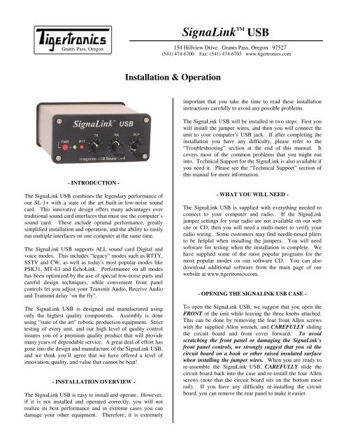
- INTRODUCTION -<br />
<strong>The</strong> <strong>SignaLink</strong> <strong>USB</strong> combines the legendary per<strong>for</strong>mance of<br />
our SL-1+ with a state of the art built-in low-noise sound<br />
card. This innovative design offers many advantages over<br />
traditional sound card <strong>interface</strong>s that must use the computer’s<br />
sound card. <strong>The</strong>se include optimal per<strong>for</strong>mance, greatly<br />
simplified installation and operation, and the ability to easily<br />
run multiple <strong>interface</strong>s on one computer at the same time.<br />
<strong>The</strong> <strong>SignaLink</strong> <strong>USB</strong> supports ALL sound card Digital and<br />
voice <strong>modes</strong>. This includes “legacy” <strong>modes</strong> such as RTTY,<br />
SSTV and CW, as well as today's most popular <strong>modes</strong> like<br />
PSK31, MT-63 and EchoLink. Per<strong>for</strong>mance on all <strong>modes</strong><br />
has been optimized by the use of special low-noise parts and<br />
careful design techniques, while convenient front panel<br />
controls let you adjust your Transmit Audio, Receive Audio<br />
and Transmit delay "on the fly".<br />
<strong>The</strong> <strong>SignaLink</strong> <strong>USB</strong> is designed and manufactured using<br />
only the highest quality components. Assembly is done<br />
using “state of the art” robotic production equipment. Strict<br />
testing of every unit, and our high level of quality control<br />
insures you of a premium quality product that will provide<br />
many years of dependable service. A great deal of ef<strong>for</strong>t has<br />
gone into the design and manufacture of the <strong>SignaLink</strong> <strong>USB</strong>,<br />
and we think you’ll agree that we have offered a level of<br />
innovation, quality, and value that cannot be beat!<br />
- INSTALLATION OVERVIEW -<br />
<strong>The</strong> <strong>SignaLink</strong> <strong>USB</strong> is easy to install and operate. However,<br />
if it is not installed and operated correctly, you will not<br />
realize its best per<strong>for</strong>mance and in extreme cases you can<br />
damage your other equipment. <strong>The</strong>re<strong>for</strong>e, it is extremely<br />
<strong>SignaLink</strong> TM<br />
<strong>USB</strong><br />
154 Hillview Drive Grants Pass, Oregon 97527<br />
(541) 474-6700 Fax: (541) 474-6703 www.tigertronics.com<br />
Installation & Operation<br />
important that you take the time to read these installation<br />
instructions carefully to avoid any possible problems.<br />
<strong>The</strong> <strong>SignaLink</strong> <strong>USB</strong> will be installed in two steps. First you<br />
will install the jumper wires, and then you will connect the<br />
unit to your computer’s <strong>USB</strong> jack. If after completing the<br />
installation you have any difficulty, please refer to the<br />
“Troubleshooting” section at the end of this manual. It<br />
covers most of the common problems that you might run<br />
into. Technical Support <strong>for</strong> the <strong>SignaLink</strong> is also available if<br />
you need it. Please see the “Technical Support” section of<br />
this manual <strong>for</strong> more in<strong>for</strong>mation.<br />
- WHAT YOU WILL NEED -<br />
<strong>The</strong> <strong>SignaLink</strong> <strong>USB</strong> is supplied with everything needed to<br />
connect to your computer and radio. If the <strong>SignaLink</strong><br />
jumper settings <strong>for</strong> your radio are not available on our web<br />
site or CD, then you will need a multi-meter to verify your<br />
radio wiring. Some customers may find needle-nosed pliers<br />
to be helpful when installing the jumpers. You will need<br />
software <strong>for</strong> testing when the installation is complete. We<br />
have supplied some of the most popular programs <strong>for</strong> the<br />
most popular <strong>modes</strong> on our software CD. You can also<br />
download additional software from the main page of our<br />
website at www.tigertronics.com.<br />
- OPENING THE SIGNALINK <strong>USB</strong> CASE -<br />
To open the <strong>SignaLink</strong> <strong>USB</strong>, we suggest that you open the<br />
FRONT of the unit while leaving the three knobs attached.<br />
This can be done by removing the four front Allen screws<br />
with the supplied Allen wrench, and CAREFULLY sliding<br />
the circuit board and front cover <strong>for</strong>ward. To avoid<br />
scratching the front panel or damaging the <strong>SignaLink</strong>’s<br />
front panel controls, we strongly suggest that you sit the<br />
circuit board on a book or other raised insulated surface<br />
when installing the jumper wires. When you are ready to<br />
re-assemble the <strong>SignaLink</strong> <strong>USB</strong>, CAREFULLY slide the<br />
circuit board back into the case and re-install the four Allen<br />
screws (note that the circuit board sits on the bottom most<br />
rail). If you have any difficulty re-installing the circuit<br />
board, you can remove the rear panel to make it easier.
- CONNECTING THE RADIO -<br />
CAUTION – Be<strong>for</strong>e connecting the <strong>SignaLink</strong> to your<br />
radio, read this entire section thoroughly. Both the<br />
<strong>SignaLink</strong> and your radio can be damaged by improper<br />
installation. If you have already attached the <strong>SignaLink</strong> to<br />
your computer, then you will need to unplug the <strong>USB</strong> cable<br />
BEFORE installing the jumper wires.<br />
<strong>The</strong> <strong>SignaLink</strong> <strong>USB</strong> attaches to the radio through an 8-pin<br />
RJ-45 connector located on the rear of the unit. A radio<br />
cable with the appropriate connector <strong>for</strong> your radio was<br />
supplied with the <strong>SignaLink</strong> <strong>USB</strong> <strong>for</strong> this purpose. One end<br />
of this cable plugs into the <strong>SignaLink</strong>’s “RADIO” connector,<br />
and the other end plugs into the radio’s Mic, Data, or<br />
Accessory Port connector. This cable brings all of the<br />
required radio lines into the <strong>SignaLink</strong> <strong>USB</strong>, so that each<br />
signal can be connected to the appropriate matching line<br />
inside the <strong>SignaLink</strong>.<br />
<strong>The</strong> <strong>SignaLink</strong> <strong>USB</strong> uses the radio’s Ground, PTT, Speaker<br />
and Mic lines. Because the location of these signals on the<br />
radio connector varies from radio to radio, we have provided<br />
a “Programming Socket” inside the <strong>SignaLink</strong> (see JP-1 in<br />
Figure-4). <strong>The</strong> Programming Socket provides a convenient<br />
way to route the various signals to the correct pin on the<br />
radio connector. This is accomplished with “press-in”<br />
jumper wires so that no soldering is required.<br />
Jumper settings <strong>for</strong> most common radios are provided on the<br />
<strong>SignaLink</strong> CD and on our web site. Some of our radio<br />
cables also include the jumper settings with the cable. If<br />
jumper settings were supplied with your radio cable, then<br />
you can skip to the “Install Jumper Wires” section below,<br />
and install the jumpers as shown on that document. If you<br />
did not receive printed jumper settings with your cable, then<br />
please check the “Jumper Settings” section of the <strong>SignaLink</strong><br />
CD, or our web site. If you find the settings <strong>for</strong> your radio<br />
listed there (please be certain that you are looking at the<br />
jumper settings <strong>for</strong> the correct radio model and cable!),<br />
then skip to the “Install Jumpers Wires” section below and<br />
install the jumpers as shown. If we do not have the jumper<br />
settings <strong>for</strong> your radio available, then you will need to follow<br />
the “Detailed Jumper Installation Procedure” near the end of<br />
this manual, or contact Technical Support <strong>for</strong> assistance.<br />
Install Jumper Wires<br />
NOTE: <strong>The</strong> <strong>SignaLink</strong> <strong>USB</strong> NEVER needs external power,<br />
so socket JP-1 does NOT have a “PWR” pin like earlier<br />
<strong>SignaLink</strong> models. You can disregard the “PWR” jumper<br />
when installing the jumpers <strong>for</strong> the <strong>SignaLink</strong> <strong>USB</strong>. All<br />
other jumpers should be installed as shown.<br />
We have provided pre-stripped jumper wires with the<br />
<strong>SignaLink</strong> <strong>USB</strong>. <strong>The</strong>se wires are 24ga AWG and fit<br />
perfectly in the <strong>SignaLink</strong>’s jumper socket. If you use any<br />
other wire to install the jumpers, then this wire MUST be<br />
24ga AWG, or you will damage the <strong>SignaLink</strong>’s socket.<br />
Installation of the jumper wires can be done without any<br />
tools, but you may find it easier to do with needle-nosed<br />
2<br />
pliers. If you do use needle-nosed pliers, be sure to grip the<br />
wire close to the end that you are installing in the socket.<br />
When pushing the wires into the socket, be very careful not<br />
to bend them back and <strong>for</strong>th or they might break. <strong>The</strong> wires<br />
are quite durable and can be re-installed many times if you<br />
are careful, but if you break a wire off in the socket, there is<br />
no way to remove it. You will have to have a new socket<br />
installed! This should not be an issue if you are just a little<br />
bit careful.<br />
Once you have all of the jumpers installed, please take a few<br />
minutes to look them over. You should have the “SPKR”<br />
jumper installed only if you have Speaker/RX audio<br />
available on the radio connector that you are using. If this<br />
signal isn’t available (this is a possibility with Mic jacks),<br />
then this jumper should not be installed. Instead, you will<br />
need to connect the provided mono cable from the External<br />
Speaker or Headphone jack of your radio, to the SPKR jack<br />
on the rear panel of the <strong>SignaLink</strong> <strong>USB</strong>. This will pass the<br />
radio’s Speaker Audio signal into the <strong>SignaLink</strong>. Once you<br />
are confident that the jumpers are installed correctly, you can<br />
put the <strong>SignaLink</strong> <strong>USB</strong> circuit board back into the case (see<br />
“Opening <strong>The</strong> <strong>SignaLink</strong> Case” at the beginning of this<br />
manual).<br />
- AUXILIARY AUDIO OUTPUT -<br />
<strong>The</strong> <strong>SignaLink</strong> <strong>USB</strong> has an Auxiliary Audio jack (“Aux”) on<br />
the rear panel that can be used to attach an external radio<br />
speaker, or headphones <strong>for</strong> monitoring receiver audio. This<br />
especially useful if your radio’s built-in speaker has been<br />
cut-off by a speaker/headphone connection to the <strong>SignaLink</strong>.<br />
Note that the Aux jack can only be used with a<br />
speaker/headphones if the <strong>SignaLink</strong> <strong>USB</strong> is connected to<br />
high-level Speaker audio. If the <strong>SignaLink</strong> <strong>USB</strong> is<br />
connected to your radio’s Data or Accessory Port, then you<br />
will not be able to use this output <strong>for</strong> monitoring because<br />
virtually all of these ports have low-level outputs.<br />
NOTE: Attaching or removing an external speaker while<br />
you are using the <strong>SignaLink</strong> <strong>USB</strong> will change the loading on<br />
the radio’s speaker circuit. This will probably cause a<br />
change in the level of audio going to the <strong>SignaLink</strong> <strong>USB</strong>,<br />
and may require you to re-adjust the <strong>SignaLink</strong>’s RX level<br />
control or the radio’s Volume control to compensate.<br />
- TRANSMIT AUDIO MONITOR OUTPUT -<br />
<strong>The</strong> <strong>SignaLink</strong> <strong>USB</strong> has a Transmit Audio Monitor jack<br />
(“Mon”) on the rear panel that can be used with amplified<br />
speakers or high-impedance headphones to monitor the<br />
<strong>SignaLink</strong>’s Transmit Audio signal. <strong>The</strong> output level of this<br />
jack varies with the computer’s software volume controls,<br />
and provides a maximum level of approximately 400mv p-p<br />
into 1Kohm. This is sufficient to drive most amplified<br />
speakers and high-impedance headphones, but not unamplified<br />
speakers.<br />
NOTE: <strong>The</strong> Monitor output is NOT isolated from the<br />
computer, so it may be possible to hear low-level power
supply hum or noise generated by the computer or amplified<br />
speakers. This is normal and is NOT an indication that your<br />
Transmit Audio is noisy. <strong>The</strong> actual Transmit Audio signal<br />
going to the radio is FULLY ISOLATED from the computer<br />
and noise free.<br />
- CONNECTING THE COMPUTER -<br />
IMPORTANT: You should connect the <strong>SignaLink</strong> <strong>USB</strong> to<br />
your computer only AFTER you have installed the jumper<br />
wires. If you are running Windows 98, you will need to have<br />
your Windows Installation CD available when you connect<br />
the <strong>SignaLink</strong> <strong>USB</strong> to the computer.<br />
<strong>The</strong> <strong>SignaLink</strong> <strong>USB</strong> can be connected to any standard <strong>USB</strong><br />
1.1 or <strong>USB</strong> 2.0 jack on your computer. We have provided a<br />
standard <strong>USB</strong> cable <strong>for</strong> this purpose. Be<strong>for</strong>e attaching the<br />
<strong>USB</strong> cable, your computer should be turned ON, and<br />
Windows (or another supported Operating System) should<br />
be running. All communications programs and other<br />
software should be closed.<br />
We suggest that you plug the computer-end of the <strong>USB</strong> cable<br />
into the computer first, as this will help drain any static<br />
electricity off of you, and minimize the chance of static<br />
damage to the <strong>SignaLink</strong>. <strong>The</strong> computer end of the <strong>USB</strong><br />
cable has a flat rectangular shaped “A” type plug and will fit<br />
into the <strong>USB</strong> jack only one way. If it doesn’t plug in, then<br />
you either have turned it the wrong way, or you are trying to<br />
plug it into a non-<strong>USB</strong> jack. <strong>The</strong> <strong>SignaLink</strong> side of the cable<br />
can be plugged in after the connection to the computer has<br />
been made. This end of the cable has a <strong>USB</strong> “B” type<br />
connector installed and plugs into the <strong>SignaLink</strong>’s rear panel<br />
“<strong>USB</strong>” jack. This connector is also “keyed” and will only fit<br />
one way.<br />
When the <strong>USB</strong> connection between the <strong>SignaLink</strong> and the<br />
computer is complete, Windows (or other supported<br />
Operating System) will automatically detect and install the<br />
required drivers. You should see several “New Hardware<br />
Found” messages as the drivers are installed. Your<br />
installation CD will not be needed unless you running<br />
Windows 98. If you are running Windows 98, then you<br />
MUST have your Installation CD available, or you will not<br />
be able to install the <strong>SignaLink</strong> <strong>USB</strong>.<br />
Once the <strong>SignaLink</strong> <strong>USB</strong> drivers have been installed (this<br />
typically takes less than a minute), your computer will<br />
display a message indicating that “Your new hardware is<br />
installed and ready to use”. <strong>The</strong> <strong>SignaLink</strong> <strong>USB</strong> is now<br />
ready <strong>for</strong> use, however we suggest that you take a few<br />
minutes to configure Windows and your communications<br />
program(s) to best use it. This is easy to do and is described<br />
below in the “Sound Card Selection” section.<br />
NOTE: If you move the <strong>SignaLink</strong> <strong>USB</strong> to a different <strong>USB</strong><br />
port, Windows will detect this and re-install the <strong>SignaLink</strong><br />
<strong>USB</strong> drivers <strong>for</strong> the new port. Windows will do this one time<br />
<strong>for</strong> each different <strong>USB</strong> port that you use.<br />
3<br />
- SOUND CARD SELECTION -<br />
Because the <strong>SignaLink</strong> <strong>USB</strong> has its own built-in sound card,<br />
you will want to configure Windows to play its “System”<br />
sounds through your computer’s sound card instead of the<br />
<strong>SignaLink</strong> <strong>USB</strong>. Your communications program can then be<br />
configured to use only the <strong>SignaLink</strong> <strong>USB</strong>. This will<br />
eliminate any unwanted sounds from being transmitted<br />
accidentally, and allow your computer’s sound card and<br />
speakers to function as they normally would.<br />
To configure Windows, follow the steps below. If you are<br />
using a different operating system, then please contact our<br />
Technical Support Staff <strong>for</strong> assistance (See the Technical<br />
Support section of this manual).<br />
• Click the “Start” button and select “Control Panel”<br />
• Double-click the “Sounds and Audio Devices”<br />
icon.<br />
• A “Sounds and Audio Devices Properties” window<br />
will open. This window will look similar to the<br />
one shown below in Figure 1.<br />
Figure 1 - Sound and Audio Devices Properties<br />
• Click the “Audio” tab.<br />
• Under “Sound Playback” and “Sound Recording”,<br />
select your computer’s soundcard as the “Default<br />
Device”. <strong>The</strong> exact name of your computer’s<br />
soundcard will vary, but unless you have more than<br />
one sound card installed, you will only see the<br />
computer’s sound card and the <strong>SignaLink</strong>’s sound<br />
card listed (“<strong>USB</strong> Audio Codec”). Click the OK<br />
button and close the Control Panel.
• Your computer is now configured to send all system<br />
sounds to your computer’s sound card and speakers<br />
(see the important note below).<br />
NOTE: If your computer is used only <strong>for</strong> Amateur Radio<br />
Operation, then you might want to select the <strong>SignaLink</strong> <strong>USB</strong><br />
(“<strong>USB</strong> Audio Codec”) as your default sound card. This will<br />
<strong>for</strong>ce all programs (communications and otherwise) to<br />
always use the <strong>SignaLink</strong> <strong>USB</strong>. This can also be done if you<br />
are using an old sound card program that won’t let you select<br />
the sound card that you want to use. If you do select the<br />
<strong>SignaLink</strong> <strong>USB</strong>’s built-in sound card as the default card,<br />
then we suggest that you disable all Windows system sounds.<br />
- SETTING THE AUDIO LEVELS -<br />
<strong>The</strong> <strong>SignaLink</strong> <strong>USB</strong>’s built-in sound card provides the same<br />
consistent audio levels no matter what computer you are<br />
using, so the software audio level setting procedure has been<br />
greatly simplified. Be<strong>for</strong>e you operate your <strong>SignaLink</strong> <strong>USB</strong><br />
on the air, you will need to adjust the PLAYBACK software<br />
volume controls, and the <strong>SignaLink</strong>’s TX and RX level<br />
controls. Note that the <strong>SignaLink</strong> <strong>USB</strong> does NOT use<br />
software RECORDING controls (“waterfall drive”, etc.), so<br />
you will not need to worry about adjusting those.<br />
Adjustment of the Receive Audio is done completely by the<br />
<strong>SignaLink</strong>’s RX level control.<br />
While most levels are not too critical, incorrect adjustment of<br />
any of these levels can cause poor per<strong>for</strong>mance or unreliable<br />
operation. This procedure tells you how the levels should be<br />
set.<br />
Preliminary Setup<br />
• Be<strong>for</strong>e you can adjust the audio levels, the <strong>SignaLink</strong><br />
<strong>USB</strong> must be connected to the computer and radio.<br />
Both the <strong>SignaLink</strong> <strong>USB</strong> and the radio should be<br />
powered ON and a communications program that you<br />
have selected should already be installed on your<br />
computer. Note that you will be using the<br />
communications program to generate the audio tones<br />
that are used to adjust the level controls, so CW<br />
programs should NOT be used unless they have a<br />
continuous "Tune" mode. A PSK-31 program like<br />
DigiPan is ideal <strong>for</strong> making these adjustments.<br />
• Set the <strong>SignaLink</strong> <strong>USB</strong>’s TX level control to minimum<br />
(fully counter-clockwise), and the RX level control to<br />
50%. <strong>The</strong> Delay (“DLY”) control can be set to<br />
minimum <strong>for</strong> now.<br />
• Start your communications program and verify that the<br />
sound card selected <strong>for</strong> both Transmit and Receive is<br />
“<strong>USB</strong> Audio Codec” (this is the sound card name used<br />
by the <strong>SignaLink</strong> <strong>USB</strong>). Most programs allow you to<br />
select the sound card that you want to use in their<br />
“Configure” or “Setup” menu. Once selected, you<br />
should not need to select the <strong>SignaLink</strong> <strong>USB</strong> again, as<br />
long as it is plugged in be<strong>for</strong>e starting the program.<br />
4<br />
Radio Setup<br />
CAUTION – Be sure that your radio is connected to an<br />
antenna or dummy load be<strong>for</strong>e proceeding.<br />
• If you already know how to configure your radio <strong>for</strong><br />
<strong>digital</strong> operation, then you can skip to the “Transmit<br />
Audio Adjustment” section below.<br />
• If the <strong>SignaLink</strong> <strong>USB</strong> is connected to your radio’s Mic<br />
jack, then set your radio to “<strong>USB</strong>” mode (note that you<br />
can change this later if the mode you want to run<br />
requires LSB).<br />
• If the <strong>SignaLink</strong> <strong>USB</strong> is connected to a Data or<br />
Accessory Port, then you will need to set your radio to<br />
the appropriate mode <strong>for</strong> this type of connection. <strong>USB</strong><br />
will work on most radios, but you may need to select a<br />
special mode such as “Data”, “User”, or “D-<strong>USB</strong>”. If<br />
you are not sure which mode to use, then consult your<br />
radio manual.<br />
• Set the radio’s Mic Gain control to 50%. Note that if the<br />
<strong>SignaLink</strong> is connected to a Data or Accessory Port, this<br />
control may not have any effect on power output.<br />
• Set your radio’s “Forward Power” control to provide<br />
maximum power (this will be adjusted later to bring the<br />
power down to a suitable level). Note that the “Forward<br />
Power” control might be labeled “RF Power” or<br />
“Carrier Power” on your radio. Newer radios will have<br />
an “RF Power” menu setting instead of a knob.<br />
• Your radio’s Speech Processor / Compressor and VOX<br />
features should be turned OFF.<br />
Transmit Audio Adjustment<br />
• Open the Windows Volume Control Panel by clicking<br />
on the Start Button and selecting Programs (or “All<br />
Programs”), Accessories, Multimedia (or<br />
“Entertainment”), and then Volume Control.<br />
• From the Options menu, select Properties to display the<br />
Properties page.<br />
• In the “Mixer Device” drop-down menu, verify that<br />
“<strong>USB</strong> Audio CODEC” is selected. This is the name /<br />
identifier used by the <strong>SignaLink</strong> <strong>USB</strong>’s built-in sound<br />
card, so this MUST be selected.<br />
• In the “Adjust Volume For” window, select Playback.<br />
• In the “Show the Following Volume Controls” window,<br />
verify that the Speaker and Wave controls are checked.<br />
Other controls can also be checked but they will not be<br />
used.<br />
• <strong>The</strong> Properties window should now look like the one<br />
shown below in Figure 2. Verify that it does and then<br />
click OK.
Figure 2 –Properties Window<br />
• <strong>The</strong> volume control panel will now open. Set the<br />
“Speaker” control (far left control) to 100% max<br />
volume, and set the “Wave” control to 50%. Note that<br />
the Speaker and Wave controls should NOT be muted.<br />
All other controls can be. Your volume control panel<br />
should now look similar to the one shown below in<br />
Figure 3:<br />
Figure 3 –Volume Control Panel<br />
• <strong>The</strong> <strong>SignaLink</strong>’s software volume controls are now set<br />
to provide an audio level that is suitable <strong>for</strong> most radios.<br />
If you determine that you need more audio (complete<br />
this procedure first!), then you can increase the “Wave”<br />
control. A special jumper can also be installed inside<br />
the <strong>SignaLink</strong> <strong>USB</strong> to provide even more audio (see the<br />
“Special Jumpers” section of this manual)<br />
• Select “TUNE” in your communications program. <strong>The</strong><br />
<strong>SignaLink</strong>’s PTT LED should now be ON, and your<br />
radio should be transmitting. If the PTT LED is not<br />
5<br />
ON, then you may have the wrong sound card selected<br />
in your communications program or the volume control<br />
panel. If you cannot get the PTT LED to turn ON, then<br />
see the Troubleshooting section at the end of this<br />
manual.<br />
• You should now be able to adjust the <strong>SignaLink</strong> <strong>USB</strong>’s<br />
“TX” level control <strong>for</strong> the desired Transmit power level<br />
(see important note below). If you cannot get adequate<br />
power, then see the notes on jumper JP3 under the<br />
“Special Jumpers” section of this manual. If the<br />
problem still persists, then please see the<br />
Troubleshooting section at the end of the manual.<br />
• Be sure to turn your program’s “TUNE” function OFF<br />
when you are finished making adjustments!<br />
IMPORTANT: We strongly suggest that you consult your<br />
radio manual to verify the manufacturers recommended<br />
maximum transmit level and duty cycle. Most <strong>digital</strong> <strong>modes</strong><br />
are 100% duty cycle and cannot be run at full power without<br />
damaging your radio. Also, some <strong>modes</strong> (like PSK-31)<br />
typically only require 25 watts or less <strong>for</strong> reliable<br />
communication. You can actually “swamp” out other users<br />
if you use too much power.<br />
Receive Audio Adjustment<br />
• <strong>The</strong> <strong>SignaLink</strong> <strong>USB</strong> does not use software<br />
“RECORDING” controls, so all adjustment of the<br />
Receive Audio level is done with the unit’s front-panel<br />
“RX” level control. A setting of 50% is usually about<br />
right <strong>for</strong> most installations, but you can adjust this<br />
control up or down as necessary.<br />
• If you find that you have too much Receive Audio, or<br />
not enough, then you may need to adjust your radio’s<br />
Volume control (or fixed level “AF Output” control, if<br />
using a Data Port or Accessory Port). Jumper JP2 can<br />
also be installed inside the <strong>SignaLink</strong> to increase the<br />
Receive Audio level (see the “Special Jumpers” section<br />
of this manual <strong>for</strong> details).<br />
• If you cannot resolve the Receive problem, then please<br />
see the Troubleshooting section at the end of this<br />
manual.<br />
- GENERAL RADIO SETTINGS -<br />
Virtually all <strong>digital</strong> <strong>modes</strong> require that you TURN OFF any<br />
Speech Processing or Compression features in your radio.<br />
This is to insure RF linearity. You must also TURN OFF<br />
your VOX circuit when using the <strong>SignaLink</strong>. As mentioned<br />
in the audio level setting procedure, you can usually use your<br />
radio’s <strong>USB</strong> mode <strong>for</strong> <strong>digital</strong> operation (LSB <strong>for</strong> some<br />
bands). However, if the <strong>SignaLink</strong> <strong>USB</strong> is connected to a<br />
Data or Accessory Port, then you may need to select a<br />
special mode such as “Data”, “User”, “D-<strong>USB</strong>” or “D-LSB”<br />
(to name a few). If you are not sure which mode to use, then<br />
consult your radio manual.
- SIGNALINK CONTROLS AND INDICATORS -<br />
Power Switch – This turns power OFF to the <strong>SignaLink</strong><br />
<strong>USB</strong>’s Transmit and Receive circuits, but it does not power<br />
down the built-in sound card. <strong>The</strong> <strong>SignaLink</strong> <strong>USB</strong>’s sound<br />
card will power down with the computer automatically when<br />
the computer is shutdown, or put into “suspend” mode.<br />
When you are not using the <strong>SignaLink</strong>, we suggest that you<br />
turn it OFF.<br />
Power LED – This LED will be ON when the computer is<br />
powered up and the <strong>SignaLink</strong>’s “Power” switch is<br />
depressed. If the computer enters “suspend” mode and shuts<br />
off power to the <strong>USB</strong> port, then this LED will turn OFF even<br />
if the <strong>SignaLink</strong>’s Power switch is turned ON.<br />
PTT LED – This LED is ON only when the <strong>SignaLink</strong> <strong>USB</strong><br />
is transmitting.<br />
TX Control – This control adjusts the Transmit Audio level<br />
going to the radio, which directly affects the radio’s RF<br />
power output level. Turn this control clockwise <strong>for</strong> more<br />
power, and counter-clockwise <strong>for</strong> less.<br />
RX Control – This control adjusts the Receive Audio level<br />
(sometimes called “Waterfall Drive”) going into the<br />
computer. Turn this control clockwise <strong>for</strong> more audio and<br />
counter-clockwise <strong>for</strong> less.<br />
DLY Control – This control adjusts the Transmit “Hang<br />
Time” <strong>for</strong> the <strong>SignaLink</strong> <strong>USB</strong>’s Auto-PTT TM circuit. With<br />
the control set to minimum (fully counter-clockwise), the<br />
radio will remain keyed <strong>for</strong> approximately 15 milliseconds<br />
after Transmit Audio has stopped. This setting is suitable <strong>for</strong><br />
<strong>modes</strong> that require fast turn-around times like Packet. It is<br />
also the best position <strong>for</strong> many other <strong>digital</strong> <strong>modes</strong> like PSK-<br />
31 and MT63. A longer delay of up to 4 seconds can be<br />
selected by turning the control clock-wise. A delay of<br />
approximately two seconds is adequate <strong>for</strong> most Voice<br />
<strong>modes</strong> such as EchoLink. For slow AFSK CW, you will<br />
probably want to set the Hang Time delay to between 500 ms<br />
and 1 second.<br />
- SPECIAL JUMPERS -<br />
<strong>The</strong> <strong>SignaLink</strong> has three jumpers that can be installed to<br />
provide higher Transmit and Receive Audio levels, and<br />
increase the unit’s PTT sensitivity. <strong>The</strong>se jumpers are<br />
described below and their location is shown in Figure 4.<br />
JP2 – This jumper can be installed to increase the Receive<br />
Audio signal going into the <strong>SignaLink</strong> <strong>USB</strong>’s built-in sound<br />
card.<br />
JP3 – This jumper can be installed to increase the <strong>SignaLink</strong><br />
<strong>USB</strong>’s Transmit Audio Signal. With this jumper installed,<br />
the <strong>SignaLink</strong> <strong>USB</strong> can provide up to 2Vp-p into 600 ohms.<br />
This should be more than adequate to drive any radio to full<br />
power. Note that this is NOT needed <strong>for</strong> most radios.<br />
6<br />
JP4 – This jumper can be installed to increase the sensitivity<br />
of the <strong>SignaLink</strong> <strong>USB</strong>’s Auto-PTT TM circuit approximately<br />
two times. This is not necessary <strong>for</strong> Data <strong>modes</strong>, but does<br />
offer increased per<strong>for</strong>mance <strong>for</strong> voice applications.<br />
Figure 4 – Location of jumpers JP2, JP3 and JP4.<br />
- VISIT US ON THE INTERNET -<br />
If you have Internet access, please visit our web site at:<br />
http://www.tigertronics.com<br />
Our site contains the latest news about <strong>Tigertronics</strong>’<br />
products, support in<strong>for</strong>mation, and other in<strong>for</strong>mation of<br />
interest to all Hams and SWLs. This is also the best source<br />
<strong>for</strong> downloadable programs that work with our products. We<br />
also have all of our distribution software and documentation<br />
available <strong>for</strong> download as well. <strong>The</strong> site is updated often, so<br />
stop in on a regular basis and get the latest news and updates.<br />
- YOUR COMMENTS WELCOME -<br />
We have made every ef<strong>for</strong>t to make the <strong>SignaLink</strong> <strong>USB</strong> the<br />
best product possible. We welcome any comments or<br />
suggestions that you would like to make. Please drop us a<br />
note to let us know about your experiences, tips you would<br />
like to share with other users, or how we might do a better<br />
job <strong>for</strong> you.<br />
- LIMITED WARRANTY -<br />
<strong>Tigertronics</strong> warrants the <strong>SignaLink</strong> <strong>USB</strong> to be free of<br />
defects in material and workmanship <strong>for</strong> a period of 90 days<br />
from the date of shipment. <strong>Tigertronics</strong> will repair or<br />
replace, at its option, any parts found to be defective during<br />
the warranty period. This warranty does not include any unit<br />
that has been subject to misuse, neglect, improper<br />
installation or operation. This warranty is in lieu of all
others, express or implied, and no person or representative is<br />
authorized to assume <strong>for</strong> <strong>Tigertronics</strong> any other liability in<br />
connection with the sale or use of this product. <strong>Tigertronics</strong><br />
will not be responsible <strong>for</strong> any expense or loss of revenue or<br />
property incurred by the user due to operation or malfunction<br />
of this equipment. <strong>Tigertronics</strong> reserves the right to make<br />
any changes including but not limited to the circuit,<br />
components or firmware, or to incorporate new features, at<br />
any time, without obligation.<br />
- RETURN POLICY -<br />
A Return Material Authorization Number (RMA#) must be<br />
obtained be<strong>for</strong>e any product will be accepted <strong>for</strong> return or<br />
repair. Items received without an RMA# clearly marked on<br />
the OUTSIDE of the package WILL BE REFUSED. Items<br />
being returned must be sent prepaid. Returned items should<br />
have a note attached showing the RMA#, customer name,<br />
return address, phone number, and action requested. Units<br />
being returned <strong>for</strong> warranty repair must be accompanied by a<br />
copy of the original sales invoice showing the date of<br />
purchase.<br />
Customers wishing to return a product <strong>for</strong> REFUND, <strong>for</strong><br />
ANY REASON, must receive an RMA# within 15 days from<br />
the shipping date shown on the original sales invoice.<br />
Customers returning products <strong>for</strong> refund will be charged a<br />
Restocking Fee equal to 20% of the purchase price, to cover<br />
the cost of re-testing and re-stocking. Products that have<br />
been damaged or modified in any way may not be returned.<br />
Contact our Technical Support department <strong>for</strong> the RMA#.<br />
- TECHNICAL SUPPORT -<br />
BEFORE YOU CALL – <strong>The</strong> vast majority of technical<br />
issues can be resolved with the in<strong>for</strong>mation that is available<br />
in this manual and on the <strong>Tigertronics</strong> web site. If you<br />
thoroughly investigate these resources, you will probably<br />
never need to call. Please take some time to read through<br />
this manual, and then check the online support resources to<br />
be sure that you have the most current software and<br />
documentation available. Thank you.<br />
If you encounter a problem that you cannot resolve with the<br />
<strong>SignaLink</strong> (not software), please contact our Technical<br />
Support Staff at (541) 862-2639. <strong>The</strong>y are available every<br />
Monday, Wednesday, and Friday, from 1:00 PM to 5:00<br />
PM Pacific Time. Be sure to have your equipment available<br />
<strong>for</strong> testing when you call. Please DO NOT mail, email, or<br />
fax your technical inquiries. We realize that calling is a little<br />
more expensive, but more can be accomplished in a few<br />
minutes on the phone than can be done in hours of writing!<br />
- FCC STATEMENT -<br />
NOTE: This equipment has been tested and found to comply<br />
with the limits <strong>for</strong> a Class B <strong>digital</strong> device, pursuant to Part<br />
15 of the FCC Rules. <strong>The</strong>se limits are designed to provide<br />
7<br />
reasonable protection against harmful interference in a<br />
residential installation. This equipment generates, uses and<br />
can radiate radio frequency energy and, if not installed and<br />
used in accordance with the instructions, may cause harmful<br />
interference to radio communications. However, there is no<br />
guarantee that interference will not occur in a particular<br />
installation. If this equipment does cause harmful<br />
interference to radio or television reception, which can be<br />
determined by turning the equipment off and on, the user is<br />
encouraged to try to correct the interference by one of the<br />
following measures:<br />
• Reorient or relocate the receiving antenna.<br />
• Increase the separation between the equipment and<br />
receiver.<br />
• Connect the equipment into an outlet on a circuit different<br />
from that to which the receiver is connected.<br />
• Consult the dealer or an experienced radio/TV technician<br />
<strong>for</strong> help.<br />
Caution: Changes or modifications not expressly approved<br />
by the party responsible <strong>for</strong> compliance could void the users<br />
authority to operate the equipment.<br />
- GENERAL SPECIFICATIONS -<br />
Freq Response: 100hz to 10Khz.<br />
Upper Frequency limit is<br />
Intentionally limited by a<br />
Low Pass Filter.<br />
Sampling Size/Rate: 16 Bit, All standard rates are<br />
supported up to 48Khz.<br />
Computer OS: Windows 98SE/ME/2000/XP<br />
MAC OS 9.1 or later<br />
MAC OS X 10.00 or later<br />
Radio In/Out Z: 600 Ohm (nom). TX/RX Levels<br />
are fully adjustable <strong>for</strong><br />
compatibility with Hi-Z and<br />
Low-Z radio connections.<br />
Auto-PTT Delay: Adjustable "Hang Time"<br />
30 ms to >3 seconds<br />
PTT Circuit: Relay, 90V 3AMP (max)<br />
Radio Connector: TX/RX Audio,PTT,GND - RJ-45<br />
RX Audio/Spkr - 3.5mm Mono<br />
Computer Connector: <strong>USB</strong> 1.1/2.0 Compatible<br />
Standard <strong>USB</strong> "A" type Conn.<br />
Other Connectors: Aux. Speaker - 3.5mm Mono<br />
Case: Extruded Aluminum - 6061T4<br />
Dimensions: 1.6" x 3.2" x 3.6"<br />
Operating Temp: -30C to +60C
If you do not find the jumper settings <strong>for</strong> your radio listed on<br />
the <strong>SignaLink</strong> CD or our web site, then follow this step-bystep<br />
guide to install the jumpers <strong>for</strong> your radio.<br />
Signal Lines - Every installation requires connecting the<br />
<strong>SignaLink</strong> to at least three pins on the radio’s Mic, Data, or<br />
Accessory connector. On the Mic connector these are “Mic<br />
Input”, “PTT”, and “Ground”. On the Data or Accessory<br />
Port, these same basic signals are used, but they are usually<br />
labeled differently. <strong>The</strong> table in Figure 1 shows the common<br />
Mic signals and their Data / Accessory port equivalents.<br />
Please refer to this table if you are installing the <strong>SignaLink</strong><br />
<strong>USB</strong> on your radio’s Data or Accessory port.<br />
Mic Signal Data/Accessory Port Signal<br />
PTT (Push-To-Talk) Standby, PKS, or Packet Standby<br />
Mic / Mic Input TX Data, Data Input, PKD, or<br />
Mod In<br />
AF Out / Speaker RX Data, Data Out, RXD, or<br />
RX Audio<br />
PTT GND PTT Ground, Chassis Ground<br />
Mic GND Signal GND, Mic GND<br />
Figure 1 - Data / Accessory Port Signal Names<br />
Note that many radios actually have multiple ground<br />
connections (Mic Ground, PTT Ground, etc.). <strong>The</strong><br />
Programming Socket has multiple ground (G) connections<br />
<strong>for</strong> this reason. On many radios the Mic, Data, and<br />
Accessory connectors also provide access to Speaker Audio.<br />
If Speaker Audio (or the equivalent Data / Accessory Port<br />
signal) is not available from the connector on your radio,<br />
then you will need to install the provided mono cable from<br />
the External Speaker or Headphone jack on your radio, to<br />
the SPKR jack on the rear panel of the <strong>SignaLink</strong> <strong>USB</strong>. If<br />
this signal is available on the connector, then you will<br />
connect it later in this section.<br />
Be<strong>for</strong>e proceeding with jumper installation you should verify<br />
in your radio manual that the radio PTT requirements do not<br />
exceed the specifications of the <strong>SignaLink</strong> keying circuit.<br />
Verify that the PTT is “Grounded” to make the radio<br />
transmit and the PTT signal does not exceed 3 Amps at 90V.<br />
This should be within the ratings of all modern radios but<br />
could be a problem on some older rigs. If your radio<br />
exceeds these specifications or requires some other keying<br />
arrangement, then you will need to key the radio using a low<br />
voltage/low current relay. Please feel free to contact<br />
Technical Support if you need assistance with this.<br />
Connectors With More Than Eight Pins – <strong>The</strong> jumper<br />
installation procedure in this manual is <strong>for</strong> use with radio<br />
connectors that have 8 pins or less. If you are installing the<br />
<strong>SignaLink</strong> on a 13-pin Accessory port (currently the only<br />
radio connector with more than eight pins), then you will<br />
either be using a fully assembled cable that we have<br />
provided, or you will be attaching your own 13-pin<br />
connector to our un-terminated cable. In either case, jumper<br />
Detailed Jumper Installation Procedure<br />
8<br />
settings and/or special instructions <strong>for</strong> installing the<br />
connector and jumpers were included with the radio cable.<br />
Please follow those instructions instead of the procedures in<br />
this manual.<br />
Identifying Jumper Locations - Identifying the jumper<br />
locations <strong>for</strong> your radio is a two-step process. First we will<br />
identify the pin-out <strong>for</strong> the radio connector, and then we will<br />
verify that it is correct. <strong>The</strong> verification process is very<br />
important since incorrect wiring could damage your<br />
equipment. <strong>The</strong> final steps will be to draw a wiring diagram<br />
using Figure-2 and actually install the jumpers.<br />
• Lookup Pin-out – In your radio Operators Manual, find<br />
the page that identifies the pin-out of the Mic, Data, or<br />
Accessory connector that you are going to use. Using<br />
the manual, identify the pin numbers assigned to the<br />
following signals, and record them below. Note that the<br />
signals found on radio Data and Accessory ports will<br />
likely be labeled differently from those shown. Please<br />
refer to the table in Figure 1 <strong>for</strong> the equivalent Data /<br />
Accessory Port signals.<br />
____ PTT<br />
____ Mic Input<br />
____ Speaker Audio**<br />
____ Mic Ground**<br />
____ PTT Ground**<br />
____ Chassis Ground**<br />
** Note that some radios only have one ground pin.<br />
** Speaker Audio is not always available.<br />
• Verify Pin-out – This step is Extremely Important<br />
since not all manufacturers use the same numbering<br />
convention <strong>for</strong> their connectors. This is especially true<br />
of radios using RJ-45 mic connectors. This brief<br />
verification process could ward off a major disaster<br />
when you turn on the power! This procedure verifies<br />
that the pin numbers, which you just identified in the<br />
Operators Manual, do in fact match the numbers<br />
identified on the Programming Socket. <strong>The</strong> easiest way<br />
to do this is to use a multimeter to verify some of the<br />
more important lines. Be<strong>for</strong>e you start, you will need to<br />
make sure that the radio power is OFF, that there are<br />
NO JUMPERS are installed in JP-1, and that the<br />
supplied cable is connected between the <strong>SignaLink</strong> and<br />
the radio.<br />
Note that you should not find the lines “scrambled”.<br />
<strong>The</strong>y will either be in the correct order or they will be<br />
completely reversed (pin 1=8, 2=7, 3=6, etc). First<br />
check the Ground pin (or pins) recorded earlier. You<br />
can do this by checking <strong>for</strong> continuity between the radio<br />
chassis and the pins numbered on the Programming<br />
Socket (JP-1). JP-1 is a very convenient place to probe<br />
since it is wired 1:1 to every pin on the radio connector.
You will be checking against the numbers you recorded<br />
earlier from the Operators Manual. Note that if your<br />
radio has a separate mic ground it may have a slight<br />
resistance to chassis ground. Any other ground pin<br />
should test very close to zero ohms. If you do not get<br />
the expected continuity in this test, try checking against<br />
the numbers in the reverse order (1=8, 2=7, 3=6, etc). It<br />
would probably be very helpful to make a new table<br />
using the reversed number sequence to avoid mistakes!<br />
This step should establish whether or not the radio<br />
connector is “reverse ordered” and allow you to correct<br />
the numbers on your table.<br />
Once you are confident about the ground lines you can<br />
move on to other pins. If your radio had Accessory<br />
Power you should be able to turn ON the radio and use<br />
your multimeter (volts scale) to test <strong>for</strong> power on the<br />
appropriate pin of JP-1. <strong>The</strong> <strong>SignaLink</strong> <strong>USB</strong> does NOT<br />
use power from the radio, but this line can still be used<br />
<strong>for</strong> verification purposes.<br />
You can test the PTT pin as follows: First check the pin<br />
with your multimeter (volts). You should see a voltage<br />
on the PTT pin (5-12v) when the radio is ON. You<br />
should be able to key the radio by grounding the PTT<br />
line. For the sake of safety, you should ground the PTT<br />
pin through a small value resistor (100-1000 ohms) in<br />
case it’s not the pin you think it is! Be sure your radio<br />
power is set to LOW and an antenna or dummy load is<br />
connected <strong>for</strong> this test, as the radio will go into<br />
“transmit” with the line grounded.<br />
If the Speaker signal is available on the connector you<br />
are using, then you can try attaching a speaker or<br />
headphone to the appropriate pin on JP-1 to see if you<br />
can hear audio. Note that you will NOT be able to hear<br />
anything if the speaker source is a low level output<br />
(usually the case on Data and Accessory ports). <strong>The</strong>re is<br />
no easy way to test the mic line but there will be little<br />
doubt about it if the other lines are correct. <strong>The</strong> main<br />
thing you are looking <strong>for</strong> here is to determine whether or<br />
not the connector numbers are reversed on your radio.<br />
If you have any unresolved errors, then you should<br />
double check your numbering in the Operators Manual<br />
again.<br />
G<br />
G<br />
G<br />
- - -<br />
- - -<br />
PTT<br />
MIC<br />
SPK<br />
JP1<br />
Radio Mic Connector<br />
8_______________________<br />
7_______________________<br />
6_______________________<br />
5_______________________<br />
4_______________________<br />
3_______________________<br />
2_______________________<br />
1_______________________<br />
Figure 2 – Jumper Wiring Diagram<br />
9<br />
• Draw Jumper Wires - Once you have verified your<br />
pin-out and are com<strong>for</strong>table with the results, you are<br />
ready to label the lines in Figure-2 and draw in the<br />
jumper wires. To do this, you simply need to draw a<br />
line between the pins on the left of JP-1 (G, PTT, Mic &<br />
SPKR) and their appropriate match on the right side of<br />
the diagram. For example, draw a line between the “G”<br />
pin on the left of JP-1 and the line that you labeled<br />
“Ground”. <strong>The</strong> “PTT” pin should be connected to the<br />
pin that you labeled “PTT” and so on. If you are<br />
installing the <strong>SignaLink</strong> on a Data or Accessory port,<br />
then refer to Figure 1 <strong>for</strong> the correct signal names. An<br />
example of the microphone Jumper Wiring Diagram <strong>for</strong><br />
a Kenwood TS-450 is shown in Figure 3.<br />
G<br />
G<br />
G<br />
- - -<br />
- - -<br />
PTT<br />
MIC<br />
SPKR<br />
JP1<br />
Radio Mic Connector<br />
8_______________________<br />
Ground<br />
7_______________________<br />
Mic Ground<br />
6_______________________<br />
Receive Audio<br />
5_______________________<br />
4_______________________<br />
3_______________________<br />
3_______________________<br />
2_______________________<br />
2_______________________<br />
Packet Standby (PTT)<br />
1_______________________<br />
Mic Input<br />
Figure 3 – Example Jumper Wire Diagram <strong>for</strong> TS-450 Mic<br />
VERY IMPORTANT NOTE! – You are about to install<br />
the jumper wires. <strong>The</strong> wires must be 24ga AWG or you<br />
will damage the socket! It would be best to use the<br />
wires that we provided <strong>for</strong> this purpose to avoid<br />
damage.<br />
Install Jumper Wires – Now that you know where the<br />
jumper wires go, all you need to do is install them!<br />
Installation of the jumper wires can be done without any<br />
tools, but you may find it easier to do with needle-nosed<br />
pliers. If you do use needle-nosed pliers, be sure to grip<br />
the wire close to the end that you are installing in the<br />
socket. When pushing the wires into the socket, be very<br />
careful not to bend them back and <strong>for</strong>th or they might<br />
break. If you break a wire off in the socket, there is no<br />
way to remove it. You will have to have a new socket<br />
installed! This should not be an issue if you are just a<br />
little bit careful.<br />
Once you have all of the jumpers installed, please take a<br />
few minutes to look them over. You should have the<br />
“SPKR” jumper installed only if you have Speaker/RX<br />
audio available on the radio connector that you are<br />
using. If this signal isn’t available (a possibility with<br />
Mic jacks), then this jumper should not be installed.<br />
Instead, you will need to install the provided mono cable<br />
from the External Speaker or Headphone jack of your
adio, to the SPKR jack on the rear panel of the<br />
<strong>SignaLink</strong> <strong>USB</strong>. This will pass the radio’s Speaker<br />
Audio signal into the <strong>SignaLink</strong> so that the unit can<br />
receive. Once you are confident that the jumpers are<br />
installed correctly, you can put the <strong>SignaLink</strong> <strong>USB</strong><br />
circuit board back into the case.<br />
10
If you do not find your problem listed here, or if you are<br />
unable to resolve the problem, then please refer to the<br />
Technical Support section of this manual <strong>for</strong> instructions on<br />
contacting our Technical Support Staff.<br />
Radio doesn’t transmit AND the <strong>SignaLink</strong> <strong>USB</strong>'s PTT<br />
LED is OFF - Check the following:<br />
• Verify that the <strong>SignaLink</strong> <strong>USB</strong>’s PWR LED is ON. If it<br />
is not, then check your <strong>USB</strong> cable connection to the<br />
computer and the <strong>SignaLink</strong>.<br />
• Verify that your communications program is configured<br />
to use the <strong>SignaLink</strong> <strong>USB</strong>’s built-in sound card. <strong>The</strong><br />
program should have “<strong>USB</strong> Audio CODEC” selected as<br />
the sound card <strong>for</strong> both Transmit and Receive.<br />
• Verify that the PLAYBACK volume controls <strong>for</strong> the<br />
<strong>SignaLink</strong> <strong>USB</strong> are set according to the “Setting <strong>The</strong><br />
Audio Levels” procedure. If they are too low, then the<br />
<strong>SignaLink</strong> <strong>USB</strong> will NOT transmit.<br />
Radio doesn’t transmit even though the <strong>SignaLink</strong>'s PTT<br />
LED is ON - If the <strong>SignaLink</strong> <strong>USB</strong>'s PTT LED turns ON but<br />
the radio doesn't switch to transmit, then you have most<br />
likely jumpered the PTT signal incorrectly on JP-1 (go back<br />
and double-check ALL jumpers). If the <strong>SignaLink</strong> is<br />
attached to your radio’s Data or Accessory Port, then another<br />
possible cause is that your radio isn’t configured properly to<br />
use that port. Consult your radio manual and verify that your<br />
radio is in the correct Mode (Digital <strong>USB</strong>, etc.).<br />
Radio transmits but there is no power output, or it is too<br />
low – <strong>The</strong> <strong>SignaLink</strong> <strong>USB</strong> can provide more than enough<br />
Transmit Audio to drive any radio to full power. If you have<br />
set the TX level control to maximum and still cannot get<br />
enough power, then check the following:<br />
• If you are using a CAT <strong>interface</strong> to control your radio,<br />
then you need to disable "PTT by CAT Control" (or<br />
similar option) in your communications software, so that<br />
the <strong>SignaLink</strong> can key the radio. This is necessary<br />
because some radio's will only look <strong>for</strong> Transmit Audio<br />
on the Mic jack if the radio is switched into Transmit by<br />
the CAT <strong>interface</strong>. Note that this is a design issue with<br />
the radio and has absolutely nothing to do with the<br />
<strong>SignaLink</strong>.<br />
• Verify that your radio’s “Forward Power” (sometimes<br />
called “RF Power” or “Carrier Power”) control is set to<br />
maximum.<br />
• If the <strong>SignaLink</strong> is attached to your radio’s Mic jack,<br />
then try turning up your radio’s Mic Gain control.<br />
Troubleshooting<br />
11<br />
• Adjust the Windows “Wave” PLAYBACK volume<br />
control higher.<br />
• See the “Special Jumpers” section of this manual and<br />
install JP3. This will dramatically increase the<br />
<strong>SignaLink</strong>’s Transmit Audio level. Note that this is<br />
NOT needed <strong>for</strong> most radios, so you really need to be<br />
sure that everything else is correct be<strong>for</strong>e doing this.<br />
• If the <strong>SignaLink</strong> is attached to a Kenwood 13-pin<br />
Accessory Port, then you may have set the PTT jumper<br />
incorrectly. Double-check the document that was<br />
supplied with your radio cable to see if your radio<br />
requires a standard PTT jumper or the diode module to<br />
be installed.<br />
Transmit signal is “wide” or distorted – This is generally<br />
the result of over-driving your radio. Verify that your<br />
radio’s speech processor/compressor is turned OFF. Your<br />
radio’s “Forward Power” control (sometimes called “RF<br />
Power” or “Carrier Power”) should be set to maximum. If<br />
you have lowered this control to decrease your transmit<br />
power, then you more than likely have not set the audio<br />
levels correctly, and are overdriving your radio. Follow the<br />
“Setting <strong>The</strong> Audio Levels” procedure to correct this<br />
problem. If the above mentioned radio controls are set<br />
correctly, then try turning the radio’s Mic, Data or Accy Port<br />
gain and see if that improves the quality of your signal<br />
(Data/Accy Port gain is usually a radio menu setting). If this<br />
has no effect, then you may have the software PlayBack<br />
volume controls, or the <strong>SignaLink</strong> <strong>USB</strong>’s TX level control<br />
set to high. See the “Setting <strong>The</strong> Audio Levels” procedure to<br />
correct this.<br />
<strong>The</strong> <strong>SignaLink</strong>’s TX control is near minimum but the<br />
Radio’s transmit power is too high – This is most likely<br />
because the radio’s Mic, Data or Accy Port gain control is<br />
set too high. If the <strong>SignaLink</strong> is attached to the Mic jack,<br />
then try turning the radio’s Mic Gain control down ( this may<br />
also affect Data/Accy Ports on some radios). If the<br />
<strong>SignaLink</strong> is attached to a Data or Accy Port, then your radio<br />
should have a menu setting or trimmer to adjust the gain.<br />
Note that some radios call the Data or Accy Port gain control<br />
“Packet Input Level” or “Packet Gain”. Contact Tech<br />
Support if you are unable to resolve this problem.<br />
I can't seem to receive - <strong>The</strong>re are several possible causes<br />
<strong>for</strong> this problem:<br />
• <strong>SignaLink</strong> <strong>USB</strong>’s RX level control or radio level<br />
control set too low – Verify that the <strong>SignaLink</strong>s RX<br />
level control is turned up (clockwise). If you are using<br />
Speaker Audio from the radio (not a fixed level signal<br />
from a Data/Accy Port), then verify that your radio<br />
volume is turned up. If your communications program<br />
doesn’t show any signs of Receive Audio (no waterfall<br />
display, etc.), then please review the “Connecting <strong>The</strong>
Radio” and "Setting <strong>The</strong> Audio Levels" sections of this<br />
manual.<br />
• Computer too slow or incompatible with software.<br />
Software not configured properly - Check the<br />
documentation <strong>for</strong> the program that you are using and<br />
verify that your computer meets the minimum<br />
requirements. Verify that the program is configured<br />
correctly (the <strong>SignaLink</strong> <strong>USB</strong>’s “<strong>USB</strong> Audio CODEC”<br />
should be selected as the sound card). If all else fails,<br />
try using a different program.<br />
Why Can't I Receive Some Stations - No matter how good<br />
your antenna and radio are, there will always be some<br />
stations that you cannot copy (even with strong signals!).<br />
While the reason <strong>for</strong> this may be because of operator error<br />
(wrong mode or baud rate, off frequency, etc.), radio wave<br />
propagation problems can often prevent you from receiving.<br />
Some <strong>modes</strong> are more susceptible to this than others. For<br />
example, even though PSK31 usually works very well with<br />
weak signals, sometimes even strong PSK31 signals cannot<br />
be copied at all because of multipath and Doppler Shift<br />
propagation problems. Other <strong>modes</strong> like HF Packet and<br />
RTTY do not work well with weak signals and are<br />
susceptible to multipath and Doppler Shift.<br />
Windows "System Sounds" cause the <strong>SignaLink</strong> to<br />
transmit – This will NOT happen if you configure Windows<br />
to use your computer’s sound card as the default sound card.<br />
See the “Connecting <strong>The</strong> Computer” section of this manual<br />
to resolve this problem.<br />
Adjusting the Windows Volume Control Panel has no<br />
effect – If this happens, then you are almost certainly<br />
adjusting the volume controls <strong>for</strong> the wrong sound card.<br />
Please go back to the “Setting <strong>The</strong> Audio Levels” procedure<br />
and pay careful attention to Figure 2, where “<strong>USB</strong> Audio<br />
Codec” is selected as the mixer device.<br />
12<br />
<strong>SignaLink</strong> and AutoPTT are trademarks of <strong>Tigertronics</strong><br />
Copyright © 2001-2007 <strong>Tigertronics</strong> - All Rights Reserved<br />
(6/1/07 Rev-D)