victrix 50 - RVR.ie
victrix 50 - RVR.ie
victrix 50 - RVR.ie

Create successful ePaper yourself
Turn your PDF publications into a flip-book with our unique Google optimized e-Paper software.
2<br />
Portrait of a market leader in a steady growth.<br />
Immergas is the leading company in the Italian market of gas heating boilers.<br />
In the headquarters of Brescello work more than 700 people, spread<br />
over an area of 45.000 sq.m. In 2006 Immergas sold about 3<strong>50</strong>.000 appliances;<br />
the turnover was 220 million euro, 52% of which on the international<br />
market.<br />
The range of products is continuously widening, in order to satisfy all market<br />
requests. At the moment Immergas offers more than 60 models, wall-mounted<br />
or floor standing, instantaneous, for outdoor installation, condensing,<br />
with sealed chamber. An extremely wide choice with a common characteristic:<br />
the research for reliability, long-life, conven<strong>ie</strong>nce.<br />
Immergas: now available in 30 countr<strong>ie</strong>s.<br />
Immergas presence on the international market has been increasing year<br />
after year. Today the brand is available in more than 30 countr<strong>ie</strong>s; the company<br />
structure includes 8 branches in Europe and one in China, as well as<br />
shares in significant import firms all around the world.<br />
Immergas is deeply investing in promotion and communication, with the aim<br />
of supporting the brand and penetrating new markets. From Asia to South<br />
America the company is steadily expanding, with a policy based on quality,<br />
vanguard products and accurate service.
Low emissions and eco-fr<strong>ie</strong>ndly products:<br />
Planet Earth says thanks.<br />
Condense and enjoy.<br />
Immergas pays great attention to nature and environment. Our<br />
Research and Development Department is more and more ecoor<strong>ie</strong>nted:<br />
this investment in terms of staff and resources is our<br />
contribution to make the world a cleaner space.<br />
When projecting new models, the search for energy saving is<br />
always the main issue, in order to reduce energy consumption<br />
and pollutant emissions. In Italy, Immergas is leader in the segment<br />
of condensing boilers, which offer up to 30% energy saving<br />
as compared to traditional ones.<br />
A condensing boiler is an eco-fr<strong>ie</strong>ndly boiler. The special burner allows to lower pollutant emissions such as carbon monoxide (CO)<br />
and nitrogen oxides (NOx), two of the main responsible of air pollution. In fact, condensing boilers belong to class 5, the most environment-fr<strong>ie</strong>ndly<br />
class established by the European standards (UNI EN 297 e UNI EN 483).<br />
Condensing boilers have an advanced modulating system which can perfectly adjust the heat output to the real needs of the heating<br />
system. The modulating range, wider than in traditional boilers, ensures the right comfort and wellness inside the house, in all different<br />
climatic situations throughout the year.<br />
3
4<br />
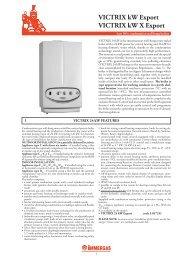
Power: from 10 up to 584 kW!<br />
VICTRIX 75 and VICTRIX <strong>50</strong> are wall-hung condensing boilers with respectively heat outputs of 72 and <strong>50</strong> kW, designed by Immergas<br />
to satisfy different kinds of installation exigenc<strong>ie</strong>s. The high effic<strong>ie</strong>ncy ratings ach<strong>ie</strong>ved are ideal when it comes to heating large volumes<br />
domestic systems (such as semi-detached houses or apartment blocks) and for commercial and industrial uses.<br />
VICTRIX 75 and VICTRIX <strong>50</strong> are heating only appliances, pre-engineered to operate both as single appliances or in cascade, with the<br />
advantage of providing a globally higher effic<strong>ie</strong>ncy at lower running costs.<br />
The wide modulation range characterizing the VICTRIX models and the possibility to manage up to a maximum of 8 appliances in<br />
cascade, allow to obtain great flexibility in the offer of the available heat outputs.<br />
Modulation range<br />
10 kW 584 kW
The cascade system<br />
The cascade system consists in the installation of two or more modular generators in parallel, connected to a control system regulating<br />
its functioning as if it was a single appliance. The total heat output is equal to the sum of the single generators outputs.<br />
Distributing the heat output on more than one unit brings many important advantages:<br />
• Higher effic<strong>ie</strong>ncy compared with the use of a single generator of great heat output, which would have to work with a reduced<br />
heating load for a good part of the heating period, with a consequent general lower effic<strong>ie</strong>ncy.<br />
• Less expenses thanks to the better effic<strong>ie</strong>ncy.<br />
• Greater safety as the subdivision in more units allows to maintain the heating function active even in case of maintenance on one<br />
of the connected appliances.<br />
• Greater flexibility with the possibility of distributing the heating request on all the appliances, while the functioning sequence<br />
avoids the fast deterioration of one boiler respect the others.<br />
Example of cascade functioning<br />
Minimum heat output Reduced heat output<br />
Medium heat output Maximum heat output<br />
5
6<br />
The thermoregulation system<br />
Boilers VICTRIX <strong>50</strong> and VICTRIX 75 are provided with new generation electronics, offering the best performances thanks to their regulation<br />
flexibility.<br />
In case of zones systems or cascade systems, it will be necessary to pre-arrange an adequate thermoregulation device able to manage<br />
every single appliance and elaborate the information from the system, in order to meet the most var<strong>ie</strong>d operating requirements.<br />
Immergas thermoregulation system is composed of:<br />
Cascade and zones regulator<br />
Zone manager<br />
Modulating room thermostat<br />
Cascade and zones regulator<br />
It is the central unit of the thermoregulation system. It allows to control, monitor and program<br />
the operating sequence of a maximum of 8 generators in cascade. The regulator controls<br />
the boiler’s delivery temperature adjusting it to the system requirements.<br />
The regulator can manage up to 3 different zones (2 of which at high/low temperature)<br />
and a sanitary circuit for a separate storage tank. It is also possible to install up to 5 regulators<br />
in parallel (of which only one, called master, will be connected to the generators) to<br />
control up to a maximum of 15 heating zones and 5 storage tanks for the domestic hot<br />
water production.<br />
Zone manager<br />
Connected to the cascade and zones regulator, it allows to keep the operating appliance<br />
and the heating system information handy and under control. This means that the previously<br />
set functioning parameters (turn on/off, temperatures, etc.) can be easily modif<strong>ie</strong>d by<br />
the user, without having to operate on the central regulator.<br />
Modulating room thermostat<br />
Connected to the cascade and zones regulator, it allows the user to regulate the room<br />
temperature of the single zones into which the system is divided.<br />
External probe<br />
Connected to the boiler, it allows to optimize the energy consumptions automatically<br />
adjusting the system delivery temperature to suit the outdoor temperature variations.<br />
System delivery probe<br />
It allows the cascade and zones regulator to manage the system temperature.<br />
Separate storage tank probe<br />
It allows the cascade and zones regulator to control the temperature of a separate storage<br />
tank.
The complete package<br />
In addition to VICTRIX <strong>50</strong> and VICTRIX 75 boilers, Immergas offers a ser<strong>ie</strong>s of accessor<strong>ie</strong>s kits, specially thought and designed to simplify<br />
the project and installation of a heating system.<br />
External<br />
storage tank unit<br />
Thermoregulation<br />
kits<br />
Hydraulic<br />
manifolds<br />
Safety kits<br />
Flue systems<br />
7
8<br />
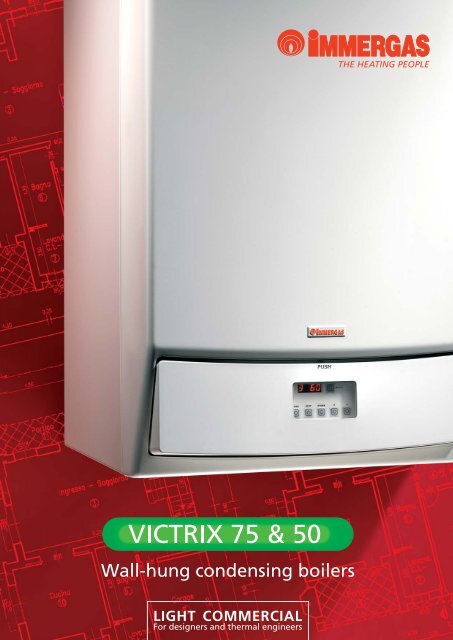
VICTRIX 75<br />
VICTRIX 75 is an open chamber fan assisted wall-hung condensing boiler for heating only,<br />
equipped with circulator and safety valve. The boiler is approved for installation in both<br />
indoor heating plants and outside buildings, without requiring additional protection. It can<br />
be installed as single appliance or in cascade.<br />
The generator is equipped with electronic board, allowing to adjust the functioning<br />
parameters of the appliance to the specific exigenc<strong>ie</strong>s of every single system.<br />
• Nominal heat output of 72 kW;<br />
• Minimum heat output of 18 kW;<br />
• Compact dimensions;<br />
• Stainless steel condensing module;<br />
• 4 bar safety valve with discharge funnel;<br />
• Double NTC probe for optimum temperature control;<br />
• IPX5D protection index;<br />
• Frost protection up to -5°C;<br />
• Control board with visual display;<br />
• Autodiagnosis system;<br />
• Possibility to connect a separate storage tank unit.<br />
Model Height Width Depth<br />
VICTRIX 75 9<strong>50</strong> mm 600 mm 525 mm<br />
Model<br />
Code<br />
N.G.<br />
L.P.G.<br />
Heat<br />
output<br />
kW<br />
Effic<strong>ie</strong>ncy<br />
rating<br />
(D.P.R. 660/96)<br />
Condensing/<br />
premixed<br />
burner<br />
Reduced<br />
pollutant emissions<br />
(NOx-CO)<br />
Protection<br />
index<br />
Frost<br />
protection<br />
VICTRIX 75 3.018511 72,6 4 stars IPX5D -5°C<br />
3.018511GPL<br />
MAIN OPTIONS<br />
Type Code<br />
External sensor 3.015266<br />
Three-way valve kit 3.015223<br />
Hydraulic manifold kit 3.015224<br />
MAIN FLUE KITS<br />
Type Code<br />
Terminal horizontal outlet kit Ø 80 3.015255<br />
Terminal vertical outlet kit Ø 80 3.015256<br />
Horizontal concentric kit Ø 80/125 3.015242<br />
For good performance and safe operation use Immergas “Green Ser<strong>ie</strong>s” pipes and terminal flue outlet only.<br />
NEW
VICTRIX <strong>50</strong><br />
VICTRIX <strong>50</strong> is an open chamber fan assisted wall-hung condensing boiler for heating only,<br />
equipped with circulator and safety valve. The boiler is approved for installation in both<br />
indoor heating plants and outside buildings, without requiring additional protection. It can<br />
be installed as single appliance or in cascade.<br />
The generator is equipped with electronic board, allowing to adjust the functioning<br />
parameters of the appliance to the specific exigenc<strong>ie</strong>s of every single system.<br />
• Nominal heat output of <strong>50</strong> kW;<br />
• Minimum heat output of 10 kW;<br />
• Compact dimensions;<br />
• Stainless steel condensing module;<br />
• 4 bar safety valve with discharge funnel;<br />
• Double NTC probe for optimum temperature control;<br />
• IPX5D protection index;<br />
• Frost protection up to -5°C;<br />
• Control board with visual display;<br />
• Autodiagnosis system;<br />
• Possibility to connect a separate storage tank unit.<br />
Model Height Width Depth<br />
VICTRIX <strong>50</strong> 9<strong>50</strong> mm 600 mm 525 mm<br />
Model<br />
Code<br />
N.G.<br />
L.P.G.<br />
Heat<br />
output<br />
kW<br />
Effic<strong>ie</strong>ncy<br />
rating<br />
(D.P.R. 660/96)<br />
Condensing/<br />
premixed<br />
burner<br />
Reduced<br />
pollutant emissions<br />
(NOx-CO)<br />
Protection<br />
index<br />
Frost<br />
protection<br />
VICTRIX <strong>50</strong> 3.016359 <strong>50</strong>,0 4 stars IPX5D -5°C<br />
3.016359GPL<br />
MAIN OPTIONS<br />
Type Code<br />
External sensor 3.015266<br />
Three-way valve kit 3.015223<br />
Hydraulic manifold kit 3.015224<br />
MAIN FLUE KITS<br />
Type Code<br />
Terminal horizontal outlet kit Ø 80 3.015255<br />
Terminal vertical outlet kit Ø 80 3.015256<br />
Horizontal concentric kit Ø 80/125 3.015242<br />
For good performance and safe operation use Immergas “Green Ser<strong>ie</strong>s” pipes and terminal flue outlet only.<br />
9
10<br />
Main dimensions and connections<br />
Horizontal<br />
concentric kit Ø 80/125<br />
HYDRAULIC CONNECTIONS<br />
HEATING<br />
R<br />
M<br />
Circulator head and flow rate graph<br />
VICTRIX <strong>50</strong><br />
Head (kPa)<br />
90<br />
80<br />
70<br />
60<br />
<strong>50</strong><br />
40<br />
30<br />
20<br />
10<br />
Flow Rate/Head graph<br />
0<br />
0<br />
0 200 400 600 800 1000 1200 1400 1600 1800 2000 2200 2400 2600<br />
Flow rate (l/h)<br />
9.18<br />
8.16<br />
7.14<br />
6.12<br />
5.10<br />
4.08<br />
3.06<br />
2.04<br />
1.02<br />
Available head in the system:<br />
----- Available head at top speed with single boiler<br />
-----Available head at second speed with single boiler<br />
-----Available head at top speed with non return valve for boilers in cascade<br />
----- Available head at second speed with non return valve for boilers in cascade<br />
Head (m H 2O)<br />
GAS<br />
G<br />
3/4”<br />
Key:<br />
V - Electrical connection<br />
M - System delivery<br />
SC - Condensate drain<br />
G - Gas supply<br />
R - System return<br />
VICTRIX 75<br />
Head (kPa)<br />
90<br />
80<br />
70<br />
60<br />
<strong>50</strong><br />
40<br />
30<br />
20<br />
10<br />
11/2”<br />
Flow Rate/Head graph<br />
11/2”<br />
Flow rate (l/h)<br />
Horizontal outlet<br />
kit Ø 80<br />
CONDENSATE DRAIN<br />
SC<br />
25 mm<br />
0<br />
0<br />
0 200 400 600 800 1000 1200 1400 1600 1800 2000 2200 2400 2600<br />
9.18<br />
8.16<br />
7.14<br />
6.12<br />
5.10<br />
4.08<br />
3.06<br />
2.04<br />
1.02<br />
Head (m H 2O)
Main dimensions and connections<br />
with a single boiler<br />
3 4<br />
11
12<br />
Hydraulic and electric diagrams<br />
Single generator for room heating and domestic hot water production with the storage tank connected to solar panels<br />
Hydraulic scheme<br />
Gas supply<br />
Electrical scheme<br />
Condensate<br />
Drain<br />
System filling<br />
Key:<br />
1 - VICTRIX <strong>50</strong>/75 generator<br />
2 - Room thermostat<br />
3 - External probe<br />
4 - Thermometer trap<br />
5 - Fuel on-off valve bulb<br />
6 - ISPESL approved pressure gauge cock<br />
7 - Fuel on-off valve<br />
8 - ISPESL approved thermometer<br />
9 - ISPESL approved manually reset<br />
thermostat<br />
10 - ISPESL approved manually reset<br />
pressure switch<br />
Black<br />
Orange<br />
Red<br />
11 - System circulator<br />
12 - Expansion vessel connection<br />
13 - Expansion vessel<br />
14 - Three way valve<br />
15 - Manifold/mixer<br />
16 - Sludge collecting system filter<br />
17 - External storage tank unit<br />
18 - Storage tank unit probe<br />
19 - Solar panel control unit<br />
20 - Solar panel circulator<br />
21 - Solar panel<br />
22 - Solar panel probe<br />
Key:<br />
1 - VICTRIX <strong>50</strong>/75<br />
2 - External probe<br />
3 - Storage tank unit probe<br />
4 - Room thermostat<br />
5 - Three way valve
Single generator with high/low temperature zones system with separate storage tank for the domestic hot water production<br />
Hydraulic scheme<br />
Key:<br />
1 - VICTRIX 75/<strong>50</strong> generator<br />
2 - External probe<br />
3 - Thermometer trap<br />
4 - Fuel on-off valve bulb<br />
5 - ISPESL approved pressure gauge cock<br />
6 - Fuel on-off valve<br />
Gas supply<br />
Electrical scheme<br />
Condensate<br />
Drain<br />
Key:<br />
1 - Zone 3 direct circuit pump (CD)<br />
2 - Storage tank unit supply pump<br />
3 - Storage tank unit probe<br />
4 - Zone 1 mixer valve (CMI-1)<br />
5 - Zone 1 heating circuit pump (CMI-1)<br />
6 - Zone 1 safety thermostat (CMI-1)<br />
7 - Zone 1 temperature probe (CMI-1)<br />
8 - Zone 2 mixer valve (CMI-2)<br />
9 - Zone 2 heating circuit pump (CMI-2)<br />
10 - Zone 2 safety thermostat (CMI-2)<br />
11 - Zone 2 temperature probe (CMI-2)<br />
12 - Common delivery probe<br />
13 - Zone manager<br />
14 - Modulating room thermostat<br />
15 - External main switch<br />
16 - External probe<br />
17 - Cascade and zones regulator<br />
18 - VICTRIX 75/<strong>50</strong> generator<br />
System filling<br />
7 - ISPESL approved thermometer<br />
8 - ISPESL approved manually reset thermostat<br />
9 - ISPESL approved manually reset pressure switch<br />
10 - Expansion vessel connection<br />
11 - Expansion vessel<br />
12 - Manifold/mixer<br />
13 - Sludge collecting system filter<br />
14 - Common delivery probe<br />
15 - Zone manager<br />
16 - Zone 1 safety thermostat (CMI-1)<br />
17 - Zone 1 heating circuit pump (CMI-1)<br />
18 - Zone 1 temperature probe (CMI-1)<br />
ZONE 1<br />
(CMI1)<br />
ZONE 2<br />
(CMI2)<br />
ZONE 3<br />
(CD)<br />
ZONE 3 STORAGE TANK UNIT ZONE 1 ZONE 2<br />
230 Vac <strong>50</strong>Hz<br />
Common<br />
Open<br />
Close<br />
Common<br />
Open<br />
Close<br />
19 - Zone 1 mixer valve (CMI-1)<br />
20 - Zone 2 safety thermostat (CMI-2)<br />
21 - Zone 2 heating circuit pump (CMI-2)<br />
22 - Zone 2 temperature probe (CMI-2)<br />
23 - Zone 2 mixer valve (CMI-2)<br />
24 - Modulating room thermostat<br />
25 - Non return valve<br />
26 - Zone 3 direct circuit pump (CD)<br />
27 - Cascade and zones regulator<br />
28 - Storage tank unit supply pump<br />
29 - Storage tank unit<br />
30 - Storage tank unit probe<br />
13
14<br />
Main dimensions and connections<br />
with boilers in cascade
Double battery of generators with high/low temperature zones system and separate storage tank for the domestic hot water production<br />
Hydraulic scheme Key:<br />
1 - VICTRIX 75/<strong>50</strong> generator<br />
2 - System shut off knob<br />
3 - Non return valve<br />
4 - Fuel on-off valve<br />
5 - External probe<br />
Condensate<br />
Drain<br />
Gas supply<br />
Electrical scheme<br />
ZONE 3 STORAGE TANK UNIT ZONE 1 ZONE 2<br />
230 Vac<br />
<strong>50</strong>Hz<br />
Common<br />
Open<br />
Close<br />
System filling<br />
Common<br />
Open<br />
Close<br />
6 - Thermometer trap<br />
7 - ISPESL approved thermometer<br />
8 - ISPESL approved manually reset pressure<br />
switch<br />
9 - ISPESL approved manually reset thermostat<br />
10 - ISPESL approved pressure gauge cock<br />
11 - Fuel on-off valve bulb<br />
12 - Expansion vessel connection<br />
13 - Expansion vessel<br />
14 - Common delivery probe<br />
15 - Sludge collecting system filter<br />
16 - Manifold/mixer<br />
17 - Zone manager<br />
18 - Modulating room thermostat<br />
19 - Zone 1 safety thermostat (CMI-1)<br />
20 - Zone 1 heating circuit pump (CMI-1)<br />
21 - Zone 1 temperature probe (CMI-1)<br />
22 - Zone 1 mixer valve (CMI-1)<br />
23 - Zone 2 safety thermostat (CMI-2)<br />
24 - Zone 2 heating circuit pump (CMI-2)<br />
25 - Zone 2 temperature probe (CMI-2)<br />
26 - Zone 2 mixer valve (CMI-2)<br />
27 - Zone 3 direct circuit pump (CD)<br />
28 - Cascade and zones regulator<br />
29 - Storage tank unit supply pump<br />
30 - Storage tank unit<br />
31 - Storage tank unit probe<br />
Key:<br />
1 - Zone 3 direct circuit pump (CD)<br />
2 - Storage tank unit supply pump<br />
3 - Storage tank unit probe<br />
4 - Zone 1 mixer valve (CMI-1)<br />
5 - Zone 1 heating circuit pump (CMI-1)<br />
6 - Zone 1 safety thermostat (CMI-1)<br />
7 - Zone 1 temperature probe (CMI-1)<br />
8 - Zone 2 mixer valve (CMI-2)<br />
9 - Zone 2 heating circuit pump (CMI-2)<br />
10 - Zone 2 safety thermostat (CMI-2)<br />
11 - Zone 2 temperature probe (CMI-2)<br />
12 - Common delivery probe<br />
13 - Zone manager<br />
14 - Modulating room thermostat<br />
15 - External main switch<br />
16 - Cascade and zones regulator<br />
17 - External probe<br />
18 - VICTRIX 75/<strong>50</strong> generator<br />
Address 0 Address 1 Address 2 Address 3 Address 4 Address 5<br />
ZONE 1<br />
(CMI1)<br />
ZONE 2<br />
(CMI2)<br />
ZONE 3<br />
(CD)<br />
15
16<br />
Battery of generators with 6 high/low temperature zones systems and 2 separate storage tanks for the domestic hot water production<br />
Hydraulic scheme<br />
Key:<br />
1 - VICTRIX 75/<strong>50</strong> generator<br />
2 - System shut off knob<br />
3 - Non return valve<br />
4 - Fuel on-off valve<br />
5 - External probe<br />
6 - Thermometer trap<br />
7 - ISPESL approved thermometer<br />
8 - ISPESL approved manually reset pressure switch<br />
9 - ISPESL approved manually reset thermostat<br />
10 - ISPESL approved pressure gauge cock<br />
11 - Fuel on-off valve bulb<br />
12 - Expansion vessel connection<br />
13 - Expansion vessel<br />
14 - Common delivery probe<br />
15 - Sludge collecting system filter<br />
16 - Manifold/mixer<br />
Electrical scheme<br />
ZONE 3 STORAGE TANK<br />
UNIT<br />
230Vac<br />
<strong>50</strong>Hz<br />
Condensate<br />
drain<br />
Gas supply<br />
Common<br />
Open<br />
Close<br />
ZONE 1<br />
Common<br />
Open<br />
Close<br />
17 - Cascade and zones regulator<br />
18 - Zone manager<br />
19 - Modulating room thermostat<br />
20 - Zone 1 safety thermostat (CMI-1)<br />
21 - Zone 1 heating circuit pump (CMI-1)<br />
22 - Zone 1 temperature probe (CMI-1)<br />
23 - Zone 1 mixer valve (CMI-1)<br />
24 - Zone 2 safety thermostat (CMI-2)<br />
25 - Zone 2 heating circuit pump (CMI-2)<br />
26 - Zone 2 temperature probe (CMI-2)<br />
27 - Zone 2 mixer valve (CMI-2)<br />
28 - Zone 3 direct circuit pump (CD)<br />
29 - Storage tank unit supply pump<br />
30 - Storage tank unit<br />
31 - Storage tank unit probe<br />
32 - balancing valve<br />
ZONE 2 ZONE 3-1 STORAGE TANK<br />
UNIT<br />
ZONE 1-1 ZONE 2-1<br />
Address 0 Address 1 Address 2<br />
System filling<br />
Common<br />
Open<br />
Close<br />
ZONE 1<br />
(CMI1)<br />
ZONE 1<br />
(CMI1)<br />
Common<br />
Open<br />
Close<br />
Key:<br />
1 - Zone 3 direct circuit pump (CD)<br />
2 - Storage tank unit supply pump<br />
3 - Storage tank unit probe<br />
4 - Zone 1 mixer valve (CMI-1)<br />
5 - Zone 1 heating circuit pump (CMI-1)<br />
6 - Zone 1 safety thermostat (CMI-1)<br />
7 - Zone 1 temperature probe (CMI-1)<br />
8 - Zone 2 mixer valve (CMI-2)<br />
9 - Zone 2 heating circuit pump (CMI-2)<br />
ZONE 2<br />
(CMI2)<br />
ZONE 2<br />
(CMI2)<br />
ZONE 3<br />
(CD)<br />
ZONE 3<br />
(CD)<br />
10 - Zone 2 safety thermostat (CMI-2)<br />
11 - Zone 2 temperature probe (CMI-2)<br />
12 - Common delivery probe<br />
13 - Zone manager<br />
14 - Modulating room thermostat<br />
15 - External main switch<br />
16 - Cascade and zones regulator<br />
17 - External probe<br />
18 - VICTRIX 75/<strong>50</strong> generator
Technical information<br />
Maximum nominal heat input (heating)<br />
Minimum nominal heat input (heating)<br />
Maximum nominal heat output (heating)<br />
Minimum nominal heat output (heating)<br />
Effic<strong>ie</strong>ncy at nominal heat output (80/60 °C)<br />
Effic<strong>ie</strong>ncy at 30% of load (80/60 °C)<br />
Effic<strong>ie</strong>ncy at nominal heat output (<strong>50</strong>/30 °C)<br />
Effic<strong>ie</strong>ncy at 30% of load (<strong>50</strong>/30 °C)<br />
Effic<strong>ie</strong>ncy at nominal heat output (40/30 °C)<br />
Effic<strong>ie</strong>ncy at 30% of load (40/30 °C)<br />
Stack losses with burner on<br />
Stack losses with burner off<br />
Casing losses with burner on<br />
Casing losses with burner off<br />
Gas consumption at nominal heat output (heating)*<br />
Fumes temperature at max. nominal heat input*<br />
Fumes temperature at min. nominal heat input*<br />
Fumes flow rate at max. nominal heat input*<br />
Fumes flow rate at min. nominal heat input*<br />
CO2 at maximum heat input*<br />
CO2 at minimum heat input*<br />
CO at maximum heat input with 0% of O2*<br />
CO at minimum heat input with 0% of O2*<br />
NOx at maximum heat input with 0% of O2*<br />
NOx at minimum heat input with 0% of O2*<br />
Weighted CO*<br />
Weighted NOx *<br />
NOx class<br />
Central heating temperature range<br />
Maximum heating temperature<br />
Maximum operating pressure<br />
Available head with 1000 l/h flow rate<br />
Dimensions<br />
Height<br />
Width<br />
Depth<br />
Electrical supply<br />
Nominal power draw<br />
Installed electric power<br />
Fan power consumption<br />
Circulator power consumption<br />
Protection index<br />
Boiler water content<br />
Full appliance weight<br />
* With natural gas<br />
Unit of measurement<br />
kW<br />
kW<br />
kW<br />
kW<br />
%<br />
%<br />
%<br />
%<br />
%<br />
%<br />
%<br />
%<br />
%<br />
%<br />
m3/h °C<br />
°C<br />
kg/h<br />
kg/h<br />
%<br />
%<br />
ppm<br />
ppm<br />
ppm<br />
ppm<br />
mg/kWh<br />
mg/kWh<br />
-<br />
°C<br />
°C<br />
bar<br />
kPa<br />
mm<br />
mm<br />
mm<br />
V / Hz<br />
A<br />
W<br />
W<br />
W<br />
IP<br />
litres<br />
Kg<br />
VICTRIX <strong>50</strong><br />
<strong>50</strong>,8<br />
10,4<br />
<strong>50</strong>,0<br />
10,0<br />
98,5<br />
96,0<br />
106,0<br />
106,5<br />
107,0<br />
107,0<br />
1,3<br />
0,02<br />
0,2<br />
0,47<br />
5,37<br />
38<br />
30<br />
81<br />
17<br />
9,3<br />
9,0<br />
120<br />
6<br />
39<br />
16<br />
38<br />
55<br />
5<br />
20 - 85<br />
90<br />
4,4<br />
52,9<br />
9<strong>50</strong><br />
600<br />
525<br />
230 / <strong>50</strong><br />
0,85<br />
180<br />
59<br />
115<br />
X5D<br />
3,7<br />
69<br />
VICTRIX 75<br />
74,6<br />
18,5<br />
72,6<br />
18,1<br />
97,3<br />
101,0<br />
104,5<br />
107,6<br />
107,0<br />
107,6<br />
2,3<br />
0,01<br />
0,4<br />
0,32<br />
7,90<br />
61<br />
48<br />
121<br />
31<br />
9,2<br />
8,9<br />
170<br />
7<br />
108<br />
54<br />
43<br />
<strong>50</strong><br />
5<br />
20 - 85<br />
90<br />
4,4<br />
65,5<br />
9<strong>50</strong><br />
600<br />
525<br />
230 / <strong>50</strong><br />
1,26<br />
270<br />
72<br />
168<br />
X5D<br />
4,0<br />
72<br />
17
18<br />
Flue systems<br />
Single installation<br />
VICTRIX <strong>50</strong> and VICTRIX 75 boilers are standard provided in B23 configuration (open chamber, fan assisted) but they can work also as sealed chamber fan assisted<br />
(C type) using the special kits suppl<strong>ie</strong>d by Immergas.<br />
To correctly install the boiler, it is necessary to use the original Immergas “Green Ser<strong>ie</strong>s” flue systems; these components and accessor<strong>ie</strong>s are specially designed for<br />
VICTRIX <strong>50</strong> and VICTRIX 75 to guarantee higher resistance to corrosion and fast and easy installation, thanks also to the push-fit assembly and special gasket<br />
seals.<br />
FLUE OUTLET KITS FOR OPEN CHAMBER FAN ASSISTED INSTALLATION (B23 TYPE)<br />
Description Code<br />
Horizontal kit Ø 80 (to discharge in the chimney) 3.015254<br />
Terminal horizontal outlet kit Ø 80 (to discharge horizontally) 3.015255<br />
Terminal vertical outlet kit Ø 80 3.015256<br />
4 extension pipes Ø 80 kit 0,5 m long 3.014642<br />
4 extension pipes Ø 80 kit 1 m long 3.012088<br />
1 extension pipe Ø 80 2 m long 3.016837<br />
4 x 90° bends Ø 80 kit 3.012091<br />
45° bend Ø 80 kit 3.012092
FLUE OUTLET KITS FOR SEALED CHAMBER FAN ASSISTED INSTALLATION (C TYPE)<br />
Description Code<br />
Horizontal concentric kit Ø 80/125 3.015242<br />
Vertical concentric kit Ø 80/125 3.015243<br />
Flashing Kit Ø 80/125 for flat roof 3.015249<br />
Extension pipe kit Ø 80/125 2 m long 3.015246<br />
87° bend kit Ø 80/125 3.015247<br />
2 x 45° bend kit Ø 80/125 3.015248<br />
19
20<br />
Cascade installation<br />
In case of cascade systems in B23 configuration (open chamber, fan assisted), it is necessary to use a special flue manifold with a non-return device (flue locks)<br />
suppl<strong>ie</strong>d by Immergas, so that the combustion products of one working boiler do not interfere with the combustion circuit of the not working boilers. The flue manifold<br />
has an external diameter of 125 mm.<br />
Description Code<br />
Exhaust manifold kit with flue locks Ø 125 for 2 boilers 3.015240<br />
in cascade (including a condense draining siphon)<br />
Exhaust manifold kit with flue lock for the additional boiler 3.015241<br />
Extension pipe Ø 125 kit 0,5 m long for flue manifold 3.016370<br />
Extension pipe Ø 125 kit 1 m long for flue manifold 3.016371<br />
Extension pipe Ø 125 kit 2 m long for flue manifold 3.0152<strong>50</strong><br />
90° bend kit Ø 125 mm for flue manifold 3.016179<br />
2 x 45° bend kit Ø 125 mm for flue manifold 3.016180<br />
Adapter Ø 125 - 160 for flue manifold 3.016215
Main climatic regulation options<br />
Description Code<br />
Cascade and zones regulator 3.015244<br />
Wall box for cascade and zones regulator 3.015265<br />
Zone manager 3.015264<br />
Modulating room thermostat 3.015245<br />
Flow probe 3.015267<br />
Storage tank sensor 3.015268<br />
(for managing the storage tank as a zone)<br />
Electrical connection kit for cascade 3.015269<br />
and zones regulator<br />
(to be installed to an external electric panel)<br />
External sensor 3.015266<br />
21
22<br />
Main hydraulic options<br />
Description Code<br />
Safety kit for single boiler 3.015222<br />
(it includes thermometer, thermometer holder, lock, thermostat<br />
with manual reset, connection tap for pressure gauge,<br />
manual reset pressostat, gas intercepting valve trap,<br />
expansion vessel connection)<br />
Three-way valve kit connection to the separate storage tank 3.015223<br />
(it includes the storage tank probe)<br />
Hydraulic manifold for single boiler 3.015224<br />
(it includes a mud-filter on the return pipe)<br />
Hydraulic manifold for 2 boilers in cascade 3.015225<br />
(including the intercepting valve and the non-return<br />
for each appliance)<br />
Hydraulic manifold for additional boiler in cascade 3.015226<br />
(including the intercepting valve and the non-return valve)<br />
Safety kit for boilers in cascade 3.015227<br />
(it includes thermometer, thermometer holder, lock thermostat<br />
with manual reset, connection tap for pressure gauge,<br />
manual reset pressostat, gas intercepting valve trop,<br />
expansion vessel connection)
Notes<br />
23