Ergonomics - Atlas Copco
Ergonomics - Atlas Copco
Ergonomics - Atlas Copco

Create successful ePaper yourself
Turn your PDF publications into a flip-book with our unique Google optimized e-Paper software.
Power Tool<br />
<strong>Ergonomics</strong><br />
E V A L U A T I O N O F P O W E R T O O L S
Power Tool<br />
ergonomics<br />
E V A L U A T I O N OF P O W E R T O O L S
Acknowledgements<br />
While doing research for this book, I found that<br />
there were gaps in the scientific data available.<br />
My colleagues’ comments, based on years of<br />
practical experience, have been very valuable<br />
in helping to fill these gaps. Among the persons<br />
consulted with scientific backgrounds I would<br />
like to mention Shihan Bao. Shihan completed<br />
his Ph.D. thesis, “Shoulder-neck exposure from<br />
assembly work, and the significance of rationalization”,<br />
around the time I began writing this<br />
book. He participated in the research related<br />
to his specific field and made a very valuable<br />
contribution. Warm thanks to Shihan and my<br />
colleagues for their encouragement and support.<br />
Bo Lindqvist<br />
Authors: Bo Lindqvist, Lars Skogsberg<br />
Editorial consultant: David Bennett<br />
Cover design: Mikael Skoog<br />
Illustrations: Martin Gradén<br />
Photo contributions: Jonas Brane, BLR-fotograferna,<br />
Dennis Josefsson, Rolf Kukacka, Lars Lindgren,<br />
Björn Lundbladh, Lars Nybom, Jan Strömberg,<br />
Dag Sundberg, Kenneth Westerlund<br />
Printed by Strokirk-Landströms 2007.<br />
A know-how publication from <strong>Atlas</strong> <strong>Copco</strong><br />
ISBN: 978-91-631-9900-4<br />
Price: SEK 150, EUR 16, US$ 21.<br />
<strong>Atlas</strong> <strong>Copco</strong> Printed Matter<br />
No. 9833 1162 01<br />
Preface to the second edition<br />
The first edition of this book was the last major<br />
contribution that my late colleague and good<br />
friend Mr. Bo Lindqvist made to the science of<br />
power tool ergonomics. It was with great reluctance<br />
that I undertook the task of upgrading this<br />
book to a second edition. The unique evaluation<br />
method that he presented in the first edition has<br />
been very well accepted and his method is used by<br />
many large companies in Europe and the US. I<br />
feared that I would, to some extent, take the credit<br />
for this major contribution away from him.<br />
However, as time passes, things change, I<br />
now believe that the best way to show my respect<br />
for Bo is to carry on his work and further develop<br />
his method based on new knowledge, new standardization<br />
and the experience gained from the<br />
use of his method.<br />
In this second edition I have only made the<br />
revisions necessary to bring the book up to date.<br />
Some of the graphs for conversion from evaluated<br />
parameters to points are adjusted. I have<br />
added a section on wrist torque based on recent<br />
research conducted by <strong>Atlas</strong> <strong>Copco</strong>. The sections<br />
on noise and vibration have been revised slightly<br />
to reflect the new situation in Europe following<br />
the publication of the Physical Agents Directives<br />
for noise and vibration. The examples at the end<br />
of the book have been updated and are based on<br />
the most modern tools on the market. In addition,<br />
some photos have been replaced by images that<br />
reflect the current situation more accurately.<br />
Lars Skogsberg<br />
Manager, Product <strong>Ergonomics</strong>
1. The workplace<br />
Good ergonomics is good economics 8<br />
Work organization 12<br />
Sitting assembly workstation 15<br />
Standing workstation 21<br />
Standing assembly line workstation 27<br />
2. Main types of power tools<br />
Grinders 32<br />
Drills 37<br />
Percussive tools 41<br />
Screwdrivers 45<br />
Impact and impulse nutrunners 49<br />
Angle nutrunners 53<br />
High torque nutrunners designed for use with reaction bars 58<br />
3. Evaluation of power tools<br />
Introduction 62<br />
Handle design 64<br />
External load 73<br />
Weight 88<br />
Temperature 92<br />
Shock reaction 97<br />
Vibration 103<br />
Noise 116<br />
Dust and oil 125<br />
4. Evaluation examples<br />
Grinder GTG 40 F085 134<br />
Drill LBB 26 EPX-060 138<br />
Chipping hammer RRF 31 142<br />
Riveting hammer RRH 06 146<br />
Screwdriver LUM 22 PR4 150<br />
Impulse nutrunner, ErgoPulse EP9 PTX80-HR13 154<br />
Electric nutrunner ETP ST32-05-10 158<br />
Angle nutrunner LTV 29 R30-10 162<br />
Electric angle nutrunner, Tensor ST61-50-10 166<br />
High torque nutrunner LTP51 170
How to get the best<br />
out of this book<br />
If, like most of us, you’re in a hurry, go<br />
directly to Chapter 4 where you will find<br />
examples and a diagram showing a com-<br />
parison of ergonomic factors for the type<br />
of tool you are interested in. Here you will<br />
find an evaluation of the ergonomic factors<br />
mentioned in the book.<br />
Each diagram gives an evaluation of one<br />
particular tool and an idea of what to expect<br />
from other tools in the same family.<br />
Don’t be discouraged by the amount of<br />
information the book contains – it is not<br />
intended to be read from cover to cover in<br />
one heroic attempt.<br />
Good ergonomics is good economics<br />
The first chapter deals with the planning<br />
and operation of a production unit and typi-<br />
cal work environments where power tools<br />
are used.<br />
Main tool types<br />
The next chapter describes several main<br />
types of power tool and includes brief com-<br />
ments on ergonomic factors influencing<br />
the operator.<br />
Guide for evaluation<br />
The idea is to develop a method for compar-<br />
ing the impact of some major ergonomic<br />
factors on the operator during the work<br />
process. The method provides a systematic<br />
approach to assessing the ergonomic aspects<br />
of a tool in order to identify problems and<br />
areas requiring improvement.<br />
The state of the art<br />
The final chapter gives examples of specific<br />
tools. We believe them to be the best on the<br />
market. As such, they represent the state<br />
of the art for hand-held tool design. These<br />
tools are evaluated using the guide.
Preface<br />
The author, Bo Lindqvist.<br />
ergonomics at <strong>Atlas</strong> <strong>Copco</strong> Tools<br />
As a company developing hand-held power<br />
tools, <strong>Atlas</strong> <strong>Copco</strong> Tools has for decades<br />
been aware of the importance of ergonomics<br />
in design.<br />
<strong>Atlas</strong> <strong>Copco</strong> first began applying ergonom-<br />
ics in the 1950’s during the development of<br />
a drill. Medical experts were consulted fre-<br />
quently at the design stage and asked to give<br />
their opinions on different grips. The result<br />
was a machine that quickly became popular<br />
on the market.<br />
In the late sixties Bo Lindqvist was em-<br />
ployed to start a tool ergonomics department.<br />
An acoustics laboratory was built at the<br />
beginning of the seventies, and research<br />
into noise and vibration began. In the mid-<br />
dle of the same decade <strong>Atlas</strong> <strong>Copco</strong> intro-<br />
duced a vibration controlled chipping ham-<br />
mer. This tool was the first of a long series<br />
of noise and vibration controlled tools and<br />
we are still improving our skills to design<br />
even better tools.<br />
During the early seventies we also de-<br />
signed and installed a spot suction system<br />
in a vehicle repair shop. This project showed<br />
that it was technically possible to equip a<br />
hand-held tool with a dust collector and<br />
suck away the dust created by the process,<br />
without obstructing the operator too much<br />
in the performance of his task.<br />
Other ergonomic factors have been stud-<br />
ied, such as shock reaction from angle nut-<br />
runners, and machines have been designed<br />
with very fast clutches to minimize the<br />
impulse that strives to move the machine in<br />
the operator’s hands.
Work with international standards<br />
In the late seventies Bo Lindqvist became<br />
the chairman of Pneurop 17 Vibration<br />
and, subsequently, convenor for ISO/TC<br />
118/SC 3/WG 3, an international standards<br />
group charged with the task of developing<br />
standards for vibration measurement. The<br />
group’s efforts resulted in a series of stand-<br />
ards designated ISO 8662. Similar work has<br />
been done to develop noise test codes.<br />
Previous edition<br />
The first edition of Power Tool <strong>Ergonomics</strong><br />
was published in 1997 and distributed in<br />
40,000 copies.<br />
New possibilities<br />
Over the years we have experienced re-<br />
markable developments in measuring<br />
instruments and computers. Today it is<br />
easier to analyse a phenomenon. We can use<br />
multi-channel vibration measurements to<br />
see a motion, or we can produce the same<br />
effect in a simulation at a very early stage<br />
of the design.<br />
The purpose of this book<br />
Ten years ago we talked about ergonomic<br />
tools. Nowadays, we talk about tools with<br />
good ergonomics. The reason is that in<br />
every design we try to find the best possi-<br />
ble solution, weighing up a combination of<br />
ergonomic, technical and economic factors<br />
against each other. This is a complicated<br />
task and this book deals only with ergonomic<br />
factors, although for the operator other fac-<br />
tors may be equally important.<br />
In order to give the subject of power tool<br />
ergonomics a framework into which we can<br />
place our views and experience, we have<br />
selected a number of factors and developed<br />
an evaluation method to compare them.<br />
Our task is not made any easier by the<br />
lack of research data for some ergonomic<br />
factors, although this is a familiar situa-<br />
tion for us in the manufacturing industry.<br />
We cannot afford to wait for solid data. We<br />
often have to make an educated guess and<br />
trust our experience. Otherwise we would<br />
soon be out of the market.<br />
When you select a hand-held power tool,<br />
you not only influence the process, but also<br />
the operator’s work situation and the entire<br />
working environment. The aim of this book<br />
is to illustrate this interaction.
1THE WORKPLACE
Good ergonomics<br />
is good economics<br />
When planning a production unit, it pays<br />
dividends in the long term to consult<br />
people qualified in ergonomics. They help<br />
to ensure that both the workplace and the<br />
task are compatible with the majority of<br />
operators who will work there. Thus, future<br />
costs arising from work-related health<br />
disorders among operators will be reduced,<br />
along with costs arising from poor product<br />
quality. Moreover, the need to redesign the<br />
production system later may be avoided.<br />
When planning a production unit, involving ergonomists<br />
from the start avoids problems later.<br />
Costs related to bad ergonomics<br />
The driving force for all ergonomists is to<br />
reduce the number of people suffering from<br />
work-related disorders. However, the acces-<br />
sibility of funding for the required improve-<br />
ments in the workplace depends heavily on<br />
economic factors such as payback time and<br />
return on investments.<br />
Today, the direct and indirect costs of<br />
work-related disorders are an increasingly<br />
frequent topic for discussion.<br />
Obtaining figures for these costs from<br />
companies is difficult. This is partly because<br />
many companies have not made such calcu-<br />
lations, and partly because those who have<br />
are reluctant to release the information to<br />
the public.<br />
Some general figures can be given.<br />
Large companies spend 10-100 million USD<br />
on work-related disorders every year. The<br />
cost of taking care of one case of carpal tun-<br />
nel syndrome is 10–30 000 USD.
This is only the direct cost. The indirect<br />
costs generated by work-related disorders<br />
are primarily in connection with productiv-<br />
ity losses and quality problems. The rela-<br />
tionship between direct and indirect costs is<br />
not really known, but indications are that<br />
the indirect cost may be in the order<br />
of three times the direct cost.<br />
Today we see a growing demand for<br />
more scientific research in this field. When<br />
the true extent of costs related to bad ergo-<br />
nomics is made public, the possibilities of<br />
obtaining funding for workplace improve-<br />
ments will be much improved.<br />
ergonomics<br />
<strong>Ergonomics</strong> is a relatively new science<br />
combining knowledge from three disciplines<br />
– human science, work-related sciences and<br />
production science. Few ergonomists cover<br />
the entire field and it is usually personal<br />
interest that determines the individual’s<br />
profile of expertise.<br />
Teamwork contributes to the total<br />
knowledge available. In a planning situation<br />
all team members can become ergonomists in<br />
their search for human and practical solutions.<br />
The role of the trained ergonomist is<br />
to support the team and try to identify in advance<br />
work situations where excessive loads<br />
are likely to be placed on the operator.<br />
Operator involvement<br />
An operator with a high level of job satisfaction<br />
can be motivated to work more<br />
efficiently and to become more actively<br />
involved in the production system. Thus,<br />
increased productivity and improved product<br />
quality can be expected. Compatibility<br />
between machine, work organization and<br />
operator is therefore crucial to work performance<br />
and product quality.<br />
If the physical and psychological demands<br />
of a production system exceed an operator’s<br />
capacity for a prolonged period, the<br />
operator may suffer work injuries. Improving<br />
the interaction between the operators<br />
and their working environment is a major<br />
task on the agenda of most industries.<br />
To achieve the ultimate goal of increasing<br />
overall productivity, an optimal interaction<br />
between the operators and their working<br />
environment should be established, and<br />
poor interaction eliminated.<br />
This task calls for simultaneous study<br />
of the work organization, machines, workstations,<br />
production procedures, the physical<br />
and psychological capabilities of the<br />
employees, and the combined interaction<br />
of all these elements.
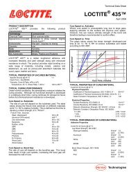
10<br />
SOCIOLOGY INDUSTRIAL<br />
SOCIOLOGY<br />
SOCIAL<br />
PSYCHOLOGY<br />
PSYCHOLOGY<br />
PSYCHOLOGY<br />
MEDICINE<br />
Fig. 1.1 <strong>Ergonomics</strong> is<br />
a multi-disciplinary<br />
science.<br />
Adapting the workstation<br />
to the operator<br />
WORK<br />
EXPERIENCE; SOCIAL<br />
PSYCHOLOGY<br />
PSYCH-<br />
OLOGY<br />
ENGI-<br />
NEERING<br />
WORK<br />
MEDICINE<br />
Every workstation is unique. The human<br />
being represents the largest collection of<br />
variables, therefore a workstation that suits<br />
one operator perfectly may be a disaster for<br />
another. This could be one of the reasons why<br />
problems often arise unexpectedly when a<br />
new production unit is started up.<br />
In the past, attempts have been made to<br />
set up a performance profile for every opera-<br />
tor and compare this with a specified demand<br />
profile for each workstation. These attempts<br />
ERGONOMICS<br />
INDUSTRIAL<br />
DESIGN<br />
ECONOMIC<br />
ADMINISTRATION<br />
APPLIED<br />
TECHNICAL<br />
DISCIPLINES<br />
were not successful, however, because the<br />
degree of sophistication of the human body<br />
defies efforts to encapsulate its parameters<br />
neatly in a performance profile. The work-<br />
station itself is also quite complicated.<br />
The goal must be to design workstations<br />
where every member of the actual workforce<br />
can work comfortably. This calls for a large<br />
degree of adjustability that often increases the<br />
cost. However, the investment can be justified<br />
by the resulting high flexibility.<br />
In recent years a clear trend has emerged<br />
where ergonomists in large companies are in-<br />
creasingly involved in the development of the<br />
next generation of products. Decision-makers<br />
are realizing that the most cost effective way<br />
to improve ergonomics in production is to de-<br />
sign a product for easy production. The need<br />
for workstations that are badly designed from<br />
an ergonomics viewpoint is thus eliminated.<br />
Power tool ergonomics<br />
Operator comfort also depends on the power<br />
tool selected. In our range of pneumatic and<br />
electric nutrunners there are twelve different<br />
versions capable of tightening the same joint.<br />
They are designed for different purposes.<br />
For example, an impact wrench might be<br />
chosen for a vehicle repair shop, or a computer<br />
controlled electric nutrunner for safety joints in<br />
the automotive industry. All the tools are differ-
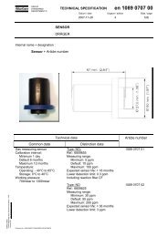
WORK ORGANIZATION<br />
Type of production, single,<br />
group, rigidly controlled,<br />
quality demands,<br />
psycho/physical factors<br />
Dose and distribution<br />
of physical<br />
and psychological<br />
loads<br />
OPERATOR<br />
Sex, age,<br />
physical<br />
measurements,<br />
fi tness, mental status<br />
Hand size, hand<br />
strength, arm length,<br />
precision, motion<br />
ent in terms of shape, center of gravity, weight,<br />
noise, lubrication requirements, vibration and<br />
other factors. Yet each tool is capable of install-<br />
ing a joint with the same torque.<br />
The selection of tool influences the user<br />
of the tool. In reality, you are unlikely to find<br />
yourself in a situation where you need to choose<br />
between all the different tool types. Therefore<br />
POWER TOOL<br />
Type, weight,<br />
balance, reactions,<br />
handles, trigger<br />
Ease of handling,<br />
load, acceptance<br />
WORKPLACE<br />
Standing, sitting,<br />
table, chair, light,<br />
fi xtures, component<br />
distribution<br />
Body posture, wrist<br />
posture, feed force / torque<br />
demands, exposure, noise<br />
vibration, dust<br />
Fig. 1.2 The workplace is a complex structure. All aspects however small affect the finished result.<br />
the question may seem academic. Nevertheless,<br />
it is an aspect worth bearing in mind.<br />
The selection of a power tool is an important<br />
parameter for workstation design. Ironically,<br />
the best power tool on the market will not trans-<br />
form a badly designed workstation into a safe,<br />
comfortable work area for the operator.<br />
11
12<br />
Work organization<br />
No organization is static. If operators<br />
at all levels are encouraged to improve<br />
their knowledge, the efficiency of the<br />
organization will gradually improve. An<br />
ongoing process where investments in<br />
Assembly work should be as varied as possible to avoid repetitive motions.<br />
machines and the workplace go hand-<br />
in-hand with operator training will be<br />
perceived as the natural state of things<br />
by the employees and form the founda-<br />
tion for a high level of job satisfaction.
Trends in modern<br />
work organization<br />
To be competitive in today’s market, a com-<br />
pany should be able to respond smoothly to<br />
its customers’ demands for different mod-<br />
els and mixes of products. This calls for a<br />
new approach to work organization and a<br />
number of new systems are being used by<br />
modern industry.<br />
These systems have certain common<br />
characteristics. For example, many produc-<br />
tion systems have now changed from the<br />
old type of “push” system to a “pull” system<br />
(order-based management).<br />
New types of production systems are<br />
usually more integrated than their pred-<br />
ecessors. This has been achieved by uniting<br />
the different departments; for example,<br />
design, marketing and production, to im-<br />
prove communication within the production<br />
system.<br />
Another characteristic of today’s produc-<br />
tion systems is flexibility. Operators are usu-<br />
ally multi-skilled and thus able to perform a<br />
number of different tasks within the group.<br />
The barriers between operators, mainten-<br />
ance staff, white-collar workers, engineers<br />
and marketing personnel are being broken<br />
down. Operators are expected to forge con-<br />
tacts with other personnel, both within and<br />
Modern production methods place greater<br />
demands on the individual operator.<br />
13
1<br />
outside the production system, and efficient<br />
networking is a growing trend.<br />
Many new systems have a learning<br />
organization in which employees are en-<br />
couraged to participate by expanding their<br />
personal skills. Active psychological in-<br />
volvement of the workers in the production<br />
system allows them to make major contribu-<br />
tions to the improvement of productivity,<br />
product quality and working conditions.<br />
Working conditions –<br />
an important factor<br />
Working conditions are another important is-<br />
sue in the improvement of work organization.<br />
Nowadays, ergonomic principles are<br />
used in work organization studies. In many<br />
modern industries, correct distribution of<br />
tasks between human beings and machines<br />
has eliminated the need for heavy physical<br />
work on the part of operators. In the new<br />
production systems, varying an operator’s<br />
tasks helps to eliminate disorders caused by<br />
highly repetitive, monotonous work tasks.<br />
The level of job satisfaction seems to be<br />
much higher in many of the new production<br />
systems.<br />
The 21st Century has started with the<br />
big Asian markets rapidly entering the<br />
competition. There is growing demand for<br />
Learning is a continuous process and an<br />
interchange of ideas and knowledge.<br />
decreased production costs in Europe and<br />
the USA. This can be seen, for example, in<br />
the trend to return to line production where<br />
group assembly was earlier tried. This poses<br />
a real challenge for the ergonomists. We<br />
want to keep the benefits that have been<br />
gained over the years in this new produc-<br />
tion environment.
Sitting assembly<br />
workstation<br />
The majority of workplaces have sitting<br />
workstations. Sitting is a good posture,<br />
particularly for high precision jobs.<br />
However, the sitting posture limits the<br />
operator’s reach and sometimes the task<br />
requires the operator to pick up compo-<br />
nents at the edge of his reach distance.<br />
If this movement becomes highly repeti-<br />
tive, there is always a risk of shoulder<br />
and neck problems. Sitting workstations<br />
should be designed so that the operator<br />
has to stand up and walk around from<br />
time to time. The human body was not<br />
designed to maintain the same posture<br />
for long periods of time.<br />
The operator should not be restricted to just one<br />
working position, such as sitting, for example.<br />
1
1<br />
A seated operator usually has good stability<br />
and is thus capable of performing tasks re-<br />
quiring precision or fine manipulative move-<br />
ment, especially if provided with armrests.<br />
Max 15 0<br />
Static load on the neck and shoulder muscles<br />
should be reduced where possible. The static load<br />
increases with the angle of the head in relation to<br />
the vertical plane.<br />
However, when seated, the operator has less<br />
mobility and is unable to apply the same<br />
degree of force.<br />
When applying ergonomics to the design<br />
of a sitting workstation, working postures<br />
and musculoskeletal load must be taken<br />
into account. This is particularly true for<br />
the low back, the shoulder, and the upper<br />
extremities. Ergonomic workstation design<br />
means careful study of the relationships<br />
between workstation, seat, tools and tasks<br />
to be performed (i.e., product design and<br />
method of manufacture), with the aim of<br />
improving working postures and reducing<br />
musculoskeletal load. The operator’s reach<br />
range and force capacity in a sitting position<br />
are also important design criteria.<br />
The work table<br />
and chair<br />
According to general ergonomic guidelines,<br />
working for long periods with the shoulders<br />
elevated or the arms fully extended should<br />
be avoided wherever possible. Work should<br />
be performed with the trunk upright and<br />
the head in an upright or slightly forward<br />
position, to avoid undesirable twisting. It is<br />
also important to provide sufficient legroom.<br />
Due to the anthropometric differences<br />
between individual operators, i.e., the
variations in physical measurements, few<br />
workstations will accommodate all workers<br />
ergonomically.<br />
For this reason, an important ergo-<br />
nomic feature of a sitting workstation is the<br />
adjustability of the chair and/or table. The<br />
workstation should be designed so that an<br />
operator can adjust it quickly and easily to<br />
his or her own physical measurements.<br />
Operators should be encouraged to adjust<br />
their workstations to the tasks undertaken.<br />
Fig. 1.3 Flexibility is a key factor.<br />
Reach ranges and<br />
force capacity<br />
To determine where parts or hand tools<br />
should be located or placed, it is necessary<br />
to consider the reach range. Naturally, reach<br />
ranges are limited by the physical measure-<br />
ments of the individual worker. Here, there<br />
are two individual concepts that a designer<br />
should be familiar with: (1) zones of conven-<br />
ient reach; and (2) the normal working area.<br />
Fig. 1.4 It is im-<br />
portant to realize<br />
the difference between<br />
the zone of convenient<br />
reach and the normal<br />
working area.<br />
60°<br />
Normal working area<br />
Maximum workin area<br />
Normal working area<br />
Zone of<br />
convenient reach<br />
A zone of convenient reach is a zone in<br />
which an object may be reached conveniently<br />
without undue exertion. The zone of conven-<br />
ient reach is determined by the length of the<br />
operator’s arm. The dimensions of a work-<br />
station layout are usually such that 95%<br />
of all workers at the workplace are able<br />
to reach the necessary points in the area<br />
17
1<br />
without stretching the trunk. The intersec-<br />
tion of a horizontal plane, such as a work<br />
table, with the zone of convenient reach de-<br />
fines what industrial engineers usually call<br />
the maximum working area. Within this<br />
area, there is a much smaller “normal work-<br />
ing area”, described by a comfortable sweep-<br />
ing movement of the upper limbs about the<br />
shoulder with the elbow flexed to 90 degrees<br />
or slightly less.<br />
When the elbow is flexed to 90 degrees<br />
and the upper arm is rotated at the shoul-<br />
der about its own axis, the comfortable<br />
limit of outward rotation is only about 30<br />
degrees.<br />
This factor, together with the average<br />
arm lengths of the workers at the work-<br />
place, can be used to determine the “normal<br />
working area”.<br />
Work postures<br />
As the arm moves between different loca-<br />
tions in the working area, the lengths of the<br />
arm muscles change. The length of a muscle<br />
is an important factor in its capability to<br />
generate tension. Extreme arm postures<br />
should be avoided. This factor should be<br />
considered in the design of workstations<br />
and selection of hand tools, particularly for<br />
operations requiring a degree of force.<br />
Muscle groups<br />
Different muscles have different capacities<br />
to generate tension. Correct task design<br />
will allow operators to generate higher<br />
force. For example, if self-tapping screws<br />
are to be tightened, a high feed force is<br />
required, therefore a pistol grip tool should<br />
be used. A pistol grip is superior to a<br />
straight grip in terms of transferring feed<br />
forces, because the muscle groups used<br />
to flex the upper arm have a higher force<br />
generating capacity than those used to<br />
extend it.<br />
Workpiece and tool selection<br />
The working posture is, to a large extent,<br />
determined by the workpiece. To improve<br />
poor working postures (where suitable tools<br />
are already being used), the positioning of<br />
the workpiece and/or the method of manu-<br />
facture should be examined. A rotatable<br />
fixture may be needed at some assembly<br />
stations where tasks are carried out in<br />
different directions.<br />
When there is a considerable distance<br />
between the top height and bottom height<br />
of the tasks performed, an adjustable<br />
working height may be considered.<br />
A tiltable work surface allows a better<br />
head posture.
Load-reducing measures<br />
In many industrial situations, reducing load<br />
is not an easy task due to the constraints of<br />
tool/product weights, or because the nature<br />
of the tasks or the work organization result<br />
in repetitive or extended load situations. In<br />
such cases, alternative load-reducing meas-<br />
ures may be considered. Commonly used<br />
load reducing devices include arm-rests,<br />
arm slings, and weight balancers.<br />
Arm-rests may be used for assembly or<br />
repair tasks where the arm has to be held<br />
away from the body and is not moved ex-<br />
tensively during the work cycle. The height<br />
should be properly adjusted to suit the<br />
individual operator and to provide the best<br />
support for the arms and for the tasks un-<br />
dertaken. Arm-rests should be well padded,<br />
they should permit easy movement of the<br />
forearm and have no hard edges that could<br />
cause discomfort. The arm-rests should be<br />
located near the front surface of the work-<br />
station, but should be easily adjusted to<br />
suitable positions for the variety of tasks an<br />
operator may have to do. They should tilt<br />
without requiring manual re-adjustment.<br />
Armrests on a chair are best positioned<br />
slightly below elbow height when sitting, if<br />
a relaxed posture is to be achieved. Wrist<br />
supports can also be useful for complex<br />
assembly work, to stabilize the hands.<br />
The selection of handle<br />
type can have an adverse<br />
effect on posture.<br />
1
20<br />
The arm sling as a preventive measure<br />
When there is a risk of prolonged static<br />
load on the shoulder region and the work is<br />
performed within a wider radius so that the<br />
use of arm-rests is not feasible, arm slings<br />
are sometimes used. The lift force of an<br />
arm sling should be individually adjusted<br />
to about 20% of the total arm weight (about<br />
5% of the total body weight). The introduc-<br />
tion of arm slings should not interfere with<br />
the task being performed. If this is the case,<br />
other alternatives should be explored.<br />
Although more beneficial for operators<br />
with musculoskeletal symptoms, the arm<br />
sling should generally be regarded as a<br />
preventive measure rather than as an aid<br />
to rehabilitation.<br />
Weight balancers reduce fatigue<br />
The weight of a hand tool, particularly<br />
a power tool, imposes limitations on the<br />
length of time that an operator can per-<br />
form the task, while reducing the degree of<br />
precision that the operator can achieve. In<br />
general, any tool weighing more than 2.5 kg<br />
that has to be operated while supported by<br />
the arms, and that has to be held out from<br />
the body in an awkward posture should be<br />
provided with a “weight balancer”.<br />
Arm slings compensate for the weight of the arms,<br />
and reduce tension in the shoulder-neck area.
Standing workstation<br />
A standing workstation allows an opera-<br />
tor to apply higher forces and provides<br />
him with greater mobility than a sitting<br />
workstation. A number of ergonomic<br />
considerations can help the operator<br />
use the standing working position to its<br />
greatest advantage and minimize the<br />
potential risks of standing workstations.<br />
To allow good postures for different operators, the<br />
height of the workstation should be adjustable.<br />
A standing workstation may be the best<br />
alternative in the following circumstances:<br />
(1) considerable muscle force is needed;<br />
(2) frequent high, low or extended reaches<br />
are required; (3) downward force must be<br />
exerted; (4) knee clearance is limited for<br />
a seated operator; (5) the workpiece is too<br />
high to take both the upper arm posture<br />
and the knee space into consideration. The<br />
overall aim of the ergonomic design princi-<br />
ples for a standing workstation is the same<br />
as for the sitting workstation, i.e., to avoid<br />
unnatural postures.<br />
Extreme working postures<br />
In some standing work situations, it is<br />
not possible to achieve acceptable working<br />
postures. For example, many construction<br />
operations involve working above shoulder<br />
level. In such situations, it is important to<br />
reduce the load on the static muscles and<br />
to shorten the duration of each operation.<br />
The static muscle load can be lowered by<br />
reducing the weight of the tools and by<br />
21
22<br />
Extreme working postures in real life.<br />
holding the tool close to the body (reducing<br />
the amount of arm leverage applied). The<br />
duration of individual operations can be<br />
shortened by shifting frequently between<br />
tasks which use different muscle groups.<br />
Here, ergonomic administrative controls are<br />
needed to reduce the risk of static muscle<br />
load over long periods.<br />
Providing the operator with the correct<br />
working technique is also an important<br />
basic factor in reducing the risk of musculo-<br />
skeletal injuries. When lifting from the floor,<br />
the operator should be encouraged to bend his<br />
or her knees instead of the low back.<br />
Applying force<br />
when standing<br />
In standing position, high forces can usually<br />
be generated with the help of the body weight.<br />
Therefore it is important that the standing<br />
workstation is designed to allow the operator<br />
to use his body weight when a high degree<br />
of force needs to be applied. For example,<br />
in performing sanding and polishing tasks,<br />
the work surface should be in the horizontal<br />
plane, slightly below elbow level. This is par-<br />
ticularly important during lengthy operations<br />
such as sanding and polishing. Otherwise, the<br />
relatively weak arm muscles will be over-<br />
exerted and the work performance impaired.<br />
A B<br />
Fig. 1.5 Using the right working technique. This<br />
figure shows two situations: (A) lifting an object<br />
from the floor by bending the back – the wrong<br />
technique; (B) lifting an object from the floor by<br />
bending the knees – the right technique, if your<br />
knees can take it!
Adjustable platforms are useful in this<br />
respect, since they can be set to the working<br />
height which allows the operator to apply<br />
maximum force. The adjusting mechanism<br />
should allow the operator to make the ad-<br />
justment quickly and easily. Otherwise,<br />
the operator may be reluctant to make the<br />
necessary adjustments. In some situations,<br />
horizontal work surfaces may not be feasible.<br />
A working height slightly above elbow level<br />
is usually needed to obtain an acceptable<br />
working posture for horizontal force applica-<br />
tions. When high feed forces are demanded,<br />
such as in some drilling, chipping and scaling<br />
tasks, the operator should take advantage of<br />
his body weight by leaning slightly forward.<br />
Sufficient standing space should be provided<br />
in order to achieve a stable standing posture<br />
when applying force. Where a high degree<br />
of horizontal force is to be applied (> 200 N),<br />
friction between the shoes and the floor<br />
should also be taken into consideration, to<br />
avoid slipping. In the ergonomically planned<br />
workplace, care is taken to reduce the risk of<br />
On modern production lines cars can often be adjusted in height to allow good postures for the assembly<br />
operators. This is especially important where high feed forces are applied.<br />
23
2<br />
Working with high feed forces requires the<br />
operator to lean forward slightly in order to<br />
make use of his body weight.<br />
an operator slipping or tripping over. An op-<br />
erator’s footwear should be selected accord-<br />
ing to the degree of horizontal force to be<br />
applied and the floor surface. Special atten-<br />
tion should be paid to the slipperiness of the<br />
floor surface when dry, and when wet from<br />
spilled materials or cleaning operations.<br />
Non-slip coatings, such as paint containing<br />
sand, have successfully reduced the risk of<br />
“slip-and-trip” accidents in areas where wet<br />
floors are common. However, increased<br />
friction may make walking or manually<br />
maneuvering a vehicle difficult.<br />
Operator comfort in the<br />
standing workstation<br />
Shoes with well-cushioned insteps and<br />
soles, and/or rugs or mats can be used in<br />
standing workplaces to improve operator<br />
comfort. It has been shown that working in<br />
a standing position for prolonged periods<br />
causes discomfort due to (1) prolonged static<br />
muscular effort in the feet, knees and hips;<br />
and (2) increased hydrostatic pressure of<br />
the blood in the veins of the legs, and<br />
general restriction of lymphal circulation<br />
in the lower extremities.<br />
It is, therefore, important that the stand-<br />
ing operator is provided with the facilities to<br />
sit down frequently and rest his or her leg
On modern assembly lines considerable effort is invested in finding safe solutions for work tasks that would<br />
otherwise place heavy loads on the assembly operator, while requiring him or her to adopt awkward postures.<br />
muscles. From a physiological and orthopedic<br />
point of view, a workstation which allows the<br />
operator to sit or stand, as he wishes, is highly<br />
recommended. Since standing and sitting<br />
impose load on different muscles, variations<br />
between the two positions will reduce the risk<br />
of statically loading single muscle groups.<br />
Varying the working position between<br />
standing and sitting can also stimulate the<br />
supply of nutrients to the intervertebral<br />
discs, which is also beneficial to the operator’s<br />
health. It is also crucial to design the worksta-<br />
tion so that the operator can walk around it<br />
rather than stand in one place. During walk-<br />
ing, the muscles of the legs act as a pump,<br />
which compensates for the hydrostatic<br />
pressure of the veins by actively propelling<br />
blood back towards the heart. It is also help-<br />
ful to provide a foot rail (foot-rest) so that the<br />
operator can rest his feet, one at a time. This<br />
varies the hydrostatic pressure of the veins<br />
and improves blood circulation in the legs.<br />
2
2<br />
Working areas of a<br />
standing workstation<br />
The forward reach area is determined by<br />
the zones of convenient reach or the “normal<br />
working area” as discussed in the section on<br />
the sitting workstation.<br />
Occasionally, tasks may lie outside the<br />
zones of convenient reach. An operator may<br />
have to extend his reach by leaning, stretch-<br />
ing or stooping. Any one of these postures can<br />
easily produce fatigue if assumed frequently or<br />
maintained for periods longer than one minute.<br />
We´re all different!<br />
If the arm and forearm are elevated to a nearly<br />
horizontal position when reaching forward,<br />
a load of only 56 N in the hands will create a<br />
load moment at the shoulder equivalent to the<br />
maximum flexor strength moment predicted for<br />
the average female. A 115 N load will be equal<br />
to the shoulder lifting strength of the average<br />
male. Therefore, if such situations occur, the<br />
task should be of an occasional nature, such as<br />
activating a switch. The physical strain im-<br />
posed on the operator by such extended reaches<br />
can be reduced by ergonomic workstation<br />
design.<br />
Designing a standing workstation becomes<br />
an even more challenging task, when taking<br />
into account the wide spread in body measures.<br />
Workstations that are used by many differ-<br />
ent operators must be made adjustable and<br />
the operators must be instructed to adjust the<br />
workstation to fit their size.
Standing assembly<br />
line workstation<br />
Working in a standing position along an<br />
assembly line involves a great deal of<br />
walking. Although this in itself is good,<br />
there is a tendency for operators to try<br />
to work themselves upstream in order to<br />
allow time to correct any errors without<br />
interfering with the work of operators further<br />
down the line. This is a stress situation.<br />
Assembly work<br />
organization<br />
An assembly line which is equipped with<br />
ergonomically designed hand tools, and<br />
where interactions between tools, work-<br />
stations and tasks have been carefully<br />
planned, will improve working postures<br />
and reduce mechanical load on the operators.<br />
An example of this approach in the auto-<br />
motive industry is the general decision to avoid<br />
work above shoulder height. Thus, the car<br />
Sometimes tools are used in ways the designers<br />
never even thought of.<br />
27
2<br />
body is lifted or tilted, or the power tool is<br />
suspended in an articulated arm.<br />
Rig assembly from above<br />
All components to be assembled under the<br />
chassis plate, such as the engine drive shaft,<br />
exhaust system, wheel suspension, hydraulic<br />
pipes and so on, are first assembled in a rig<br />
from above.<br />
In the automotive industry much effort is put into avoiding tasks that<br />
would otherwise require work above shoulder height.
Later, the chassis plate is added to the<br />
assembly, and the whole package is automat-<br />
ically bolted together with the use of a large<br />
number of nutrunners in a rig assembly.<br />
This approach is essential if the risk<br />
of work-related musculoskeletal disorders<br />
among the operators is to be reduced. How-<br />
ever, adopting this approach does not guar-<br />
antee that the risk is eliminated. Scientific<br />
research has proved that workers exposed to<br />
even very low external mechanical load (e.g.<br />
as low as 1% of their maximum force capac-<br />
ity) may still develop musculoskeletal dis-<br />
Rig assembly of all components under the car.<br />
orders in situations where the external load<br />
is continuous and prolonged. The solution to<br />
this problem may be to reduce the monotony<br />
of the external load by introducing a more<br />
varied load pattern (physical variations).<br />
In the traditional assembly line organiza-<br />
tion, physical variations may not be intro-<br />
duced easily. This is because the basic prin-<br />
ciple of the traditional assembly system is to<br />
assign simple repetitive tasks to individual<br />
assembly workers. Each operator is therefore<br />
subjected to repetitive, monotonous external<br />
load. It has been proposed that assembly<br />
2
30<br />
The team is an important factor in production.<br />
operators in such working conditions should<br />
be able to take frequent pauses and switch to<br />
other tasks in order to relax their muscles.<br />
Modern methods of organizing assembly<br />
work seem to offer greater potential for vary-<br />
ing physical exposure on individual operators<br />
than the traditional assembly line concept.<br />
Nowadays, markets require flexible produc-<br />
tion systems able to meet changing customer<br />
demands. To achieve this, production plans are<br />
based on orders already placed by customers.<br />
This requires a new type of assembly concept<br />
and, in recent years, in some factories the<br />
scope of tasks allotted to each operator has<br />
been successfully broadened.<br />
In a flexible production system assem-<br />
bly operators have greater responsibility for<br />
productivity, product quality and workflow.<br />
One trend is that more and more components<br />
are assembled elsewhere, and even designed<br />
by a subcontractor to the production unit. Less<br />
work is done along the line, which makes it<br />
easier to design good workstations. The sys-<br />
tems usually encourage the assembly staff to<br />
become multi-skilled, i.e., increase their skills<br />
to include a number of different operations.<br />
Bearing ergonomic principles in mind, this<br />
new type of assembly organization enables<br />
operators to vary their physical exposure by<br />
shifting between tasks in the assembly system.
2MAIN TYPES OF<br />
POWER TOOLS
32<br />
Grinders<br />
Grinders and sanders are essentially<br />
the same machines used with different<br />
inserted tools for different purposes.<br />
Power outputs can range from 0.1 to 4.5<br />
kW. Weights vary from a few tenths of a<br />
kilogram to several kilograms. High<br />
power is always a risk factor and opera-<br />
tors must be trained to use the tool safely.<br />
Where are they used?<br />
Grinding machines are used where material<br />
removal is the primary task – from cutting<br />
off pouring ingate, and heavy grinding on<br />
large components, to precision die grinding.<br />
Grinding machines are suitable for rough<br />
or fine sanding of castings. They can be<br />
used on huge constructions, such as offshore<br />
platforms, or for repairing the bodywork of<br />
damaged motor vehicles. Machines of this<br />
type will put a fine finish on a plastic boat<br />
or give wooden furniture a surface that<br />
makes it a pleasure to use.<br />
Before using high powered grinders, operators<br />
should be trained to avoid unnecessary risks of<br />
exposure to injury, noise and vibration.
Working environment<br />
Grinding and sanding machines are gener-<br />
ally found where any form of mechanical<br />
work is being undertaken.<br />
Since every work situation is unique, it<br />
is impossible to predict with any precision<br />
how a machine will be used, or the degree of<br />
physical exposure that will be experienced<br />
by the operator.<br />
The working environment can be any-<br />
thing from a clean assembly shop, where<br />
grinders are used for small finishing tasks,<br />
to a noisy, dirty environment where very<br />
heavy grinding is taking place.<br />
Design for good ergonomics<br />
Since a natural grip is always the most com-<br />
fortable grip, handles and triggers should be<br />
designed with this in mind. It should also be<br />
easy for the user to change his grip on tool<br />
– this helps to distribute the load and avoid<br />
local muscular fatigue.<br />
Although the operator may not need to<br />
apply much muscle power to perform his task,<br />
during prolonged working periods the load<br />
quickly becomes a static load that can be ex-<br />
hausting. Most grinding tools are held in a two-<br />
handed grip that provides stability and distrib-<br />
utes the load evenly between both hands.<br />
The lever trigger is a feature of nearly<br />
all grinders and sanders. The operator can<br />
either operate the trigger with his fingers or<br />
with the palm of his hand.<br />
Safety<br />
Since the power outputs of tools of this type<br />
can vary from 0.1 to 4.5 kW, there are always<br />
risks involved in using the machines.<br />
The worst accident scenario would be the<br />
disintegration of a grinding wheel. Fortun-<br />
ately, such occurrences have been rare. But<br />
if it did happen, and there was no guard in<br />
place on the machine, a disintegrating wheel<br />
could fatally injure a person in the vicinity. So<br />
the guard must be in place at all times.<br />
You could always argue that tools of this<br />
type should be supplied with permanently<br />
fixed guards. But they are normally designed<br />
for use with depressed center wheels, cut-<br />
ting off wheels, cup wheels, brushes and fiber<br />
discs. In the latter application the machine<br />
works as a sander and does not require a<br />
guard, but each of the other applications men-<br />
tioned requires a different guard. For this<br />
reason, <strong>Atlas</strong> <strong>Copco</strong> supplies grinders with<br />
guards assembled, but the guard can be<br />
exchanged for a different type when the task<br />
changes.<br />
It is extremely important that the opera-<br />
tor is fully aware that the speed marked on<br />
the machine should never exceed the speed<br />
marked on the wheel.<br />
33
34<br />
HanDle DeSiGn<br />
The hand grips on grinding machines are<br />
normally round or oval in shape. The cir-<br />
cumference is generally less than 120 mm,<br />
except where the handle is integrated into<br />
the machine housing. No machine has han-<br />
dles longer than 130 mm and no handle is<br />
shorter than 100 mm. The support handle is<br />
rounded at the end, allowing the tool to be<br />
held in a number of different ways.<br />
The support handle should preferably be<br />
adjustable so that different angles can be set<br />
between the support handle and the trigger<br />
handle. Thus, the operator can customize<br />
the machine to suit himself and the task.<br />
A visco-elastic layer on the handle in-<br />
creases the friction between hand and han-<br />
dle for optimum maneuverability. The layer<br />
should be designed to allow good ventilation<br />
of the hand. A lever trigger with a safety<br />
lock prevents the tool from being activated<br />
unintentionally.<br />
external loaD<br />
When grinding, the operator does not need<br />
to apply much force or grip the tool handles<br />
excessively tightly. Yet using the right tool<br />
for the job and working at a correctly de-<br />
signed workstation are still very important<br />
since grinding is usually a long, drawn-<br />
out operation. Operator fatigue is usually<br />
caused by the torque generated by the reac-<br />
tion force in the process and absorbed by the<br />
operator’s wrist.<br />
For rough grinding and cutting, the ex-<br />
tra power of the large machines is utilized,<br />
giving high process forces. However, the<br />
additional weight of these machines places<br />
an extra load on the operator.<br />
The tools are designed so that only low<br />
trigger forces are required. These are gently<br />
conveyed into the hand by the lever trigger.<br />
WeiGHt<br />
The weight of the machine is often regarded<br />
as a positive factor, particularly when<br />
grinding on horizontal surfaces. It can be<br />
troublesome when performing vertical and<br />
over-head grinding tasks, but awkward<br />
work postures of this type should be avoided<br />
in any case.<br />
Nevertheless, if you are working on the<br />
bottom of a ship’s hull, such postures are<br />
difficult to avoid.<br />
As a general rule, our tools are designed<br />
to be as light as possible. The dynamic<br />
forces to which the operator is exposed due<br />
to the motion of the machine while grinding<br />
are small, since acceleration is low in the<br />
normal motions used.
teMPeratUre<br />
Low temperatures in the handles of<br />
pneumatic grinders can sometimes be<br />
annoying and are due to the expansion of<br />
compressed air in the motor.<br />
The outlet air should be guided away<br />
from the handles. When grinding for long<br />
periods, the entire grinder housing can<br />
grow cold and the low temperature can be<br />
transmitted to the handles. These must be<br />
covered with an insulating material.<br />
The opposite problem can occur in elec-<br />
trical grinders where the motor heats up<br />
during use. Machines with angle gears also<br />
have a tendency to get hot.<br />
SHoCK reaCtion<br />
The handles of a grinding machine transmit<br />
only a small amount of jerk. When the<br />
machine is started, forces act on its distrib-<br />
uted mass or inertia. The acceleration se-<br />
quence takes about 0.5 sec. for a pneumatic<br />
machine, depending on wheel size. The<br />
operator can cope easily with the reaction<br />
force and the starting time is so long that it<br />
can hardly be considered a jerk.<br />
For large electric machines equipped<br />
with on/off triggers, however, the operator<br />
must be prepared for the acceleration<br />
forces.<br />
ViBration<br />
The level of handle vibration for a grinder<br />
in use depends on the tool fitted. The main<br />
source is the imbalance of the wheel. A<br />
wheel that is slightly out of true will also<br />
add to the vibration value. The declared<br />
value is measured using an artificial wheel<br />
with a defined imbalance in accordance with<br />
an international standard. The vibration is<br />
often measured halfway along the length of<br />
the handle.<br />
noiSe<br />
The actual grinding process is the dominant<br />
noise source. A grinder driven by compressed<br />
air emits motor noise, irrespective of whether<br />
it has a vane or a turbine motor. The noise<br />
typically produced by a vane motor has a<br />
dominating frequency corresponding to the<br />
rotational speed of the motor multiplied<br />
by the number of vanes in the motor. The<br />
turbine generates broad band air stream<br />
noise. In electric tools, noise is generated by<br />
the gears and by the fan used to create the<br />
cooling air flow.<br />
The declared value for noise in the<br />
operator’s instructions is measured with the<br />
machine running free, since process noise<br />
is unique for every workplace and therefore<br />
cannot be predicted.<br />
35
36<br />
DUSt anD oil<br />
Although the machine itself does not gener-<br />
ate dust, the exhaust or cooling air whirls<br />
up a certain amount of dust. Other sources<br />
are the process and the general dust situa-<br />
tion in the working environment.<br />
To lower the operator’s exposure to dust,<br />
a ventilated grinding booth can be used. A<br />
more efficient way is to equip the grinder<br />
with a dust collector and connect it to a spot-<br />
suction system.<br />
Many vane motor driven grinders require<br />
lubrication and oil is added to the air inlet.<br />
Hand-held grinding is often more flexible than<br />
using numerically controlled machines.<br />
In machines with low outlet velocities the oil<br />
will leave the outlet in the form of drops.<br />
A high velocity outlet atomizes the oil<br />
which is ejected as an airborne mist. How<br />
this affects the operator depends on the<br />
efficiency of the ventilation system in the<br />
workplace. One way to reduce physical<br />
exposure is to provide the air inlet with a<br />
dosol lubricator, limiting the amount of oil<br />
entering the machine. Machines driven by<br />
turbines, and electrically driven grinders,<br />
are oil free.
Drills<br />
One of the oldest hand-held tools, drills<br />
are used in practically all industries to<br />
make holes in a variety of sizes, from less<br />
than 1 mm in diameter up to more than<br />
50 mm. Using a drill is not regarded as<br />
a high physical risk to the operator.<br />
Where are the<br />
tools used?<br />
Drills are used in almost all production<br />
situations. The use of drills has changed<br />
over the years. A century ago, ships were<br />
warm-riveted. Workers expended huge<br />
amounts of physical effort drilling thousands<br />
of holes, often with diameters of more than<br />
30 mm, to prepare the plates for riveting.<br />
Today, holes are drilled in aircraft fuse-<br />
lages in preparation for riveting. However,<br />
these holes are only a few millimeters in<br />
diameter and the muscle effort required to<br />
produce them is acceptable.<br />
Drilling is a common operation in the<br />
aerospace industry.<br />
37
38<br />
Working environment<br />
In general, drills have a low impact on the<br />
working environment, particularly the<br />
small models. Large drills can be somewhat<br />
noisy. Most drills do not require lubrication.<br />
Design for good ergonomics<br />
The load on the operator depends on the size<br />
of the hole to be drilled. If a larger hole is to<br />
be drilled, more feed force must be applied<br />
to the machine by the operator. Larger holes<br />
can be pre-drilled to reduce the feed force.<br />
The type of grip chosen will influence<br />
the operator’s posture. A drill with a pistol<br />
grip conveys feed forces more efficiently than<br />
straight or angle grip drills.<br />
The handle must be designed to mini-<br />
mize the torque absorbed by the wrist when<br />
high feed forces are needed.<br />
The pistol grip should allow the operator<br />
to change his hold on the machine. He should<br />
hold the machine lower down the handle<br />
when applying a small feed force and higher<br />
up when high feed force is required. The high<br />
position should result in a straight line from<br />
the center line of the machine to the bones<br />
in the operator’s forearm. The torque in the<br />
operator’s wrist should be kept as low as<br />
possible at all times.<br />
The straight handle should only be<br />
used when low feed forces are required,<br />
particularly where a vertical hole is to be<br />
drilled in a workpiece. If high feed forces<br />
are necessary, a pistol grip machine may be<br />
used, provided the operator can work with<br />
his wrist held straight. If the hole requires<br />
a bent wrist posture, the position of the<br />
workpiece should be rearranged so that the<br />
operator can work with a straight wrist.<br />
The combination of bent wrist and high feed<br />
forces should always be avoided.<br />
The angle grip is used mainly for drill-<br />
ing in cramped spaces. The feed force<br />
needed should preferably be applied using<br />
both hands.<br />
The wrist’s capability to provide ulnar<br />
flexion torque is limited and one-handed<br />
operation of angle drills should be avoided.<br />
Safety<br />
Drills are not generally a risk. However, if<br />
the operator holds the drill bit and starts the<br />
tool he will damage his hand. Some drills<br />
have a guard covering the chuck, but the<br />
drill bit cannot be guarded easily. The guard<br />
allows a comfortable two-handed grip.<br />
When working with larger drill bits,<br />
there is always the risk of a jerk when the<br />
drill bit penetrates the workpiece, resulting<br />
in a shock reaction which is absorbed by the<br />
operator’s wrist. Most of the feed force is<br />
applied to the point of the bit to help it work
its way through the material. When the point<br />
penetrates, the operator should reduce the<br />
feed force. If the drilling cycle does not allow<br />
time for this, the drill bit will not cut a clean<br />
hole and may jam. Problems of this kind can<br />
be avoided by using a support handle.<br />
HanDle DeSiGn<br />
The pistol grip for drills was the first grip<br />
designed using the human anatomy as a<br />
basic criterion. The angle of the handle to<br />
the center line of the machine was chosen<br />
so that the operator could keep his wrist<br />
straight when holding the tool. The torque<br />
absorbed by the wrist from the feed force<br />
should be kept to a minimum. The handle<br />
should be long enough to accommodate the<br />
entire hand. The handle width was selected<br />
so that the fingertips almost reached the<br />
base of the thumb when the operator grasped<br />
the tool tightly.<br />
external loaD<br />
Feed forces are the greatest load factor<br />
when drilling. Machines designed for large<br />
diameter bits are provided with planetary<br />
gears. These add weight to the tool, moving<br />
the center of gravity away from the opera-<br />
tor’s wrist and increasing the radial flexion<br />
torque. This is a design dilemma. The op-<br />
erator needs to grasp the handle high up in<br />
order to minimize the wrist torque from the<br />
feed force. A pistol grip which allows this<br />
is a good choice. At the same time, a pistol<br />
grip with the handle at the end of the tool<br />
will transmit torque to the wrist due to the<br />
weight of the machine.<br />
WeiGHt<br />
As mentioned previously, weight causes<br />
torque to be transmitted to the wrist. The<br />
operator is exposed to this factor when he<br />
moves the tool to and from the workpiece.<br />
To solve this problem, the tool is often<br />
suspended in a balancer which, particularly<br />
in the case of COL type balancers, renders<br />
the machine virtually weightless. Thus, at<br />
a typical workstation, the weight of the tool<br />
does not expose the operator to dynamic<br />
forces.<br />
teMPeratUre<br />
The exhaust air from the vane motor is cold<br />
but, since the air flow is directed away from<br />
the hands, this causes no discomfort to the<br />
operator. The temperature of the actual<br />
machine is proportional to the power it<br />
uses and in most applications the drill has<br />
a greater power capacity than it needs to<br />
cover short power peaks. Thus, the machine<br />
does not become cold enough to cause opera-<br />
tor discomfort.<br />
39
40<br />
SHoCK reaCtion<br />
Sudden changes in torque from the machine<br />
can occur when the drill bit penetrates the<br />
workpiece. These torque peaks cannot be<br />
fully predicted and the best way to combat<br />
the problem is to use a support handle.<br />
ViBration<br />
In drills vibration levels are low and no test<br />
code has been developed for tools of this<br />
type. The manufacturer’s only obligation in<br />
this respect is to check that the vibration<br />
value, when drilling, is below 2.5 m/s 2 and<br />
to state that information in the operator’s<br />
instructions. If a bent drill bit is used, how-<br />
ever, the vibration can be considerable.<br />
noiSe<br />
All drills are provided with mufflers. In most<br />
cases, the process itself is not noisy. There-<br />
fore the level of noise to which the operator is<br />
exposed is the declared noise level according<br />
to the definition of the worksituation pro-<br />
vided by the noise measurement code.<br />
DUSt anD oil<br />
Drilling is a cutting process which produces<br />
long chips and, since these will not usually<br />
be airborne, no dust is created. However,<br />
when drilling in composite materials, such<br />
as carbon-reinforced plastic, the operation<br />
A small, modern drill must be designed to give<br />
the operator a choice between high and low grip.<br />
can result in minute airborne carbon fibers.<br />
These can penetrate electronic equipment<br />
and cause short-circuiting.<br />
This problem can be solved by equipping<br />
the machine with a dust collector connected<br />
to a spot suction system. Most drills are<br />
designed to run without lubrication.
Percussive tools<br />
Percussive tools use the blow energy<br />
from an accelerated piston to create high<br />
forces. The high forces can be used to<br />
chip off steel or to set a rivet. Using the<br />
tool may, however, involve risk of injury<br />
from noise and vibration.<br />
Vibration controlled riveting hammers<br />
and bucking bars are frequently used in<br />
the aerospace industry.<br />
Where are the tools used?<br />
There are three different types of percussive<br />
tools: chipping hammers, scalers, and rivet-<br />
ing hammers. The first two are commonly<br />
used in foundries, while the riveting hammer<br />
is mainly used in the aerospace industry.<br />
Since percussive tools are very effective they<br />
are commonly used for a variety of other<br />
applications, from the worker assembling<br />
guide pins in engine blocks to the sculptor<br />
chipping away at raw material in his studio.<br />
Working environment<br />
High noise levels are a typical problem with<br />
percussive tools. The machine noise can be<br />
muffled, but noise from the main source, the<br />
process, is difficult to reduce in a way that<br />
is physically acceptable to the operators.<br />
Vibration values are also high for per-<br />
cussive tools, in particular from the inserted<br />
tool. There is a general rule that the chisel<br />
in a chipping hammer, for example, should<br />
not be touched when the tool is being<br />
operated. Easy to say, but difficult in<br />
41
42<br />
practice. Sometimes the chisel has a round<br />
neck and the operator needs to guide it<br />
manually. Technically, this is to make the<br />
blow end flexible when cleaning a casting.<br />
From the point of view of safety, it is not<br />
good practice.<br />
Design for good ergonomics<br />
Modern machines are provided with muf-<br />
flers. When carrying out light cleaning of<br />
sand burnings on castings, the efficiency of<br />
the muffler can make a difference, but<br />
usually the process noise dominates.<br />
Control of vibrations in percussive tools<br />
has been more successful. Several methods<br />
have been used – for example, reducing the<br />
oscillating forces acting on the machine<br />
mass, or designing an isolation system<br />
which screens off the operator from the<br />
vibrating tool.<br />
For chipping hammers, where the pro-<br />
cess calls for high feed forces, the bow grip<br />
handle is often used to minimize the torque<br />
absorbed by the wrist. The trigger force and<br />
the feed force are in alignment and the trig-<br />
ger is often thumb-operated.<br />
When using percussive tools, the work-<br />
ing posture often remains the same for long<br />
periods of time. This may lead to muscle<br />
overload and fatigue due to static forces act-<br />
ing on the hand-arm system.<br />
Safety protection<br />
Ear defenders, safety goggles and gloves are<br />
strongly recommended. Research is continu-<br />
ously being conducted into the development<br />
of anti-vibration gloves. At present such<br />
gloves are ineffective against the low fre-<br />
quency vibrations emitted by these tools.<br />
Operators working in heavy industry should<br />
wear protective headgear.<br />
To prevent the operator from holding<br />
the chisel, the machines are provided with<br />
a retainer and, in many cases, a hand grip<br />
that can be moved along the chisel.<br />
HanDle DeSiGn<br />
The open or closed bow grip, or D handle,<br />
is a typical feature of chipping hammers.<br />
Riveting hammers and scalers often have<br />
straight or pistol grips. Chipping hammer<br />
handles are designed to allow high feed<br />
forces to be applied for long periods. The<br />
trigger is thumb-operated and the trigger<br />
force is in alignment with the feed force.<br />
Riveting hammers are designed for high<br />
precision and, in principle, one working<br />
posture. The trigger function on these tools<br />
allows one-blow-per-cycle operation.<br />
external loaD<br />
During a chipping operation high feed forces<br />
may be needed, while the posture often
emains the same. This loads the muscles of<br />
the upper arm with static forces. Undamped<br />
tools have high vibration values, causing<br />
greater tension of the muscles and increas-<br />
ing the percentage of maximum voluntary<br />
constriction (MVC). Scalers and riveting<br />
hammers require only low or moderate feed<br />
force and, even used for long periods, scal-<br />
ers represent a low level of physical expo-<br />
sure for the operator. As regards riveting<br />
hammers with higher feed forces, the total<br />
exposure per day is less than 20 minutes,<br />
therefore physical exposure is low.<br />
WeiGHt<br />
Tool weight is often a positive factor since it<br />
keeps the vibration value low and contrib-<br />
utes to the feed force. Percussive tools are<br />
moved so slowly that they do not expose the<br />
operator to any dynamic forces.<br />
teMPeratUre<br />
Percussive tools are full-pressure machines.<br />
In other words, there is very little expansion<br />
of the compressed air in the cylinders. There-<br />
fore the temperature of the machine does not<br />
fall low enough to cause operator discomfort.<br />
On the other hand, if a chipping hammer is<br />
used for long periods, the chisel will become<br />
hot to the touch. But, as stated before, the op-<br />
erator should not hold the chisel in any case. Scalers are commonly used in welding operations.<br />
43
44<br />
SHoCK reaCtion<br />
These tools do not give any shock reaction.<br />
ViBration<br />
There are at least three sources of vibra-<br />
tion in a percussive tool: the oscillating<br />
force that drives the piston, the shock wave<br />
transmitted to the machine from the chisel,<br />
and the vibration of the workpiece trans-<br />
mitted back to the machine. These sources<br />
can be counteracted at the design stage<br />
as described in the chapter Evaluation of<br />
Power Tools: Vibration.<br />
noiSe<br />
The basic principle of percussive tools is to<br />
create a shock wave that travels down the<br />
chisel or die to strike the casting or rivet with<br />
enough force to cause plastic deformation. The<br />
shock wave has a duration of less than 100 µs.<br />
This process involves very high frequencies<br />
and when these hit a structure many natural<br />
frequencies are excited, emitting broad band<br />
noise. High forces give high noise levels.<br />
DUSt anD oil<br />
Chipping and rust cleaning can create a<br />
lot of dust. In other words, the operator’s<br />
exposure to dust depends very much on the<br />
type of work in progress. The machine can<br />
be equipped with a dust collector connected<br />
to a spot-suction system.<br />
Percussive tools require very little lubri-<br />
cation since the piston moves back and forth<br />
in a very smooth cylinder without gener-<br />
ating heat. Only a minimal amount of oil<br />
leaves the tool with the exhaust air.
Screwdrivers<br />
Screwdrivers are used for the assembly of<br />
a variety of products, such as dishwashers,<br />
refrigerators, washing machines, electronic<br />
equipment and medical instruments, to<br />
name just a few. A clean indoor environ-<br />
ment, careful selection of hand tools and<br />
ergonomically designed workstations will<br />
result in a low level of physical risk for the<br />
workers, provided that the work is organi-<br />
zed to avoid frequent repetition.<br />
For modern pistol grip screwdrivers, the air inlet<br />
can be located on the top of the tool to simplify<br />
installation in balancers.<br />
Where are the tools used?<br />
Screwdrivers are used to assemble parts<br />
in designs where the products need to be<br />
dismantled easily for repair and service. A<br />
typical assembly operation could be mass<br />
production of a DVD player on an assembly<br />
line where a few screws are tightened at<br />
each workstation. It could also be the total<br />
assembly of a food processor by one opera-<br />
tor. Consumer goods have relatively short<br />
life-cycles and new products are regularly<br />
introduced into the production plant. This<br />
gives method engineers the chance to correct<br />
earlier mistakes in workplace design.<br />
Working environment<br />
Modern products are often produced in good<br />
working environments with adequate light-<br />
ing and good ventilation. However, while<br />
environmental problems are limited, other<br />
problems may arise. For example, many<br />
operators, particularly females, suffer from<br />
work-related musculoskeletal disorders, in<br />
particular in the upper limb, neck and shoul-<br />
der area. Although not always physically<br />
45
46<br />
heavy, assembly work is often highly repeti-<br />
tive. Work organization and work-<br />
station design are therefore very important.<br />
Design for good ergonomics<br />
For the operator performing repetitive<br />
tasks, maintaining a correct posture is of<br />
great importance. The location of joints<br />
and the selection of machine type must be<br />
considered. Screwdrivers are available in<br />
straight or pistol grip versions. Working<br />
postures with the wrist in a natural position<br />
are preferred.<br />
Modern straight tools have a textured<br />
surface that increases the friction between<br />
the tool and the hand. This enables the oper-<br />
ator to hold the machine without excessive<br />
effort. Since the tools are usually light and<br />
the tightening operation tends to make them<br />
rotate in the hand, the operator absorbs the<br />
reaction torque at the end of the tighten-<br />
ing sequence. The magnitude of this kind of<br />
shock reaction is related to the type of joint<br />
and the function of the tool. With hard joints<br />
and pneumatic tools with a fast clutch, the<br />
tendency of the tool to rotate in the opera-<br />
tor’s hand, caused by the impulse, is low.<br />
Electric screwdrivers, on the other hand,<br />
can be controlled so that the operator experi-<br />
ences almost the same torque reaction, in-<br />
dependent of joint stiffness. Thus, the<br />
muscles in the operator’s arm are more<br />
relaxed. For this reason, many vehicle<br />
assembly plants permit a higher torque<br />
before torque reaction supports are required<br />
for electric tools than for pneumatic tools.<br />
Screwdrivers often have a push-to-start<br />
trigger function. Thus, the tool starts itself<br />
when the bit is pressed against the screw.<br />
Different screw heads require different<br />
amounts of force to keep the bit in place.<br />
Therefore the screw must be selected with<br />
care to avoid excess load on the operator.<br />
Safety<br />
Most screwdrivers are low-powered tools and<br />
represent a low safety risk to the operator. As<br />
regards pneumatic tools in the upper torque<br />
range, however, if the clutch is wrongly<br />
adjusted, it may fail to disengage at the end<br />
of the tightening sequence. Therefore the<br />
clutch must always be tested before the tool<br />
is installed at a workstation.<br />
The air pressure along the assembly<br />
line must be controlled and sudden pressure<br />
drops must be avoided. If a pressure drop<br />
occurs during tightening, the torque from the<br />
motor may not be strong enough to disen-<br />
gage the clutch and the operator might be<br />
forced to absorb the reaction torque without<br />
any previous warning. This may cause wrist<br />
problems.
HanDle DeSiGn<br />
Most screwdrivers are provided with either<br />
a straight or a pistol grip. The surface of<br />
the handle has a rough texture to prevent it<br />
from rotating in the hand due to the re-<br />
action torque when tightening.<br />
This increases the friction between the<br />
handle and the hand. When push force is<br />
required (for certain screws), a handle end-<br />
stop is recommended if a straight machine<br />
is used. However, the best choice for high<br />
push forces is the pistol grip.<br />
Straight screwdrivers usually have a<br />
lever trigger or a push-to-start function. If<br />
the tool has a reverse function, it is often<br />
controlled by a thumb-operated button.<br />
By gripping a pistol grip tool with the<br />
entire hand, the operator can cope with<br />
higher torque levels than when using<br />
straight machines. The finger-operated<br />
trigger and thumb-operated reverse func-<br />
tion are common designs.<br />
external loaD<br />
Straight machines must be grasped tightly<br />
to counteract the reaction torque. This prob-<br />
lem can be solved by a torque reaction arm.<br />
Self-drilling and self-tapping screws<br />
require high push force. When using screws<br />
of this type, the repetitiveness of the task<br />
must be considered.<br />
Screwdrivers are often used for assem-<br />
bly tasks at sitting workstations. In the sit-<br />
ting position, the neck and shoulder muscles<br />
can easily be overloaded, particularly when<br />
performing highly repetitive tasks.<br />
WeiGHt<br />
Screwdrivers are relatively light, low-<br />
powered tools. At a typical assembly station<br />
they are hung from balancers. These must be<br />
adjusted so that the operator does not need<br />
to use excessive force to pull the tool down.<br />
When performing highly repetitive tasks the<br />
weight of the tool may place an additional<br />
external load on the operator, but repetition<br />
should be avoided wherever possible.<br />
teMPeratUre<br />
Screwdrivers consume energy for limited<br />
periods only. Therefore low or high tempera-<br />
tures are not a problem in most applications.<br />
SHoCK reaCtion<br />
A short period of increased torque when<br />
tightening a screw will cause a straight tool<br />
to start rotating and a pistol grip tool to turn.<br />
The magnitude of the motion depends on<br />
the impulse. The fastest machine capable of<br />
generating the torque needed for the joint<br />
should always be used in order to minimize<br />
the impulse. The motion of the tool also<br />
47
48<br />
depends on its inertia. The same impulse<br />
will have a greater turning effect on a<br />
straight tool than on a pistol grip tool.<br />
ViBration<br />
There are two types of screwdriver. The<br />
shut-off type and the slip clutch type.<br />
Shut-off tools have very short operating<br />
cycles. The pulse from tightening with a<br />
shut-off tool cannot be regarded as a vibra-<br />
tion. Slip clutch tools, on the other hand,<br />
continue to run until the operator releases<br />
the trigger. Operators tend to run the tools<br />
with the clutch slipping for a few seconds<br />
on each joint. This behavior will expose the<br />
operator to unnecessary vibration.<br />
noiSe<br />
These tools are often used in low noise<br />
assembly areas. Therefore, low machine<br />
noise is important to avoid disturbing<br />
workers’ conversation or enjoyment of radio<br />
broadcasts. Another reason for keeping<br />
noise levels to a minimum is the fact that<br />
an operator performing a precision task<br />
often works with his head close to the tool.<br />
A muffler is used for noise control on<br />
pneumatic tools and the exhaust air is often<br />
piped away from the machine in an exhaust<br />
hose. Electric screwdrivers normally have<br />
very low noise emissions.<br />
DUSt anD oil<br />
Dust is not created in the process and the<br />
tool is lubrication free.<br />
Electric screwdrivers can be programmed to<br />
tighten the joint to the correct torque with a minimum<br />
of reaction torque to the operator.
Impact and impulse<br />
nutrunners<br />
One of the first hand-held power tools<br />
developed for nut-running, the impact<br />
wrench was in common use in the auto-<br />
motive industry until the early 1970’s.<br />
During this decade, it was gradually<br />
replaced by the shut-off, stall-type nut-<br />
runner, a less noisy and more accurate<br />
tool. The 1980’s heralded the arrival of<br />
the impulse nutrunner. Offering lower<br />
noise levels and higher accuracy than the<br />
impact nutrunner and less reaction force<br />
than the stall-type nutrunners, the pulse<br />
machine now has a rapidly growing<br />
share of the market.<br />
Where are the tools used?<br />
Nowadays, impact wrenches are used in<br />
after-sales service applications, such as car<br />
repair shops.The main advantage of impact<br />
wrenches is their capability to unscrew rusty<br />
With the introduction of shut-off pulse tools with<br />
torque measurement capability, the accuracy of<br />
pulse tools has dramatically increased.<br />
49
50<br />
bolts. Unfortunately there are a lot of these<br />
in old cars. Another advantage of these tools<br />
is their small size in relation to their torque<br />
level. The tools are often used on huge con-<br />
structions such as skyscrapers and bridges.<br />
Although they generate very high torque,<br />
they are relatively light and compact and can<br />
therefore be carried around a crowded build-<br />
ing site without too much difficulty.<br />
Instead of the traditional mechanical<br />
blow provided by impact wrenches, impulse<br />
nutrunners incorporate a blow mechanism<br />
which converts the rotational energy into<br />
blow energy to the joint via a hydraulic<br />
cushion. Although these tools have a lower<br />
torque-to-weight ratio than impact wrench-<br />
es, they offer other advantages. They are<br />
increasingly found in applications where<br />
impact wrenches were traditionally used<br />
in the sixties. In other words, in a different<br />
kind of line production.<br />
Working environment<br />
Impact and impulse tools can be found in all<br />
working environments. From a one-man re-<br />
pair operation on an earth floor, to the most<br />
up-to-date production facilities in the world.<br />
The impact wrench adds process noise to<br />
the environment.<br />
In a vehicle repair shop, the impact<br />
wrench is often used in an overhead posture.<br />
The car is lifted and the mechanic works<br />
from below. The location of joints often<br />
means that the tool must approach the<br />
joint from different angles. In this case, it is<br />
important to align the center line of the tool<br />
with the direction of the joint. Otherwise,<br />
each blow may cause the tool to jump, creat-<br />
ing low frequency vibration which is trans-<br />
mitted to the entire hand-arm system.<br />
Design for good ergonomics<br />
If the operator is working with a bent wrist,<br />
there is a risk that the median nerve<br />
passing through the carpal tunnel will be<br />
affected, leading to numbness in the<br />
thumb and index finger.<br />
Feed forces are usually low. On heavier<br />
impact wrenches the handle is located under<br />
the machine to minimize the bending torque<br />
on the operator’s wrist. Such tools are often<br />
provided with a suspension device which al-<br />
lows the operator to work with the machine<br />
tilted. This also gives better access to the joint<br />
and the operator can perform the task with-<br />
out exposing his wrist to rotational torque.<br />
Safety<br />
The socket should always be locked to the<br />
spindle. These tools often have a high free<br />
running speed and a loose socket could fly off<br />
and cause a serious accident.
The socket must be of high quality to<br />
avoid small pieces working loose and caus-<br />
ing an accident. Worn-out sockets should be<br />
replaced.<br />
HanDle DeSiGn<br />
The handles of nutrunners are quite compli-<br />
cated. They contain an air inlet, a trigger func-<br />
tion, a reverse function and an air exhaust,<br />
which also incorporates a noise muffler.<br />
If the handle size is reduced, the amount<br />
of space for noise control is also reduced and<br />
the noise level will be higher.<br />
external loaD<br />
Reaction forces are low and rotational<br />
torque is low during tightening. The dis-<br />
tance between the center of gravity and<br />
the wrist can result in a bending torque in<br />
the wrist if the tool is used in an upright<br />
position. If the tool is tilted, this distance<br />
can cause a combination of a bending and a<br />
rotational torque in the wrist. Suspension of<br />
the machine is strongly recommended.<br />
WeiGHt<br />
In these tools, the weight factor is respon-<br />
sible for most of the physical load on the<br />
operator, particularly if the machine is not<br />
suspended. On the other hand, there is no<br />
other machine type on the market today<br />
with a higher capacity-to-weight ratio.<br />
Weight can cause static load and, if the<br />
work cycle is highly repetitive, the addi-<br />
tional load from the motion of the tool can<br />
be considerable.<br />
teMPeratUre<br />
High or low temperatures are not a problem<br />
when using these tools. Since they are used<br />
for a short time only during each tightening<br />
cycle, the cold exhaust air from the motor<br />
does not have time to make the handle un-<br />
comfortably cold.<br />
When highly repetitive work is carried<br />
out with an impulse tool, the front end of the<br />
tool where the blow mechanism is situated,<br />
can become warm. However, it is unlikely<br />
that the temperature will increase to such a<br />
degree that it will cause operator discomfort.<br />
SHoCK reaCtion<br />
Impact and impulse nutrunners produce no<br />
shock reaction.<br />
ViBration<br />
The oscillating forces that can cause the<br />
machine housing to start vibrating are not<br />
high, particularly in modern percussion<br />
mechanisms. The motor itself accelerates<br />
from zero revolutions to full speed between<br />
each blow. This creates an oscillating re-<br />
51
52<br />
The low reaction torque in impulse tools means that<br />
straight tools can be used without torque arms for<br />
applications requiring torque up to 50 Nm.<br />
action torque on the machine housing which<br />
results in vibration. The magnitude of this<br />
vibration depends on the machine inertia<br />
and the length of the blow. At the end of<br />
each blow, the motor exerts maximum<br />
torque on the machine housing. The mod-<br />
ern shut-off tool types are preferred from a<br />
vibration point of view. The tightening time<br />
is reduced to a minimum which, in turn,<br />
minimizes operator exposure to vibration.<br />
noiSe<br />
The muffler in these machines is most effec-<br />
tive during free running or run-down of the<br />
nut. The air flow through the muffler is then at<br />
maximum, giving a pressure drop in the outlet<br />
of the muffler. During tightening, the noise<br />
from the process is greater than the noise from<br />
the tool. The impulse machine has far lower<br />
noise levels than the impact machine.<br />
DUSt anD oil<br />
Dust from the process is very rare and most<br />
machines are lubrication free.
angle nutrunners<br />
Angle nutrunners are used at assembly<br />
workstations for repetitive assembly of<br />
joints. Both pneumatic and electric ver-<br />
sions are available. They should prefer-<br />
ably be used in a two-handed grip to<br />
avoid excessive wrist torque. Angle<br />
nutrunners are accurate and give low<br />
noise levels in operation.<br />
Where are the tools used?<br />
Developed during the 1970’s angle nutrun-<br />
ners replaced impact wrenches in many<br />
plants. They are more accurate and quieter<br />
than impact wrenches. Since they are stall-<br />
type machines, there is no process noise.<br />
Installed in automotive plants for assembly<br />
line work, the early tools were designed to<br />
stall at the end of the tightening process. The<br />
operator had to apply a force at the handle<br />
equal to the installed torque divided by the<br />
length of the machine. Sometimes this could<br />
be annoying for the operator, if the joint was<br />
Angle nutrunners are widely used<br />
on assembly lines today.<br />
in a less accessible location. Typically, these<br />
machines should be used in a two-handed<br />
grip. The center of gravity is about halfway<br />
along the length of the machine, transmit-<br />
ting a high torque to the operator’s wrist if<br />
the machine is operated with only one hand.<br />
53
54<br />
the working environment<br />
A typical automotive plant in the 1970’s was<br />
a noisy place. Conveyors, hydraulic pumps<br />
and other sources generated a general noise<br />
level of around 85 dB(A). The reverberating<br />
field of the workplace was not treated acous-<br />
tically. Fortunately for the physical well-<br />
being of the personnel, hand power tools and<br />
other installations have improved continu-<br />
ously over the years. Today, the general<br />
noise level is usually about 80 dB(A). The<br />
hand tools are not used for long periods each<br />
day and thus do not add much to that level.<br />
Another noise source (or sound source de-<br />
pending on the listener) which has become<br />
commonplace is music from radios, and this<br />
can be annoyingly high.<br />
Nowadays, assembly line production is<br />
quite complicated, as are the products. In-<br />
creased demands on quality are motivating<br />
investments in more sophisticated equip-<br />
ment. As the new installations are also bet-<br />
ter from an ergonomic viewpoint, this trend<br />
is resulting in a gradual improvement of the<br />
working environment.<br />
Design for good ergonomics<br />
The most important parameter for angle<br />
nutrunners is the shock reaction in the<br />
trigger handle at the end of the tightening<br />
process. Attempts to eliminate this problem by<br />
design have taken two different paths – one<br />
for pneumatic tools and one for electric tools.<br />
The level of shock reaction depends on the<br />
forces acting on the machine during the tight-<br />
ening cycle. A reaction torque from the tight-<br />
ening process tends to rotate the tool. The<br />
rotation causes a sharp jerk in the handle.<br />
To counteract this in pneumatic tools,<br />
a very fast clutch has been designed which<br />
minimizes the shock reaction and, conse-<br />
quently, the jerk.<br />
In electric tools, socket speed can be con-<br />
trolled easily, therefore it has been possible<br />
to increase and decrease the socket speed<br />
in such a way that the operator does not<br />
experience it as a shock.<br />
Safety<br />
When using angle nutrunners, there is a<br />
risk of crushing or severing the fingers. If<br />
the torque is higher than 60 Nm, a reaction<br />
bar is recommended. Since this increases<br />
the weight of the tool, the decision to use<br />
the reaction bar depends on the location of<br />
the joint, i.e., the operator may decide not to<br />
use a reaction bar if the location of the joint<br />
means that he has to support the weight of<br />
the tool in an awkward posture.<br />
High torque, pneumatic angle nutrunners<br />
are fitted with a pressure valve which<br />
disconnects the tool from the air-line if the
pressure drops below a preset value. This<br />
precaution ensures that the pneumatic<br />
motor can always release the clutch and<br />
prevent an unexpected jerk in the handle.<br />
HanDle DeSiGn<br />
The trigger handle on an angle nutrunner is<br />
usually round in shape, with a diameter of 38<br />
mm and a length of 100 mm.<br />
Pneumatic tools have lever triggers, while<br />
electric tools are fitted with small switches<br />
that can be operated with one or two fingers.<br />
external loaD<br />
Use of these machines exposes the operator<br />
to two main load factors. One is the torque<br />
reaction transmitted through the handle,<br />
the other is the weight of the machine act-<br />
ing on the operator’s wrist. (For torque re-<br />
action, see “shock reaction” below.)<br />
The tool’s slim, elongated design places<br />
the centre of gravity about halfway along<br />
its length. If one hand is used to lift the tool<br />
from the support to the joint, the opera-<br />
tor’s wrist will be exposed to a rotational or<br />
bending torque. This can be avoided by lift-<br />
ing the tool with both hands. Conventional<br />
tools for torque higher than 20 Nm will load<br />
a female operator to more than 30% of MVC<br />
for the wrist, when lifted with one hand.<br />
In the design of modern tools consider-<br />
able efforts have been made to reduce over-<br />
all weight and to move the center of gravity<br />
closer to the handle. Modern tools in sizes<br />
for torque up to 40 Nm can be lifted with<br />
one hand before the load on a female opera-<br />
tor will reach 30% of MVC for the wrist.<br />
Tightening should preferably be per-<br />
formed using a two-handed grip, with one<br />
hand on the handle and the other as close<br />
to the angle head as possible. However, the<br />
operator will quite often have to use his or<br />
her non-trigger hand to introduce a bolt or<br />
nut to the joint.<br />
When an angle nutrunner is used with<br />
only one hand, the operator’s torque han-<br />
dling capability is greatly reduced. When<br />
a tool is used with one hand and with an<br />
extension between the tool and the socket,<br />
it is good practice to use the same values for<br />
the torque handling capability as for a pistol<br />
grip tool.<br />
WeiGHt<br />
The external load on the wrist may increase<br />
due to the motion of the machine. Highly<br />
repetitive work cycles must be avoided.<br />
teMPeratUre<br />
In pneumatic tools low temperature is not<br />
a problem since they are normally used for<br />
short periods only. In the case of electric<br />
55
56<br />
Today, the angle nutrunner can be equipped<br />
with various accessories, such as bar code<br />
readers, to reduce the number of items<br />
to be handled by the operator.<br />
tools in intense use, high temperatures have<br />
caused problems in the past. The advent of<br />
modern, high-efficiency motors brought the<br />
solution.<br />
SHoCK reaCtion<br />
The term shock (or torque) reaction describes<br />
what happens to the machine and the hand<br />
gripping the handle during the tightening se-<br />
quence. The operator experiences the motion<br />
of the handle as a shock only if it lasts for<br />
less than 300 ms. If tightening takes more<br />
than 300 ms, the operator will have time to<br />
increase the force on the handle of the tool<br />
and counteract the reaction torque. Thus, he<br />
will not experience a shock reaction.<br />
The magnitude of the shock reaction,<br />
or jerk, depends on the stiffness of the joint<br />
and the spindle speed. Torque as a function<br />
of time gives the impulse that accelerates<br />
(rotates) the machine – the shorter the<br />
impulse, the smaller the resulting shock<br />
reaction in the handle of the tool. With<br />
hard joints and fast clutches, the operator<br />
needs to apply light force only at the trigger<br />
handle and the inertia of the machine will<br />
absorb the shock reaction.<br />
ViBration<br />
The declared vibration value for angle nut-<br />
runners is
noiSe<br />
Declared noise levels for electric tools are<br />
below 70 dB(A), and below 80 dB(A) for<br />
pneumatic tools. Angle nutrunners generate<br />
no process noise and, since they are not oper-<br />
ated for prolonged periods during one day,<br />
they do not cause any significant increase in<br />
the noise level at the workplace. Electric tools<br />
have even been criticized for being too silent.<br />
Sometimes the operators do not get sufficient<br />
acoustic feedback when using the tool to judge<br />
the progress of the tightening cycle.<br />
DUSt anD oil<br />
These factors are not an operating problem<br />
for pneumatic or electric tools.<br />
Modern angle nutrunners are increasingly<br />
used in the aerospace industry.<br />
57
58<br />
High torque nutrunners<br />
for use with reaction bars<br />
High torque nutrunners need a reaction<br />
bar to handle the reaction torque when<br />
tightening a joint. Since the bar is<br />
tailored to a specific joint, tools of this<br />
type are mainly used in assembly line<br />
production. In this group we include<br />
electric nutrunners and stall-type pneu-<br />
matic nutrunners designed for use with<br />
reaction bars or articulating arms to<br />
handle high torque applications.<br />
Where are the tools used?<br />
A typical application for high torque nutrun-<br />
ners is in the automotive industry. Installed<br />
torques vary from 100 to 4,000 Nm, and<br />
sometimes even higher, depending on tool<br />
size. Larger tools are mainly used in the<br />
A high torque pistol grip nutrunner can<br />
tighten large bolts without placing too<br />
much load on the operator.
production of heavy vehicles such as trucks,<br />
buses and off-road vehicles.<br />
the working environment<br />
The high torque nutrunner is usually preferred<br />
in modern industrial situations as it<br />
contributes to a good working environment.<br />
The workstation can be stationary or on a<br />
moving line. The tool has virtually no negative<br />
impact on the working environment.<br />
Weight can be a negative factor for the<br />
operator, therefore in most applications the<br />
tools are suspended from balancers.<br />
Design for good ergonomics<br />
During the 1970’s, production engineers<br />
tried to replace impact wrenches with stalltype<br />
nutrunners in order to reduce noise<br />
and improve accuracy. However, operators<br />
complained of the increased tightening<br />
times (about three times longer than impact<br />
wrenches). This was particularly noticeable<br />
in assembly line production where the<br />
entire balance of the line was changed.<br />
A popular solution was a new tool design<br />
incorporating two motors – a fast motor for<br />
rapid nut run-down and an additional, slower<br />
motor for the final tightening sequence.<br />
Tools with reaction bars are heavier<br />
than conventional tools. This must be<br />
considered in tool installation, for example,<br />
using balancers or articulating arms.<br />
Safety<br />
The major safety risk in operating these<br />
machines is pinching, crushing, or severing<br />
of the fingers. The forces acting between the<br />
reaction bar and the workpiece are considerable<br />
and could easily sever a finger. Thus,<br />
all machines carry a warning label: “Never<br />
hold the reaction bar while tightening”.<br />
HanDle DeSiGn<br />
Small machines usually have pistol grips.<br />
Larger tools tend to be front-heavy due to<br />
the extra gears required. A handle placed<br />
under the machine, as near to the center<br />
of gravity as possible, minimizes operator<br />
discomfort.<br />
external loaD<br />
High torque nutrunners are heavy and<br />
should therefore be suspended from balancers.<br />
During tightening, the reaction forces<br />
are absorbed by the reaction bar instead of<br />
the handle. The reaction bar may make the<br />
tool front-heavy, thus exposing the operator’s<br />
wrist to bending torque.<br />
WeiGHt<br />
A high-torque machine, equipped with<br />
transducers for measuring torque and angle,<br />
is a heavy tool, therefore an articulating arm<br />
is recommended. Since the larger machines<br />
59
60<br />
Wheel nuts on trucks and buses are a typical application for high torque nutrunners.<br />
are not used for highly repetitive tasks, the<br />
operator is not exposed to high dynamic<br />
forces from the motion of the machine.<br />
teMPeratUre<br />
These tools do not pose a temperature problem.<br />
SHoCK reaCtion<br />
The reaction bar eliminates the shock re-<br />
action in the handle.<br />
ViBration<br />
Declared vibration values are
3EVALUATION OF<br />
POWER TOOLS
62<br />
Introduction<br />
A basic ergonomic principle when design-<br />
ing a hand-held power tool is that operation<br />
should be easy and involve no risk of dam-<br />
age to the health of the operator or to the<br />
immediate environment. A poorly designed<br />
tool poses a number of potential risks.<br />
The wrong type of handle may have been<br />
chosen in relation to the workstation and/or<br />
the task to be performed. This can lead to<br />
awkward working postures and reduced op-<br />
erator capacity in terms of muscular strength.<br />
The physical characteristics of the<br />
operator may not have been fully taken<br />
into consideration. Thus, the size or shape<br />
of the hand tool may cause excessive local<br />
pressures to be applied to the blood vessels<br />
and nerves of the hand, resulting in mus-<br />
culoskeletal symptoms. These factors are<br />
discussed in the chapter entitled Handle<br />
Design.<br />
The undeniable advantages of powerful<br />
hand tools in many industrial situations<br />
may sometimes be a distinct disadvantage<br />
for the operators. The reactive force or<br />
torque generated by such powerful tools<br />
may well be beyond the limit that an op-<br />
erator can withstand without sustaining<br />
physiological injury.<br />
Holding heavy tools subjects the up-<br />
per extremities to continuous load and<br />
applies static load to certain musculoskel-<br />
etal structures. The vibration caused by a<br />
conventional percussive tool may be very<br />
uncomfortable for the operator and cause<br />
damage to the neuro-vascular system of the<br />
hand in the form of, for example, white fin-<br />
ger syndrome. The chapters External Load,<br />
Weight, Shock Reaction, and Vibration cover<br />
these factors.<br />
The motors of hand-held tools may cause<br />
contact surfaces to become extremely hot or<br />
cold. Noise, dust and oil not only influence<br />
the health of the operator but also the work-<br />
ing environment. Ergonomic considerations<br />
relating to these risk factors are described<br />
in the chapters Temperature, Noise and<br />
Dust and Oil.<br />
As ergonomics is still a relatively young<br />
science, many of the risk factors mentioned<br />
above require further study in order to<br />
determine the quantitative relationship<br />
between operator exposure and the sub-<br />
sequent effect on the health of the person<br />
concerned.<br />
The evaluation method presented in this<br />
chapter can be applied to find the best tool
for a specific application. Also, in situa-<br />
tions where power tools are used, it can be<br />
used to evaluate the effect of redesigning a<br />
workplace.<br />
The evaluation method can serve as a<br />
powerful aid in the struggle to find the best<br />
possible combination of ergonomic factors.<br />
Since the first edi-<br />
tion of this book was<br />
published we have seen<br />
many examples of how this<br />
evaluation method is used by<br />
large companies to assist them<br />
in choosing power tools from an<br />
ergonomic standpoint.<br />
Fig. 3.1 The tool<br />
should be a natural<br />
extension of the hand.<br />
63
64<br />
Handle design<br />
The handle of a hand tool is the part<br />
that has most direct contact with the<br />
hand or hands of the operator. Thus,<br />
handle design directly affects the use-<br />
ability and comfort level of the tool<br />
during operation. From an ergonomic<br />
LSV 38 GTG 40<br />
LST 22<br />
LUM 22<br />
Tensor ST<br />
RRF 31<br />
viewpoint, the aim is to design hand-<br />
les which allow the operator to apply<br />
maximum force and grip. Good handle<br />
design also results in natural working<br />
postures and eliminates harmful local<br />
stresses on the operator’s hands.<br />
LSM 64GR<br />
LUM 12<br />
LBB 16<br />
LTV 39<br />
LSF 27
The advantages and disadvantages of each<br />
basic handle type depend on the actual<br />
machine, the work it is designed to do, and<br />
the workstation at which it will be used.<br />
When a machine is installed at a work-<br />
station, the choice of handle depends on the<br />
various combinations of work surface heights<br />
and the amount of force which needs to be<br />
applied for the tasks to be performed.<br />
Working postures are an important<br />
guide in the selection of tool handle. Special<br />
consideration should be given to the hands,<br />
shoulder, and upper arms. The hand and<br />
forearm should always be aligned when<br />
force is being applied.<br />
If the shape of a tool causes extreme hand<br />
postures, the operator will often compensate<br />
by raising an arm, or elevating a shoulder.<br />
The torque exerted on the shoulder is<br />
governed by the angle of elevation of the<br />
upper arm. Therefore this angle should<br />
generally be limited to less than 20 degrees<br />
when a tool is in continuous operation, in<br />
order to reduce stress on the shoulder muscles.<br />
Problem Deformation of joints Bursitis Inflammation in joint capsules Arthritis<br />
Cause Repeated external loads over Inflammation Repeated load may dry out the Repeated use of<br />
a long period of time. of a fluid filled synovial fluid that lubricates the arms in extreme<br />
sac (bursa) joints. postures, shocks<br />
serving as a cushion and repeated arm<br />
to protect the rotations.<br />
tendons from the<br />
bony ridge.<br />
Symptom Decreased joint mobility, Pain from the Pain during movement. Worn-out joints,<br />
aches and pains. inflamed bursa. decreased mobility,<br />
increased stiffness and<br />
pain during activities.<br />
<strong>Ergonomics</strong> Tools with high push forces Reducing the Designing tools and workstations Decreasing forces,<br />
should be designed in a way forces and move- that allow variation in postures Improving work,<br />
that enables the hands to ments and and less external loads. reducing or eliminating<br />
be held in neutral posture. avoiding uncom- shocks and vibrations.<br />
fortable hand and<br />
arm postures.<br />
65
66<br />
Arteries<br />
Veins (superficial)<br />
Veins (deep)<br />
Nerves (superficial)<br />
Nerves (deep)<br />
Problem Damage of finger Compression of Decreased blood Compression of nerves<br />
nerves and blood the median nerve circulation and blood vessels between<br />
vessels the neck and the shoulder<br />
Cause High local forces, Bent wrist and high Cold handles, and Work that requires<br />
and vibrations. finger forces. Pinched handles that are frequent reaching<br />
grip. Repetitive work. too small. above shoulder level.<br />
Symptom Tingling and Pain and numbness Numbness in the Numbness in the fingers.<br />
numbness in the in the hand, hand and ache The arms may feel as if<br />
fingers. ache in the arm. in the arm. they are “going to sleep”,<br />
and the pulse in the<br />
wrist may weaken.<br />
<strong>Ergonomics</strong> Avoiding sharp Avoiding bent wrist. Improving insulation. Improving workstation design<br />
edges and reduction Better handle design. to reduce frequent reaching<br />
of vibrations. above shoulder level.<br />
Problem Cuts Sores and calluses Carpal tunnel syndrome Tennis elbow<br />
Cause Sharp edges. High friction forces and Highly repetitive high Overload and inflammation<br />
Unguarded pressure on a spot in the hand. grip force with bent wrist. of the tendon attach-<br />
inserted tools. Pinch damages. ment in the elbow<br />
(lateral epicondylitis).<br />
Symptom Bleeding and Fluid between skin layers and Numbness of the thumb Pain in the elbow and<br />
risk of infection. local increased thickness of the and index finger due to down in the forearm.<br />
skin. Pressure on the median pressure on the median<br />
nerve in the carpal tunnel. nerve in the carpal tunnel.<br />
<strong>Ergonomics</strong> Better guards. Improving the texture of handles Workstation design and Reducing the need<br />
Warnings. to provide sufficient friction the selection of tool to for squeeze forces and<br />
on the handles and increased permit the operator to work lift with the palm of the<br />
contact surface. with a straight wrist. hand facing the<br />
No pinching from triggers. floor (wrist extension).
The hand-arm system<br />
The structure of the hand-arm system is<br />
extremely complex. Highly repetitive work<br />
tasks in combination with bad postures and<br />
external loads can cause work-related mus-<br />
culoskeletal disorder (WRMSD). Depending<br />
on the work situation, WRMSD can develop<br />
in different parts of the hand-arm system.<br />
In choosing the tool handle and plan-<br />
ning the workstation, one should always<br />
aim at achieving a work posture with a<br />
straight wrist. Several tendons and the<br />
median nerve pass through a narrow tunnel<br />
(the carpal tunnel) in the wrist. In extreme<br />
hand positions, the nerve and tendons are<br />
compressed. Such postures often result in<br />
symptoms of damage to the hand, such as<br />
carpal tunnel syndrome (CTS).<br />
A pistol handle is, therefore, often<br />
designed with an angle of 70 degrees in<br />
relation to the longitudinal axis of the tool.<br />
A pistol handle is also preferred for tasks<br />
Power grip<br />
Precision grip<br />
Fig. 3.2 Examples of power and precision grips.<br />
requiring both power and precision. The<br />
reason is that the hand grips a pistol handle<br />
in a combination of a “power grip” (the hand<br />
is wrapped around the handle) and a “preci-<br />
sion grip” (such as holding a pencil).<br />
The pressure contact area of the handle<br />
should be the fat pads of the hand. Exces-<br />
sive pressure on the fingers may damage<br />
the neurovascular bundles on either side<br />
of the fingers. They lack protection and are<br />
susceptible to trauma.<br />
The center of the palm is also poorly de-<br />
signed to withstand the application of direct<br />
force. This is due to the existence of sensi-<br />
tive anatomical structures underneath, i.e.,<br />
the median nerve, arteries and synovium<br />
for the finger flexor tendons.<br />
Sharp edges on the handle should be<br />
avoided in all cases. Form-fitting handles<br />
should also be avoided. They may look as<br />
though they were molded to the hand, but<br />
they are only molded to one particular hand.<br />
Our fingers differ in strength. The middle<br />
finger is the strongest and the little finger<br />
the weakest. The force-generating capacity<br />
of the index, middle, ring and little fingers is,<br />
on average, about 21%, 34%, 27% and 18%,<br />
respectively. Therefore, when designing or<br />
locating a trigger, for example, the greater<br />
force-generating capacity of the stronger<br />
fingers can be used to full advantage.<br />
67
68<br />
Handle size<br />
Since a tool handle usually houses a<br />
number of functions, such as an air inlet, a<br />
trigger and reverse control, a noise muffler<br />
and an outlet valve, handle design must<br />
always be a compromise.<br />
For instance, if the designer wishes to<br />
reduce the circumference of the handle, the<br />
volume of the noise muffler must also be re-<br />
duced, with increased noise levels as a result.<br />
The length of the handle<br />
As mentioned earlier, the fingers and center<br />
of the palm are sensitive to high pressure.<br />
Therefore the handle should be sufficiently<br />
large to distribute the forces in play over the<br />
palm and across the fingers.<br />
Studies of the breadth of male and female<br />
hands indicate that the palmar force-bearing<br />
area should be at least 90 mm long to ensure<br />
that palmar forces are primarily supported by<br />
the muscles on each side of the palm. A gen-<br />
eral recommendation for the handle length<br />
of tools where appreciable forces are to be<br />
applied is about 100 to 130 mm.<br />
When high accessibility is important,<br />
the lower end of the size range may be pre-<br />
ferred. If a tool is specifically intended for<br />
female operators, a shorter handle length<br />
may be selected. The optimal handle length<br />
for female operators is about 90 to 110 mm<br />
and no shorter than 80 mm. When tools<br />
are used with gloves, an additional 10 mm<br />
should be added.<br />
Handle diameter<br />
Handle diameter is the main factor influ-<br />
encing the operator’s capacity to generate<br />
force. When grasping a large tool handle,<br />
the force applied from the fingertips can be<br />
two or three times greater than the force<br />
applied from the inner part of the fingers.<br />
On the other hand, if an object is too small,<br />
the fingers cannot effectively apply force to<br />
it, partly because the finger flexor muscles<br />
are foreshortened and lose their contractile<br />
capability to produce tension. For circular<br />
handles the following dimensions are recom-<br />
mended:<br />
l Power grips: recommended diameter of<br />
38 mm for men and 34 mm for women;<br />
acceptable range from 30 to 45 mm;<br />
l Precision operations: recommended<br />
diameter of 12 mm; acceptable range<br />
from 8 to 16 mm.<br />
Straight screwdrivers may be given a coni-<br />
cal form. The operator can select different<br />
positions on the handle and in that way<br />
change the diameter depending on the type<br />
of work to be performed. An end stop is a
A modern screwdriver has a handle with<br />
a viscoelastic grip and a pronounced stop to<br />
reduce the grip force.<br />
good option if the operator prefers to place<br />
the hand near the end of the machine. The<br />
LUM is a good example.<br />
Contact surface<br />
The surface between the handle and the<br />
hand that exerts force must not be too<br />
small, because that can cause pain. A rule<br />
of thumb is that the skin surface pressure<br />
should not exceed 20 N/cm 2 .<br />
Material and texture of handles<br />
Handles should provide efficient electrical<br />
and heat insulation. Compound rubber and<br />
plastic are efficient heat insulators and, in<br />
some situations, good electrical insulators.<br />
Some power tools include heat or cold<br />
sources which can cause injury to the opera-<br />
tor’s hands. The selection of heat insulation<br />
material is therefore particularly important<br />
in their design.<br />
Handle materials should also be hard<br />
enough to avoid work particles or dirt be-<br />
coming embedded in the gripping surface.<br />
This is particularly important for machines<br />
which produce dust particles during opera-<br />
tion, such as grinders.<br />
To ensure a good grip on a handle, suf-<br />
ficient friction must exist between the hand<br />
and the handle surface. This is particularly<br />
important where large amounts of force are<br />
to be applied and when the hand may be<br />
sweating.<br />
Different materials and texture patterns<br />
provide varying degrees of friction.<br />
Textured rubber handles usually provide<br />
sufficient friction for a good grip and can<br />
reduce muscle effort during tool operation.<br />
69
70<br />
However, if the texture is too coarse the<br />
skin becomes irritated and operating effi-<br />
ciency is impaired. A correctly textured han-<br />
dle reduces the risk of the tool slipping out<br />
of the operator’s grasp and reduces energy<br />
expenditure to a minimum.<br />
Glossy surface coatings or highly polished<br />
surfaces should be avoided.<br />
Today <strong>Atlas</strong> <strong>Copco</strong> uses a common type<br />
of textured rubber on all handles. The<br />
texture has been carefully chosen to provide<br />
good friction under all conditions. At the<br />
same time, to avoid skin irritation, it is not<br />
too coarse.<br />
The textured viscoelastic grip serves<br />
to reduce contact forces.<br />
Evaluation of handle design<br />
To evaluate the different aspects of the<br />
handle of a hand tool, the steps listed below<br />
should be followed:<br />
1. Examine the various aspects of handle<br />
design according to Table 3.1, page 71.<br />
Male and female operators may be<br />
considered separately.<br />
2. Award scores to the different aspects of<br />
the tool using Table 3.1. An aspect can be<br />
awarded: preferred – 0; acceptable – 1;<br />
permitted – 3; and to be avoided – 5.<br />
3. Taking the application of the tool into<br />
consideration, choose the corresponding<br />
values of the weighting factors a1 - a10<br />
according to the second column of<br />
Table 3.1.<br />
4. Multiply the score by the weighting<br />
factor and add all the scores together.<br />
The lower the score, the better the tool.
Evaluation of hand-held power tools - handle design<br />
Variables Weighting factors Preferred Acceptable Permitted To be avoided<br />
(a) (0) (1) (3) (5)<br />
Circumference a1=1,no Male 110-130 mm; Male 105-110 mm Male 100-105 mm Male 155 mm;<br />
trigger application; Female 95-100 mm Female 90-95 or Female < 90 or<br />
activated a1=2,with or 120-130 mm 130-140 mm >140 mm<br />
appreciable force<br />
application<br />
Max. a2=1 Male
72<br />
Bibliography<br />
Chaffin, D.B. and Andersson, G.B.J.: 1991,<br />
Occupational biomechanics, John Wiley & Sons,<br />
Inc., New York.<br />
Olle Bobjer et al.: Friction between hand and<br />
handle, Effects of oil and lard on textured and<br />
untextured surfaces, Applied <strong>Ergonomics</strong>, 1993,<br />
Vol. 24, 190-202.<br />
Eastman Kodak Company: 1983, Ergonomic<br />
design for people at work, Van Nostrand<br />
Reinhold Company, New York.<br />
Hall, C: 1995, Hand function with special<br />
regard to work with tools, Arbete och Hälsa<br />
(Ph.D. thesis) 1995:4<br />
Pheasant, S.: 1986, Bodyspace, Taylor & Francis,<br />
London.<br />
Putz-Anderson, V.: 1988, Cumulative trauma<br />
disorders, Taylor & Francis, London.<br />
Sandvik - Ergonomiska verktyg på vetenskaplig<br />
grund.<br />
Palm grip sander.
External load<br />
When using a hand-held power tool,<br />
the operator’s hand, arm and shoulder<br />
system are subjected to the forces gen-<br />
erated by the tool in use and the weight<br />
of the tool. Excessive load of this type<br />
may cause fatigue or, at worst, result in<br />
damage to the operator’s musculo-<br />
skeletal system. To minimize this risk,<br />
the level, frequency and duration of the<br />
load must be taken into consideration<br />
when designing the workstation and<br />
selecting the tools.<br />
Forces from hand-held<br />
power tools<br />
Typical external load includes feed force and<br />
reaction torque. Feed force is the force needed<br />
to push a tool towards a working object – for<br />
instance, the force needed to push a drill bit<br />
into a workpiece when drilling.<br />
Feed force usually acts along the longi-<br />
tudinal axis of a pistol- or straight-type tool,<br />
and perpendicular to the longitudinal axis<br />
of an angular type tool. Many tools employ<br />
the rotation principle. During operation,<br />
the tool generates a rotational torque which<br />
overcomes resistance from the workpiece.<br />
Meanwhile, the rotational movements may<br />
generate a dynamic torque. These two<br />
torques together must be balanced by a<br />
reaction torque applied by the operator’s<br />
hand in the opposite direction.<br />
The effect of the forces on the operator’s<br />
body depends on the type of tool, the handle<br />
design, and the task performed. The same<br />
feed force and reaction torque may influ-<br />
ence the operator’s arm, hand and shoulder<br />
differently, and place different load require-<br />
ments on the muscles used.<br />
For instance, when used on a vertical<br />
workpiece, the feed force from a tool with<br />
a pistol handle is limited by the operator’s<br />
muscular capacity to push the tool forward.<br />
The same feed force may subject the wrist<br />
to greater bending torque when operating<br />
the tool at shoulder level than operation at<br />
73
74<br />
Fig. 3.3 The same feed force applied by the operator causes a different load on the wrist depending on posture.<br />
elbow level (Fig. 3.3). The same feed force in<br />
a tool with a straight handle used on a hori-<br />
zontal workpiece is limited by the operator’s<br />
muscular capacity to push the tool down (ul-<br />
nar push force). The strength of the person’s<br />
grip can also be a limiting factor, as there is a<br />
tendency for the hand to slip on the handle.<br />
Similarly, the reaction torque in a pistol<br />
handle tool used on a vertical workpiece<br />
applies an axial rotation torque to the<br />
operator’s forearm. Therefore the forearm’s<br />
muscular capacity to rotate, supination or<br />
pronation, will determine the maximal allow-<br />
able installed torque of a pistol-type tool. An<br />
intolerable torque in a pistol handle tool may<br />
well be tolerable in an angular-type tool, due<br />
to the advantage of pulling muscle strength<br />
as well as the extra leverage provided by the<br />
angular tool (Fig. 3.4 ).<br />
In summary, feed force and reaction<br />
torque during hand tool operations demand<br />
different actions from the hand-arm system,<br />
depending on the tool design and the tasks<br />
being performed.<br />
Fig. 3.4 When using pistol grip tools, torque applied by the operator is limited by the operator’s<br />
supination torque capacity. For higher torque an angle nutrunner is a better alternative utilizing<br />
the pulling back force to balance the installed torque.
Human force generating<br />
capacity<br />
The above actions are limited by the<br />
force generating capacities of individual<br />
operators. A common measure of their<br />
capacity is muscular strength, i.e., the<br />
maximal force that a group of muscles can<br />
develop under prescribed conditions.<br />
Since the muscles must be activated<br />
voluntarily, some authorities refer to<br />
muscular strength as producing Maximum<br />
Voluntary Contraction (MVC) levels. In this<br />
regard, the measured strength values, even<br />
with well-motivated subjects are probably<br />
below the physiological tolerance of the<br />
muscle-tendon-bone system, thus providing a<br />
safety factor against over-exertion. The extent<br />
of this “safety factor” is not really known,<br />
but it could be as great as 30%. However,<br />
epidemiological studies have shown that<br />
when a job requires more exertion than a<br />
person would give voluntarily, there is a much<br />
greater risk of injury.<br />
Normal muscle strength values are<br />
usually obtained from volunteers belonging<br />
to specified groups (e.g., male, female,<br />
working population, domestic population,<br />
etc.) under prescribed conditions. It<br />
should be noted that there are substantial<br />
individual variations in muscular capacity<br />
data – the strongest is 6-8 times stronger<br />
than the weakest.<br />
Of the many factors which may influ-<br />
ence muscular strength, gender accounts for<br />
the largest difference in average strength<br />
values. The strength of the average woman is<br />
approximately two-thirds that of the average<br />
man. This average covers the capacities of<br />
many different muscles. The strength of the<br />
different muscles in the hand-arm-shoulder<br />
system of a woman can be anywhere between<br />
35% and 80% of that of a man.<br />
Age is another factor which influences<br />
muscular strength. In general, a person’s<br />
strength appears to be at its peak in the late<br />
twenties and early thirties, declining there-<br />
after. In an average population, strength at<br />
age 40 appears to be approximately 5% less,<br />
and at age 60, 20% less than in the late twen-<br />
ties. Physical differences, such as weight and<br />
stature, also influence muscular strength.<br />
However, physical dimensions alone are not<br />
a reliable guide to strength. Thus, if a certain<br />
amount of strength is required to perform a<br />
given task safely, choosing an operator based on<br />
size, shape or weight alone will not be enough.<br />
Muscle strength values for different arm<br />
operations have been obtained from various<br />
population groups. These can serve as guide-<br />
lines for hand tool designers when they decide<br />
the feed force and reaction force of the tools.<br />
75
76<br />
Pushing and pulling<br />
Pushing a tool forward is one of the most<br />
common operations in hand-held power tool<br />
applications. For the majority of the work-<br />
ing population the maximal capacity to ap-<br />
ply force by pushing forward may be set at<br />
275 N for a male seated operator in optimal<br />
working conditions.<br />
During the action of pushing forward,<br />
the relatively strong muscles of the arm –<br />
the biceps, brachialis and triceps – come<br />
into play. Therefore, the operator can gener-<br />
ate much greater force than when pushing<br />
inwards, outwards, upwards or downwards.<br />
Correspondings force capacity limits can be<br />
found in Table.3.2.<br />
Wrist torque<br />
Forearm supination refers to rotating the<br />
forearm clockwise, as in the action of tighten-<br />
ing a screw. Forearm pronation is rotating the<br />
Standing postures Men Women<br />
Push forward straight arm 450 340<br />
Pull backward 400 300<br />
Push down straight arm 600 450<br />
Radial lift up 50 30<br />
Ulnar push down 75 50<br />
Dorsal push 75 50<br />
Palmar push 55 35<br />
Sitting postures Men Women<br />
Push forward straight arm 275 180<br />
Pull backward 250 170<br />
Radial lift up 50 30<br />
Ulnar push down 75 50<br />
Dorsal push 75 50<br />
Palmar push 55 35<br />
Table 3.2 Maximal Voluntary Contraction (MVC) values with forces in Newton (N).<br />
These are practical values based on scientific results and experience.<br />
Pull backwards<br />
Push forward<br />
Radial lift up<br />
Ulnar push down<br />
Palmar push<br />
Dorsal push<br />
Fig. 3.5 Definitions of the force values<br />
given in Table 3.2.
forearm counterclockwise, as when undoing a<br />
screw. On average, men can exert greater mus-<br />
cular strength when performing this action.<br />
The average maximal forearm supina-<br />
tion in a male population is a torque capac-<br />
ity of 15 Nm. Maximal forearm pronation is<br />
roughly the same, 15 Nm. Using the ratio<br />
2/3 to estimate female muscular strength<br />
limits, corresponding maximal torque capac-<br />
ities for female operators would be approxi-<br />
mately 10 Nm for both forearm supination<br />
and pronation.<br />
Radial and ulnar flexion refer to the<br />
rotation of the wrist. Radial flexion is when<br />
lifting, for example, the outer end of an an-<br />
gle nutrunner, and ulnar flexion is pushing<br />
it down. The maximal radial or ulnar flex-<br />
ion torque for men is 15 Nm. Corresponding<br />
values for women can be estimated at two-<br />
thirds of those for men.<br />
Dorsal and palmar flexion refer to the<br />
torque needed to handle a straight screwdriver.<br />
Dorsal flexion is when tightening is performed<br />
by a right-handed person and palmar flexion is<br />
when loosening a screw. The maximal dorsal<br />
flexion torque for men is approximately 10 Nm<br />
and palmar flexion torque is 15 Nm.<br />
Gripping<br />
The maximal gripping force that an opera-<br />
tor can apply depends on the dimension of<br />
Pronation<br />
Supination<br />
Radial flexion<br />
Ulnar flexion<br />
Dorsal flexion<br />
Palmar flexion<br />
Fig. 3.6 Definitions of the wrist torque values<br />
given in Table 3.3.<br />
Sitting and standing Men Women<br />
Supination 15 10<br />
Pronation 15 10<br />
Radial fl exion 15 10<br />
Ulnar fl exion 15 10<br />
Dorsal fl exion 10 7<br />
Palmar fl exion 15 10<br />
Table 3.3 Maximal Voluntary Contraction values<br />
for wrist torque in Newtonmeters (Nm). These<br />
are practical values based on scientific results<br />
and experience.<br />
77
78<br />
the object, the shape of the object’s cross-<br />
section and the type of grip. For power<br />
gripping an object with a round cross-section<br />
and an optimal diameter (about 38 mm for<br />
males and 34 mm for females), the maximal<br />
gripping force capacity is, on average, 500 N<br />
for men and 350 N for women, respectively.<br />
Considering the tendency of the hand<br />
to slip on the handle of a tool, these force<br />
limits, combined with the size and surface<br />
condition of the handle, can be used to<br />
determine the maximal thrust force and<br />
rotational torque for a cylindrical tool, e.g.,<br />
a straight screwdriver.<br />
The maximal thrust force that can be gen-<br />
erated using the maximal gripping force can<br />
be calculated using the following formula:<br />
Maximal thrust force =<br />
Maximal gripping force · µ<br />
Where µ is the coefficient of friction<br />
which ranges from 0.10 to 2.22, depend-<br />
ing on the texture of the handle’s surface,<br />
material properties, environmental condi-<br />
tions such as temperature and lubrication.<br />
Depending on the coefficient of friction,<br />
the maximal thrust force varies from 50 to<br />
1,100 N for men (maximal gripping force<br />
500 N), and 35 to 750 N for women (maxi-<br />
mal gripping force 350 N). These figures can<br />
be compared with the maximal ulnar push-<br />
down force force (75 N for men and 50 N for<br />
women in sitting work) given in Table 3.2.<br />
In most handle designs (handle friction), the<br />
forces from the hand-arm system are the<br />
limiting factors, and not the grip itself.<br />
In the same way, variation in the maxi-<br />
mal rotational torque can be calculated using<br />
the variation in the friction coefficient.<br />
Triggering<br />
Several types of trigger are available. The<br />
most common are the finger trigger, the<br />
lever trigger and the thumb trigger. To<br />
evaluate the finger trigger it is necessary<br />
to know which finger or fingers are used. If<br />
one finger is used, use the MVC capacity for<br />
that finger. If several fingers are used, for<br />
example on a level trigger, add the MVC for<br />
the respective fingers together.<br />
When a lever trigger is operated with<br />
the palm of the hand, such as on a standard<br />
grinding machine, the feed force and the trig-<br />
ger force are applied in the same direction.<br />
However, trigger forces exceeding 30% of the<br />
average feed force are not recommended. The<br />
same general rule applies to thumb triggers<br />
Sitting postures Men Women<br />
Grip force 500 350<br />
Table 3.4 Maximal Voluntary Contraction<br />
values for grip force.
Maximal capacity MVC for<br />
of individual fi ngers trigger<br />
Fingers Male Female operation<br />
Thumb 100 65<br />
Index 80 50 = sum of<br />
Middle 130 85 the maximal<br />
Ring 100 65 capacity of the<br />
Little 70 45 fi ngers involved<br />
Table 3.5 MVC for trigger operation in<br />
Newton (N). Practical values based on scientific<br />
results and experience.<br />
on, for example, chipping hammers, where<br />
force is also applied in the same direction as<br />
the feed force.<br />
Allowable load limits<br />
Load level consideration<br />
It should be noted that the above strength<br />
limit values are average maximum voluntary<br />
contraction (MVC) of normal operators. There<br />
are considerable physical variations between<br />
operators and ideally the MVC for the operator<br />
in question should be used. In industrial work<br />
there is a risk of musculoskeletal disorders<br />
when the load is higher than 30% MVC of the<br />
operator and at a load level of 40% MVC, blood<br />
circulation can be affected. For occasional tasks,<br />
the load level should be limited to 50% of the<br />
maximal force capacity of the operator and must<br />
not exceed 70% MVC. For highly repetitive<br />
work the load should be as low as 10-15% of MVC.<br />
Reduced MVC<br />
To determine the maximum allowable force<br />
limit for a specific action, one should refer to<br />
the maximal human force generating capac-<br />
ity data listed in Table 3.2 and 3.3. This<br />
capacity should then be reduced due to the<br />
speed of movement of the tool, frequency of<br />
operation and the total use (duration) of the<br />
tool per day (safety factors a 1 , a 2 , a 3 ).<br />
Safety factor a 1<br />
Speed of movement when<br />
performing the operation<br />
The maximal force generating capacity<br />
of muscles decreases when they contract<br />
rapidly, due to the viscous friction caused<br />
by the fluid viscosity of the muscle. The<br />
maximum force allowed should therefore be<br />
reduced in operations involving obvious fast<br />
movements. A safety factor of 0.8 may be<br />
used in such cases. In most cases assembly<br />
operations should be regarded as involving<br />
fast movements. Material removal opera-<br />
tions on the other hand normally do not<br />
involve fast movements.<br />
Type of operation Safety factor a 1<br />
No fast movements 1<br />
Fast movements 0.8<br />
Table 3.6 Safety factor a 1 to reduce MVC due to<br />
fast movements in the operation.<br />
79
80<br />
Safety factor a 2<br />
Frequency of the operation<br />
The capacity of a muscle group to gener-<br />
ate force is related to the degree of muscle<br />
fatigue. The more fatigued the muscle, the<br />
lower the maximum force generating cap-<br />
acity. The fatigue effect depends on the<br />
frequency and duration of each operation.<br />
When considering the effect of operation<br />
frequency on the maximum allowable force,<br />
a safety factor may be selected according to<br />
Table 3.7.<br />
Operation<br />
duration(s):<br />
Table 3.7 Safety factor a 2 to reduce MVC due to<br />
frequency of operation.<br />
If frequency is not known, the total<br />
duration of use, Table 3.10, can be of help.<br />
The total duration of use for a screwdriver,<br />
for example, is two hours per day.<br />
Let’s assume that each tightening cycle<br />
lasts two seconds. This gives 3,600 tighten-<br />
ing cycles per day, 450 per hour, on average<br />
7.5 tightenings per minute.<br />
In this case a 2 = 0.6.<br />
Frequency of<br />
operation ( times/min.):<br />
6<br />
Safety factor a2 10 seconds 0.6 -<br />
Safety factor a 3<br />
The total duration of the operation<br />
The maximum force generating capacity is<br />
reduced as the total duration of the work<br />
task increases and muscles become fatigued.<br />
Total duration per day (a 3 ) should also<br />
take into consideration other tasks per-<br />
formed during the day where the same mus-<br />
cle groups are used. For instance, if there is<br />
time for other tasks, and they involve using<br />
other hand-held tools which also need to be<br />
evaluated, the evaluation tends to become<br />
rather complicated.<br />
If the total duration of operation is less<br />
than one hour in a working day, the influence<br />
of duration on muscle fatigue can be ignored.<br />
However, if the total duration of the operation<br />
is longer than one hour, a safety factor must<br />
be taken into consideration when calculating<br />
the maximum allowable force limit. When the<br />
total duration of operation is 1 to 2 hours, a<br />
safety factor of 0.8 may be included and when<br />
the duration is longer than 2 hours in one<br />
working day, the safety factor should be 0.5.<br />
Total duration per day Safety factor a 3<br />
Less than 1 hour 1<br />
Between 1 and 2 hours 0.8<br />
More than 2 hours 0.5<br />
Table 3.8 Safety factor a 3 to reduce MVC due to<br />
total duration per day of operation.
Real external load<br />
After the MVC has been reduced, the re-<br />
maining permissible force or torque should<br />
be compared with the real external load. If<br />
this load is not known, it can be measured<br />
– for example, trigger forces for pneumatic<br />
tools connected to an air line.<br />
Machine group Average force (N) Spread±(N)<br />
Grinders 60 40<br />
Drills 150 100<br />
Chipping hammers 120 60<br />
Riveting hammers 100 50<br />
Nutrunners 50 20<br />
Screwdrivers 50 20<br />
Table 3.9 Typical feed forces for different<br />
machine groups.<br />
Push and feed forces are not easy to<br />
measure in a process. Table 3.9 provides<br />
estimated feed/push forces for different<br />
machine groups.<br />
It is self-evident that the forces involved<br />
increase in proportion to the power of the<br />
machine used. The spread value provided<br />
confirms this fact.<br />
Evaluation of external load<br />
The purpose of the evaluation is to com-<br />
pare calculated permissible load on the<br />
operator with the real load.<br />
Score<br />
40<br />
30<br />
20<br />
10<br />
0<br />
0<br />
From the tables in the preceding chap-<br />
ters the MVC for different load types can be<br />
found. This MVC is then reduced according<br />
to the recommendations above.<br />
Finally the R-value for each load is cal-<br />
culated by dividing the real external load by<br />
the reduced MVC.<br />
The score for that external load can then<br />
be obtained from the figure below. This pro-<br />
cedure should be followed for each external<br />
load present.<br />
The total score is the sum of the scores<br />
for the individual loads.<br />
0.5 1<br />
Fig. 3.7 The score for external load can be<br />
obtained from this figure, using the R-value<br />
for each type of external load present.<br />
1.5<br />
R-value<br />
81
82<br />
Comments for different<br />
tool types<br />
In this section the different types of tools<br />
are discussed. A tool can be used in an infi-<br />
nite number of different ways and the load<br />
on the operator is unique for each situation.<br />
The discussion below can therefore only be<br />
used as a rough guide, giving an indication<br />
of what to think about when the load on the<br />
operator is estimated.<br />
Normally, more powerful tools require<br />
more force. This can be taken into account<br />
choosing a force within the spread given in<br />
the table.<br />
When the trigger time per day for an<br />
operation is not known, Table 3.10 can be<br />
used as a guide.<br />
Machine Total duration Spread ±<br />
type (hours/day) (hours)<br />
Grinders 3 1.5<br />
Drills 1 0.5<br />
Chipping hammers 2 1.5<br />
Riveting hammers 1 0.5<br />
Screwdrivers 2 1<br />
Impact wrenches 1 0.5<br />
Impulse nutrunners 2 1<br />
Angle nutrunners 2 1<br />
Stall torque nutrunners 1 0.5<br />
Table 3.10 Typical durations in hours<br />
per day for different machine groups.<br />
Grinders<br />
The important external<br />
loads when handling<br />
a grinder are the feed<br />
force and the trigger<br />
force. The feed force is typically a combina-<br />
tion of a standing push-down or push-for-<br />
ward force and an ulnar-flexion torque.<br />
For tools operated with two hands the<br />
torque and forces can be calculated if the<br />
torque is estimated to be equal for both<br />
hands and the influence of the mass of the<br />
tool is disregarded. This will lead to calculat-<br />
ed forces that are 0-50% too high. For pneu-<br />
matic tools the force in the support handle<br />
is normally about 70% of the total feed force<br />
and for electric tools it is about 80%.<br />
The ulnar-flexion torque can be estimated<br />
as the force in the support handle multiplied<br />
by the horizontal distance from the center of<br />
the support handle to the point on the wheel<br />
where the downward force is applied.<br />
For tools operated with one hand the<br />
feed force equals the force in the hand and<br />
the ulnar-flexion torque is the feed force<br />
multiplied by the distance from the center<br />
of the hand to the point on the wheel where<br />
the force is applied.<br />
Trigger force can be measured. Depend-<br />
ing on the type of trigger, the trigger force is<br />
distributed over the fingers.
Normal use of grinders does not involve<br />
fast movements. Frequency is less than 6<br />
times per minute and duration more than<br />
10 seconds per operation.<br />
Total duration can vary a great deal.<br />
Try to find the real total duration for the<br />
workplace in question. If that is not possible<br />
use the values in Table 3.10.<br />
Drills<br />
The important forces<br />
are force and torque from the feed<br />
force, the torque from the drill opera-<br />
tion and the trigger force.<br />
For pistol grip drills feed force is hori-<br />
zontal or vertical push force. A torque is<br />
generated equal to the distance from the<br />
main axes of the tool to the center of the<br />
hand, multiplied by the feed force used.<br />
This torque is an ulnar-flexion torque.<br />
The torque from the drilling operation<br />
is a supination torque. The maximal torque<br />
can be calculated when the power of the tool<br />
is known. Assuming the maximum power<br />
is when the tool is loaded down to half the<br />
free-running speed, the maximum power<br />
torque can be calculated as:<br />
Max. power torque =<br />
Max. power 10 / free-running speed<br />
Pistol grip tools normally have a trig-<br />
ger operated with the index or long finger,<br />
depending on the grip chosen. For straight<br />
tools the maximal feed force is the stand-<br />
ing or sitting push-down or push-forward<br />
force depending on the workstation design.<br />
Torque in the wrist to counteract the torque<br />
from the drilling acts as a dorsal-flexion<br />
torque. In some cases, where the handle has<br />
low friction the gripping force can be the<br />
limiting force.<br />
For angle drills, when operated with one<br />
hand, the feed force results in an ulnar-flex-<br />
ion torque. Torque is calculated as the feed<br />
force needed multiplied by the distance from<br />
the drill bit to the center of the hand.<br />
Normal use of drills does not involve<br />
fast movements. Frequency is less than 6<br />
times per minute and duration more than<br />
10 seconds per operation.<br />
Total duration can vary considerably. Try<br />
to find the real total duration for the work-<br />
place being analysed. Use the number of<br />
holes drilled multiplied by the duration, i.e.,<br />
the time taken to drill one hole. If that is not<br />
possible use the values given in Table 3.10.<br />
Percussive tools<br />
The important forces<br />
are the feed force, and the trigger force.<br />
Feed force for chipping hammers acts as a<br />
standing push down force. For riveting ham-<br />
mers it is a standing push forward force.<br />
83
84<br />
The trigger is either operated by the<br />
thumb or by the index finger depending on<br />
the design of the tool.<br />
Straight chipping hammers normally have<br />
triggers operated by more than one finger.<br />
Normal use of chipping hammers does<br />
not involve fast movements. Frequency is less<br />
than 6 times per minute and duration more<br />
than 10 seconds per operation. Riveting ham-<br />
mers are often used with frequencies higher<br />
than 6 times per minute and the duration of<br />
the operation is less than one second.<br />
Total duration can vary a lot. Try to find<br />
the real total duration for the workplace<br />
being analysed. If that is not possible, use<br />
the values in Table 3.10.<br />
Screwdrivers<br />
The important forces are<br />
torque from the tightening, the feed<br />
force, and the trigger force.<br />
For straight tools the force from the<br />
tightening torque is experienced as a wrist<br />
dorsal-flexion torque. It is transferred to the<br />
hand as friction between the hand and the<br />
tool surface. For surfaces with low friction<br />
the grip-force can be the limiting factor. The<br />
maximal torque that a given grip-force can<br />
transfer can be calculated as the grip-force<br />
times the coefficient of friction times the<br />
diameter of the handle.<br />
Normally the wrist’s ability to handle the<br />
torque is the limiting factor.<br />
For certain types of screws, e.g., self-tap-<br />
ping screws, a considerable amount of feed<br />
force might be needed. For those cases the<br />
grip-force can be the limiting factor for the<br />
feed force. Trigger forces are normally low<br />
and distributed over several fingers.<br />
For pistol grip screwdrivers tightening<br />
torque, weight distribution, feed force and<br />
trigger forces should all be taken into ac-<br />
count. Tightening torque is experienced as a<br />
supination torque in the wrist.<br />
Bad weight distribution might give a<br />
radial-flexion torque equal to the weight of<br />
the tool times the distance from the center<br />
of gravity to the center of the handle. This<br />
torque might be a problem while the tool is<br />
moved to and from the bolt.<br />
Force and torque from the feed force is<br />
assessed as for drills.<br />
Trigger force is normally handled with<br />
the index or long finger.<br />
Normal use of screwdrivers involves<br />
fast movements. Frequency is more than 6<br />
times per minute and duration is less than<br />
3 seconds per screw.<br />
Total duration can vary considerably.<br />
Try to find the real total duration for the<br />
workplace being analysed. The number of<br />
screws multiplied by the duration, i.e., time
taken to tighten one screw, can be used. If<br />
that is not possible, use the values given in<br />
Table 3.10.<br />
Impact and impulse<br />
nutrunners<br />
The important forces are weight<br />
distribution of the tool, trigger<br />
forces, the feed force and, for bigger<br />
tools, the torque from the motor.<br />
Poor weight distribution might give a<br />
radial-flexion torque equal to the weight of<br />
the tool times the distance from the center<br />
of gravity to the center of the handle.<br />
Trigger force is normally handled with<br />
the index or long finger.<br />
In some applications feed force needs to<br />
be considered, e.g., applications where small<br />
impact tools are used for self-tapping bolts.<br />
The reaction torque acting on the han-<br />
dle is only a small fraction of the installed<br />
torque. The torque experienced is only<br />
the torque from the vane motor itself. For<br />
impulse tools this torque can be approxi-<br />
mated as the tool’s maximum torque capac-<br />
ity divided by 40 and for impact tools the<br />
corresponding figure is the maximal torque<br />
capacity divided by 120.<br />
Normal use of impact and impulse<br />
nutrunners involves fast movements. Fre-<br />
quency is more than 6 times per minute and<br />
duration is less than 3 seconds per screw<br />
Total duration can vary considerably. Try to<br />
find the real total duration for the workplace<br />
being analysed. Number of screws times<br />
the duration, i.e., time taken to tighten one<br />
screw can be used. If that is not possible use<br />
the values given in Table 3.10.<br />
Angle nutrunners<br />
The important forces are the reaction<br />
torque from the tightening, weight dis-<br />
tribution of the tool and trigger forces.<br />
The reaction torque from the tight-<br />
ening is regarded as a shock reaction<br />
if the tightening time is shorter than<br />
300 ms. When the tightening time ex-<br />
ceeds 300 ms the muscles in the hand-<br />
arm system have time to counteract and<br />
the torque reaction is assessed as a force<br />
acting on the hand-arm system.<br />
In most cases where the tool is used in<br />
a two-handed operation the force is handled<br />
as a standing pull force in the right arm<br />
and a slightly smaller standing push force<br />
in the left arm. This can vary considerably,<br />
depending on the posture required to reach<br />
the bolt to be tightened.<br />
Many problems relating to reaction<br />
torque are due to the fact that reaching the<br />
bolt requires awkward postures.<br />
In some cases angle nutrunners are<br />
85
86<br />
used in one handed operations. The torque<br />
reaction is than handled as a combination<br />
of a standing pull force and a palmar-flexion<br />
torque. The pull force is the installed torque<br />
divided by the distance from the angle head<br />
to the middle of the handle. The maximal<br />
palmar-flexion torque can be estimated as the<br />
installed torque divided by the distance from<br />
the angle head to the middle of the handle,<br />
multiplied by the height of the angle head<br />
above the bolt head. This means that when<br />
extensions are used in one-handed operations<br />
the palmar-flexion torque often becomes high.<br />
Handling an angle nutrunner with one<br />
hand exposes the wrist to a radial-flexion<br />
torque equal to the weight of the tool mul-<br />
tiplied by the distance from the center of<br />
gravity to the mid-point of the handle.<br />
Poor weight distribution might give high<br />
radial-flexion torque. Larger tools need to<br />
be suspended in balancers to reduce the<br />
radial-flexion torque.<br />
When the tool is positioned on the bolt<br />
with only one hand holding the handle, a<br />
supination torque, that equals the weight<br />
of the tool multiplied by the distance from<br />
the center of gravity to the midpoint of the<br />
handle, will load the operator.<br />
Normal use of angle nutrunners in-<br />
volves fast movements. Frequency is more<br />
than 6 times per minute and duration is<br />
less than 3 seconds per tightening. Total<br />
duration can vary considerably. Try to find<br />
the real total duration for the workplace<br />
being analysed. Number of screws times<br />
the duration, i.e., time taken to tighten one<br />
screw, can be used. If that is not possible,<br />
use the values given in Table 3.10.<br />
Nutrunners<br />
designed for use<br />
with reaction bars<br />
The only forces acting<br />
on the operator are from the<br />
handling of the tool, the suspension system<br />
and the trigger force.<br />
Some operators try to work at a faster<br />
pace than the system is designed for. Due to<br />
the fact that the suspension system often is<br />
heavy the forces from accelerating the mass<br />
of the system can be considerable.<br />
Normal use of nutrunners designed<br />
for use with reaction bars involves no fast<br />
movements. Frequency is less than 6 times<br />
per minute and duration is less than 3<br />
seconds per tightening.<br />
Total duration can vary a lot. Try to find<br />
the real total duration for the workplace<br />
being analysed. Number of screws times<br />
the duration, i.e., time taken to tighten one<br />
screw, can be used. If that is not possible use<br />
the values given in Table 3.10.
Bibliography<br />
<strong>Atlas</strong> <strong>Copco</strong> Tools AB: 1990, Tryckluftdrivna<br />
industrimaskiner, Training material from <strong>Atlas</strong><br />
<strong>Copco</strong> Tools AB, Stockholm.<br />
Björksten, M., Jonsson B.: 1977, Endurance limit<br />
of force in long-term intermittent static contractions,<br />
Scand J Work Environment & Health 3:<br />
23-27.<br />
Byström, S.: 1991, Physiological response and<br />
acceptability of isometric intermittent handgrip<br />
contractions, Doctoral thesis, National Institute<br />
of Occupational Health, Stockholm.<br />
Chaffin, D. B. and Andersson, G. B. J.: 1991,<br />
Occupational biomechanics, John Wiley & Sons,<br />
Inc., New York.<br />
Dul, J., Douwes, M., Smitt P.: 1994, Ergonomic<br />
guidelines for the prevention of discomfort of<br />
static postures based on endurance data, <strong>Ergonomics</strong><br />
37, 807-815.<br />
Jonsson, B.: 1984, Muscular fatigue and endurrance:<br />
basic research and ergonomic applications,<br />
In: Neural and mechanical control of movement,<br />
M. Kumanoto (Ed.), Yamaguchi Shoten, 64-76,<br />
Kyoto.<br />
Mathiassen, S. E.: 1993, The influence of exercise/rest<br />
schedule on the physiological and psychophysical<br />
response to isometric shoulder-neck<br />
exercise, Eur J Appl Physiol 67, 528-539.<br />
Mital, A.: 1985, Preliminary guidelines for designing<br />
one-handed material handling tasks,<br />
J Occup Accidents 4, 33-44.<br />
Pheasant, S.: 1986, Bodyspace, Taylor & Francis,<br />
London.<br />
Åstrand, P.O., Rodahl, K.: 1986, Textbook of<br />
work physiology, McGraw-Hill, New York.<br />
Hallén, K.: 2004, Maximal momentkapacitet.<br />
Technical report from <strong>Atlas</strong> <strong>Copco</strong> Tools AB,<br />
Stockholm.<br />
87
88<br />
Weight<br />
The weight of a hand-held tool is a typi-<br />
cal external load to which the operator<br />
is subjected. Depending on the working<br />
posture, the weight of the tool applies<br />
different torques to the joints of the<br />
hand-arm-shoulder system. The risk of<br />
a tool causing work-related musculo-<br />
skeletal disorders varies according to the<br />
amplitude of the torques as well as the<br />
duration of the task performed.<br />
In modern industrial situations, many hand-<br />
held tools are electrically or pneumatically<br />
powered in order to reduce the effort<br />
required from the operator.<br />
However, this approach sometimes<br />
results in a heavy tool, especially when stiff,<br />
heavy hoses are used. It is not uncommon to<br />
find hand-held tools weighing more than<br />
5 kg. Even if a tool of this weight is held in<br />
an ergonomically optimal position, it will<br />
still exert a torque on the shoulder joint<br />
equivalent to about 20% of the person’s maxi-<br />
mal force generating capacity (20% MVC) for<br />
a male operator and 30% for a female opera-<br />
tor. The weight-related exposure on opera-<br />
tors is therefore a major ergonomic concern.<br />
Tool weight limit<br />
There are no simple recommendations spec-<br />
ifying tool weight limits for all situations.<br />
As an external load, the weight should be<br />
limited according to the working conditions,<br />
and the frequency, speed and duration of<br />
the operation to be performed. Weight as<br />
a load factor should be added to the other<br />
vertical forces applied to the operator.<br />
As a general rule, if the weight of the<br />
tool has to be borne by the operator during<br />
operation, tools heavier than 2.5 kg should<br />
be suspended, counter-balanced, or have<br />
two handles. For precision operations, tools<br />
weighing more than 0.4 kg are not recom-<br />
mended. For tougher jobs, such as drilling<br />
concrete, heavier tools may be necessary to<br />
help absorb vibrations and supply feed force.
Weight suspension<br />
Tool balancers counter-balance the weight<br />
of a tool. In principle there are two types.<br />
The first type (RIL) has a lifting force<br />
which increases as the wire is extended.<br />
When a tool is suspended using this bal-<br />
ancer, its weight is offset by the lifting force.<br />
The height can be adjusted by presetting<br />
the spring in the balancer. If the tool needs<br />
to be suspended at a higher level, the spring<br />
in the balancer must be tightened.<br />
The second type of balancer, Colibri, has a<br />
built-in wire drum which compensates for the<br />
extension of the wire. When a tool is suspend-<br />
ed using this balancer it can be positioned<br />
anywhere along the length of the extended<br />
wire. The spring force in the balancer is pre-<br />
set according to the weight of the tool.<br />
Naturally, tool balancers limit the operating<br />
area of the tool. When using a balancer, it is im-<br />
portant that the counteracting force is properly<br />
adjusted. Otherwise excessive lifting forces from<br />
the balancer, may place an unnecessary load on<br />
the operator.<br />
In certain work situations such as con-<br />
struction sites, the mobility of a hand tool is<br />
very important, i.e., it should be possible to<br />
use the tool in different locations and at vari-<br />
ous angles. A weight balancer is thereforce<br />
not practical and, in such situations, the<br />
weight of the tool should always be limited.<br />
A balancer compensates for<br />
the weight of the tool.<br />
The center of gravity of the tool<br />
Another aspect of weight is the center of<br />
gravity of the tool. In some situations, if<br />
the center of gravity of the tool is not close<br />
to the operator’s wrist joint, torque may be<br />
exerted on the wrist. If applied for a pro-<br />
longed period, this may cause fatigue to the<br />
forearm muscles and injury to the wrist.<br />
To limit this torque, the tool’s center of<br />
gravity should never be far from the wrist<br />
joint. For the same reason and for maximum<br />
89
90<br />
stability of grip, the center of gravity of the<br />
tool should be as close to the center of the<br />
gripping hand as possible. A T-type<br />
handle is a good choice in this respect, pro-<br />
vided that the feed force required is low.<br />
Influence of tool usage<br />
There are static and dynamic aspects to<br />
weight. Other parameters not discussed here<br />
are, for example, performance and productivity.<br />
Comparing a heavy, powerful machine<br />
with a lighter, less powerful machine is<br />
pointless. For certain tasks, a well-designed<br />
air line maintaining a high inlet pressure<br />
to the machine makes it possible to select<br />
the lightest machine for the job. The static<br />
aspect is relatively easy to understand. The<br />
significant factor is the bending or rotational<br />
torque of the wrist, which can be influenced<br />
by the choice of handle.<br />
If the machine is moved very quickly<br />
during repetitive assembly work the entire<br />
hand-arm system will be affected, In this<br />
case it is not possible to make any general<br />
statements. Every workstation is unique<br />
and must be studied accordingly.<br />
When is machine weight important?<br />
The weight of the machine places a load<br />
on the operator as he moves it towards the<br />
workpiece. During the process, however,<br />
other forces often dominate. The time it<br />
Fig. 3.8 Positioning the handle<br />
near the center of gravity reduces<br />
the wrist torque.<br />
takes to move the machine to the workpiece<br />
depends on the layout of the workstation.<br />
During transport the machine is often held<br />
in a different grip from the grip used to<br />
perform the process. The latter grip usually<br />
reduces the load on the hand-arm system.<br />
When grinding on a horizontal surface the<br />
weight acts as part of the feed force.<br />
Evaluation of weight<br />
Machine weight is experienced as load in<br />
different ways depending on the operator’s<br />
posture, the design of the handle and the<br />
type of process. We suggest using the machine<br />
weight without a tool inserted as the<br />
parameter when evaluating the impact of<br />
weight on the operator. It is very rare that a<br />
power tool manufacturer adds extra weight<br />
to his tools. The final weight of a design reflects<br />
how well the designer has understood<br />
the technical and ergonomic demands.
Score<br />
40<br />
30<br />
20<br />
10<br />
0<br />
Bibliography<br />
Chaffin, D. B. and Andersson, G. B. J.: 1991,<br />
Occupational biomechanics, John Wiley & Sons,<br />
Inc., New York.<br />
Eastman Kodak Company: 1983, Ergonomic design<br />
for people at work, Van Nostrand Reinhold<br />
Company, New York.<br />
Kadefors, R., Areskoug, A., Dahlman, S., Kilbom,<br />
E., Sperling, L.,Wikström, L., Öster, J.: 1993, An<br />
approach to ergonomic evaluation of hand tools,<br />
Applied <strong>Ergonomics</strong>, 24, 203-211.<br />
Assembly tools,<br />
fast movement<br />
0 1 2 3 4 5 6 7<br />
Weight, kg<br />
Fig. 3.9 Evaluation diagram for weight of<br />
assembly and material removal tools. It is recommended<br />
that heavier tools, with weights exceeding<br />
2.5 kg, should be suspended from balancers (see<br />
vertical dotted line). This applies in particular to<br />
assembly tools used for repetitive work.<br />
Material removal tools<br />
and assembly tools,<br />
no fast movements<br />
91
92<br />
Temperature<br />
Hand-held power tools often contain heat<br />
or cold sources which affect the tempera-<br />
ture of their surfaces. Contact with these<br />
surfaces may cause the tool operator<br />
discomfort, pain and even injury. Thus,<br />
it is the responsibility of the tool designer<br />
to keep the temperature of the surface of<br />
the hand tool within limits that will not<br />
affect the health of the operator.<br />
A relatively large amount of research has<br />
been done on the physiological responses of<br />
the human being exposed to hot surfaces.<br />
Standards and guidelines concerning<br />
acceptable limits for hot surfaces (e.g., the<br />
European standard EN 563: 1994; and the<br />
publication of the British Standards Insti-<br />
tute, PD 6504: 1983) are available based on<br />
these studies.<br />
However, scientific research on the<br />
physiological responses of human beings<br />
to cold surfaces is rare. Limited data from<br />
some individual studies may provide guide-<br />
lines for designers constructing a hand-held<br />
power tool with cold surfaces.<br />
Factors influencing<br />
temperature limits<br />
The following factors may influence tolerable<br />
temperature limits:<br />
l Surface temperature, i.e., the temperature<br />
of a handle surface measured on the<br />
Celsius scale;<br />
l Contact period, i.e., the period of time during<br />
which contact with the surface takes place;<br />
l Thermal inertia, i.e., the combined effect of<br />
the density, thermal conductivity and spe-<br />
cific thermal capacity of the material used in<br />
the construction of the tool. (A list of thermal<br />
inertia for some common materials is given<br />
in Table 3.11.)<br />
l Material properties of the surface; i.e., the<br />
chemical/physical composition of the mate-<br />
rial and the characteristics (rough, smooth)<br />
and shape of the surface.
Material Thermal conductivity<br />
W/(m•K)<br />
Skin 0.55<br />
Aluminum 203<br />
Steel 45<br />
Nitrile 0.15<br />
Abs resins 0.18<br />
Nylons 0.21<br />
Acetal 0.23<br />
Table 3.11 Thermal properties of selected materials.<br />
Temperature limits<br />
for hot surfaces<br />
The burn threshold<br />
Surface temperature data for burn thresh-<br />
olds according to the European standard EN<br />
563, are presented in Fig. 3.10, giving the<br />
burn threshold curve for contact with a hot<br />
surface of smooth, uncoated metal for<br />
1 to 10 seconds. Generally, the temperature<br />
of a smooth uncoated metal surface should<br />
not be higher than 55º Celsius for a contact<br />
period of 10 seconds.<br />
Plastics and rubber can significantly<br />
raise the burn threshold due to the differ-<br />
ences in their thermal inertia properties.<br />
Table 3.12 shows burn threshold data for<br />
longer contact periods (>1 min.).<br />
For frequent intermittent operation<br />
(e.g., contact period >10 min.) and continu-<br />
ous operation (8 hours contact), the per-<br />
missible temperatures based on the burn<br />
thresholds are 48º and 43º Celsius, irrespec-<br />
tive of the characteristics of the material.<br />
It may be noted that the value of 51ºC<br />
for a contact period of 1 minute also ap-<br />
plies to other materials with high thermal<br />
conductivity which are not indicated in the<br />
table.<br />
The value of 43ºC for all materials for<br />
a contact period of 8 hours and longer only<br />
applies if a minor part of the body (less than<br />
10% of the skin surface of the body) comes<br />
into contact with the hot surface.<br />
Material Burn threshold for<br />
contact periods of<br />
1 min. 10 min. 8h and<br />
longer<br />
ºC ºC ºC<br />
Uncoated metal 51 48 43<br />
Coated metal 51 48 43<br />
Ceramics, glass and 56 48 43<br />
stone materials<br />
Plastics 60 48 43<br />
Wood 60 48 43<br />
Table 3.12 Burn thresholds for different<br />
contact periods.<br />
The pain threshold<br />
Acceptable pain threshold temperatures are<br />
much lower than the burn threshold tem-<br />
peratures shown above.<br />
For example, pain threshold tempera-<br />
tures are about 75% of the burn threshold<br />
for plastics and wood.<br />
93
94<br />
To ensure physical comfort during prolonged<br />
operation of hand-held power tools, design<br />
criteria for acceptable surface temperature<br />
should be set at the pain threshold level.<br />
Temperature limits for<br />
cold surfaces<br />
Contact with cold surfaces may cause a<br />
sensation of cold or pain, and can ultimately<br />
result in injury in the form of frostbite. Heat<br />
is transmitted from the fingers to the cold<br />
surface at a speed governed by the surface<br />
temperature, the thermal inertia of the ma-<br />
terial, the mass of the object, the material<br />
properties of the surface, the contact pres-<br />
Temperature (ºC)<br />
75<br />
70<br />
65<br />
60<br />
55<br />
50<br />
no burn<br />
1 2 3 4 5 6 7<br />
burn<br />
burn threshold<br />
8 9 10<br />
Time (sec.)<br />
sure and the moisture content of the skin.<br />
A theoretical freezing point for a poten-<br />
tial cold injury is –0.6ºC. Any surface causing<br />
the skin temperature to fall to 0ºC should<br />
be avoided. This can be achieved by limiting<br />
the surface temperature of the tool, reducing<br />
the duration of exposure, reconsidering the<br />
materials used and/or surface texture of the<br />
handles, or by wearing protective gloves.<br />
Skin temperature drops faster among<br />
male operators than females. At very low<br />
temperatures, the feeling of considerable<br />
pain can take longer to emerge than the time<br />
taken for the temperature to drop to 0ºC.<br />
Therefore it would not be safe to base the<br />
Fig. 3.10 Burn threshold curve for skin<br />
in contact with a hot, smooth, uncoated<br />
metal surface (from EN 563: 1994).
design criteria for cold surfaces on the opera-<br />
tor’s subjective pain feelings.<br />
From the point of view of operator com-<br />
fort, the surface temperature of metal tool<br />
handles should not be lower than 4ºC if<br />
continuous operation is anticipated. Lower<br />
temperatures call for handle insulating mate-<br />
rials or protective gloves. The use of insulat-<br />
ing materials, such as plastic and wood, can<br />
greatly reduce the speed of cooling of the skin<br />
when it comes into contact with cold surfaces.<br />
Evaluation of temperature<br />
For evaluation the lowest permissible tem-<br />
perature is set to 4ºC. For the highest temper-<br />
ature, the burn threshold for a contact time<br />
of 10 minutes (48ºC) is used.<br />
Between these two limits a function has<br />
been assumed passing the weighting factor<br />
20 at burn threshold.<br />
Material removal tools<br />
The temperature to be evaluated for these<br />
tools is the lowest or highest stabilized<br />
handle temperature measured at the han-<br />
dle surface when the machine is running at<br />
50% of its maximum capacity in a brake at<br />
the laboratory. The temperature should be<br />
measured without holding the handle.<br />
The properties of the handle surface have<br />
a strong influence on the temperature and<br />
the operator’s perception of the temperature.<br />
A meaningful comparison between machines<br />
can only be made if the handle surfaces are<br />
similar. The decision to place a 50% load on<br />
the machine may be questioned.<br />
For example, the temperature of a grinder<br />
driven by a vane motor will increase when the<br />
machine is running free, due to friction be-<br />
tween the vanes and the cylinder wall. Like-<br />
wise, its temperature will fall when running<br />
under load, due to expanding compressed air.<br />
In a real work situation, there are large<br />
fluctuations in the power output and conse-<br />
quently in the temperature.<br />
Percussive tools are tested in an energy<br />
absorber. For example, a steel ball absorber<br />
is used for vibration measurements. The<br />
tool is tested in a sequence of starts and<br />
stops based on calculations made from the<br />
known or assumed average using time of<br />
the tool per day.<br />
Assembly tools<br />
An assembly tool is often only used for a few<br />
seconds during each tightening sequence<br />
and temperature is rarely a problem unless<br />
the tool is used in a highly repetitive work<br />
situation. The machines are tested with<br />
maximum torque setting on a soft test joint<br />
in a sequence corresponding to the known or<br />
assumed average using time per day.<br />
95
96<br />
Score<br />
40<br />
30<br />
20<br />
10<br />
0<br />
Bibliography<br />
European Standard (CEN): 1994, Safety of<br />
machinery – Temperatures of touchable surfaces,<br />
EN 563.<br />
British Standards Institution (BSI): 1983,<br />
Medical information on human reaction to skin<br />
contact with hot surfaces, PD 6504.<br />
Eastman Kodak Company: 1983, Ergonomic design<br />
for people at work, Van Nostrand Reinhold<br />
Company, New York, Vol. 1.<br />
0 10 20 30 40 50<br />
0 50 68 86 104 122<br />
Chen, F., Nilsson H., Holmer, I.: 1994, Cooling<br />
responses of finger in contact with an aluminum<br />
surface, Am Ind Hyg Assoc J 55: 218-222.<br />
Chen, F., Nilsson H., Holmer, I.: 1994, Finger<br />
cooling by contact with cold aluminium surfaces<br />
– effects of pressure, mass and whole body thermal<br />
balance, Eur J Appl Physiol 69: 55-60.<br />
Fig. 3.11 The score for<br />
temperature can be found<br />
in this figure.<br />
ºC<br />
ºF
Shock reaction<br />
A shock reaction in a tool is an external<br />
load placed on the operator for an ex-<br />
tremely short period of time. Tools gen-<br />
erating this type of load during use are<br />
typically angle nutrunners and screw-<br />
drivers. Drills can also generate a shock<br />
at the moment when the bit penetrates<br />
the workpiece. The unprepared operator<br />
can lose his grip on the tool, his fingers<br />
may be crushed, or he may receive a<br />
blow from the tool.<br />
What is a shock?<br />
A shock and its reaction happen during a<br />
short period of time. Events happening during<br />
less than 300 ms can be defined as shocks.<br />
During this short period an operator is unable<br />
to influence the course of events. A tightening<br />
cycle lasting longer than 300 ms also subjects<br />
the operator to a shock reaction, but that load<br />
should be handled according to the methods<br />
Rapid motions of the hand-arm system<br />
are perceived as shocks.<br />
outlined in the section on external loads.<br />
The hand-arm system can be considered<br />
as a passive mass spring system – in par-<br />
ticular a mass. The shorter the shock, the<br />
smaller the reaction or response in the<br />
machine and hand-arm system. If the dura-<br />
tion of the shock is gradually increased, the<br />
reaction will also increase. Depending on<br />
97
98<br />
the dynamic properties of the machine and<br />
the hand-arm system, the response will ac-<br />
tually be amplified for a certain duration or<br />
shock impulse. This is a shock and response<br />
situation that we should try to avoid.<br />
How can we influence the<br />
duration of the shock?<br />
If we take an angle nutrunner as an example,<br />
the length of the shock depends on the<br />
joint hardness, the speed of the machine,<br />
the power of the motor and the method used<br />
to shut off the machine when the tightening<br />
cycle is complete.<br />
The joint<br />
A joint can be hard, soft, or anything in between.<br />
Joints reaching their final torque after<br />
a tightening angle of less than 60º are considered<br />
to be hard, and joints reaching their final<br />
torque after 700º are soft. A very hard joint is,<br />
for example, a thin plate fixed to another component<br />
with a bolt. The elongation of the bolt is<br />
very short. A typical soft joint is a hose clamp.<br />
As mentioned above, the shorter the shock,<br />
as in a hard joint, the smaller the shock reaction.<br />
But why do we still use so many mediumsoft<br />
joints? The answer is that the joint designer<br />
wants to have a reliable joint which retains<br />
its clamping force after many load changes<br />
– the softer the better from this point of view.<br />
Machine speed<br />
The speed of the outlet spindle depends on the<br />
torque and speed of the motor. The joint may<br />
be sensitive to high speed for temperature<br />
reasons. Another parameter which limits the<br />
speed is the possibility of over-shoot when<br />
final torque is reached. This is a quality issue<br />
and it is limited by the speed of the clutch<br />
or the capability of the system to control the<br />
tightening in the case of an electric tool.<br />
Motor power<br />
The power of the motor also influences the<br />
tightening characteristics of the tool. A<br />
powerful motor will maintain the speed at<br />
the end of the tightening sequence, keeping<br />
total tightening time to a minimum. How-<br />
ever, if you increase the power of the motor,<br />
the tool gets heavier.<br />
Shut-off method<br />
The faster the shut-off, the shorter the dur-<br />
ation of the shock.<br />
Summary<br />
All these factors influence the duration of<br />
the shock and its reaction on the machine.<br />
If a tightening sequence is analysed taking<br />
torque as a function of time, we find that as<br />
the area under the curve becomes smaller,<br />
the impulse is smaller and the torque re-<br />
action is reduced.
Shocks into a<br />
mechanical system<br />
The tool and the hand-arm system can be<br />
considered as a mechanical system. The<br />
theory of vibration and shocks tells us that<br />
the response from a mechanical system ex-<br />
posed to a shock is a function of the duration<br />
of the impulse and the natural frequency<br />
of the tool/hand-arm system. The latter<br />
depends on the posture of the hand and is<br />
therefore closely related to the design of the<br />
workstation.<br />
The response<br />
The response can be defined as the amplitude<br />
of the motion of the tool handle due to the<br />
shock. An operator’s subjective perception of<br />
the shock reaction is closely related to the am-<br />
plitude of the motion of the tool handle. The<br />
displacement of the handle during tightening<br />
could be a measure of the probable subjective<br />
response from the operator using the ma-<br />
chine. The displacement is, however, not easy<br />
to measure during actual operation.<br />
International Standard<br />
Another method of quantifying shock re-<br />
action is proposed in the ISO 6544 standard<br />
of 1981. According to this standard, the tool<br />
is held with its handle resting against a stop.<br />
Torque during tightening is measured with<br />
an in-line transducer and the impulse is<br />
calculated by integrating the torque signal<br />
versus time for various joints.<br />
This type of test set-up ignores the<br />
dynamic properties of both the tool and the<br />
operator.<br />
Machine design<br />
The mechanical development of angle nut-<br />
runners has followed two separate paths<br />
– pneumatic tools and electric tools.<br />
In pneumatic tools, the design concept<br />
has been to minimize the impulse. A key<br />
element here is the clutch. Pneumatic angle<br />
nutrunners are provided with an extremely<br />
fast clutch. When the tool reaches its preset<br />
final torque, the clutch disengages the<br />
motor from the gear train in 3.5 ms. This<br />
fast action improves the accuracy of the tool<br />
and the part of the impulse resulting from<br />
the disengagement action is very small.<br />
In practice, this means that when the<br />
tools are used on hard joints the operator<br />
can hold the tool handle between his thumb<br />
and index finger and not experience any<br />
shock because it will be absorbed by the<br />
inertia of the tool.<br />
For softer joints it takes longer to build<br />
up the torque, which increases the impulse<br />
99
100<br />
High motor power and fast clutches are important to reduce the<br />
shock reaction from angle nutrunners.<br />
tending to rotate the tool. To prevent this rota-<br />
tion the operator must apply force to the handle<br />
and will perceive this as a shock reaction.<br />
The faster the clutch, the softer the<br />
joints which can be tightened without exces-<br />
sive shock reaction. For softer joints the<br />
shock reaction can be unpleasant. For very<br />
soft joints the tightening time could exceed<br />
300 ms. In this case the operator has time<br />
to adjust the force he applies to the handle<br />
and does not experience any shock.<br />
The development of electrically driven<br />
tools has taken another path – they can be<br />
controlled precisely. Changing the speed of<br />
the motor changes the way the joint is per-<br />
ceived by the operator. In fact, different<br />
degrees of joint stiffness can be perceived<br />
in the same way and the operator can<br />
select his own optimum ramp function.<br />
In this way the control system can be<br />
pre-programmed for different operators.<br />
The operator enters his code at the start of<br />
a shift and the machine is automatically<br />
adjusted to suit him.
Evaluation of<br />
shock reaction<br />
There are no standards for the evaluation<br />
of shock reaction. The standard ISO 6544<br />
describes a procedure for measuring the<br />
impulse from a machine with the handle<br />
supported. Current knowledge cannot tell<br />
us how many shocks an operator can be<br />
exposed to before they pose a risk.<br />
As mentioned earlier, the shock reaction<br />
depends on the impulse entering the machine<br />
during the tightening sequence. Since every<br />
tool has a torque range, the shock reaction<br />
Torque (Nm)<br />
M T<br />
t u<br />
t d<br />
Time (s)<br />
Fig. 3.12 A typical tightening sequence. The area<br />
under the curve represents the impulse.<br />
lm<br />
will vary with the torque setting, for the same<br />
joint characteristics. The subjective perception<br />
of the torque reaction will also vary according<br />
to the work posture. The evaluation proce-<br />
dures must be very simple to be practical.<br />
We suggest that the scaling factor is directly<br />
proportional to the impulse measured in<br />
accordance with ISO 6544 for the hard joint.<br />
In most cases, the soft joint used in the<br />
standard gives a tightening time in excess<br />
of 300 ms and, according to our definition,<br />
this is not a shock.<br />
The other reason for selecting the hard<br />
joint is that requests for information about<br />
impulses from tools working on this joint<br />
are received from time to time, particularly<br />
from the automotive industry. Many manu-<br />
facturers and users have access to this joint<br />
and can perform measurements. In other<br />
words, there are data available.<br />
At the beginning of this chapter it was<br />
mentioned that the operator’s perception of<br />
the shock will be worse when the joint gets<br />
softer, and for medium-soft joints his or her<br />
perception will be more positive again.<br />
Using the hard joint we will be unable to<br />
find the worst joint for each torque setting.<br />
However, when comparing different<br />
tools at different joints, the one with the<br />
lowest impulse will always be preferred.<br />
Three functions are used to evaluate the<br />
101
102<br />
Score<br />
40<br />
30<br />
20<br />
10<br />
0<br />
shock reaction, one for straight tools, one for<br />
pistol grips, and one for angle nutrunners.<br />
The reading from the inline transducer<br />
is the installed torque during tightening.<br />
To calculate the force at the operator’s<br />
hand, the torque data is divided by the<br />
diameter of the straight tool. Or, for a pistol grip<br />
tool and an angle nutrunner, the torque data<br />
are divided by the effective length of the tool<br />
measured from the center of the grip handle to<br />
the spindle center. Force as a function of time is<br />
integrated and the value in Ns is compared with<br />
the evaluation curve to get the score.<br />
straíght<br />
tool pistol<br />
grip<br />
angle<br />
nutrunner<br />
0 10 20 30 40<br />
Impulse (Ns)<br />
Bibliography<br />
ISO 5393 Rotary tools for threaded fasteners<br />
– Performance test method.<br />
ISO 6544 Hand-held pneumatic assembly tools<br />
for installing threaded fasteners – Reaction<br />
torque and torque impulse measurements.<br />
Bo Lindqvist: 1993, Torque reaction in angled<br />
nutrunners, Applied <strong>Ergonomics</strong>, 24 (3) 174-180.<br />
Fig. 3.13 Score for shock reaction for<br />
straight, pistol grip and angle nutrunners.
Vibration<br />
All machines vibrate to some extent.<br />
Depending on the design, the vibration<br />
can cause malfunction, fatigue and<br />
breakage of the tool. When operators are<br />
exposed, vibration can also cause health<br />
problems. In power tools the magnitude<br />
of vibration is determined by oscillating<br />
forces acting on the machine mass, the<br />
excitation of the natural frequencies of<br />
machine parts, and vibration from the<br />
process itself.<br />
What is vibration?<br />
Vibration is the oscillating motion of an<br />
object caused by forces acting on that object,<br />
which may be a power tool. Although this<br />
back and forth motion, or displacement, can<br />
be oriented along one axis, in most cases<br />
it has a more complex pattern. To describe<br />
the motion you often need three axes and<br />
sometimes rotational axes as well, allowing<br />
description of movement in a number of<br />
different directions.<br />
If the frequency of the oscillating force<br />
coincides with the natural frequency of a<br />
component in the tool design, the displace-<br />
ment will be amplified. Machine parts such<br />
as handles, for example, can be considered<br />
as a mass spring system with their own<br />
natural frequencies.<br />
How do we measure vibration?<br />
Vibration can be described in many different<br />
ways. The most common method is to use<br />
acceleration as the parameter. By integrating<br />
the acceleration signal once, the motion is<br />
described as velocity. Integrating the velocity<br />
gives a description of the displacement.<br />
Acceleration is a rather abstract param-<br />
eter to be used to describe a motion. There<br />
are, however, a number of reasons why it has<br />
become the most widely used method.<br />
The most common transducer is a<br />
piezo-electric accelerometer, which has a<br />
mass pre-loaded by a spring against a<br />
103
104<br />
piezo-electric crystal. When the accelerom-<br />
eter is subjected to acceleration, the mass<br />
acts on the crystal with a force proportional<br />
to the acceleration. The force exerted on the<br />
crystal will cause the crystal to send out a<br />
charge proportional to the acceleration. The<br />
signal can be fed into a computer for evalua-<br />
tion via a charge amplifier.<br />
When measuring vibration in a hand-<br />
held power tool with a complex motion, the<br />
location of the transducer obviously has a<br />
Charge<br />
amplifier<br />
Three operators<br />
Front end<br />
B&K Puls<br />
Fig. 3.14 Conducting laboratory measurements using EN/ISO 8662.<br />
significant influence on the result. Some<br />
literature, in particular that dealing with<br />
exposure measurements, suggests that the<br />
transducer should be located where the<br />
operator places his hands.<br />
If we take a grinding machine as an<br />
example, there are many points along the<br />
handle where the transducer can be placed.<br />
Each will give different readings. For some<br />
machines the lowest and highest reading<br />
may differ by a factor of five – sometimes<br />
Frequency spectra<br />
Computer with<br />
B&K Puls Software
even more. From a hygienic standpoint it is<br />
of interest to locate the point with the high-<br />
est vibration value. This is not an easy task.<br />
This recommendation is understandable<br />
from the point of view of risk assessment,<br />
but you will never be able to repeat the<br />
measurement and it is pointless to compare<br />
measurements taken on different occasions.<br />
Standards<br />
Two sets of standards exist – one for operator<br />
exposure measurements and one for labora-<br />
tory measurements. These standards have<br />
different purposes. If laboratory results are<br />
used to assess the health risk, caution should<br />
be taken. This will be discussed later under<br />
the heading “Evaluation of vibration”.<br />
Exposure standards<br />
ISO 5349 gives a dose-response relation-<br />
ship. The standard also contains a weight-<br />
ing filter used for both exposure and<br />
laboratory measurements. This filter has<br />
a damping of 6 dB/octave from 16 Hz. The<br />
result gained using this filter is a weighted<br />
acceleration value expressed in m/s 2 .<br />
When the filter was designed it was<br />
assumed that the energy transmitted from<br />
the handle to the operator’s hand was a<br />
key parameter in the development of vibra-<br />
tion-related injuries. There is a relationship<br />
between energy and the weighted accelera-<br />
tion. ISO 5349-2 gives guidelines on how<br />
to perform exposure measurements in an<br />
actual working situation.<br />
Laboratory standards<br />
ISO 8662 offers guidance on how to conduct<br />
laboratory measurements of various hand-<br />
held, non-electric power tools. Laboratory<br />
vibration measurements for electric tools are<br />
included in the general safety standards<br />
With a modern measurement system, multi-<br />
channel vibration measurements can be<br />
performed to gain a better understanding of<br />
the dynamic behavior of a machine.<br />
105
106<br />
EN 50144 and EN 60745. Both ISO 8662 and<br />
EN 50144 are under revision. When a section<br />
of 50144 is revised it is moved to EN 60745.<br />
Revised parts of 8662 will be moved to a<br />
new series, the ISO 28927. The revisions are<br />
guided by the new ISO 20643 published on<br />
January 15, 2005. This standard stipulates<br />
procedures for type testing. Some sections<br />
of EN 60745 were published prior to ISO<br />
20643 and will require another revision to<br />
be fully up to date. Significant new require-<br />
ments in ISO 20643 are: measurements in<br />
three directions and that the values obtained<br />
should reflect typical values in real use. To<br />
allow comparisons of results from different<br />
laboratories or different machine designs,<br />
the standards have been developed to give<br />
reproducible values. This has led to artificial<br />
loading of many machines. The selection of<br />
artificial load is designed to, as far as possible,<br />
give typical vibration values for the machine<br />
type in question during normal use.<br />
The vibration value obtained from a labo-<br />
ratory measurement is a hand-arm weighted<br />
(ISO 5349) rms value. Three skilled operators<br />
load the tool during the measuring procedure.<br />
Declaration of vibration<br />
emission values<br />
According to the European Machinery<br />
Directive, 98/37/EC, the vibration emission<br />
values should be declared. The declaration<br />
must be made according to EN 292 Safety of<br />
machinery. According to EN 292 the noise<br />
and vibration values should be declared using<br />
appropriate laboratory test codes.<br />
The vibration emission value should be<br />
stated in the documentation delivered with<br />
the tool. If the value is below 2.5 m/s 2 , this<br />
should be stated. If the value is above 2.5<br />
m/s 2 , the actual value must be given.<br />
Vibration exposure<br />
In July 2005, national legislation based on<br />
directive 2002/44/EG, the so-called Physi-<br />
cal Agents (Vibration) Directive, came into<br />
force. The regulations stipulate the actions<br />
an employer needs to take to control expo-<br />
sure to vibration for his workforce.<br />
The regulations include an action<br />
value and a limit value for the exposure to<br />
hand-arm vibration. Both values are ex-<br />
posure values integrated for an eight-hour<br />
working day.<br />
Above the action value 2.5 m/s 2 the em-<br />
ployer must take action to reduce exposure<br />
to vibration. Above the limit value 5 m/s 2<br />
the employer must take immediate action<br />
to stop further exposure, find out why the<br />
limit was exceeded and ensure that it does<br />
not happen again.<br />
The exposure action value 2.5 m/s 2
integrated over an eight-hour working day<br />
must not be confused with the emission val-<br />
ue 2.5 m/s 2 , above which the manufacturer<br />
must declare the vibration emission value.<br />
For more information, please refer to the<br />
<strong>Atlas</strong> <strong>Copco</strong> Pocket Guide Vibration exposure<br />
assessment for industrial power tools.<br />
Vibration control<br />
Power tool design involves a large number<br />
of parameters. The solution chosen reflects<br />
the designer’s view of an optimal compro-<br />
mise on all parameters. One of these param-<br />
eters is vibration.<br />
The appearance of oscillating forces<br />
These forces can arise in the tool itself,<br />
from the inserted tool or from the process in<br />
which the tool is used. A typical example of<br />
a power tool with built-in oscillating forces<br />
is a percussive tool where a piston is moved<br />
backwards and forwards in a cylinder. The<br />
motion is caused by compressed air acting on<br />
the front or back end of the piston, and at the<br />
same time acting with a reaction force on the<br />
machine housing. This oscillating force on<br />
the housing produces a vibration.<br />
Other examples are internal unbalanced<br />
rotating parts. Vibrations can arise from<br />
shocks due to badly designed gears or from<br />
badly designed counter-weights in oscillating<br />
sanders. When designing power tools, oscil-<br />
lating forces in the design concept must be<br />
avoided or offset.<br />
Such forces need not be of high magni-<br />
tude – a force of just a few Newtons can be<br />
large enough to initiate an unacceptable vi-<br />
bration in a machine housing and its handle.<br />
Grinding wheel imbalance is one of<br />
the main sources of vibration.<br />
Vibration can also be caused by imbalance<br />
of the inserted tool. For example, vibra-<br />
tions in hand-held grinding machines arise<br />
mainly from the imbalance of the grinding<br />
wheel. This imbalance depends on the qual-<br />
ity of the wheel and its precise fit on the tool<br />
spindle. Since the tolerances of the center<br />
107
108<br />
hole of the wheel are wider than those of the<br />
spindle, the production of wheels and spin-<br />
dles offers potential for reducing vibrations.<br />
Another source of vibration is the work<br />
process, i.e., the interaction between the<br />
machine and the material it works on. A<br />
percussive tool, such as a riveting hammer,<br />
may initiate vibrations in the structure it<br />
is being used on. These vibrations will be<br />
transmitted back into the machine.<br />
Removing oscillating forces by design<br />
It is important to identify oscillating forces<br />
at an early stage in the design process. In<br />
the following example the objective is to de-<br />
sign a scaler for removing slag from welded<br />
parts. For this task a forward and backward<br />
motion was needed. The presence of oscillat-<br />
ing forces is obvious and the design concept<br />
is that the forces should counteract each<br />
other. The principle is based on two oppos-<br />
Fig. 3.15 Two opposing masses reduce the<br />
oscillating force on the machine housing,<br />
in turn reducing vibrations.<br />
ing masses. The masses rest on springs that<br />
are clamped against the machine casing.<br />
When the control is opened, the space<br />
between the two masses is filled with com-<br />
pressed air. Pressure on the trailing mass<br />
creates a force that accelerates it backwards.<br />
The leading mass is forced forwards in the<br />
same manner. The amplitude of these two<br />
masses depends on the spring force acting on<br />
the masses, plus the inertia of the mass.<br />
As shown in the figure, the trailing mass<br />
is larger than the leading mass. Thus, the<br />
leading mass has a larger amplitude than<br />
the trailing mass. The trailing mass forms a<br />
cylinder for the leading mass and there are<br />
outlets located in the front part of this cylin-<br />
der. During forward movement of the leading<br />
mass, and when it passes the first of these<br />
outlets, the volume of compressed air be-<br />
tween the masses starts to vent. At the same<br />
time, the flow of compressed air into the<br />
space is throttled. Due to the<br />
spring force, the masses now<br />
begin to accelerate towards<br />
each other. The space is sealed.<br />
Air pressure is built up again<br />
and the cycle is repeated. The spring<br />
forces, masses and degree of throttle are all<br />
calculated so that the resulting spring force<br />
on the casing is minimized.<br />
The declared vibration is below 2.5 m/s 2 .
Fig. 3.16 The autobalancer automatically<br />
offsets wheel imbalance.<br />
Imbalance forces<br />
For grinding machines, the imbalance of<br />
the grinding wheel produces the dominat-<br />
ing force which generates vibration. A unit<br />
has been developed to compensate for the<br />
imbalance. It consists of a number of steel<br />
balls that can move freely in a groove. This<br />
groove is integrated into the back flange<br />
and its center line aligns with the center<br />
line of the spindle.<br />
The resonance frequency of the machine<br />
system held by human hands is about 15<br />
Hz. Therefore, the frequency of the oscil-<br />
lating forces when the machine runs will<br />
always exceed critical. A rotating unbal-<br />
anced mass will try to move the center of<br />
rotation away from the center line towards<br />
the unbalanced mass.<br />
When this happens the balls in the<br />
groove will move in the opposite direction<br />
and offset the imbalance. This only takes a<br />
fraction of a second. If the imbalance changes<br />
during the grinding process, the balls will<br />
quickly find new positions to compensate for<br />
the new imbalance.<br />
Although this could offset the imbalance<br />
there are still forces acting on the machine,<br />
due to the fact that the balls are not acting<br />
in the same plane as the imbalance.<br />
Handling the remaining forces<br />
Two design options are available in this<br />
case with a rotating vector. One option is to<br />
increase the moment of inertia as much as<br />
possible. The other option is to isolate the<br />
handles from the machine.<br />
Increase the inertia<br />
We mentioned earlier that it is an advantage<br />
for the center of gravity of the tool to be as<br />
near the wheel as possible. One section of the<br />
tool situated near the wheel is, of course, the<br />
guard. The guard’s mass is also located away<br />
from the center of gravity, giving high inertia.<br />
When designing the guard, steps are<br />
taken to ensure that this component is tightly<br />
attached to the machine, and rigid enough to<br />
have a resonance frequency above the rota-<br />
tional frequency of the machine, i.e., in phase<br />
with the motion of the machine. At the same<br />
time, the guard must be adjustable so that<br />
the operator can easily change its position<br />
depending on the type of task to be performed.<br />
109
110<br />
In the GTG 40 grinding machine, this has<br />
been solved by locking the guard with com-<br />
pressed air when the machine is running.<br />
From our simulations we could see that<br />
a rigid support handle with a mass at the<br />
end could also increase the inertia. On the<br />
other hand, an excessively large mass at the<br />
end caused increased vibration of the throt-<br />
tle handle. The alternative of isolating the<br />
support handle from the machine housing<br />
was also considered.<br />
Isolation between source and hand<br />
The most common way to do this is to iso-<br />
late the handles with a mass spring system.<br />
Here two cases can be studied – one with<br />
a dominant direction of vibration, and the<br />
other with a complex vibration pattern in<br />
three directions and rotation as well.<br />
Designing vibration isolation for the sup-<br />
port handle is done by placing a spring element<br />
between the body of the machine and the han-<br />
dle. The handle itself is the mass. Thus, from a<br />
dynamic viewpoint, we disconnect the weight<br />
and moment of inertia of the handle from the<br />
machine. Accordingly, the center of rotation of<br />
the combined system is moved and, more im-<br />
portantly, the restraining effect of the handle’s<br />
moment of inertia disappears. The machine<br />
will thus vibrate more than previously.<br />
This effect can be studied by analysis in<br />
running mode. Vibration is measured at a<br />
number of different points on the machine<br />
and a computer animation of the tool’s<br />
geometry is obtained based on the values<br />
gained. During animation, the movement<br />
of the tool is greatly magnified, permitting<br />
study of the movements of different parts of<br />
the machine in relation to each other.<br />
Here the handle is running out of phase<br />
with the machine and the vibration actually<br />
increases due to the dynamic disconnection<br />
of the support handle. The dynamic proper-<br />
ties of the complete system, machine and<br />
handle, must be considered to avoid the<br />
resonance frequency of the total system<br />
matching the rotational frequency of the<br />
machine, because this will amplify the<br />
vibration.<br />
Whether the rigid handle or the isolated<br />
handle is best from the point of view of<br />
hygiene is an interesting question.<br />
However, covering a handle with a layer<br />
of visco-elastic material and claiming a<br />
reduction in vibration is wrong. The cut-off<br />
frequency for this design is above 300 Hz<br />
and most of the vibration energy in a power<br />
tool handle is below that frequency – thus,<br />
there is no reduction in vibration.<br />
How far should we go?<br />
Measures of this kind have resulted in<br />
a tool with vibration emission values below
1.5 m/s 2 . For a grinding machine with a rigid<br />
mass loaded support handle, readings were<br />
down to around 0.5 m/s 2 . We decided, how-<br />
ever, to provide the machine with a lighter<br />
plastic handle, thus saving 0.4 kg in weight.<br />
Isolation of vibration with<br />
a dominant direction<br />
When designing this type of percussive<br />
hand tool, one of the tasks is to develop<br />
a damping system that can transfer high<br />
feed forces over a soft mass spring system.<br />
One source of vibration is the forward and<br />
return action of the impact piston. This<br />
action causes alternating pressures on the<br />
front and rear parts of the piston, with cor-<br />
responding oscillating reactionary forces<br />
on the machine housing.<br />
The isolation built into the machine<br />
also has to be soft. The impact frequency<br />
for these tools often lies around 30 Hz,<br />
therefore the isolation system must have<br />
a natural frequency of its own that is well<br />
below this frequency.<br />
The mass of the machine cannot be in-<br />
creased too much without adversely affect-<br />
ing the design, therefore the spring must be<br />
soft. The damping system on <strong>Atlas</strong> <strong>Copco</strong><br />
Fig. 3.17 Analysis of the grinder in running mode as seen from the front end. Above left: the<br />
machine is fitted with a stiff handle moving in phase. Below left: the machine is fitted with an<br />
anti-vibration handle moving out of phase. The question is, which solution is the best?<br />
111
112<br />
RRH machines serves two functions. It acts<br />
as a mass spring system to isolate vibra-<br />
tions, while conveying feed forces from the<br />
handle to the process.<br />
The mobile cylinder and valve system<br />
are housed in a low-friction bearing in the<br />
machine housing. At one end of the cylinder<br />
there is a servo piston.<br />
When the hammer is fitted with a<br />
riveting die and pressed against a rivet,<br />
the first task of the damping system is to<br />
transfer feed force applied to the handle to<br />
the rivet. When force is applied, the servo<br />
piston moves backwards inside the tool,<br />
gradually exposing an inlet hole into a<br />
volume in the handle. At the same time, it<br />
gradually closes an outlet hole. Air pres-<br />
sure in the volume in the handle then<br />
increases until there is a balance between<br />
the inlet and outlet flow.<br />
Pressure acting on the damping piston<br />
produces a force that corresponds to the<br />
feed force. If the feed force increases or<br />
decreases, the system responds with a cor-<br />
responding pressure change. This change<br />
has a limiting frequency of about 5 Hz.<br />
With faster changes, such as the im-<br />
pact rate of the hammer, the system will<br />
not have time for air pressure changes in<br />
the volume. Thus, that volume of air now<br />
acts as a spring, the handle is a mass and<br />
the system has efficient vibration isolation<br />
(weighted value
How can we use declared values?<br />
We can compare machines of different de-<br />
signs or makes. It is probable that machines<br />
with low values in a laboratory test will<br />
have low values in an actual work situation.<br />
Anyone who has been involved in vibration<br />
measurements knows that these are dif-<br />
ficult to perform in a laboratory situation.<br />
Vibration measurements are even more<br />
difficult to perform in a real work situation,<br />
and far more costly as well.<br />
Bearing this in mind, it is natural that<br />
persons with the task of assessing the expo-<br />
sure risk will base their calculations on the<br />
declared values. The standards for meas-<br />
uring vibration, use just one transducer<br />
location. Yet along a handle, vibrations can<br />
vary by a factor of five. The standard figure<br />
is derived with an artificial load on the ma-<br />
chine. Taking into consideration all types<br />
of inserted tools and the different ways in<br />
which operators use their machines, results<br />
from one transducer location will vary by a<br />
factor of three in practice.<br />
The other important parameter is<br />
exposure time. A simple parameter one<br />
would think, yet difficult to estimate unless<br />
the task to be analysed is cyclical. In addi-<br />
tion, operators often use several different<br />
machines, therefore the total accumulated<br />
exposure should be calculated.<br />
Even standard ISO 5349 itself contains<br />
pitfalls. For example, the dose-response<br />
relationship is based on a limited number of<br />
research reports and is intended to give an<br />
indication of what is likely to happen when<br />
a number of operators are exposed over a<br />
period of several years.<br />
Taking all this into consideration, one<br />
might conclude that the declared values<br />
cannot be used at all. It is our belief, how-<br />
ever, that we can use this information for<br />
rough screening purposes, particularly<br />
when conducting multi-stressor analyses.<br />
The CE standardization group work-<br />
ing with the question of how to implement<br />
2002/44/EG, the Physical Agents (Vibration)<br />
Directive has reached the same conclusion.<br />
In a technical report CEN/TR 15350 it is sug-<br />
gested that the first rough exposure assess-<br />
ment could be based on the declared values<br />
multiplied by a given correction factor.<br />
For most industrial tools the correction<br />
factor is 1.5. For chipping hammers in fet-<br />
tling operations the correction is set to 2.<br />
Another important correction is for tools<br />
with declared values below 2.5 m/s 2 . For<br />
those tools, 2.5 m/s 2 should be used as the<br />
declared value in exposure assessments<br />
even when a lower declared value is given.<br />
In the following evaluation we use the<br />
guidelines from CEN/TR 15350. It should<br />
113
114<br />
be noted that declared values based on the<br />
revised versions of ISO 8662 and EN 60745<br />
can in most cases be used without any<br />
corrections.<br />
The revised parts of ISO 8662 will have<br />
a new number series. They will be called<br />
ISO 28927.<br />
Exposure time<br />
To evaluate vibration it is necessary to<br />
know the total duration of exposure. For a<br />
given workplace the actual exposure time<br />
should preferably be used. It should be<br />
noted that, when asked, operators tend to<br />
over-estimate the exposure time.<br />
We compiled the following table by ask-<br />
ing colleagues and others for their opinions<br />
on typical exposure times for different<br />
Machine Hours Spread<br />
type per day +/- hours<br />
Grinders 3 1.5<br />
Drills 1 0.5<br />
Chipping hammers 2 1.5<br />
Riveters 1 0.5<br />
Screwdrivers 2 1<br />
Impact wrenches 1 0.5<br />
Impulse nutrunners 2 1<br />
Angle nutrunners 2 1<br />
Stall torque nutrunners 1 0.5<br />
Table 3.13 Typical exposure times per day<br />
for different machine types.<br />
machine types. We have compared the results<br />
with the few measurements that have been<br />
made so far. For comparing different tools do-<br />
ing the same type of job, we recommend using<br />
the exposure time given in the table.<br />
Calculation of dose<br />
The dose-response relationship in ISO 5349<br />
uses the time to early signs of finger blanch-<br />
ing, versus acceleration, expressed as an<br />
equivalent.<br />
A (8) = (T/8)½a hv<br />
where a hv is the vibration in the process. In<br />
our rough estimation we use the corrected<br />
declared value for the machine in question<br />
and T is the actual exposure time, or total<br />
duration. In this screening procedure the<br />
average figure from Table 3.13 is used.<br />
In our evaluation we use the action<br />
value from the Physical Agents (Vibration)<br />
Directive as the value corresponding to the<br />
score of 20. That value is 2.5 m/s 2 . As a<br />
comparison, we find in the American Con-<br />
ference of Governmental Industrial Hygien-<br />
ists, 4 m/s 2 for daily exposure of 4 hours and<br />
less than 8 hours (note the time span).<br />
To compare the vibration stressor with<br />
other stressors we use a curve arranged so<br />
that 2.5 m/s 2 gets a score of 20, and 5 m/s 2<br />
gets a score of 50.
Score<br />
40<br />
30<br />
20<br />
10<br />
0<br />
Bibliography<br />
ISO 5349, part 1, Guidelines for the measurement<br />
and assessment of human exposure to hand<br />
transmitted vibrations.<br />
ISO 5349, part 2, Practical guidance for measurement<br />
at workplace.<br />
ISO 8662, part 1-14, Hand-held power tools<br />
– measurement of vibration at the handles.<br />
ISO 20643, Mechanical vibration – Hand-held<br />
and hand-guided machinery – Principles for<br />
evaluation of vibration emission.<br />
EN 50144, part 1-2, Safety of hand-held electric<br />
motor-operated tools.<br />
EN 60745, part 1-2, Hand-held motor-operated<br />
electric tools – Safety.<br />
A (8) m/s2 0 1 2 3 4 5<br />
Fig. 3.19 Score for vibration using as<br />
input A (8) , the vibration exposure integrated<br />
over an 8-hour working day.<br />
Directive 2002/44/EC of the European Parliament<br />
and of the Council of June 25, 2002 on the<br />
minimum health and safety requirements regarding<br />
the exposure of workers to the risks<br />
arising from physical agents (vibrations).<br />
CE/TR 15350, Mechanical vibration – Guideline<br />
for the assessment of exposure to hand-transmitted<br />
vibration using available information<br />
including that provided by manufacturers of<br />
machinery.<br />
Vibration exposure assessment for power tools,<br />
9833 1508 01, a pocket guide from <strong>Atlas</strong> <strong>Copco</strong><br />
Tools AB.<br />
115
116<br />
Noise<br />
Noise was the first environmental fac-<br />
tor to be studied in the hand-held power<br />
tool industry. Typical sources are the<br />
common vane motor, escaping air, gears<br />
and, in the case of very silent machines,<br />
the vibrating housing itself. Sometimes<br />
the process is the dominant source. This<br />
has led to the development of machines<br />
with new, more silent processes.<br />
What is noise?<br />
What we perceive as sound or noise (depending<br />
on how we think of it) is a pressure<br />
variation superimposed on the atmospheric<br />
pressure. This pressure variation moves our<br />
ear drums, resulting in a nerve signal to the<br />
brain from the inner ear.<br />
Pressure variations can be caused by<br />
the loudspeakers in our stereo equipment,<br />
by an oscillating plate, or by vibrations from<br />
a machine housing. Other sources can be a<br />
high velocity air flow, or a pulsating air flow<br />
Acoustic testing using a test rig.<br />
from a motor outlet. Noise can also be one<br />
single pressure pulse from an impact.<br />
How do we<br />
measure noise?<br />
A microphone converts the pressure varia-<br />
tions into electrical signals that are amplified<br />
and fed to a computer. Noise can be analysed<br />
using an octave, 1/3 octave or 1/12 octave<br />
analysis. It can also be analysed as a narrow
5 microphones<br />
Fig. 3.20 Testing noise<br />
levels in the laboratory<br />
according to ISO 15744.<br />
band frequency spectrum in cases where<br />
precise frequency information is important.<br />
The most common way to present noise<br />
is to let the signal pass a broad band filter<br />
that will give a single figure. There are a<br />
number of filters available. A, B, C and D<br />
filters, for example. The characteristics of<br />
the A filter correspond to those of the hu-<br />
man ear for low levels. However, the A filter<br />
is currently used at all levels to simplify the<br />
measurement process. The unit is dB(A).<br />
Noise test report<br />
Front end<br />
B&K Puls<br />
Standards<br />
There are standards for exposure meas-<br />
urements and laboratory measurements.<br />
Threshold Limit Values (TLV) for noise may<br />
differ from country to country.<br />
Computer with<br />
B&K Puls Software<br />
The European Directive 2003/10/EG,<br />
the Physical Agents (Noise) Directive, takes<br />
effect as national legislation not later than<br />
February 15, 2006. From that date it replac-<br />
es the old 86/188/EEC and gives the limit<br />
117
118<br />
value for 8 hours’ exposure to 87 dB(A) with<br />
attenuation provided by ear protectors taken<br />
into account. The directive also gives an<br />
upper and a lower action value of 85 and 80<br />
dB(A), respectively, without ear protectors.<br />
When an action value is exceeded the<br />
employer must take actions defined in the<br />
directive. Dose meters that can be carried by<br />
the operator during a full working day are<br />
available for conducting these measurements.<br />
Laboratory measurements<br />
A standard was developed in the 1960’s for<br />
measuring the noise levels of hand-held<br />
power tools. It was the result of collabora-<br />
tion between Pneurop (the European Com-<br />
mittee of Manufacturers of Compressors,<br />
Vacuum Pumps and Pneumatic Tools) and<br />
CAGI (the Compressed Air and Gas Insti-<br />
tute, in the USA).<br />
The European Machine Directive states<br />
that machine manufacturers are required to<br />
declare noise emission levels from the tools.<br />
If the sound pressure level is above 85 dB(A),<br />
the sound power should also be stated.<br />
The latter statement has led to some<br />
confusion. Sound pressure levels and sound<br />
power levels use the same unit, dB(A).<br />
Sound power levels can be calculated from<br />
a number of sound pressure readings over<br />
a control surface. Pneurop and CAGI have<br />
r = 1m<br />
Fig. 3.21 Test surface containing five<br />
microphone positions.<br />
1m<br />
produced two new standards incorporating<br />
estimation of sound power. They are now re-<br />
placed by the standard ISO 15744 published<br />
on March 15, 2002.<br />
At present, noise measurements are<br />
performed in accordance with ISO 15744 for<br />
pneumatic tools and EN 50144 or EN 60745<br />
for electric tools.<br />
Test procedure<br />
The test object is held by an operator. The<br />
distance from the geometrical center of the<br />
machine to the microphones is 1 m. Four mi-<br />
crophones are situated in a plane parallel to<br />
the floor, and one microphone is placed 1 m<br />
above the geometrical center of the machine.
The average sound pressure level from<br />
the five microphones is the base figure for<br />
the declared noise emission value.<br />
In the standard ISO 15744 the formula for<br />
calculation of sound power level is given as:<br />
L w = L p + 10 lg (S/S 0 )dB(A), where<br />
L w = sound power level in dB(A)<br />
L p = average sound pressure level<br />
from 5 microphone positions, in dB(A)<br />
S 0 = the surface of the hemispheri-<br />
cal/cylindrical control surface, where<br />
sound is passing, in m 2<br />
S 0 = reference surface of 1 m 2<br />
S 0 is 4л m 2 , therefore 10 lg (4л) = 11<br />
A sound power value is 11 dB(A) higher<br />
than the corresponding average sound pres-<br />
sure value.<br />
Loading of the machine<br />
Some machine types are run on a loading<br />
device while others are not. When a loading<br />
device is used, the noise it generates should<br />
be at least 10 dB lower than the noise from<br />
the power tool being tested, in each octave<br />
band that influences the dB(A) value.<br />
Declaration of noise emission values<br />
The noise test standard gives the type of test<br />
procedure that should form the basis of the<br />
declared value. The standard also gives a<br />
method of coping with uncertainties arising<br />
from variations due to the test method and<br />
variations in production. The total uncer-<br />
tainty declared together with the measured<br />
value is 3 dB(A). You can always argue that<br />
3 dB(A) is a very approximate figure, and<br />
that for some tools the uncertainty is less. It<br />
is also true that there are other international<br />
declaration standards where the tolerance is<br />
calculated for every machine.<br />
Noise control<br />
Noise hitting the human ear drum or a<br />
microphone is almost always a combina-<br />
tion of sounds from several sources. When<br />
controlling noise it is important to know the<br />
sources. It is even better if the relative loud-<br />
ness of the sources is known because this<br />
knowledge allows priorities to be set.<br />
If, for example, there are two sources with<br />
the same level and it is possible to remove<br />
one completely, the total level will only be<br />
decreased by 3 dB. If there are a number of<br />
sources and one is removed it might fail to<br />
show up in the readings altogether, depending<br />
on its frequency and relative loudness. When<br />
testing in the laboratory, it is recommended<br />
that the sources are identified in the machine<br />
and, if possible, isolated for a more accurate<br />
interpretation. Modern measuring equipment,<br />
such as intensity meters, can be very useful.<br />
119
120<br />
We can start by looking at the machine itself,<br />
not taking the process noise into account. In a<br />
pneumatic grinder, for example, there are sev-<br />
eral sources. If the grinder is equipped with a<br />
vane motor, this is the loudest source. Usually<br />
it is most efficient to start noise control work<br />
at the main source.<br />
The vane motor<br />
A vane motor consists of a rotor with a set<br />
of vanes rotating eccentrically in a cylinder.<br />
The motor has an inlet for compressed air<br />
and at least one outlet, normally in the form<br />
of holes or slits in the cylinder mantle.<br />
When a vane passes the outlet, com-<br />
pressed air passes out at high speed. This<br />
creates a pressure pulse outside the cylinder,<br />
Fig. 3.22 The outlet<br />
pulse from the vane<br />
motor is one of the<br />
main acoustic sources<br />
for the motor.<br />
moving away from the cylinder at the speed<br />
of sound (340 m/s). The next vane starts up<br />
the next pulse in the same manner.<br />
When the motor runs, a noise will be<br />
created with a fundamental frequency equal<br />
to the rotor speed multiplied by the number<br />
of vanes. A narrow band analysis of this<br />
noise will show the fundamental frequency<br />
and a number of overtones. In other words,<br />
the signal is not a sine wave but a more<br />
complex one. However, the fundamental fre-<br />
quency is often dominant. One way to treat<br />
this noise is to arrange the rows of vanes in<br />
the rotor asymmetrically. Another option<br />
that can be chosen at the same time is to de-<br />
sign the outlet in a way that lowers the air<br />
flow gradient, since the noise level decreas-<br />
es when the change in flow decreases.<br />
Muffler<br />
When the motor has been optimized ac-<br />
cording to all parameters, including power,<br />
efficiency, weight, etc., the remaining noise<br />
can only be muffled away.<br />
The motor is protected by a housing.<br />
Part of the housing is designed to act as a<br />
muffler. If a pipe is connected to the outlet,<br />
the noise from the open end of the pipe can<br />
be controlled by the length of the pipe. If<br />
the pipe length is equal to a wave length<br />
or a half wave length of the fundamental
frequency, the pipe will hardly influence the<br />
noise at all. If the length of the pipe is equal<br />
to one-quarter or three-quarters of a wave-<br />
length, a considerable reduction in noise<br />
will be experienced.<br />
This is a reactive muffler. As routine<br />
procedure, we check the length of our muf-<br />
flers to take advantage of the phenomenon<br />
mentioned above, but we also incorporate<br />
resistive mufflers into our machines. These<br />
mufflers consist of a volume of space and<br />
a restriction in the outlet. The larger the<br />
volume, the greater the noise reduction<br />
effect. However, this conflicts with<br />
the size and weight of the tool.<br />
The greater the<br />
pressure<br />
drop in the<br />
restriction,<br />
Fig. 3.23 A resistive noise muffler<br />
which adjusts automatically<br />
to the air flow.<br />
the greater the noise reduction. This conflicts<br />
with the power of the tool and the generation<br />
of aerodynamic noise in the outlet. As usual<br />
we need to find a compromise.<br />
A grinder equipped with a governor has<br />
a low air flow at idling speed and a high air<br />
flow at full power. The muffler must be able<br />
to cope with these two extremes and every-<br />
thing in between.<br />
Many mufflers for these machines have<br />
been equipped with a restriction that can<br />
adjust itself to the actual flow. The<br />
restriction is designed with a spring-<br />
loaded piston. As the<br />
flow increases,<br />
the piston<br />
moves and<br />
opens more<br />
outlet holes.<br />
121
122<br />
This is done with a minimum increase of<br />
pressure drop, irrespective of air flow.<br />
Another advantage of this design is the<br />
reduction of stop noise. When the grinder is<br />
stopped the air flow rapidly decreases.<br />
A conventional muffler will lose the pres-<br />
sure drop in the restriction and most of its<br />
damping performance. The grinding wheel<br />
with its stored rotational energy will take a<br />
few seconds to stop. During this period the<br />
motor is actually sucking air through the<br />
outlet and generating a lot of noise. The pis-<br />
An oil cushion eliminates high-frequency noise from the process.<br />
ton in the new design shuts the outlet and<br />
there is no stop noise.<br />
For nutrunners and other machines<br />
which only work for short periods at a time,<br />
it is more efficient to fill the muffler with<br />
cellular materials that break up the currents<br />
in the air stream, thus reducing noise levels.<br />
Aerodynamic noise<br />
The pressure drop in the outlet of the muf-<br />
fler will accelerate the air and increase its<br />
velocity. Sound power generated is a func-
tion of the outlet speed to the power of six.<br />
Therefore a low outlet speed must be main-<br />
tained. Aerodynamic noise has a high-fre-<br />
quency broad-band content. The smaller the<br />
outlet holes, the higher the frequency. Very<br />
tiny holes can take the spectrum out of the<br />
hearing range and, in that sense, reduce the<br />
dB(A) reading. However, the risk of clogging<br />
must be considered.<br />
Noise transmitted by vibration<br />
Wheel guards can be a problem in this<br />
respect. The transmitting surface is quite<br />
large. For noise reduction purposes, we<br />
want to know if the natural frequency of the<br />
guard is above or below our typical running<br />
frequencies. Whatever our aim, we must<br />
avoid running the machine at the resonance<br />
frequency of the guard.<br />
Process noise<br />
Noise generated by the process is often very<br />
difficult to eliminate. Sometimes we can<br />
change the machine type and, as as result,<br />
change the process. Changing from impact<br />
wrenches to stall torque machines is one<br />
example.<br />
Some customers may prefer to keep the<br />
impact wrenches because the tools are low<br />
in weight with low reaction torques. In such<br />
cases, impulse nutrunners may be selected.<br />
Instead of using a mechanical blow to set<br />
the nut, the impulse tools are buffered by a<br />
hydraulic cushion.<br />
Technically this is the same as filter-<br />
ing the blow to eliminate its high frequency<br />
noise emissions. When this blow enters the<br />
structure in which the joint is located, the<br />
natural frequencies in the high frequency<br />
domain will not be excited. This leads to<br />
less process noise.<br />
Evaluating noise<br />
Again the question: Can we use the declared<br />
noise levels in our comparison of the effects<br />
of different stressors? For some machine<br />
types extensive variations can occur in the<br />
process noise. For machines like grinders, in<br />
most cases the process noise is dominant.<br />
The only way to get around this dilemma is<br />
to advise the user that the noise exposure can<br />
be all the way from the dose calculated using<br />
the declared value and the estimated average<br />
exposure time, to a much higher dose depend-<br />
ing on the workpiece and individual operator’s<br />
working habits. The simple fact that different<br />
operators assume postures giving different dis-<br />
tances from noise source to ear can influence<br />
the exposure level by 6 dB(A).<br />
In the noise test the test situation has<br />
been defined as the average level from five<br />
123
124<br />
microphones at a distance of 1 meter from<br />
the machine. It can be argued that 1 meter<br />
could be too far between the machine and the<br />
operator’s ear. Comparisons between the av-<br />
erage level and measurements made at the<br />
operator’s ear for the same object are, how-<br />
ever, very close due to the direction of the<br />
noise scatter. Less noise is scattered in the<br />
direction of the operator because the exhaust<br />
air is directed away from the operator.<br />
Calculation of dose<br />
The declared noise level to which the operator<br />
is exposed during the assumed average<br />
time is recalculated to an 8-hour equivalent<br />
level.<br />
L eq(8) = 10log[1/8(10 L/10 T)]<br />
L = noise level in real use, estimated with<br />
the declared value.<br />
T = assumed exposure time<br />
Typical exposure times per day for different<br />
machine types can be found in Table 3.10<br />
The L eq(8) is then compared with a Threshold<br />
Limit Value (TLV) for 8-hour exposure. In<br />
our stressor comparison we assume 85 dB(A)<br />
to give a score of 20.<br />
Exposure time<br />
We use the same average exposure time<br />
as for vibration. The value can be found in<br />
Table 3.13.<br />
Score<br />
40<br />
30<br />
20<br />
10<br />
0<br />
Bibliography<br />
ISO 3744, Determination of sound power levels of<br />
noise sources using sound pressure. Engineering<br />
methods in an essentially free field over a reflecting<br />
plane.<br />
ISO 15744, Hand-held non-electric power tools<br />
– Noise measurement code – Engineering method<br />
(grade 2).<br />
Directive 2003/10/EC of the European Parliament<br />
and of the Council of 6 February, 2003 on<br />
the minimum health and safety requirements<br />
regarding the exposure of workers to the risks<br />
arising from physical agents (noise).<br />
70 80 90 100<br />
L eq(8) dB(A)<br />
Fig. 3.23 The score for noise can be found using<br />
L eq for an 8-hour working day as the input.
Dust and oil<br />
The influence of these two factors on the<br />
operator depends very much on the pro-<br />
cess itself. The dust particles and oil<br />
mist of interest for a hygienic evaluation<br />
are so small that they will remain air-<br />
borne for a long time. If the ventilation<br />
in the workroom is poor, high concentra-<br />
tions may occur.<br />
What is dust and oil mist?<br />
Pollutants in the form of airborne particles<br />
can occur in both solid and liquid form and<br />
can vary in size. A large amount of particles<br />
floating in a bearing medium is called dis-<br />
persion. When the bearing medium is air,<br />
the dispersion is known as aerosol.<br />
A fixed aerosol contains solid particles<br />
which, when larger than 0.5 µm (1 µm =<br />
1/1000 mm = 0.00004 inches) are called dust,<br />
and when smaller, smoke. Dust is normally<br />
created by mechanical finishing of materials,<br />
like grinding or sanding, while smoke is the<br />
product of incomplete combustion.<br />
An aerosol containing droplets of liquid<br />
is called fog when the size of droplets ex-<br />
ceeds approx. 0.5 µm and smoke when the<br />
droplets are smaller. The droplets can be<br />
formed when a liquid is dispersed during,<br />
for instance, spray painting or lubrication<br />
of pneumatic tools.<br />
Respirable aerosol<br />
The most dangerous particles in an aerosol<br />
have a diameter between 0.1 µm and 5 µm.<br />
Particles >5 µm are filtered off in the<br />
nose. Smaller particles have the ability to<br />
follow inhaled air into the deepest inner<br />
cavities of the lungs, the alveoli, and remain<br />
there, although some are exhaled again.<br />
This dust is termed respirable.<br />
Inert particles<br />
It is in the alveoli that gas exchange takes<br />
place. The body emits carbon dioxide and<br />
takes up oxygen. Thus, it is extremely<br />
important that the alveoli do not become<br />
125
126<br />
coated with dust or damaged by aggressive<br />
dust particles. Inhaled particles will<br />
be transported back and swallowed or<br />
handled by the lymph system. Some will<br />
be encapsulated in the alveoli and reduce<br />
their capability to exchange oxygen and<br />
carbon dioxide. Most of the dust we inhale<br />
is harmless or inert.<br />
Toxic particles<br />
Dust from certain metallic substances such<br />
as manganese, vanadium, cadmium and<br />
beryllium can give rise to severe inflamma-<br />
tion of the lung tissues. This condition is<br />
similar to pneumonia, varying in seriousness<br />
depending on the degree of exposure and the<br />
type of dust involved. Dust from a number of<br />
substances penetrates the wall of the alveo-<br />
lus and is carried out in the lymph system.<br />
These substances include, for instance, lead<br />
and cadmium, which can give rise to symp-<br />
toms of intoxication and which can only be<br />
removed from the body very slowly.<br />
Drop velocity<br />
Particles in aerosols of interest have a very<br />
slow drop velocity. For example, for spheri-<br />
cal particles with the density of water,<br />
1g/cm 2 , drop velocity in air at a temperature<br />
of 20ºC is shown in table 3.14.<br />
The table illustrates that respirable<br />
dust remains floating in the air for a long<br />
time and, as mentioned previously, the<br />
concentration in the operator’s breathing<br />
zone depends heavily on the ventilation of<br />
the work room.<br />
If the operator works in a fettling booth<br />
and air is sucked away from it, this will create<br />
an air flow past the operator. If the velocity ex-<br />
ceeds 0.5 m/s, the air flow will be experienced<br />
as a draught by the operator.<br />
If dust is generated by the process,<br />
clouds of dust with a velocity of higher than<br />
0.5 m/s can move towards the operator and<br />
expose him. The dust clouds can then turn<br />
back into the fettling booth and move past<br />
the operator again. Typical for the scatter of<br />
respirable dust is that the particles follow<br />
the motion of the air in the room.<br />
An efficient general ventilation system will<br />
reduce the amount of particles in the air. An<br />
inefficient system will increase the number of<br />
particles and oil mist during the working day.<br />
To find out the degree of operator exposure,<br />
Dia. (µm) Drop velocity (cm/s)<br />
1 0.003<br />
5 0.07<br />
10 0.3<br />
50 7<br />
100 30<br />
Table 3.14 Drop velocity is highly dependent<br />
on particle size.
measurements must be made over long periods<br />
of time to obtain an average figure.<br />
How do we measure<br />
respirable aerosol?<br />
To measure respirable aerosol, we have<br />
exposure measurements and laboratory<br />
emission measurements.<br />
Exposure measurements<br />
Due to the fact that dust is scattered in<br />
an irregular pattern, measurements must<br />
be performed over a long period up to full<br />
working days.<br />
The operator is provided with a light<br />
weight air pump with approximately the<br />
same flow rate as normal breathing. A filter<br />
is mounted on the operator’s shoulder and<br />
the pump draws air through the filter, which<br />
retains airborne particles. A cyclone can be<br />
used prior to the filter, which permits only<br />
respirable particles to pass through. After<br />
the test the filters are analysed. The average<br />
amount of particles in mg/m 3 is determined,<br />
as well as size distribution and material<br />
content. The result is compared with some<br />
Threshold Limit Values, for example those of<br />
the American Conference of Governmental<br />
Industrial Hygienists.<br />
Laboratory emission measurements<br />
In 1987, Pneurop, the European Committee<br />
of Manufacturers of Compressors, Vacuum<br />
Pumps and Pneumatic Tools, published a<br />
series of standards relating to procedures<br />
for the measurement of dust emissions from<br />
hand-held power tools.<br />
These standards introduce a method<br />
where the machines are placed in a laminar<br />
flow. Emissions of particles from a defined<br />
process using different machine types are<br />
measured. There is a description of how to<br />
create the air flow and how to take samples.<br />
Fig. 3.24 Test set-up for measuring airborne<br />
dust emissions in the laminar flow.<br />
127
128<br />
This method has not been used by manufac-<br />
turers so far. A few test stations have been<br />
built, one at BIA (Berufsgenossenschaftli-<br />
ches Institut für Arbeitssicherheit) in<br />
Germany. It is not yet compulsory to declare<br />
dust emission values.<br />
Dust control<br />
The most efficient way to extract dust is to<br />
remove it by suction from as near the source<br />
as possible. For power tools this means that<br />
a dust collector should be integrated into<br />
the machine. Thus, less airflow is required<br />
to ventilate the work booth, the heating cost<br />
is less and the method creates no draught<br />
for the operator. If the system is capable of<br />
removing dust, it will also cope with oil<br />
mist. Oil is, however, best treated in the<br />
machine itself, i.e., oil-free machines.<br />
Collecting dust as close to<br />
the source as possible<br />
There is a big difference between blowing air<br />
and sucking air. If air is blown through a noz-<br />
zle, with a diameter D, at a speed of V, the air<br />
velocity at 10 D will be 0.1 V. If air is sucked<br />
into a nozzle with diameter D, at a speed of V,<br />
the air velocity outside the nozzle will be 0.1<br />
V at a distance of D from the nozzle. For this<br />
reason, dust should be removed by suction<br />
near the point at which it is created.<br />
Extraction hoods<br />
The most common extraction hoods have brush<br />
lips around the periphery. Part of the hood is<br />
cut away, enabling the operator to see the disc<br />
in operation. During the work cycle the spray<br />
generated by grinding is arrested by the brush<br />
lip. The brush lip limits the spread of grinding<br />
spray and dust. The flow velocities of<br />
the inlet air can thus be kept<br />
low and the system can<br />
operate with a<br />
low flow.<br />
Suction hose<br />
The suction hose is one of the most impor-<br />
tant components in any dust extraction<br />
system. While having a considerable effect<br />
on the system’s ease of operation, it is also<br />
the component which produces the greatest<br />
pressure drop in the system.<br />
Fig.<br />
3.25 The<br />
extraction<br />
hood with brush<br />
lips is the most common type.
Pressure drop and ease of operation<br />
are two contradictory criteria and the final<br />
choice is always a compromise. The ex-<br />
traction hood requires a specific airflow to<br />
achieve sufficient intake velocity for effi-<br />
cient extraction.<br />
The pressure drop in the hose is deter-<br />
mined by the diameter and length of the<br />
hose. During installation there are always<br />
discussions between the customer and the<br />
supplier regarding the length of the suc-<br />
tion hose. The customer naturally wants to<br />
work over the widest area possible, and the<br />
supplier has to explain that extending the<br />
length of the suction hose will merely result<br />
in poorer suction and extraction capability.<br />
For the operator, the hose is just<br />
another restriction on his mobility. There-<br />
fore he wants it to be as thin and flexible<br />
as possible. One alternative is to have a<br />
small diameter hose close to the tool and<br />
change to a larger diameter hose as soon<br />
as possible.<br />
Fig. 3.26 Air velocity outside<br />
a blowing and a sucking nozzle.<br />
5 3<br />
Flow<br />
Fig. 3.27 Plot of pressure drop in hoses for<br />
different diameters, length and air flow.<br />
Swing arm<br />
In fixed extraction installations, the suction<br />
hose should be supported on a swing arm<br />
since this is the best way to keep the hose<br />
clear of the workshop floor. It is particularly<br />
important to avoid people stepping on it,<br />
since a deformed suction hose will gener-<br />
ate a much higher pressure drop than an<br />
undamaged hose with the same flow.<br />
When different hose dimensions are<br />
used it is a common practice to attach the<br />
thinner hose permanently to the machine<br />
and to have a connection between the hoses<br />
for easy change of machine.<br />
The one disadvantage of this system is<br />
that the hoses take up a lot of space in the<br />
129
130<br />
tool cabinet. Many workplaces have there-<br />
fore installed special tool racks where such<br />
tools can be stored when not in use. This<br />
approach makes maintenance of the suction<br />
components easier, as it is possible to see<br />
directly which parts need to be replaced.<br />
Vacuum valve<br />
Dust extraction systems are often designed<br />
with more extraction points than the vacuum<br />
unit can handle, if all are used at the same<br />
time. For this reason, only the extraction<br />
point in use should be connected to the<br />
main extraction pipe.<br />
Connection of the suction point to the<br />
extraction pipe is done by means of a valve<br />
that recognizes the flow of air to the ma-<br />
chine when started and automatically opens<br />
the connection to the main extraction pipe.<br />
Extraction pipe installation<br />
Two rules of thumb are used to determine<br />
the size of an extraction pipe. The mini-<br />
mum velocity required to prevent the ac-<br />
cumulation of dust at bends in the system<br />
is 10 m/s. The maximum acceptable velocity<br />
with regard to pressure drop is about 40<br />
m/s. This generally provides three extrac-<br />
tion points for each branch pipe. The suit-<br />
able diameter for horizontally aligned, thin<br />
walled steel pipe is 100 mm.<br />
Fig. 3.28 Vacuum system<br />
Filter and vacuum source<br />
The extraction pipe ends with a filter unit,<br />
which often consists of a cyclone followed by<br />
a fiber filter and a barrel where the dust is<br />
collected.<br />
The vacuum source can be a multi-stage<br />
fan, a Roots pump, or a pump of another<br />
design. Every vacuum source has a vacuum-<br />
flow characteristic. A pipe, hose and dust<br />
collector system creates a certain pressure<br />
drop for a certain flow. The manufacturer<br />
states the required flow through the dust<br />
collector for efficient dust extraction.<br />
When a vacuum unit is matched to an<br />
extraction system two plots are made: the
vacuum-flow of the unit and the pressure<br />
drop-flow for the system. In this plot the<br />
vacuum and pressure drop are plotted on<br />
one axis and the flow on the other. The<br />
intersection is the balance or working point<br />
for the system. It should be checked that the<br />
flow at this point matches the recommended<br />
flow for the tools used.<br />
Oil control<br />
Twenty years ago machine tool design-<br />
ers began developing vanes that could run<br />
against the cylinder wall without lubrica-<br />
tion. This development was motivated by the<br />
fact that oil used to lubricate the vanes was<br />
emitted in aerosol form in the exhaust air. It<br />
often entered the operator’s breathing zone,<br />
and could cause harm by irritating the skin.<br />
In some cases, female operators working on<br />
assembly lines complained about the smell of<br />
oil in their hair after a day’s work.<br />
Development followed two paths. One<br />
path was to create a more efficient lubrica-<br />
tion system that could minimize the amount<br />
of oil needed. The product is called Dosol.<br />
The other path was to design a vane ma-<br />
terial that did not require oil. Historically the<br />
vanes were made of bakelite reinforced with<br />
cotton fiber. The vanes run very fast along<br />
the air motor cylinder wall and speeds of up<br />
to 30 m/s are common. The forces between<br />
the cylinder wall and the vane are high.<br />
The friction coefficient must be kept low to<br />
avoid high temperature and wear and this<br />
has traditionally been done with oil. When<br />
run completely dry, it was not uncommon for<br />
vanes to have lifetimes of just minutes.<br />
After extensive testing with customers<br />
and in the laboratory, in 1990 new types<br />
of vanes were introduced that require no<br />
Modern turbine grinders can preferably<br />
be run on non-lubricated air.<br />
131
132<br />
lubrication. Made from a composite with low<br />
friction additives, these vanes are used in<br />
screwdrivers, nutrunners, drills and other<br />
tools that are used intermittently. Perform-<br />
ance data match those of tools with tradi-<br />
tional vanes.<br />
To date, no vane material has been found<br />
that can replace conventional vanes in tools<br />
running at high vane speeds for prolonged<br />
periods, e.g., grinders. However, in the larg-<br />
est grinder range, we now offer turbine grind-<br />
ers. They require no lubrication and are thus<br />
a major step forward in terms of ergonomics.<br />
Type of tool High working pace Low working pace<br />
Dust Oil Dust Oil<br />
Lub free tool Lubricated tool Lub free tool Lubricated tool<br />
Spot suction Air Direct Air Direct Spot suction Air Direct Air Direct<br />
Yes No piped outlet piped outlet Yes No piped outlet piped outlet<br />
away away away away<br />
Rough grinder 8 20 1 1 6 10 4 10 1 1 3 5<br />
Die grinder 4 10 1 1 3 6 2 6 1 1 2 4<br />
Sander 6 20 1 1 4 8 3 10 1 1 2 4<br />
Chipping<br />
hammer 4 8 1 1 2 4 2 4 1 1 1 2<br />
Riveting hammer 1 1 2 4 1 1 1 2<br />
All drills 2 8 1 1 3 6 1 4 1 1 2 4<br />
Impact/impulse<br />
nutrunner 1 1 3 6 1 1 2 4<br />
Nutrunners 1 1 3 6 1 1 2 4<br />
Screwdrivers 1 1 3 6 1 1 2 4<br />
Table 3.15 Score for airborne dust and oil can be found in this table.<br />
Evaluating dust and oil<br />
From a power tool manufacturer’s point of<br />
view, it is very difficult to evaluate dust and<br />
oil. However, one thing is clear – if the ma-<br />
chine does not need oil the weighting factor<br />
for comparison with other stressors is zero.<br />
To evaluate dust and oil in an aerosol<br />
form we need to know more about the work-<br />
station, its ventilation, the process, and<br />
much more. This is unique information. In<br />
order to compare stressors we can establish<br />
rules of thumb based on our experience of<br />
how our machines are used.
4<br />
EVALUATION<br />
EXAMPLES
134<br />
Grinder<br />
GTG 40 F085<br />
The relevant variables for the grinding<br />
machine can be selected from Table 3.1<br />
(page 71).<br />
HANDLE DESIGN<br />
Variables Weighting Preferred Acceptable Permitted To be Score<br />
factors avoided<br />
(a) (0) (1) (3) (5)<br />
Circumference low force<br />
trigger activated a1=1 120 mm 0<br />
Circumference<br />
trigger open a2=1 170 mm 0<br />
Length low force<br />
a4=1 105 mm 0<br />
End marking a6=0.5 smooth 0<br />
Adjustability a7=0.5 no 0.5<br />
Support surface a8=0.5 no 0.5<br />
Viscoelastic<br />
coatiing a9=0.5 yes 0<br />
Friction and<br />
ventilation a10=0.5 good 0<br />
Table 4.1 Evaluation of handle design for the Grinder GTG 40 F085.<br />
This powerful (4.5 kW) grinder is regarded<br />
as a machine for male operators. The motor<br />
is an air-driven turbine.<br />
Total score: 1
WEIGHT<br />
When grinding on horizontal surfaces, the<br />
weight of the tool means that lower feed<br />
forces are required. However, we never add<br />
unnecessary weight to the designs. The<br />
evaluation diagram gives a score of 15 for<br />
the weight of 3.8 kg.<br />
EXTERNAL LOAD<br />
Typical loads for grinding machines are sel-<br />
ected from Table 3.9 (page 81) in the chap-<br />
ter on external load. Since the GTG 40 is a<br />
powerful pneumatic angle grinder, it can be<br />
estimated that the feed force is at the higher<br />
end of the given spread. In this evaluation<br />
feed force is estimated to be 90 N. According<br />
to chapter 3, 70% of the feed force is provided<br />
via the support handle. The force acting on<br />
the support hand is therefore 63 N.<br />
Assuming the front of the grinding wheel<br />
is in contact with the surface, ulnar flexion<br />
torque on the support hand can be calcu-<br />
lated. It will be 90 mm times 63 N, 5.7 Nm.<br />
TEMPERATURE<br />
Expanding compressed air in the turbine<br />
lowers the temperature of the exhaust air<br />
which, in turn, lowers the temperature of<br />
the machine housing. The support handle is<br />
plastic to prevent the low temperature from<br />
being transmitted to the operator’s hand. A<br />
plastic spacer isolates the throttle handle<br />
from the machine housing.<br />
Evaluation using the method suggested<br />
in the chapter on temperature gives a handle<br />
temperature of 20ºC and, thus, a score of 1.<br />
SHOCK REACTION<br />
The only event which can cause a shock<br />
reaction when grinding is a jammed cutting<br />
wheel. This shock is, however, relatively<br />
minor. Thus, shock reaction does not apply<br />
for grinders.<br />
Force/Torque MVC Safety factors Reduced Real load Real / Score<br />
N/Nm Speed Frequency Duration MVC N/Nm Reduced<br />
Trigger 380 N a1=1 a2=0.6 a3=0.5 114 N 16 N 0.14 1<br />
Push down<br />
straight arm 600 N 180 N 63 N 0.35 3<br />
Ulnar fl exion 15 Nm 5 Nm 5.7 Nm 1.1 26<br />
Table 4.2 Evaluation of external load for the grinder GTG40 F085.<br />
VIBRATION<br />
At the design stage, the dynamic proper-<br />
ties of the machine in a state of imbalance<br />
Total score: 30<br />
135
136<br />
were simulated by fitting a wheel with a<br />
predetermined degree of imbalance. The<br />
rotating force vector from the imbalance<br />
was offset by an Autobalancer incorporated<br />
in the flanges on the back of the wheel. Not<br />
being in the same plane, the remaining pair<br />
of forces was prevented from causing the<br />
machine to vibrate by the high inertia of the<br />
wheel guard, which is in a locked position<br />
when grinding. The declared value is
Score<br />
40<br />
30<br />
20<br />
10<br />
0<br />
substances. A dust extraction system in<br />
combination with a protective mask may be<br />
the only solution. Dust as an ergonomic<br />
factor can score 10-40.<br />
hANDLE DESIGN<br />
1 30 15 1 - 18 10 11<br />
ExTERNAL LOAD<br />
WEIGhT<br />
TEMPERATURE<br />
ShOck REAcTION<br />
Fig. 4.1 Bar graph showing the overall result for the evaluation of the Grinder GTG 40 F085.<br />
VIBRATION<br />
NOISE<br />
DUST AND OIL<br />
The gray bar indicates<br />
the uncertainty<br />
of the values due to<br />
the unknown influence<br />
of the working<br />
process.<br />
137
138<br />
Drill<br />
LBB 26 EPX-060<br />
The relevant variables for the drill can be<br />
selected from Table 3.1 (page 71). With a<br />
power output in the upper range (500W),<br />
Variables Weighting Preferred Acceptable Permitted To be Score<br />
factors avoided<br />
(a) (0) (1) (3) (5)<br />
Circumference high force<br />
HANDLE DESIGN<br />
trigger activated a1=2 130 mm 0<br />
Circumference<br />
trigger open a3=1 148 mm 0<br />
Length high force 0<br />
a4=2 105 mm<br />
End marking a6=0.5 smooth 0<br />
Adjustability a7=0.5 no 0.5<br />
Support surface a8=0.5 yes 0<br />
Viscoelastic<br />
coatiing a9=0.5 yes 0<br />
Friction and<br />
ventilation a10=0.5 good 0<br />
Table 4.3 Evaluation of handle design for the Drill LBB 26 EPX-060.<br />
the LLB 26 drill is regarded primarily as<br />
a tool for male operators. The machine is<br />
driven by a lubrication-free vane motor.<br />
Total score: 0.5
EXTERNAL LOAD<br />
When drilling, the external loads are torque<br />
and feed force. Torque depends on the drill<br />
speed selected. The drill selected here is a<br />
6,000 rpm tool with a maximum measured<br />
torque of 1 Nm. Tools with higher speeds<br />
give lower torque. The torque is experienced<br />
as a supination torque. For tools with lower<br />
speeds the operator uses the left hand for<br />
support. The chuck guard acts as an effec-<br />
tive support grip. This tool is mainly used<br />
in a standing posture, drilling on a vertical<br />
surface. The higher the feed force, the faster<br />
the rate of penetration. A typical feed force<br />
for this tool would be 150 N.<br />
WEIGHT<br />
As a typical material removal tool, the drill<br />
is not used in a highly repetitive motion.<br />
Tool weight is 0.7 kg and the score is 3.<br />
TEMPERATURE<br />
Expanded compressed air from the motor is<br />
cold. However, the full power of the tool is<br />
rarely utilized during drilling, and the drill-<br />
ing cycle is usually short. Normal frequency<br />
of use lies somewhere between once every<br />
five minutes and six times per minute. The<br />
average period of use per day is assumed<br />
to be one hour. It can be assumed that the<br />
duration is 10 seconds. This results in 360<br />
times per day or 45 times per hour. Thus, an<br />
average drilling sequence is 3,600/45 = 80.<br />
When the temperature at the handle is<br />
measured, the tool should run for 10 sec-<br />
onds at a speed equal to 75% of free running<br />
speed, a typical load when drilling, and giv-<br />
ing 50% power, and rest for 70 seconds.<br />
The measured temperature is 17ºC, giv-<br />
ing a score of 3.<br />
SHOCK REACTION<br />
A shock and its reaction happen during a<br />
short space of time. Events of less than 300<br />
ms in duration can be considered to be shocks<br />
and, during this time, the operator can do<br />
little to influence the course of events.<br />
A shock may occur when the drill bit<br />
penetrates a plate. Most of the feed force is<br />
Force/Torque MVC Safety factors Reduced Real load Real / Score<br />
N/Nm Speed Frequency Duration MVC N/Nm Reduced<br />
Trigger 130 N a1=1 a2=0.7 a3=1 91 N 15 N 0.2 2<br />
Push forward<br />
straight arm 450 N 315 N 150 N 0.5 4<br />
Supination 15 Nm 10 Nm 1 Nm 0.1 1<br />
Table 4.4 Evaluation of external load for the Drill LBB 26 EPX-60.<br />
Total score: 7<br />
139
140<br />
applied to the center of the drill bit in order to<br />
penetrate the material. At the point of pen-<br />
etration there is a dramatic fall in the amount<br />
of feed force required. An experienced operator<br />
hears when this happens and reduces the feed<br />
force accordingly. If he doesn’t, the drill bit<br />
will penetrate a much thicker layer which may<br />
halt its process. The stall torque will build up<br />
rapidly, faster than 300 ms and, in principle,<br />
there will be a shock.<br />
The stall torque for this drill is 1 Nm.<br />
Although the hand-arm system can easily<br />
cope with this torque, a skilled operator<br />
can avoid this situation. For larger drill bit<br />
sizes, it is recommended to drill a hole with<br />
a smaller bit first, thus avoiding the shock<br />
situation. The score is 0.<br />
VIBRATION<br />
The vibration from the machine itself is<br />
very low. During the drilling process it<br />
can be higher if the machine is used with<br />
a bent drill bit. The condition of the bit is<br />
an important factor, both for the quality of<br />
the hole and for the vibration emitted. The<br />
declared vibration value is
Score<br />
40<br />
30<br />
20<br />
10<br />
0<br />
0.5 7 3 3 - 9 - 5<br />
hANDLE DESIGN<br />
ExTERNAL LOAD<br />
WEIGhT<br />
TEMPERATURE<br />
ShOck REAcTION<br />
Fig. 4.2 Bar graph showing the overall result for the evaluation of the Drill LBB 26 EPX-060.<br />
VIBRATION<br />
NOISE<br />
DUST AND OIL<br />
The gray bar indicates<br />
the uncertainty<br />
of the values due to<br />
the unknown influence<br />
of the working<br />
process.<br />
141
142<br />
Chipping hammer<br />
RRF 31<br />
The relevant variables for the chipping ham-<br />
mer can be selected from Table 3.1 (page 71).<br />
The RRF is a vibration-controlled chipping<br />
HANDLE DESIGN<br />
Table 4.5 Evaluation of handle design for the Chipping Hammer RRF 31.<br />
hammer with a blow energy of 4.4 J. It is a<br />
percussive tool mainly used by male opera-<br />
tors to clean castings in foundries.<br />
Variables Weighting Preferred Acceptable Permitted To be Score<br />
factors avoided<br />
(a) (0) (1) (3) (5)<br />
Circumference low force<br />
trigger activated a1=1 100 3<br />
Circumference<br />
trigger open a2=1 140 mm 0<br />
Length low force<br />
a4=2 100 mm 0<br />
End marking a6=0.5 smooth 0<br />
Adjustability a7=0.5 no 0.5<br />
Support surface a8=0.5 yes 0<br />
Viscoelastic<br />
coatiing a9=0.5 no 0.5<br />
Friction and<br />
ventilation a10=0.5 painted 0.5<br />
Total score: 4.5
EXTERNAL LOAD<br />
For evaluation purposes, it is assumed that<br />
the tool is being used in a cleaning opera-<br />
tion. The chipping hammer is mainly used<br />
on horizontal surfaces and the height of the<br />
casting can be adjusted to allow a comfort-<br />
able posture for the vertical push down force.<br />
The tool is used by a male operator. It<br />
has a thumb trigger on the back of the han-<br />
dle that can be operated by the thumb or<br />
by the base of the thumb in the palm of the<br />
hand. In the latter case, the trigger force is<br />
part of the feed force. The force required to<br />
operate the trigger of this machine is 15 N.<br />
The minimum feed force required for<br />
this machine is a reaction to the force<br />
resulting from the average air pressure act-<br />
ing on the chisel neck (otherwise the chisel<br />
would leave the machine).<br />
The average air pressure is about 60%<br />
of the inlet pressure, generally 6.3 bar. This<br />
force is 50 N. The maximum feed force is being<br />
Table 4.6 Evaluation of external load for the Chipping Hammer RRF 31.<br />
applied when the spring for vibration control is<br />
bottoming, 80 N. In other words, the machine<br />
operates with low feed forces (
144<br />
SHOCK REACTION<br />
There are no shock reactions when this tool<br />
is used. Thus, shock reaction does not apply<br />
for chipping hammers.<br />
VIBRATION<br />
The design of this tool includes an isolation<br />
system in the handle. It is a mass spring<br />
system, with a preloaded spring, the mass<br />
being the handle itself. The preloaded spring<br />
causes the isolation system to take effect<br />
from a certain minimum feed force, up to<br />
a maximum feed force when the spring is<br />
bottoming. A preloaded spring is needed<br />
because the stiffness (k factor) of the spring<br />
must be low in order to achieve a low natural<br />
frequency of the system.<br />
The declared vibration value is 3.5 m/s 2<br />
and the correction factor, to get an estimated<br />
vibration value for chipping hammers used<br />
in a cleaning operation, is 2. Using the daily<br />
exposure time of two hours, the estimated<br />
vibration exposure will be<br />
A (8) = (2/8) 1/2 • 3.5 • 2 = 3.5 m/s 2<br />
This represents a score of 31.<br />
NOISE<br />
The measured and declared level is 94<br />
dB(A). The continued equivalent<br />
noise level for eight hours exposure is:<br />
L eq(8) = 10 log (1/8 • 10 9.4 • 2) = 88 dB(A)<br />
The score is thus 28. This value does not<br />
include process noise which can be much<br />
higher, as indicated in the diagram. The<br />
process noise is unique and depends on the<br />
characteristics of the casting being cleaned,<br />
the operator’s technique and the design of<br />
the workstation.<br />
DUST AND OIL<br />
The chipping hammer is often used in a very<br />
dusty environment. The work involves cleaning<br />
cavities containing sand and burn deposits on<br />
the surface of the casting. A dust collector fitted<br />
to the tool interferes with the work. Therefore a<br />
well ventilated fettling booth is the best solu-<br />
tion. The overall stressor evaluation for dust is<br />
0-20 depending on the quality of the ventilation<br />
system.<br />
These tools are provided with a small<br />
amount of oil. The concentration of oil mist in<br />
the breathing zone is less than 5 mg/m 3 .<br />
From Table 3.15 a score of 4+2 can be<br />
found if the working pace is assumed to be low.<br />
The total score for dust and oil will then be 6.<br />
This score is only valid when the ventilation<br />
system at the workplace is of average quality or<br />
better.
Score<br />
40<br />
30<br />
20<br />
10<br />
0<br />
4.5 4.5 10 2 - 31 28 6<br />
hANDLE DESIGN<br />
ExTERNAL LOAD<br />
WEIGhT<br />
TEMPERATURE<br />
ShOck REAcTION<br />
VIBRATION<br />
Fig. 4.3 Bar graph showing the overall result for the evaluation of the Chipping Hammer RRF 31.<br />
NOISE<br />
DUST AND OIL<br />
The gray bar indicates<br />
the uncertainty<br />
of the values due to<br />
the unknown influence<br />
of the working<br />
process.<br />
145
146<br />
Riveting hammer<br />
RRH 06<br />
The relevant variables for the riveting ham-<br />
mer can be selected from Table 3.1 (page<br />
71). This pistol riveting hammer has been<br />
designed with an active vibration damping<br />
HANDLE DESIGN<br />
Table 4.7 Evaluation of handle design for the Riveting Hammer RRH 06.<br />
system. The system is capable of adapting<br />
to changes in feed forces, while retaining<br />
good vibration control properties. The tool is<br />
mainly used by male operators.<br />
Variables Weighting Preferred Acceptable Permitted To be Score<br />
factors avoided<br />
(a) (0) (1) (3) (5)<br />
Circumference high force<br />
trigger activated a1=2 150 mm 6<br />
Circumference<br />
trigger open a3=1 163 mm 3<br />
Length high force<br />
a4=2 95 mm 2<br />
End marking a6=0.5 no 0.5<br />
Adjustability a7=0.5 no 0.5<br />
Support surface a8=0.5 yes 0<br />
Viscoelastic<br />
coatiing a9=0.5 yes 0<br />
Friction and<br />
ventilation a10=0.5 good 0<br />
Total score: 12
EXTERNAL LOAD<br />
For evaluation purposes, it is assumed that<br />
the tool is being used for riveting in the<br />
aircraft industry. The tool is mainly used on<br />
vertical surfaces and the height is adjusted<br />
to allow a comfortable posture for pushing<br />
the tool horizontally. The tool is used by a<br />
male operator. The damping system starts<br />
attenuating vibration at a feed force of<br />
50 N. A feed force of up to 220 N can then be<br />
applied before bottoming occurs. The opera-<br />
tor applies sufficient feed force to prevent<br />
the head of the rivet from jumping out of the<br />
countersinking and spoiling the panel.<br />
The bucking bar has built-in vibration<br />
isolation, and the spring is designed to<br />
give a force of 100 N at the foot of the rivet<br />
when in use. Thus the operator must apply<br />
greater force. A trained operator applies an<br />
average force of 125 N during the riveting<br />
process.<br />
When the tool is used with a high grip<br />
no torque is required to operate it. When<br />
Table 4.8 Evaluation of external load for the Riveting Hammer RRH 06.<br />
the index finger is used for triggering,<br />
together with a low grip, an ulnar flex-<br />
ion torque is required. This torque can be<br />
estimated as the vertical distance from the<br />
middle of the handle to the center of the<br />
tool, times the push force. In this case the<br />
distance is 70 mm and the ulnar flexion<br />
torque can be calculated as follows:<br />
Ulnar flexion torque.<br />
= 125 N • 0.07 m = 8.75 Nm<br />
When the tool is taken from the tool rest<br />
to the rivet, or moved between rivets, the<br />
weight of the tool is supported by the hand<br />
holding the trigger handle. In this case a<br />
radial flexion torque must be applied that<br />
equals the horizontal distance from the mid-<br />
dle of the handle to the center of gravity,<br />
times the weight of the tool, times gravity.<br />
Radial flexion torque<br />
= 0.1 • 1.3 • 9.81 = 1.3 Nm<br />
Force/Torque MVC Safety factors Reduced Real load Real / Score<br />
N/Nm Speed Frequency Duration MVC N/Nm Reduced<br />
Trigger 130 N a1=1 a2=1 a3=1 130 N 16 N 0.12 1<br />
Push forward<br />
straight arm 450 N 450 N 125 N 0.28 2.5<br />
Ulnar fl exion 15 Nm 15 Nm 8.75 Nm 0.58 5<br />
Radial fl exion 15 Nm 15 Nm 1.3 Nm 0.09 1<br />
Total score: 9.5<br />
147
148<br />
WEIGHT<br />
The weight is 1.3 kg, scoring 5.<br />
TEMPERATURE<br />
The operating cycle for this tool is less than<br />
two seconds for each rivet, and the total<br />
operation time during a working day is less<br />
than one hour. With this work cycle the tool<br />
remains at room temperature. Thus the<br />
evaluation is 1.<br />
SHOCK REACTION<br />
The percussion from this tool is not a single<br />
event, it is a vibration. Therefore, in that<br />
sense there is no shock reaction.<br />
VIBRATION<br />
This machine has been designed with an<br />
active vibration control system in the form<br />
of an isolation system utilizing an air spring<br />
and the mass of the handle. The air pres-<br />
sure in the air spring increases as higher<br />
feed force is applied. Thus, the very soft<br />
spring can transfer high feed forces with-<br />
out any significant increase in stiffness.<br />
This gives the isolation system a natural<br />
frequency well below the blow frequency<br />
it is designed to attenuate. The declared<br />
vibration value is
Score<br />
40<br />
30<br />
20<br />
10<br />
0<br />
this approach will only reduce one noise<br />
source and has up to now been considered<br />
impractical.<br />
DUST AND OIL<br />
Dust is not a stressor when riveting. The<br />
tool requires a small amount of oil in the<br />
compressed air, giving a score of 2.<br />
12 9.5 5 1 - 9 12 2<br />
hANDLE DESIGN<br />
ExTERNAL LOAD<br />
WEIGhT<br />
TEMPERATURE<br />
ShOck REAcTION<br />
VIBRATION<br />
Fig. 4.4 Bar graph showing the overall result for the evaluation of the Riveting Hammer RRH 06.<br />
NOISE<br />
DUST AND OIL<br />
The gray bar indicates<br />
the uncertainty<br />
of the values due to<br />
the unknown influence<br />
of the working<br />
process.<br />
149
150<br />
Screwdriver<br />
LUM 22 PR4<br />
The relevant variables for the screwdriver<br />
can be selected from Table 3.1 (page 71).<br />
The LUM 22 PR4 is a straight screwdriver<br />
with a torque range of 0.5-4.0 Nm. The tool<br />
HANDLE DESIGN<br />
Table 4.9 Evaluation of handle design for the Screwdriver LUM 22 PR4.<br />
has a push-to-start function and is very<br />
often used by female operators. This evalua-<br />
tion is therefore based on criteria for female<br />
operators.<br />
Variables Weighting Preferred Acceptable Permitted To be Score<br />
factors avoided<br />
(a) (0) (1) (3) (5)<br />
Circumference low force<br />
trigger activated a1=1 110 mm 0<br />
Circumference<br />
trigger open a3=1 110 mm 0<br />
Length low force<br />
a4=1 0<br />
End marking a6=0.5 smooth 0<br />
Adjustability a7=0.5 no 0.5<br />
Support surface a8=0.5 yes 0<br />
Viscoelastic 0<br />
coatiing a9=0.5 yes<br />
Friction and<br />
ventilation a10=0.5 good 0<br />
Total score: 0.5
EXTERNAL LOAD<br />
For evaluation purposes, it is assumed that<br />
the tool is operated by a female operator at<br />
a sitting workstation. The tool is supported<br />
in a balancer. The tightening torque used<br />
at this workstation is 3 Nm which is<br />
experienced as a dorsal flexion. The grip<br />
surface has good friction so the grip force<br />
will not limit the torque capacity. In most<br />
applications the push force required is low.<br />
No trigger force is experienced. The tool has<br />
a push-to-start function.<br />
WEIGHT<br />
Screwdrivers are often used for repetitive<br />
tasks. The dynamic motion of the tool mass<br />
is therefore important. The tool weight is<br />
0.7 kg, giving a score of 6.<br />
TEMPERATURE<br />
Even if the tool is used for repetitive work,<br />
high or low temperature is not a problem.<br />
A typical tightening time is 2 seconds.<br />
In an 8-hour working day, the tool running<br />
time is usually 2 hours, resulting in a work<br />
cycle time of 8 seconds. If the machine runs<br />
on a test joint at 4.5 Nm (range 0.5-4.5 Nm)<br />
in a “6 sec. rest, 2 sec. run” sequence, the<br />
temperature in the handle will be 17ºC, giv-<br />
ing a factor evaluation of 3.<br />
SHOCK REACTION<br />
The shock reaction depends on the force of<br />
the impulse entering the machine dur-<br />
ing tightening. Since this tool has a fast<br />
clutch, the impulse is primarily due to the<br />
stiffness of the joint, the torque level and<br />
power of the motor, and the inertia of the<br />
machine. The impulse from this straight<br />
machine, measured in accordance with<br />
ISO 6544 at 3 Nm, is 2.0 Ns, giving a<br />
score of 4.<br />
VIBRATION<br />
The declared vibration value is
152<br />
This gives a score of 9. In practice, the<br />
vibration value depends on the screw, the bit<br />
used and the accuracy of alignment of the<br />
machine, bit and screw during tightening.<br />
NOISE<br />
The declared noise level is 73, evaluation 0.<br />
From a hygienic standpoint this low level<br />
seems satisfactory. However, it is important<br />
to bear in mind that the machine is often<br />
used at a sitting assembly workstation.<br />
Here, the distance between the operator’s<br />
ear and the machine may be very short,<br />
giving a higher exposure figure than the<br />
declared value.<br />
DUST AND OIL<br />
The machine is lubrication-free and the<br />
process does not create dust. The score is 1.<br />
The exhaust air from the machine is<br />
piped away from the operator. This is usu-<br />
ally appreciated, since earlier tool models<br />
were lubricated and the resulting oil mist<br />
clung to the operators’ hair. The exhaust<br />
hose is still used – it does not hinder opera-<br />
tion and noise is reduced.
Score<br />
40<br />
30<br />
20<br />
10<br />
0<br />
0.5 7* 6 3 4* 9 - 1<br />
hANDLE DESIGN<br />
ExTERNAL LOAD<br />
WEIGhT<br />
TEMPERATURE<br />
ShOck REAcTION<br />
Fig. 4.5 Bar graph showing the overall result for the evaluation of the Screwdriver LUM 22 PR4.<br />
VIBRATION<br />
NOISE<br />
DUST AND OIL<br />
The gray bar indicates<br />
the uncertainty<br />
of the values due to<br />
the unknown influence<br />
of the working<br />
process.<br />
* The torque reaction<br />
is experienced either<br />
as an external load or<br />
as a shock reaction.<br />
153
154<br />
Impulse nutrunner<br />
EP9 PTX80-HR13<br />
The relevant variables for the pistol grip<br />
impulse nutrunner can be selected from Table<br />
3.1 (page 71). This machine belongs to a range<br />
of nutrunners with tightening capacities from<br />
HANDLE DESIGN<br />
2-350 Nm. Although there are a number of<br />
different designs, they have one common de-<br />
nominator – the impact from the machine into<br />
the joint is transferred via an oil cushion.<br />
Variables Weighting Preferred Acceptable Permitted To be Score<br />
factors avoided<br />
(a) (0) (1) (3) (5)<br />
Circumference low force<br />
trigger activated a1=1 138 mm 1<br />
Circumference<br />
trigger open 155 mm 1<br />
Length low force 1<br />
a3=1 90 mm<br />
End marking a5=1 smooth 0<br />
Adjustability a7=0.5 no 0.5<br />
Support surface a8=0.5 yes 0<br />
Viscoelastic<br />
coatiing a9=0.5 yes 0<br />
Friction and<br />
ventilation a10=0.5 good 0<br />
Total score: 3.5<br />
Table 4.11 Evaluation of handle design for the Impulse Nutrunner ErgoPulse EP9 PTX80-HR13.
EXTERNAL LOAD<br />
The tool is normally used on line assembly<br />
stations, and can be used in high torque<br />
applications without the need for torque<br />
reaction arms. The evaluation is based on a<br />
workstation where the tool is used on hori-<br />
zontal bolts located at chest height. The tool<br />
is operated by a male operator.<br />
The pistol grip impulse nutrunner can<br />
be used on joints with 50-80 Nm and re-<br />
quires very low feed force. Torque from the<br />
motor can be estimated as maximum torque<br />
for the tool divided by 40. The tool is well<br />
balanced over the handle and torque from<br />
the center of gravity can be discounted.<br />
WEIGHT<br />
The impulse nutrunner is a typical assem-<br />
bly tool, and weighs 1.6 kg. The score is 13.<br />
TEMPERATURE<br />
A typical tightening cycle lasts 2 seconds.<br />
In an 8-hour working day, the average tool<br />
running time is 2 hours, resulting in a work<br />
cycle time of 8 seconds. The temperature<br />
in the handle measured with the tool in a<br />
brake running at maximum capacity on a<br />
soft joint was 13ºC, thus scoring 7.<br />
SHOCK REACTION<br />
Being a pulse tool, there is no shock reaction.<br />
VIBRATION<br />
The declared vibration value is
156<br />
Due to friction in the hydraulic pulse unit, the<br />
pulse machine has a low torque during run-<br />
down of the nut, thus lining up the machine<br />
on the joint. It is also important to note that<br />
the vibration in the socket itself is considera-<br />
bly higher than in the machine. It is therefore<br />
essential that the operator is informed never<br />
to hold the socket during tightening.<br />
NOISE<br />
The declared noise level is 83 dB(A).<br />
L eq(8) = 10 • log[1/8 • (10 8.3 • 2)] = 74 dB(A)<br />
Thus the score is 0.<br />
The process noise can be higher, and<br />
depends primarily on the characteristics of<br />
the joint and the structure around it. The<br />
hydraulic cushion in the pulse unit is, in<br />
fact, a low pass filter. Since the high fre-<br />
quencies in the blow will not enter the joint,<br />
there will be less excitation of high frequen-<br />
cies in the structure. This, in turn, means<br />
less process noise.<br />
DUST AND OIL<br />
The tool is lubrication-free and the process<br />
does not create dust, the score is 1.
40<br />
30<br />
20<br />
10<br />
0<br />
3.5 7 13 7 0 14 0 1<br />
hANDLE DESIGN<br />
ExTERNAL LOAD<br />
WEIGhT<br />
TEMPERATURE<br />
Fig. 4.6 Bar graph showing the overall result for the evaluation of the<br />
Impulse Nutrunner ErgoPulse EP9 PTX80-HR13.<br />
ShOck REAcTION<br />
VIBRATION<br />
NOISE<br />
DUST AND OIL<br />
The gray bar indicates<br />
the uncertainty<br />
of the values due to<br />
the unknown influence<br />
of the working<br />
process.<br />
157
158<br />
Electric nutrunner<br />
ETP ST32-05-10<br />
The relevant variables for the electric nutrun-<br />
ner can be selected from Table 3.1 (page 71).<br />
The ETP ST32-05-10 electric nutrunner<br />
is controlled by a microprocessor control unit.<br />
HANDLE DESIGN<br />
All parameters for the tightening process<br />
relating to different joints and operators can<br />
be fed into the control unit. The machine is<br />
suitable for both female and male operators.<br />
Variables Weighting Preferred Acceptable Permitted To be Score<br />
factors avoided<br />
(a) (0) (1) (3) (5)<br />
Circumference low force<br />
trigger activated a1=1 118 mm 0<br />
Circumference<br />
trigger open 130 0<br />
Length low force 0<br />
a3=1 100 mm<br />
End marking a5=1 smooth 0<br />
Adjustability a7=0.5 no 0.5<br />
Support surface a8=0.5 yes 0<br />
Viscoelastic<br />
coatiing a9=0.5 no 0.5<br />
Friction and<br />
ventilation a10=0.5 good 0<br />
Table 4.13 Evaluation of handle design for the Electric Nutrunner ETP ST32-05-10.<br />
Total score: 1
EXTERNAL LOAD<br />
This tool is typically used on assembly lines<br />
in the vehicle and white goods industries by<br />
both male and female operators. The opera-<br />
tions are often highly repetitive and per-<br />
formed at a fast pace.<br />
The evaluation of this tool is based on a<br />
standing assembly workstation, adjusted to<br />
provide a comfortable working height. The<br />
evaluation is made separately for male and<br />
for female operators. It is assumed that the<br />
torque is set to 4 Nm. Furthermore, the joint<br />
is assumed to be soft, therefore the reaction<br />
torque must be handled by the operator.<br />
The torque range for this tool is 1-5 Nm.<br />
For soft joints we recommend maximum<br />
torque settings of 5 Nm and 4 Nm, respec-<br />
tively, for male and female operators at work-<br />
stations where the tasks are highly repetitive.<br />
Male operators<br />
However, the full torque of range for<br />
these tools can be utilized safely if the tool<br />
is fitted with a support handle, or used with<br />
a torque reaction arm. For hard joints, the<br />
control system can be programmed to mini-<br />
mize the impulse and the operator does not<br />
need to supply the full reaction torque. On<br />
hard joints of this type a higher torque can<br />
be accepted before a torque reaction arm is<br />
required. Real loads can be calculated as<br />
follows:<br />
Trigger force is measured to 9 N,<br />
On soft joints the installed torque will<br />
give a reaction torque (supination) that<br />
equals the installed torque. In this case<br />
4 Nm.<br />
The tool handle is designed to reduce ra-<br />
dial flexion torque caused by the distance<br />
from the handle to the center of gravity.<br />
Force/Torque MVC Safety factors Reduced Real load Real / Score<br />
N/Nm Speed Frequency Duration MVC N/Nm Reduced<br />
Trigger 80 N a1=0.8 a2=0.6 a3=0.8 31 N 9 N 0.3 3<br />
Supination 15 Nm 6 Nm 4 Nm 0.7 6<br />
Female operators<br />
Table 4.14 Evaluation of external load for the Electric Nutrunner ETP ST32-05-10.<br />
Total score: 9<br />
Force/Torque MVC Safety factors Reduced Real load Real / Score<br />
N/Nm Speed Frequency Duration MVC N/Nm Reduced<br />
Trigger 50 N a1=0.8 a2=0.6 a3=0.8 19 N 9 N 0.5 4<br />
Supination 10 Nm 4 Nm 4 Nm 1 20<br />
Total score: 24<br />
159
160<br />
WEIGHT<br />
The electric nutrunner is a typical assembly<br />
tool, and weighs 0.8 kg. Thus, the score is 6.<br />
TEMPERATURE<br />
A typical tightening cycle lasts 2 seconds.<br />
In an 8-hour working day, the average tool<br />
running time is normally 2 hours, resulting<br />
in a work cycle time of 8 seconds. The tem-<br />
perature in the handle, measured with the<br />
tool in a brake running at maximum capac-<br />
ity on a soft joint, was 27ºC, thus scoring 2.<br />
SHOCK REACTION<br />
Electrically powered tools open up a new<br />
dimension in the struggle to prevent sudden<br />
forces being transmitted into the hand-arm<br />
system during tool operation.<br />
A microprocessor is used to control and<br />
monitor the tightening operation. Its pos-<br />
sibilities are described under Evaluation of<br />
Electric Angle Nutrunner Tensor ST61. The<br />
system offers a high degree of flexibility in<br />
terms of individual parameter settings that<br />
will get the best subjective response from<br />
the operator.<br />
VIBRATION<br />
If power sockets are of good quality and the<br />
tool is held in line with the joint, low vibra-<br />
tions are guaranteed. The declared value is<br />
Score<br />
40<br />
30<br />
20<br />
10<br />
0<br />
1 24 6 2 - 6 0 0<br />
hANDLE DESIGN<br />
ExTERNAL LOAD<br />
WEIGhT<br />
TEMPERATURE<br />
Fig. 4.7 Bar graph showing the overall result for the evaluation of the<br />
Electric Nutrunner ETP ST32-05-10 used by a female operator.<br />
ShOck REAcTION<br />
VIBRATION<br />
NOISE<br />
DUST AND OIL<br />
161
162<br />
Angle nutrunner<br />
LTV 29 R30-10<br />
The relevant variables for the angle nutrun-<br />
ner can be selected from Table 3.1 (page 71).<br />
The LTV 29 R30-10 is an angle nutrun-<br />
ner with a torque capacity of 14-28 Nm.<br />
It is equipped with a very fast mechanical<br />
HANDLE DESIGN<br />
Table 4.15 Evaluation of handle design for Angle Nutrunner LTV 29 R30-10.<br />
clutch, giving a low level of shock reaction.<br />
The machine is suitable for both female and<br />
male operators.<br />
The evaluation of handle design is based<br />
on criteria for a male operator.<br />
Variables Weighting Preferred Acceptable Permitted To be Score<br />
factors avoided<br />
(a) (0) (1) (3) (5)<br />
Circumference low force<br />
trigger activated a1=1 130 mm 0<br />
Circumference<br />
trigger open 170 mm 0<br />
Length low force 0<br />
a3=1 100 mm<br />
End marking a5=1 smooth 0<br />
Adjustability a7=0.5 no 0.5<br />
Support surface a8=0.5 yes 0<br />
Viscoelastic<br />
coatiing a9=0.5 yes 0<br />
Friction and<br />
ventilation a10=0.5 good 0<br />
Total score: 0.5
EXTERNAL LOAD<br />
For evaluation purposes, it is assumed that<br />
the tool is being used for line assembly in<br />
the car industry at a workstation where it<br />
is used on horizontal surfaces. The installed<br />
torque is assumed to be 28 Nm. The height<br />
is adjusted to allow a comfortable posture<br />
for counteracting the horizontal pull force<br />
from the torque reaction. The tool is not<br />
suspended in a balancer. It is picked up<br />
from the tool rest with one hand, resulting<br />
in a radial flexion torque. It is also operated<br />
with one hand when tightening. Thus a<br />
Male operators<br />
Female operators<br />
palmar flexion torque will load the operator<br />
during tightening. When the tool is posi-<br />
tioned on the bolt head a supination torque is<br />
required to hold the tool as it enters the bolt.<br />
It is assumed that both male and female<br />
operators use the workstation. Therefore two<br />
evaluations of external load are made, one for<br />
male operators and one for female operators.<br />
Real loads can be calculated as follows:<br />
Trigger force is measured to 4 N with<br />
the air inlet connected,<br />
Table 4.16 Evaluation of external load for the Angle Nutrunner LTV29 R30-10.<br />
Evaluations are given for both male and female operators.<br />
On soft joints the installed torque will<br />
give a reaction force (pull back) on the<br />
Force/Torque MVC Safety factors Reduced Real load Real / Score<br />
N/Nm Speed Frequency Duration MVC N/Nm Reduced<br />
Trigger 380 N a1=0.8 a2=0.6 a3=0.8 148N 4 N 0.03 0<br />
Pull back 400 N 154 N 104 N 0.7 6<br />
Palmar fl exion 15 Nm 6 Nm 3.1 Nm 0.5 4<br />
Radial fl exion 15 Nm 6 Nm 1.4 Nm 0.2 2<br />
Supination 15 Nm 6 Nm 1.4 Nm 0.2 2<br />
Total score: 14<br />
Force/Torque MVC Safety factors Reduced Real load Real / Score<br />
N/Nm Speed Frequency Duration MVC N/Nm Reduced<br />
Trigger 245 N a1=0.8 a2=0.6 a3=0.8 92N 4 N 0.04 0<br />
Pull back 300 N 131 N 104 N 0.9 14<br />
Palmar fl exion 10 Nm 4 Nm 3.1 Nm 0.8 7<br />
Radial fl exion 10 Nm 4 Nm 1.4 Nm 0.4 4<br />
Supination 10 Nm 4 Nm 1.4 Nm 0.4 4<br />
Total score: 29<br />
163
164<br />
operator equal to installed torque divi-<br />
ded by the distance from the spindle to<br />
the center of the handle. In this case:<br />
28/0.270 = 104 N<br />
Palmar flexion torque during tightening<br />
equals the pull force (104 N) multiplied by the<br />
height of the angle head above the bolt head.<br />
In this case: 104 N • 0.03 m = 3.1 Nm<br />
Supination torque when entering the bolt<br />
is the distance from mid-handle to center<br />
of gravity, times weight, times gravity.<br />
In this case: 0.1 m • 1.45 kg • 9.81 = 1.4 Nm<br />
When the tool is picked up from the tool rest<br />
the radial flexion torque can be calculated in<br />
the same way as the supination torque.<br />
WEIGHT<br />
The angle nutrunner is a typical assembly<br />
tool, and weighs 1.4 kg. Thus, the score is 11.<br />
TEMPERATURE<br />
A typical tightening cycle lasts 2 seconds.<br />
In an 8-hour working day, the average tool<br />
running time is normally 2 hours, resulting<br />
in a work cycle time of 8 seconds. The tem-<br />
perature in the handle, measured with the<br />
tool in a brake running at maximum capac-<br />
ity on a soft joint, was 15ºC, thus scoring 4.<br />
SHOCK REACTION<br />
The shock reaction from an angle nutrunner<br />
depends to a large extent on the joint, i.e.,<br />
whether it is a hard or a soft joint, or some-<br />
where in between. It also depends on the op-<br />
erator’s posture, whether the operator’s hand-<br />
arm is in line with the motion of the handle, or<br />
perpendicular to the motion. All these factors<br />
influence the magnitude of the impulse from<br />
the joint reaction that tries to rotate the tool.<br />
For the purposes of evaluation we use the<br />
impulse measured in accordance with ISO<br />
6544 with a torque setting of 28 Nm. The<br />
impulse is 2.0 Ns, resulting in a score of 2.<br />
This is not taken into account in the<br />
evaluation since we based it on a soft joint<br />
and the torque reaction is evaluated as a<br />
load on the operator.<br />
VIBRATION<br />
During the development of the vibration test<br />
codes for declaration purposes it was found<br />
that, in all tests, angle nutrunners had<br />
vibration values below 2.5 m/s 2 . The Machine<br />
Directive stipulates that if the vibration value<br />
is below 2.5 m/s 2 , this fact should be stated. In<br />
other words the manufacturer is not obliged to<br />
give the actual value. The Standards Commit-<br />
tee decided not to develop a test code for angle<br />
nutrunners. The manufacturer must, however,<br />
be sure that the value is less than 2.5 m/s 2 . To<br />
estimate vibration during use, here again it is<br />
recommended not to use any correction.<br />
a (8) = (2/8) 1/2 • 2.5 = 1.3 m/s 2<br />
The score is thus 9.
Score<br />
40<br />
30<br />
20<br />
10<br />
0<br />
hANDLE DESIGN<br />
ExTERNAL LOAD<br />
NOISE<br />
The declared noise level is 77 dB(A).<br />
L eq(8) = 10 log (1/8 • 10 7.7 • 2) = 71 dB(A)<br />
The score is 0.<br />
0.5 14 11 4 - 9 0 1<br />
WEIGhT<br />
TEMPERATURE<br />
Fig. 4.8 Bar graph showing the overall result for the evaluation of<br />
the Angle Nutrunner LTV29 R30-10 when used by a male operator.<br />
ShOck REAcTION<br />
VIBRATION<br />
DUST AND OIL<br />
The tool is lubrication-free and the process<br />
does not create dust. The score is 1.<br />
NOISE<br />
DUST AND OIL<br />
165
166<br />
Electric angle nutrunner<br />
Tensor ST61-50-10<br />
The relevant variables for the electric angle<br />
nutrunner can be selected from Table 3.1<br />
(page 71). The Tensor ST61-50-10 is an<br />
electric angle nutrunner for a torque range<br />
of 10-55 Nm. It is controlled and monitored<br />
HANDLE DESIGN<br />
by a microprocessor. All parameters for the<br />
tightening process relating to different joints<br />
and operators can be fed into the system.<br />
The tool is suitable for both female and male<br />
operators.<br />
Variables Weighting Preferred Acceptable Permitted To be Score<br />
factors avoided<br />
(a) (0) (1) (3) (5)<br />
Circumference low force<br />
trigger activated a1=1 115 mm 0<br />
Circumference<br />
trigger open 120mm 0<br />
Length low force 1<br />
a3=1 95 mm<br />
End marking a5=1 smooth 0<br />
Adjustability a7=0.5 no 0.5<br />
Support surface a8=0.5 yes 0<br />
Viscoelastic<br />
coatiing a9=0.5 no 0.5<br />
Friction and<br />
ventilation a10=0.5 good 0<br />
Table 4.17 Evaluation of handle design for Electric Angle Nutrunner Tensor ST61-50-10.<br />
Total score: 2
EXTERNAL LOAD<br />
For evaluation purposes, it is assumed that<br />
the tool is being used for line assembly in<br />
the motor vehicle industry at a work-<br />
station where the tool is used on horizontal<br />
surfaces. The height is adjusted to allow a<br />
comfortable posture for counteracting the<br />
horizontal pull force from the torque re-<br />
action. The tool is used on a 50 Nm soft<br />
joint. It is operated with two hands. The tool<br />
is suspended in a balancer. The balancer is<br />
assumed to be correctly adjusted, therefore<br />
the pulldown force can be discounted.<br />
It is assumed that both male and female<br />
operators use the workstation. Therefore<br />
two evaluations of external load have been<br />
Male operators<br />
made, one for male operators and one for<br />
female operators. Two-handed operation<br />
means there will be no palmar flexion<br />
torque. Since the tool is suspended in a bal-<br />
ancer, supination and radial flexion torque<br />
can be discounted.<br />
Real loads can be calculated as follows:<br />
Trigger force is measured to 3 N. The<br />
trigger can be operated using one or two<br />
fingers.<br />
On soft joints the installed torque will<br />
give a reaction force (pull back) on the<br />
operator equal to the installed torque<br />
divided by the distance from the spindle<br />
to the center of the handle. In this case:<br />
50/0.370 = 135 N.<br />
Force/Torque MVC Safety factors Reduced Real load Real / Score<br />
N/Nm Speed Frequency Duration MVC N/Nm Reduced<br />
Trigger 80 N a1=0.8 a2=0.6 a3=0.8 31 N 3 N 0.1 1<br />
Pull back 400 N 154 N 135 N 0.9 14<br />
Female operators<br />
Table 4.18 Evaluation of external load for the Electric Angle Nutrunner Tensor ST61-50-10.<br />
Evaluations are given for both male and female operators.<br />
Total score: 15<br />
Force/Torque MVC Safety factors Reduced Real load Real / Score<br />
N/Nm Speed Frequency Duration MVC N/Nm Reduced<br />
Trigger 50 N a1=0.8 a2=0.6 a3=0.8 19 N 3 N 0.2 2<br />
Pull back 300 N 115 N 135 N 1.2 33<br />
Total score: 35<br />
167
168<br />
WEIGHT<br />
The electric nutrunner is a typical assembly<br />
tool, and it weighs 1.5 kg. Thus, the score<br />
is 12.<br />
TEMPERATURE<br />
A typical tightening cycle lasts 2 seconds.<br />
In an 8-hour working day, the average tool<br />
running time is normally 2 hours, resulting<br />
in a work-cycle time of 8 seconds.<br />
The temperature in the handle, meas-<br />
ured with the tool running on a soft joint<br />
with the maximum torque setting, is 40ºC,<br />
thus scoring 13.<br />
SHOCK REACTION<br />
This electric tool presents two options<br />
regarding shock reaction. The joint itself<br />
influences the choice.<br />
If the joint is a hard joint, the Power<br />
Focus can be programmed for a minimum<br />
tightening time. This gives a low impulse<br />
into the machine, resulting in a very low<br />
shock reaction. A medium-soft joint can be<br />
tightened in a double sequence, starting<br />
with a pre-tightening sequence up to<br />
a torque that is lower than the final torque.<br />
The pre-torque is calculated to get an<br />
acceptable impulse. Final tightening then<br />
takes place at low speed, with the speed<br />
gradually increasing to pre-set final torque<br />
and then gradually decreasing to zero. Final<br />
tightening takes longer than 300 ms and<br />
is not regarded as a shock. For very soft<br />
joints, tightening can be carried out in one<br />
sequence, with a smooth ramp up and down.<br />
The parameters can be set in a way that<br />
achieves the best subjective response from<br />
the operator. Different parameter settings<br />
for different operators can be stored in<br />
Power Focus, and each operator starts the<br />
shift by entering a personal code.<br />
For a hard joint at a presetting of 50<br />
Nm, the impulse is 4 Ns and the score is 4.<br />
VIBRATION<br />
The declared vibration value is
Score<br />
40<br />
30<br />
20<br />
10<br />
0<br />
2 14 12 13 4 9 - -<br />
hANDLE DESIGN<br />
ExTERNAL LOAD<br />
WEIGhT<br />
TEMPERATURE<br />
Fig. 4.9 Bar graph showing the overall result for the evaluation of<br />
the Angle Nutrunner Tensor ST61-50-10 when used by a male operator.<br />
ShOck REAcTION<br />
VIBRATION<br />
NOISE<br />
DUST AND OIL<br />
169
170<br />
High torque nutrunner<br />
LTP 51<br />
The relevant variables for this high torque<br />
nutrunner can be selected from Table 3.1<br />
(page 71).<br />
The torque range of this nutrunner is<br />
HANDLE DESIGN<br />
130-1,000 Nm. It is always operated with<br />
a reaction bar. The tool is used mainly by<br />
male operators in the heavy vehicle seg-<br />
ment of the automotive industry.<br />
Variables Weighting Preferred Acceptable Permitted To be Score<br />
factors avoided<br />
(a) (0) (1) (3) (5)<br />
Circumference low force<br />
trigger activated a1=1 152 mm 3<br />
Circumference<br />
trigger open 165 mm 3<br />
Length low force<br />
a3=1 105 mm 0<br />
End marking a5=1 smooth 0<br />
Adjustability a7=0.5 no 0.5<br />
Support surface a8=0.5 yes 0<br />
Viscoelastic<br />
coatiing a9=0.5 yes 0<br />
Friction and<br />
ventilation a10=0.5 good 0<br />
Table 4.19 Evaluation of handle design for the High Torque Nutrunner LTP 51.<br />
Total score: 6.5
EXTERNAL LOAD<br />
When working with this tool external loads<br />
are small. No feed force is required and<br />
there is no wrist torque. Since the machine<br />
is a stall-torque tool for high torque levels<br />
and is always used with a reaction bar,<br />
there are no external loads from the process.<br />
WEIGHT<br />
The important factor is weight. A tool de-<br />
signed for torques of 1,000 N and above will<br />
be heavy. Evaluating this tool in terms of<br />
weight is a delicate task. It can be equipped<br />
with different gear trains to produce differ-<br />
ent torques, and the weight can vary be-<br />
tween 2.9 kg and 5.6 kg.<br />
As this tool is never used in intensive<br />
applications, the score is in the range of<br />
10-20. Only the lightest tools are hand-held<br />
in operation. The majority of tools are sus-<br />
pended in balancers. In this evaluation we<br />
award the tool a score of 12.<br />
TEMPERATURE<br />
Cold air from the vane motor and heat<br />
emitted by the gear train will balance each<br />
other out quite effectively in a typical work<br />
situation.<br />
The temperature of the tool will thus<br />
be around room temperature, giving a<br />
score of 1.<br />
SHOCK REACTION<br />
The use of a reaction bar ensures that there<br />
will be no shock reaction, 0.<br />
VIBRATION<br />
The declared vibration value is
172<br />
Score<br />
40<br />
30<br />
20<br />
10<br />
0<br />
NOISE<br />
The declared noise level is 79 dB(A). Daily<br />
exposure is one hour.<br />
L eq(8) = 10 log (1/8 • 10 7.9 • 1) = 70 dB(A)<br />
Thus, the score is 0.<br />
6.5 3 12 1 - 6 - 4<br />
hANDLE DESIGN<br />
ExTERNAL LOAD<br />
WEIGhT<br />
TEMPERATURE<br />
Fig. 4.10 Bar graph showing the overall result for the evaluation<br />
of the High Torque Nutrunner LTP 51.<br />
ShOck REAcTION<br />
VIBRATION<br />
NOISE<br />
DUST AND OIL<br />
DUST AND OIL<br />
No dust is created by the tool or by the process.<br />
The tool uses oil for lubrication. However,<br />
taking into consideration the way the tool is<br />
used, it is very unlikely that it will expose the<br />
operator to airborne oil in excess of 5 mg/m 3 in<br />
the breathing zone. The score is 4 according to<br />
Table 3.15 on page 132.
When you select a hand-held power<br />
tool, you not only infl uence the task the<br />
tool is intended to perform, but also<br />
the operator´s work situation and the<br />
entire working environment. Combined,<br />
these factors have a major infl uence<br />
on operator health, safety and produc-<br />
tivity. Based on more than 50 years of<br />
research, testing and experience, this<br />
book examines the interaction between<br />
these factors.<br />
Committed to your superior productivity<br />
www.atlascopco.com<br />
9833 1162 01 2007:1