bradley university wireless local area network block diagram
bradley university wireless local area network block diagram
bradley university wireless local area network block diagram

Create successful ePaper yourself
Turn your PDF publications into a flip-book with our unique Google optimized e-Paper software.
BRADLEY UNIVERSITY WIRELESS LOCAL AREA<br />
NETWORK BLOCK DIAGRAM<br />
By<br />
Jonathan Jump and Jason Lister<br />
Advisor: Dr. Huggins<br />
December 10, 2000<br />
Abstract<br />
The purpose of this project is to design and implement a <strong>wireless</strong> LAN system for the<br />
Bradley University Electrical Engineering Department. The system is made up of an<br />
access point (AP), which connects the wired LAN with <strong>wireless</strong> peripherals. Wireless<br />
peripherals include laptops, desktops and embedded systems. The project consists of five<br />
phases: research, design and development, purchasing, implementation and testing.
Introduction<br />
The task of this project is to implement a <strong>wireless</strong> <strong>local</strong> <strong>area</strong> <strong>network</strong> into the Bradley<br />
University Electrical and Computer Engineering department. Specifications for the<br />
<strong>network</strong> are based on the needs of the customer, the Electrical and Computer Engineering<br />
department. The department would like to be able to use this <strong>network</strong> for three major<br />
purposes: allowing <strong>network</strong> connections to portable computers, <strong>network</strong>ing computers<br />
which are far away form wired ethernet jacks, and <strong>network</strong>ing <strong>wireless</strong> embedded<br />
projects.<br />
The project encompasses the following tasks.<br />
1.Obtain information on the technology of <strong>wireless</strong> LANs, including standards.<br />
2.Establish functional requirements and specifications of the system.<br />
3.Identify vendors of <strong>wireless</strong> LANs, and establish criterion for selection of a<br />
vendor's product.<br />
4.Select a vendor(s) by application of the criterion.<br />
5.Implement the design of the <strong>wireless</strong> system.<br />
6.Design methods to thoroughly test the system to its limits.
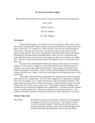
System Components<br />
The <strong>wireless</strong> <strong>local</strong> <strong>area</strong> <strong>network</strong> (WLAN) is made up of several different subsystems. A<br />
<strong>block</strong> <strong>diagram</strong> of the system is shown in Fig.1. The inputs to the system will be desktop<br />
computers, laptop computers, and embedded systems (fixed and mobile). Each client<br />
has a <strong>wireless</strong> <strong>network</strong> card that can communicate with an access point (AP). The AP<br />
manages WLAN traffic and physically connects the <strong>wireless</strong> system to the wired <strong>local</strong><br />
<strong>area</strong> <strong>network</strong> (LAN). The wired LAN will then send the requested information back to<br />
the access points, which will relay it to the appropriate client.<br />
Figure 1: Block Diagram of a Wireless LAN
Modes of Operation<br />
The system will have three modes of operation:<br />
Op-Mode: This is the standard operating mode for operation for system<br />
operation. The mode consists of interaction between clients and one or more<br />
server. The clients are <strong>wireless</strong> devices such as laptops, desktops and telerobtics.<br />
Servers are access points that connect the clients to a wired <strong>network</strong>. Quality of<br />
communication between the clients and server depends on distance, obstructions,<br />
RF noise level and number of <strong>network</strong> traffic.<br />
Manage Mode: This mode will be accessible to system administrators. It<br />
consists of software, which allows administrators to maintain and modify system<br />
settings. The software will most likely be located on the access point and<br />
accessed either by telnet or a web browser.<br />
Test Mode: This mode contains the diagnostic programming that examines the<br />
performance of the overall <strong>network</strong>, along with the separate components (i.e. the<br />
AP and <strong>network</strong> card). The test mode includes measurements such as signal<br />
quality, signal strength and <strong>network</strong> load as well as instructions on how to find<br />
and troubble shoot common problems.
There are five main subsystems in the system and three modes of operation. The<br />
subsystems are the client, manager, RF <strong>network</strong> card, access point and wired <strong>network</strong>.<br />
The modes of operation are op-mode, manage mode and test mode. Table 1 lists the<br />
different subsystems and how they operate under each control mode.<br />
Table 1: Subsystem Operations<br />
Subsystem<br />
Client<br />
Op-mode Manage Mode Test Mode<br />
Manager<br />
RF Network<br />
Card<br />
Access Point<br />
Wired<br />
Network<br />
The client computer will<br />
exchange data with its<br />
RF <strong>network</strong> card.<br />
The manager will be a<br />
client but will also<br />
monitor various<br />
functions such as RF<br />
<strong>network</strong> traffic.<br />
Exchanges data between<br />
client and the AP via<br />
802.11b DSSS format.<br />
Allows the RF LAN to<br />
access the wired LAN. It<br />
will receive data from<br />
the LAN and then relay<br />
it to the appropriate<br />
client radio through RF<br />
DSSS signals. It will also<br />
check for data from<br />
clients and relay it to the<br />
LAN.<br />
Allows the <strong>wireless</strong> LAN<br />
access to the Internet<br />
and the wired LAN.<br />
The system Client's computers will<br />
administrator may be be able to run a series of<br />
able to access a tests to diagnose <strong>network</strong><br />
configuration tool using problems and determine<br />
a web browser. The best placement and data<br />
client can also control rate of the client<br />
the <strong>local</strong> settings of its computers and APs.<br />
RF <strong>network</strong> card.<br />
The system The administrator will<br />
administrator can run be able to run a series of<br />
software on his/her tests to evaluate the<br />
computer to access a <strong>network</strong> and determine<br />
<strong>network</strong> configuration best placement and data<br />
tool that manages the RF rate of the client<br />
<strong>network</strong>.<br />
Exchanges data between<br />
client and the AP via<br />
802.11b DSSS format.<br />
Will contain <strong>network</strong><br />
management software<br />
that can be accessed by a<br />
system administrator<br />
from a web browser or<br />
commercial software.<br />
Allows the <strong>wireless</strong> LAN<br />
access to the Internet<br />
and the wired LAN.<br />
computers and APs.<br />
Exchanges data between<br />
client and the AP via<br />
802.11b DSSS format.<br />
Will be involved in many<br />
of the tests performed.<br />
Allows the <strong>wireless</strong> LAN<br />
access to the Internet<br />
and the wired LAN.
Specifications<br />
The specifications for the <strong>wireless</strong> LAN are based on the needs of the Bradley University<br />
ECE department. They are as follows:<br />
1) 20 -30 users<br />
2) Range of 100-150 feet in a closed environment.<br />
3) Throughput of at least 1-2Mbps<br />
4) Secure (40-128 bit encryption)<br />
The <strong>wireless</strong> LAN will need at least 1 AP and several <strong>network</strong> cards. The proposed AP is<br />
the Entrasys RoamAbout AP shown in Figure 2.<br />
Technical<br />
Frequency Band: 2400 - 2483.5 MHz<br />
Figure 2: RoamAbout AP by Entrasys<br />
Number of Selectable Sub Channels Subject to <strong>local</strong> regulations:<br />
(FCC):<br />
United States<br />
11<br />
France (FR): 4<br />
Japan (JP): 1<br />
Other Countries<br />
(ETSI):<br />
Modulation<br />
Technique:<br />
13<br />
Direct Sequence Spread Spectrum (CCK, DQPSK, DBPSK)<br />
Spreading: 11 -chip Barker sequence<br />
Bit Error Rate: Better than 10-5<br />
Media Access<br />
Protocol:<br />
CSMA/CA (Collision Avoidance) with ACK<br />
Interface: PC Card Type II Extended<br />
Data Rate: 11 Mbps (with fall back rates of 5.5, 2, and 1 Mbps) Automatic Rate Selection<br />
Range:<br />
Open Environment 66m @ 11 Mbps<br />
91m @ 5.5 Mbps<br />
125m @ 2 Mbps<br />
171m @ 1 Mbps
Semi-open<br />
Environment<br />
28m @ 11 Mbps<br />
35m @ 5.5 Mbps<br />
43m @ 2 Mbps<br />
53m @ 1 Mbps<br />
Receiver Sensitivity -84dBm @ 11 Mbps<br />
-87dBm @ 5.5 Mbps<br />
-90dBm @ 2 Mbps<br />
-93dBm @ 2 Mbps<br />
Compatibility: Supports Windows 95, 98, Windows NT (NDIS Miniport Driver), Windows 2000,<br />
Macintosh and Windows CE. Novell Client 3.x & 4.x<br />
The team recommends purchasing four Wireless <strong>network</strong> cards. One of these cards will<br />
be for the telerobotics group. The other three will be for testing. Two cards will be from<br />
Lucent one of which will be for the telerobotics group. One will be from Entrasys and<br />
one will be from 3Com.<br />
Timeline for spring semester '00<br />
•Weeks 1&2: Design of our system. (setup not permanent)<br />
•Week 3: Installation of the system.<br />
•Week 4: Getting familiar with the operation of the system.<br />
•Weeks 5 to 14: Develop modes of operation, design tests and troubleshoot the<br />
system.<br />
References
Network Computing (www.<strong>network</strong>computing.com)<br />
Angel, Jonathan. "Look Ma, No Cables,"<br />
Network Magazine (issue not known) : 42-52.<br />
802.11b standard