Reactive Power Compensation for Wind Power Plants - University of ...
Reactive Power Compensation for Wind Power Plants - University of ...
Reactive Power Compensation for Wind Power Plants - University of ...

Create successful ePaper yourself
Turn your PDF publications into a flip-book with our unique Google optimized e-Paper software.
Abstract—This technical paper provides the basic guidelines<br />
<strong>for</strong> the application <strong>of</strong> reactive compensation systems to be used as<br />
part <strong>of</strong> a wind power plant. A brief history <strong>of</strong> wind plant reactive<br />
compensation system is discussed, then the fundamental needs <strong>of</strong><br />
why reactive compensation is required. The paper will then<br />
provide some alternatives <strong>for</strong> reactive compensation, how to size<br />
the reactive compensation, and finally some <strong>of</strong> the principles on<br />
how different compensation devices work.<br />
Index Terms— voltage ride-through, induction generator,<br />
reactive power, wind power generation<br />
T<br />
<strong>Reactive</strong> <strong>Power</strong> <strong>Compensation</strong> <strong>for</strong> <strong>Wind</strong> <strong>Power</strong><br />
<strong>Plants</strong><br />
IEEE PES <strong>Wind</strong> Plant Collector System Design Working Group<br />
Contributing Members: E.H. Camm, M. R. Behnke, O. Bolado, M. Bollen, M. Bradt, C. Brooks, W. Dilling,<br />
M. Edds, W. J. Hejdak, D. Houseman, S. Klein, F. Li, J. Li, P. Maibach, T. Nicolai, J. Patiño, S. V. Pasupulati,<br />
N. Samaan, S. Saylors, T. Siebert, T. Smith, M. Starke, R. Walling<br />
I. INTRODUCTION<br />
he application <strong>of</strong> wind plants has grown dramatically in<br />
the recent past. Historically wind power plants (WPPs)<br />
have been smaller in size (less megawatts) per plant. The<br />
amount <strong>of</strong> wind penetration was not an issue <strong>for</strong> almost all<br />
applications. With the continued growth/increase in the<br />
individual turbine size and the number <strong>of</strong> turbines connected<br />
to the grid at a single connection point, wind plants can easily<br />
be in the hundreds <strong>of</strong> megawatts. The traditional turbine was<br />
usually a simple induction generator with little capability <strong>for</strong><br />
voltage ride through (VRT) or power factor (PF) control.<br />
During systems disturbances the plant would most likely trip<br />
<strong>of</strong>f-line. In addition, the wind plant did not have to supply any<br />
ancillary services such as voltage control, variable power<br />
factor, dynamic system support, etc. In general, older wind<br />
plants did not require reactive compensation systems. The<br />
recent generation <strong>of</strong> turbines has far greater capability. <strong>Wind</strong><br />
power plant centralized control systems can provide the<br />
ancillary services required by the interconnection agreements.<br />
In addition, more requirements are being applied to have the<br />
wind plants respond like traditional synchronous machine<br />
generation plants during fault conditions, and to have dynamic<br />
response and control capability. All <strong>of</strong> these factors require<br />
the wind plant to have a collector system design that can<br />
accommodate these conditions.<br />
978-1-4244-4241-6/09/$25.00 ©2009 IEEE<br />
II. REACTIVE POWER COMPENSATION<br />
The requirements and type <strong>of</strong> reactive power compensation<br />
in conjunction with the collector system are key to having a<br />
compliant wind plant system.<br />
A. Requirements<br />
There are multiple areas <strong>for</strong> consideration when deciding<br />
on the reactive power compensation system within the WPP<br />
collector design. Most WPPs have an interconnection<br />
agreement that may define the parameters <strong>of</strong> what is required.<br />
In the United States the Large Generator Interconnection<br />
Agreement (LGIA) <strong>for</strong> WPPs rated 20 MW or more defines<br />
the requirements associated with reactive power<br />
compensation. These requirements could refer to certain<br />
standards issued by FERC/NERC, local ISO requirements<br />
such as ERCOT and WECC, or local utility requirements.<br />
Some requirements could be the result <strong>of</strong> a system impact<br />
study that may have been per<strong>for</strong>med. FERC Order 661-A [1]<br />
defines the minimum power factor and VRT requirements <strong>for</strong><br />
the interconnection <strong>of</strong> WPPs to transmission providers under<br />
FERC jurisdiction. A wind power plant designer should be<br />
aware that a reactive power compensator alone may not<br />
ensure low voltage ride- through <strong>for</strong> the wind power plant.<br />
Rather, it is the interaction with the grid <strong>of</strong> the reactive power<br />
compensator with the particular wind turbine generators in the<br />
WPP as a system that influences compliance with these<br />
requirements.<br />
Once the main requirements are known there is a<br />
secondary listing that may further define items such as the<br />
response time, voltage control requirements, power factor<br />
control requirements, constant susceptance requirements, low<br />
voltage ride-through, high voltage ride-through, post fault<br />
contingency requirements, and voltage recovery requirements<br />
as part <strong>of</strong> the wind power plant and reactive compensation<br />
system.<br />
1) <strong>Power</strong> Factor Requirement<br />
FERC Order 661-A requires WPP to operate at power<br />
factors from 0.95 leading through 0.95 lagging if the<br />
Transmission Provider’s System Impact Study shows that<br />
such a requirement is necessary to insure operational security<br />
Authorized licensed use limited to: UNIVERSITY OF TENNESSEE. Downloaded on October 28, 2009 at 11:32 from IEEE Xplore. Restrictions apply.<br />
1
<strong>of</strong> the system. It is typically stated that the power factor (PF)<br />
compliance <strong>of</strong> the WPP must be met at the POI (Point <strong>of</strong><br />
Interconnection). The WPP is allowed to meet power factor<br />
requirement through the capabilities <strong>of</strong> the WTG (<strong>Wind</strong><br />
Turbine Generator), fixed and switched shunt<br />
capacitors/reactors or a combination <strong>of</strong> the two. The WPP is<br />
usually required to follow the voltage schedule (static voltage)<br />
imposed by the Transmission Provider which consequently<br />
determines the WPP operating PF required at any given time.<br />
It is recognized that the WPP may not be able to meet the<br />
power factor range requirement under all possible operating<br />
scenarios. For instance, when there is near zero power<br />
generation and only a couple <strong>of</strong> turbines may be online at low<br />
power levels, some transmission providers and grid codes<br />
allow a lower amount <strong>of</strong> power factor control [9].<br />
2) Dynamic Voltage Support Requirements<br />
FERC Order 661-A states that WPPs shall be able to<br />
provide sufficient dynamic voltage support (as opposed to<br />
static) in lieu <strong>of</strong> power system stabilizer and automatic<br />
voltage regulation <strong>of</strong> conventional generating units. Such<br />
requirements are imposed only if the Transmission Provider's<br />
System Impact Study concludes that the dynamic capability <strong>of</strong><br />
the WPP is necessary <strong>for</strong> operational security <strong>of</strong> the system.<br />
Some ISOs/RTOs further define the response time <strong>for</strong><br />
reactive support.<br />
3) Low Voltage Ride-Through Requirements<br />
WPPs are required to demonstrate low voltage ridethrough<br />
capability to interconnect to the transmission system.<br />
FERC Order 661-A states that the WPPs are required to<br />
remain in-service during three-phase faults with clearing time<br />
between 4 to 9 cycles. In other words, the WTGs should not<br />
trip <strong>for</strong> zero voltage at the high voltage side <strong>of</strong> the WPP<br />
substation trans<strong>for</strong>mer lasting up to 0.15 seconds. The WPP<br />
should also remain in-service during single-line-to-ground<br />
faults with delayed clearing, and subsequent post-fault voltage<br />
recovery to pre-fault voltage. The LVRT requirements do not<br />
apply <strong>for</strong> faults between the WTG terminals and the high<br />
voltage side <strong>of</strong> the WPP. The WPP may meet the LVRT<br />
requirements <strong>of</strong> this standard by the per<strong>for</strong>mance <strong>of</strong> the<br />
generators or by installing additional equipment or both<br />
The LVRT requirements in the FERC order represents the<br />
minimum requirements. Some ISOs/RTOs have adopted these<br />
requirements, and others such as WECC have proposed<br />
additional requirements. The WECC has a proposal [2] that is<br />
currently out <strong>for</strong> comment and balloting which applies to all<br />
generating units, including WTGs. In this proposal, beside the<br />
previously mentioned LVRT requirements, the generator's<br />
protection system is required not to trip the generator <strong>for</strong> the<br />
low voltage deviations <strong>of</strong> 20% <strong>for</strong> 40 cycles (post-disturbance<br />
undervoltage) at the high voltage side <strong>of</strong> the WPP substation<br />
trans<strong>for</strong>mer. It is also required that the owner <strong>of</strong> the WPP<br />
have evidence that their protection systems <strong>for</strong> WTG do not<br />
trip the generator during three-phase faults with normal<br />
clearing (<strong>for</strong> a maximum <strong>of</strong> 9 cycles).<br />
4) High Voltage Ride-Through Requirements<br />
WPPs are subject to high voltages that can occur in the<br />
transmission system following fault clearance, loss <strong>of</strong> large<br />
loads, or other system transients. There is no HVRT<br />
requirement in FERC Order 661-A. Some ISO/RTOs, NERC,<br />
and Hydro Quebec are in the process <strong>of</strong> implementing or have<br />
implemented such requirements. In many European countries<br />
WPPs are required not to trip <strong>for</strong> a high voltage level up to<br />
110% <strong>of</strong> the nominal voltage at the POI. WPPs are also<br />
required not to trip <strong>for</strong> higher voltage level if it lasts less than<br />
a pre-specified time period.<br />
B. <strong>Wind</strong> Plant Details<br />
With the requirements known the actual design and sizing<br />
<strong>of</strong> the reactive compensation can begin. The details <strong>of</strong> the<br />
wind plant will need to include the following items:<br />
• Point <strong>of</strong> interconnection (POI).<br />
• Minimum and maximum short-circuit levels with<br />
associated X/R ratios at the POI.<br />
• Make, model, MW rating and number <strong>of</strong> wind turbine<br />
generators (WTGs).<br />
• Control mode(s) at the POI; (i.e. voltage control,<br />
power factor control, constant susceptance control)<br />
along with the acceptable tolerances, dead bands,<br />
slopes, or other measures <strong>of</strong> dynamic response <strong>for</strong><br />
these items.<br />
• Location <strong>of</strong> turbines relative to the POI.<br />
• WTG power factor capability, control modes available<br />
(i.e., power factor, voltage, or reactive power).<br />
• WTG and wind power plant SCADA dynamic<br />
response times, WTG VRT capability.<br />
• WTG step-up trans<strong>for</strong>mer details (MVA, percent<br />
impedance, X/R ratio, and available taps).<br />
• Collector cable schedules, including cable types, sizes,<br />
and lengths.<br />
• If applicable, details <strong>of</strong> collector substation<br />
•<br />
trans<strong>for</strong>mer(s) (MVA, percent impedance, X/R ratio,<br />
and available taps)<br />
If applicable, transmission line data (R, L, C) and<br />
distance from the collector substation trans<strong>for</strong>mer to<br />
the POI.<br />
C. <strong>Wind</strong> Plant Analysis<br />
As mentioned previously, a system impact study may have<br />
been completed already to provide the requirements <strong>of</strong> the<br />
reactive power compensation system <strong>for</strong> the wind power<br />
plant. It will be necessary to per<strong>for</strong>m more detailed studies to<br />
further define the actual components <strong>of</strong> the reactive power<br />
compensation system. Some <strong>of</strong> the standard studies that are<br />
done in conjunction with the reactive compensation system<br />
are steady-state load flow, dynamic (or voltage stability), and<br />
harmonic analyses.<br />
The studies will incorporate the wind plant requirements<br />
and the actual details <strong>of</strong> the wind plant. The type <strong>of</strong> reactive<br />
compensation could be from any combination <strong>of</strong> the WTGs,<br />
mechanically-switched devices (i.e., shunt capacitor or reactor<br />
banks), STATCOMS, SVCs, etc. The actual devices chosen<br />
Authorized licensed use limited to: UNIVERSITY OF TENNESSEE. Downloaded on October 28, 2009 at 11:32 from IEEE Xplore. Restrictions apply.<br />
2
will have to comply with the requirements <strong>of</strong> the wind plant.<br />
Further items <strong>for</strong> consideration may include voltage<br />
limitations during switching <strong>of</strong> shunt capacitors, power quality<br />
requirements such as flicker during start up or cut-in,<br />
harmonics, etc.<br />
Studies which involve the reactive power compensation<br />
system are discussed next. Other wind power plant studies<br />
are discussed in a companion Working Group paper.<br />
1) Load Flow Studies<br />
Load flow studies typically require a detailed model <strong>of</strong> the<br />
collector grid with the actual cables and routing taken into<br />
account. The POI should be clearly defined and in accordance<br />
with the interconnection requirements. This may be on the<br />
high side or low side <strong>of</strong> the main substation trans<strong>for</strong>mer, or<br />
even located miles away if an additional transmission line was<br />
added <strong>for</strong> the wind power plant.<br />
Some wind power plants have on-load tap changers<br />
(OLTCs) on the main substation trans<strong>for</strong>mer. The turbine PF<br />
range capability shall be taken into account. Note some<br />
turbines have the ability to vary power factor while others<br />
maintain a constant power factor. The reactive compensation<br />
needs to be modeled also. The types <strong>of</strong> reactive compensation<br />
are discussed in section III.B.<br />
Typically the power factor range is required at nominal<br />
voltage, but it may also be required if the POI voltage is<br />
varied (i.e. +/-5%) while maintaining required power factor<br />
range. The reactive compensation system usually is required<br />
to be operational between +/-10% voltage at the POI, but the<br />
available range may have a reduced range during this<br />
condition. The power factor requirement may also change as a<br />
function <strong>of</strong> the generation level [9]. The WPP does have<br />
auxiliary load that should be included in the analysis.<br />
2) Dynamic Analysis<br />
Dynamic analysis is per<strong>for</strong>med to varying degrees between<br />
projects. This analysis may be provided by the transmission<br />
provider/ISO or by the WPP. If the interconnecting utility can<br />
supply the actual phasor (or rms) model with the base cases<br />
and contingencies this will yield the best results. Some<br />
utilities do not provide their system details, thus it may be<br />
required to build an equivalent utility system model (less<br />
preferred) from the known data. In addition to this model<br />
provided by the interconnecting utility or equivalent system,<br />
models <strong>of</strong> all other devices should be added as mentioned<br />
above <strong>for</strong> the load flow. The turbine dynamic model with<br />
actual settings is important. Refer to section IV on voltage<br />
ride-through <strong>for</strong> more detail.<br />
Dynamic analysis has a base requirement per FERC Order<br />
661-A. This requires zero voltage ride through <strong>for</strong> 3-phase<br />
faults on the high side <strong>of</strong> the main power trans<strong>for</strong>mer cleared<br />
in 4-9 cycles (depending on the fault clearing times <strong>of</strong> the<br />
circuit breakers involved and further definition provided by<br />
the local transmission provider) and single line-ground faults<br />
with delayed clearing. Typically single line-ground fault<br />
clearing times are provided by the transmission provider.<br />
The studies may also include the response time <strong>of</strong> the<br />
complete system to meet the reactive power requirements.<br />
Some ISO’s require that the WPP responds similarly to that <strong>of</strong><br />
conventional synchronous generators and that power factor<br />
targets are met within a short duration (i.e. 1 second). This<br />
may be equivalent to traditional excitation systems on<br />
generators.<br />
3) Harmonic and Flicker Analysis<br />
Harmonic analysis will require the same inputs as used <strong>for</strong><br />
the load flow studies with the addition <strong>of</strong> a few items. Any<br />
harmonics generation sources within the wind farm shall be<br />
included. This typically includes the WTGs and, if applicable,<br />
the reactive compensation devices. All types <strong>of</strong> turbines can<br />
create resonance conditions, due to passive elements in their<br />
design. In addition Type 3 and 4 [10] WTGs can create<br />
resonance due to their control design. The short-circuit level<br />
range at the POI with associated X/R ratios will also be<br />
needed. Care should be taken to insure frequency dependent<br />
elements are modeled correctly. It is also sometimes required<br />
to include any background/existing “ambient” harmonics and<br />
local reactive compensation devices. Typically the<br />
background harmonics are not known at the time <strong>of</strong> the<br />
studies, but may be required if analysis reveals resonance<br />
conditions at characteristic harmonic frequencies.<br />
The harmonic analysis should cover all reasonable<br />
operating scenarios. Different combinations <strong>of</strong> generation<br />
output, components <strong>of</strong> the reactive compensation, shortcircuit<br />
levels, etc will need to be modeled. Resonance<br />
conditions can occur due to substation switched capacitor<br />
banks and power factor correction capacitors (PFCCs) in<br />
WTGs. Detuning <strong>of</strong> the capacitor banks may be required in<br />
some cases, to ensure potential impacts do not negatively<br />
affect the collector system and equipment. It may not be<br />
possible to avoid all resonance conditions, but it should be<br />
avoided in the most common operating scenarios.<br />
The harmonic generation level requirements may be<br />
defined in the generation interconnection details. In the<br />
United States IEEE Std. 519 [11] is commonly used as a<br />
guideline <strong>for</strong> these requirements.<br />
<strong>Power</strong> quality <strong>of</strong> the WPP may be limited to the harmonic<br />
analysis, but may also include flicker calculations. The main<br />
concern <strong>for</strong> flicker is the voltage change that may occur when<br />
a SSD is switched or during WTG startup and cut-in. Large<br />
steps in voltage, 1% to 5% depending upon the turbine<br />
manufacturer, may have an adverse effect on the WTG, in<br />
particular the gear box. Other flicker concerns due to<br />
continuous or switching operations (such as startup and cutin)<br />
are usually limited to small wind power plants connected<br />
to distribution systems that other customers may be directly<br />
connected to. To analyze this detail <strong>of</strong> flicker the turbine<br />
manufacturer needs to provide the associated flicker test data<br />
<strong>of</strong> their units.<br />
III. REACTIVE POWER FLOW DURING NORMAL OPERATION<br />
The reactive power flow from the grid to the wind plant at<br />
the POI is given, simplified, by the following expression:<br />
Q = Q + I X −V<br />
ωC<br />
− Q<br />
2<br />
2<br />
3 (1)<br />
Authorized licensed use limited to: UNIVERSITY OF TENNESSEE. Downloaded on October 28, 2009 at 11:32 from IEEE Xplore. Restrictions apply.<br />
poi<br />
gen<br />
comp<br />
3
where Qgen is the leading (inductive) reactive power<br />
consumption <strong>of</strong> the turbines (which is negative when WTG is<br />
operating at a lagging (capacitive) power factor), X the<br />
equivalent series reactance <strong>of</strong> cables, lines and trans<strong>for</strong>mers,<br />
C the equivalent shunt reactance <strong>of</strong> (especially) cables, and<br />
Qcomp the reactive-power injected by any centralized reactive<br />
power compensation system. For simple induction generators<br />
the reactive power consumption depends on the loading and<br />
on the terminal voltage according to the following<br />
approximation:<br />
2<br />
V 2<br />
Qgen<br />
= + 3I<br />
X l<br />
(2)<br />
X<br />
m<br />
Where Xm and Xl are the magnetizing and leakage<br />
reactance, respectively. For DFIG and full-power-converter<br />
machines the reactive power can be controlled on the<br />
terminals <strong>of</strong> the machine or at the grid side <strong>of</strong> the turbine<br />
trans<strong>for</strong>mer within the WTG capability.<br />
Without any reactive power compensation, the reactivepower<br />
exchange consists <strong>of</strong> a term proportional to the square<br />
<strong>of</strong> the voltage and a term proportional to the square <strong>of</strong> the<br />
current. As the voltage variations are much less than the<br />
current variations, it is the latter term that requires the main<br />
compensation.<br />
A. Example<br />
The generation and consumption range <strong>of</strong> reactive power<br />
<strong>for</strong> 200 MW WPP is summarized in Table I. The WPP<br />
consists <strong>of</strong> 100 2-MW Type 3 WTG with PF capabilities from<br />
0.98 leading to 0.98 lagging. A total <strong>of</strong> 72 MVAR (6 steps, 12<br />
MVAR each) <strong>of</strong> reactive power compensation is installed on<br />
the substation MV bus. The reactive power generated by the<br />
cables is given <strong>for</strong> rated voltage. The variations in collector<br />
cable reactive-power generation are small during normal<br />
operation. The reactive power consumed by the series<br />
reactance <strong>of</strong> the cables and trans<strong>for</strong>mers is given <strong>for</strong> rated<br />
current. The reactive-power consumption varies with the<br />
square <strong>of</strong> the current. It is this variation that requires<br />
compensation to meet the requirements at the POI.<br />
TABLE I<br />
REACTIVE POWER FLOWS FOR A CERTAIN OPERATING SCENARIO IN A 200 MW<br />
Elements <strong>of</strong> WPP<br />
WPP<br />
<strong>Reactive</strong> power<br />
generated at rated<br />
voltage<br />
Substation trans<strong>for</strong>mer (235<br />
MVA, 345/34.5 kV)<br />
Substation<br />
compensation<br />
based reactive<br />
<strong>Reactive</strong> power<br />
consumed at rated<br />
current<br />
------ 38 Mvar<br />
0 to 72 Mvar ------<br />
Collector 38 kV cables/OH lines 11 Mvar 7 Mvar<br />
WTG Trans<strong>for</strong>mers ------ 23 Mvar<br />
WTGs (Type 3, PF range from<br />
0.98 leading to 0.98 lagging)<br />
0 to 40 Mvar 0 to 40 Mvar<br />
Total 11 to 123 Mvar 68 to 108 Mvar<br />
B. Types <strong>of</strong> <strong>Reactive</strong> <strong>Power</strong> <strong>Compensation</strong><br />
The following is a listing <strong>of</strong> the main types <strong>of</strong> reactive<br />
power compensation equipment and some general principles<br />
<strong>of</strong> operation.<br />
1) Mechanically-Switched Shunt Capacitors<br />
Capacitors banks typically consist <strong>of</strong> a grouping <strong>of</strong><br />
individual capacitor units. The bank is then either considered<br />
fixed or it can be switched using appropriately rated devices.<br />
These banks can either be “metal enclosed” or “open rack”<br />
design. It is important that special attention be paid to the<br />
switches. They should be rated <strong>for</strong> capacitor switching [4]. It<br />
is only possible to control slow variations in reactive power.<br />
The capacitive VAr output is a function <strong>of</strong> the voltage such<br />
that the VArs decrease with the square <strong>of</strong> the voltage (i.e.<br />
90% voltage will provide 81% VAr capability) Using a<br />
number <strong>of</strong> capacitor banks <strong>of</strong> different size, the reactive<br />
power exchange can be kept within a range. Capacitor banks<br />
typically require a 5 minute discharge time be<strong>for</strong>e they can be<br />
re-energized, but there are also designs that allow <strong>for</strong> shorter<br />
durations on a limited basis.<br />
2) Mechanically-Switched Shunt and Regulated Reactors<br />
Reactors are typically mechanically switched devices.<br />
Again, it is only possible to control slow variations in reactive<br />
power. The inductive VAr output is a function <strong>of</strong> the voltage<br />
such that the VArs decrease with the square <strong>of</strong> the voltage<br />
(i.e. 90% voltage will provide 81% VAr capability).<br />
Regulated shunt reactors are shunt reactors equipped with<br />
a tap-changer as used <strong>for</strong> voltage control with a trans<strong>for</strong>mer.<br />
Using such a ”regulated shunt-reactor”, a more smooth<br />
control <strong>of</strong> reactive power can be achieved [6]. A study<br />
presented in [5] shows the feasibility <strong>of</strong> this tool <strong>for</strong> reactive<br />
power control with large wind power plants.<br />
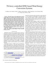
3) Static Var Compensator<br />
An SVC is typically a fixed shunt capacitance in parallel<br />
with reactance that is controlled using thyristors. This type <strong>of</strong><br />
controller is made using static components. When the<br />
thyristors are used in the control process, then the controller is<br />
considered dynamic. These allow <strong>for</strong> a control <strong>of</strong> reactive<br />
power at time scales down to the order <strong>of</strong> a 100 milliseconds.<br />
Additional filters must be used to avoid harmonics which are<br />
created when the current wave shape distorts from the<br />
thyristor switching. Further details on SVC can be found in<br />
IEEE Std.1031.<br />
Medium Voltage<br />
Transmission Voltage<br />
POI<br />
Collector Feeder Circuit SVC<br />
Figure 1. Typical configuration <strong>of</strong> SVC <strong>for</strong> WPPs.<br />
Authorized licensed use limited to: UNIVERSITY OF TENNESSEE. Downloaded on October 28, 2009 at 11:32 from IEEE Xplore. Restrictions apply.<br />
4
4) Static Synchronous Compensator<br />
A STATCOM is a voltage-source converter. It does not<br />
use thyristors <strong>for</strong> switching, but instead uses IGBT (Insulated-<br />
Gate Bipolar Transistor) or IGCT (Integrated Gate<br />
Commutated Thyristor) switching devices to either source or<br />
sink reactive power to the electric network. Some STATCOM<br />
units may have short-time overload capabilities <strong>for</strong> 2 to 4<br />
seconds. The VAr output is a linear function <strong>of</strong> the voltage,<br />
VArs decrease linearly with the voltage (i.e. 90% voltage will<br />
provide 90% VAr capability) since they are constant current<br />
controllers.<br />
Medium Voltage<br />
Transmission Voltage<br />
Figure 2. Typical configuration <strong>of</strong> STATCOM <strong>for</strong> WPPs.<br />
5) WTGs<br />
WTGs can provide or consume reactive power, depending<br />
on the type. Simple induction generators typically employ<br />
PFCCs to correct the power factor at the terminals <strong>of</strong> the<br />
machine to unity <strong>of</strong> near unity. DFIG and full converter-based<br />
WTGs can operate dynamically over a defined power factor<br />
range (e.g. 0.95 inductive to 0.95 capacitive). A specific<br />
turbine may have different steady state vs. dynamic capability.<br />
Refer to a companion WG paper <strong>for</strong> more details on WTG<br />
reactive power capabilities.<br />
C. Choice <strong>of</strong> reactive power compensation<br />
The reactive power compensation <strong>for</strong> a wind plant typically<br />
consists <strong>of</strong> a combination <strong>of</strong> different technologies. Assume<br />
that the reactive power required to be generated by the wind<br />
power plant, is between inductive 50 Mvar to capacitive 100<br />
Mvar. Some <strong>of</strong> the possible solutions could be:<br />
Qty 2 – 25 Mvar switched shunt reactors and Qty 4-<br />
25 Mvar switched shunt capacitors. This solution will<br />
not be able to hit a specific power factor or voltage<br />
target under all conditions.<br />
Qty 4 – 12.5 Mvar switched shunt reactors and Qty 8-<br />
12.5 Mvar switched shunt capacitors. This solution will<br />
be able to hit more specific power factor or voltage<br />
targets, but still not all under all conditions.<br />
Qty 1 – 25 Mvar switched shunt reactor, Qty 1- 25<br />
Mvar regulated reactor and Qty 4 – 25 Mvar switched<br />
shunt capacitors. This solution should be able to come<br />
close to a specific power factor or voltage target under<br />
all conditions.<br />
Qty 2 – 25 Mvar switched shunt capacitors and +/-50<br />
POI<br />
Collector Feeder Circuit ~<br />
STATCOM =<br />
MVAR from WTG’s, assuming WTG’s have the<br />
capability. This solution should be able to hit a specific<br />
power factor or voltage target under all conditions.<br />
Qty 1 – -50 to +100 Mvar SVC. This solution will be<br />
able to hit a specific power factor or voltage target<br />
under all conditions.<br />
Qty 1 – -50 to +100 Mvar STATCOM. This solution<br />
will be able to hit a specific power factor or voltage<br />
target under all conditions.<br />
The choice <strong>of</strong> reactive power compensation system is an<br />
economic decision considering initial investment and lifecycle<br />
cost, where the requirements set by the network<br />
operator act as an important boundary condition.<br />
IV. VOLTAGE RIDE-THROUGH<br />
Transmission system operators <strong>of</strong>ten put strict<br />
requirements on the voltage ride-through <strong>of</strong> wind power<br />
plants. The details <strong>of</strong> the requirements differ between network<br />
operators and this paper does not aim at covering all possible<br />
requirements. There are however some common elements in<br />
most <strong>of</strong> the requirements on voltage ride-through.<br />
• A worst-case voltage dip is defined <strong>for</strong> which the wind<br />
power plant should remain connected to the grid. In<br />
many cases a fault at the POI is assumed with a given<br />
duration. After the fault a slow voltage recovery is<br />
assumed.<br />
• The wind power plant production should recover to its<br />
pre-fault value within a certain time after fault clearing.<br />
• Some network operators also put requirements on<br />
active and/or reactive power flows during the fault.<br />
Not all network operators have such requirements in place,<br />
but it is to be expected that with the growing penetration <strong>of</strong><br />
wind power, soon all transmission network operators will<br />
en<strong>for</strong>ce rather strict requirements on voltage ride-through.<br />
A. Design requirements<br />
Different solutions <strong>for</strong> voltage ride-through have been<br />
developed and are under development by different wind<br />
turbine manufacturers. Voltage ride-through may be obtained<br />
by making the turbine immune against the worst-case voltage<br />
dips or in combination with certain measures in the collection<br />
grid. It is possible that the WTG does have VRT capability<br />
and still fails to comply with the interconnect VRT<br />
requirements.<br />
In this section we will discuss some <strong>of</strong> the aspects <strong>of</strong><br />
voltage-ride-through, without being able to go into details.<br />
The requirements on voltage-ride-through also have their<br />
consequences on the protection and coordination <strong>of</strong> the<br />
WTGs.<br />
1) During-fault behavior<br />
A fault at the POI will put severe restrictions on the<br />
amount <strong>of</strong> active power that can be produced by the turbines.<br />
Consider a simple model with one aggregated turbine<br />
connected to the POI through an impedance Z = R + jX. For a<br />
three-phase fault at the POI, the active and reactive power<br />
flows from the turbines towards the grid are:<br />
Authorized licensed use limited to: UNIVERSITY OF TENNESSEE. Downloaded on October 28, 2009 at 11:32 from IEEE Xplore. Restrictions apply.<br />
5
2<br />
V<br />
P = R (3)<br />
2<br />
Z<br />
2<br />
V<br />
Q = X (4)<br />
2<br />
Z<br />
where V is the terminal voltage <strong>of</strong> the turbines. Note that<br />
the power flowing into the grid is zero since the voltage at the<br />
POI is zero. This may result in the turbines accelerating and in<br />
power electronic converters either tripping or reaching their<br />
current limit. It is important to ensure that no dangerous<br />
overspeed is reached and that the converters remain<br />
connected or are reconnected quickly once the voltage has<br />
recovered<br />
2) Post-fault recovery<br />
The behavior after the fault depends strongly on the type <strong>of</strong><br />
machine. With type 1 and 2 WTG’s, sufficient reactive power<br />
should be available to bring the machines back to their<br />
nominal speed. A design rule, <strong>for</strong> industrial systems with large<br />
amounts <strong>of</strong> induction machines, is that the grid should be able<br />
to supply six times the rated power <strong>of</strong> the machines as<br />
reactive power, without the voltage at the machine terminals<br />
dropping below 0.7 pu. Additional sources <strong>of</strong> reactive power<br />
may be needed <strong>for</strong> this in wind power plants due to the large<br />
distances between the individual turbines. Sometimes a<br />
collector based solution (not within the turbine) is used.<br />
An additional problem with DFIG machines is that the<br />
controller should be able to detect the transition from fault to<br />
post-fault. The response is dependent on the pre-fault<br />
operating state <strong>of</strong> the WTG (e.g., supersynchronous vs.<br />
subsynchronous speed), the nature <strong>of</strong> the fault (balanced or<br />
unbalanced), and the specific measures taken by the WTG<br />
manufacturer to limit the converter DC link voltage during<br />
these events. If the WTG does not crowbar during VRT it<br />
typically can supply reactive power during this time, if it does<br />
crowbar it will consume reactive power similar to a Type 1<br />
WTG. The voltage at the turbine terminals needs to have<br />
recovered sufficiently <strong>for</strong> the DFIG controller to be able to<br />
switch back to normal operation. This may require some<br />
central source <strong>of</strong> reactive power as well. The details <strong>of</strong> this<br />
depend on the design <strong>of</strong> the turbine and its controller.<br />
The recovery <strong>of</strong> turbines with a full power converter is<br />
easier as they do not require any reactive power. Once the<br />
voltage at the POI recovers, the voltage at the terminals <strong>of</strong> the<br />
converters recovers and their controllers can switch back to<br />
normal operation.<br />
B. Example<br />
<strong>Wind</strong> plants have a certain voltage ride-through capability<br />
even without additional measures. This depends among others<br />
on the voltage-sag immunity <strong>of</strong> the turbines. As mentioned<br />
be<strong>for</strong>e, <strong>for</strong> induction generators the source impedance at the<br />
generator terminals is an important factor as well. The<br />
voltage-ride-through <strong>of</strong> such a wind power plant is shown in<br />
Fig. 3 <strong>for</strong> two values <strong>of</strong> the short-circuit ratio (SCR) [7]. The<br />
requirements set by the network operator are typically more<br />
stringent than this so that additional measures are needed.<br />
Fig. 3. Voltage ride-through <strong>of</strong> a wind power plant with induction machines<br />
without any additional ride-through measures as a function <strong>of</strong> the short circuit<br />
ratio.<br />
C. Simulations<br />
Once a preliminary design <strong>for</strong> the wind plant has been<br />
chosen, a dynamic simulation <strong>of</strong> the complete wind plant is<br />
needed to verify if it fulfills the requirements on voltage ridethrough.<br />
Such a simulation should contain a detailed model <strong>of</strong><br />
the turbines, including their control system, and <strong>of</strong> the<br />
complete collection grid. Any control equipment (like SVC or<br />
switched capacitor banks) present in the collection grid should<br />
also be included in the model.<br />
It is strongly recommended to use a time-domain model<br />
(also known as “electromagnetic transient model”) instead <strong>of</strong><br />
just a phasor model (also known as “rms model”).<br />
To fulfill the voltage ride-through requirements it is also<br />
needed to obtain in<strong>for</strong>mation from the turbine manufacturer<br />
about the behavior <strong>of</strong> the turbines during low voltage<br />
situations. In many cases it will be needed to obtain black-box<br />
models <strong>of</strong> the turbines and their control system.<br />
Various studies have shown that aggregated or simplified<br />
models may not give accurate results <strong>of</strong> the voltage ride<br />
through. Such models may still be used to illustrate the impact<br />
<strong>of</strong> different parameters and to study different improvement<br />
methods. However to illustrate the fault-ride-through <strong>of</strong> a real<br />
wind power plant against a real grid, a complete and detailed<br />
model is needed.<br />
V. REFERENCES<br />
[1] FERC Order No. 661-A, Interconnection <strong>for</strong> <strong>Wind</strong> Energy, Docket No.<br />
RM05-4-001, December 2005.<br />
[2] WECC PRC-024-WECC-1, Generator Low Voltage Ride-Through<br />
Criterion, Post Draft, September 2008.<br />
[3] Y. Lei, A. Mullane, and G. Lightbody, “Modeling <strong>of</strong> the wind turbine with<br />
a doubly fed induction generator <strong>for</strong> grid integration study,” IEEE Trans.<br />
Energy Conversion, vol. 21, pp. 257-264, Mar. 2006.<br />
[4] IEEE Standard <strong>for</strong> Requirements <strong>for</strong> Capacitor Switches <strong>for</strong> AC Systems<br />
(1 kV to 38 kV), IEEE Std. C37.66-2005.<br />
Authorized licensed use limited to: UNIVERSITY OF TENNESSEE. Downloaded on October 28, 2009 at 11:32 from IEEE Xplore. Restrictions apply.<br />
6
[5] M. Bollen, C. Bengtsson, L.H. Nielsen, P.H. Larsen, S.D. Mikkelsen,<br />
“Application <strong>of</strong> regulated shunt reactor <strong>for</strong> <strong>of</strong>f-shore wind farms,” in<br />
CIGRE Symposium, Brugge, Belgium, October 2007.<br />
[6] G. Bertagnolli, A. Babare, F. Iliceto, F.M. Gatta, “Design and application<br />
<strong>of</strong> variable Mvar output shunt reactors with on load tap-changer, Operation<br />
experience in Africa,” in CIGRE Sessions 1998, Paris, France, paper 12-<br />
308.<br />
[7] Cuong Le, results from the MSc project at Chalmers <strong>University</strong> <strong>of</strong><br />
Technology, report under preparation.<br />
[8] T. Petru, T. Thiringer, “Modeling <strong>of</strong> wind turbines <strong>for</strong> power system<br />
studies,” IEEE Trans. <strong>Power</strong> Systems, vol. 17, no. 4, pp. 1132-1139,<br />
November 2002.<br />
[9] The Grid Code, UK issued by National Grid Electricity Transmission plc,<br />
Electricity codes regulatory Frameworks.<br />
[10] <strong>Wind</strong> Plant Collector Design WG, “Characteristics <strong>of</strong> <strong>Wind</strong> Turbine<br />
Generators <strong>for</strong> <strong>Wind</strong> <strong>Power</strong> <strong>Plants</strong>,” in Proc. 2009 IEEE <strong>Power</strong> and<br />
Energy Society General Meeting, Calgary, Canada, July 2009.<br />
[11] IEEE Std. 519-1992, IEEE Recommended Practices and Requirements<br />
<strong>for</strong> Harmonic Control in Electric <strong>Power</strong> Systems.<br />
Authorized licensed use limited to: UNIVERSITY OF TENNESSEE. Downloaded on October 28, 2009 at 11:32 from IEEE Xplore. Restrictions apply.<br />
7