ieee transactions on power electronics, vol. 19, no. 3, may
ieee transactions on power electronics, vol. 19, no. 3, may
ieee transactions on power electronics, vol. 19, no. 3, may

You also want an ePaper? Increase the reach of your titles
YUMPU automatically turns print PDFs into web optimized ePapers that Google loves.
IEEE TRANSACTIONS ON POWER ELECTRONICS, VOL. <strong>19</strong>, NO. 3, MAY 2004 783<br />
Extending the C<strong>on</strong>stant Power Speed Range<br />
of the Brushless DC Motor Through<br />
Dual-Mode Inverter C<strong>on</strong>trol<br />
J. S. Lawler, Senior Member, IEEE, J. Milt<strong>on</strong> Bailey, John W. McKeever, and João Pinto<br />
Abstract—An inverter topology and c<strong>on</strong>trol scheme has been developed<br />
and tested to dem<strong>on</strong>strate that it can drive low-inductance,<br />
surface mounted permanent magnet motors over the wide c<strong>on</strong>stant<br />
<strong>power</strong> speed range (CPSR) required in electric vehicle applicati<strong>on</strong>s.<br />
This new c<strong>on</strong>troller, called the dual-mode inverter c<strong>on</strong>troller<br />
(DMIC) [1], can drive both the Permanent Magnet Synchr<strong>on</strong>ous<br />
Machine with sinusoidal back emf, and the brushless dc machine<br />
(BDCM) with trapezoidal emf as a motor or generator. Here we<br />
c<strong>on</strong>centrate <strong>on</strong> the applicati<strong>on</strong> of the DMIC to the operati<strong>on</strong> of<br />
the BDCM in the motoring mode. Simulati<strong>on</strong> results, supported<br />
by closed form analytical expressi<strong>on</strong>s, show that the CPSR of the<br />
DMIC driven BDCM is infinite when all of the motor and inverter<br />
loss mechanisms are neglected. The expressi<strong>on</strong>s further show that<br />
the ratio of high-to-low motor inductances accommodated by the<br />
DMIC is 11 making the DMIC compatible with both low- and highinductance<br />
BDCMs. Classical hysteresis-band motor current c<strong>on</strong>trol<br />
used below base speed is integrated with DMICs phase advance<br />
above base speed. The <strong>power</strong> performance of the DMIC is<br />
then simulated across the entire speed range. Laboratory testing<br />
of a low-inductance, 7.5-hp BDCM driven by the DMIC dem<strong>on</strong>strated<br />
a CPSR above 6:1. Current peak and rms values remained<br />
c<strong>on</strong>trolled below rated values at all speeds. A computer simulati<strong>on</strong><br />
accurately reproduced the results of lab testing showing that the<br />
limiting CPSR of the test motor is 8:1.<br />
Index Terms—Brushless dc machine (BDCM), c<strong>on</strong>stant <strong>power</strong><br />
speed range (CPSR), dual-mode inverter c<strong>on</strong>troller (DMIC).<br />
I. THEORY AND SIMULATION<br />
THE TRAPEZOIDAL back emf brushless dc motor<br />
(BDCM) with surface-mounted magnets has high <strong>power</strong><br />
density and efficiency especially when rare-earth magnet<br />
materials such as samarium-cobalt or neodymium-ir<strong>on</strong>-bor<strong>on</strong><br />
are used. Tracti<strong>on</strong> applicati<strong>on</strong>s, such as electric vehicles, could<br />
benefit significantly from the use of such motors. Transmissi<strong>on</strong>less<br />
electric passenger vehicles require a c<strong>on</strong>stant <strong>power</strong><br />
speed ratio (CPSR) of 4:1 or more. Larger electric vehicles,<br />
such as heavy trucks, tanks, and other heavy equipment, can<br />
require a CPSR of 10:1. Unfortunately, a practical means for<br />
Manuscript received August 16, 2002; revised September 1, 2003. This work<br />
was supported by the Oak Ridge Nati<strong>on</strong>al Laboratory, UT-Battelle, LLC, U.S.<br />
Department of Energy under C<strong>on</strong>tract DE-AC05-00OR22725. Recommended<br />
by Associate Editor L. Xu.<br />
J. S. Lawler is with the University of Tennessee, K<strong>no</strong>xville, TN 37932 USA.<br />
J. M. Bailey is with the Oak Ridge Nati<strong>on</strong>al Laboratory, Oak Ridge, TN 37932<br />
USA.<br />
J. W. McKeever is with the Oak Ridge Nati<strong>on</strong>al Laboratory, Oak Ridge,<br />
TN 37932 USA and also with the Nati<strong>on</strong>al Transportati<strong>on</strong> Research Center,<br />
K<strong>no</strong>xville, TN 37932 (e-mail: mckeeveryjw@ornl.gov).<br />
J. Pinto is with the Universidade Federal, de Matto Grosso do Sul, Brazil.<br />
Digital Object Identifier 10.1109/TPEL.2004.826511<br />
U.S. Government work <strong>no</strong>t protected by U.S. Copyright<br />
driving the BDCM over a CPSR of 4:1 to 6:1 has <strong>no</strong>t been<br />
dem<strong>on</strong>strated. A key feature of these motors is that they have<br />
low internal inductance. C<strong>on</strong>venti<strong>on</strong>al phase advance (CPA)<br />
methods [2]–[5] are effective in c<strong>on</strong>trolling the motor <strong>power</strong><br />
over such a speed range. However, the current at high speed<br />
<strong>may</strong> be several times greater than that required at the base<br />
speed. The increase in current during high-speed operati<strong>on</strong><br />
is caused by the low motor inductance and the acti<strong>on</strong> of the<br />
bypass diodes of the inverter [6], [7]. The use of CPA with<br />
a low-inductance motor requires an increased current rating<br />
of the inverter semic<strong>on</strong>ductors and additi<strong>on</strong>al cooling. Added<br />
cooling would be required for the inverter, where the losses<br />
increase proporti<strong>on</strong>ally with current, and for the motor, where<br />
the losses increase with the square of the current. As suggested<br />
for the sinusoidal emf motor [8], external series inductance can<br />
be added to mitigate the high-current problems associated with<br />
CPA. However, this reduces <strong>power</strong> density, could require an<br />
increase in supply <strong>vol</strong>tage, and leaves the CPSR performance<br />
of the system highly sensitive to variati<strong>on</strong>s in the available<br />
<strong>vol</strong>tage. A new inverter topology and c<strong>on</strong>trol scheme has been<br />
developed that can drive low-inductance BDCMs over the<br />
CPSR that would be required in electric vehicle applicati<strong>on</strong>s<br />
[1]. This new c<strong>on</strong>troller is called the dual-mode inverter c<strong>on</strong>trol<br />
(DMIC).<br />
The DMIC has the following features.<br />
1) Internal motor inductance can be low and is <strong>no</strong>t a critical<br />
parameter. Analytical results show that an inductance<br />
range of at least 11:1 can be tolerated.<br />
2) Independent of speed, the motor current can be c<strong>on</strong>trolled<br />
to remain within the rated rms value over the extended<br />
CPSR. Using the DMIC does <strong>no</strong>t increase motor-cooling<br />
requirements or increase the current-handling requirement<br />
of inverter-switching comp<strong>on</strong>ents.<br />
3) The DMIC works with either the Permanent Magnet Synchr<strong>on</strong>ous<br />
Machine (PMSM) with sinusoidal back emf [9]<br />
or the BDCM with trapezoidal back emf.<br />
4) Motoring and regenerati<strong>on</strong> can be c<strong>on</strong>trolled. For a<br />
low-inductance motor, it can be possible to regenerate at<br />
several times rated <strong>power</strong> for brief periods. This feature<br />
is attractive for applicati<strong>on</strong>s requiring rapid regenerative<br />
braking.<br />
5) For high-inductance motors, up to 50% more <strong>power</strong> can<br />
be developed during high-speed motoring operati<strong>on</strong> than<br />
can be developed at base speed at the same rms motor<br />
current. The exact amount of additi<strong>on</strong>al <strong>power</strong> depends<br />
<strong>on</strong> the inductance.
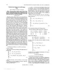
784 IEEE TRANSACTIONS ON POWER ELECTRONICS, VOL. <strong>19</strong>, NO. 3, MAY 2004<br />
Fig. 1. DMIC inverter topology and BDCM model.<br />
6) The c<strong>on</strong>troller provides the functi<strong>on</strong>al equivalent of field<br />
weakening without requiring an auxiliary field winding<br />
and its necessary c<strong>on</strong>trols or rotor saliency.<br />
CPA uses the comm<strong>on</strong> six-transistor, <strong>vol</strong>tage source inverter<br />
(VSI) topology. The DMIC supplements the comm<strong>on</strong> VSI with<br />
six thyristors, which, in additi<strong>on</strong> to enabling the performance<br />
enhancements, provide several important failure mode protecti<strong>on</strong><br />
features. These features are especially important in electric<br />
vehicle applicati<strong>on</strong>s and include the following.<br />
1) The DMIC inverter is capable of isolating the permanent<br />
magnet motor from short circuits that might develop in<br />
the dc supply system or in the inverter transistors.<br />
2) A c<strong>on</strong>troller board failure with the DMIC and attendant<br />
loss of semic<strong>on</strong>ductor firing signals results in rapid extincti<strong>on</strong><br />
of motor current so that the vehicle simply coasts.<br />
This same failure with CPA and the comm<strong>on</strong> VSI results<br />
in heavy regenerative braking.<br />
3) The DMIC inverter transistors can be rated for the dc<br />
supply <strong>vol</strong>tage. High-<strong>vol</strong>tage blocking, under <strong>no</strong>rmal or<br />
ab<strong>no</strong>rmal c<strong>on</strong>diti<strong>on</strong>s, is handled by the thyristors.<br />
II. THEORETICAL hIGH-SPEED DMIC PERFORMANCE<br />
In Secti<strong>on</strong> I we c<strong>on</strong>centrate <strong>on</strong> the high-speed performance<br />
of the DMIC in the motoring mode. Generating/braking operati<strong>on</strong><br />
for the BDCM is discussed in [6] while the applicati<strong>on</strong> of<br />
the DMIC to high speed operati<strong>on</strong> of the sinusoidal back emf<br />
machine can be found in [9].<br />
A. DMIC Inverter Topology and Semic<strong>on</strong>ductor Firing Scheme<br />
The DMIC inverter topology and permanent magnet motor<br />
model used in this work are shown in Fig. 1. The inverter c<strong>on</strong>sists<br />
of a comm<strong>on</strong> six transistor VSI bridge, each transistor<br />
having a parallel bypass diode. The bridge is interfaced to the<br />
motor through an ac <strong>vol</strong>tage c<strong>on</strong>troller, which c<strong>on</strong>sists of three<br />
pairs of antiparallel silic<strong>on</strong> c<strong>on</strong>trolled rectifiers (SCRs). A detailed<br />
discussi<strong>on</strong> of the operati<strong>on</strong> of the inverter can be found in<br />
[3], c<strong>on</strong>sequently, <strong>on</strong>ly a brief discussi<strong>on</strong> is given here.<br />
The purpose of the thyristors is to block undesired c<strong>on</strong>ducti<strong>on</strong><br />
of the bypass diodes during high-speed operati<strong>on</strong>. During<br />
high-speed motoring, the magnitude of the motor emf is sub-<br />
stantially larger than the value of dc supply <strong>vol</strong>tage. Since the<br />
bypass diodes form a diode rectifier between the high-<strong>vol</strong>tage<br />
source of the motor emf and the dc supply, there is a natural<br />
tendency toward regenerati<strong>on</strong> when the comm<strong>on</strong> VSI is used. In<br />
the DMIC inverter, motor current <strong>no</strong>rmally flows through the series<br />
combinati<strong>on</strong> of a transistor and a thyristor although during<br />
commutati<strong>on</strong> the current flow <strong>may</strong> be through a bypass diode<br />
and a thyristor. Since the thyristor will <strong>no</strong>t reverse c<strong>on</strong>duct, the<br />
current is shut off at the current zero crossing. In previous work<br />
[6], [7] it was shown that high-speed operati<strong>on</strong> is a mixture of<br />
motoring and regenerati<strong>on</strong> when phase advance is applied using<br />
the comm<strong>on</strong> VSI. For low-inductance motors, the current at high<br />
speed with CPA <strong>may</strong> be several times greater than the motor<br />
base speed rating and the mixture of motoring and regenerati<strong>on</strong><br />
is extreme. The regenerati<strong>on</strong> is associated with c<strong>on</strong>ducti<strong>on</strong><br />
of the bypass diodes, while the motoring comp<strong>on</strong>ent is associated<br />
with c<strong>on</strong>ducti<strong>on</strong> of the transistors. The braking comp<strong>on</strong>ent<br />
is large and cancels a like porti<strong>on</strong> of the motoring comp<strong>on</strong>ent,<br />
leaving a modest net motoring comp<strong>on</strong>ent. In the DMIC, the<br />
thyristors, which will <strong>no</strong>t reverse c<strong>on</strong>duct, eliminate the braking<br />
comp<strong>on</strong>ent that would otherwise result from bypass diode c<strong>on</strong>ducti<strong>on</strong>.<br />
The eliminati<strong>on</strong> of the braking comp<strong>on</strong>ent allows rated<br />
<strong>power</strong> to be developed at a greatly reduced current level. Despite<br />
the additi<strong>on</strong>al <strong>vol</strong>tage drops associated with the thyristors,<br />
the efficiency of the DMIC drive is superior to that of CPA when<br />
the motor inductance is low.<br />
In additi<strong>on</strong> to remaining within current rating during<br />
high-speed operati<strong>on</strong> at rated <strong>power</strong>, thyristor c<strong>on</strong>trol provides<br />
several fault tolerance benefits already menti<strong>on</strong>ed.<br />
The firing commands for the semic<strong>on</strong>ductors in phase a, transistors,<br />
Q1 and Q4, and thyristors, T1 and T4, are shown in<br />
Fig. 2. The firing commands for phases b and c are analogous<br />
to those for Fig. 2 but are delayed by <strong>on</strong>e-third and two-thirds<br />
of a cycle, respectively. Below base speed, the BDCM operates<br />
<strong>on</strong> two phases at a time in a “single phase” mode. Except for<br />
a short commutati<strong>on</strong> overlap period, the supply current flows<br />
into the motor through <strong>on</strong>e phase and returns through a sec<strong>on</strong>d<br />
phase, while the third phase idles. Because of the tendency of<br />
bypass diodes to c<strong>on</strong>duct at high speed, the single-phase mode<br />
of operati<strong>on</strong> is lost when CPA is used with the comm<strong>on</strong> VSI.<br />
In the CPA, the motor phase currents become c<strong>on</strong>tinuous and
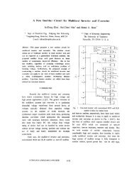
LAWLER et al.: EXTENDING THE CONSTANT POWER SPEED RANGE OF THE BRUSHLESS DC MOTOR 785<br />
Fig. 2. DMIC firing scheme for phase A semic<strong>on</strong>ductors at high-speed.<br />
(a) Motoring mode. (b) Generati<strong>on</strong> mode.<br />
<strong>no</strong> phase ever idles. Because of the thyristors, the DMIC is<br />
able to extend the single-phase operati<strong>on</strong> to speeds above base<br />
speed. The term “dual-mode inverter c<strong>on</strong>trol” refers to the fact<br />
that below base speed the motor current is c<strong>on</strong>trolled via hysteresis<br />
band pulse width modulati<strong>on</strong> (PWM) regulati<strong>on</strong>, which<br />
in<strong>vol</strong>ves high-frequency switching, while above base speed the<br />
motor current is c<strong>on</strong>trolled by the fundamental frequency phase<br />
advance switching pattern shown in Fig. 2. The thyristors of the<br />
DMIC do <strong>no</strong>t interfere with the PWM regulati<strong>on</strong> below base<br />
speed and are fired at the fundamental frequency regardless<br />
of motor speed. The commutati<strong>on</strong> of the thyristors is natural,<br />
taking place at phase current zero crossings so that commutati<strong>on</strong><br />
circuitry is <strong>no</strong>t required.<br />
In Fig. 2 is the “advance angle.” The advance angle<br />
is measured projecting backward in time from the instant at<br />
which the line-to-line back emf, , equals the supply <strong>vol</strong>tage,<br />
. For transistor Q1 and thyristor T1 the relevant intersecti<strong>on</strong><br />
is marked as point “A” in the figure while for transistor Q4<br />
and thyristor T4 the relevant intersecti<strong>on</strong> is point B in the<br />
figure. The advance angle has a range of 0 to 60 . The dwell<br />
angle of the transistors is <strong>no</strong>ted as 180 - , where is<br />
the “blanking angle,” which provides a safety precauti<strong>on</strong> in<br />
c<strong>on</strong>venti<strong>on</strong>al inverters against short circuits of the dc <strong>power</strong><br />
supply. Beginning at base speed, and c<strong>on</strong>tinuing to about 1.5<br />
times base speed, the blanking angle is progressively reduced<br />
from 60 to 0 . This has been shown to maximize motoring<br />
<strong>power</strong> per rms amp of motor current at high speed. In the high<br />
speed generating/braking mode, the transistors are <strong>no</strong>t fired<br />
and the thyristors, T1 and T4, are fired at an advance angle,<br />
, relative to the intersecti<strong>on</strong>s marked at points A’ and B’<br />
respectively in Fig. 2. Further details <strong>on</strong> regenerative braking<br />
are in [6].<br />
The six thyristors used in the DMIC inverter clearly represent<br />
additi<strong>on</strong>al cost bey<strong>on</strong>d the standard VSI c<strong>on</strong>figurati<strong>on</strong>. When<br />
the motor inductance is low, inductance values are quantified<br />
below, the added cost of the thyristors must be weighed against<br />
the accommodati<strong>on</strong> that must be reached to use the standard<br />
VSI inverter and the CPA c<strong>on</strong>trol method. These accommodati<strong>on</strong>s<br />
<strong>may</strong> include increased current rating of the inverter comp<strong>on</strong>ents<br />
and added cooling system load for both motor and inverter,<br />
external inline inductors and higher dc supply <strong>vol</strong>tage,<br />
or redesign of the BDCM for a higher inductance al<strong>on</strong>g with<br />
added dc supply <strong>vol</strong>tage, or derating an oversized motor and inverter.<br />
There are also the enhanced reliability and fault tolerance<br />
features of the DMIC to c<strong>on</strong>sider. The authors are presently engaged<br />
in a project to investigate these tradeoffs in a commercial<br />
applicati<strong>on</strong>.<br />
The parameters of the BDCM are defined and values used for<br />
the theoretical calculati<strong>on</strong>s in Secti<strong>on</strong> I and the test calculati<strong>on</strong>s<br />
in Secti<strong>on</strong> III are summarized in Table I. The values represent<br />
a motor designed by ORNL and used for the proof-of-principle<br />
lab dem<strong>on</strong>strati<strong>on</strong> of a 6:1 CPSR described in Secti<strong>on</strong> III.<br />
The 188.7-V supply is the <strong>vol</strong>tage required by the motor to develop<br />
rated torque at the base speed of 2600 rpm when winding<br />
resistance is included. In the simulati<strong>on</strong>s discussed in this paper<br />
the inverter <strong>vol</strong>tage drops are neglected.<br />
The values for and assume the classical idealized<br />
rectangular phase current wave shape that typifies the ideal operati<strong>on</strong><br />
of the BDCM below base speeds and has a rectangular<br />
shape of 120 durati<strong>on</strong> each half cycle. and will be used<br />
as current ratings for the simulated performance.<br />
The example motor was <strong>no</strong>t built for high-speed operati<strong>on</strong>,<br />
and the capability of its rotor to survive speeds above 3000 rpm<br />
is <strong>no</strong>t k<strong>no</strong>wn. However, in this study, the performance of<br />
the motor is simulated for speeds of six times base speed<br />
(15 600 rpm). Rotor designs for high-speed operati<strong>on</strong> are under<br />
development, and a full-scale test of the DMIC <strong>on</strong> a motor capable<br />
of high speed will be c<strong>on</strong>ducted in the future. In the short<br />
term, the example motor has been operated in the laboratory<br />
using the DMIC c<strong>on</strong>trol at reduced dc supply <strong>vol</strong>tage, which<br />
effectively reduces the base speed and the <strong>power</strong> rating of the
786 IEEE TRANSACTIONS ON POWER ELECTRONICS, VOL. <strong>19</strong>, NO. 3, MAY 2004<br />
TABLE I<br />
PARAMETRIC DEFINITIONS AND VALUES<br />
machine. The system operated successfully over a 6:1 CPSR<br />
and experimental results described in Secti<strong>on</strong> III agree well<br />
with simulated performance [10].<br />
B. Simulated Performance Neglecting Losses<br />
MATLAB and PSPICE simulati<strong>on</strong>s have been developed for<br />
implementing the motor model and the switching acti<strong>on</strong>s of the<br />
inverter and c<strong>on</strong>trol scheme. In this secti<strong>on</strong> we c<strong>on</strong>sider simulati<strong>on</strong><br />
of the DMIC in the motoring mode, neglecting all loss<br />
mechanisms including winding resistance, fricti<strong>on</strong>, windage,<br />
hysteresis, and eddy currents. The inverter semic<strong>on</strong>ductors are<br />
modeled as ideal devices.<br />
C<strong>on</strong>cepts such as base speed and CPSR can be defined in<br />
different ways. In this work, base speed is the highest speed at<br />
which rated torque can be developed in the low-speed current<br />
regulati<strong>on</strong> mode. Rated <strong>power</strong> is then the <strong>power</strong> developed at<br />
base speed and rated torque. The CPSR is the ratio of the highest<br />
speed at which rated <strong>power</strong> can be developed while operating<br />
within the current rating, divided by the base speed.<br />
With <strong>no</strong> resistive losses, a dc supply <strong>vol</strong>tage of 183.4 V is required<br />
to establish a base speed of 2600 rpm for the example<br />
motor. Fig. 3 displays the instantaneous phase A motor current<br />
and instantaneous total output <strong>power</strong> over <strong>on</strong>e fundamental electrical<br />
cycle at a relative speed of (7800 rpm) for advance<br />
angles of 20, 30, and 40 . The simulator also calculates performance<br />
measures such as peak and rms motor current and average<br />
<strong>power</strong> also recorded in Fig. 3. For advance angles below<br />
30 the c<strong>on</strong>ducti<strong>on</strong> in each 60 phase-pair window is disc<strong>on</strong>tinuous.<br />
That is, the phase current falls to zero before the end<br />
of the interval. This can be observed in the plot in Fig. 3 cor-<br />
Fig. 3. Instantaneous phase a motor current and instantaneous <strong>power</strong> at<br />
7800 rpm @ a QA and † aIVQXR V.<br />
resp<strong>on</strong>ding to an advance angle of 20 . An advance of 30 is<br />
a critical angle at which the phase current falls exactly back to<br />
zero at the end of the 60 window. For an advance larger than<br />
30 , the phase current is greater than zero at the end of the interval,<br />
there is a finite commutati<strong>on</strong> interval, and the c<strong>on</strong>ducti<strong>on</strong><br />
per half cycle exceeds 120 . Note that both rms current and average<br />
motor <strong>power</strong> increase with advance angle.<br />
The <strong>power</strong> produced by the DMIC is <strong>no</strong>t smooth but c<strong>on</strong>tains<br />
ripple at six times fundamental electrical frequency. In electric<br />
vehicle applicati<strong>on</strong>s, the equivalent inertia of the vehicle will<br />
provide sufficient filtering such that torque pulsati<strong>on</strong>s will <strong>no</strong>t<br />
offend the vehicle operator. The rms current at 40 advance is<br />
184.4 A, which is less than the 202.3-A rating, yet the average<br />
<strong>power</strong> is 42.34 kW, which exceeds the 36.93 kW that can be<br />
developed at base speed. Although <strong>no</strong>t shown here, an advance<br />
angle of 41.2 results in rated rms current and the <strong>power</strong> produced<br />
is 46.76 kW, which is almost 27% more than rated. It is<br />
typical of the DMIC that, <strong>on</strong>ce the speed is high e<strong>no</strong>ugh for the<br />
blanking angle to be reduced to zero, more <strong>power</strong> is developed<br />
than is developed at base speed. Similar results are observed<br />
with CPA [3].<br />
Fig. 4 repeats the simulati<strong>on</strong>s of Fig. 3 for the relative motor<br />
speed, (15 600 rpm). Comparing the current wave shapes<br />
at in Fig. 4 to those for in Fig. 3, we see that for<br />
a given advance angle the current waveform is simply scaled<br />
in time but is otherwise unchanged. This is an important feature<br />
of a c<strong>on</strong>troller that provides an infinite CPSR. In CPA,<br />
the current magnitude for a given advance angle increases with<br />
speed, thereby limiting the CPSR. Also <strong>no</strong>te, again by comparing<br />
Figs. 4 and 3, that the average developed <strong>power</strong> depends<br />
<strong>on</strong> advance angle but <strong>no</strong>t <strong>on</strong> speed. Although average <strong>power</strong><br />
with DMIC depends <strong>on</strong> advance angle, but <strong>no</strong>t speed, the <strong>power</strong><br />
ripple increases with speed.
LAWLER et al.: EXTENDING THE CONSTANT POWER SPEED RANGE OF THE BRUSHLESS DC MOTOR 787<br />
Fig. 4. Instantaneous phase a motor current and <strong>power</strong> at 15 600 rpm @ a TA<br />
and † aIVQXR V.<br />
Fig. 5. Instantaneous phase a motor current and <strong>power</strong> at 15 600 rpm @ a<br />
UXQPA and † aISHV.<br />
Fig. 5 repeats the simulati<strong>on</strong>s at 15 600 rpm with the supply<br />
<strong>vol</strong>tage reduced to 150 V. Although <strong>no</strong>t shown here, this reduces<br />
the base speed from 2600 rpm to 2129 rpm, and the rated <strong>power</strong><br />
from 36.93 kW to 30.02 kW. Thus, the simulati<strong>on</strong>s in Fig. 5<br />
corresp<strong>on</strong>d to a relative speed of .<br />
The comparis<strong>on</strong> of the current waveforms in Figs. 4 and 5 show<br />
that the current waveforms depend solely <strong>on</strong> advance angle and<br />
<strong>no</strong>t <strong>on</strong> dc supply <strong>vol</strong>tage. Because of the way in which the advance<br />
angle is referenced to the intersecti<strong>on</strong> of line-to-line emf<br />
with , the change in supply <strong>vol</strong>tage does alter the locati<strong>on</strong> <strong>on</strong><br />
the back emf waveform at which firing occurs; however, as the<br />
supply <strong>vol</strong>tage is decreased, the firing locati<strong>on</strong> is shifted such<br />
that the same amount of <strong>vol</strong>t-sec<strong>on</strong>ds is impressed across the<br />
windings, which results in the same current. This is a<strong>no</strong>ther important<br />
feature of the DMIC. Even when the supply <strong>vol</strong>tage decreases,<br />
the current can be c<strong>on</strong>trolled within the machine rating.<br />
Note that while the current waveforms of Figs. 4 and 5 are identical,<br />
the average <strong>power</strong> produced in Fig. 5 at 150 V is 150/183.4<br />
times the average <strong>power</strong> developed at a supply of 183.4 V.<br />
Fig. 6. Average <strong>power</strong> and current versus advance angle at 7800 and<br />
15 600 rpm for † a IVQXR ( aQand aT) and † a ISH ( aQXTT<br />
and aUXQP) for vaUQXT "H.<br />
Fig. 6 graphically c<strong>on</strong>firms that the DMIC is an infinite CPSR<br />
c<strong>on</strong>trol in the absence of losses. The time domain simulator was<br />
used to calculate rms current and average <strong>power</strong> as the advance<br />
angle changed from 0 to 60 in steps of 3 . Runs were made for<br />
two supply <strong>vol</strong>tages, 183.4 and 150 V, and for two speeds, 7800<br />
and 15 600 rpm. Thus, there are a total of four operating c<strong>on</strong>diti<strong>on</strong>s.<br />
Note that in Fig. 6 there appears to be a single trace of<br />
rms current versus advance angle. Actually, there are four traces<br />
lying <strong>on</strong> top of <strong>on</strong>e a<strong>no</strong>ther; rms current varies with advance<br />
angle but <strong>no</strong>t with speed or supply <strong>vol</strong>tage. Also in Fig. 6, there<br />
appears to be two traces of average <strong>power</strong> versus advance angle.<br />
Again, there are actually four plots. Average <strong>power</strong> depends <strong>on</strong><br />
advance angle and supply <strong>vol</strong>tage but <strong>no</strong>t <strong>on</strong> speed. Fig. 6 also<br />
shows that the DMIC c<strong>on</strong>trols <strong>power</strong> and current c<strong>on</strong>currently.<br />
That is, the greater the advance angle, the greater the rms current,<br />
and thus the greater the <strong>power</strong> developed. This is in c<strong>on</strong>trast<br />
to CPA, where the advance angle c<strong>on</strong>trolled the <strong>power</strong> but the<br />
useful current was relatively c<strong>on</strong>stant with variati<strong>on</strong> in advance<br />
angle. In the DMIC, the rms current at zero output <strong>power</strong> is zero.<br />
Thus, the copper losses during “coasting” are zero, unlike CPA<br />
where the copper losses are virtually independent of output [7].<br />
C. Motor C<strong>on</strong>trol With DMIC<br />
Below base speed, the DMIC c<strong>on</strong>trols the motor using the<br />
usual hysteresis band current regulator. Using our definiti<strong>on</strong>,<br />
base speed is the highest speed at which rated torque can be<br />
achieved by the current regulator. Beginning at base speed, and<br />
for all higher speeds, the phase must be advanced to sustain<br />
current flow into the motor. It is also desirable to reduce the<br />
blanking angle from 60 toward zero. We have found that for<br />
low-inductance motors, the blanking angle can be reduced over<br />
a speed range of to , while for higher induc-
788 IEEE TRANSACTIONS ON POWER ELECTRONICS, VOL. <strong>19</strong>, NO. 3, MAY 2004<br />
Fig. 7. Performance envelope of DMIC with <strong>no</strong>minal motor parameters.<br />
tance motors a larger interval is appropriate to avoid commutati<strong>on</strong><br />
failures.<br />
Fig. 7 shows a simple strategy for combining the low-speed<br />
current regulati<strong>on</strong> c<strong>on</strong>trol with the high-speed phase advance.<br />
This figure was generated over a speed range from a few hundred<br />
to 15 600 rpm with the time domain simulator,<br />
which includes models of the current regulator and phase advance.<br />
The figure shows the activity in the c<strong>on</strong>trol channels, the<br />
rms current, and the average <strong>power</strong> as functi<strong>on</strong>s of motor rpm.<br />
The c<strong>on</strong>trol signals are the current regulator set point, Iset, advance<br />
angle, , de<strong>no</strong>ted as “tha” in the figure, and blanking<br />
angle, , de<strong>no</strong>ted as “thb” in the figure. At each speed, the c<strong>on</strong>trol<br />
parameters were adjusted to yield rated rms current, 203.3<br />
A, to display the maximum <strong>power</strong> versus speed capability of the<br />
DMIC.<br />
Fig. 7 was c<strong>on</strong>structed for the <strong>no</strong>minal motor parameters,<br />
H and V. The base speed for this<br />
case is 2600 rpm, which corresp<strong>on</strong>ds to the <strong>on</strong>set of activity in<br />
the advance regulator c<strong>on</strong>trol channel. At base speed and rated<br />
current, the <strong>power</strong> produced is the rated value, 36.9 kW. This<br />
value is marked as a reference in the figure. Note that the <strong>power</strong><br />
produced at speeds above base speed is greater than the rated<br />
<strong>power</strong>. The <strong>power</strong> at high speed is 46.7 kW.<br />
D. Theoretical Performance Neglecting Losses<br />
When losses are neglected, the differential equati<strong>on</strong>s<br />
describing the DMIC inverter/BDCM have been solved analytically<br />
and closed-form expressi<strong>on</strong>s for peak motor current,<br />
rms current, and average <strong>power</strong> have been derived. A detailed<br />
derivati<strong>on</strong> can be found in [6]. In this secti<strong>on</strong>, we extract the<br />
expressi<strong>on</strong>s for peak and rms current and rms <strong>power</strong>, which<br />
complement the simulati<strong>on</strong> results of the previous secti<strong>on</strong>.<br />
For relative speed greater than or equal to 2 and for advance<br />
angles of 30 to 60 these performance metrics are (1)–(3) shown<br />
at the bottom of the page.<br />
Advance angle, , in these expressi<strong>on</strong>s is in electrical radians<br />
rather than degrees. These expressi<strong>on</strong>s explain several observati<strong>on</strong>s<br />
made based <strong>on</strong> the simulated results of the previous secti<strong>on</strong>.<br />
Observe that the peak and rms values of current do <strong>no</strong>t<br />
depend <strong>on</strong> the values of dc supply <strong>vol</strong>tage or motor speed with<br />
the restricti<strong>on</strong>s <strong>no</strong>ted previously. In the more detailed reference<br />
[6], it is shown that the time domain expressi<strong>on</strong>s for phase current<br />
are also independent of and relative speed, n. As motor<br />
speed increases for a fixed advance angle, the current waveform<br />
simply compresses in time, corresp<strong>on</strong>ding to the increase<br />
in electrical frequency. Also <strong>no</strong>te that the average <strong>power</strong> is independent<br />
of speed and scales linearly with supply <strong>vol</strong>tage. These<br />
results c<strong>on</strong>firm that the DMIC provides an infinite CPSR when<br />
all loss factors are neglected.<br />
Expressi<strong>on</strong> (2) for rms current provides a way to bracket<br />
the inductance needed by DMIC. Setting equal to 30<br />
(0.5235 rad), which is the critical advance angle for c<strong>on</strong>tinuous<br />
c<strong>on</strong>ducti<strong>on</strong>, and solving for L yields a minimum inductance<br />
c<strong>on</strong>diti<strong>on</strong><br />
Setting equal to 60 (1.047 rad) and solving (2) for L yields<br />
a maximum inductance c<strong>on</strong>diti<strong>on</strong><br />
Note that the ratio of to is 11.0, independent of<br />
motor parameters, and exceeds <strong>on</strong>e order of magnitude.<br />
The implicati<strong>on</strong> here is that in a given applicati<strong>on</strong> the motor<br />
designer can optimize the motor design based <strong>on</strong> machine c<strong>on</strong>siderati<strong>on</strong>s<br />
and that the DMIC will be able to drive the resulting<br />
(4)<br />
(5)<br />
(1)<br />
(2)<br />
(3)
LAWLER et al.: EXTENDING THE CONSTANT POWER SPEED RANGE OF THE BRUSHLESS DC MOTOR 789<br />
Fig. 8. Average <strong>power</strong> and rms current versus advance angle at 15 600 rpm for<br />
a range of motor inductances.<br />
motor within its current rating. Although all of the above formulas<br />
are based <strong>on</strong> zero winding resistance, they give good results<br />
even when R is <strong>no</strong>t zero.<br />
Applying (4) and (5) to the example motor results in<br />
The example motor inductance is 73.6 H and the previous<br />
results show that this value could be significantly reduced or increased<br />
without impacting the DMICs ability to provide rated<br />
<strong>power</strong> at high speed while remaining within the rms current<br />
limit.<br />
Fig. 8 shows the variati<strong>on</strong> of rms current and average <strong>power</strong><br />
versus advance angle at six times base speed for inductance<br />
values of <strong>on</strong>e half and two times that of the example motor,<br />
36.8 H and 147.2 H. In each case, the supply <strong>vol</strong>tage was<br />
adjusted to keep base speed at 2600 rpm. The low-inductance<br />
motor required <strong>on</strong>ly 166.5 V as compared to the <strong>no</strong>minal value<br />
of 183.4 V while the high-inductance motor required 216.8 V.<br />
The curves in Fig. 8 were generated using the lossless simulator.<br />
Fig. 8 shows the instantaneous phase currents and instantaneous<br />
<strong>power</strong> developed at 15 600 rpm for the two inductance<br />
cases with the advance angle adjusted in each case to result in<br />
rated current. At the rated current of 202.3 A, the low-inductance<br />
motor delivers 40.79 kW while the high-inductance motor<br />
delivers 57.65 kW. When winding resistance is included, the<br />
high-inductance motor would have the greater efficiency, more<br />
watts per rms amp. However, the higher inductance requires<br />
a much higher dc supply <strong>vol</strong>tage to sustain the base speed of<br />
2600 rpm and has substantially reduced peak <strong>power</strong> capability.<br />
(6)<br />
III. LABORATORY PROOF-OF-PRINCIPLE<br />
In previous work we have shown that when all drive<br />
loss mechanisms are neglected the CPSR of the BDCM is<br />
infinite when driven by the DMIC [6]. Losses are unavoidable<br />
in a physical drive and will limit the CPSR to a finite<br />
value. Speed dependent losses such as skin effect in winding<br />
resistance, hysteresis and eddy currents, and fricti<strong>on</strong> and<br />
windage c<strong>on</strong>sume progressively more input <strong>power</strong> as speed<br />
increases; c<strong>on</strong>sequently, the extent of the CPSR is limited<br />
by the speed-dependent losses when the motor current is<br />
c<strong>on</strong>strained to its rating. In this work we report laboratory<br />
test results for a low-inductance, 7.5-hp BDCM driven by the<br />
DMIC. Dynamometer measurements show that the CPSR is<br />
greater than 6:1. The speed rating of the test machine precluded<br />
evaluati<strong>on</strong> at higher speeds. Test results show that the motor<br />
current waveform, peak, and rms values remain under c<strong>on</strong>trol<br />
as speed increases.<br />
The laboratory testing allowed quantificati<strong>on</strong> of the important<br />
speed-sensitive losses of the test motor. These losses were<br />
incorporated into simulati<strong>on</strong> models of the DMIC. Simulati<strong>on</strong><br />
results, including the loss effects, are shown to agree with test<br />
measurements. Current waveform shape, rms current, and useful<br />
output <strong>power</strong> of the model match the experimental results. The<br />
model is then used to show that the CPSR of the test motor is<br />
8:1.<br />
The test motor was <strong>no</strong>t designed to be operated with the<br />
DMIC over a wide speed range. For example, the stator laminati<strong>on</strong>s<br />
are 14 mils thick. The core losses of the motor can be<br />
reduced, and the CPSR extended, by using thinner laminati<strong>on</strong>s.<br />
A. Test Hardware<br />
The test motor, whose parameters are summarized in Table I,<br />
is a 12-pole, axial gap, 2600 rpm, 49.5-hp, 220-V motor with<br />
neodymium-ir<strong>on</strong>-bor<strong>on</strong> magnets.<br />
This motor was <strong>no</strong>t designed for operati<strong>on</strong> significantly above<br />
2600 rpm. To dem<strong>on</strong>strate the broad CPSR capability of the<br />
DMIC, and remain within the safe speed rating of the rotor,<br />
testing was c<strong>on</strong>ducted with reduced supply <strong>vol</strong>tage. This effectively<br />
reduces the base speed of the motor and lowers the <strong>power</strong><br />
rating. A base speed of 400 rpm was chosen so that a CPSR of<br />
6:1 could be safely dem<strong>on</strong>strated <strong>on</strong> the test machine.<br />
Running <strong>on</strong> a 220 Vdc supply, the efficiency of the example<br />
motor is approximately 94% at rated c<strong>on</strong>diti<strong>on</strong>s. Under the reduced<br />
<strong>vol</strong>tage/<strong>power</strong> output c<strong>on</strong>diti<strong>on</strong>s of this test, the motor<br />
efficiency will be around 70% at base speed and above since the<br />
losses are those of a 49.5 hp motor while the <strong>power</strong> output is reduced<br />
to 7.5 hp. We will <strong>no</strong>t dwell <strong>on</strong> efficiency calculati<strong>on</strong>s in<br />
this work since its purpose is to c<strong>on</strong>firm the broad CPSR capability<br />
of the DMIC. A motor specifically designed for operati<strong>on</strong><br />
with the DMIC has been built and will be tested at a later time<br />
to provide a more accurate picture of the efficiency.<br />
The dc supply <strong>vol</strong>tage is a key parameter affecting the base<br />
speed of the motor. An accurate test of the motor CPSR can<strong>no</strong>t<br />
be c<strong>on</strong>ducted if the supply <strong>vol</strong>tage is larger than the minimum<br />
necessary to supply rated torque at the specified base speed. To<br />
establish a base speed of <strong>no</strong> more than 400 rpm, the motor was<br />
tested in the laboratory with the current regulator disabled and
790 IEEE TRANSACTIONS ON POWER ELECTRONICS, VOL. <strong>19</strong>, NO. 3, MAY 2004<br />
Fig. 9. Measured rotati<strong>on</strong>al losses versus rotor speed for the test motor.<br />
the phase advance set to about 30 . The dc supply <strong>vol</strong>tage was<br />
slowly increased until at 41.9 V, the output <strong>power</strong> measured by<br />
the dynamometer equaled 7.5 hp at 400 rpm. This ensured that<br />
the supply <strong>vol</strong>tage is less than what would be required in the<br />
current regulati<strong>on</strong> mode to support a base speed of 400 rpm.<br />
The measured motor rms current at this c<strong>on</strong>diti<strong>on</strong> was 212 A,<br />
and this was accepted as the current rating of the motor while<br />
rated <strong>power</strong> is 7.5 hp. Even though the true base speed of the test<br />
setup is less than 400 rpm, we will use 400 rpm as “the” base<br />
speed and our c<strong>on</strong>clusi<strong>on</strong>s about the CPSR range of the DMIC<br />
will be understated.<br />
The aggregate of the speed-sensitive core and rotati<strong>on</strong>al<br />
losses can be measured easily using a dynamometer to drive<br />
the de-energized motor. For c<strong>on</strong>venience, the aggregate of<br />
these losses is referred to simply as rotati<strong>on</strong>al losses. A plot of<br />
measured total rotati<strong>on</strong>al losses versus rotor speed is shown in<br />
Fig. 9.<br />
In additi<strong>on</strong> to skin effect changes, the winding resistance is<br />
sensitive to winding temperature. To characterize winding resistance,<br />
the laboratory setup included measurement of the total<br />
three-phase <strong>power</strong> entering the motor and rms motor current.<br />
When operating near rated rms motor current, the output <strong>power</strong><br />
measured by the dynamometer plus the appropriate rotati<strong>on</strong>al<br />
losses from Fig. 9 can be subtracted from the measured total<br />
input <strong>power</strong> to the motor to determine the total copper loss. Dividing<br />
the copper loss by three and by the square of the rms<br />
motor current yields the per-phase winding resistance appropriate<br />
for rated current and the speed at which the measurements<br />
are made. Test data for the example motor when operating near<br />
rated current for speeds of 400, 1215, and 2424 rpm were used<br />
to c<strong>on</strong>struct the winding resistance versus speed plot shown in<br />
Fig. 10.<br />
The curve of Fig. 10 is a straight line, and for the rotor speed<br />
of N (in rpm) the motor winding resistance is given by<br />
The equivalent per-phase inductance of the test motor is<br />
73.6 H. This value is relatively insensitive to the frequency<br />
(7)<br />
Fig. 10. Winding resistance versus rotor speed for operati<strong>on</strong> at rated current,<br />
calculated from measurements at 400, 1215, and 2424 rpm.<br />
of operati<strong>on</strong>. However, l<strong>on</strong>g cables were used to c<strong>on</strong>nect the<br />
DMIC inverter to the motor, the net effect of which was an<br />
equivalent inductance increased to 94 H per phase.<br />
Inverter semic<strong>on</strong>ductor switching frequency during<br />
high-speed operati<strong>on</strong> of the DMIC is at the fundamental<br />
electrical rate. This rate was 240 Hz, or less, during the<br />
testing of the example motor, and inverter switching losses are<br />
small. C<strong>on</strong>ducti<strong>on</strong> losses are important because they reduce<br />
the supply <strong>vol</strong>tage available at the terminals of the motor.<br />
During testing, the line-to-line <strong>vol</strong>tage at the motor terminals<br />
was observed using an oscilloscope. It was observed that of<br />
the 41.9 V at the dc supply, <strong>on</strong>ly 33.6 V was available to<br />
the motor. When testing at the 212-A rms current rating, the<br />
value of 33.6 V was c<strong>on</strong>sistently observed regardless of the<br />
motor speed. In our MATLAB and PSPICE simulators, the<br />
inverter switching logic of transistors, diodes, and thyristors<br />
are represented in detail. However, the devices are modeled as<br />
ideal elements. C<strong>on</strong>sequently, in the simulators, the equivalent<br />
value of 33.6 Vdc rather than the 41.9 V of the actual supply,<br />
represents the supply <strong>vol</strong>tage.<br />
B. DMIC Inverter Topology, Firing Scheme, and Motor Model<br />
The DMIC inverter topology and motor model used in<br />
this work appear in Fig. 1. The DMIC firing scheme for the<br />
phase a semic<strong>on</strong>ductors during high-speed motoring operati<strong>on</strong><br />
are shown in Fig. 2. The firing logic for phases b and c are<br />
analogous to that of phase a with delays of <strong>on</strong>e third and<br />
two thirds of a cycle, respectively. Detailed rati<strong>on</strong>ale behind<br />
the inverter topology and its firing scheme can be found in<br />
compani<strong>on</strong> work [6].<br />
The parameter, , in Fig. 1, is an equivalent resistance representing<br />
the aggregate rotati<strong>on</strong>al losses of the motor. Since the<br />
rotati<strong>on</strong>al losses vary with speed, as shown in Fig. 9, the value<br />
of changes with rotor rpm. The phase-to-neutral back emfs<br />
are trapezoids with the rms value at relative rotor speed, n, given<br />
by<br />
(8)
LAWLER et al.: EXTENDING THE CONSTANT POWER SPEED RANGE OF THE BRUSHLESS DC MOTOR 791<br />
TABLE II<br />
EXPERIMENTAL DATA FOR SUPPLY VOLTAGE,SPEED, ADVANCE ANGLE,<br />
BLANKING ANGLE, RMS CURRENT, AND USEFUL OUTPUT HORSEPOWER<br />
Combining this with a point from the rotati<strong>on</strong>al loss curve of<br />
Fig. 9, the value of can be calculated for a given speed as<br />
The simulators use the speed dependent values of and<br />
winding resistance R given by (8) and (9), respectively.<br />
C. Experimental Results<br />
The main objective of the testing was to show that the DMIC<br />
is capable of a CPSR of 6:1. To achieve this objective, dynamometer<br />
testing of the example motor was c<strong>on</strong>ducted at three<br />
speeds; the base speed of 400 rpm, 1215 rpm , and<br />
rpm . A detailed report <strong>on</strong> the experimental<br />
setup is c<strong>on</strong>tained in [10]. At each speed the advance angle was<br />
adjusted so that the motor current was close to the specified rated<br />
value of 212 A rms. The dynamometer used was a “water brake”<br />
type unit which can sustain a steady operating c<strong>on</strong>diti<strong>on</strong> but is<br />
hard to adjust. C<strong>on</strong>sequently, the experimenters took measurements<br />
whenever the motor current was within a few amperes of<br />
the specified rating.<br />
The results of the laboratory test are c<strong>on</strong>tained in Table II,<br />
which shows the dc supply <strong>vol</strong>tage, rotor rpm, advance angle,<br />
blanking angle, rms motor current, and useful output horse<strong>power</strong><br />
at the three speed c<strong>on</strong>diti<strong>on</strong>s.<br />
The experimental data show that the CPSR of the test motor is<br />
greater than 6:1 since 8.12 hp is developed at 2424 rpm, relative<br />
speed of , compared with the 7.5 hp developed at the<br />
400 rpm base speed where . Also <strong>no</strong>te that the 9.27 hp<br />
developed at a relative speed of 3 is 24% more than the rated<br />
<strong>power</strong>. It is characteristic of the DMIC that greater <strong>power</strong> can<br />
be developed above base speed than at base speed. The amount<br />
of additi<strong>on</strong>al <strong>power</strong> depends heavily <strong>on</strong> the motor inductance.<br />
A blanking angle of 20 was used in the high-speed runs instead<br />
of zero. This is d<strong>on</strong>e as a safety precauti<strong>on</strong> against inadvertent<br />
commutati<strong>on</strong> failures.<br />
The motor current waveforms for the three experimental c<strong>on</strong>diti<strong>on</strong>s<br />
of Table II are shown in Fig. 11 part a. The waveforms<br />
of Fig. 11 show that the DMIC is able to maintain the current<br />
wave shape, peak, and rms values despite increases in motor<br />
speed. This is in c<strong>on</strong>trast with the c<strong>on</strong>venti<strong>on</strong>al phase advance<br />
method where the current magnitude generally increases with<br />
speed, resulting in a reduced CPSR [7].<br />
(9)<br />
Fig. 11. Comparis<strong>on</strong> of measured and simulated phase A current waveforms.<br />
TABLE III<br />
SIMULATOR DATA FOR SUPPLY VOLTAGE,SPEED,ADVANCE ANGLE,BLANKING<br />
ANGLE, RMS CURRENT, AND USEFUL OUTPUT HORSEPOWER<br />
For comparis<strong>on</strong>, the MATLAB simulator was used to investigate<br />
the performance at the same speed/current c<strong>on</strong>diti<strong>on</strong>s as in<br />
the laboratory experiments. The results are given in Table III.<br />
Comparing Tables II and III shows that the simulated results<br />
agree favorably with the experimental measurements. This c<strong>on</strong>firms<br />
that the treatment of inverter, skin effect, and rotati<strong>on</strong>al<br />
losses used by the simulator, as described previously, are accurate.<br />
The simulated current waveforms for the three speed<br />
c<strong>on</strong>diti<strong>on</strong>s are shown in Fig. 11(b) and have the same wave<br />
shape, peak, and rms values as the experimental observati<strong>on</strong>s<br />
of Fig. 11(a).<br />
Based <strong>on</strong> the experimental data, we c<strong>on</strong>cluded that the DMIC<br />
was able to drive the example motor over a CPSR greater than<br />
6:1, but it is <strong>no</strong>t clear how much greater. C<strong>on</strong>cern for the speed
792 IEEE TRANSACTIONS ON POWER ELECTRONICS, VOL. <strong>19</strong>, NO. 3, MAY 2004<br />
Fig. 12. Simulated (curves) and experimental (X) performance of the test<br />
motor from 50 to 3200 rpm.<br />
rating of the test motor precluded testing at higher speeds. However,<br />
the simulator has sufficient accuracy to further investigate<br />
the extent of the CPSR of the DMIC when driving the test motor.<br />
The simulator was used to study the performance of the example<br />
motor over the entire speed range. Below base speed,<br />
the simulator uses hysteresis band current regulati<strong>on</strong>. At base<br />
speed and above, the current regulator is ineffective and phase<br />
advance c<strong>on</strong>trols the motor current. The motor c<strong>on</strong>trols were<br />
adjusted to produce rated rms current for speeds from 50 rpm<br />
through 3200 rpm. The results of the simulati<strong>on</strong>s are shown in<br />
Fig. 12. The c<strong>on</strong>trols of the motor shown in the figure are the<br />
set point of the current regulator, , the advance angle, ,<br />
de<strong>no</strong>ted as “tha” in the figure, and the blanking angle, , de<strong>no</strong>ted<br />
as “thb.” Below base speed, the phase advance is set to<br />
zero and the blanking angle is held at 60 . All c<strong>on</strong>trol is d<strong>on</strong>e<br />
by adjustment of the current regulator set point, . The hysteresis<br />
band around was A. As the speed approaches<br />
base speed, the current regulator begins to lose effectiveness and<br />
the regulator tries to compensate by increasing the set point. At<br />
the base speed, further increases in set point have <strong>no</strong> effect; in<br />
fact, without phase advance the current would begin decreasing<br />
<strong>no</strong> matter how large the current regulator set point might be.<br />
Above base speed, the advance regulator becomes active. We<br />
have found it c<strong>on</strong>venient to ramp the blanking angle from 60 to<br />
20 between base speed and 1.6 times base speed. As explained<br />
in [6], reducing the blanking angle increases the commutati<strong>on</strong><br />
time, which in turn, increases <strong>power</strong> c<strong>on</strong>versi<strong>on</strong>; however, c<strong>on</strong>trol<br />
of the current magnitude and torque producti<strong>on</strong> is mainly<br />
through the advance angle, . The effectiveness of the c<strong>on</strong>trols<br />
is shown in Fig. 12 which indicates that the rms current was<br />
maintained at the rated value of 212 for each speed. The <strong>power</strong><br />
versus speed capability is also displayed in Fig. 12. For comparis<strong>on</strong>,<br />
the rated <strong>power</strong> of 7.5 hp is marked in the figure. Note<br />
that the <strong>power</strong> produced at rated current exceeds 7.5 hp for all<br />
speeds between 400 rpm and 3200 rpm. Thus, the simulator predicts<br />
that the CPSR for the example motor is 8:1.<br />
The experimental data of Table II are overlaid <strong>on</strong> the simulated<br />
performance in Fig. 12. Experimental data points are<br />
marked with an “X.” There is reas<strong>on</strong>able agreement between<br />
simulated and experimental data, which indicates that the treatment<br />
of losses in the simulator is accurate and that the CPSR of<br />
the test motor is close to 8:1.<br />
A CPSR of 6:1 is more than adequate for many applicati<strong>on</strong>s.<br />
However, heavy-duty electric vehicles might require a CPSR in<br />
the range of 10:1. To achieve such a CPSR would require design<br />
for small speed-dependent losses.<br />
IV. CONCLUSION<br />
Laboratory testing has shown that the DMIC can drive a lowinductance<br />
BDCM over the wide CPSR required in electric vehicle<br />
applicati<strong>on</strong>s. The CPSR of a test motor was experimentally<br />
shown to be greater than 6:1. Experimentati<strong>on</strong> at speeds greater<br />
than six times base speed was precluded by the speed rating of<br />
the test motor rotor.<br />
Key factors limiting the CPSR are the speed-dependent<br />
losses of the motor. These include hysteresis and eddy currents,<br />
fricti<strong>on</strong> and windage, and winding resistance increase caused<br />
by skin effect. Simulati<strong>on</strong>, including speed-dependent motor<br />
losses, shows that the CPSR limit of the test motor is 8:1. The<br />
test motor was <strong>no</strong>t designed for broad CPSR operati<strong>on</strong>, and<br />
design changes to reduce speed dependent losses will increase<br />
the CPSR. For example, the stator laminati<strong>on</strong>s of the test motor<br />
are 14 mils thick and using a 5-mil laminati<strong>on</strong> would reduce<br />
the core losses.<br />
The proof-of-principle testing was sufficiently encouraging<br />
that a 20-hp BDCM has been designed and built for broad CPSR<br />
operati<strong>on</strong> with the DMIC. This motor will be laboratory tested<br />
in the near future.<br />
REFERENCES<br />
[1] J. S. Lawler and J. M. Bailey, “C<strong>on</strong>stant <strong>power</strong> speed range extensi<strong>on</strong> of<br />
surface mounted PM motors,” U.S. Patent 6 236 179 B1, May, 22 2001.<br />
[2] C. S. Cambier and J. F. Lutz, “Brushless dc motor using phase timing<br />
advancement,” U.S. Patent 5 677 605, Oct., 14 <strong>19</strong>97.<br />
[3] T. M. Jahns, “Torque producti<strong>on</strong> in permanent magnet synchr<strong>on</strong>ous<br />
motor drives with rectangular current excitati<strong>on</strong>,” IEEE Trans. Ind.<br />
Applicat. Syst., <strong>vol</strong>. 20, July/Aug. <strong>19</strong>84.<br />
[4] G. Schaefer, “Field weakening of brushless PM servomotors with rectangular<br />
current,” in Proc. European Power Electr<strong>on</strong>ics C<strong>on</strong>ference, <strong>vol</strong>.<br />
3, <strong>19</strong>91.<br />
[5] A. Fratta, A. Vagati, and F. Villata, “Extending the <strong>vol</strong>tage saturated performance<br />
of a dc brushless drive,” in Proc. European Power Electr<strong>on</strong>ics<br />
C<strong>on</strong>ference, <strong>vol</strong>. 4, <strong>19</strong>91.<br />
[6] J. S. Lawler, J. M. Bailey, and J. W. McKeever, “Extended c<strong>on</strong>stant<br />
<strong>power</strong> speed range of the brushless dc motor through dual mode inverter<br />
c<strong>on</strong>trol,” Oak Ridge Nat. Lab., K<strong>no</strong>xville, TN, Tech. Rep. ORNL/TM-<br />
2000/130, 2001.<br />
[7] J. S. Lawler, J. M. Bailey, J. W. McKeever, and J. Pinto, “Limitati<strong>on</strong>s of<br />
the c<strong>on</strong>venti<strong>on</strong>al phase advance method for c<strong>on</strong>stant <strong>power</strong> operati<strong>on</strong> of<br />
the brushless dc motor,” in Proc. IEEE SoutheastC<strong>on</strong>’02, <strong>vol</strong>. SEC-118,<br />
Apr. 5–7, 2002.<br />
[8] T. Sebastian and G. R. Slem<strong>on</strong>, “Operating limits of inverter-driven PM<br />
motor drives,” IEEE Trans. Ind. Applicat. Syst., <strong>vol</strong>. 23, Mar./Apr. <strong>19</strong>87.<br />
[9] J. O. P. Pinto, “Analysis of extended c<strong>on</strong>stant <strong>power</strong> speed range of the<br />
permanent magnet synchr<strong>on</strong>ous machine driven by dual mode inverter<br />
c<strong>on</strong>trol,” Ph.D. dissertati<strong>on</strong>, Univ. Tennessee, K<strong>no</strong>xville, TN, Aug.<br />
2001.<br />
[10] J. M. Bailey et al., “Dual mode inverter c<strong>on</strong>trol test verificati<strong>on</strong>,” Oak<br />
Ridge Nat. Lab, K<strong>no</strong>xville, TN, Tech. Rep. ORNL/TM-2000/172, 2001.
LAWLER et al.: EXTENDING THE CONSTANT POWER SPEED RANGE OF THE BRUSHLESS DC MOTOR 793<br />
J. S. Lawler (S’78–M’79–SM’85) received the<br />
B.S.E.E., M.S., and Ph.D. degrees in systems science<br />
from Michigan State University, East Lansing, in<br />
<strong>19</strong>71, <strong>19</strong>72, and <strong>19</strong>79, respectively.<br />
Since <strong>19</strong>79, he has been with the Department of<br />
Electrical and Computer Engineering, University<br />
of Tennessee, K<strong>no</strong>xville, and holds the rank of<br />
Professor. He teaches courses in Electric Power<br />
Systems Engineering and Power Electr<strong>on</strong>ics. His<br />
research interests include <strong>power</strong> system operati<strong>on</strong>s<br />
and electric and hybrid/electric vehicles. He is<br />
especially interested in tracti<strong>on</strong> applicati<strong>on</strong>s that require very large c<strong>on</strong>stant<br />
<strong>power</strong> speed range.<br />
J. Milt<strong>on</strong> Bailey received the B.S. degree in physics<br />
from Davids<strong>on</strong> College, Davids<strong>on</strong>, NC, in <strong>19</strong>49,<br />
the M.S. degree in electrical engineering from the<br />
University of Tennessee, K<strong>no</strong>xville, in <strong>19</strong>52, and<br />
the Ph.D. degree in electrical engineering from the<br />
Georgia Institute of Tech<strong>no</strong>logy (Georgia Tech),<br />
Atlanta, in <strong>19</strong>60.<br />
Today, he is Professor Emeritus in the Electrical<br />
Engineering Department, University of Tennessee<br />
and an Adjunct participant at the Oak ‘Ridge<br />
Nati<strong>on</strong>al Laboratory. He spent three years as an<br />
Instrument Engineer with E. I. Dup<strong>on</strong>t, Orange, TX. He has five patents in the<br />
field of motor design and c<strong>on</strong>trol.<br />
Dr. Bailey received the M.A. Ferst Sigma Xi Award for his Ph.D. dissertati<strong>on</strong>.<br />
John W. McKeever received the B.S. degree<br />
in physics from Case Institute of Tech<strong>no</strong>logy,<br />
Cleveland, OH, in <strong>19</strong>60, and the M.S. and Ph.D.<br />
degrees in physics from the University of Tennessee,<br />
K<strong>no</strong>xville, in <strong>19</strong>68 and <strong>19</strong>73, respectively.<br />
From <strong>19</strong>60 to <strong>19</strong>70, he worked <strong>on</strong> barrier<br />
development for the gaseous diffusi<strong>on</strong> process.<br />
Between <strong>19</strong>70 and <strong>19</strong>82, he designed and tested<br />
rotating machine comp<strong>on</strong>ents for the gas centrifuge<br />
developed at Oak Ridge for the Department of<br />
Energy (DOE). From <strong>19</strong>82 until <strong>19</strong>85, he managed<br />
the Machine and Balance of Plant Materials Group during which time he<br />
chaired an advanced comp<strong>on</strong>ent development team. From <strong>19</strong>85 to <strong>19</strong>95, he<br />
transferred tech<strong>no</strong>logy developed for the DOE to U.S. industry. From <strong>19</strong>95<br />
to the present, he has managed Hybrid Electric Vehicle projects to support<br />
the DOE’s Office FreedomCAR and Advanced Automotive Tech<strong>no</strong>logies and<br />
collaborative research projects with industry at ORNL’s Power Electr<strong>on</strong>ics and<br />
Electric Machinery Research Center, which is <strong>no</strong>w located at ORNL’s new<br />
Nati<strong>on</strong>al Transportati<strong>on</strong> Research Center, K<strong>no</strong>xville, TN.<br />
Joao Pinto was born in Valpariso, Brazil, in <strong>19</strong>66.<br />
He received the B.S. degree in electrical engineering<br />
from the Universidade Estadual Paulista at Ilha<br />
Solteria, SP, Brazil in <strong>19</strong>86, the M.S. degree in<br />
electrical engineering from the Universidade Federal<br />
de Uberlandia, MG, Brazil, in <strong>19</strong>93, and the Ph.D.<br />
degree in electrical engineering from the University<br />
of Tennessee, K<strong>no</strong>xville, in 2001.<br />
He has been an Assistant Professor at the Universidade<br />
Federal do Mato Grosso so Sul at Camp Grande,<br />
MS, Brazil, since <strong>19</strong>94.