Intermezzo 1.2s OM
Intermezzo 1.2s OM
Intermezzo 1.2s OM

Create successful ePaper yourself
Turn your PDF publications into a flip-book with our unique Google optimized e-Paper software.
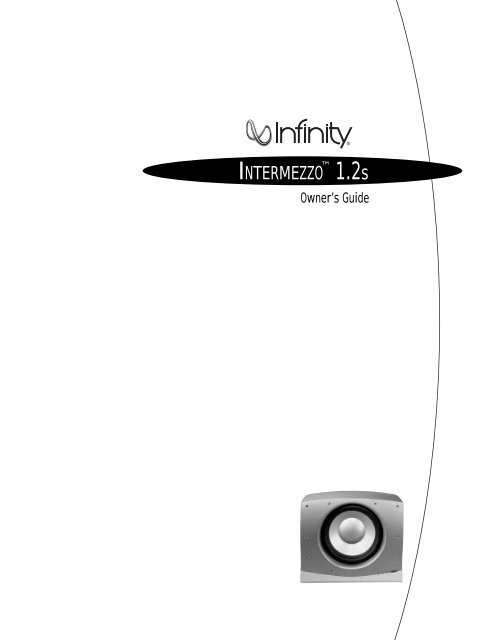
INTERMEZZO <br />
<strong>1.2s</strong><br />
Owner’s Guide
THIS INFINITY PRODUCT IS DESIGNED FOR 120-VOLT USE ONLY! FOR<br />
DETAILED SAFETY PRECAUTIONS, PLEASE SEE FOLLOWING PAGE IN THIS<br />
OWNER’S MANUAL FOR “IMPORTANT SAFETY INSTRUCTIONS.”<br />
ii INTERMEZZO <strong>1.2s</strong><br />
CAUTION<br />
RISK OF ELECTRIC SHOCK<br />
DO NOT OPEN<br />
WARNING: SHOCK HAZARD, DO NOT OPEN.<br />
AVIS: RISQUE DE CHOC ELECTRIQUE – NE PAS OUVRIR.<br />
CUIDADO: PELIGRO DE CHOQUE ELÉCTRICO – NO ABRIR.<br />
CAUTION: TO REDUCE THE RISK OF ELECTRIC SHOCK<br />
DO NOT REMOVE COVER (0R BACK)<br />
NO USER SERVICEABLE PARTS INSIDE<br />
REFER SERVICING TO QUALIFIED PERSONNEL<br />
The lightning flash with arrowhead symbol, within an equilateral triangle, is<br />
intended to alert the user to the presence of uninsulated “dangerous voltage” within<br />
the product’s enclosure that may be of sufficient magnitude to constitute a risk of<br />
electric shock to persons.<br />
The exclamation point within an equilateral triangle is intended to alert the user<br />
to the presence of important operating and maintenance (servicing) instructions in<br />
the literature accompanying the product.<br />
L’éclair avec le symbole de la flèche, placé dans les limites d’un triangel équilatéral est<br />
prévu pour avertir l’utilisateur de la présence de “tension dangereuse” non isolée dans<br />
l’enceinte du produit qui pourrait être d’une importance suffisante pour présenter un<br />
risque d’électrocution aux personnes.<br />
Le point d’exclamation dans un triangel équilateral est prévu pour avertir l’utilisateur<br />
de la présence d’instructions importantes pour les opérations et l’entretien (service)<br />
dans les manuels fournis avec l’appareil.<br />
ATTENTION: POUR EVITER LES CHOCS ELECTRIQUES, INTRODUIRE<br />
LA LAME LA PLUS LARGE DE LA FICHE DANS LA BORNE<br />
CORRESPONDANTE DE LA PRISE ET POUSSER JUSQUAU FOND.<br />
Este destello luminoso con un símbolo de punta de flecha dentro de un triángulo<br />
equilátero tiene el objectivo de alertar al usuario sobre la presencia de “voltaje<br />
peligroso” no aislado dentro de la caja del producto que puede ser de magnitud lo<br />
suficientemente grande para constituir un riesgo de choque eléctrico para las personas.<br />
Este punto de exclamación dentro de un triángulo equilátero tiene el objectivo de<br />
alertar al usuario sobre la existencia de instrucciones operativas y de mantenimiento<br />
(servicio) importantes en la literatura que acomaña el aparato.<br />
CUIDADO: PARA REDUCIR EL RIESGO DE CHOQUE ELÉCTRICO, NO<br />
RETIRE LA CUBIERTA (O RESPALDO). DENTRO NO HAY PEIZAS A LAS<br />
QUE EL USUARIO PUEDE DAR SERVICIO. REMITA EL SERVICIO AL<br />
PERSONAL DE SERVICIO CALIFICADO.
Read First!<br />
IMPORTANT SAFETY PRECAUTIONS<br />
CAUTION<br />
RISK OF ELECTRIC SHOCK<br />
DO NOT OPEN<br />
The lightning flash with arrowhead<br />
symbol within an equilateral triangle is<br />
intended to alert the user to the presence<br />
of uninsulated “dangerous voltage” within<br />
the product’s enclosure that may be of<br />
sufficient magnitude to constitute a risk of<br />
electric shock to persons.<br />
The exclamation point within an<br />
equilateral triangle is intended to alert the<br />
user to the presence of important<br />
operating and maintenance (servicing)<br />
instructions in the literature accompanying<br />
the appliance.<br />
1. Read Instructions. All the safety and operating<br />
instructions should be read before the product is<br />
operated.<br />
2. Retain Instructions. The safety and operating<br />
instructions should be retained for future reference.<br />
3. Heed Warnings. All warnings on the product and in<br />
the operating instructions should be adhered to.<br />
4. Follow Instructions. All operating and use<br />
instructions should be followed.<br />
5. Cleaning. Unplug this product from the wall outlet<br />
before cleaning. Do not use liquid cleaners or aerosol<br />
cleaners. Use a damp cloth for cleaning.<br />
6. Attachments. Do not use attachments not<br />
recommended by the product manufacturer,<br />
as they may cause hazards.<br />
7. Water and Moisture. To reduce the risk of fire or<br />
electric shock, do not use this product outdoors or<br />
near water–for example, near a bathtub, wash bowl,<br />
kitchen sink or laundry tub; in a wet basement; near a<br />
swimming pool; or the like.<br />
8. Accessories. Do not place this product on an<br />
unstable cart, stand, tripod, bracket or table.The<br />
product may fall, causing serious injury to a child or<br />
adult, and serious damage to the product. Use only<br />
with a cart, stand, tripod, bracket or table<br />
recommended by the manufacturer, or sold with the<br />
product. Any mounting of the product should follow the<br />
manufacturer’s instructions, and should use a<br />
mounting accessory recommended by the<br />
manufacturer.<br />
9. A Product and Cart Combination<br />
Should Be Moved with Care. Quick<br />
stops, excessive force and uneven<br />
surfaces may cause the product and<br />
cart combination to overturn.<br />
10. Ventilation. Slots and openings in the cabinet are<br />
provided for ventilation and to ensure reliable<br />
operation of the product and to protect it from<br />
overheating, and these openings must not be blocked<br />
or covered.The openings should never be blocked by<br />
placing the product on a bed, sofa, rug or other<br />
similar surface.This product should not be placed in a<br />
built-in installation, such as a bookcase or rack,<br />
unless proper ventilation is provided or the<br />
manufacturer’s instructions have been adhered to.<br />
11. Power Sources. This product should be operated<br />
only from the type of power source indicated on the<br />
marking label. If you are not sure of the type of power<br />
supply to your home, consult your product dealer or<br />
local power company. For products intended to operate<br />
from battery power, or other sources, refer to the<br />
operating instructions.<br />
12. Grounding or Polarization. This product may be<br />
equipped with a polarized alternating-current-line plug<br />
(a plug having one blade wider than the other).This<br />
plug will fit into the power outlet only one way.This is<br />
a safety feature. If you are unable to insert the plug<br />
fully into the outlet, try reversing the plug. If the plug<br />
should still fail to fit, contact your electrician to<br />
replace your obsolete outlet. Do not defeat the safety<br />
purpose of the polarized plug.<br />
13. Power-Cord Protection. Power-supply cords should<br />
be routed so that they are not likely to be walked on or<br />
pinched by items placed upon or against them, paying<br />
particular attention to cords at plugs, convenience<br />
receptacles, and the point where they exit from the<br />
product.<br />
14. Nonuse Periods. The power cord of the product<br />
should be unplugged from the outlet when left unused<br />
for long periods of time.<br />
15. Outdoor Antenna Grounding. If an outside antenna<br />
or cable system is connected to the product, be sure<br />
the antenna or cable system is grounded so as to<br />
provide some protection against voltage surges and<br />
built-up static charges. Article 810 of the National<br />
Electrical Code, ANSI/NFPA 70, provides information<br />
with regard to proper grounding of the mast and<br />
supporting structure, grounding of the lead-in wire to<br />
an antenna discharge unit, size of grounding<br />
conductors, location of antenna-discharge unit,<br />
connection to grounding electrodes, and requirements<br />
for the grounding electrode. See Figure A.<br />
16. Lightning. For added protection for this product<br />
during a lightning storm, or when it is left unattended<br />
and unused for long periods of time, unplug it from<br />
the wall outlet and disconnect the antenna or cable<br />
system.This will prevent damage to the product due to<br />
lightning and power-line surges.<br />
17. Power Lines. An outside antenna system should not<br />
be located in the vicinity of overhead power lines or<br />
other electric light or power circuits, or where it can<br />
fall into such power lines or circuits. When installing<br />
an outside antenna system, extreme care should be<br />
taken to keep from touching such power lines or<br />
circuits, as contact with them might be fatal.<br />
Figure A.<br />
Example of Antenna Grounding as per<br />
National Electrical Code ANSI/NFPA 70<br />
18. Overloading. Do not overload wall outlets, extension<br />
cords, or integral convenience receptacles, as this can<br />
result in a risk of fire or electric shock.<br />
19. Object and Liquid Entry. Never push objects of any<br />
kind into this product through openings, as they may<br />
touch dangerous voltage points or short-out parts that<br />
could result in a fire or electric shock. Never spill<br />
liquid of any kind on the product.<br />
20. Servicing. Do not attempt to service this product<br />
yourself, as opening or removing covers may expose<br />
you to dangerous voltage or other hazards. Refer all<br />
servicing to qualified service personnel.<br />
21. Damage Requiring Service. Unplug this product<br />
from the wall outlet and refer servicing to qualified<br />
service personnel under the following conditions:<br />
a. The power-supply cord or the plug has been<br />
damaged; or<br />
b. Objects have fallen onto, or liquid has been spilled<br />
into, the product; or<br />
c. The product has been exposed to rain or water; or<br />
d. The product does not operate normally when<br />
following the operating instructions. Adjust only those<br />
controls that are covered by the operating instructions,<br />
as an improper adjustment of other controls may<br />
result in damage and will often require extensive work<br />
by a qualified technician to restore the product to its<br />
normal operation; or<br />
e. The product has been dropped or damaged in any<br />
way; or<br />
f. The product exhibits a distinct change in<br />
performance; this indicates a need for service.<br />
22. Replacement Parts. When replacement parts are<br />
required, be sure the service technician has used<br />
replacement parts specified by the manufacturer or<br />
that have the same characteristics as the original<br />
part. Unauthorized substitutions may result in fire,<br />
electric shock or other hazards.<br />
23. Safety Check. Upon completion of any service or<br />
repairs to this product, ask the service technician to<br />
perform safety checks to determine that the product is<br />
in proper operating condition.<br />
24. Wall or Ceiling Mounting. The product should be<br />
mounted to a wall or ceiling only as recommended by<br />
the manufacturer.<br />
25. Heat. The product should be situated away from<br />
heat sources such as radiators, heat registers, stoves<br />
or other products (including amplifiers) that produce<br />
heat.<br />
Antenna Lead-In Wire<br />
Ground Clamp<br />
Antenna Discharge Unit (NEC Section 810-20)<br />
Grounding Conductors (NEC Section 810-21)<br />
Electric Service Equipment<br />
Ground Clamps<br />
Power Service Grounding Electrode System<br />
(NEC Art. 250, Part H)<br />
INTERMEZZO <strong>1.2s</strong><br />
iii
iv INTERMEZZO <strong>1.2s</strong><br />
INTERMEZZO 1.2S OWNER’S GUIDE<br />
Table of Contents<br />
ii Caution<br />
iii Important Safety Precautions<br />
1 Technology<br />
1 Ceramic Metal Matrix Diaphragms (C.M.M.D.)<br />
1 Room-Friendly Acoustical Design<br />
2 Unpacking the Product/Included Accessories<br />
3 Placement<br />
4 Controls and Connections<br />
5 Connection Methods 1–4<br />
8 Operation<br />
9 Room Adaptive Bass Optimization System (R.A.B.O.S.)<br />
10 Contents of the R.A.B.O.S.Test CD<br />
10 R.A.B.O.S. Sound-Level Meter (RSLM)<br />
15 What You Measure, What To Do<br />
18 Adjusting the R.A.B.O.S. Equalizer<br />
19 Final System Balance<br />
20 Maintenance and Service<br />
21 Specifications<br />
22 R.A.B.O.S. Measurement Templates
TECHNOLOGY<br />
<strong>Intermezzo</strong> Series loudspeakers incorporate several innovative<br />
technologies that, when implemented by exceptional engineering<br />
talent after hours upon hours of subjective listening evaluations,<br />
result in a loudspeaker that realistically and accurately reproduces<br />
the signal source with minimal distortion and coloration.<br />
Ceramic Metal Matrix Diaphragms (C.M.M.D.)<br />
For decades, loudspeaker engineers have known that the ideal<br />
transducer should be stiff, yet light, and have high internal<br />
damping (damping is a material’s ability to absorb energy).<br />
Infinity’s C.M.M.D. transducer is a significant advance in<br />
transducer technology. Ceramic, a class of material new to<br />
loudspeakers, offers better performance than that of other<br />
materials. Ceramic is stiffer than metals and lighter than plastics<br />
and typical composite materials; it also offers improved damping.<br />
These ceramic-based transducers take us a giant step closer to<br />
the ever-elusive “ideal transducer.”<br />
In tweeters, C.M.M.D. technology offers stiffness and damping<br />
superior to that of traditional metals and soft-dome materials.<br />
In woofer and midrange applications, it offers accurate pistonic<br />
operation over the entire frequency range of the driver,<br />
completely eliminating coloration due to cone breakup and<br />
dramatically reducing distortion. And when ceramic-metal-matrix<br />
transducers are exposed to moisture, sunlight or extreme<br />
temperatures, their performance does not deteriorate.<br />
In addition to ceramic diaphragms, all the transducers incorporate<br />
magnetic shielding and rigid cast-frames that, through our FEA<br />
computer modeling and scanning-laser-vibrometer measurements,<br />
have been optimized to reduce resonances.This ensures minimal<br />
distortion and incomparable performance.<br />
Amplifier<br />
BASH ® is an amplifier-power-supply technology that increases<br />
efficiency by reducing power dissipation in the output section.<br />
The BASH topology uses a high-efficiency, fast-response, switchmode<br />
power supply that provides the main voltage rails for a<br />
linear Class-AB amplifier. By varying the output of the power<br />
supply with the audio signal being amplified, a constant voltage<br />
drop across the output transistors of the linear amplifier can be<br />
maintained.This means that the power dissipation in the output<br />
transistors is greatly reduced.<br />
The result is an extremely efficient audio amplifier that does not<br />
compromise audio performance.<br />
Room-Friendly Acoustical Design<br />
Driver quality is not the only requirement for exceptional<br />
performance. Infinity’s engineers understand that the room in<br />
which the loudspeaker is placed can greatly affect its<br />
performance.To ensure that <strong>Intermezzo</strong> Series loudspeakers will<br />
sound exceptional in even the most unexceptional listening<br />
environment, Infinity has developed the proprietary Room Adaptive<br />
Bass Optimization System (R.A.B.O.S.). With a single band of<br />
parametric equalization, the <strong>Intermezzo</strong> <strong>1.2s</strong> can be adjusted to<br />
tame any problematic room bass resonances below 80Hz.<br />
We hope you enjoyed this brief introduction to the technology<br />
of <strong>Intermezzo</strong> loudspeakers. If you would like to further explore<br />
their technology and design, please ask your Infinity dealer<br />
for the C.M.M.D. and R.A.B.O.S. White Papers.The White<br />
Papers can also be downloaded from Infinity’s Web site at<br />
www.infinitysystems.com.<br />
INTERMEZZO <strong>1.2s</strong><br />
1
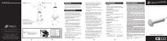
Unpacking the Product<br />
Finish unpacking the speakers and check the contents. If you<br />
suspect damage from transit, report it immediately to your dealer<br />
and/or delivery service. Keep the shipping carton and packing<br />
materials for future use.<br />
Included Accessories . . .<br />
R.A.B.O.S. Kit (1)<br />
-1<br />
-2<br />
-3<br />
-4<br />
-5<br />
-6<br />
-7<br />
-8<br />
-9<br />
-10<br />
-11<br />
-13<br />
-15<br />
-18<br />
U-R<br />
Batt<br />
Power<br />
Grille Decorative<br />
Side Panel<br />
AC Cord<br />
Sound-Level Meter R.A.B.O.S. Test CD<br />
Graph Templates Bandwidth Selector<br />
Adjustment Key<br />
2 INTERMEZZO <strong>1.2s</strong>
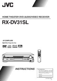
PLACEMENT<br />
Since the installation of a subwoofer can be somewhat more<br />
complicated than installing full-range speakers, it is essential<br />
that you read this section very carefully prior to connecting the<br />
subwoofer to your system. Should you have questions relating to<br />
your installation, it is advisable to call either your dealer or<br />
Infinity’s Customer Service Department for advice.<br />
The performance of the subwoofer is directly related to its<br />
placement in the listening room and how you align the subwoofer<br />
with its satellite speakers. Setting the volume of the subwoofer in<br />
relationship to the left and right speakers is also of critical<br />
importance because it is essential that the subwoofer integrates<br />
smoothly with the entire system. Setting the subwoofer’s volume<br />
level too high will result in an overpowering, boomy bass. Setting<br />
the volume level too low will negate the effect of the subwoofer.<br />
Generally speaking, the closer the subwoofer is placed to a room<br />
boundary (walls and corners), the more bass output there will be.<br />
If you are hearing too much low-frequency sound in relation to<br />
the rest of the program material, move the subwoofer further<br />
from the corner or wall. Conversely, if, after making all adjustments,<br />
there is still not enough low-frequency energy, move the<br />
subwoofer closer to a wall or corner.<br />
Here are several additional facts on installation that may prove<br />
useful. It is generally believed by most audio authorities that low<br />
frequencies (below 125Hz) are nondirectional and, therefore,<br />
placement of a subwoofer within any listening room is not<br />
critical. While in theory it is true that the larger wavelengths, of<br />
extremely low frequencies, are basically nondirectional, the fact<br />
is that when installing a subwoofer within the limited confines of<br />
a room, reflections, standing waves and absorptions generated<br />
within the room will strongly influence the performance of any<br />
subwoofer system.As a result, specific location of the subwoofer<br />
becomes important, and we strongly recommend that you<br />
experiment with placement before choosing a final location.<br />
Placement will depend upon your room and the amount and<br />
quality of bass required (for example, whether or not your room<br />
permits placement of the subwoofer near either satellite).<br />
FIGURE 1<br />
FIGURE 2<br />
LEFT<br />
SURROUND<br />
LEFT<br />
CHANNEL<br />
FRONT<br />
LEFT<br />
➢<br />
➢<br />
SOFA<br />
TV<br />
CENTER<br />
SOFA<br />
➢<br />
➢<br />
FRONT<br />
RIGHT<br />
INTERMEZZO <strong>1.2s</strong><br />
RIGHT<br />
CHANNEL<br />
SUB<br />
SUB<br />
RIGHT<br />
SURROUND<br />
3
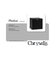
Rear Panel<br />
120V – 60HZ 6A<br />
Front Panel<br />
AC-Cord Input<br />
Power Switch<br />
Speaker-Level Inputs<br />
Speaker-Level Outputs<br />
High-Level High-Pass Filter Switch<br />
Low-Level-Input Connectors<br />
Low-Level-Output Connectors<br />
Phase Switch<br />
<br />
POWER<br />
<br />
Low-Pass Filter Switch<br />
F<br />
<br />
Variable Low-Pass Filter Adjustment<br />
4 INTERMEZZO <strong>1.2s</strong><br />
CONTROLS AND CONNECTIONS<br />
AC FUSE<br />
6A 250V<br />
L<br />
<br />
W<br />
<br />
+ L –<br />
+ R –<br />
– L +<br />
INPUTS OUTPUTS<br />
<br />
›<br />
CAUTION<br />
RISK OF ELECTRIC SHOCK DO NOT OPEN<br />
RISQUE DE CHOC ELECTRIQUE NE PAS OUVRIR<br />
– R +<br />
<br />
L<br />
ON OFF 0 180 ON OFF<br />
HIGH-LEVEL<br />
HIGH-PASS<br />
FILTER<br />
LOW-<br />
LEVEL<br />
INPUT<br />
Subwoofer-Level Control<br />
R.A.B.O.S. Controls<br />
Center-Frequency Adjustment<br />
R.A.B.O.S. Level<br />
R<br />
LOW-<br />
LEVEL<br />
OUTPUT<br />
Bandwidth Adjustment<br />
INTERMEZZO <strong>1.2s</strong><br />
PHASE<br />
LOW-PASS<br />
FILTER<br />
80<br />
50 130<br />
LOW-PASS<br />
FILTER
The Infinity <strong>Intermezzo</strong> <strong>1.2s</strong> offers unprecedented flexibility for<br />
connecting the system to any type of audio or home-theater system.<br />
Consult the table at right to determine which system description<br />
most closely matches your own, then follow the hook-up method<br />
corresponding to that system.<br />
If none of these system configurations seem to match yours,<br />
consult your dealer or Infinity customer service for direction on<br />
how best to hook up your system.<br />
For Methods 2, 3a, 3b and 4, make sure all bass-management<br />
features are properly set.The Audio channels should all be set to<br />
“Small”or “High-Pass” and the subwoofer set to “On.”<br />
1. LOOSEN TERMINALS<br />
2.<br />
3.<br />
4.<br />
Method 1<br />
INSERT BARE END;<br />
TIGHTEN TERMINALS<br />
SET LOW-PASS<br />
FILTER TO “ON”<br />
SET HIGH-PASS SWITCH <br />
TO “ON” OR “OFF” (SEE P. 8)<br />
BLACK = –<br />
RED = +<br />
NO STRIPE = – STRIPE = +<br />
120V – 60HZ 6A<br />
POWER<br />
AC FUSE<br />
6A 250V<br />
AMPLIFIER/RECEIVER<br />
LEFT SPEAKER RIGHT<br />
OUTPUTS<br />
+<br />
(ONE CHANNEL SHOWN)<br />
+ L –<br />
INPUTS<br />
+ R –<br />
System Type Connection Methods<br />
2-Channel receiver or integrated amplifier<br />
that has no subwoofer output or<br />
Pre-out/Main-In connectors 1<br />
2-Channel receiver or integrated amplifier<br />
with preamp output and input connectors 2<br />
2-Channel system with separate preamplifier<br />
and power amplifier 2<br />
Dolby* Pro Logic* with THX, ® Dolby Digital,<br />
or DTS ® receiver with a filtered subwoofer<br />
(or LFE) output connector 3a<br />
Dolby Digital or DTS processor with separate<br />
power amplifiers or multichannel amplifier 3b<br />
Non-THX certified Dolby Pro Logic receiver<br />
with full-range subwoofer outputs 4<br />
– – +<br />
– L +<br />
CAUTION<br />
RISK OF ELECTRIC SHOCK DO NOT OPEN<br />
RISQUE DE CHOC ELECTRIQUE NE PAS OUVRIR<br />
OUTPUTS<br />
– R +<br />
+<br />
L<br />
ON OFF 0 180 ON OFF<br />
HIGH-LEVEL<br />
HIGH-PASS<br />
FILTER<br />
–<br />
RIGHT<br />
SPEAKER<br />
LOW-<br />
LEVEL<br />
INPUT<br />
R<br />
LOW-<br />
LEVEL<br />
OUTPUT<br />
INTERMEZZO <strong>1.2s</strong><br />
PHASE<br />
LOW-PASS<br />
FILTER<br />
80<br />
50 130<br />
LOW-PASS<br />
FILTER<br />
INTERMEZZO <strong>1.2s</strong><br />
5
Method 2<br />
SET LOW-PASS<br />
FILTER TO “ON”<br />
Method 3a<br />
SET LOW-PASS<br />
FILTER TO “OFF”<br />
6 INTERMEZZO <strong>1.2s</strong><br />
120V – 60HZ 6A<br />
(ONE CHANNEL SHOWN)<br />
PREAMP OUTPUTS<br />
L<br />
R<br />
120V – 60HZ 6A<br />
POWER<br />
AC FUSE<br />
6A 250V<br />
POWER<br />
AC FUSE<br />
6A 250V<br />
+ L –<br />
(ONE CHANNEL SHOWN)<br />
SURROUND RECEIVER<br />
SUBWOOFER (LFE)<br />
OUTPUT<br />
–<br />
+ L –<br />
+ R –<br />
FRONT SPEAKER<br />
OUTPUTS<br />
– L +<br />
INPUTS OUTPUTS<br />
+ R –<br />
– R +<br />
CAUTION<br />
RISK OF ELECTRIC SHOCK DO NOT OPEN<br />
RISQUE DE CHOC ELECTRIQUE NE PAS OUVRIR<br />
AMPLIFIER INPUTS<br />
L<br />
R<br />
+<br />
– L +<br />
INPUTS OUTPUTS<br />
– R +<br />
CAUTION<br />
RISK OF ELECTRIC SHOCK DO NOT OPEN<br />
RISQUE DE CHOC ELECTRIQUE NE PAS OUVRIR<br />
TO MAIN SPEAKERS<br />
L<br />
ON OFF 0 180 ON OFF<br />
HIGH-LEVEL<br />
HIGH-PASS<br />
FILTER<br />
L<br />
ON OFF 0 180 ON OFF<br />
HIGH-LEVEL<br />
HIGH-PASS<br />
FILTER<br />
LOW-<br />
LEVEL<br />
INPUT<br />
R<br />
LOW-<br />
LEVEL<br />
INPUT<br />
LOW-<br />
LEVEL<br />
OUTPUT<br />
R<br />
INTERMEZZO <strong>1.2s</strong><br />
LOW-<br />
LEVEL<br />
OUTPUT<br />
PHASE<br />
INTERMEZZO <strong>1.2s</strong><br />
PHASE<br />
LOW-PASS<br />
FILTER<br />
LOW-PASS<br />
FILTER<br />
80<br />
50 130<br />
LOW-PASS<br />
FILTER<br />
80<br />
50 130<br />
LOW-PASS<br />
FILTER
Method 3b<br />
SET LOW-PASS<br />
FILTER TO “OFF”<br />
Method 4<br />
SET LOW-PASS<br />
FILTER TO “ON”<br />
120V – 60HZ 6A<br />
120V – 60HZ 6A<br />
TO MAIN<br />
SPEAKERS<br />
POWER<br />
AC FUSE<br />
6A 250V<br />
POWER<br />
AC FUSE<br />
6A 250V<br />
AMPLIFIER PROCESSOR<br />
RECEIVER<br />
SUBWOOFER<br />
OUTPUTS<br />
L<br />
R<br />
SPEAKER<br />
OUTPUT<br />
– +<br />
L<br />
R<br />
(ONE CHANNEL SHOWN)<br />
+ L –<br />
+ R –<br />
INPUT<br />
+ L –<br />
+ R –<br />
SPEAKER<br />
OUTPUTS<br />
RIGHT<br />
– +<br />
– L +<br />
INPUTS OUTPUTS<br />
– R +<br />
CAUTION<br />
RISK OF ELECTRIC SHOCK DO NOT OPEN<br />
RISQUE DE CHOC ELECTRIQUE NE PAS OUVRIR<br />
– L +<br />
INPUTS OUTPUTS<br />
– R +<br />
CAUTION<br />
RISK OF ELECTRIC SHOCK DO NOT OPEN<br />
RISQUE DE CHOC ELECTRIQUE NE PAS OUVRIR<br />
(ONE CHANNEL SHOWN)<br />
SUBWOOFER (LFE)<br />
OUTPUT<br />
L<br />
ON OFF 0 180 ON OFF<br />
HIGH-LEVEL<br />
HIGH-PASS<br />
FILTER<br />
TO MAIN SPEAKERS<br />
L<br />
ON OFF 0 180 ON OFF<br />
HIGH-LEVEL<br />
HIGH-PASS<br />
FILTER<br />
FRONT CHANNEL<br />
OUTPUT<br />
L<br />
R<br />
LOW-<br />
LEVEL<br />
INPUT<br />
LOW-<br />
LEVEL<br />
INPUT<br />
R<br />
R<br />
LOW-<br />
LEVEL<br />
OUTPUT<br />
LOW-<br />
LEVEL<br />
OUTPUT<br />
INTERMEZZO <strong>1.2s</strong><br />
PHASE<br />
INTERMEZZO <strong>1.2s</strong><br />
PHASE<br />
LOW-PASS<br />
FILTER<br />
LOW-PASS<br />
FILTER<br />
LOW-PASS<br />
FILTER<br />
LOW-PASS<br />
FILTER<br />
INTERMEZZO <strong>1.2s</strong><br />
80<br />
80<br />
50 130<br />
50 130<br />
7
Power On<br />
Plug your subwoofer’s AC cord into a wall outlet. Do not use the<br />
outlets on the back of the receiver.<br />
Initially set the subwoofer’s Level Control to the “O”position.<br />
Turn on your sub by pressing the power button on the rear<br />
panel.<br />
Turn on your entire audio system and start a CD or movie soundtrack<br />
at a moderate level.<br />
Adjust Gain<br />
Turn your subwoofer’s Level Control up to the “5”position<br />
(half way). If no sound emanates from the subwoofer, check the<br />
AC-line cord and input cables.Are the connectors on the cables<br />
making proper contact? Is the AC plug connected to a “live”<br />
receptacle? Has the power button been pressed to the “On”<br />
position? (Note:The Level Control on the front panel will turn<br />
green when the power is on.) Once you have confirmed that the<br />
subwoofer is active, proceed by playing a CD, record or cassette.<br />
Use a selection that has ample bass information.<br />
Set the overall volume control of the preamplifier or stereo to a<br />
comfortable level. Adjust the subwoofer’s Level Control until<br />
you obtain a pleasing blend of bass. Bass response should not<br />
overpower the room but rather be adjusted so there is a<br />
harmonious blend across the entire musical range. Many users<br />
have a tendency to set the subwoofer volume too loud,<br />
adhering to the belief that a subwoofer is there to produce lots<br />
of bass.This is not entirely true. A subwoofer is there to enhance<br />
bass, extending the response of the entire system so the bass<br />
can be felt as well as heard. However, overall balance must<br />
be maintained or the music will not sound natural. An<br />
experienced listener will set the volume of the subwoofer so<br />
its impact on bass response is always there but never obtrusive.<br />
8 INTERMEZZO <strong>1.2s</strong><br />
OPERATION<br />
Crossover Adjustments<br />
If you are using Method 1 as your connection method, you need to<br />
set the High-Level High-Pass Filter to “On”or “Off.”When on,<br />
this adjustment limits the low frequencies that your main speakers<br />
will reproduce. If you would like your main speakers to also<br />
reproduce frequencies below 80Hz, you may set this switch to<br />
“Off.”If you are using speakers that do not reproduce low<br />
frequencies well, we recommend that you set the switch to “On.”<br />
Low-Pass Filter Adjustment Control – The Low-Pass Control<br />
determines the highest frequency at which the subwoofer<br />
reproduces sounds. If your main speakers can comfortably<br />
reproduce some low-frequency sounds, set this control to a<br />
lower frequency setting, between 50Hz – 100Hz.This will<br />
concentrate the subwoofer’s efforts on the ultradeep bass<br />
sounds required by today’s films and music. If you are using<br />
smaller bookshelf speakers that do not extend to the lower bass<br />
frequencies, set the Low-Pass Filter Adjustment Control to a<br />
higher setting, between 120Hz – 150Hz.<br />
Note: This control will have no effect if the Low-Pass Filter<br />
Switch is set to “Off.”If you have a Dolby Digital or DTS<br />
processor/receiver, the Low-Pass Frequency is set by the<br />
processor/receiver. So you should leave the Low-Pass Filter<br />
Switch in the “Off”position. Consult your owner’s manual to<br />
learn how to view or change this setting.<br />
Phase Control<br />
The Phase Switch determines whether the subwoofer<br />
speaker’s piston-like action moves in and out with the main<br />
speakers, 0˚, or opposite the main speakers, 180˚. Proper phase<br />
adjustment depends on several variables such as room size,<br />
subwoofer placement and listener position. Adjust the phase<br />
switch to maximize bass output at the listening position.<br />
Final Positioning<br />
After correctly connecting the <strong>Intermezzo</strong> <strong>1.2s</strong> and verifying that<br />
both the subwoofer and main speakers are playing, it is time to<br />
optimize the system for your particular listening room. Earlier,<br />
you placed the subwoofer in its general location. Finding the<br />
exact location for optimum performance sometimes only involves<br />
moving the speakers up to a few inches in any direction. We urge<br />
you, therefore, to experiment with placement until your speakers<br />
deliver their full potential.
RO<strong>OM</strong> ADAPTIVE BASS OPTIMIZATION SYSTEM<br />
Infinity R.A.B.O.S. is a simple-to-use, yet sophisticated, lowfrequency<br />
calibration system. It is designed to work in<br />
conjunction with Infinity <strong>Intermezzo</strong> self-amplified subwoofers.<br />
The <strong>Intermezzo</strong> <strong>1.2s</strong> subwoofer contains a parametric equalizer<br />
that you will adjust as indicated by the R.A.B.O.S. test results.<br />
Following these instructions, you will optimize the <strong>Intermezzo</strong><br />
subwoofers’ response characteristics to complement their<br />
environment.This will dramatically improve the sound of your<br />
system.The optimization process takes less than 30 minutes.<br />
The R.A.B.O.S. Kit Includes<br />
the Following Components:<br />
• Specialized Sound-Level Meter<br />
• Test CD<br />
• Instructions<br />
• Measurement Templates<br />
• Width Selector<br />
• Adjustment “Key”<br />
What R.A.B.O.S. Does<br />
The Test CD provides specially designed signals you will use<br />
while performing measurements.The sound-level meter provided<br />
is used to “acquire”the information needed for adjustments.You<br />
will create a response plot on the Measurement Template. Using<br />
the Width Selector, you will then determine the appropriate<br />
equalizer settings.The “Key”is used to adjust the parametric<br />
equalizer built into the <strong>Intermezzo</strong> subwoofer. After adjustment,<br />
the test sequence is repeated to confirm your settings.<br />
The R.A.B.O.S. Goal<br />
It is a fact of audio that what we hear at low frequencies is<br />
determined as much or more by the listening room than by the<br />
loudspeaker itself. Placement of the loudspeakers and listeners<br />
and the acoustical characteristics of the room surfaces are all<br />
important determinants of bass quantity and quality. In most<br />
practical situations, there is little that can be done about this,<br />
except for patient trial-and-error repositioning of the<br />
loudspeakers and listeners. Usually, the practical constraints of a<br />
living space and the impracticality of massive acoustical<br />
treatment mean that equalization is the only practical solution.<br />
Professional sound engineers routinely employ sophisticated<br />
measurement systems and equalizers to optimize speakers to the<br />
installation.This has never been practical for the home<br />
audiophile.This is why R.A.B.O.S. was created. R.A.B.O.S. enables<br />
you to identify the dominant low-frequency response<br />
characteristic of your room. Once you know the problem,<br />
R.A.B.O.S. provides the tools needed to optimize the lowfrequency<br />
characteristics of the speakers to the room they are<br />
in, exactly as the professional sound engineers do it.<br />
Performing R.A.B.O.S.Tests<br />
These instructions assume you have already installed your<br />
<strong>Intermezzo</strong> subwoofer according to the information provided in<br />
the Owner’s Guide. It is also assumed that all equipment in your<br />
entertainment system is interconnected properly and is in good<br />
operating condition.<br />
Preparations<br />
Before beginning R.A.B.O.S. tests, please check the following:<br />
• Make sure all three R.A.B.O.S. controls on the <strong>Intermezzo</strong> <strong>1.2s</strong><br />
are turned fully clockwise.<br />
• Make sure the loudness contour (if any) on your receiver/<br />
processor/preamp is turned off.<br />
• Set the tone controls (Bass and Treble) to their center or<br />
flat positions.<br />
• Bypass all surround and effects features of your receiver/<br />
processor/preamp or set to Stereo Bypass.<br />
• If you are using a multichannel surround processor or<br />
receiver, make sure all bass-management features are properly<br />
set.The Audio channels should all be set to “Small”or “High-<br />
Pass” and the subwoofer set to “On.”<br />
You must have a CD player in the system. A CD player remote<br />
control is quite convenient but not essential.<br />
For best results, it is recommended that all major furnishings are<br />
in place and that all doors and windows in the listening area are<br />
in their normal positions.That is, if you normally listen to music<br />
with all doors closed, then this is how they should be during this<br />
procedure.<br />
Try to minimize ambient noise while running tests.Turn off all<br />
major appliances and any air conditioning or furnace fans.These<br />
can create significant subsonic noise that may be barely<br />
perceptible but which can wreak havoc on low-frequency<br />
measurements.<br />
Critical information is highlighted with this mark:<br />
Helpful hints are marked with this symbol:<br />
INTERMEZZO <strong>1.2s</strong><br />
9
Contents of the R.A.B.O.S. Test CD<br />
Track Title<br />
1 Welcome<br />
2 Set System Test Level<br />
3 Set Subwoofer Test Level<br />
4 100Hz Test<br />
5 95Hz Test<br />
6 90Hz Test<br />
7 85Hz Test<br />
8 80Hz Test<br />
9 77Hz Test<br />
10 72Hz Test<br />
11 66Hz Test<br />
12 63Hz Test<br />
13 56Hz Test<br />
14 52Hz Test<br />
15 49Hz Test<br />
16 46Hz Test<br />
17 43Hz Test<br />
18 40Hz Test<br />
19 38Hz Test<br />
20 35Hz Test<br />
21 30Hz Test<br />
22 26Hz Test<br />
23 24Hz Test<br />
24 22Hz Test<br />
25 21Hz Test<br />
26 20Hz Test<br />
27 Intro to Quick Retest<br />
28 Quick Retest 100Hz<br />
29 Quick Retest 95Hz<br />
30 Quick Retest 90Hz<br />
31 Quick Retest 85Hz<br />
Tracks 53–62 of the R.A.B.O.S.Test CD are test tones that can be<br />
used for general diagnostics of your system.They are not used<br />
for R.A.B.O.S. settings.<br />
THE R.A.B.O.S. SOUND-LEVEL METER (RSLM)<br />
The RSLM is a battery-operated, handheld, acoustic measurement<br />
device specifically designed for Infinity R.A.B.O.S. On the face of<br />
the instrument is a light-emitting diode (LED) bar graph that<br />
indicates relative sound level.There are also indicators for<br />
power-on, out-of-range signals and a low battery.<br />
FIGURE 3<br />
R.A.B.O.S. Sound-Level Meter<br />
10 INTERMEZZO <strong>1.2s</strong><br />
-1<br />
-2<br />
-3<br />
-4<br />
-5<br />
-6<br />
-7<br />
-8<br />
-9<br />
-10<br />
-11<br />
-13<br />
-15<br />
-18<br />
U-R<br />
Batt<br />
Power<br />
Track Title<br />
32 Quick Retest 80Hz<br />
33 Quick Retest 77Hz<br />
34 Quick Retest 72Hz<br />
35 Quick Retest 66Hz<br />
36 Quick Retest 63Hz<br />
37 Quick Retest 56Hz<br />
38 Quick Retest 52Hz<br />
39 Quick Retest 49Hz<br />
40 Quick Retest 46Hz<br />
41 Quick Retest 43Hz<br />
42 Quick Retest 40Hz<br />
43 Quick Retest 38Hz<br />
44 Quick Retest 35Hz<br />
45 Quick Retest 30Hz<br />
46 Quick Retest 26Hz<br />
47 Quick Retest 24Hz<br />
48 Quick Retest 22Hz<br />
49 Quick Retest 21Hz<br />
50 Quick Retest 20Hz<br />
51 Final System Level Adjustment<br />
52 Final Subwoofer Level Adjustment<br />
53 Wide Band Pink Noise, Left<br />
54 Wide Band Pink Noise,L+R<br />
55 Wide Band Pink Noise, Right<br />
56 Wide Band Pink Noise, L-R<br />
57 Wide Band Pink Noise, Uncorrelated<br />
58 1 to 4kHz Pink Noise, Left<br />
59 1 to 4kHz Pink Noise, L+R<br />
60 1 to 4kHz Pink Noise, Right<br />
61 1 to 4kHz Pink Noise, Left-R<br />
62 1 to 4kHz Pink Noise, Uncorrelated<br />
Power is switched on or off by pressing the button directly below<br />
the bar-graph window.When the unit is on, one or more LEDs will<br />
always be illuminated.The function of the LEDs is described in the<br />
following section.<br />
FIGURE 4<br />
RSLM bar-graph indications<br />
On<br />
Under-range Measurement<br />
In-range<br />
Over-range Low<br />
Battery<br />
• Power-On/Low Signal: This is indicated by the illumination of<br />
any LED on the bar graph. If the sound level in the room is below<br />
the measurement range of the instrument, a green LED near the<br />
bottom of the bar graph will be illuminated.<br />
• Normal Measurements: When the sound level is within the<br />
range of the RSLM, the green LED will be off and one of the red<br />
LEDs in the bar graph will be illuminated, indicating the relative<br />
sound level, in decibels (dB).<br />
• Over-Range: If the sound level exceeds the range of the meter,<br />
0dB through -5 will all light simultaneously.<br />
• Low Battery: When the battery voltage is too low for accurate<br />
measurements, an LED at the bottom of the bar graph will be<br />
illuminated. Replace the battery.<br />
Do not attempt measurements when this light is on.<br />
RSLM Placement<br />
Determine where in the room you are most likely to sit when<br />
listening to music or watching a movie.This is where you will<br />
want to hold the RSLM during measurements.The RSLM should<br />
be oriented so it can be easily read and held at your seated ear<br />
level during tests.<br />
You must use this same position for all tests.<br />
The RSLM can be mounted on a standard camera tripod.<br />
This will ensure the best results.
Initial System-Level Setting<br />
The following steps will set the playback level of the system to<br />
the correct level for all tests that follow.<br />
Turn the system volume to minimum.<br />
Cue the R.A.B.O.S.Test CD to Track 2 and press Pause II.This<br />
track will produce band-limited pink noise in both the left and<br />
right channels.<br />
Press Play › . With the RSLM positioned as described above,<br />
increase the system volume until the RSLM display indicates -10dB.<br />
See Figure 5.<br />
FIGURE 5<br />
RSLM indicating the correct system<br />
level to begin tests (-10dB)<br />
When you have completed this<br />
adjustment, press Pause II.<br />
Setting the Subwoofer Test Level<br />
Each of the following test tracks is about one minute<br />
long.This is normally much longer than required. Press Pause II<br />
or advance to the next test as soon as you are ready.<br />
This step will set the subwoofer levels for measurement<br />
purposes.The objective is to scale the subwoofers’ output to<br />
make full use of the RSLM indicator range. Scaling is optimum<br />
when a 0dB reading is observed on the highest peak without<br />
triggering the over-range indication. Later, you will rebalance<br />
the subwoofers to the main speakers.<br />
The <strong>Intermezzo</strong> subwoofers should be shipped with the three<br />
R.A.B.O.S. controls, , and , set to fully clockwise<br />
positions, and all measurements should be conducted with their<br />
level controls in this position. Confirm this setting before you<br />
begin this test.The gain control should be set to the mid<br />
position (5).<br />
Cue Track 3 and Pause II.Track 3 continuously steps through all<br />
subwoofer test tones for approximately 1 minute. Each tone will<br />
play just long enough for the RSLM to give a stable reading.<br />
To get accurate measurements, it is necessary to play<br />
the woofers quite loud.The 0dB indication is about 94dB. At this<br />
level, frequencies below 100Hz can cause doors, windows,<br />
furnishings and other objects in the room to vibrate.This<br />
frequently results in clearly audible buzzes and/or rattles that<br />
come and go as each test tone plays. Strong buzzes not only<br />
sound bad, they can cause measurement errors. If you hear a<br />
buzz or rattle during this test, it is highly recommended that you<br />
locate the source and eliminate its effects.This is actually a<br />
valuable room-diagnostic tool.<br />
Press Play ›. As Track 3 plays, watch the RSLM carefully. Watch<br />
for peak readings.The peak reading may be no more than a brief<br />
flash. Readjust the subwoofer’s gain control until the peak<br />
level observed is 0dB without triggering the over-range<br />
indication. See Figure 6.<br />
FIGURE 6<br />
Adjusting the subwoofer levels for a 0dB peak<br />
When finished, press Pause II.<br />
Performing Low-Frequency Measurements<br />
Read the following instructions fully before beginning<br />
tests.<br />
For the following steps, you will need a Measurement Template<br />
and a pencil.<br />
FIGURE 7<br />
R.A.B.O.S. Measurement Template<br />
INTERMEZZO <strong>1.2s</strong><br />
11
Each of the following tracks produces a low-frequency test tone.<br />
The range of these tests is from 100Hz down to 20Hz.The<br />
frequency of each test is announced before it begins.The first<br />
test is the highest frequency (100Hz); therefore, you will be<br />
marking the template from right to left. Each frequency point is<br />
listed across the bottom of the Measurement Template (this is<br />
called the X-axis). See Figure 7 on the previous page.The<br />
vertical scale on the left side of the template indicates relative<br />
level, in dBs (the Y-axis).The template’s vertical scale matches<br />
that of the RSLM bar graph.<br />
Cue Track 4 and Pause II.<br />
From now on, you will want to keep your CD player’s<br />
remote control handy.<br />
Press Play . As Track 4 plays, observe the level indicated on<br />
the RSLM.<br />
EXAMPLE:The test frequency is 100Hz and the level indicated is<br />
-2dB. Find the intersection of 100Hz (X-axis) and -2dB (Y-axis).<br />
Place a dot at that point. See Figure 8.<br />
FIGURE 8<br />
▼<br />
Locating a test point<br />
It takes a few seconds for the RSLM reading to stabilize,<br />
especially at very low frequencies. Don’t rush. Give each test<br />
adequate time for the meter to stabilize.<br />
At the bottom of the bar graph is a green “ON”LED.This LED is<br />
illuminated whenever the sound level is below the measuring<br />
range of the RSLM. If this occurs during a test, place a dot at the<br />
intersection of the test frequency and the bottom frame of the<br />
template. See Figure 9.<br />
FIGURE 9<br />
Indicating an under-range test<br />
12 INTERMEZZO <strong>1.2s</strong><br />
2<br />
When finished, press Skip to advance to the next test.<br />
Repeat the process described above for Tracks 5 through 26.<br />
When you have completed the 23 measurements, you are ready to<br />
analyze the data and make corrective adjustments.The completed<br />
Measurement template will look something like the example in<br />
Figure 10.<br />
FIGURE 10<br />
Completed R.A.B.O.S. template<br />
Now connect the dots as shown in Figure 11.<br />
This will make interpretation of the data much easier.<br />
FIGURE 11<br />
▼<br />
Test example with dots connected
What Does a Parametric Equalizer Do?<br />
The R.A.B.O.S. system uses one band of parametric equalization<br />
for response correction. Parametric equalizers are the most<br />
versatile class of filters.The effect an equalizer will have on the<br />
signal is dependent on three parameters.<br />
Frequency: The equalizer will have maximum effect at one<br />
frequency, usually described as the center frequency.<br />
Level: This refers to the amount of cut (in dBs) the equalizer<br />
is set for.<br />
Bandwidth: Defines the range of frequencies over which the<br />
equalizer will have an effect. On the <strong>Intermezzo</strong>, this adjustment<br />
is abbreviated as “Width.”<br />
Only parametric equalizers allow independent adjustment of all<br />
three parameters.<br />
These will be explained more fully in the sections that follow.<br />
Completing the Measurement Template<br />
Along the bottom of the Measurement Template are three fields<br />
where you will enter the equalizer settings needed to complete<br />
system optimization.<br />
These instructions are based on the example in Figure 11. Use<br />
this tutorial to become familiar with the process. Strategies for<br />
several other test results will be presented later. After you have<br />
completed these three entry fields, you will be ready to perform<br />
the adjustments, completing R.A.B.O.S. optimization.<br />
Frequency<br />
The frequency of the R.A.B.O.S. equalizer may be adjusted to<br />
any one of nineteen frequencies from 20Hz to 80Hz.This defines<br />
where you are going to apply equalization.<br />
FIGURE 12<br />
Effect of adjustable width<br />
Width<br />
The frequency range of the R.A.B.O.S. equalizer may be set from<br />
5% to 50% of an octave in 21 steps.This setting defines<br />
how much of the subwoofers’ output will be equalized.<br />
Width is expressed as a percentage of an octave. For example, a<br />
width setting of 25% means the equalizer will affect a frequency<br />
band of 1/4 of an octave; 1/8 of an octave above and 1/8 of an<br />
octave below the center frequency.<br />
The octave is a logarithmic expression. From any point<br />
in the spectrum, one octave above or below that point is always<br />
double or half the frequency.Therefore, one octave above 100Hz<br />
would be 200Hz. One octave below 100Hz is 50Hz.<br />
In the section that follows, we will discuss the use of the<br />
Width Selector.<br />
INTERMEZZO <strong>1.2s</strong> 13
Using the Width Selector<br />
Read the following instructions carefully.The example<br />
presented may not look like the graph you just created.<br />
Focus on the concepts and techniques presented. Specific<br />
cases will be discussed later.<br />
FIGURE 13<br />
Width Selector<br />
You will use the Measurement Template just completed and the<br />
Width Selector to determine the correct width setting.The Width<br />
Selector graphically depicts a single resonant peak.The peak<br />
looks similar to a slice of a pie. See Figure 13. At the top of the<br />
Selector is a pull tab. When you slide the tab up and down, the<br />
width of the pie slice becomes narrower and wider, respectively.<br />
The pointers on the sides of the button point to the bandwidth<br />
that corresponds to the width of the slice.<br />
Place the Width Selector over the Measurement Template,<br />
positioning the center rivet of the Selector over the response<br />
peak, as shown in Figure 14. Be sure to align the horizontal lines<br />
of the Width Selector with those of the Measurement Template.<br />
14 INTERMEZZO <strong>1.2s</strong><br />
FIGURE 14<br />
Placement of the<br />
Bandwidth Selector<br />
Apply pressure to the upper and lower left corners of the<br />
Selector using the thumb and forefinger of your left hand. Now<br />
gently slide the tab up or down until the adjustable slice most<br />
closely fits the response data. See Figure 15.<br />
FIGURE 15<br />
Selector adjusted for<br />
the “best fit”
The pointer on the slider will indicate the correct width setting.<br />
Enter this number in the Width field of the Measurement Template.<br />
In our example, the width is 12.5%.<br />
It is not realistic to expect a perfect fit. Acoustic<br />
measurements encompass the behavior of not only the speakers<br />
but of the room and its contents as well. Reflected energy,<br />
standing waves and ambient noise all add their part. Determining<br />
the best width setting nearly always requires compromise.<br />
Level<br />
This setting will define the amount (level) you want to reduce the<br />
peak, in decibels.<br />
The R.A.B.O.S. level adjustment is limited to attenuation only, and<br />
is adjustable from 0dB to -14dB. After optimization, the R.A.B.O.S.<br />
equalizer will eliminate the largest low-frequency peak;<br />
therefore, the broadband bass level can be increased without<br />
overpowering the midrange frequencies. R.A.B.O.S. applies this<br />
compensation automatically.<br />
You will use the Width Selector as an aid in determining the<br />
correct level setting. Place the Width Selector as described<br />
above and adjust it to the correct width. Observe the first<br />
frequency point on the high-frequency side of the peak that no<br />
longer follows the slope of the Width Selector. In this example<br />
this is 56Hz. Calculate the average level of the readings from<br />
56Hz up to 100Hz; that is, 10 data points in this example.<br />
56Hz 63Hz 66Hz 72Hz 77Hz 80Hz 85Hz 90Hz 95Hz 100Hz<br />
-9 -10 -8 -9 -10 -9 -8 -10 -10 -9 - 92 ÷ 10 = -9.2<br />
Whenever your answer has a remainder, always round down<br />
(disregarding the negative [-]) to the next whole number.<br />
In our example, you would enter 9 in the attenuation field.<br />
This may not be the best method in all cases.The next section<br />
contains several other examples.<br />
What You Measure, What To Do<br />
As stated earlier, it is not possible to anticipate the effect of<br />
every possible listening environment. However, most residential<br />
sound rooms share many characteristics, and their dimensions<br />
fall into a range that make some response irregularities far more<br />
likely than others. On the following pages are examples of what<br />
you may encounter. Following each example is a strategy for<br />
correction. Compare your measurement results with the following<br />
examples. Find the one that best fits your graph and follow the<br />
instructions presented for that scenario.<br />
Remember, when looking for a match, look at the<br />
descriptive characteristics, not any specific frequency or level.<br />
Each of these examples can occur at any frequency, bandwidth<br />
and level. It is unlikely that your test results will be exactly as<br />
depicted in these examples.<br />
Example 1. Single Dominant Peak:<br />
FIGURE 16<br />
Single dominant peak<br />
This is the most common result of speaker/room interaction.<br />
Apply the Width Selector as described in Figure 14. Align the<br />
center-line of the Selector over the center of the peak, as shown in<br />
Figure 15. Now adjust the Selector until you have achieved the “best<br />
fit.”The slider now points to the correct bandwidth setting. In this<br />
example, the frequency is 43Hz and the best-fit width is 12.5%. Fill<br />
in the Width and Frequency fields provided on the template.<br />
Determine the appropriate level using the technique described<br />
earlier. In this example, -9dB would be best. Enter the level in the<br />
field provided.<br />
Skip to the “Adjusting the R.A.B.O.S. Equalizer”<br />
section on page 18.<br />
INTERMEZZO <strong>1.2s</strong><br />
15
Example 2. Two Response Peaks:<br />
FIGURE 17<br />
Two response peaks<br />
Characterized by two response peaks, approximately equal in<br />
amplitude and width.This requires that you make a choice<br />
between the two peaks. In situations like this, the higher<br />
frequency peak will always be more audible and objectionable.<br />
Response peaks below 45Hz, unless extreme, can actually be<br />
beneficial toward achieving visceral impact. Perform corrections<br />
on the upper frequency peak.<br />
Apply the Width Selector as described above.Align the center-line<br />
of the Selector over the center of the higher frequency peak. Now<br />
adjust the Selector until you have achieved the “best fit.”The slider<br />
now points to the correct width setting. In this example, this is at<br />
52Hz.The best-fit width is 28%. Fill in the Width and Frequency<br />
fields provided on the template.<br />
Determine the appropriate level using the technique described<br />
earlier.This calculation will indicate a -8dB setting. However, this<br />
peak does not reach the 0dB level as the lower peak does.<br />
Therefore, a -8dB setting would be excessive.The 52Hz peak<br />
stops at -2dB. Subtracting 2 from 8 yields the correct setting,<br />
-6dB. Enter -6 in the Level field.<br />
Skip to the “Adjusting the R.A.B.O.S. Equalizer”section on page 18.<br />
16 INTERMEZZO <strong>1.2s</strong><br />
Example 3. Peak Adjacent to a Dip:<br />
FIGURE 18<br />
Dip above or below peak<br />
Response dips can occur at any frequency, sometimes<br />
immediately adjacent to the peak you want to correct.Two<br />
examples are shown, one immediately above and one immediately<br />
below the peak. Deep response dips such as these are caused by<br />
destructive wave interference. Destructive interference dips occur<br />
only in one spot within the room. It is not uncommon to completely<br />
eliminate the effect by moving the RSLM to a different location.<br />
Note that this does not eliminate the dips. We have simply moved<br />
away from them. Sometimes only a few inches are required.<br />
Do not attempt to correct this condition with equalization.<br />
If you encounter dips like this, take the following steps:
1. Select a new test position: Cue the test track corresponding to<br />
the center frequency of the dip. In the first example in Figure 18,<br />
you would play Track 13 (56Hz). Press Play ›.You will see a<br />
reading very close to what you had before. Now, slowly move the<br />
RSLM around the area, if possible remaining within about a foot<br />
of the original test point. As you move the RSLM, watch the bar<br />
graph.You will observe large level fluctuations. Find a position<br />
that restores the level to approximately that of the adjacent test<br />
points.You may find it helpful to move the RSLM vertically. Dips<br />
can be oriented in any axis.The position that restores the level to<br />
about that of the adjacent test points is your new test position.<br />
2. Reset the test level: Return to the section “Setting the<br />
Subwoofer Test Level”on page 11. Perform the procedure<br />
as described.<br />
3. Repeat the measurements: Now that you are familiar with the<br />
measurement process, you can go much faster by using Tracks<br />
27–50.These tracks contain all the test tones necessary for<br />
measurement. However, each test is only about three seconds, and<br />
there is no frequency announcement.The first test is 100Hz. Just<br />
place each test mark in order until finished. Connect the dots.<br />
Your second measurement will no longer exhibit the deep<br />
response dip. However, the peak will still be evident. Without the<br />
influence of the response dip, the amplitude and center of the<br />
peak may have changed. Compare your new data to the examples<br />
given in this section of the manual. Follow the instructions for<br />
the example that most closely matches your new measurement.<br />
Example 4. Narrow Response:<br />
FIGURE 19<br />
Narrow Response<br />
Although it looks as though this speaker is quite bass-deficient,<br />
this is actually indicative of a single, very narrow peak in excess<br />
of 10dB high.<br />
Apply the Width Selector as described above.Align the center-line<br />
of the Selector over the center of the peak, as shown in Figure<br />
14. Now adjust the Selector until you have achieved the “best fit”.<br />
The slider now points to the correct width setting. In this example,<br />
the frequency is 40Hz and the best-fit width is 10%. Fill in the<br />
Width and Frequency fields provided on the template.<br />
Determine the appropriate level using the technique described<br />
earlier. In this example, -13dB is indicated. Enter 13 in the field<br />
provided.<br />
Skip to the “Adjusting the R.A.B.O.S. Equalizer”section on page 18.<br />
Example 5. One or More Narrow Dips:<br />
FIGURE 20<br />
Example of two narrow dips<br />
Response dips can occur at any frequency, sometimes<br />
immediately adjacent to the peak you want to correct. In this<br />
example, there are two such dips on either side of the peak. Deep<br />
response dips such as these are caused by destructive wave<br />
interference. Destructive interference dips occur only in one spot<br />
within the room. It is not uncommon to completely eliminate their<br />
effect by moving the RSLM to a different location. Note that this<br />
does not eliminate the dips. We have simply moved away from<br />
them. Sometimes only a few inches are required. Do not attempt<br />
to correct this condition with equalization. If you encounter dips<br />
like this, take the following steps:<br />
INTERMEZZO <strong>1.2s</strong><br />
17
1. Select a new test position: Cue the test track corresponding to<br />
the center frequency of the dip. In the example in Figure 20 you<br />
would play Tracks 14 (52Hz) and 18 (40Hz). Press Play ›. You<br />
will see a reading very close to what you had before. Now, slowly<br />
move the RSLM around the area, if possible remaining within<br />
about a foot of the original test point. As you move the RSLM,<br />
watch the bar graph.You will observe large level fluctuations.<br />
Find a location for the subwoofer or a test location that raises<br />
the response at these frequencies.You may find it helpful to<br />
move the RSLM vertically. Dips can be oriented in any axis.The<br />
position that restores the level to about that of the adjacent test<br />
points is your new test position.<br />
2. Reset the test level: Return to the section “Setting the Subwoofer<br />
Test Level”on page 11. Perform the procedure as described.er<br />
until finished. Connect the dots.<br />
3. Repeat the measurements: Now that you are familiar with the<br />
measurement process, you can go much faster by using Tracks<br />
27–50.These tracks contain all the test tones necessary for<br />
measurement. However, each test is only about three seconds, and<br />
there is no frequency announcement.The first test is 100Hz. Just<br />
place each test mark in order until finished. Connect the dots.<br />
Your second measurement will no longer exhibit the deep<br />
response dips. However, the peak will still be evident. Without<br />
the influence of the response dips, the amplitude and center<br />
of the peak may have changed.<br />
4. Interpret the new data: Compare your new data to the examples<br />
given in this section of the manual. Follow the instructions for<br />
the example that most closely matches your new measurement.<br />
Example 6. Ideal Response:<br />
FIGURE 21<br />
Ideal response, no EQ needed<br />
18 INTERMEZZO <strong>1.2s</strong><br />
If your test data looks similar to the example in Figure 21, you<br />
have a very favorable setup. Skip to the “Final System Balance”<br />
section, page 19.<br />
Adjusting the R.A.B.O.S. Equalizer<br />
Now that you have performed the measurements and interpreted<br />
the data, you have the information needed to adjust the<br />
subwoofer’s equalizer.<br />
There are three equalizer adjustments on the <strong>Intermezzo</strong> <strong>1.2s</strong>.<br />
Left to right, they are marked “F” (frequency), “L” (level) and<br />
“W” (width). Each control has 21 positions.These are<br />
numbered from left to right.Therefore, Position 1 is the full<br />
counterclockwise position.The following table illustrates all<br />
switch positions.<br />
Position F (Hz) L (dB) W<br />
1 CCW 20 -14.1 4.5%<br />
2 20 -13.9 5%<br />
3 20 -13.5 7.5%<br />
4 21 -13.1 10%<br />
5 22 -12.7 12.5%<br />
6 24 -11.7 16.5%<br />
7 26 -11.0 20.5%<br />
8 30 -10.2 23%<br />
9 35 -9.5 26%<br />
10 38 -8.9 28%<br />
11 40 -8.3 29.5%<br />
12 43 -7.9 31%<br />
13 46 -6.4 34%<br />
14 49 -4.4 39%<br />
15 52 -2.9 41.5%<br />
16 56 -1.9 43.5%<br />
17 63 -1.1 45%<br />
18 66 -0.5 46.5%<br />
19 72 0.0 48%<br />
20 77 0.0 49%<br />
21 CW 80 0.0 49.5%
You must use the R.A.B.O.S. key to adjust these controls. Always<br />
adjust both subwoofers together. Using the adjustment key, adjust<br />
the controls as indicated by the Measurement Template. Each<br />
value shown in the table is represented by detents in the<br />
R.A.B.O.S. controls. Simply count the number of detents<br />
necessary, indicated by the results of your R.A.B.O.S.Test.<br />
<strong>Intermezzo</strong> <strong>1.2s</strong> R.A.B.O.S. Controls<br />
F<br />
<br />
L<br />
<br />
W<br />
<br />
After performing these adjustments, you may skip forward to<br />
the “Final System Balance”section. It is recommended that you<br />
perform a second measurement to confirm that the settings<br />
are correct.<br />
If you are going to retest the system after EQ adjustments,<br />
repeat the “Setting the Subwoofer Test Level”section on p. 11.<br />
Retesting the system will go much faster if you use<br />
Tracks 27–50.These tracks contain all the same test tones you<br />
just used. However, each tone plays for only a few seconds and<br />
there is no frequency announcement. If you are uncomfortable<br />
operating at this pace, you may, of course, perform measurements<br />
with the original test tracks.<br />
Your first interpretation of the data and choice of settings may<br />
not be optimum.You can repeat the test-adjust-test cycle as often<br />
as needed to get the desired results.To do this, return to page<br />
11,“Setting the Subwoofer Test Level.” You may prefer to retest<br />
using the same template. Doing so makes it easy to evaluate<br />
the improvement.<br />
When you are satisfied with the results, go to “Final System<br />
Balance.”<br />
<br />
›<br />
Final System Balance<br />
Cue Track 51 of the R.A.B.O.S.Test CD. Press Play › . Increase<br />
the system volume until the RSLM indicates -10dB. Now play<br />
Track 52. Adjust the subwoofer gain control until -10dB<br />
is indicated on the RSLM. Of course, you may fine-tune the<br />
subwoofer gain control to your listening preference.<br />
This concludes the R.A.B.O.S. process. It is recommended that<br />
you remove the battery from the RSLM. Store the Test CD, Width<br />
Selector, Adjustment Key and the RSLM together.<br />
INTERMEZZO <strong>1.2s</strong><br />
19
The <strong>Intermezzo</strong> <strong>1.2s</strong> may be cleaned using a soft cloth,<br />
dampened with water only, to remove fingerprints or to wipe<br />
off dust.<br />
The grille may be gently vacuumed. Stains may be removed with<br />
an aerosol cleaner, following its instructions. Do not use any<br />
solvents on the grille.<br />
All wiring connections should be inspected and cleaned or<br />
remade periodically.The frequency of maintenance depends on<br />
the metals involved in the connections, atmospheric conditions,<br />
and other factors, but once per year is the minimum.<br />
If a problem occurs, make sure that all connections are properly<br />
made and clean. If a problem exists in one loudspeaker, reverse<br />
the connection wires to the left and right system. If the problem<br />
remains in the same speaker, then the fault is with the loudspeaker.<br />
If the problem appears in the opposite speaker, the<br />
cause is in another component or cable. In the event that your<br />
<strong>Intermezzo</strong> <strong>1.2s</strong> subwoofer ever needs service, contact your local<br />
Infinity dealer or Infinity directly at 1-800-553-3332 or<br />
www.infinitysystems.com.<br />
20 INTERMEZZO <strong>1.2s</strong><br />
MAINTENANCE AND SERVICE
SPECIFICATIONS<br />
<strong>Intermezzo</strong> <strong>1.2s</strong> Powered Subwoofer<br />
Frequency Response: 23Hz – 130Hz (±3dB)<br />
30Hz – 130Hz (±1.5dB)<br />
Subwoofer Amplifier Output: 850 watts continuous<br />
(In to 8Ω from 20Hz – 100Hz 2,600 watts peak<br />
with no more than 0.1% THD)<br />
2nd- and 3rd-Order<br />
Harmonic Distortion:
22 INTERMEZZO <strong>1.2s</strong><br />
Frequency Hz dB Width %<br />
Frequency Hz dB Width %
Frequency Hz dB Width %<br />
Frequency Hz dB Width %<br />
INTERMEZZO <strong>1.2s</strong><br />
23
© 2000 Infinity Systems, Inc., 250 Crossways Park Drive, Woodbury, NY 11797 USA (800) 553-3332 (USA Only) www.infinitysystems.com<br />
*Trademarks of Dolby Laboratories. BASH is a registered trademark of Indigo Corporation.THX is a registered trademark of Lucasfilm, Ltd. DTS is a registered trademark of Digital Theater Systems, Inc.<br />
Infinity is a registered trademark of Infinity Systems, Inc. Printed in USA 4/00 Part No. 336204-001