ITU-T G.719: A New Low-Complexity Full-Band (20KHZ ... - Polycom
ITU-T G.719: A New Low-Complexity Full-Band (20KHZ ... - Polycom
ITU-T G.719: A New Low-Complexity Full-Band (20KHZ ... - Polycom

You also want an ePaper? Increase the reach of your titles
YUMPU automatically turns print PDFs into web optimized ePapers that Google loves.
2009 IEEE Workshop on Applications of Signal Processing to Audio and Acoustics October 18-21, 2009, <strong>New</strong> Paltz, NY<br />
A block diagram of the <strong>G.719</strong> encoder is shown in Figure 1.<br />
The input signal sampled at 48 kHz is processed through a<br />
transient detector. Depending on the detection of a transient,<br />
indicated by a flag IsTransient, a high frequency resolution or a<br />
low frequency resolution transform is applied on the input signal<br />
frame. The adaptive transform is based on a modified discrete<br />
cosine transform (MDCT) [2] in case of stationary frames. For<br />
transient frames, the MDCT is modified to obtain a higher<br />
temporal resolution without a need for additional delay and with<br />
very little overhead in complexity. Transient frames have a<br />
temporal resolution equivalent to 5 ms frames.<br />
The obtained transform coefficients are grouped into bands<br />
of unequal lengths as 8, 16, 24, or 32. As the bandwidth is 20<br />
kHz, only 800 transform coefficients are used. The 160<br />
transform coefficients representing frequencies above 20 kHz<br />
are ignored. The norm or power of each band is estimated and<br />
the resulting spectral envelope consisting of the norms of all<br />
bands is scalar quantized and encoded. The coefficients are<br />
then normalized by the quantized norms. The quantized norms<br />
are further adjusted based on adaptive spectral weighting and<br />
used as input for bit allocation. An adaptive bit-allocation<br />
scheme based on the quantized norms of the bands is used to<br />
assign the available bits in a frame among the bands. The<br />
number of bits assigned to each transform coefficient can be as<br />
large as 9 bits depending on the input signal. The normalized<br />
transform coefficients are lattice vector quantized according to<br />
the allocated bits for each band. Huffman coding is applied to<br />
the quantization indices for both the coded norms and transform<br />
coefficients. The norm of the non-coded transform coefficients<br />
is estimated, coded, and transmitted to the decoder.<br />
2.2 Decoder<br />
Transient signaling<br />
FLVQ indices<br />
FLVQ<br />
Decoding<br />
Noise level<br />
adjustment index<br />
Spectral-fill<br />
Generator<br />
DEMUX<br />
+<br />
Norm indices<br />
Envelope<br />
Shaping<br />
Transient signaling<br />
Inverse<br />
Transform<br />
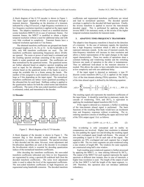
Figure 2: Block diagram of the <strong>G.719</strong> decoder.<br />
Audio signal<br />
Fs = 48 kHz<br />
A block diagram of the decoder is shown in Figure 2. The<br />
transient flag is first decoded which indicates the frame<br />
configuration, i.e. stationary or transient. The spectral envelope<br />
is then decoded and the same, bit-exact, norm adjustment and<br />
bit-allocation algorithms are used at the decoder to re-compute<br />
the bit-allocation which is essential for decoding quantization<br />
indices of the normalized transform coefficients.<br />
After decoding the transform coefficients, the non-coded<br />
transform coefficients (allocated zero bits) in low frequencies<br />
are regenerated by using a spectral-fill codebook built from the<br />
decoded transform coefficients. The noise level adjustment<br />
index is used to adjust the level of the regenerated coefficients.<br />
The non-coded transform coefficients in high frequencies are<br />
regenerated using bandwidth extension. The decoded transform<br />
266<br />
coefficients and regenerated transform coefficients are mixed<br />
and lead to normalized spectrum. The decoded spectral<br />
envelope is applied to the decoded full-band spectrum. Finally,<br />
the inverse transform is applied to recover the time-domain<br />
decoded signal. This is performed by applying either the<br />
inverse MDCT for stationary mode, or the inverse of the higher<br />
temporal resolution transform for transient mode.<br />
3. ADAPTIVE TIME-FREQUENCY TRANSFORM<br />
The adaptive time-frequency transform is based on the detection<br />
of a transient. In the case of stationary signals, the transform<br />
has a high frequency resolution which is able to efficiently<br />
represent stationary sounds. In the case of transient sounds, the<br />
time-frequency transform will increase its time resolution and<br />
allows a better representation of the rapid changes in the input<br />
signal characteristics. These two modes of operations share a<br />
common buffering and windowing module and the switching<br />
between one mode of operation to the other is instantaneous.<br />
Thus no additional look-ahead in the transient detection is<br />
needed. This allows the codec to have selectable time resolution<br />
at low complexity and with zero additional delay.<br />
If the input signal is detected as stationary, a type IV<br />
discrete cosine transform (DCTIV) [2] is applied on the output<br />
~<br />
x ( n)<br />
of the time domain aliasing (TDA) operation. The DCTIV<br />
of the time aliased signal is defined by the following equation:<br />
959<br />
⎡⎛<br />
⎞⎛<br />
⎞ ⎤<br />
=<br />
~<br />
1 1 π<br />
y(<br />
k)<br />
∑ x(<br />
n)<br />
cos⎢⎜<br />
n + ⎟⎜<br />
k + ⎟ ⎥<br />
= ⎣⎝<br />
2 ⎠⎝<br />
2 ⎠ 960<br />
n 0<br />
⎦<br />
, k = 0, 1, …, 959 (1)<br />
The resulting signal y(k) represents the transform coefficients of<br />
the input frame. It should be noted that in stationary mode, the<br />
cascade of windowing, TDA, and DCTIV is equivalent to<br />
applying the modulated lapped transform (MLT) [2].<br />
If the signal is detected as a transient, a further re-ordering<br />
of the time-domain aliased signal is performed. The basis<br />
functions of the resulting filter-bank would have an incoherent<br />
time and frequency responses without re-ordering. The reordering<br />
operation consists of shuffling the upper and lower half<br />
of the TDA output signal<br />
~<br />
x ( n)<br />
as follows:<br />
v( n)<br />
=<br />
~<br />
x(<br />
959 − n)<br />
, n = 0, 1, …, 959. (2)<br />
This re-ordering is only conceptual and in reality no<br />
computations are involved. Higher time resolution is obtained<br />
by zero padding the signal v(n) and dividing the resulting signal<br />
into four overlapped equal length sub-frames. The amount of<br />
zero-padding is equal to 120 on each side of the signal. The<br />
segments are 50% overlapped and each segment has a length<br />
equal to 480. The two inner segments are post-windowed using<br />
a sine window of length 480. The windows for outer segments<br />
are constructed using half a sine window.<br />
Each resulting post-windowed segment is further processed<br />
by applying the MDCT, i.e. time aliasing followed by DCT IV.<br />
The output of the MDCT for each segment represents the signal<br />
spectrum at different time instants, thus in case of transients, a<br />
higher time resolution is used. The length of the output of each<br />
of the four MDCT is half the length of the input segment, i.e.<br />
240. Therefore, this operation does not introduce additional<br />
redundancy.