Athena System Manual - Premio, Inc.
Athena System Manual - Premio, Inc.
Athena System Manual - Premio, Inc.

Create successful ePaper yourself
Turn your PDF publications into a flip-book with our unique Google optimized e-Paper software.
<strong>Athena</strong> <strong>System</strong> <strong>Manual</strong>
ii PREMIO <strong>System</strong> <strong>Manual</strong><br />
Copyright<br />
Disclaimers<br />
PREMIO is a registered trademark of <strong>Premio</strong> Computer, <strong>Inc</strong>. All<br />
other brands and product names are trademarks or registered<br />
trademarks of their respective companies.<br />
© 2002 by <strong>Premio</strong> Computer, <strong>Inc</strong>. All rights reserved.<br />
Version 1.0, March 2002<br />
PREMIO makes no representation or warranties, either expressed<br />
or implied, with respect to the contents of this publication and<br />
specifically disclaims the implied warranties of merchantability<br />
or fitness for a particular purpose. PREMIO shall not be liable for<br />
technical or editorial errors or omissions in this publication, or<br />
for incidental or consequential damages resulting from the<br />
furnishing, performance, or use of this publication. We reserve<br />
the right to revise this publication and to make changes from<br />
time to time in its contents without notification.
iii PREMIO <strong>System</strong> <strong>Manual</strong><br />
Contents<br />
GETTING STARTED...................................................................5<br />
Setting Up ........................................................................6<br />
Connecting Your Keyboard, Mouse, and Speakers ...x<br />
Connecting Your Monitor ..............................................x<br />
Switches and Indicators.................................................8<br />
UPGRADING ............................................................................10<br />
Opening the <strong>System</strong> Unit .............................................11<br />
Closing the <strong>System</strong> Unit ................................................x<br />
Installing an Expansion Card ......................................11<br />
Installing Additional Memory.........................................x<br />
Installing an Additional Hard Disk Drive ....................16<br />
GETTING HELP......................................................................... X<br />
Troubleshooting............................................................18<br />
Monitor Does Not Work ....................................................... x<br />
Keyboard Does Not Work .................................................... x<br />
Mouse Does Not Work ....................................................... 19
iv PREMIO <strong>System</strong> <strong>Manual</strong><br />
<strong>System</strong> Unit Problems .........................................................19<br />
Hard Disk Problems ............................................................20<br />
Warranty Service.......................................................... 20<br />
Technical Support........................................................ 21<br />
PREMIO on the Internet ............................................... 21<br />
APPENDIX ................................................................................22<br />
Limited 3-Year Warranty.............................................. 22<br />
FCC Standards ............................................................. 24<br />
Important Safety Instructions ..................................... 25
Getting Started<br />
Your PREMIO ® <strong>Athena</strong> system typically consists of five main components:<br />
Midtower<br />
Monitor<br />
Speakers<br />
Keyboard<br />
Mouse<br />
Depending on which components you’ve ordered with your <strong>Athena</strong> system, the<br />
components shown in the picture above may vary.
6 PREMIO <strong>System</strong> <strong>Manual</strong><br />
Setting Up<br />
To set up your <strong>Athena</strong> system, simply connect your monitor, mouse, keyboard, and<br />
speakers to the rear of the midtower.<br />
1. Connect the female end of the power cord to the chassis power cord<br />
connector, and then connect the male end of the power cord to your wall<br />
outlet or power strip<br />
2. Connect the keyboard, mouse, speakers (if any) to the back I/O connectors<br />
(see next page for details)<br />
3. Connect your monitor to the video card connector
7 PREMIO <strong>System</strong> <strong>Manual</strong><br />
Connecting Your Keyboard, Mouse, and<br />
Speakers<br />
The picture below is an enlarged view of the back I/O connectors.<br />
The keyboard, mouse, and speakers connectors are color coded for your reference.<br />
Simply connect your keyboard to the purple keyboard connector, and your mouse to<br />
the green mouse connector.<br />
Next, connect your speakers to the light-green connector; this is assuming you are<br />
using the onboard audio. If you have an add-on audio card, please consult the<br />
manual for the location of the speakers connector.
8 PREMIO <strong>System</strong> <strong>Manual</strong><br />
Connecting Your Monitor<br />
The next step is to connect your monitor to your video card. See picture below for the<br />
location of the video card connector.<br />
Once everything is connected, you can now turn on your monitor and system. See the<br />
next page for the location of the midtower’s power switch.
9 PREMIO <strong>System</strong> <strong>Manual</strong><br />
Switches and Indicators<br />
The system unit’s front panel provides access to the CD-ROM, DVD-ROM, or CD-<br />
RW and floppy drives, and to the system’s switches and indicator LEDs.<br />
The CD/DVD/CDRW drive reads information on CDs or DVDs<br />
The floppy disk drive reads and writes data to 3.5” 1.44MB floppy disks<br />
The power switch turns the system on and off<br />
The hard disk drive (HDD) LED lights when the HDD is in use<br />
The power LED lights when the system is on<br />
The reset switch restarts the system in the event of a hardware lockup<br />
The microphone connector allows you to connect a microphone for audio input<br />
The headphone connector allows you to connect a standard headphone<br />
The USB ports allows you to connect USB devices such as printers, digital<br />
cameras, scanners, etc.
10 PREMIO <strong>System</strong> <strong>Manual</strong><br />
Upgrading<br />
You can upgrade your PREMIO system with:<br />
Expansion cards<br />
Additional system memory<br />
Additional hard disk drive<br />
To install an upgrade, you must open the system unit. Before proceeding, read the<br />
important cautionary note below. Then follow the steps on the next page.<br />
Caution! Static discharge can cause permanent damage to internal electronic<br />
components of your computer. Always use the following precautions when working<br />
inside the system unit:<br />
Avoid working in an area with carpeted floor<br />
Touch the back of the midtower’s power supply first<br />
Wear a grounding wrist strap (available at most electronics stores)<br />
when handling electronic components<br />
Do not remove a component from its antistatic packaging until you are<br />
ready to install it
11 PREMIO <strong>System</strong> <strong>Manual</strong><br />
Opening the <strong>System</strong> Unit<br />
Note Opening the system unit could affect your warranty. Check with the dealer<br />
where you purchased your system before opening the system unit.<br />
To open the system unit, you will need a standard philips (the cross head, not the flat<br />
head) screwdriver:<br />
Turn off the system and unplug the power cord from the power cord connector (see<br />
picture below):
12 PREMIO <strong>System</strong> <strong>Manual</strong><br />
Next, using the screwdriver, remove the two screws as shown in the picture below.<br />
Once the two screws are removed, you can simply slide the side cover off by pulling it<br />
towards you.
13 PREMIO <strong>System</strong> <strong>Manual</strong><br />
Closing the <strong>System</strong> Unit<br />
To close the unit, slide the side panel back on and reinstall the two screws.
14 PREMIO <strong>System</strong> <strong>Manual</strong><br />
Installing an Expansion Card<br />
To install an expansion card, open the system unit as described on the previous page.<br />
Next, remove the screw securing the slot bracket cover for the expansion slot you<br />
want to use. Then remove the slot bracket and install your expansion card. Save the<br />
screw to secure the expansion card later. You should also keep the slot bracket, in<br />
case you wish to remove the expansion card later in then future.
15 PREMIO <strong>System</strong> <strong>Manual</strong><br />
Insert the expansion card firmly into the slot, making sure it is seated completely.<br />
Then install the screw onto the expansion card.
16 PREMIO <strong>System</strong> <strong>Manual</strong><br />
Installing Additional Memory<br />
For details on memory configuration, including the placement and type of memory to<br />
use in your system, please refer to the motherboard user’s manual that came with your<br />
system.
17 PREMIO <strong>System</strong> <strong>Manual</strong><br />
Installing an Additional Hard Disk Drive<br />
To install an additional hard disk drive in your system, follow these steps:<br />
Disconnect the hard drive cable and power connector.<br />
Remove the two screws securing the drive bay.<br />
Slide the bay toward the rear of the system unit to remove it.<br />
Insert the new drive into an open position in the bay and secure it with four screws.<br />
Slide the bay back into the system unit and secure it with two screws.<br />
Connect the cables.
18 PREMIO <strong>System</strong> <strong>Manual</strong><br />
Getting Help<br />
Troubleshooting<br />
Your PREMIO system is designed to provide years of trouble-free<br />
performance. If you have a problem with your system, first check the<br />
information in this section for a quick solution.<br />
Monitor Does Not Work<br />
If your monitor appears not to be working properly:<br />
Check that the monitor’s power cable is securely attached to the monitor and<br />
to an outlet that is receiving power.<br />
Check that the monitor’s video cable is securely attached to the monitor and<br />
to the system unit’s video card connector.<br />
Check that the monitor’s power switch is on.<br />
Adjust the monitor’s brightness and contrast controls.<br />
If possible, substitute another monitor that is in good working order. If the<br />
substitute works, your monitor may need repair or replacement.
19 PREMIO <strong>System</strong> <strong>Manual</strong><br />
Keyboard Does Not Work<br />
If the NumLock indicator in the upper right corner of the keyboard does not<br />
light when the system powers up, or the keyboard does not work:<br />
Check that the keyboard cable is securely attached to the system unit’s<br />
keyboard connector.<br />
If possible, substitute another keyboard that is in good working order. If the<br />
substitute works, your keyboard may need replacement.<br />
Mouse Does Not Work<br />
If your mouse pointer does not move or moves erratically when you move<br />
the mouse:<br />
Check that the mouse cable is securely attached to the mouse connector on<br />
the system unit.<br />
Disassemble the mouse and clean the roller ball. (This does not apply if you<br />
have an optical mouse.)
20 PREMIO <strong>System</strong> <strong>Manual</strong><br />
<strong>System</strong> Unit Problems<br />
The fan inside the system unit should make a low, steady sound when operating<br />
properly. If the fan is totally silent:<br />
Check that the system power cord is securely attached to the back of<br />
the system unit and to a power outlet. Verify that the outlet has<br />
power.<br />
If possible, substitute another power cord that is in good working<br />
order. If the substitute works, replace your power cord.<br />
If the fan makes excessive noise:<br />
Turn off the system, open the system unit case, and inspect the fan<br />
for any obstructions.<br />
Turn on the system and listen closely to the fan. If the noise comes<br />
from inside the fan housing, your power supply may need<br />
replacement.<br />
Hard Disk Problems<br />
Your hard disk should make a slight whirring sound when operating properly. If the<br />
disk is totally silent:<br />
Turn off the system, open the system unit case, and check that the<br />
power cable between the power supply and the hard disk is securely<br />
attached at both ends. If it is, your hard disk may be defective.<br />
If the hard disk makes excessive noise:<br />
Turn off the system, open the system unit case, and remove the hard<br />
disk power cable connector from the hard disk. Then turn the<br />
system back on. If the noise disappears, your hard disk may be<br />
defective.<br />
Warranty Service<br />
If you have a problem with your PREMIO system that requires<br />
service during the warranty period, contact the dealer where<br />
you purchased your system. Your dealer will try to resolve the<br />
problem for you. If your dealer cannot resolve the problem, you<br />
can contact PREMIO directly at the address below.<br />
Note To obtain warranty service, you must provide proof of<br />
purchase, including the purchase date.
21 PREMIO <strong>System</strong> <strong>Manual</strong><br />
Technical Support<br />
You can contact PREMIO technical support at the following<br />
address:<br />
<strong>Premio</strong> Computer, <strong>Inc</strong>.<br />
918 Radecki Court<br />
City of Industry, CA 91748<br />
Telephone: 800-568-6388<br />
Fax: 626-839-3191<br />
Email: support@premiopc.com<br />
PREMIO on the Internet<br />
PREMIO maintains a web page on the Internet with the latest<br />
information on PREMIO products, updated drivers, answers to<br />
common problems, an extensive component troubleshooting<br />
guide, and more. Visit our web page at:<br />
http://www.premiopc.com
Appendix<br />
Limited 3-Year Warranty<br />
<strong>Premio</strong> Computer, <strong>Inc</strong>. warrants its line of PREMIO ® computer systems<br />
(hereinafter “Product”) to be free from defects in material and<br />
workmanship for a period of three (3) years from the date of original<br />
purchase from <strong>Premio</strong> Computer, <strong>Inc</strong>. or a <strong>Premio</strong> Computer, <strong>Inc</strong>.<br />
authorized reseller. This warranty does not cover monitor and LCD<br />
panels, nor third-party hardware and software which has a separate<br />
manufacturer’s warranty. Warranty for such third-party hardware and<br />
software, if any, is subject to the third-party’s warranty policy.<br />
PREMIO branded monitors are warranted as follows:<br />
Three (3) year parts and labor except for CRT<br />
One (1) year parts and labor for CRT<br />
PREMIO branded LCD panels are warranted as follows:<br />
One (1) year parts and labor<br />
SERVICE UNDER WARRANTY<br />
If this Product fails to be in good working order during this 3year<br />
warranty period (or specific period of time as noted<br />
above), <strong>Premio</strong> Computer, <strong>Inc</strong>. will, at its option, repair or<br />
replace the Product. Repair parts and/or replacement Products<br />
may be either new or reconditioned at <strong>Premio</strong> Computer <strong>Inc</strong>.’s<br />
discretion. The limited warranty does not include service to<br />
repair damage from improper installation, abuse or<br />
modifications to the Product not approved in writing by <strong>Premio</strong><br />
Computer, <strong>Inc</strong>. Any service repair outside the scope of this<br />
limited warranty shall be at <strong>Premio</strong> Computer, <strong>Inc</strong>.’s or its<br />
Authorized Service Provider’s rates and terms in effect.<br />
This warranty is valid only within the United States and applies only<br />
to Products which are new and in cartons which are unopened on the<br />
date of purchase.<br />
EXCLUSIONS FROM PREMIO, INC. LIMITED<br />
WARRANTY PROGRAM<br />
ALL OTHER EXPRESSED AND IMPLIED WARRANTIES FOR<br />
THIS PRODUCT, INCLUDING THE WARRANTIES OF<br />
MERCHANTABILITY AND FITNESS FOR A PARTICULAR<br />
PURPOSE, ARE HEREBY DISCLAIMED. IF THIS PRODUCT IS<br />
NOT IN GOOD WORKING ORDER AS WARRANTED ABOVE,<br />
PREMIO COMPUTER, INC.'S SOLE AND EXCLUSIVE REMEDY<br />
SHALL BE REPAIR OR REPLACEMENT AS STATED ABOVE.
23 PREMIO <strong>System</strong> <strong>Manual</strong><br />
IN NO EVENT WILL PREMIO COMPUTER, INC. BE LIABLE TO<br />
THE CUSTOMER OR ANY THIRD PARTY FOR ANY<br />
DAMEAGES IN EXCESS OF THE PURCHASE PRICE OF THE<br />
PRODUCT. THIS LIMITATION APPLIES TO DAMAGES OF ANY<br />
KIND INCLUDING ANY DIRECT OR INDIRECT DAMAGES,<br />
LOST PROFITS, LOST SAVINGS OR OTHER SPECIAL,<br />
INCIDENTAL, EXEMPLARY OR CONSEQUENTIAL DAMAGES<br />
WETHER ARISING OUT OF THE USE OF OR INABILITY TO<br />
USE SUCH PRODUCT, EVEN IF PREMIO COMPUTER, INC. OR<br />
AN AUTHORIZED PREMIO COMPUTER, INC.<br />
REPRESENTATIVE OR DEALER HAS BEEN ADVISED OF THE<br />
POSSIBILITY OF SUCH DAMAGES OR OF ANY CLAIM BY<br />
ANY OTHER PARTY. SOME STATES DO NOT ALLOW THE<br />
EXCLUSION OR LIMITATION OF INCIDENTAL OR<br />
CONSEQUENTIAL DAMAGES FOR SOME PRODUCTS, SO THE<br />
ABOVE LIMITATIONS OR EXCLUSIONS MAY NOT APPLY TO<br />
YOU. PREMIO COMPUTER, INC. AUTHORIZED RESELLERS<br />
AND SERVICE PROVIDERS/PARTNERS MAY BE CHANGED,<br />
ADDED OR DELETED, WITHOUT NOTICE OR LIABILITY.<br />
PREMIO COMPUTER, INC. DISCLAIMS ANY AUTHORIZED<br />
RESELLERS AND SERVICE PROVIDER/PARTNER TO THE<br />
PROGRAM. THIS WARRANTY GIVES YOU SPECIFIC LEGAL<br />
RIGHTS AND YOU MAY ALSO HAVE OTHER RIGHTS WHICH<br />
MAY VARY FROM STATE TO STATE.
FCC Standards<br />
The FCC (Federal Communications Commission) restricts the amount of radiation<br />
and radio frequency emissions from computing equipment.<br />
This equipment generates and uses radio frequency energy and if not installed and<br />
used properly in strict accordance with the operation instructions, reference manuals,<br />
and the service manual, may cause interference to radio or television reception.<br />
This equipment can be tested and found to comply with the limits for a Class B digital<br />
device pursuant to part 15 of the FCC rules. There limits are designed to provide<br />
reasonable protection against harmful interference in a residential installation. This<br />
equipment generates, uses, and can radiate radio frequency energy and, if not installed<br />
and used in accordance with the instructions, may cause harmful interference to radio<br />
communications. However, there is no guarantee that interference will not occur in a<br />
particular installation. If this equipment does cause harmful interference to radio or<br />
television reception, which can be determined by turning the equipment off and on,<br />
then the user is encouraged to try to correct the interference by one or more of the<br />
following procedures:<br />
Reorient or relocate the receiving antenna<br />
<strong>Inc</strong>rease the separation between the equipment and receiver<br />
Connect the equipment into an outlet on a circuit different from that<br />
to which the receiver is connected<br />
Consult the dealer or an experienced radio/TV technician for help
25 PREMIO <strong>System</strong> <strong>Manual</strong><br />
Important Safety Instructions<br />
These instructions are provided by Underwriters Laboratories, <strong>Inc</strong>.<br />
1. Read all of these instructions and save them for later reference.<br />
2. Follow all warnings and instructions marked on the product.<br />
3. Unplug this product from the wall outlet before cleaning. Do not<br />
use liquid or aerosol cleaners. Use a damp cloth for cleaning.<br />
4. Do not use this product near water.<br />
5. Do not place this product on an unstable cart, stand or table. The<br />
product may fall, causing serious damage to the product.<br />
6. Slots and openings on the cabinet and the back or bottom are<br />
provided for ventilation. To ensure reliable operation of the<br />
product and to protect it from overheating, do not block or cover<br />
these openings. The openings should never be blocked by placing<br />
the product on a bed, sofa, rug or other similar surface. This<br />
product should never be placed near or over a radiator or heat<br />
register. This product should not be placed in a built-in<br />
installation unless proper ventilation is provided.<br />
7. This product should be operated from the type of power source<br />
indicated on the marking label. If you are not sure of the type of<br />
power available, consult your dealer or local power company.<br />
8. This product is equipped with a 3-wire grounding-type plug, a<br />
plug having a third (grounding) pin. This plug will only fit into a<br />
grounding-type power outlet. This is a safety feature. If you are<br />
unable to insert the plug into the outlet, contact your electrician to<br />
replace your obsolete outlet. Do not defeat the safety purpose of<br />
the grounding-type plug.<br />
9. Do not allow anything to rest on the power cord. Do not locate<br />
this product where the cord will be walked on.<br />
10. If an extension cord is used with this product, make sure that the<br />
total of the ampere ratings on the products plugged into the<br />
extension cord do not exceed the extension cord ampere rating.<br />
Also, make sure that the total of all products plugged into the wall<br />
outlet does not exceed 15 amperes.<br />
11. Never push objects of any kind into this product through cabinet<br />
slots as they may touch dangerous voltage points or short out<br />
parts that could result in a risk of fire or electric shock. Never<br />
spill liquid of any kind on the product.<br />
12. Except as explained elsewhere in this manual, don't attempt to<br />
service this product yourself. Opening and removing those covers<br />
that are marked “Do Not Remove” may expose you to dangerous
voltage points or other risks. Refer all servicing on those<br />
compartments to service personnel.<br />
13. Unplug this product from the wall outlet and refer servicing to<br />
qualified service personnel under the following conditions:<br />
A. When the power cord or plug is damaged or frayed.<br />
B. If liquid has been spilled into the product.<br />
C. If the product has been exposed to rain or water.<br />
D. If the product does not operate normally when the operating<br />
instructions are followed. Adjust only those controls that are<br />
covered by the operating instructions since improper<br />
adjustment of other controls may result in damage and will<br />
often require extensive work by a qualified technician to<br />
restore the product to normal operation.<br />
E. If the product has been dropped or the cabinet has been<br />
damaged.<br />
F. If the product exhibits a distinct change in<br />
performance, indicating a need for service.
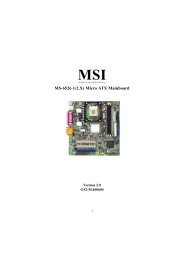
850E Max2<br />
MS-6592 (v1.X) ATX Mainboard<br />
Version 1.0<br />
G52-M6592X1<br />
i
<strong>Manual</strong> Rev: 1.0<br />
Release Date: Nov. 2002<br />
FCC-B Radio Frequency Interference Statement<br />
This equipment has been tested and found to comply with the limits for a class<br />
B digital device, pursuant to part 15 of the FCC rules. These limits are designed<br />
to provide reasonable protection against harmful interference when the equipment<br />
is operated in a commercial environment. This equipment generates, uses<br />
and can radiate radio frequency energy and, if not installed and used in accordance<br />
with the instruction manual, may cause harmful interference to radio<br />
communications. Operation of this equipment in a residential area is likely to<br />
cause harmful interference, in which case the user will be required to correct<br />
the interference at his own expense.<br />
Notice 1<br />
The changes or modifications not expressly approved by the party responsible<br />
for compliance could void the user’s authority to operate the equipment.<br />
Notice 2<br />
Shielded interface cables and A.C. power cord, if any, must be used in order to<br />
comply with the emission limits.<br />
VOIR LA NOTICE D’INSTALLATION AVANT DE RACCORDER AU<br />
RESEAU.<br />
Micro-Star International MS-6592<br />
Tested to comply<br />
with FCC Standard<br />
For Home or Office Use<br />
ii
Copyright Notice<br />
The material in this document is the intellectual property of MICRO-STAR<br />
INTERNATIONAL. We take every care in the preparation of this document,<br />
but no guarantee is given as to the correctness of its contents. Our products<br />
are under continual improvement and we reserve the right to make changes<br />
without notice.<br />
Trademarks<br />
All trademarks are the properties of their respective owners.<br />
AMD, Athlon, Athlon XP, Thoroughbred, and Duron are registered<br />
trademarks of AMD Corporation.<br />
PS/2 and OS ® /2 are registered trademarks of International Business Machines<br />
Corporation.<br />
Windows ® 98/2000/NT/XP are registered trademarks of Microsoft Corporation.<br />
Netware ® is a registered trademark of Novell, <strong>Inc</strong>.<br />
Award ® is a registered trademark of Phoenix Technologies Ltd.<br />
AMI ® is a registered trademark of American Megatrends <strong>Inc</strong>.<br />
Revision History<br />
Revision Revision History Date<br />
V1.0 First release for PCB 1.x<br />
with Intel 850E and ICH4<br />
chipsets<br />
Nov. 2002<br />
Technical Support<br />
If a problem arises with your system and no solution can be obtained from the<br />
user’s manual, please contact your place of purchase or local distributor.<br />
Alternatively, please try the following help resources for further guidance.<br />
Visit the MSI website for FAQ, technical guide, BIOS updates, driver<br />
updates, and other information: http://www.msi.com.tw/<br />
Contact our technical staff at: support@msi.com.tw<br />
iii
Safety Instructions<br />
1. Always read the safety instructions carefully.<br />
2. Keep this User’s <strong>Manual</strong> for future reference.<br />
3. Keep this equipment away from humidity.<br />
4. Lay this equipment on a reliable flat surface before setting it up.<br />
5. The openings on the enclosure are for air convection hence protects the<br />
equipment from overheating. DO NOT COVER THE OPENINGS.<br />
6. Make sure the voltage of the power source and adjust properly 110/220V<br />
before connecting the equipment to the power inlet.<br />
7. Place the power cord such a way that people can not step on it. Do not<br />
place anything over the power cord.<br />
8. Always Unplug the Power Cord before inserting any add-on card or module.<br />
9. All cautions and warnings on the equipment should be noted.<br />
10. Never pour any liquid into the opening that could damage or cause electrical<br />
shock.<br />
11. If any of the following situations arises, get the equipment checked by a<br />
service personnel:<br />
The power cord or plug is damaged.<br />
Liquid has penetrated into the equipment.<br />
The equipment has been exposed to moisture.<br />
The equipment has not work well or you can not get it work according<br />
to User’s <strong>Manual</strong>.<br />
The equipment has dropped and damaged.<br />
The equipment has obvious sign of breakage.<br />
12. DO NOT LEAVE THIS EQUIPMENT IN AN ENVIRONMENT<br />
UNCONDITIONED, STORAGE TEMPERATURE ABOVE 60 0 C (140 0 F), IT<br />
MAY DAMAGE THE EQUIPMENT.<br />
CAUTION: Danger of explosion if battery is incorrectly replaced.<br />
Replace only with the same or equivalent type recommended by the<br />
manufacturer.<br />
iv
CONTENTS<br />
FCC-B Radio Frequency Interference Statement ........................................... ii<br />
Copyright Notice .......................................................................................... iii<br />
Revision History ........................................................................................... iii<br />
Technical Support ......................................................................................... iii<br />
Safety Instructions .......................................................................................iv<br />
Chapter 1. Getting Started ........................................................................ 1-1<br />
Mainboard Specifications .................................................................... 1-2<br />
Mainboard Layout ............................................................................... 1-4<br />
MSI Special Features ........................................................................... 1-5<br />
Fuzzy Logic 4 ............................................................................. 1-5<br />
Live BIOS/Live Driver ............................................................ 1-6<br />
Live Monitor .............................................................................. 1-7<br />
D-Bracket 2 (optional) ................................................................ 1-8<br />
PC Alert 4 ................................................................................. 1-10<br />
MSI DVD 5.1 Channel (optional) ................................................. 1-12<br />
S-Bracket (optional) ..................................................................... 1-14<br />
Chapter 2. Hardware Setup ....................................................................... 2-1<br />
Quick Components Guide .................................................................... 2-2<br />
Central Processing Unit: CPU .............................................................. 2-3<br />
CPU Core Speed Derivation Procedure ......................................... 2-3<br />
CPU Installation Procedures for Socket 478 .................................. 2-4<br />
Installing the CPU Fan .................................................................. 2-5<br />
Memory ................................................................................................ 2-7<br />
Introduction to RIMM Modules ................................................... 2-7<br />
RIMM Modules Combination ....................................................... 2-7<br />
Installing RIMM and C-RIMM Modules ...................................... 2-8<br />
Power Supply ....................................................................................... 2-9<br />
ATX 20-Pin Power Connector: JWR2 ............................................ 2-9<br />
ATX 12V Power Connector: JWR1 ................................................ 2-9<br />
v
Back Panel .......................................................................................... 2-10<br />
Mouse Connector ....................................................................... 2-10<br />
Keyboard Connector ................................................................... 2-11<br />
USB 2.0 Connectors .................................................................... 2-11<br />
Serial Port Connectors: COM A & COM B.................................. 2-12<br />
RJ-45 LAN Jack (optional) ........................................................... 2-12<br />
Parallel Port Connector: LPT1 ...................................................... 2-13<br />
Audio Port Connectors ............................................................... 2-14<br />
Connectors ......................................................................................... 2-15<br />
Floppy Disk Drive Connector: FDD1........................................... 2-15<br />
Fan Power Connectors: CPUFAN1/SYSFAN1/PSFAN1 .............. 2-16<br />
Hard Disk Connectors: IDE1 & IDE2 ........................................... 2-17<br />
Hard Disk RAID Connectors: IDE3, JATA1 & JATA2 ................ 2-18<br />
CD-In Connector: JCD1 ............................................................... 2-20<br />
S-Bracket (SPDIF) Connector: JSP3 (optional) ............................ 2-20<br />
Front Panel Connectors: JFP1 & JFP2 ......................................... 2-22<br />
IEEE 1394 Connector: J1394_1, J1394_2, J1394_3 (optional) ....... 2-23<br />
Front Panel Audio Connector: JAUD1 ........................................ 2-25<br />
Bluetooth Connector: JBT1 (optional) ........................................ 2-26<br />
Front USB Connector: JUSB1 ...................................................... 2-27<br />
D-Bracket 2 Connector: J13 (optional) ......................................... 2-28<br />
IrDA Infrared Module Header: JIR1 ............................................ 2-29<br />
Chassis Intrusion Switch Connector: JCI1 .................................. 2-29<br />
Jumpers .............................................................................................. 2-30<br />
Clear CMOS Jumper: JBAT1 ........................................................ 2-30<br />
Slots ................................................................................................... 2-31<br />
AGP (Accelerated Graphics Port) Slot ......................................... 2-31<br />
PCI (Peripheral Component Interconnect) Slots .......................... 2-31<br />
PCI Interrupt Request Routing .................................................... 2-32<br />
Chapter 3. BIOS Setup .............................................................................. 3-1<br />
Entering Setup...................................................................................... 3-2<br />
vi
Control Keys ................................................................................. 3-2<br />
Getting Help .................................................................................. 3-3<br />
The Main Menu ................................................................................... 3-4<br />
Standard CMOS Features .................................................................... 3-6<br />
Advanced BIOS Features .................................................................... 3-8<br />
Advanced Chipset Features............................................................... 3-12<br />
Integrated Peripherals ........................................................................ 3-15<br />
Power Management Setup ................................................................. 3-19<br />
PNP/PCI Configurations ..................................................................... 3-23<br />
PC Health Status ................................................................................ 3-25<br />
Frequency/Voltage Control ................................................................ 3-26<br />
Load High Performance/BIOS Setup Defaults.................................... 3-28<br />
Set Supervisor/User Password ........................................................... 3-29<br />
Appendix: Using 4- or 6-Channel Audio Function ....................................A-1<br />
Installing C-Media Driver ....................................................................A-2<br />
Hardware Configuration ......................................................................A-3<br />
Software Configuration .......................................................................A-4<br />
Using 4- or 6- Channel Audio Function ............................................ A-13<br />
Troubleshooting ........................................................................................ T-1<br />
Glossary ....................................................................................................G-1<br />
vii
Getting Started<br />
Chapter 1. Getting<br />
Started<br />
Getting Started<br />
Thank you for purchasing the 850E Max2 (MS-6592 v1.X)<br />
ATX mainboard. The 850E Max2 is based on Intel ® 850E North<br />
Bridge & ICH4 South Bridge chipsets for optimal system<br />
efficiency. Designed to fit the advanced Intel ® Pentium 4<br />
processors, 850E Max2 delivers a high performance and professional<br />
desktop platform solution.<br />
1-1
KT3 Ultra2-C ATX Mainboard<br />
MS-6592 ATX Mainboard<br />
1-2<br />
Mainboard Specifications<br />
CPU<br />
Support Intel Pentium ® 4 processor in the 478 pin package<br />
Support up to 3.06GHz or faster<br />
Support Hyper Threading Technology<br />
Chipset<br />
Intel ® 850E chipset<br />
- Support Direct RDRAM up to 2GB maximum memory<br />
- Support <strong>System</strong> bus at 100/133MHz (400/533MHz Data Bus)<br />
Intel ® ICH4 chipset<br />
- AC97 controller integrated<br />
- 2 full IDE channels, up to ATA100<br />
- Low pin count interface for SIO<br />
- USB 2.0 controller<br />
Main Memory<br />
Support two 232-pin 32-bit gold-lead RIMM sockets up to 2GB<br />
Support RIMM 3200 (800MHz) ECC/ 4200 (1066MHz) non-ECC RAMBUS<br />
memory<br />
Slots<br />
One AGP (Accelerated Graphics Port) slot<br />
Six 32-bit/33MHz Master PCI bus slots<br />
On-Board IDE<br />
An IDE controller on the ICH4 chipset provides IDE HDD/CD-ROM with<br />
PIO, Bus Master and Ultra DMA100 operation modes<br />
Can connect up to four IDE devices<br />
On-Board Peripherals<br />
On-Board Peripherals include:<br />
- 1 floppy port supports 2 FDDs with 360K, 720K, 1.2M, 1.44M and<br />
2.88Mbytes<br />
- 2 serial ports (COM A + COM B)<br />
- 1 parallel port supports SPP/EPP/ECP mode<br />
- 6 USB 2.0 ports (Rear * 4/ Front * 2)<br />
- 1 D-Bracket 2 pin header
- 3 audio ports in vertical<br />
Getting Started<br />
Serial ATA Interface (Optional)<br />
Support PROMISE 20376 controller chip with two serial ATA (150MB/s)<br />
and one ATA133<br />
Support RAID 0 or 1 by up to 2 or 3 parallel ATA or serial ATA connectors<br />
Audio<br />
Support C-Media CMI8738/PCI-6ch audio<br />
6CH DAC for AC3 ® 5.1CH purpose<br />
HRTF-based 3D positional audio, supporting DirectSound 3D and A3D<br />
interface<br />
Support 4.1/5.1 speakers, C3DX positional audio in 4/6CH speaker mode<br />
Legacy audio SBPRO compatible<br />
DLS-based wavetable music synthesizer<br />
Network (Optional)<br />
Support Intel 82540EM Gigabit LAN or 82562EZ 10/100 LAN<br />
IEEE1394 (Optional)<br />
Support 3 ports (via external bracket) with transfer rate up to 400 Mbps<br />
BIOS<br />
The mainboard BIOS provides “Plug & Play” BIOS which detects the peripheral<br />
devices and expansion cards of the board automatically.<br />
IDE drive auto configure, Advanced Power Management (APM) 1.2, ACPI<br />
1.0, DMI 2.0, ECC/Parity support, LS120 support, audo enables onboard<br />
SCSI termintor<br />
Dimension<br />
ATX Form Factor: 30.5 cm (L) x 24.4 cm (W) x 4 layers PCB<br />
Mounting<br />
9 mounting holes<br />
Others<br />
Suspend to RAM/Disk (S3/S4)<br />
PC2001 compliant<br />
1-3
KT3 Ultra2-C ATX Mainboard<br />
MS-6592 ATX Mainboard<br />
1-4<br />
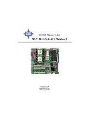
Top : mouse<br />
Bottom: keyboard<br />
USB<br />
ports<br />
Top : Parallel Port<br />
Bottom:<br />
COM A<br />
COM B<br />
T: LAN ja ck<br />
B: USB Ports<br />
Line-Out<br />
Line-In<br />
Mic<br />
JSP3<br />
J13<br />
JCD1<br />
Intel<br />
RC82540EM<br />
CMI8738<br />
JCI1<br />
JWR1<br />
Winbond<br />
W83627HF-AW<br />
JAUD1<br />
Mainboard Layout<br />
JBT1<br />
PCI Slot 6<br />
JIR1<br />
PCI Slot 1<br />
PCI Slot 2<br />
PCI Slot 3<br />
PCI Slot 4<br />
PCI Slot 5<br />
AGP Slot<br />
JUSB1<br />
BIOS<br />
ICH4<br />
JBAT1<br />
850E Max2 (MS-6592 v1.X) ATX Mainboard<br />
CPUFAN1<br />
RIMM2<br />
VIA<br />
VT6306<br />
RIMM1<br />
J1394_1 J1394_2 J1394_3<br />
JATA2<br />
ATX<br />
Power Supply<br />
IDE 3<br />
PROMISE<br />
PDC20376<br />
PSFAN1<br />
IDE 2<br />
SYSFAN1<br />
BATT<br />
+<br />
JATA1<br />
JFP1<br />
JFP2<br />
FDD1<br />
IDE 1
Fuzzy Logic 4<br />
MSI Special Features<br />
Getting Started<br />
The Fuzzy Logic 4 utility is a user friendly tool that allows users to<br />
view and adjust the current system status. To overclock the CPU FSB (Front<br />
Side Bus) frequency under the Windows operating system, click FSB and use<br />
the right and left arrow keys to select the desired FSB, and then click Apply to<br />
apply the new setup value. To enable the system running at the specified FSB<br />
every time when you click Turbo, click Save to save the desired FSB first. If<br />
you want to know the maximal CPU overclocking value, click Auto to start<br />
testing. The CPU FSB will automatically increase the testing value until the PC<br />
reboots. After rebooting, click Turbo to apply the test result. Click Default to<br />
restore the default values.<br />
Features:<br />
MSI Logo links to the MSI Web site<br />
CPU Speed allows users to adjust the CPU speed through CPU<br />
Multiplier and FSB<br />
Voltage allows user to adjust the voltage of CPU/Memory/AGP<br />
MSI Info provides information about the mainboard, BIOS and OS<br />
CPU Info provides detailed information about the CPU<br />
CPU Fan Speed shows the current running speed of CPU Fan<br />
CPU Temp. shows the current CPU temperature<br />
MSI Reminds You...<br />
To adjust the options under CPU Speed and Voltage, use the right<br />
and left arrow keys to select the desired value and then click Apply<br />
to run the setup value.<br />
1-5
KT3 Ultra2-C ATX Mainboard<br />
MS-6592 ATX Mainboard<br />
Live BIOS/Live Driver<br />
The Live BIOS/Live Driver is a tool used to detect and<br />
update your BIOS/drivers online so that you don’t need to search<br />
for the correct BIOS/driver version throughout the Web site. To<br />
use the function, you need to install the “MSI Live Update 2”<br />
application. After the installation, the “MSI Live Update 2” icon<br />
(as shown on the right) will appear on the screen.<br />
Double click the “MSI Live Update 2” icon, and the following<br />
screen will appear:<br />
Five buttons are placed on the leftmost pane of the screen. Click the desired<br />
button to start the update process.<br />
Live BIOS – Updates the BIOS online.<br />
Live Driver – Updates the drivers online.<br />
Live VGA BIOS – Updates the VGA BIOS online.<br />
Live VGA Driver – Updates the VGA driver online.<br />
Live Utility – Updates the utilities online.<br />
If the product you purchased does not support any of the functions listed<br />
above, a “sorry” message is displayed. For more information on the update<br />
instructions, insert the companion CD and refer to the “Live Update Guide”<br />
under the “<strong>Manual</strong>” Tab.<br />
1-6
Live Monitor<br />
The Live Monitor is a tool used to schedule the search<br />
for the latest BIOS/drivers version on the MSI Web site. To use<br />
the function, you need to install the “MSI Live Update 2”<br />
application. After the installation, the “MSI Live Monitor” icon<br />
(as shown on the right) will appear on the screen. Double click<br />
this icon to run the application.<br />
Getting Started<br />
Double click the “MSI Live Monitor” icon at the lower-right corner<br />
of the taskbar, and the following dialog box will appear. You can specify how<br />
often the system will automatically search for the BIOS/drivers version, or<br />
change the LAN settings right from the dialog box.<br />
You can right-click the MSI Live Monitor icon to perform the functions<br />
listed below:<br />
Auto Search – Searches for the BIOS/drivers version you need immediately.<br />
View Last Result – Allows you to view the last search result if there is any.<br />
Preference – Configures the Search function, including the Search schedule.<br />
Exit – Exits the Live Monitor application.<br />
FAQ – Provides a link to a database which contents various possible questions<br />
about MSI's products for users to inquire.<br />
1-7
KT3 Ultra2-C ATX Mainboard<br />
MS-6592 ATX Mainboard<br />
D-Bracket 2 (Optional)<br />
D-Bracket 2 is a USB bracket integrating four Diagnostic LEDs, which<br />
use graphic signal display to help users understand their system. The LEDs<br />
provide up to 16 combinations of signals to debug the system. The 4 LEDs can<br />
detect all problems that fail the system, such as VGA, RAM or other failures.<br />
This special feature is very useful for overclocking users. These users can use<br />
the feature to detect if there are any problems or failures. D-Bracket 2 supports<br />
both USB 1.1 & 2.0 spec.<br />
1-8<br />
D-Bracket 2 for mainboard with bluetooth<br />
connector (1 port)<br />
1 2<br />
D-Bracket 2 for mainboard without<br />
bluetooth connector (2 ports)<br />
D-Bracket 2 Description<br />
<strong>System</strong> Power ON<br />
3 4<br />
- The D-LED will hang here if the processor is damaged or<br />
not installed properly.<br />
Early Chipset Initialization<br />
Memory Detection Test<br />
- Testing onboard memory size. The D-LED will hang if the<br />
memory module is damaged or not installed properly.<br />
Decompressing BIOS image to RAM for fast booting.<br />
Initializing Keyboard Controller.<br />
Testing VGA BIOS<br />
- This will start writing VGA sign-on message to the screen.
Getting Started<br />
To better protect the CPU from overheating, a new feature, COOLER<br />
XP, has been added to decrease the temperature of AMD Athlon XP CPU. To<br />
do so, simply click COOLER XP and the screen will show the Cute skin (as<br />
shown below) with information about the CPU and chipset. Right-click the<br />
mouse to select the skin you want to switch to.<br />
Cute<br />
MSI Reminds You...<br />
The new feature COOLER XP will work only if your mainboard<br />
supports AMD Athlon XP CPU.<br />
Items shown on PC Alert 4 vary depending on your system’s status.<br />
1-11
KT3 Ultra2-C ATX Mainboard<br />
MS-6592 ATX Mainboard<br />
MSI DVD 5.1 Channel (Optional)<br />
The motherboard comes with MSI DVD application which supports 5.1<br />
channel (6-channel audio) operation. The accompanying MSI DVD is a convenient<br />
tool to meet increasing demands for home entertainment.<br />
1-12<br />
Note: MSI DVD supports Dolby Digital format only. To view DTSformatted<br />
video, you should convert it to Dolby Digital format first.<br />
To play DVD with 6-channel audio output, you must configure both the<br />
MSI DVD application and the audio codec’s software utility. Otherwise, the 6channel<br />
audio function will not work properly. For information on how to<br />
select 6-channel mode in the audio software utility, refer to Appendix. Using 4or<br />
6-Channel Audio Function.<br />
Follow the procedures below to enable 6-channel support with MSI DVD:<br />
1. Click on this button from the control panel of MSI DVD.<br />
2. Click the Audio tab.<br />
3. Select 6 speaker mode (5.1 channel).
Getting Started<br />
4. Click OK.<br />
For more information about MSI DVD, you can refer to the online help<br />
coming with the application.<br />
To enter the online help:<br />
1. Click on the icon at the bottom-right corner of the control panel.<br />
2. The following window appears.<br />
Click here<br />
3. Click MSIDVD FAQ.<br />
1-13
KT3 Ultra2-C ATX Mainboard<br />
MS-6592 ATX Mainboard<br />
S-Bracket (Optional)<br />
S-Bracket is a bracket which provides 2 SPDIF jacks for digital audio<br />
transmission and 2 analog Line-Out connectors for additional 4-channel analog<br />
audio output. With the S-Bracket, your system will be able to perform 6channel<br />
audio operation for wonderful surround sound effect, or connect to<br />
Sony & Philips Digital Interface (SPDIF) speakers for audio transmission with<br />
better quality.<br />
The S-Bracket offers two types of SPDIF connectors: one for optical<br />
fiber and the other for coaxial connection. Select the appropriate one to meet<br />
your own need. For more information on S-Bracket, refer to Appendix. Using<br />
4- or 6-Channel Audio Function.<br />
1-14<br />
S-Bracket<br />
CEN/SUB RL/RR<br />
SPDIF jack (optical) SPDIF jack (coaxial) Analog Line-Out jacks
Hardware Setup<br />
Chapter 2. Hardware<br />
Setup<br />
Hardware Setup<br />
This chapter tells you how to install the CPU, memory<br />
modules, and expansion cards, as well as how to setup the jumpers<br />
on the mainboard. Also, it provides the instructions on connecting<br />
the peripheral devices, such as the mouse, keyboard,<br />
etc.<br />
While doing the installation, be careful in holding the<br />
components and follow the installation procedures.<br />
2-1
KT3 MS-6592 Ultra2-C ATX ATX Mainboard<br />
Back Panel I/O,<br />
p.2-10<br />
JCD1, p.2-20<br />
JCI1, p.2-29<br />
JIR1, p.2-29<br />
JSP3, p.2-20<br />
2-2<br />
J13, p.2-28<br />
Quick Components Guide<br />
JWR1, p.2-9<br />
JAUD1,<br />
p.2-25<br />
JUSB1,<br />
p.2-27<br />
JBT1, p.2-26<br />
CPU, p.2-3<br />
CPUFAN1, p.2-16<br />
J1394_1,<br />
J1394_2,<br />
J1394_3,<br />
p.2-23<br />
JFP1, p.2-22<br />
RIMMs, p.2-7<br />
JWR2, p.2-9<br />
PSFAN1, p.2-16<br />
FDD1, p.2-15<br />
AGP Slot, p.2-31<br />
IDE1 & IDE2,<br />
p.2-17<br />
SYSFAN1, p.2-16<br />
PCI Slots, p.2-31<br />
JBAT1, p.2-30<br />
IDE3, p.2-18<br />
JATA1 & JATA2,<br />
p.2-18<br />
JFP2, p.2-22
Central Processing Unit: CPU<br />
Hardware Setup<br />
The mainboard supports Intel ® Pentium ® 4 processor in the 478 pin<br />
package. The mainboard uses a CPU socket called PGA478 for easy CPU<br />
installation. When you are installing the CPU, make sure the CPU has a<br />
heat sink and a cooling fan attached on the top to prevent overheating. If<br />
you do not find the heat sink and cooling fan, contact your dealer to purchase<br />
and install them before turning on the computer.<br />
CPU Core Speed Derivation Procedure<br />
CPU Clock multiplied by Core/Bus ratio equals the CPU core speed.<br />
For example:<br />
If CPU Clock = 100MHz<br />
Core/Bus ratio = 14<br />
then CPU core speed = Host Clock x Core/Bus ratio<br />
= 100MHz x 14<br />
= 1.4 GHz<br />
MSI Reminds You...<br />
Overheating<br />
Overheating will seriously damage the CPU and system, always<br />
make sure the cooling fan can work properly to protect<br />
the CPU from overheating.<br />
Replacing the CPU<br />
While replacing the CPU, always turn off the ATX power supply<br />
or unplug the power supply’s power cord from grounded<br />
outlet first to ensure the safety of CPU.<br />
Overclocking<br />
This motherboard is designed to support overclocking.<br />
However, please make sure your components are able to tolerate<br />
such abnormal setting, while doing overclocking. Any attempt<br />
to operate beyond product specifications is not<br />
recommended. We do not guarantee the damages or risks<br />
caused by inadequate operation or beyond product<br />
specifications.<br />
2-3
KT3 MS-6592 Ultra2-C ATX ATX Mainboard<br />
CPU Installation Procedures for Socket 478<br />
1. Please turn off the power and<br />
unplug the power cord before<br />
installing the CPU.<br />
2. Pull the lever sideways away<br />
from the socket. Make sure<br />
to raise the lever up to a 90degree<br />
angle.<br />
3. Look for the cut edge. The cut<br />
edge should point towards the<br />
lever pivot. The CPU can only<br />
fit in the correct orientation.<br />
4. If the CPU is correctly<br />
installed, the pins should be<br />
completely embedded into the<br />
socket and can not be seen.<br />
Please note that any violation<br />
of the correct installation<br />
procedures may cause<br />
permanent damages to your<br />
mainboard.<br />
5. Press the CPU down firmly<br />
into the socket and close the<br />
lever. As the CPU is likely to<br />
move while the lever is being<br />
closed, always close the lever<br />
with your fingers pressing<br />
tightly on top of the CPU to<br />
make sure the CPU is<br />
properly and completely<br />
embedded into the socket.<br />
2-4<br />
Sliding<br />
Plate<br />
Dot / Cut edge<br />
Dot / Cut edge<br />
Dot / Cut edge<br />
Press down<br />
the CPU<br />
Open Lever<br />
90 degree<br />
Correct CPU placement<br />
O<br />
X<br />
<strong>Inc</strong>orrect CPU placement<br />
Close<br />
Lever
Hardware Setup<br />
Installing the CPU Fan<br />
As processor technology pushes to faster speeds and higher performance,<br />
thermal management becomes increasingly important. To dissipate heat, you<br />
need to attach the CPU cooling fan and heatsink on top of the CPU. Follow<br />
the instructions below to install the Heatsink/Fan:<br />
1. Locate the CPU and its retention<br />
mechanism on the motherboard.<br />
retention mechanism<br />
3. Mount the fan on top of the heatsink.<br />
Press down the fan until its four clips<br />
get wedged in the holes of the retention<br />
mechanism.<br />
2. Position the heatsink onto the retention<br />
mechanism.<br />
4. Press the two levers down to fasten<br />
the fan. Each lever can be pressed<br />
down in only ONE direction.<br />
levers<br />
2-5
KT3 MS-6592 Ultra2-C ATX ATX Mainboard<br />
5. Connect the fan power cable from the mounted fan to the 3-pin fan power connector<br />
on the board.<br />
2-6<br />
NOTES<br />
fan power cable
Memory<br />
Hardware Setup<br />
The mainboard provides 2 gold-lead sockets for 232-pin RIMM modules.<br />
To operate properly, modules must be installed in pairs. You can install either<br />
one RIMM and one C-RIMM or two RIMMs. If only one RIMM slot is<br />
populated, you must install one C-RIMM (Continuity RIMM) module on the<br />
other unused RIMM slot. A C-RIMM module is a dummy module for continuing<br />
the signal connection. The mainboard supports the memory size up to<br />
2 GB.<br />
RIMM Modules Combination<br />
RIMM2 & RIMM1<br />
(from left to right)<br />
Introduction to RIMM Modules<br />
RIMM module is a module integrated with RDRAM chips. It is similar<br />
to a DIMM package but uses different pin settings. Rambus trademarked<br />
the term RIMM as an entire word for a module using Rambus technology.<br />
You can install the RIMM modules in the following combination:<br />
Slot RIMM1 RIMM2 Total Memory<br />
Option 1 128MB, 256MB<br />
512MB, 1GB<br />
C-RIMM (0MB) 128MB~1GB<br />
Option 2 128MB, 256MB 128MB, 256MB 256MB~2GB<br />
512MB, 1GB 512MB, 1GB<br />
2-7
KT3 MS-6592 Ultra2-C ATX ATX Mainboard<br />
Installing RIMM and C-RIMM Modules<br />
1. The RIMM slot has 2 Notch Keys, so the RIMM memory module can only<br />
fit in one orientation.<br />
2. Insert the RIMM memory module vertically into the RIMM slot. Then<br />
push it in.<br />
3. The plastic clips at sides of the RIMM slot will automatically close.<br />
2-8<br />
NOTCH<br />
RIMM Module<br />
4. You may insert another RIMM module or a C-RIMM module (as shown<br />
below) in the unused slot to ensure the system’s proper operation.<br />
C-RIMM Module
Power Supply<br />
Hardware Setup<br />
The mainboard supports ATX power supply for the power system. Before<br />
inserting the power supply connector, always make sure that all components<br />
are installed properly to ensure that no damage will be caused.<br />
ATX 20-Pin Power Connector: JWR2<br />
This connector allows you to connect to an ATX power supply. To<br />
connect to the ATX power supply, make sure the plug of the power supply is<br />
inserted in the proper orientation and the pins are aligned. Then push down<br />
the power supply firmly into the connector.<br />
ATX 12V Power Connector: JWR1<br />
This 12V power connector is used to provide power to the CPU.<br />
2<br />
4<br />
JWR1<br />
1<br />
3<br />
JWR1 Pin Definition<br />
PIN SIGNAL<br />
1 GND<br />
2 GND<br />
3 12V<br />
4 12V<br />
JWR2 Pin Definition<br />
PIN SIGNAL<br />
1 3.3V<br />
2 3.3V<br />
3 GND<br />
4 5V<br />
5 GND<br />
6 5V<br />
7 GND<br />
8 PW_OK<br />
9 5V_SB<br />
10 12V<br />
11<br />
1<br />
20 10<br />
JWR2<br />
PIN SIGNAL<br />
11 3.3V<br />
12 -12V<br />
13 GND<br />
14 PS_ON<br />
15 GND<br />
16 GND<br />
17 GND<br />
18 -5V<br />
19 5V<br />
20 5V<br />
2-9
KT3 MS-6592 Ultra2-C ATX ATX Mainboard<br />
Mouse<br />
2-10<br />
Back Panel<br />
The back panel provides the following connectors:<br />
Mouse Connector<br />
The mainboard provides a standard PS/2 ® mouse mini DIN connector<br />
for attaching a PS/2 ® mouse. You can plug a PS/2 ® mouse directly into this<br />
connector. The connector location and pin assignments are as follows:<br />
4<br />
6<br />
USB Ports<br />
2 1<br />
PS/2 Mouse (6-pin Female)<br />
5<br />
3<br />
Parallel<br />
Pin Definition<br />
LAN<br />
(Optional)<br />
Keyboard COM A COM B USB Ports L-in<br />
PIN SIGNAL DESCRIPTION<br />
1 Mouse DATA Mouse DATA<br />
2 NC No connection<br />
3 GND Ground<br />
4 VCC +5V<br />
5 Mouse Clock Mouse clock<br />
6 NC No connection<br />
MIC<br />
L-out
Hardware Setup<br />
Keyboard Connector<br />
The mainboard provides a standard PS/2 ® keyboard mini DIN connector<br />
for attaching a PS/2 ® keyboard. You can plug a PS/2 ® keyboard directly<br />
into this connector.<br />
4<br />
6<br />
2 1<br />
PS/2 Keyboard (6-pin Female)<br />
5<br />
3<br />
Pin Definition<br />
PIN SIGNAL DESCRIPTION<br />
1 Keyboard DATA Keyboard DATA<br />
2 NC No connection<br />
3 GND Ground<br />
4 VCC +5V<br />
5 Keyboard Clock Keyboard clock<br />
6 NC No connection<br />
USB 2.0 Connectors<br />
The mainboard provides a UHCI (Universal Host Controller Interface)<br />
Universal Serial Bus root for attaching USB devices such as keyboard, mouse<br />
or other USB-compatible devices. You can plug the USB device directly into<br />
the connector.<br />
1 2 3 4<br />
5 6 7 8<br />
USB Ports<br />
USB Port Description<br />
PIN SIGNAL DESCRIPTION<br />
1 VCC +5V<br />
2 -Data 0 Negative Data Channel 0<br />
3 +Data0 Positive Data Channel 0<br />
4 GND Ground<br />
5 VCC +5V<br />
6 -Data 1 Negative Data Channel 1<br />
7 +Data 1 Positive Data Channel 1<br />
8 GND Ground<br />
2-11
KT3 MS-6592 Ultra2-C ATX ATX Mainboard<br />
Serial Port Connectors: COM A & COM B<br />
The mainboard offers two 9-pin male DIN connectors as serial port COM<br />
A & COM B. The ports are 16550A high speed communication ports that<br />
send/receive 16 bytes FIFOs. You can attach a serial mouse or other serial<br />
devices directly to the connectors.<br />
6 7 8 9<br />
9-Pin Male DIN Connector<br />
2-12<br />
1 2 3 4 5<br />
Pin Definition<br />
PIN SIGNAL DESCRIPTION<br />
1 DCD Data Carry Detect<br />
2 SIN Serial In or Receive Data<br />
3 SOUT Serial Out or Transmit Data<br />
4 DTR Data Terminal Ready)<br />
5 GND Ground<br />
6 DSR Data Set Ready<br />
7 RTS Request To Send<br />
8 CTS Clear To Send<br />
9 RI Ring Indicate<br />
RJ-45 LAN Jack (Optional)<br />
The mainboard provides one standard RJ-45 jack for connection to Local<br />
Area Network (LAN). You can connect a network cable to the LAN jack.<br />
RJ-45 LAN Jack<br />
Pin Definition<br />
PIN SIGNAL DESCRIPTION<br />
1 TDP Transmit Differential Pair<br />
2 TDN Transmit Differential Pair<br />
3 RDP Receive Differential Pair<br />
4 NC Not Used<br />
5 NC Not Used<br />
6 RDN Receive Differential Pair<br />
7 NC Not Used<br />
8 NC Not Used
Hardware Setup<br />
Parallel Port Connector: LPT1<br />
The mainboard provides a 25-pin female centronic connector as LPT.<br />
A parallel port is a standard printer port that supports Enhanced Parallel Port<br />
(EPP) and Extended Capabilities Parallel Port (ECP) mode.<br />
13 1<br />
25<br />
Pin Definition<br />
PIN SIGNAL DESCRIPTION<br />
1 STROBE Strobe<br />
2 DATA0 Data0<br />
3 DATA1 Data1<br />
4 DATA2 Data2<br />
5 DATA3 Data3<br />
6 DATA4 Data4<br />
7 DATA5 Data5<br />
8 DATA6 Data6<br />
9 DATA7 Data7<br />
10 ACK# Acknowledge<br />
11 BUSY Busy<br />
12 PE Paper End<br />
13 SELECT Select<br />
14 AUTO FEED# Automatic Feed<br />
15 ERR# Error<br />
16 INIT# Initialize Printer<br />
17 SLIN# Select In<br />
18 GND Ground<br />
19 GND Ground<br />
20 GND Ground<br />
21 GND Ground<br />
22 GND Ground<br />
23 GND Ground<br />
24 GND Ground<br />
25 GND Ground<br />
14<br />
2-13
KT3 MS-6592 Ultra2-C ATX ATX Mainboard<br />
Audio Port Connectors<br />
Line Out is a connector for Speakers or Headphones. Line In is used<br />
for external CD player, Tape player, or other audio devices. Mic is a connector<br />
for microphones.<br />
2-14<br />
1/8” Stereo Audio Connectors<br />
MIC<br />
Line In<br />
Line Out<br />
MSI Reminds You...<br />
For advanced audio application, CMedia 8738MX is provided<br />
to offer support for 6-channel audio operation and can turn<br />
rear audio connectors from 2-channel to 4-/6-channel audio.<br />
For more information on 6-channel audio operation, please<br />
refer to Appendix. Using 4- or 6-Channel Audio Function.
Connectors<br />
Hardware Setup<br />
The mainboard provides connectors to connect to FDD, IDE HDD, case,<br />
modem, LAN, USB Ports, IR module and CPU/<strong>System</strong>/Power Supply FAN.<br />
Floppy Disk Drive Connector: FDD1<br />
The mainboard provides a standard floppy disk drive connector that<br />
supports 360K, 720K, 1.2M, 1.44M and 2.88M floppy disk types.<br />
FDD1<br />
2-15
KT3 MS-6592 Ultra2-C ATX ATX Mainboard<br />
Fan Power Connectors: CPUFAN1/SYSFAN1/PSFAN1<br />
The CPUFAN1 (processor fan), SYSFAN1 (system fan) and PSFAN1<br />
(power fan) support system cooling fan with +12V. It supports three-pin head<br />
connector. When connecting the wire to the connectors, always take note that<br />
the red wire is the positive and should be connected to the +12V, the black<br />
wire is Ground and should be connected to GND. If the mainboard has a<br />
<strong>System</strong> Hardware Monitor chipset on-board, you must use a specially designed<br />
fan with speed sensor to take advantage of the CPU fan control.<br />
2-16<br />
SENSOR<br />
+12V<br />
GND<br />
CPUFAN1<br />
SENSOR<br />
+12V<br />
GND<br />
PSFAN1<br />
SYSFAN1<br />
GND<br />
+12V<br />
SENSOR<br />
MSI Reminds You...<br />
Always consult the vendors for proper CPU cooling fan.
Hardware Setup<br />
Hard Disk Connectors: IDE1 & IDE2<br />
The mainboard has a 32-bit Enhanced PCI IDE and Ultra DMA 66/100/<br />
133 controller that provides PIO mode 0~4, Bus Master, and Ultra DMA 66/<br />
100/133 function. You can connect up to four hard disk drives, CD-ROM,<br />
120MB Floppy (reserved for future BIOS) and other devices.<br />
IDE2<br />
IDE1<br />
IDE1 (Primary IDE Connector)<br />
The first hard drive should always be connected to IDE1. IDE1 can<br />
connect a Master and a Slave drive. You must configure second hard<br />
drive to Slave mode by setting the jumper accordingly.<br />
IDE2 (Secondary IDE Connector)<br />
IDE2 can also connect a Master and a Slave drive.<br />
MSI Reminds You...<br />
If you install two hard disks on cable, you must configure the<br />
second drive to Slave mode by setting its jumper. Refer to the<br />
hard disk documentation supplied by hard disk vendors for jumper<br />
setting instructions.<br />
2-17
KT3 MS-6592 Ultra2-C ATX ATX Mainboard<br />
Hard Disk RAID Connectors: IDE3, JATA1 & JATA2<br />
The mainboard has 3 IDE RAID connectors, which are controlled by<br />
Promise 20376.<br />
IDE3 is a 32-bit Enhanced PCI IDE and Ultra DMA 66/100/133 controller<br />
that provides PIO mode 0~5, Bus Master, and Ultra DMA 66/100/133<br />
function. You can connect up to 2 hard disk drives, CD-ROM, 120MB Floppy<br />
(reserved for future BIOS) and other devices.<br />
The mainboard also provides two optional dual high-speed Serial ATA<br />
interface ports, JATA1 & JATA2. Each supports 1 st generation serial ATA<br />
data rates of 150 MB/s. Both connectors are fully compliant with Serial ATA<br />
1.0 specifications. Each Serial ATA connector can connect to 1 hard disk<br />
device. Please refer to Serial ATA Raid manual for detail software installation<br />
procedure.<br />
2-18<br />
1<br />
7<br />
JATA2<br />
1<br />
7<br />
JATA1<br />
IDE3
Optional Serial ATA cable<br />
JATA1 & JATA2 Pin Definition<br />
PIN SIGNAL PIN SIGNAL<br />
1 GND 2 TXP<br />
3 TXN 4 GND<br />
5 RXN 6 RXP<br />
7 GND<br />
Connect to JATA1 or JATA2<br />
Hardware Setup<br />
Take out the dust cover and<br />
connect to the hard disk<br />
devices<br />
MSI Reminds You...<br />
Please do not fold the serial ATA cable in a 90-degree angle,<br />
which will cause the loss of data during the transmission.<br />
2-19
KT3 MS-6592 Ultra2-C ATX ATX Mainboard<br />
CD-In Connector: JCD1<br />
The connector is for CD-ROM audio connector.<br />
S-Bracket (SPDIF) Connector: JSP3 (Optional)<br />
The connector allows you to connect a S-Bracket for Sony & Philips<br />
Digital Interface (SPDIF). The S-Bracket offers 2 SPDIF jacks for digital<br />
audio transmission (one for optical fiber connection and the other for coaxial),<br />
and 2 analog Line-Out jacks for 4-channel audio output.<br />
To attach the fiber-optic cable to optical SPDIF jack, you need to remove<br />
the plug from the jack first. The two SPDIF jacks support SPDIF output<br />
only.<br />
2-20<br />
11<br />
12<br />
JCD1<br />
JSP3<br />
R<br />
GND<br />
L<br />
1<br />
2<br />
JSP3 Pin Definition<br />
PIN SIGNAL DESCRIPTION PIN SIGNAL DESCRIPTION<br />
1 VCC5 VCC 5V 2 VDD3 VDD 3.3V<br />
3 SPDFO S/PDIF output 4 (No Pin) Key<br />
5 GND Ground 6 SPDFI S/PDIF input<br />
7 LFE-OUT Audio bass output 8 SOUT-R Audio right surrounding output<br />
9 CET-OUT Audio center output 10 SOUT-L Audio left surrounding output<br />
11 GND Ground 12 GND Ground
Connect to JSP3<br />
Optional S-Bracket<br />
CEN/SUB RL/RR<br />
Hardware Setup<br />
SPDIFJack (optical) SPDIF Jack (coaxial) Analog Line-Out Jacks<br />
2-21
KT3 MS-6592 Ultra2-C ATX ATX Mainboard<br />
Front Panel Connectors: JFP1 & JFP2<br />
The mainboard provides two front panel connectors for electrical connection<br />
to the front panel switches and LEDs. JFP1 is compliant with Intel ®<br />
Front Panel I/O Connectivity Design Guide.<br />
2-22<br />
JFP1 Pin Definition<br />
PIN SIGNAL DESCRIPTION<br />
1 HD_LED_P Hard disk LED pull-up<br />
2 FP PWR/SLP MSG LED pull-up<br />
3 HD_LED_N Hard disk active LED<br />
4 FP PWR/SLP MSG LED pull-up<br />
5 RST_SW_N Reset Switch low reference pull-down to GND<br />
6 PWR_SW_P Power Switch high reference pull-up<br />
7 RST_SW_P Reset Switch high reference pull-up<br />
8 PWR_SW_N Power Switch low reference pull-down to GND<br />
9 RSVD_DNU Reserved. Do not use.<br />
JFP2 Pin Definition<br />
Speaker<br />
PIN SIGNAL PIN SIGNAL<br />
1 GND 2 SPK-<br />
3 SLED 4 BUZ+<br />
5 PLED 6 BUZ-<br />
7 NC 8 SPK+<br />
Power<br />
LED<br />
2<br />
1<br />
8 7<br />
HDD<br />
LED<br />
2 1<br />
JFP2<br />
Power<br />
Switch<br />
Reset<br />
Switch<br />
JFP1<br />
Power<br />
LED<br />
10<br />
9
Hardware Setup<br />
IEEE 1394 Connectors: J1394_1, J1394_2, J1394_3 (Optional)<br />
The mainboard provides three 1394 pin headers that allow you to connect<br />
optional IEEE 1394 ports.<br />
9<br />
10<br />
J1394_1<br />
1<br />
2<br />
9<br />
10<br />
J1394_2<br />
1<br />
2<br />
PIN SIGNAL<br />
1 TPA+<br />
3 Ground<br />
5 TPB+<br />
7 Cable power<br />
9 Key (no pin)<br />
J1394_3<br />
Pin Definition<br />
PIN SIGNAL<br />
2 TPA-<br />
4 Ground<br />
6 TPB-<br />
8 Cable power<br />
10 Ground<br />
MSI Reminds You...<br />
Please note that the following installation procedures are for your<br />
reference only. The actual layout of the IEEE1394 connectors<br />
may look slight different from the pictures shown below.<br />
9<br />
10<br />
1<br />
2<br />
2-23
KT3 MS-6592 Ultra2-C ATX ATX Mainboard<br />
How to attach the IEEE 1394 Bracket: Foolproof<br />
design<br />
1. Take out the<br />
IEEE 1394<br />
Bracket.<br />
2-24<br />
2. Locate the IEEE1394<br />
connectors (J1394_1,<br />
J1394_2 & J1394_3) on the<br />
mainboard.<br />
3. Connect the cables of the<br />
IEEE 1394 Bracket to the<br />
connectors. Align the<br />
foolproof design with the<br />
connectors to avoid misinserting.<br />
4. Place the IEEE 1394 Bracket<br />
into the first slot of your<br />
system case.
Hardware Setup<br />
Front Panel Audio Connector: JAUD1<br />
The JAUD1 front panel audio connector allows you to connect to the<br />
front panel audio and is compliant with Intel ® Front Panel I/O Connectivity<br />
Design Guide.<br />
2<br />
1<br />
JAUD1<br />
10<br />
9<br />
JAUD1 Pin Definition<br />
PIN SIGNAL DESCRIPTION<br />
1 AUD_MIC Front panel microphone input signal<br />
2 AUD_GND Ground used by analog audio circuits<br />
3 AUD_MIC_BIAS Microphone power<br />
4 AUD_VCC Filtered +5V used by analog audio circuits<br />
5 AUD_FPOUT_R Right channel audio signal to front panel<br />
6 AUD_RET_R Right channel audio signal return from front panel<br />
7 HP_ON Reserved for future use to control headphone amplifier<br />
8 KEY No pin<br />
9 AUD_FPOUT_L Left channel audio signal to front panel<br />
10 AUD_RET_L Left channel audio signal return from front panel<br />
MSI Reminds You...<br />
If you don’t want to connect to the front audio<br />
header, pins 5 & 6, 9 & 10 have to be jumpered in<br />
order to have signal output directed to the rear<br />
audio ports. Otherwise, the Line-Out connector on<br />
the back panel will not function.<br />
6 10<br />
5<br />
9<br />
2-25
KT3 MS-6592 Ultra2-C ATX ATX Mainboard<br />
Bluetooth Connector: JBT1 (Optional)<br />
This connector is used to connect a bluetooth module for wireless<br />
connection.<br />
2-26<br />
2<br />
1<br />
JBT1<br />
8<br />
7<br />
JBT1 Pin Definition<br />
PIN SIGNAL PIN SIGNAL<br />
1 5VDUAL 2 3VDUAL<br />
3 D+ (USB signal) 4 GND<br />
5 D- (USB signal) 6 GND<br />
7 GND 8 NC<br />
MSI Reminds You...<br />
Because the bluetooth connector shares the USB interface with<br />
blue-colored USB2.0 connector, one of the USB2.0 port (see instruction<br />
on the cable) will not function when you attach a<br />
bluetooth module to this connector.
Hardware Setup<br />
Front USB Connectors: JUSB1<br />
The mainboard provides one USB 2.0 pin headers JUSB1 that is<br />
compliant with Intel ® I/O Connectivity Design Guide. USB 2.0 technology<br />
increases data transfer rate up to a maximum throughput of 480Mbps, which<br />
is 40 times faster than USB 1.1, and is ideal for connecting high-speed USB<br />
interface peripherals such as USB HDD, digital cameras, MP3 players,<br />
printers, modems and the like.<br />
2 10<br />
1 9<br />
JUSB1<br />
(USB 2.0/Intel spec)<br />
JUSB1 Pin Definition<br />
PIN SIGNAL PIN SIGNAL<br />
1 VCC 2 VCC<br />
3 USB0- 4 USB1-<br />
5 USB0+ 6 USB1+<br />
7 GND 8 GND<br />
9 Key 10 USBOC<br />
2-27
KT3 MS-6592 Ultra2-C ATX ATX Mainboard<br />
D-Bracket 2 Connector: J13 (Optional)<br />
The mainboard comes with a J13 connector for you to connect to D-<br />
Bracket 2. D-Bracket 2 is a USB Bracket that supports both USB1.1 & 2.<br />
0 spec. It integrates four LEDs and allows users to identify system problem<br />
through 16 various combinations of LED signals. For definitions of 16 signal<br />
combinations, please refer to D-Bracket 2 in Chapter 1.<br />
2-28<br />
J13 Pin Definition<br />
Pin Signal<br />
1 DBG1 (high for green color)<br />
2 DBR1 (high for red color)<br />
3 DBG2 (high for green color)<br />
4 DBR2 (high for red color)<br />
5 DBG3 (high for green color)<br />
6 DBR3 (high for red color)<br />
7 DBG4 (high for green color)<br />
8 DBR4 (high for red color)<br />
9 Key<br />
10 NC<br />
2 10<br />
1 9<br />
J13<br />
Connected to J13<br />
Connected to JUSB1<br />
D-Bracket 2 (optional)<br />
LEDs
Hardware Setup<br />
IrDA Infrared Module Header: JIR1<br />
The connector allows you to connect to IrDA Infrared module. You<br />
must configure the setting through the BIOS setup to use the IR function.<br />
JIR1 is compliant with Intel ® Front Panel I/O Connectivity Design Guide.<br />
Pin Signal<br />
1 NC<br />
2 NC<br />
3 VCC5<br />
4 GND<br />
5 IRTX<br />
6 IRRX<br />
5<br />
6<br />
JIR1<br />
1<br />
2<br />
Chassis Intrusion Switch Connector: JCI1<br />
This connector is connected to a 2-pin chassis switch. If the chassis is<br />
opened, the switch will be short connected. The system will record this status<br />
and show a warning message on the screen. To clear the warning, you must<br />
enter the BIOS utility and clear the record. JCI1 is compliant with Intel ®<br />
Front Panel I/O Connectivity Design Guide.<br />
CINTRU 1<br />
GND 2<br />
JCI1<br />
2-29
KT3 MS-6592 Ultra2-C ATX ATX Mainboard<br />
The motherboard provides the following jumpers for you to set the<br />
computer’s function. This section will explain how to change your<br />
motherboard’s function through the use of jumpers.<br />
Clear CMOS Jumper: JBAT1<br />
There is a CMOS RAM on board that has a power supply from external<br />
battery to keep the data of system configuration. With the CMOS RAM, the<br />
system can automatically boot OS every time it is turned on. If you want to<br />
clear the system configuration, use the JBAT1 (Clear CMOS Jumper ) to clear<br />
data. Follow the instructions below to clear the data:<br />
2-30<br />
1<br />
Clear CMOS<br />
Jumpers<br />
JBAT1<br />
MSI Reminds You...<br />
You can clear CMOS by shorting 2-3 pin while the system is off.<br />
Then return to 1-2 pin position. Avoid clearing the CMOS while<br />
the system is on; it will damage the mainboard.<br />
1<br />
Keep CMOS<br />
1
Slots<br />
Hardware Setup<br />
The motherboard provides one AGP slot and six 32-bit PCI bus slots.<br />
AGP Slot<br />
PCI Slots<br />
AGP (Accelerated Graphics Port) Slot<br />
The AGP slot allows you to insert the AGP graphics card. AGP is an<br />
interface specification designed for the throughput demands of 3D graphics.<br />
It introduces a 66MHz, 32-bit channel for the graphics controller to directly<br />
access main memory. The mainboard supports 4x/8x 1.5V AGP card.<br />
PCI (Peripheral Component Interconnect) Slots<br />
The PCI slots allow you to insert the expansion cards to meet your needs.<br />
When adding or removing expansion cards, make sure that you unplug the<br />
power supply first. Meanwhile, read the documentation for the expansion card<br />
to make any necessary hardware or software settings for the expansion card,<br />
such as jumpers, switches or BIOS configuration.<br />
2-31
KT3 MS-6592 Ultra2-C ATX ATX Mainboard<br />
PCI Interrupt Request Routing<br />
The IRQ, acronym of interrupt request line and pronounced I-R-Q, are<br />
hardware lines over which devices can send interrupt signals to the<br />
microprocessor. The PCI IRQ pins are typically connected to the PCI bus INT<br />
A# ~ INT D# pins as follows:<br />
Order 1 Order 2 Order 3 Order 4<br />
PCI Slot 1 INT B# INT C# INT D# INT A#<br />
PCI Slot 2 INT A# INT B# INT C# INT D#<br />
PCI Slot 3 INT B# INT C# INT D# INT A#<br />
PCI Slot 4 INT C# INT D# INT A# INT B#<br />
PCI Slot 5 INT D# INT A# INT B# INT C#<br />
PCI Slot 6 INT A# INT B# INT C# INT D#<br />
2-32
BIOS Setup<br />
Chapter 3. BIOS Setup<br />
BIOS Setup<br />
This chapter provides information on the BIOS Setup program<br />
and allows you to configure the system for optimum use.<br />
You may need to run the Setup program when:<br />
An error message appears on the screen during the system<br />
booting up, and requests you to run SETUP.<br />
You want to change the default settings for customized<br />
features.<br />
3-1
MS-6592 ATX Mainboard<br />
3-2<br />
Entering Setup<br />
Power on the computer and the system will start POST (Power On Self Test)<br />
process. When the message below appears on the screen, press key to<br />
enter Setup.<br />
Press DEL to enter SETUP<br />
If the message disappears before you respond and you still wish to enter Setup,<br />
restart the system by turning it OFF and On or pressing the RESET button.<br />
You may also restart the system by simultaneously pressing , ,<br />
and keys.<br />
Control Keys<br />
Move to the previous item<br />
Move to the next item<br />
Move to the item in the left hand<br />
Move to the item in the right hand<br />
Select the item<br />
Jumps to the Exit menu or returns to the main menu from a submenu<br />
<strong>Inc</strong>rease the numeric value or make changes<br />
Decrease the numeric value or make changes<br />
General help, only for Status Page Setup Menu and Option Page<br />
Setup Menu<br />
Restore the previous CMOS value from CMOS, only for Option Page<br />
Setup Menu<br />
Load the default CMOS value from Fail-Safe default table, only for<br />
Option Page Setup Menu<br />
Load Optimized defaults<br />
Save all the CMOS changes and exit
Getting Help<br />
BIOS Setup<br />
After entering the Setup menu, the first menu you will see is the Main Menu.<br />
Main Menu<br />
The main menu lists the setup functions you can make changes to. You can<br />
use the control keys ( ↑↓ ) to select the item. The on-line description of the<br />
highlighted setup function is displayed at the bottom of the screen.<br />
Sub-Menu<br />
If you find a right pointer symbol (as shown<br />
in the right view) appears to the left of certain<br />
fields that means a sub-menu containing 8IDE Primary Master<br />
additional options can be launched from this 8IDE Primary Slave<br />
field. You can use control keys ( ↑↓ ) to 8IDE Secondary Master<br />
highlight the field and press to call<br />
8IDE Secondary Slave<br />
up the sub-menu. Then you can use the control<br />
keys to enter values and move from field<br />
to field within a sub-menu. If you want to<br />
return to the main menu, just press .<br />
General Help <br />
The BIOS setup program provides a General Help screen. You can call up<br />
this screen from any menu by simply pressing . The Help screen lists the<br />
appropriate keys to use and the possible selections for the highlighted item.<br />
Press to exit the Help screen.<br />
MSI Reminds You...<br />
The items under each BIOS category described in this chapter<br />
are under continuous update for better system performance.<br />
Therefore, the description may be slightly different from the latest<br />
BIOS and should be held for reference only.<br />
3-3
MS-6592 ATX Mainboard<br />
3-4<br />
The Main Menu<br />
Once you enter Phoenix-Award BIOS CMOS Setup Utility, the Main Menu<br />
(Figure 1) will appear on the screen. The Main Menu allows you to select<br />
from twelve setup functions and two exit choices. Use arrow keys to select<br />
among the items and press to accept or enter the sub-menu.<br />
Standard CMOS Features<br />
Use this menu for basic system configurations, such as time, date etc.<br />
Advanced BIOS Features<br />
Use this menu to setup the items of special enhanced features.<br />
Advanced Chipset Features<br />
Use this menu to change the values in the chipset registers and optimize your<br />
system’s performance.<br />
Integrated Peripherals<br />
Use this menu to specify your settings for integrated peripherals.<br />
Power Management Setup<br />
Use this menu to specify your settings for power management.<br />
PNP/PCI Configurations<br />
This entry appears if your system supports PnP/PCI.
PC Health Status<br />
This entry shows your PC health status.<br />
Frequency/Voltage Control<br />
Use this menu to specify your settings for frequency/voltage control.<br />
BIOS Setup<br />
Load High Performance Defaults<br />
Use this menu to load factory default settings into the BIOS for stable system<br />
performance operations.<br />
Load BIOS Setup Defaults<br />
Use this menu to load the BIOS values for the best system performance, but<br />
the system stability may be affected.<br />
Set Supervisor Password<br />
Use this menu to set Supervisor Password.<br />
Set User Password<br />
Use this menu to set User Password.<br />
Save & Exit Setup<br />
Save changes to CMOS and exit setup.<br />
Exit Without Saving<br />
Abandon all changes and exit setup.<br />
3-5
MS-6592 ATX Mainboard<br />
3-6<br />
Standard CMOS Features<br />
The items in Standard CMOS Features Menu are divided into 11 categories.<br />
Each category includes no, one or more than one setup items. Use the arrow<br />
keys to highlight the item and then use the or keys to select<br />
the value you want in each item.<br />
Date<br />
The date format is .<br />
day Day of the week, from Sun to Sat. (Read only)<br />
month The month from Jan. through Dec.<br />
date The date from 1 to 31 can be keyed by numeric function keys.<br />
year The year can be adjusted by users.<br />
Time<br />
The time format is .<br />
IDE Primary/Secondary Master/Slave<br />
Press PgUp/ or PgDn/ to select <strong>Manual</strong>, None or Auto type. Note that<br />
the specifications of your drive must match with the drive table. The hard<br />
disk will not work properly if you enter improper information for this category.<br />
If your hard disk drive type is not matched or listed, you can use <strong>Manual</strong> to<br />
define your own drive type manually.<br />
If you select <strong>Manual</strong>, related information is asked to be entered to the follow
BIOS Setup<br />
ing items. Enter the information directly from the keyboard. This information<br />
should be provided in the documentation from your hard disk vendor or<br />
the system manufacturer.<br />
Access Mode The settings are CHS, LBA, Large, Auto.<br />
Capacity The formatted size of the storage device.<br />
Cylinder Number of cylinders.<br />
Head Number of heads.<br />
Precomp Write precompensation.<br />
Landing Zone Cylinder location of the landing zone.<br />
Sector Number of sectors.<br />
Drive A/B<br />
This item allows you to set the type of floppy drives installed. Available<br />
options: None, 360K, 5.25 in., 1.2M, 5.25 in., 720K, 3.5 in., 1.44M, 3.5 in., 2.<br />
88M, 3.5 in.<br />
Video<br />
The setting controls the type of video adapter used for the primary monitor of<br />
the system. Available options: EGA/VGA , CGA 40, CGA 80, MONO.<br />
Halt On<br />
The setting determines whether the system will stop if an error is detected at<br />
boot. Available options are:<br />
All Errors The system stops when any error is detected.<br />
No Errors The system doesn’t stop for any detected error.<br />
All, But Keyboard The system doesn’t stop for a keyboard error.<br />
All, But Diskette The system doesn’t stop for a disk error.<br />
All, But Disk/Key The system doesn’t stop for either a disk or a<br />
keyboard error.<br />
Base/Extended/Total Memory<br />
The three items show the memory status of your system (read only).<br />
3-7
MS-6592 ATX Mainboard<br />
3-8<br />
Advanced BIOS Features<br />
Virus Protection<br />
The item is to set the Virus Warning feature for IDE Hard Disk boot sector<br />
protection. If the function is enabled and any attempt to write data into this<br />
area is made, BIOS will display a warning message on screen and beep.<br />
Settings: Disabled, Enabled.<br />
CPU L1 & L2 Cache<br />
The item allows you to turn on or off CPU’s internal (L1) and external (L2)<br />
cache. Settings: Enabled, Disabled.<br />
MSI Reminds You...<br />
Enabling the functionality of Hyper-Threading Technology for<br />
your computer system requires ALL of the following platform<br />
Components:<br />
*CPU: An Intel ® Pentium ® 4 Processor with HT Technology;<br />
*Chipset: An Intel ® Chipset that supports HT Technology;<br />
*BIOS: A BIOS that supports HT Technology and has it enabled;<br />
and<br />
*OS: An operating system that supports HT Technology.<br />
For more information on Hyper-threading Technology, go to:<br />
www.intel.com/info/hyperthreading
BIOS Setup<br />
CPU Hyper-Threading<br />
The processor uses Hyper-Threading technology to increase transaction<br />
rates and reduces end-user response times. The technology treats the two<br />
cores inside the processor as two logical processors that can execute<br />
instructions simultaneously. In this way, the system performance is highly<br />
improved. If you disable the function, the processor will use only one core<br />
to execute the instructions. Settings: Enabled, Disabled.<br />
Fast Boot<br />
The option speeds up Power On Self Test (POST) after you power on the<br />
computer. When setting the item to Enabled, BIOS will shorten or skip some<br />
check items during POST. Settings: Enabled, Disabled.<br />
1st/2nd/3rd Boot Device<br />
The items allow you to set the sequence of boot devices where BIOS attempts<br />
to load the disk operating system. The settings are:<br />
Floppy The system will boot from floppy drive.<br />
LS120 The system will boot from LS-120 drive.<br />
HDD-0 The system will boot from the first HDD.<br />
SCSI The system will boot from the SCSI.<br />
CDROM The system will boot from the CD-ROM.<br />
HDD-1 The system will boot from the second HDD.<br />
HDD-2 The system will boot from the third HDD.<br />
HDD-3 The system will boot from the fourth HDD.<br />
ZIP100 The system will boot from ATAPI ZIP drive.<br />
USB-FDD The system will boot from USB-interfaced floppy drive.<br />
USB-ZIP The system will boot from any USB-interfaced ZIP drive.<br />
USB-CDROM The system will boot from the USB-interfaced CD-ROM.<br />
USB-HDD The system will boot from the USB-interfaced HDD.<br />
LAN The system will boot from the Network drive.<br />
Disabled Disable this sequence.<br />
MSI Reminds You...<br />
1. Available settings for “1st/2nd/3rd Boot Device” vary depending<br />
on the bootable devices you have installed. For<br />
example, if you did not install a floppy drive, the setting “Floppy”<br />
does not show up.<br />
2. If you want to boot from any of the USB-interfaced devices,<br />
please set USB Legacy Support to All Device.<br />
3-9
MS-6592 ATX Mainboard<br />
Boot Other Device<br />
Setting the option to Enabled allows the system to try to boot from other<br />
device if the system fails to boot from the 1st/2nd/3rd boot device.<br />
Swap Floppy<br />
Setting to Enabled will swap floppy drives A: and B:.<br />
Seek Floppy<br />
Setting to Enabled will make BIOS seek floppy drive A: before booting the<br />
system. Settings: Disabled, Enabled.<br />
Boot Up Num-Lock LED<br />
This setting is to set the Num Lock status when the system is powered on.<br />
Setting to On will turn on the Num Lock key when the system is powered on.<br />
Setting to Off will allow users to use the arrow keys on the numeric keypad.<br />
Setting options: On, Off.<br />
Typematic Rate Setting<br />
This item is used to enable or disable the typematic rate setting including<br />
Typematic Rate & Typematic Delay.<br />
3-10<br />
Typematic Rate (Chars/Sec)<br />
After Typematic Rate Setting is enabled, this item allows you to set the<br />
rate (characters/second) at which the keys are accelerated. Settings: 6, 8,<br />
10, 12, 15, 20, 24, 30.<br />
Typematic Delay (Msec)<br />
This item allows you to select the delay between when the key was first<br />
pressed and when the acceleration begins. Settings: 250, 500, 750 and<br />
1000.Typematic Delay (Msec)<br />
This item allows you to select the delay between when the key was first<br />
pressed and when the acceleration begins. Settings: 250, 500, 750 and<br />
1000.<br />
Security Option<br />
This specifies the type of BIOS password protection that is implemented. Settings<br />
are described below:
BIOS Setup<br />
Option Description<br />
Setup The password prompt appears only when end users try to<br />
run Setup.<br />
<strong>System</strong> A password prompt appears every time when the computer<br />
is powered on or when end users try to run Setup.<br />
APIC Mode<br />
This field is used to enable or disable the APIC (Advanced Programmable<br />
Interrupt Controller). Due to compliance to PC2001 design guide, the system<br />
is able to run in APIC mode. Enabling APIC mode will expand available<br />
IRQs resources for the system. Settings: Enabled, Disabled.<br />
MPS Version Control For OS<br />
This field allows you to select which MPS (Multi-Processor Specification)<br />
version to be used for the operating system. You need to select the MPS<br />
version supported by your operating system. To find out which version to<br />
use, consult the vendor of your operating system. Settings: 1.4, 1.1.<br />
Boot OS/2 for DRAM > 64MB<br />
This allows you to run the OS/2 ® operating system with DRAM greater than<br />
64MB. Setting options: No, Yes.<br />
Hard Disk S.M.A.R.T.<br />
This allows you to activate the S.M.A.R.T. (Self-Monitoring Analysis & Reporting<br />
Technology) capability for the hard disks. S.M.A.R.T is a utility that<br />
monitors your disk status to predict hard disk failure. This gives you an opportunity<br />
to move data from a hard disk that is going to fail to a safe place<br />
before the hard disk becomes offline. Settings: Enabled and Disabled.<br />
Full Screen LOGO Show<br />
This item enables you to show the company logo on the bootup screen. Settings<br />
are:<br />
Enabled Shows a still image (logo) on the full screen at boot.<br />
Disabled Shows the POST messages at boot.<br />
3-11
MS-6592 ATX Mainboard<br />
Small Logo (EPA) Show<br />
This item enables you to show the EPA logo (brand specific graphics) on<br />
the bootup screen. Settings are:<br />
Disabled Shows the normal POST screen at boot.<br />
Enabled Shows a still image (EPA logo) on the screen at<br />
boot.<br />
3-12
Advanced Chipset Features<br />
BIOS Setup<br />
MSI Reminds You...<br />
Change these settings only if you are familiar with the chipset.<br />
RDRAM Bus Frequency<br />
Use this item to configure the bus frequency of the installed RDRAMs. Setting<br />
options: Auto, 300MHz, 400MHz, 533MHz.<br />
DRAM Data Integrity Mode<br />
Select ECC (Error-Checking & Correcting Code) or Non-ECC according to<br />
the type of DRAM installed.<br />
<strong>System</strong> BIOS Cacheable<br />
Selecting Enabled allows caching of the system BIOS ROM at F0000h-<br />
FFFFFh, resulting in better system performance. However, if any program<br />
writes to this memory area, a system error may result. Setting options: Enabled,<br />
Disabled.<br />
Video BIOS Cacheable<br />
Selecting Enabled allows caching of the video BIOS ROM at C0000h to<br />
C7FFFh, resulting in better video performance. However, if any program writes<br />
to this memory area, a system error may result. Setting options: Disabled,<br />
Enabled.<br />
3-13
MS-6592 ATX Mainboard<br />
Video RAM Cacheable<br />
Selecting Enabled allows caching of the video memory (RAM) at A0000h<br />
to AFFFFh, resulting in better video performance. However, if any program<br />
writes to this memory area, a memory access error may result. Setting<br />
options: Disabled, Enabled.<br />
Delayed Transaction<br />
The chipset has an embedded 32-bit posted write buffer to support delayed<br />
transactions cycles so that transactions to and from the ISA bus are buffered<br />
and PCI bus can perform other transactions while the ISA transaction is<br />
underway. Select Enabled to support compliance with PCI specification version<br />
2.1. Setting options: Enabled, Disabled.<br />
AGP Aperture Size (MB)<br />
This setting controls just how much system RAM can be allocated to AGP for<br />
video purposes. The aperture is a portion of the PCI memory address range<br />
dedicated to graphics memory address space. Host cycles that hit the aperture<br />
range are forwarded to the AGP without any translation. The option allows<br />
the selection of an aperture size of 4MB, 8MB, 16MB, 32MB, 64MB, 128MB,<br />
and 256 MB.<br />
Delay Prior to Thermal<br />
When the CPU temperature reaches a factory preset level, a thermal monitoring<br />
mechanism will be enabled following the appropriate timing delay specified<br />
in this field. With the thermal monitoring enabled, clock modulation controlled<br />
by the processor’s internal thermal sensor is also activated to keep the<br />
processor within allowable temperature limit. Setting options: 4 Min, 8 Min,<br />
16 Min, 32 Min.<br />
3-14
Integrated Peripherals<br />
BIOS Setup<br />
On-Chip Primary/Secondary PCI IDE<br />
The integrated peripheral controller contains an IDE interface with support<br />
for two IDE channels. Choose Enabled to activate each channel separately.<br />
IDE Primary/Secondary Master/Slave PIO<br />
The four IDE PIO (Programmed Input/Output) fields let you set a PIO mode<br />
(0-4) for each of the four IDE devices that the onboard IDE interface supports.<br />
Modes 0 through 4 provide successively increased performance. In Auto mode,<br />
the system automatically determines the best mode for each device. The settings<br />
are: Auto, Mode 0, Mode 1, Mode 2, Mode 3, Mode 4.<br />
IDE Primary/Secondary Master/Slave UDMA<br />
Ultra DMA/33/66/100 implementation is possible only if your IDE hard drive<br />
supports it and the operating environment includes a DMA driver (Windows<br />
3-15
MS-6592 ATX Mainboard<br />
95 OSR2 or a third-party IDE bus master driver). If your hard drive and your<br />
system software both support Ultra DMA/33, Ultra DMA/66 or even Ultra<br />
DMA/100, select Auto to enable BIOS support. Settings: Auto, Disabled.<br />
USB Controller<br />
Select Enabled if your system contains a Universal Serial Bus (USB) controller<br />
and you have USB peripherals. Settings: Enabled, Disabled.<br />
USB Keyboard/Mouse Support<br />
Set to Enabled if your need to use a USB keyboard/mouse in the operating<br />
system that does not support or have any USB driver installed, such as DOS<br />
and SCO Unix.<br />
LAN Selection<br />
The field determines whether the onboard LAN controller is activated. Setting<br />
options: Enabled, Disabled.<br />
Serial ATA Selection<br />
The field determines whether the onboard Serial ATA controller is activated.<br />
Setting options: Enabled, Disabled.<br />
Onboard Sound Chip<br />
The field determines whether the onboard audio controller is activated. Setting<br />
options: Enabled, Disabled.<br />
Onboard 1394 Selection<br />
The field determines whether the onboard IEEE1394 controller is activated.<br />
Setting options: Enabled, Disabled.<br />
IDE HDD Block Mode<br />
Block mode is also called block transfer, multiple commands, or multiple<br />
sector read/write. If your IDE hard drive supports block mode (most new<br />
drives do), select Enabled for automatic detection of the optimal number of<br />
block read/writes per sector the drive can support. Settings: Enabled, Disabled.<br />
POWER ON Function<br />
This controls how the PS/2 mouse or keyboard can power on the system.<br />
Available settings are: Password, Hot KEY, BUTTON ONLY, Keyboard 98.<br />
3-16
BIOS Setup<br />
KB Power ON Password<br />
If POWER ON Function is set to Password, then you can set a password in the<br />
field for the PS/2 keyboard to power on the system.<br />
Hot Key Power ON<br />
If POWER ON Function is set to Hot KEY, you can assign a hot key<br />
combination in the field for the PS/2 keyboard to power on the system. Settings:<br />
Ctrl-F1 through Ctrl-F12.<br />
Onboard FDC Controller<br />
The item is used to enable or disable the onboard Floppy controller. Select<br />
Enabled when you have installed a floppy disk drive and want to use it.<br />
Onboard Serial Port 1/2<br />
The items specify the base I/O port address and IRQ for the onboard Serial<br />
Port 1 (COM A)/Serial Port 2 (COM B). Selecting Auto allows BIOS to automatically<br />
determine the correct base I/O port address. Settings: Disabled,<br />
3F8/IRQ4, 2F8/IRQ3, 3E8/IRQ4, 2E8/IRQ3, Auto.<br />
UART Mode Select<br />
This setting allows you to specify the operation mode for serial port 2. Setting<br />
options: IrDA, ASKIR, Normal.<br />
IrDA IrDA-compliant Serial Infrared Port<br />
ASKIR Amplitude Shift Keyed Infrared Port<br />
Normal RS-232C Serial Port<br />
RxD, TxD Active<br />
This setting controls the receiving and transmitting speed of the IR peripheral<br />
in use. Setting options: Hi,Hi, Hi,Lo, Lo,Hi, Lo,Lo.<br />
IR Transmission Delay<br />
This setting determines whether the IR transmission rate will be delayed while<br />
converting to receiving mode. Setting options: Disabled, Enabled.<br />
IR Duplex Mode<br />
This setting controls the operating mode of IR transmission/reception. Setting<br />
options: Full, Half. Under Full Duplex mode, synchronous, bi-directional<br />
transmission/reception is allowed. Under Half Duplex mode, only<br />
asynchronous, bi-directional transmission/reception is allowed.<br />
3-17
MS-6592 ATX Mainboard<br />
Use IR Pins<br />
Please consult your IR peripheral documentation to select the correct setting<br />
of the TxD and RxD signals. Setting options: RxD2,TxD2, IR-Rx2Tx2.<br />
Onboard Parallel Port<br />
This specifies the I/O port address and IRQ of the onboard parallel port.<br />
Settings: 378/IRQ7, 278/IRQ5, 3BC/IRQ7, Disabled.<br />
Parallel Port Mode<br />
This item selects the operating mode for the parallel port: SPP, EPP, ECP, or<br />
ECP+EPP, Normal.<br />
SPP: Standard Parallel Port<br />
EPP: Enhanced Parallel Port<br />
ECP: Extended Capability Port<br />
ECP + EPP: Extended Capability Port + Enhanced Parallel<br />
Port<br />
EPP Mode Select<br />
The onboard parallel port is EPP Spec. compliant, so after the user chooses<br />
the onboard parallel port with the EPP function, the setting “EPP Version”<br />
should be set. At this time either 1.7 spec or 1.9 spec can be chosen.<br />
ECP Mode Use DMA<br />
The ECP mode has to use the DMA channel, so after the user chooses the<br />
onboard parallel port with the ECP feature, the setting “ECP Mode User DMA”<br />
should be set. At this time, the user can choose between DMA channel 3 or 1.<br />
PWRON After PWF-Fail<br />
This item specifies whether your system will reboot after a power failure or<br />
interrupt occurs. Available settings are:<br />
Off Leaves the computer in the power off state<br />
On Leaves the computer in the power on state<br />
Former-Sts Restores the system to the status before power failure<br />
or interrupt occurred.<br />
3-18
Power Management Setup<br />
BIOS Setup<br />
MSI Reminds You...<br />
S3-related functions described in this section are available only<br />
when your BIOS supports S3 sleep mode.<br />
IPCA Function<br />
This item is to activate the ACPI (Advanced Configuration and Power Management<br />
Interface) Function. If your operating system is ACPI-aware, such<br />
as Windows ® 98SE/2000/ME, select Enabled. Settings: Enabled, Disabled.<br />
ACPI Standby State<br />
This item specifies the power saving modes for ACPI function. Options are:<br />
S1/POS The S1 sleep mode is a low power state. In this state, no<br />
system context is lost (CPU or chipset) and hardware<br />
maintains all system context.<br />
S3/STR The S3 sleep mode is a lower power state where the information<br />
of system configuration and open applications/<br />
3-19
MS-6592 ATX Mainboard<br />
3-20<br />
files is saved to main memory that remains powered<br />
while most other hardware components turn off to save<br />
energy. The information stored in memory will be used<br />
to restore the system when a “wake up” event occurs.<br />
Run VGABIOS if S3 Resume<br />
Selecting Enabled allows BIOS to call VGA BIOS to initialize the VGA card<br />
when system wakes up (resumes) from S3 sleep state. The system resume<br />
time is shortened when you disable the function, but system will need an AGP<br />
driver to initialize the VGA card. Therefore, if the AGP driver of the card<br />
does not support the initialization feature, the display may work abnormally<br />
or not function after resuming from S3.<br />
Power Management/APM<br />
This item is used to select the degree (or type) of power saving and is<br />
related to the mode: Suspend Time Out. There are three options for power<br />
management:<br />
Min Saving Minimum Power Management. Suspend Time Out =<br />
1 Hour.<br />
Max Saving Maximum Power Management. Suspend Time Out =<br />
1 Min.<br />
User Define Allows end users to configure the Suspend Time Out<br />
field.<br />
Suspend Type<br />
This setting allows you to select the type of Suspend mode. Setting options:<br />
Stop Grant (saves the state of the entire system to disk and then powers off the<br />
system), PwrOn Suspend (the CPU and core system remain powered on in a<br />
very low-power state).<br />
MODEM Use IRQ<br />
This setting names the interrupt request (IRQ) line assigned to the modem (if<br />
any) on your system. Activity of the selected IRQ always awakens the system.<br />
Setting options: 3, 4, 5, 7, 9, 10, 11, NA.<br />
Suspend Time Out<br />
If system activity is not detected for the length of time specified in this<br />
field, all devices except CPU will be shut off. Settings: Disabled, 1 Min, 2
Min, 4 Min, 8 Min, 12 Min, 20 Min, 30 Min, 40 Min, 1 Hour.<br />
BIOS Setup<br />
Power Button Function<br />
This feature allows users to configure the power button function. Settings<br />
are:<br />
Power Off The power button functions as a normal power-on/<br />
-off button.<br />
Suspend When you press the power button, the computer<br />
enters the suspend/sleep mode, but if the button is<br />
pressed for more than four seconds, the computer<br />
is turned off.<br />
Wake Up On PME/Ring, USB Wakeup From S3<br />
These fields specify whether the system will be awakened from power<br />
saving modes when activity or input signal of the specified hardware<br />
peripheral or component is detected.<br />
MSI Reminds You...<br />
To use the function of “Wake Up On Ring”, you need to install<br />
a modem card supporting power on function.<br />
CPU THRM-Throttling<br />
When CPU’s temperature is higher than the predefined thermal level, the<br />
thermal monitoring mechanism will slow down the CPU speed to the<br />
percentage specified in the field. Settings range from 12.5% to 87.5% at<br />
12.5% increment.<br />
Resume By RTC Alarm<br />
The field is used to enable or disable the feature of booting up the system on<br />
a scheduled time/date.<br />
Date(of Month) Alarm<br />
The field specifies the date for Resume By RTC Alarm. Settings: 0~31.<br />
Time(hh:mm:ss) Alarm<br />
The field specifies the time for Resume By RTC Alarm. Format is <br />
.<br />
3-21
MS-6592 ATX Mainboard<br />
** Reload Global Timer Events **<br />
Primary/Secondary Master/Slave IDE, FDC/LPT/COM Ports<br />
The global timer is the hardware timer that counts down to the power saving<br />
modes. If the monitoring of the listed hardware peripherals or components is<br />
enabled, the activity of the specified peripherals or components will awaken<br />
the system or reload the original count of global timer when they are accessed.<br />
3-22
PNP/PCI Configurations<br />
BIOS Setup<br />
This section describes configuring the PCI bus system and PnP (Plug & Play)<br />
feature. PCI, or Peripheral Component Interconnect, is a system which allows<br />
I/O devices to operate at speeds nearing the speed the CPU itself uses<br />
when communicating with its special components. This section covers some<br />
very technical items and it is strongly recommended that only experienced<br />
users should make any changes to the default settings.<br />
Reset Configuration Data<br />
Normally, you leave this field Disabled. Select Enabled to reset Extended<br />
<strong>System</strong> Configuration Data (ESCD) when you exit Setup if you have installed<br />
a new add-on card and the system reconfiguration has caused such a serious<br />
conflict that the operating system can not boot. Settings: Enabled, Disabled.<br />
Resources Controlled By<br />
The Award Plug and Play BIOS has the capacity to automatically configure<br />
all of the boot and Plug and Play compatible devices. However, this capability<br />
means absolutely nothing unless you are using a Plug and Play operating system<br />
such as Windows ® 98/2000. If you set this field to “manual”, choose specific<br />
resources by going into each sub-menu that follows this field. Settings: Auto<br />
(ESCD), <strong>Manual</strong>.<br />
3-23
MS-6592 ATX Mainboard<br />
IRQ Resources<br />
The items are adjustable only when Resources Controlled By is set to <strong>Manual</strong>.<br />
Press and you will enter the sub-menu of the items. IRQ Resources<br />
list IRQ 3/4/5/7/9/10/11/12/14/15 for users to set each IRQ a type depending<br />
on the type of device using the IRQ. Settings are:<br />
PCI Device For Plug & Play compatible devices designed for PCI<br />
bus architecture.<br />
Reserved The IRQ will be reserved for further request.<br />
PCI/VGA Palette Snoop<br />
When set to Enabled, multiple VGA devices operating on different buses can<br />
handle data from the CPU on each set of palette registers on every video<br />
device. Bit 5 of the command register in the PCI device configuration space is<br />
the VGA Palette Snoop bit (0 is disabled). For example, if there are two VGA<br />
devices in the computer (one PCI and one ISA) and the:<br />
VGA Palette Snoop<br />
Bit Setting Action<br />
Disabled Data read or written by the CPU is only directed to the PCI<br />
VGA device’s palette registers.<br />
The setting must be set to Enabled if any ISA bus adapter in the system requires<br />
VGA palette snooping.<br />
3-24<br />
Enabled Data read or written by the CPU is directed to both the PCI<br />
VGA device’s palette registers and the ISA VGA device’s<br />
palette registers, permitting the palette registers of both VGA<br />
devices to be identical.
PC Health Status<br />
BIOS Setup<br />
This section shows the status of your CPU, fan, overall system status, etc.<br />
Monitor function is available only if there is hardware monitoring mechanism<br />
onboard.<br />
CPU Warning Temperature<br />
This item is used to specify a thermal limit for CPU. If CPU temperature<br />
reaches the specified limit, the system will issue a warning which allows you<br />
to prevent the CPU overheat problem. Settings: Disabled, 50 o C/122 o F, 53 o C/<br />
127 o F, 56 o C/133 o F, 60 o C/140 o F, 63 o C/145 o F, 66 o C/151 o F and 70 o C/158 o F.<br />
Current <strong>System</strong>/CPU Temperature, SYSFAN1/PSFAN1/CPUFAN1,<br />
Vcore, +1.80V, Vio, +5V, +12V, -12V, -5V, VBAT(V), 5VSB(V)<br />
These items display the current status of all of the monitored hardware devices/components<br />
such as CPU voltages, temperatures and all fans’ speeds.<br />
Chassis Intrusion Detect<br />
The field enables or disables the feature of recording the chassis intrusion<br />
status and issuing a warning message if the chassis is once opened. To clear<br />
the warning message, set the field to Reset. The setting of the field will automatically<br />
return to Enabled later. Settings: Enabled, Reset, Disabled.<br />
Shutdown Temperature<br />
When the processor reaches the preset temperature, the ACPI-aware system<br />
will be shut down. Settings: Disabled, 60 o C/140 o F, 65 o C/149 o F, 70 o C/158 o F,<br />
75 o C/167 o F.<br />
3-25
MS-6592 ATX Mainboard<br />
Use this menu to specify your settings for frequency/voltage control.<br />
3-26<br />
Frequency/Voltage Control<br />
CPU Clock Ratio<br />
End users can overclock the processor by specifying the CPU ratio (clock<br />
multiplier) in this field. Options: key in a DEC number between 8 and 50.<br />
Auto Detect PCI Clock<br />
This item is used to auto detect the PCI slots. When set to Enabled, the<br />
system will remove (turn off) clocks from empty PCI slots to minimize the<br />
electromagnetic interference (EMI). Settings: Enabled, Disabled.<br />
Spread Spectrum<br />
When the motherboard’s clock generator pulses, the extreme values (spikes)<br />
of the pulses creates EMI (Electromagnetic Interference). The Spread Spectrum<br />
function reduces the EMI generated by modulating the pulses so that the<br />
spikes of the pulses are reduced to flatter curves. If you do not have any EMI<br />
problem, leave the setting at Disabled for optimal system stability and<br />
performance. But if you are plagued by EMI, activate the Spread Spectrum<br />
for EMI reduction. Remember to disable Spread Spectrum if you are<br />
overclocking because even a slight jitter can introduce a temporary boost in<br />
clockspeed which may just cause your overclocked processor to lock up.<br />
Options: Disabled, +/-0.25%, -0.5%, +/-0.5%, +/-0.38%.
BIOS Setup<br />
CPU Host/PCI Clock<br />
This item specifies the clock frequency of CPU host bus (FSB) and PCI<br />
bus. It provides a method for end users to overclock the processor. If the<br />
item shows Default, the setting will use the default value for the clock<br />
frequency of CPU host bus and PCI bus. Options are: Default, 100/33, 101/<br />
33, 108/36, 114/38, 120/40, 123/41, 126/31, 133/33, 134/33, 148/37, 152/<br />
38, 156/39 (MHz).<br />
MSI Reminds You...<br />
Changing CPU Clock Ratio could result in the instability of the<br />
system; therefore, it is NOT recommended to change the default<br />
setting for long-term usage.<br />
3-27
MS-6592 ATX Mainboard<br />
3-28<br />
Load High Performance/BIOS Setup Defaults<br />
The two options on the main menu allow users to restore all of the BIOS<br />
settings to High Performance defaults or BIOS Setup defaults. The High Performance<br />
Defaults are the values set by the mainboard manufacturer for the<br />
best system performance but probably will cause a stability issue. The BIOS<br />
Setup Defaults are the default values also set by the mainboard manufacturer<br />
for stable performance of the mainboard.<br />
When you select Load High Performance Defaults, a message as below appears:<br />
Pressing ‘Y’ loads the default BIOS values that enable the best system performance<br />
but may lead to a stability issue.<br />
MSI Reminds You...<br />
The option is for power or overclocking users only. Use of high<br />
performance defaults will tighten most timings to increase the<br />
system performance. Therefore, a high-end system configuration<br />
is a must, which means you need high-quality VGA adapter,<br />
RAM and so on. We don’t recommend that users should apply<br />
the high performance defaults in their regular systems.<br />
Otherwise, the system may become unstable or even crash. If the<br />
system crashes or hangs after enabling the feature, please CLEAR<br />
CMOS DATA to resolve the problem. For more information, refer<br />
to “Clear CMOS Jumper:JBAT1” in Chapter 2.<br />
When you select Load BIOS Setup Defaults, a message as below appears:<br />
Pressing ‘Y’ loads the default values that are factory settings for stable system<br />
performance.
Set Supervisor/User Password<br />
BIOS Setup<br />
When you select this function, a message as below will appear on the screen:<br />
Type the password, up to eight characters in length, and press . The<br />
password typed now will replace any previously set password from CMOS<br />
memory. You will be prompted to confirm the password. Retype the password<br />
and press . You may also press to abort the selection and<br />
not enter a password.<br />
To clear a set password, just press when you are prompted to enter<br />
the password. A message will show up confirming the password will be<br />
disabled. Once the password is disabled, the system will boot and you can<br />
enter Setup without entering any password.<br />
When a password has been set, you will be prompted to enter it every time<br />
you try to enter Setup. This prevents an unauthorized person from changing<br />
any part of your system configuration.<br />
Additionally, when a password is enabled, you can also have BIOS to request<br />
a password each time the system is booted. This would prevent unauthorized<br />
use of your computer. The setting to determine when the password prompt is<br />
required is the Security Option of the Advanced BIOS Feature menu. If the<br />
Security Option is set to <strong>System</strong>, the password is required both at boot and at<br />
entry to Setup. If set to Setup, password prompt only occurs when you try to<br />
enter Setup.<br />
MSI Reminds You...<br />
About Supervisor Password & User Password:<br />
Supervisor password: Can enter and change the settings of<br />
the setup menu.<br />
User password: Can only enter but do not have the<br />
right to change the settings of the setup<br />
menu.<br />
3-29
Using 4- or 6-Channel Audio Function<br />
Appendix. Appendix A: Using Using 4- 4- or 6-Channel or 6-Channel Audio<br />
Audio Function Function<br />
The motherboard comes with C-Media 8738MX/LX chip, which provides<br />
support for 6-channel audio output, including 2 Front, 2 Rear, 1 Center and 1<br />
Subwoofer channel SPDIF out. C-Media 8738MX/LX allows the board to<br />
attach 4 or 6 speakers for better surround sound effect. The section will tell<br />
you how to install and use 4-/6-channel audio function on the board.<br />
TOPICS<br />
Installing C-Media Drivers A-2<br />
Hardware Configuration A-3<br />
Software Configuration A-4<br />
Using 4- or 6- Channel Audio Function A-13<br />
A-1
MS-6592 ATX Mainboard<br />
Installing C-Media Drivers<br />
The mainboard is able to transform the audio connectors on the back panel<br />
from 2-channel to 4-/6-channel. To use the function, you need to install the C-<br />
Media drivers.<br />
To install C-Media drivers:<br />
1. Insert the companion CD into the CD-ROM drive. The setup screen will<br />
automatically appear.<br />
2. Click on C-Media Sound Drivers.<br />
3. Follow the on-screen instructions to complete installation.<br />
4. Restart the system.<br />
MSI Reminds You...<br />
For Windows NT4.0, you need to install the C-Media Sound Drivers<br />
manually.<br />
A-2
Using 4- or 6-Channel Audio Function<br />
After installing the audio driver, you are able to use the 4-/6-channel<br />
audio feature now. To enable 4- or 6-channel audio operation, first connect 4 or<br />
6 speakers to the appropriate audio connectors, and then select 4- or 6-channel<br />
audio setting in the software utility.<br />
There are two ways to utilize the function and connect the speakers to<br />
your computer:<br />
Use the optional S-Bracket. If your motherboard supports S-<br />
Bracket and you have installed S-Bracket in the computer, you<br />
can connect two speakers to back panel’s Line-Out connector,<br />
and the rest of speakers to S-Bracket.<br />
Use the back panel only (without S-Bracket). If you do not have<br />
a S-Bracket, you can connect all speakers to the audio connectors<br />
on the back panel.<br />
After installing the C-Media drivers, you can attach the speakers for 4-<br />
/6-channel audio output. Always connect the speakers to the LINE OUT<br />
connectors. Different connector configurations for 2-/4-/6-channel operations<br />
are listed below:<br />
MIC<br />
Line In<br />
Line Out<br />
2-Channel<br />
In 2-channel configuration,<br />
Line Out, Line In and MIC<br />
functions all exist.<br />
Hardware Configuration<br />
4-Channel 6-Channel<br />
When set to 4-channel<br />
configuration, LINE IN<br />
function DOES NOT<br />
WORK any more.<br />
A-3<br />
MIC<br />
Line In<br />
Line Out<br />
MIC<br />
Line In<br />
Line Out<br />
When set to 6-channel<br />
configuration, LINE IN<br />
and MIC functions DO<br />
NOT WORK anymore.
MS-6592 ATX Mainboard<br />
To have 4-/6-channel audio work, you must set appropriate configuration<br />
in the C-Media software application.<br />
To set the Volume control:<br />
1. Click the C-Media Mixer icon from the window tray on the bottom.<br />
2. The following screen appears. Click the button.<br />
3. Then you may adjust the following item:<br />
Volume : This is the master control over all outputs. The power<br />
of an output signal is determined by both of the volume<br />
slider and the slider for the individual output. To modify all<br />
the outputs, adjust the volume slider. To change individual<br />
output(s), adjust its (their) slider(s).<br />
CD: Regulates the CD drive audio input level.<br />
MIC: Regulates the input level of microphone.<br />
WAVE: Regulates wave (voice) playback levels.<br />
MIDI: Regulates the MIDI music play level.<br />
LINE IN: Regulates the Line-in level.<br />
Advanced: Regulates the advanced settings.<br />
To set the Recording control:<br />
Software Configuration<br />
1. Click the button.<br />
2. Then you may adjust the following item:<br />
A-4
Using 4- or 6-Channel Audio Function<br />
CD: Regulates the CD drive audio input level.<br />
MIC: Regulates the input level of microphone.<br />
WAVE: Regulates wave (voice) playback levels.<br />
FM: Regulates the FM music play level.<br />
LINE IN: Regulates the Line-in level.<br />
Advanced: Regulates the advanced settings.<br />
The Advanced-S/PDIF Dialog box:<br />
1. Click the button.<br />
2. To enable SPDIF-OUT should be under 2-channel speaker mode since<br />
SPDIF standard only supports 2ch PCM audio data. If users would like to<br />
transmit multi-channels audio through SPDIF, users should choose AC-3<br />
Dolby encoded format or DTS like DVD titles. Users can choose 44.1K or<br />
48K Hz sampling rate of PCM data when using SPDIF-Out.<br />
3. The Copyright Protection is to enable SPDIF Copyright bit. Then recording<br />
copyright-protected input data will be not available.<br />
A-5
MS-6592 ATX Mainboard<br />
The Advanced-Speakers Dialog box<br />
There are 2 different software configurations in the “Advanced-Speakers”<br />
dialog depending the C-Media chipset on your have.<br />
With C-Media 8738MX chipset:<br />
Use S/PDIF mode:<br />
1. This diague provides an interface allowing you to set your speaker mode.<br />
CMI8738MX 6-channel supports earphone, 2ch, 4ch and 5.1ch mode.<br />
2. The Phone Jacks tag shows the correct phone jack configuration for your<br />
motherboard.<br />
3. Your should make sure what type your speakers are, and what the correct<br />
configurations are. You can always refer to this appendix to make sure<br />
whether or not the connections of your speakers and plugs are correct.<br />
MSI Reminds You...<br />
1. The “S/PDIF Playback” option in the “S/PDIF” dialog will<br />
be enabled when you choose “earphone” or “2” in the<br />
“Speaker” option.<br />
2. The “S/PDIF (Coxial)” and “S/PDIF (Optical) outputs are<br />
also available when you enable the “S/PDIF Playback” option.<br />
A-6
Use 6-channel:<br />
Using 4- or 6-Channel Audio Function<br />
MSI Reminds You...<br />
1. The “S/PDIF Playback” option in the “S/PDIF” dialog will<br />
be disabled when you choose “4” or “6” in the “Speaker”<br />
option.<br />
2. Without using S-Bracket, the original “Microphone-in” will<br />
become “Center/Subwoofer Speaker Out” and the “Line-in”<br />
will become “Rear Speaker Out”.<br />
3. Please be sure to enable the Default Phonejack option if you<br />
have the optional S-Bracket, which will make the “Center/<br />
Subwoofer Speaker Out” as “micro-in” and the “Rear speaker<br />
Out” as “line-in”..<br />
A-7
MS-6592 ATX Mainboard<br />
Using Xear 3D:<br />
Xear 3D technology provides a different multi-channel listening method<br />
and environment settings. Users can use general open-style earphones to<br />
replace real speakers so that users will hear rear-out sounds from the earphone.<br />
Using Xear 3D technology, users will need less setup-up effort, cost and space<br />
without rear speakers. It will be also convenient for gamers to enjoy multichannel<br />
3D sound effect when playing games especially in Internet Cafe, which<br />
A-8
With C-Media 8738LX chipset:<br />
Using 4- or 6-Channel Audio Function<br />
This diague provides an interface allowing you to set your speaker mode.<br />
CMI8738LX 6-channel spports earphone, 2ch, 4ch and 6ch mode.<br />
A-9
MS-6592 ATX Mainboard<br />
Using Xear 3D:<br />
This diague provides an interface allowing you to set your speaker mode.<br />
CMI8738 LX 6-channel spports earphone, 4ch or 6ch mode in Xear 3D.<br />
A-10
The Volume Dialog box:<br />
Using 4- or 6-Channel Audio Function<br />
The “Volume” dialog lets you adjust the volume of each output.<br />
The Sound Effect box:<br />
The “Sound Effect” dialog lets you choose the sound effect you like.<br />
A-11
MS-6592 ATX Mainboard<br />
Multi-Channel Audio Demo:<br />
You can use the “Multi-Channel Audio Demo” application to test the<br />
audio setting you are configuring/have configured.<br />
The path will be showed as following:<br />
Click on each audio output to test the sound effect and the sound<br />
configuration. Please note this demo will vary depending on your setting to<br />
the speakers.<br />
A-12
Using 4- or 6-Channel Audio Function<br />
Using 4- or 6-Channel Audio Function<br />
Attaching Speakers<br />
To perform multichannel audio operation, connect multiple speakers to<br />
the system. You should connect the same number of speakers as the audio<br />
channels you will select in the software utility.<br />
Using S-BRACKET connectors:<br />
S-Bracket is an optional accessory. It gives access to analog and digital<br />
audio output by integrating both SPDIF (Sony & Philips Digital Interface) and<br />
analog LINE OUT connectors. To use the S-Bracket, you should select correct<br />
setting in the software utility. For information about the setting, refer to Selecting<br />
4- or 6-Channel Setting later in the section.<br />
Connector configurations for 2-, 4- and 6-channel using S-Bracket are<br />
described below:<br />
A-13
MS-6592 ATX Mainboard<br />
2-Channel Analog Audio Output<br />
We recommend that you should still attach the speakers to BACK PANEL’s<br />
Line Out connector during 2-channel audio mode even though S-Bracket’s<br />
Line Out connectors function properly.<br />
1 Line Out (Front channels)<br />
2 Line In<br />
3 MIC<br />
4-Channel Analog Audio Output<br />
1 Line Out (Front channels) Description:<br />
2 Line In<br />
Connect two speakers to back panel’s Line Out<br />
3 MIC<br />
connector and two speakers to one Line Out<br />
4 Optical SPDIF jack connector of S-Bracket.<br />
5 Coaxial SPDIF jack<br />
6 Line Out (Center and Subwoofer channel, but no functioning in this mode)<br />
7 Line Out (Rear channels)<br />
S-Bracket<br />
Back Panel<br />
1<br />
3<br />
2<br />
4<br />
A-14<br />
Back Panel<br />
1<br />
5<br />
6<br />
3<br />
2<br />
7
6-Channel Analog Audio Output<br />
Using 4- or 6-Channel Audio Function<br />
1<br />
2<br />
Line Out (Front channels)<br />
Line In<br />
Description:<br />
Connect two speakers to back panel’s Line Out<br />
3 MIC<br />
connector and four speakers to both Line Out<br />
4 Optical SPDIF jack connectors of S-Bracket.<br />
5 Coaxial SPDIF jack<br />
6 Line Out (Center and Subwoofer channel)<br />
7 Line Out (Rear channels)<br />
Back Panel<br />
1<br />
3<br />
2<br />
4<br />
Digital Audio Output (2-Channel only)<br />
For digital audio output, use the SPDIF (Sony & Philips Digital Interface)<br />
connectors supplied by S-Bracket. First, connect the SPDIF speakers to the<br />
appropriate SPDIF jack, and then select the audio channel you desire through<br />
the control panel of speakers. The SPDIF connectors support 2-channel audio<br />
operation only.<br />
S-Bracket offers two types of SPDIF jacks: one for fiber-optic cable and<br />
the other for coaxial cable. Select the connector according to the type of your<br />
SPDIF speakers.<br />
A-15<br />
5<br />
6<br />
S-Bracket<br />
7
MS-6592 ATX Mainboard<br />
1 Optical SPDIF jack<br />
2 Coaxial SPDIF jack<br />
3 Line Out<br />
4 Line Out<br />
Plug<br />
1<br />
2<br />
Description:<br />
Select the correct type of SPDIF jack to connect<br />
SPDIF speakers. For optical connection,<br />
remove the plug from the S-Bracket before<br />
inserting the fiber-optic cable to it.<br />
S-Bracket<br />
3<br />
A-16<br />
4
Troubleshooting<br />
Troubleshooting<br />
Troubleshooting<br />
Q: Where will I find the model number of the mainboard?<br />
A: There are two places where you can find the model number of the mainboard:<br />
1. Somewhere between the PCI slots you shall find MS-xxxx or the marketing<br />
name like “K7T Turbo”. You can also find the version number beside it. 2. At<br />
the back cover of the user's manual.<br />
Q: What do you mean by PCB version 1?<br />
A: PCB is printed circuit board. Saying PCB version 1 is the same as saying<br />
motherboard version 1.<br />
Q: Why my motherboard BIOS sticker is "Phoenix BIOS" but when I boot<br />
up my system I saw that "Award BIOS" is being used?<br />
A: Phoenix & Award already merged as one company. All MSI motherboard<br />
using Award BIOS comes with Phoenix logo sticker.<br />
Q: How do I know what MSI D-LED or D-bracket light mean?<br />
A: Please follow the special tech issue, http://www.msi.com.tw/support/<br />
techexpress/special_tech/smartled.htm<br />
Q: I have got MSI Motherboard and when it says detecting drives, it detects<br />
them but says an error saying "Primary IDE Channel no 80 Conductor<br />
Cable Installed"<br />
A: This is not a problem. It merely means that you're using an ATA-66 or ATA-<br />
100 HDD, but you're using the conductor 40 ATA-33 cable.<br />
Q: I have high speed CPU cooling fan like Taisol CGK760092, Vantec CCK-<br />
6035D & GlobalWin WBK38. Can I install the fan directly to the<br />
motherboard?<br />
T-1
MS-6592 ATX Mainboard<br />
A: We strongly recommend that you do NOT connect those described CPU<br />
fan directly to your motherboard, as it draws so much power, that it could<br />
damage it. Please use a 3-Pin to 4-Pin Cable that comes together with the fan.<br />
Q: Can I use more than 512MB memory on Win9x or WinME?<br />
A: No, you can’t. You can only use more than 512MB memory on Win2000 or<br />
WinXP. This is a Microsoft OS issue. Please check http://support/microsoft.<br />
com/support/kb/articles/Q108/0/79.ASP<br />
Q: I have tried to download the MSI Live Update utility from http://www.msi.<br />
com.tw/support/liveupdate/livedriver.htm but it keeps on failing?<br />
A: This can be solved by one of the following suggestions: 1. Dont install<br />
zonealarm 2. Disable "WebTrap" of PC-cillion 2000 3. Disable any web based<br />
anti-virus Software.<br />
Q: Can Live Update Series support WinXP?<br />
A: Live Update Series version 215 can support WinXP. Download it from http:/<br />
/www.msi.com.tw/support/liveupdate/livedriver.htm<br />
Q: After flashing the BIOS, my system for unknown reason dont want to boot,<br />
what should I do?<br />
A: Please refer to the following suggestions: 1. Try the BIOS boot recovery<br />
feature as described in http://www.msi.com.tw/support/bios/boot.htm 2. Try<br />
to clear the CMOS If problem still persists, ask your reseller for new BIOS<br />
chip or contact one of MSI office near your place for new BIOS chip http://<br />
www.msi.com.tw/contact/main.htm<br />
Q: Should I update my BIOS, once a new BIOS is released?<br />
A: A new BIOS is usually released due to the following reasons:<br />
1. New function is supported<br />
2. New BIOS source code<br />
T-2
Troubleshooting<br />
3. Bugs are found<br />
4. Customer-specific request<br />
When we release a new BIOS, there's usually a release note attached which<br />
lists the reason for the release. Refer to this release note and decide for<br />
yourself if upgrading to the new BIOS will be worth it. A word of advice,<br />
though, do not upgrade to the new BIOS, unless you really have to.<br />
Q: How do I update the BIOS?<br />
A: Please refer to http://www.msi.com.tw/support/bios/note.htm for details.<br />
Q: How do I identify the BIOS version?<br />
A: Upon boot-up, the 1st line appearing after the memory count is the BIOS<br />
version. It is usually in the format:<br />
1. For older model number:<br />
AG76 091096 where:<br />
1st digit refers to BIOS maker as A = AMI(R) W = AWARD(R) P = PHOENIX<br />
(R).<br />
2nd digit refers to the internal chipset code.<br />
3rd digit refers to the processor class as 5 = 486, 7 = 586, 8 = 686.<br />
4th digit is incremental.<br />
091096 refers to the date this BIOS is released.<br />
2. For newer model number:<br />
W5139MS V1.0 091096 where:<br />
1st digit refers to BIOS maker as A = AMI(R) W = AWARD(R) P = PHOENIX<br />
(R).<br />
2nd - 5th digit refers to the model number.<br />
6th - 7th digit refers to the customer as MS = all standard customers.<br />
V1.0 refers to the BIOS version.<br />
091096 refers to the date this BIOS is released.<br />
T-3
MS-6592 ATX Mainboard<br />
Q: After flashing the bios and rebooting the system, the screen went blank.<br />
A: For AMI BIOS<br />
Rename the desired AMI BIOS file to AMIBOOT.ROM and save it on a<br />
floppy disk. e.g. Rename A569MS23.ROM to AMIBOOT.ROM<br />
Insert this floppy disk in the floppy drive. Turn On the system and press<br />
and hold Ctrl-Home to force update. It will read the AMIBOOT.ROM file<br />
and recover the BIOS from the A drive.<br />
When 4 beeps are heard you may remove the floppy disk and restart the<br />
computer.<br />
For Award BIOS<br />
Make a bootable floopy disk<br />
Copy the Award flash utility & BIOS file to the said floppy disk<br />
Create an autoexec.bat with "awdfl535 biosfilename" in the content e.g.<br />
awdfl535 a619mj21.bin<br />
Boot up system with the said floppy (it will take less than 2 minutes before<br />
screen comes out)<br />
Re-flash the BIOS & reboot.<br />
T-4
Glossary<br />
Glossary<br />
Glossary<br />
ACPI (Advanced Configuration & Power Interface)<br />
This power management specification enables the OS (operating system) to control the<br />
amount of power given to each device attached to the computer. Windows 98/98SE,<br />
Windows 2000 and Windows ME can fully support ACPI to allow users managing the<br />
system power flexibly.<br />
AGP (Accelerated Graphics Port)<br />
A new, high-speed graphics interface that based on PCI construction and designed<br />
especially for the throughput demands of 3-D graphics. AGP provides a direct channel<br />
(32-bit wide bus) between the display controller and main memory for high graphics<br />
quality and performance.<br />
Bluetooth<br />
Bluetooth refers to a worldwide standard for the wireless exchange of data between two<br />
devices. Bluetooth requires that a low-cost transceiver chip be included in each device.<br />
The tranceiver transmits and receives in a previously unused frequency band of 2.45<br />
GHz that is available globally (with some variation of bandwidth in different countries).<br />
In addition to data, up to three voice channels are available. Each device has a unique 48bit<br />
address from the IEEE 802 standard. Connections can be point-to-point or<br />
multipoint. The maximum range is 10 meters. Data can be exchanged at a rate of 1<br />
megabit per second (up to 2 Mbps in the second generation of the technology).<br />
BIOS (Basic Input/Output <strong>System</strong>)<br />
On PCs, an essential software that contains all the control code of input/output interface<br />
(such as keyboard, disk drives, etc.). It executes hardware test on booting the<br />
system, starts the OS, and provides an interface between the OS and the components.<br />
The BIOS is stored in a ROM chip.<br />
Bus<br />
A set of hardware lines within the computer system, through which the data is transferred<br />
among different components. In a PC, the term bus usually refers to a local bus<br />
that connects the internal components to the CPU and main memory.<br />
Cache<br />
A special memory subsystem that is used to speed up the data transfer. It stores the<br />
G-1
MS-6592 ATX Mainboard<br />
contents of frequently accessed RAM locations and the addresses where these data<br />
items are stored.<br />
Chipset<br />
A collection of integrated chips designed to perform one or more related functions. For<br />
example, a modem chipset contains all the primary circuits for transmitting and receiving<br />
data; a PC chipset provides the electronic interfaces between all subsystems.<br />
Clock Cycle<br />
Clock cycle (or tick) is the smallest unit of time recognized by a device. For personal<br />
computers, clock cycles generally refer to the main system clock, which runs at 66<br />
MHz. This means that there are 66 million clock cycles per second. Since modern<br />
CPUs run much faster (up to 533 MHz), the CPU can execute several instructions in a<br />
single clock tick.<br />
CMOS (Complementary Metal-Oxide Semiconductor)<br />
CMOS is a widely used type of semiconductor, which features high speed and low<br />
power consumption. PCs usually contain a small amount of battery-powered CMOS<br />
memory to retain the date, time, and system setup parameters.<br />
DRAM (Dynamic RAM)<br />
A most common type of computer memory. It usually uses one transistor and a<br />
capacitor to represent a bit. As the development of technology, the memory type and<br />
specification used in computer becomes variety, such as SDRAM, DDR SDRAM, and<br />
RDRAM. For further instruction, please see the table below:<br />
Dynamic RAM (DRAM) Memory Technologies<br />
Type<br />
First Used Clock Rate Bus* Width Peak<br />
Bandwidth<br />
Volts<br />
FPM (60,70ns)<br />
1990 25MHz 64 bits 200 MBps 5v<br />
EDO (50,60,70ns) 1994 40MHz 64 bits 320 MBps 5v<br />
SDRAM (66MHz) 1996 66MHz 64 bits 528 MBps 3.3v<br />
SDRAM (100MHz) 1998 100MHz 64 bits 800 MBps 3.3v<br />
SDRAM (133MHz) 1999 133MHz 64 bits 1.1 GBps 3.3v<br />
RDRAM (Direct Rambus) 1999 400MHz 16 bits 1.6 GBps 2.5v<br />
DDR SDRAM (100MHz) 2000 100MHz 64 bits 1.6 GBps 3.3v<br />
DDR SDRAM (133MHz) 2000 133MHz 64 bits 2.1 GBps 3.3v<br />
G-2<br />
* Memory channel width (64 bits started with 75MHz Pentium)<br />
Source: Computer Desktop Encyclopedia
Glossary<br />
ECC Memory (Error Correcting Code Memory)<br />
A type of memory that contains special circuitry for testing the accuracy of data and<br />
correcting the errors on the fly.<br />
EEPROM<br />
Acronym for Electrically Erasable Programmable Read-Only Memory. An EEPROM<br />
is a special type of PROM that can be erased by exposing it to an electrical charge. Like<br />
other types of PROM, EEPROM retains its contents even when the power is turned<br />
off. Also like other types of ROM, EEPROM is not as fast as RAM. EEPROM is<br />
similar to flash memory (sometimes called flash EEPROM). The principal difference is<br />
that EEPROM requires data to be written or erased one byte at a time whereas flash<br />
memory allows data to be written or erased in blocks. This makes flash memory faster.<br />
EIDE<br />
Short for Enhanced IDE, a newer version of the IDE mass storage device interface<br />
standard developed by Western Digital Corporation. It supports data rates of between<br />
4 and 16.6 MBps, about three to four times faster than the old IDE standard. In<br />
addition, it can support mass storage devices of up to 8.4 gigabytes, whereas the old<br />
standard was limited to 528 MB. Because of its lower cost, enhanced EIDE has<br />
replaced SCSI in many areas. There are four EIDE modes defined. The most common<br />
is Mode 4, which supports transfer rates of 16.6 MBps. There is also a new mode,<br />
called ATA-3 or Ultra ATA, that supports transfer rates of 33 MBps.<br />
EISA (Extended Industry Standard Architecture)<br />
EISA is a standard bus (computer interconnection) architecture that extends the ISA<br />
standard to a 32-bit interface. It was developed in part as an open alternative to the<br />
proprietary Micro Channel Architecture (MCA) that IBM introduced in its PS/2<br />
computers. EISA data transfer can reach a peak of 33 megabytes per second.<br />
ESCD (Extended <strong>System</strong> Configuration Data)<br />
It is a format for storing information about Plug-and-Play (PnP) devices in the BIOS.<br />
Windows and the BIOS access the ESCD area each time you re-boot your computer<br />
External Cache<br />
Short for Level 2 cache, cache memory that is external to the microprocessor. In<br />
general, L2 cache memory, also called the secondary cache, resides on a separate chip<br />
from the microprocessor chip. Although, more and more microprocessors are including<br />
L2 caches into their architectures.<br />
G-3
MS-6592 ATX Mainboard<br />
IDE (Integrated Drive Electronics)<br />
A type of disk-drive interface widely used to connect hard disks, CD-ROMs and tape<br />
drives to a PC, in which the controller electronics is integrated into the drive itself,<br />
eliminating the need for a separate adapter card. The IDE interface is known as the<br />
ATA (AT Attachment) specification.<br />
IEEE 1394<br />
A new, high speed external bus standard, also known as FireWire or iLink, which<br />
supports data transfer rates of up to 400 Mbps for connecting up to 63 external<br />
devices.<br />
Internal Cache<br />
Short for Level 1 cache, a memory cache built into the microprocessor. The L1 cache is<br />
also called the primary cache.<br />
IrDA (Infrared Data Association)<br />
A group of device vendors, including computer, component and telecommunications,<br />
who have developed a standard for transmitting data via infrared light waves. This<br />
enables you to transfer data from one device to another without any cables.<br />
IRQ (Interrupt Request Line)<br />
IRQs are hardware lines over which devices can send interrupt signals to the<br />
microprocessor. When you add a new device to a PC, you sometimes need to set its<br />
IRQ number by setting a DIP switch. This specifies which interrupt line the device<br />
may use. IRQ conflicts used to be a common problem when adding expansion boards,<br />
but the Plug-and-Play specification has removed this headache in most cases.<br />
ISA (Industry Standard Architecture)<br />
ISA is a standard bus (computer interconnection) architecture that is associated with<br />
the IBM AT motherboard. It allows 16 bits at a time to flow between the motherboard<br />
circuitry and an expansion slot card and its associated device(s). Also see EISA and<br />
MCA.<br />
LAN (Local Area Network)<br />
A computer network that covers a relatively smaller area, such as in a building or an<br />
enterprise. It is made up of servers, workstations, shared resources, a network operating<br />
system and a communications link. These individual PCs and devices on a LAN are<br />
known as “nodes”, and are connected by cables to access data and devices anywhere on<br />
the LAN, so that many users can share expensive devices and data.<br />
G-4
Glossary<br />
LBA (Logical Block Addressing)<br />
Logical block addressing is a technique that allows a computer to address a hard disk<br />
larger than 528 megabytes. A logical block address is a 28-bit value that maps to a<br />
specific cylinder-head-sector address on the disk. 28 bits allows sufficient variation to<br />
specify addresses on a hard disk up to 8.4 gigabytes in data storage capacity. Logical<br />
block addressing is one of the defining features of Enhanced IDE (EIDE), a hard disk<br />
interface to the computer bus or data paths.<br />
LED (Light Emitting Diode)<br />
A semiconductor device that converts electrical energy into light. Since it lights up<br />
(usually red) when electricity is passed through it, it is usually used for the activity<br />
lights on computer’s component, such as disk drivers.<br />
LPT (Line Printer Terminal)<br />
Logical device name for a line printer; a name reserved by the MS-DOS for up to three<br />
parallel printer ports: LPT1, LPT2, and LPT3. It is frequently used by the OS to<br />
identify a printer.<br />
Overclocking<br />
Overclocking is resetting your computer so that the microprocessor runs faster than the<br />
manufacturer-specified speed (for example, setting an Intel 166 MHz (megahertz)<br />
microprocessor to run at 200 Mhz).<br />
PCI (Peripheral Component Interconnect)<br />
A local bus standard developed by Intel that first appeared on PCs in late 1993. PCI<br />
provides “plug and play” capability and allows IRQs to be shared. The PCI controller<br />
can exchange data with the system's CPU either 32 bits or 64 bits at a time.<br />
PnP (Plug and Play)<br />
A set of specifications that allows a PC to configure itself automatically to work with<br />
peripherals. The user can "plug" in a peripheral device and "play" it without configuring<br />
the system manually. To implement this useful feature, both the BIOS that supports<br />
PnP and a PnP expansion card are required.<br />
POST (Power On Self Test)<br />
During booting up your system, the BIOS executes a series of diagnostic tests, include<br />
checking the RAM, the keyboard, the disk drives, etc., to see if they are properly<br />
connected and operating.<br />
G-5
MS-6592 ATX Mainboard<br />
PS/2 Port<br />
A type of port developed by IBM for connecting a mouse or keyboard to a PC. The<br />
PS/2 port supports a mini DIN plug containing just 6 pins. Most modern PCs equipped<br />
with PS/2 ports so that the special port can be used by another device, such as a<br />
modem.<br />
RAID<br />
RAID (Redundant Array of Independent Disks; originally Redundant Array of Inexpensive<br />
Disks) is a way of storing the same data in different places (thus, redundantly)<br />
on multiple hard disks. By placing data on multiple disks, I/O operations can overlap in<br />
a balanced way, improving performance. Since multiple disks increases the mean time<br />
between failure (MTBF), storing data redundantly also increases fault-tolerance.<br />
SCSI<br />
Acronym for Small Computer <strong>System</strong> Interface. Pronounced "scuzzy," SCSI is a parallel<br />
interface standard used by Apple Macintosh computers, PCs, and many UNIX<br />
systems for attaching peripheral devices to computers. SCSI interfaces provide for<br />
faster data transmission rates (up to 80 megabytes per second) than standard serial and<br />
parallel ports. In addition, you can attach many devices to a single SCSI port, so that<br />
SCSI is really an I/O bus rather than simply an interface.<br />
USB (Universal Serial Bus)<br />
A hardware interface for low-speed peripherals such as the keyboard, mouse, joystick,<br />
etc. USB provides a maximum bandwidth of 12 Mbit/sec (Mbps) for connecting up to<br />
127 peripheral devices to PC. USB features hot swap capability and multiple data<br />
streams, allows external devices to be plugged in and unplugged without turning the<br />
system off.<br />
Virus<br />
A program or a piece of code that infects computer files by inserting in those files<br />
copies of itself. The virus code is buried within an existing program, and is activated<br />
when that program is executed. All the viruses are man-made, and often have damaging<br />
side effects.<br />
WLAN<br />
Acronym for wireless local-area network. Also referred to as LAWN. A type of localarea<br />
network that uses high-frequency radio waves rather than wires to communicate<br />
between nodes.<br />
G-6