Synchronous Machines - E-Courses
Synchronous Machines - E-Courses
Synchronous Machines - E-Courses

Create successful ePaper yourself
Turn your PDF publications into a flip-book with our unique Google optimized e-Paper software.
Electrical <strong>Machines</strong> II Prof. Krishna Vasudevan, Prof. G. Sridhara Rao, Prof. P. Sasidhara Rao<br />
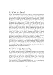
Induced<br />
EMF e<br />
Indian Institute of Technology Madras<br />
S<br />
l<br />
+<br />
Force on conductor<br />
producing V<br />
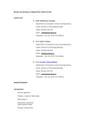
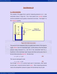
Figure 1: Conductor of length ‘l’ moving through a magnetic field B generate an EMF<br />
where<br />
φ = flux in Webers<br />
t = time in seconds<br />
e = average induced emf in volts.<br />
The above eqn. 1 holds good only when the magnetic circuit is physically the same at<br />
the end as at the beginning and also during the period of change of flux linkages as well. In<br />
practical rotating machinery, however the change of flux linking each individual conductor<br />
during rotation (of either the conductors or the poles) is not clearly defined or cannot be<br />
easily measured. It is therefore more convenient to express this rate of change of flux in terms<br />
of an average flux density (assumed constant) and the relative velocity between this field<br />
and a single conductor moving through it. For the conductor of active length l moving with<br />
a velocity of v in a magnetic field of flux density B, as shown in Fig. 1, the instantaneous<br />
induced emf is expressed as,<br />
e = Blv V olts (2)<br />
where<br />
B= flux density in Tesla (Wb/m 2 )<br />
l = active conductor length (m)<br />
v = relative linear velocity between the conductor and the field (m/s).<br />
This animation would help to understand the concept for a coil rotating in a magnetic field.<br />
2<br />
B<br />
N<br />
-