Synchronous Machines - E-Courses
Synchronous Machines - E-Courses
Synchronous Machines - E-Courses

You also want an ePaper? Increase the reach of your titles
YUMPU automatically turns print PDFs into web optimized ePapers that Google loves.
Electrical <strong>Machines</strong> II Prof. Krishna Vasudevan, Prof. G. Sridhara Rao, Prof. P. Sasidhara Rao<br />
Airgap<br />
Indian Institute of Technology Madras<br />
q axis<br />
d axis<br />
mmf wave<br />
fundamental<br />
component<br />
Stator iron<br />
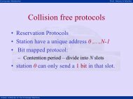
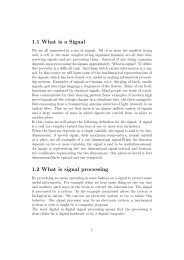
Figure 15: cylindrical rotor mmf wave and its fundamental of a synchronous machine<br />
including leakage flux, is indicated by the dashed lines in Fig. 14. The field coils in Fig. 14 are<br />
represented by filaments but actually (except for the insulation between turns and between<br />
the coil sides and the slot) practically fill the slot more nearly in keeping with fig. 15.<br />
The stepped curve in fig. 15. represents the waveform of the mmf produced by the<br />
distributed field winding if the slots are assumed to be completely filled by the copper in the<br />
coil sides instead of containing current filaments. The sinusoid indicated by the dashed line<br />
in fig. 15 represents approximately the fundamental component of the mmf wave.<br />
The air gap in cylindrical-rotor machines is practically of uniform length except for<br />
the slots in the rotor and in the stator, and when the effect of the slots and the tangential<br />
component of H - which is quite small for the low ratio of air-gap length to the arc subtended<br />
by one pole in conventional machines -are neglected, the stepped mmf wave in fig. 15 produces<br />
a flux-density space wave in which the corners of the steps are rounded due to fringing. The<br />
flux density wave form is therefore more nearly sinusoidal than the mmf waveform when the<br />
effect of the slots is neglected. However, saturation of the iron in the region of maximum<br />
mmf tends to flatten the top of the flux-density wave.<br />
22<br />
Rotor<br />
iron