Synchronous Machines - E-Courses
Synchronous Machines - E-Courses
Synchronous Machines - E-Courses

You also want an ePaper? Increase the reach of your titles
YUMPU automatically turns print PDFs into web optimized ePapers that Google loves.
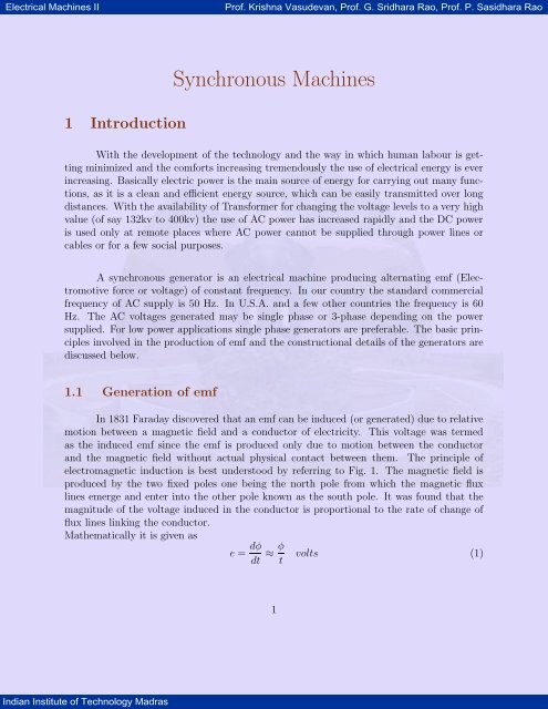
Electrical <strong>Machines</strong> II Prof. Krishna Vasudevan, Prof. G. Sridhara Rao, Prof. P. Sasidhara Rao<br />
1 Introduction<br />
Indian Institute of Technology Madras<br />
<strong>Synchronous</strong> <strong>Machines</strong><br />
With the development of the technology and the way in which human labour is getting<br />
minimized and the comforts increasing tremendously the use of electrical energy is ever<br />
increasing. Basically electric power is the main source of energy for carrying out many functions,<br />
as it is a clean and efficient energy source, which can be easily transmitted over long<br />
distances. With the availability of Transformer for changing the voltage levels to a very high<br />
value (of say 132kv to 400kv) the use of AC power has increased rapidly and the DC power<br />
is used only at remote places where AC power cannot be supplied through power lines or<br />
cables or for a few social purposes.<br />
A synchronous generator is an electrical machine producing alternating emf (Electromotive<br />
force or voltage) of constant frequency. In our country the standard commercial<br />
frequency of AC supply is 50 Hz. In U.S.A. and a few other countries the frequency is 60<br />
Hz. The AC voltages generated may be single phase or 3-phase depending on the power<br />
supplied. For low power applications single phase generators are preferable. The basic principles<br />
involved in the production of emf and the constructional details of the generators are<br />
discussed below.<br />
1.1 Generation of emf<br />
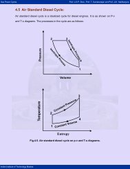
In 1831 Faraday discovered that an emf can be induced (or generated) due to relative<br />
motion between a magnetic field and a conductor of electricity. This voltage was termed<br />
as the induced emf since the emf is produced only due to motion between the conductor<br />
and the magnetic field without actual physical contact between them. The principle of<br />
electromagnetic induction is best understood by referring to Fig. 1. The magnetic field is<br />
produced by the two fixed poles one being the north pole from which the magnetic flux<br />
lines emerge and enter into the other pole known as the south pole. It was found that the<br />
magnitude of the voltage induced in the conductor is proportional to the rate of change of<br />
flux lines linking the conductor.<br />
Mathematically it is given as<br />
e = dφ<br />
dt<br />
≈ φ<br />
t<br />
1<br />
volts (1)
Electrical <strong>Machines</strong> II Prof. Krishna Vasudevan, Prof. G. Sridhara Rao, Prof. P. Sasidhara Rao<br />
Induced<br />
EMF e<br />
Indian Institute of Technology Madras<br />
S<br />
l<br />
+<br />
Force on conductor<br />
producing V<br />
Figure 1: Conductor of length ‘l’ moving through a magnetic field B generate an EMF<br />
where<br />
φ = flux in Webers<br />
t = time in seconds<br />
e = average induced emf in volts.<br />
The above eqn. 1 holds good only when the magnetic circuit is physically the same at<br />
the end as at the beginning and also during the period of change of flux linkages as well. In<br />
practical rotating machinery, however the change of flux linking each individual conductor<br />
during rotation (of either the conductors or the poles) is not clearly defined or cannot be<br />
easily measured. It is therefore more convenient to express this rate of change of flux in terms<br />
of an average flux density (assumed constant) and the relative velocity between this field<br />
and a single conductor moving through it. For the conductor of active length l moving with<br />
a velocity of v in a magnetic field of flux density B, as shown in Fig. 1, the instantaneous<br />
induced emf is expressed as,<br />
e = Blv V olts (2)<br />
where<br />
B= flux density in Tesla (Wb/m 2 )<br />
l = active conductor length (m)<br />
v = relative linear velocity between the conductor and the field (m/s).<br />
This animation would help to understand the concept for a coil rotating in a magnetic field.<br />
2<br />
B<br />
N<br />
-
Electrical <strong>Machines</strong> II Prof. Krishna Vasudevan, Prof. G. Sridhara Rao, Prof. P. Sasidhara Rao<br />
Indian Institute of Technology Madras<br />
Thus the instantaneous voltage e and the average value E of the induced emf are<br />
e<br />
Em<br />
e = Emsinωt = Emsinθ<br />
θ = ωt π 2π<br />
Figure 2: Sinusoidal voltage waveform<br />
the same if the flux densityBand the relative velocityv are both uniform and constant. In<br />
an alternator we want the instantaneous emf to be varying in a sinusoidal manner as shown<br />
in fig. 2. Hence we should have a field system which will produce a sinusoidal distribution<br />
of flux density in the plane perpendicular to the plane of motion of the conductor.Then,<br />
e = Em sin ωt = Em sin θ (3)<br />
We have assumed that the conductor is moved in a direction perpendicular to the<br />
magnetic field as shown in Fig. 1. Eqn. 1 or Eqn. 2 are valid only for this mutually orthogonal<br />
condition for B and v. The other possible cases of motion of conductor with respect to B<br />
are shown in Fig.3 in addition to the mutually orthogonal condition of Fig. 1. When the<br />
conductor moves parallel to B, the induced emf will be zero because the rate of change of<br />
flux linkage is zero as the conductor does not link any new flux line/lines. To account for this<br />
condition of operation, Eqn. 2 must be multiplied by some factor, that takes into account<br />
the direction of motion of conductor so as to make ‘e’ zero for this condition of operation<br />
although B,l andv are finite quantities. Intuitively we may infer that this factor must be a<br />
sine function as it has a zero value at 0 ◦ and also at 180 ◦ and a maximum value at 90 ◦ .<br />
Indeed the emf equation for the general case of a conductor moving in any direction with<br />
respect to the field as shown in Fig. 3 is given by<br />
e = Blv sin θ (4)<br />
where θ is the angle formed between B and v always taking B as the reference. All other<br />
quantities are the same as in Eqn. 2.<br />
3
Electrical <strong>Machines</strong> II Prof. Krishna Vasudevan, Prof. G. Sridhara Rao, Prof. P. Sasidhara Rao<br />
V<br />
V V V V<br />
Indian Institute of Technology Madras<br />
V<br />
B<br />
S N<br />
(a) Conductor moving at right angles<br />
to magnetic field<br />
V VV V V V<br />
B<br />
S N<br />
V<br />
θ<br />
(c) Conductor moving at any angle<br />
across to magnetic field<br />
V V V V<br />
B<br />
S N<br />
V<br />
(b) Conductor moving parallel to magnetic<br />
field<br />
B<br />
θ<br />
S 180 N<br />
0-θ (d) Conductor moving at any angle<br />
across magnetic field<br />
Figure 3: Effect of change of flux linkages on induced EMF in a conductor<br />
4
Electrical <strong>Machines</strong> II Prof. Krishna Vasudevan, Prof. G. Sridhara Rao, Prof. P. Sasidhara Rao<br />
1.2 Direction of induced e.m.f<br />
Induced EMF<br />
Indian Institute of Technology Madras<br />
S<br />
V<br />
V V V V<br />
Field<br />
Motion<br />
(a) Right-hand rule<br />
V<br />
B<br />
S N<br />
(b) orthogonal relations<br />
N<br />
Figure 4: Fleming’s right hand rule for direction of induced EMF<br />
The direction of the induced emf is given by Fleming’s Right Hand Rule which<br />
states: If the thuMb, First finger and the seCond finger of the right hand are stretched<br />
out and held in three mutually perpendicular directions such that the First finger is hold<br />
pointing in the direction of the magnetic field and the thuMb pointing in the direction of<br />
motion, then the seCond finger will be pointing in the direction of the induced emf such that<br />
the current flows in that direction. As shown in Fig. 4 the induced emf is in a direction so as<br />
to circulate current in the direction shown by the middle finger. Schematically we indicate<br />
the direction of the emf by a dot (or a cross) as shown in Fig. 5(a) to represent an emf so<br />
5
Electrical <strong>Machines</strong> II Prof. Krishna Vasudevan, Prof. G. Sridhara Rao, Prof. P. Sasidhara Rao<br />
as to send current in a direction perpendicular to the plane of the paper and out of it. A<br />
cross will indicate the emf of opposite polarity Fig. 5(b). Although the Right Hand Rule<br />
assumes the magnetic filed to be stationary, we can also apply this rule to the case of a<br />
stationary conductor and moving magnetic field, by assuming that the conductor is moving<br />
in the opposite direction. For example, as shown in Fig. 4 the direction of the induced emf<br />
will be the same if the poles producing the field had been moved upwards.<br />
1.3 Electromagnetic Force<br />
The motion of the conductor in a magnetic field can be imparted by the application<br />
of an external mechanical force to the conductor. In such a case the mechanical work<br />
done in moving the conductor is converted to an electric energy in agreement with the law<br />
of conservation of energy. The electric energy is not produced by the magnetic field since<br />
the field is not changed or destroyed in the process. The name electro mechanical energy<br />
conversion is given to the process of converting energy from mechanical form obtained from<br />
a prime mover, such as an IC engine, water/steam turbine etc, into electric energy.<br />
The emf induced in the conductor will circulate a current through it if a closed circuit<br />
is formed by an external connection. The direction of the current flowing in the conductor<br />
will be such as to oppose the cause of it as stated by Lenz’s Law. A current carrying<br />
conductor located in a magnetic field will experience a force given by,<br />
Indian Institute of Technology Madras<br />
f = Bli (5)<br />
In other words, whenever a change in flux linkages occur, an emf is induced that<br />
tends to set up a current in such a direction as to produce a magnetic flux that opposes the<br />
cause of it. Thus if a current carrying conductor is placed in a magnetic field as shown in<br />
Fig. 5 the current tends to produce a magnetic field in the direction shown by the dotted<br />
circles.<br />
The direction of the flux lines around the current carrying conductor can be easily<br />
determined by corkscrew Rule -which states that the flux lines will be in the same direction<br />
as the rotation of a right threaded screw so as to advance in the direction of flow of current.<br />
As a result the magnetic field, for the case shown in Fig. 5(a), is strengthened at the top and<br />
weakened at the bottom of the conductor, thereby setting up a force to move the conductor<br />
downwards. For the case of a Generator, the conductor must be moved up against this<br />
counter force or the opposing force. Similarly the current is to be supplied to the conductor<br />
against the emf generated (known as the counter emf or back emf) in the conductor as it<br />
moves due to the motor action. Thus, the same machine can be operated as a generator<br />
6
Electrical <strong>Machines</strong> II Prof. Krishna Vasudevan, Prof. G. Sridhara Rao, Prof. P. Sasidhara Rao<br />
Indian Institute of Technology Madras<br />
Motor<br />
Direction<br />
of force<br />
Generator<br />
Generator<br />
Direction<br />
of force<br />
Motor<br />
(a)-Current, entering the plane of paper<br />
(b)-Current coming out of the plane of paper<br />
Figure 5: Force on a current carrying conductor in a magnetic field<br />
7
Electrical <strong>Machines</strong> II Prof. Krishna Vasudevan, Prof. G. Sridhara Rao, Prof. P. Sasidhara Rao<br />
or a motor, depending on whether we supply mechanical power or electrical power to it,<br />
respectively.<br />
1.4 Elementary AC. Generators<br />
Indian Institute of Technology Madras<br />
a<br />
V<br />
N-turn<br />
arm ature<br />
winding<br />
Stator<br />
V<br />
Rotor<br />
V<br />
V<br />
Field winding<br />
-a<br />
V<br />
Flux paths<br />
Figure 6: Elementary synchronous generator<br />
The generators shown in figures and discussed in the earlier sections are clearly<br />
impractical for a number of reasons. The main reason is that such generators require a prime<br />
mover that imparts linear or reciprocating motion to the conductor. Most of the commercial<br />
prime movers provide rotary motion in the commercial generators. The conductors of most<br />
commercial generators are rotated about a central axis of a shaft. The conductors are housed<br />
in slots cut in a cylindrical structure (made of magnetic material) known as the armature.<br />
The armature is supported at both ends by means of bearings attached to the shaft that<br />
goes through the center of the armature. The armature is rotated inside the field structure<br />
by providing a small gap between these two members. This gap is known as the air gap and<br />
is usually of the order of 1 to 1.5 cms. If the air gap is maintained constant throughout the<br />
spread of the pole arc, we have a fairly constant flux density under it in a plane perpendicular<br />
to the plane of the conductor’s motion. i.e. in a radial direction with respect to the field and<br />
armature structure. Since the emf is also proportional to B, the flux density in the air gap of<br />
AC. generators is arranged to be distributed as closely to a sine wave as possible by suitable<br />
shaping (chamfering as it is technically known) of the pole shoe. Since the relative motion<br />
8
Electrical <strong>Machines</strong> II Prof. Krishna Vasudevan, Prof. G. Sridhara Rao, Prof. P. Sasidhara Rao<br />
between the conductors and the magnetic flux lines is responsible for the production of emf,<br />
it is immaterial whether the conductors are rotated or the magnetic flux producing poles are<br />
rotated. In most of the alternators it is the field that is rotated rather than the conductors. In<br />
an alternator the external connection to the load can be taken directly from the conductors<br />
since there is no need for any rectification as in a DC generator. In a DC generator the<br />
rectification of the emf is achieved through a mechanical rectifier—- the commutator and<br />
brush arrangement. More over the load current supplied by the alternator can be easily<br />
supplied from stationary coils without any difficulty as there will be so sparkling and weartear<br />
of the brushes and slip rings. Where as the low values of D.C excitation current to the<br />
field coils can be easily sent through the slip rings and brush arrangement. Thus the usual<br />
arrangement in an elementary synchronous generator is as shown in Fig. 6. The conductors<br />
are housed in slots cut in the armature structure. Only a single coil of N turns, indicated in<br />
its cross-section by the two coil sides a and -a placed in diametrically opposite slots on the<br />
inner periphery of the stator (i.e. the armature, as it is a stationary member here) is shown<br />
in Fig. 6.<br />
The conductors forming these coil sides are parallel to the shaft of the machine and<br />
are connected in series by end connections not shown in the figure. The coils are actually<br />
formed by taking a continuous copper wire of suitable cross section round a diamond shaped<br />
bobbin. The completed coil is shown in Fig. 7. The copper wire is usually of fine linen<br />
covered, cotton covered or enamel covered so as to have sufficient insulation between the<br />
conductors of the same coil. The actual layout and interconnection of various coils so as to<br />
obtain the required voltage from the synchronous machine (alternator) is presented in the<br />
following section.<br />
2 <strong>Synchronous</strong> Machine Armature Windings<br />
2.1 Winding Types<br />
A three phase winding, in extremely simplified form, is shown in Fig. 8. The start<br />
and finish of all the coils in phase A are designated, respectively, as SA and FA. Phase A<br />
is shown as a solid line in the figure, phase B as a dashed line, and phase C as a dotted<br />
line. Note that each winding does not start and finish under the same pole. Further, note<br />
that the two coil sides of a given coil lie in identical magnetic conditions of opposite polarity.<br />
This implies that when seen from the coil terminals, the emfs produced in the two coil sides<br />
add up. If we assume that the poles on the rotor are moving to the left as shown, then<br />
the relative motion of the armature conductors is to the right. This implies that identical<br />
magnetic conditions will be seen by conductors of phase A, followed by phase C, followed by<br />
Indian Institute of Technology Madras<br />
9
Electrical <strong>Machines</strong> II Prof. Krishna Vasudevan, Prof. G. Sridhara Rao, Prof. P. Sasidhara Rao<br />
Indian Institute of Technology Madras<br />
(a) (b)<br />
(c) (d)<br />
Figure 7: The completed coil<br />
10
Electrical <strong>Machines</strong> II Prof. Krishna Vasudevan, Prof. G. Sridhara Rao, Prof. P. Sasidhara Rao<br />
V<br />
Indian Institute of Technology Madras<br />
b<br />
_<br />
S S<br />
N N<br />
+<br />
SB SC SA<br />
FB FC FA<br />
+<br />
SB<br />
b<br />
+<br />
_ SB<br />
+<br />
_<br />
_<br />
(a) (b)<br />
SA<br />
FB<br />
FA FC<br />
Figure 8: Concentrated three-phase,half-coil wave winding with one slot per phase(one coil<br />
side per slot and instantaneous polarity and phase relation of coils)<br />
phase B. The induced emfs in phases A,C and B may be said to produce a phase sequence of<br />
ACBACBA.The time interval between two phases to achieve identical magnetic conditions<br />
would depend on the relative speed of motion, and on the spatial seperation of the phases. In<br />
Fig 8, the phases are so laid out that each phase is seperated from another by 120 electrical<br />
degrees (360 ◦ being defined by the distance to achieve identical magnetic conditions).<br />
As the distance between two adjacent corresponding points on the poles is 180 electrical<br />
degrees, we can see that the distance between the coil side at the start of A and that<br />
at the start of C must be 120 electrical degrees. Thus, the leading pole tip of a unit north<br />
pole moving to the left in Fig. 8 will induce identical voltages in corresponding coil sides<br />
A, C, and B, respectively, 120 electrical degrees apart. Note that phase B lags phase A by<br />
240 electrical degrees or leads phase A by 120 electrical degrees.Fig. 8(b) is a representation<br />
that is frequently used to depict the windings of the three phases and the phase relationship<br />
between them.<br />
The winding depicted in Fig. 8 is an open winding since both ends of the windings<br />
have been brought out for suitable connections. It is a wave winding since it progresses from<br />
pole to pole. It is a concentrated winding because all the coils of one phase are concentrated<br />
in the same slot under one pole. It is a half-coil winding because there is only one-half of<br />
11<br />
SC
Electrical <strong>Machines</strong> II Prof. Krishna Vasudevan, Prof. G. Sridhara Rao, Prof. P. Sasidhara Rao<br />
a coil (one coil side) in each slot. It is a full-pitch winding because the coil sides of one<br />
coil are 180 ◦ electrical degrees apart i.e., they lie under identical magnetic conditions, but of<br />
opposite polarity under adjacent poles.<br />
Fig. 9, on the other hand shows the coils of a single phase,(A, in this case) distributed<br />
winding distributed over two slots under each pole.<br />
2.1.1 Half-coil and whole-coil windings<br />
Half-coil (also called single-layer) windings are sometimes used in small induction<br />
motor stators and in the rotors of small wound-rotor induction motors. A cross section<br />
of a half-coil, single-layer winding is shown in Fig. 9(a). Like the dc dynamo armature<br />
windings, most commercial armatures for ac synchronous generators are of the full or wholecoil<br />
two-layer type, shown in cross section at the right in Fig. 9(c)(ii). The whole-coil,<br />
two-layer winding gets its name from the fact that there are two coil sides (one coil) per slot.<br />
Fig. 9(a) shows a single-layer, half-coil lap windings;Fig. 9(b) shows a double-layer, full-coil<br />
lap winding.A cross section of a single layer (half-coil) winding is shown in Fig. 9(c)(i).<br />
2.1.2 Chorded or fractional -pitch windings<br />
Whereas most single-layer windings are full-pitch windings, the two-layer, whole-coil<br />
windings are generally designed on an armature as a chorded or fractional-pitch windings.<br />
This common practice stems from the fact that the primary advantage of the whole-coil<br />
windings is that it permits the use of fractional-pitch coils in order to save copper. As will<br />
be shown later, fractional-pitch windings, when used in ac synchronous and asynchronous<br />
generator armatures, in addition to saving copper, (1) reduce the MMF harmonics produced<br />
by the armature winding and (2) reduce the EMF harmonics induced in the windings,<br />
without reducing the magnitude of the fundamental EMF wave to a great extent. For the<br />
three reasons cited, fractional-pitch windings are almost universally used in ac synchronous<br />
generator armatures.<br />
2.1.3 EMF of Fractional Pitch Windings<br />
In the case of an ac generator using a full-pitch coil, such as that shown in Fig. 8, the<br />
two coil sides span a distance exactly equal to the pole pitch of 180 electrical degrees. As a<br />
result, the EMFs induced in a full-pitch coil are such that the coil side EMFs are in phase,<br />
Indian Institute of Technology Madras<br />
12
Electrical <strong>Machines</strong> II Prof. Krishna Vasudevan, Prof. G. Sridhara Rao, Prof. P. Sasidhara Rao<br />
SA<br />
Indian Institute of Technology Madras<br />
N N<br />
S S<br />
(a)<br />
S N S N S<br />
SA<br />
N<br />
(b)<br />
FA<br />
(i) Single layer (ii) Double layer<br />
(c)<br />
Figure 9: Distributed and concentrated half-coil and whole-coil windings<br />
13<br />
N<br />
FA
Electrical <strong>Machines</strong> II Prof. Krishna Vasudevan, Prof. G. Sridhara Rao, Prof. P. Sasidhara Rao<br />
Indian Institute of Technology Madras<br />
Coil side emf<br />
E1<br />
em f<br />
E2<br />
Coil Ec<br />
Figure 10: Full pitch coil<br />
coil side emf<br />
β/2<br />
Ε1<br />
coil emf<br />
Ε1cosβ/2 Ε1cosβ/2<br />
Figure 11: Fractional-pitch coil- Coil EMF in terms of coil side EMFs for fractional-pitch<br />
coil<br />
as shown in Fig. 10. The total coil voltage Ec is 2E1, if E1 is the emf induced in a coil-side.<br />
In the case of the two-layer winding shown in Fig. 9(b), note that the coil span of<br />
single coil is less than the pole span of 180 electrical degrees. The EMF induced in each coil<br />
side is not in phase, and the resultant coil voltage Ec would be less than the arithmetic sum<br />
of the EMF of each coil side, or less than 2E1. It is obvious that 2E1 must be multiplied by a<br />
factor,kp, that is less than unity, to get the proper value for coil voltage Ec (or Ec = 2E1kp).<br />
The pitch factor kp is given by<br />
kp = Ec<br />
2E1<br />
= phasor sum of the EMF of the two coil sides<br />
β<br />
arithmetic sum of the EMF ′ s of the two coil sides<br />
The pitch factor may be quantified in terms of angles as follows. If we assume that<br />
the induced EMFs of two coils, E1 and E2, are out of phase with respect to each other by<br />
some angle β as shown in Fig. 11, then the angle between E1 and the resultant coil voltage<br />
Ec is β<br />
2 .The resultant coil voltage Ec is from Eqn. 6 and Fig. 11.<br />
Ε2<br />
Εc<br />
(6)<br />
Ec = 2E1 cos β<br />
2 = 2E1kp. (7)<br />
14
Electrical <strong>Machines</strong> II Prof. Krishna Vasudevan, Prof. G. Sridhara Rao, Prof. P. Sasidhara Rao<br />
and, therefore,<br />
kp = cos β<br />
(8)<br />
2<br />
The angle β is 1800 minus the number of electrical degrees spanned by the coil, for a shortpitched<br />
coil. For a full pitched coil, therefore, kp = 1 as β = 0.<br />
as<br />
Indian Institute of Technology Madras<br />
Since β is the supplementary of the coil span, the pitch factor kp may also be expressed<br />
kp = sin p0<br />
2<br />
where p 0 is the span of the coil in electrical degrees.<br />
It is sometimes convenient to speak of an armature coil span as having a<br />
fractional pitch expressed as a fraction e.g., a 5<br />
11<br />
pitch, or an pitch, etc. This fraction is<br />
6 12<br />
infact the ratio of the number of slots spanned by a coil to the number of slots in a full pitch.<br />
In such a case, the electrical degrees spanned, p0 is 5<br />
6 ∗ 1800 , or 1500 ; or 11<br />
12 ∗ 1800 or 1650 ;<br />
etc. The pitch factor kp is still computed as in Eqn. 9. Over pitched coils are not normaly<br />
used in practice as there is an increased requirement of copper wire without any additional<br />
advantage.<br />
2.1.4 Relation between Electrical and Mechanical Degrees of Rotation<br />
As stated earlier there are 180 electrical degrees between the centres of two adjacent<br />
north and south poles. Since 360 electrical degrees represents a full cycle of sinusoidal EMF,<br />
we are interested in determining how many sinusoidal cycles are generated in one complete<br />
mechanical rotation, i.e., 360 mechanical degrees for a machine having P poles. The number<br />
of electrical degrees as a function of degrees of mechanical rotation is<br />
α =<br />
P θ<br />
2<br />
(9)<br />
= pθ. (10)<br />
where P is the number of poles (always an even integer), p is the number of pole-pairs, and<br />
θ is the number of mechanical degrees of rotation.<br />
Thus, a two-pole machine generates one cycle of sinusoid a four-pole machine generates<br />
two cycles and so on, in one full revolution of the armature.<br />
15
Electrical <strong>Machines</strong> II Prof. Krishna Vasudevan, Prof. G. Sridhara Rao, Prof. P. Sasidhara Rao<br />
2.1.5 Distributed windings and distribution (or Belt) factor<br />
The windings shown in Fig. 8. and Fig. 9(b) are called concentrated windings because<br />
all the coil sides of a given phase are concentrated in a single slot under a given pole.<br />
For Fig. 8., in determining the induced ac voltage per phase, it would be necessary only to<br />
multiply the voltage induced in any given coil by the number of series-connected coils in<br />
each phase. This is true for the winding shown in Fig. 8 because the conductors of each coil,<br />
respectively, lie in the same position with respect to the N and S poles as other series coils<br />
in the same phase. Since these individual coil voltages are induced in phase with each other,<br />
they may be added arithmetically. In otherwords, the induced emf per phase is the product<br />
of the emf in one coil and the number of series connected coils in that phase.<br />
Concentrated windings in which all conductors of a given phase per pole are concentrated<br />
in a single slot, are not commercially used because they have the following disadvantages,<br />
1. They fail to use the entire inner periphery of the stator iron efficiently.<br />
2. They make it necessary to use extremely deep slots where the windings are concentrated.<br />
This causes an increase in the mmf required to setup the airgap flux.<br />
3. The effect of the second disadvantage is to also increase the armature leakage flux and<br />
the armature reactance.<br />
4. They result in low copper-to-iron ratios by not using the armature iron completely.<br />
5. They fail to reduce harmonics as effectively as distributed windings.<br />
For the five reasons just given, it is more advantageous to distribute the armature<br />
winding, using more slots and a uniform spacing between slots, than to concentrate<br />
the windings in a few deep slots.<br />
When the slots are distributed around the armature uniformly, the winding that is<br />
inserted is called a distributed winding. A distributed lap winding is shown in Fig. 12. Note<br />
that two coils in phase belt A are displaced by one slot angle (the angular displacement<br />
between two successive slots) with respect to each other. The induced voltages of each of<br />
these coils will be displaced by the same degree to which the slots have been distributed, and<br />
the total voltage induced in any phase will be the phasor sum of the individual coil voltages.<br />
For an armature winding having four coils distributed over say, 2/3 rd of a pole-pitch, in<br />
four slots, the four individual coil side voltages are represented by phasors in Fig. 13 as<br />
displaced by some angle α, the number of electrical degrees between adjacent slots, known<br />
Indian Institute of Technology Madras<br />
16
Electrical <strong>Machines</strong> II Prof. Krishna Vasudevan, Prof. G. Sridhara Rao, Prof. P. Sasidhara Rao<br />
Indian Institute of Technology Madras<br />
1 2 3 4 5 6 7 8 9 10 11 12<br />
AS<br />
V<br />
Figure 12: Lap winding<br />
as slot angle. It is 30 0 for the case of 4 slots per phase belt. Voltages Ec1, Ec2, etc., are the<br />
individual coil voltages, and n is the number of coils in a given phase belt, in general.<br />
For a machine using n slots for a phase belt, the belt or distribution factor by which<br />
the arithmetic sum of the individual coil voltages must be multiplied in order to yield the<br />
phasor sum is given by:<br />
kd = Eφ<br />
nEc<br />
= 2OA sin(nα/2)<br />
n.2OA(sin(α/2))<br />
= AN<br />
nEc<br />
=<br />
V<br />
= 2AM<br />
n ∗ AC<br />
2AM<br />
n ∗ 2AB =<br />
AF<br />
2AM<br />
n ∗ 2OA sin α<br />
2<br />
where all terms are previously defined<br />
As in the case of Eqn. 6., the computation of kd in terms of voltages (either theoretical<br />
or actual) is impractical. The construction of Fig. 13 in which perpendiculars have been<br />
drawn to the center of each of the individual coil voltage phasors to a common center of<br />
radius ’r’ (using dashed lines) serves to indicate that α/2 is the angle BOA. Coil side voltage<br />
AB equals OA sin α/2, and coil voltage represented by chord AC equals 2OA sin α/2. For n<br />
coils in series per phase, chord AN, is also 2OA sin nα/2, and the distribution or belt factor<br />
kd is<br />
kd = Eφ<br />
=<br />
nEc<br />
2OA sin(nα/2) sin nα/2<br />
= (12)<br />
n.2OA(sin(α/2)) n sin α/2<br />
where<br />
17<br />
(11)
Electrical <strong>Machines</strong> II Prof. Krishna Vasudevan, Prof. G. Sridhara Rao, Prof. P. Sasidhara Rao<br />
Indian Institute of Technology Madras<br />
A<br />
B<br />
C<br />
α<br />
α<br />
D E<br />
M<br />
O<br />
nα<br />
Figure 13: Determination of distribution factor<br />
n is the number of slots per pole per phase (s.p.p)<br />
α is the number of electrical degrees between adjacent slots i.e. slot angle<br />
It should be noted from Eqn. 12. that the distribution factor kd for any fixed or given<br />
number of phases is a sole function of the number of distributed slots under a given pole.<br />
As the distribution of coils (slots/pole) increases, the distribution factor kd decreases. It is<br />
not affected by the type of winding, lap or wave, or by the number of turns per coil, etc.<br />
2.2 Generated EMF in a <strong>Synchronous</strong> Generator<br />
It is now possible to derive the computed or expected EMF per phase generated<br />
in a synchronous generator. Let us assume that this generator has an armature winding<br />
consisting of a total number of coils C, each coil having a given number of turns Nc. Then<br />
the total number of turns in any given phase of generator armature is<br />
Np = CNc<br />
m<br />
But Faraday’s law (section 1-3) states that the average voltage induced in a single<br />
turn of two coil sides is<br />
Eav = φ<br />
t<br />
(14)<br />
18<br />
N<br />
(13)
Electrical <strong>Machines</strong> II Prof. Krishna Vasudevan, Prof. G. Sridhara Rao, Prof. P. Sasidhara Rao<br />
The voltage induced in one conductor is 2φ/(1/s) = 2φs, where s=speed of rotation<br />
in r.p.s, for a 2 pole generator. Furthermore, when a coil consisting of Nc turns rotates in a<br />
uniform magnetic field, at a uniform speed, the average voltage induced in an armature coil<br />
is<br />
E av<br />
coil = 4φNcs V olts (15)<br />
where φ is the number of lines of flux (in Webers) per pole, Nc is number of turns per coil, s is<br />
the relative speed in revolutions/second (rps) between the coil of Nc turns and the magnetic<br />
field φ.<br />
A speed s of 1 rps will produce a frequency f of 1 Hz. Since f is directly proportional<br />
and equivalent to s, (for a 2-pole generator) replacing the latter in Eqn. 15, for all the series<br />
turns in any phase,<br />
E av<br />
phase = 4φNpf V olts (16)<br />
However, in the preceding section we discovered that the voltage per phase is made<br />
more completely sinusoidal by intentional distribution of the armature winding. The effective<br />
rms value of a sinusoidal ac voltage is 1.11 times the average value. The effective ac voltage<br />
per phase is<br />
Eeff = 4.44φNpf V olts (17)<br />
But eqn. 17 is still not representative of the effective value of the phase voltage generated<br />
in an armature in which fractional-pitch coils and a distributed winding are employed.<br />
Taking the pitch factor kp and the distribution factor kd into account, we may now write the<br />
equation for the effective value of the voltage generated in each phase of an AC synchronous<br />
generator as<br />
Indian Institute of Technology Madras<br />
Egp = 4.44φNpfkpkd V olts (18)<br />
2.3 Frequency of an A.C. <strong>Synchronous</strong> Generator<br />
Commercial ac synchronous generators have many poles and may rotate at various<br />
speeds, either as alternators or as synchronous or induction motors.Eqn. 14 was derived for<br />
a two-pole device in which the generated EMF in the stationary armature winding changes<br />
direction every half-revolution of the two-pole rotor. One complete revolution will produce<br />
one complete positive and negative pulse each cycle. The frequency in cycles per second<br />
(Hz) will, as stated previously, depend directly on the speed or number of revolutions per<br />
second (rpm/60) of the rotating field.<br />
19
Electrical <strong>Machines</strong> II Prof. Krishna Vasudevan, Prof. G. Sridhara Rao, Prof. P. Sasidhara Rao<br />
If the ac synchronous generator has multiple poles (having, say, two, four, six, or<br />
eight poles...), then for a speed of one revolution per second (1 rpm/60), the frequency<br />
per revolution will be one, two, three, or four ..., cycles per revolution, respectively. The<br />
frequency per revolution, is therefore, equal to the number of pairs of poles. Since the<br />
frequency depends directly on the speed (rpm/60) and also on the number of pairs of poles<br />
(P/2), we may combine these into a single equation in which<br />
Indian Institute of Technology Madras<br />
f = P<br />
2<br />
∗ rpm<br />
60<br />
where<br />
P is the number of poles<br />
N is the speed in rpm (rev/min)<br />
f is. the frequency in hertz<br />
ω is the speed in radians per second (rad/s).<br />
= P N<br />
120<br />
2.4 Constructional Details of Rotor<br />
= ω<br />
2π<br />
As stated earlier the field windings are provided in the rotor or the rotating member<br />
of the synchronous machine. Basically there are two general classifications -cylindrical rotor<br />
and salient-pole rotor - for large 3 phase synchronous generators.<br />
The cylindrical-rotor construction is peculiar to synchronous generators driven by<br />
steam turbines and which are also known as turbo alternators or turbine generators. Steam<br />
turbines operate at relatively high speeds, 1500 and 3000 rpm being common for 50 Hz,<br />
accounting for the cylindrical-rotor construction, which because of its compactness readily<br />
withstands the centrifugal forces developed in the large sizes at those speeds. In addition,<br />
the smoothness of the rotor contour makes for reduced windage losses and for quiet operation.<br />
Salient-pole rotors are used in low-speed synchronous generators such as those driven<br />
by water wheels. They are also used in synchronous motors. Because of their low speeds<br />
salient-pole generators require a large number of poles as, for example, 60 poles for a 100-rpm<br />
50 Hz generator.<br />
Fig. 14 illustrates two- and four-pole cylindrical rotors along with a developed view<br />
of the field winding for one pair of poles. One pole and its associated field coil of a salientpole<br />
rotor is shown in fig. 14.The stator slots in which the armature winding is embedded<br />
are not shown for reasons of simplicity. The approximate path taken by the field flux, not<br />
20<br />
(19)
Electrical <strong>Machines</strong> II Prof. Krishna Vasudevan, Prof. G. Sridhara Rao, Prof. P. Sasidhara Rao<br />
q ax is<br />
V<br />
Indian Institute of Technology Madras<br />
v<br />
v<br />
v<br />
v<br />
V<br />
N<br />
f’ f<br />
v<br />
v<br />
S<br />
(a)<br />
d ax is<br />
v<br />
v<br />
v<br />
i1<br />
v<br />
(a) (b)<br />
q-axis<br />
(c) (d)<br />
Figure 14: <strong>Synchronous</strong> machines with stator slots and armature windings omitted (a)Twopole<br />
cylindrical rotor,(b) Four-pole cylindrical rotor, (c) Developed view of two pole cylindrical<br />
rotor field structure, (d) Salient pole and field coil<br />
21<br />
V<br />
S<br />
V<br />
V<br />
V<br />
V<br />
V<br />
V<br />
V<br />
N<br />
N<br />
V<br />
V<br />
V<br />
V<br />
V<br />
V<br />
d-axis<br />
V<br />
S<br />
V
Electrical <strong>Machines</strong> II Prof. Krishna Vasudevan, Prof. G. Sridhara Rao, Prof. P. Sasidhara Rao<br />
Airgap<br />
Indian Institute of Technology Madras<br />
q axis<br />
d axis<br />
mmf wave<br />
fundamental<br />
component<br />
Stator iron<br />
Figure 15: cylindrical rotor mmf wave and its fundamental of a synchronous machine<br />
including leakage flux, is indicated by the dashed lines in Fig. 14. The field coils in Fig. 14 are<br />
represented by filaments but actually (except for the insulation between turns and between<br />
the coil sides and the slot) practically fill the slot more nearly in keeping with fig. 15.<br />
The stepped curve in fig. 15. represents the waveform of the mmf produced by the<br />
distributed field winding if the slots are assumed to be completely filled by the copper in the<br />
coil sides instead of containing current filaments. The sinusoid indicated by the dashed line<br />
in fig. 15 represents approximately the fundamental component of the mmf wave.<br />
The air gap in cylindrical-rotor machines is practically of uniform length except for<br />
the slots in the rotor and in the stator, and when the effect of the slots and the tangential<br />
component of H - which is quite small for the low ratio of air-gap length to the arc subtended<br />
by one pole in conventional machines -are neglected, the stepped mmf wave in fig. 15 produces<br />
a flux-density space wave in which the corners of the steps are rounded due to fringing. The<br />
flux density wave form is therefore more nearly sinusoidal than the mmf waveform when the<br />
effect of the slots is neglected. However, saturation of the iron in the region of maximum<br />
mmf tends to flatten the top of the flux-density wave.<br />
22<br />
Rotor<br />
iron
Electrical <strong>Machines</strong> II Prof. Krishna Vasudevan, Prof. G. Sridhara Rao, Prof. P. Sasidhara Rao<br />
2.5 Excitation Systems for <strong>Synchronous</strong> <strong>Machines</strong><br />
A number of arrangements for supplying direct current to the fields of synchronous<br />
machines have come into use. Adjustments in the field current may be automatic or manual<br />
depending upon the complexity and the requirements of the power system to which the<br />
generator is connected.<br />
Excitation systems are usually 125 V up to ratings of 50kW with higher voltages for<br />
the larger ratings. The usual source of power is a direct-connected exciter, motor- generator<br />
set, rectifier, or battery. A common excitation system in which a conventional dc shunt<br />
generator mounted on the shaft of the synchronous machine furnishes the field excitation<br />
is shown in fig. 16. The output of the exciter (i.e., the field current of the synchronous<br />
machine) is varied by adjusting the exciter field rheostat. A somewhat more complex system<br />
that makes use of a pilot exciter, a compound dc generator also mounted on the generator<br />
shaft, which in turn excites the field of the main exciter, is shown in fig. 16. This arrangement<br />
makes for greater rapidity of response, a feature that is important in the case of synchronous<br />
generators when there are disturbances on the system to which the generator is connected.<br />
In some installations a separate motor-driven exciter furnishes the excitation. An induction<br />
motor is used instead of a synchronous motor because in a severe system disturbance a<br />
synchronous motor may pullout of synchronism with the system. In addition, a large flywheel<br />
is used to carry the exciter through short periods of severely reduced system voltage.<br />
2.5.1 Brushless Excitation System<br />
The brushless excitation system eliminates the usual commutator, collector rings, and<br />
brushes. One arrangement in which a permanent-magnet pilot exciter, an ac main exciter,<br />
and a rotating rectifier are mounted on the same shaft as the field of the ac turbogenerator<br />
is shown in fig. 17. The permanent-magnet pilot excitor has a stationary armature and a<br />
rotating permanent magnetic field. It feeds 400 Hz, three-phase power to a regulator, which<br />
in turn supplies regulated dc power to the’ stationary field of a rotating-armature ac exciter,<br />
The output of the ac exciter is rectified by diodes and delivered to the field of the turbo<br />
generator.<br />
Brush less excitation systems have been also used extensively in the much smaller<br />
generators employed in aircraft applications where reduced atmospheric pressure intensifies<br />
problems of brush deterioration. Because of their mechanical simplicity, such systems lend<br />
themselves to military and other applications that involve moderate amounts of power.<br />
Indian Institute of Technology Madras<br />
23
Electrical <strong>Machines</strong> II Prof. Krishna Vasudevan, Prof. G. Sridhara Rao, Prof. P. Sasidhara Rao<br />
Main<br />
exciter<br />
Exciter-field<br />
Exciter<br />
field<br />
rheostat<br />
v<br />
v<br />
v<br />
Exciter(dc generator<br />
Pilot<br />
exciter<br />
Main<br />
exciter<br />
<strong>Synchronous</strong>machine<br />
Prime mover for generator<br />
Figure 16: Conventional excitation systems for synchronous machines<br />
Indian Institute of Technology Madras<br />
Brushes<br />
Pilot exciter Main exciter<br />
v v<br />
Sh.f Ser.f<br />
(a)<br />
v v<br />
(b)<br />
Rotor<br />
slip<br />
rings<br />
Rotor<br />
<strong>Synchronous</strong><br />
generator<br />
(c)<br />
24<br />
(d)<br />
or<br />
Mechanical load for motor<br />
<strong>Synchronous</strong> machine<br />
Three-phase<br />
armature<br />
Stator<br />
Prime mover<br />
<strong>Synchronous</strong> generator
Electrical <strong>Machines</strong> II Prof. Krishna Vasudevan, Prof. G. Sridhara Rao, Prof. P. Sasidhara Rao<br />
Indian Institute of Technology Madras<br />
Rotating<br />
components<br />
Stationary<br />
components<br />
Pilot exciter<br />
permanent magnet<br />
field<br />
Pilot exciter<br />
armature<br />
ac exciter<br />
armature Rectifier<br />
ac exciter<br />
field<br />
Regulator<br />
ac<br />
turbine<br />
generator<br />
field<br />
Figure 17: Brushless excitation system<br />
2.6 The Action of the <strong>Synchronous</strong> Machine<br />
ac turbine<br />
generator stator<br />
Just like the DC generator, the behaviour of a <strong>Synchronous</strong> generator connected to<br />
an external load is not the same as at no-load. In order to understand the action of the<br />
<strong>Synchronous</strong> machine when it is loaded, let us take a look at the flux distributions in the<br />
machine when the armature also carries a current. Unlike in the DC machine here the<br />
current peak and the emf peak will not occur in the same coil due to the effect of the pf of<br />
the load. In other words the current and the induced emf will be at their peaks in the same<br />
coil only for upf loads. For zpf (lagging) loads, the current reaches its peak in a coil which<br />
falls behind that coil wherein the induced emf is at its peak by nearly 90 electrical degrees or<br />
half a pole-pitch. Likewise for zpf (leading) loads, the current reaches its peak in a coil which<br />
is ahead of that coil wherein the induced emf is at its peak by nearly 90 electrical degrees<br />
or half a pole-pitch.. For simplicity, let us assume the resistance and leakage reactance of<br />
the stator windings to be negligible. Let us also assume the magnetic circuit to be linear i.e.<br />
the flux in the magnetic circuit is deemed to be proportional to the resultant ampere-turns<br />
- in other words we assume that there is no saturation of the magnetic core. Thus the e.m.f.<br />
induced is the same as the terminal voltage, and the phase-angle between current and e.m.f.<br />
is determined only by the pf of the external load connected to the synchronous generator.<br />
2.6.1 Armature Reaction<br />
In order to understand more clearly let us consider a sketch of a stretched-out synchronous<br />
machine shown in Fig. 18 which shows the development of a fixed stator carrying<br />
25
Electrical <strong>Machines</strong> II Prof. Krishna Vasudevan, Prof. G. Sridhara Rao, Prof. P. Sasidhara Rao<br />
Flux<br />
produced<br />
by<br />
main field<br />
Indian Institute of Technology Madras<br />
Flux produced by<br />
armature current<br />
N S<br />
(a)The effect of armature current while supplying a pure resistance load<br />
Eo<br />
δ<br />
(b)Phasor diagram<br />
E<br />
Figure 18: Stretched out synchronous generator<br />
26<br />
I
Electrical <strong>Machines</strong> II Prof. Krishna Vasudevan, Prof. G. Sridhara Rao, Prof. P. Sasidhara Rao<br />
Indian Institute of Technology Madras<br />
N S<br />
(a)The effect of armature current when the machine operates as a motor at u.p.f<br />
E<br />
Eo<br />
V<br />
(b)Phasor diagram<br />
Figure 19: Stretched out synchronous motor<br />
27<br />
I
Electrical <strong>Machines</strong> II Prof. Krishna Vasudevan, Prof. G. Sridhara Rao, Prof. P. Sasidhara Rao<br />
Indian Institute of Technology Madras<br />
N S N<br />
(a)The effect of armature current when it supplies a zpf(lagging) load<br />
Eo<br />
E<br />
(b)Phasor diagram<br />
Figure 20: Stretched out synchronous generator<br />
28<br />
I
Electrical <strong>Machines</strong> II Prof. Krishna Vasudevan, Prof. G. Sridhara Rao, Prof. P. Sasidhara Rao<br />
S<br />
Indian Institute of Technology Madras<br />
N<br />
(a)The effect of armature current when it supplies a zpf(leading) load<br />
I<br />
E<br />
(b)Phasor diagram<br />
Eo<br />
Figure 21: Stretched out synchronous generator<br />
29<br />
S
Electrical <strong>Machines</strong> II Prof. Krishna Vasudevan, Prof. G. Sridhara Rao, Prof. P. Sasidhara Rao<br />
armature windings, and a rotor carrying field windings and capable of rotation within it.<br />
The directions of the currents and the flux distribution are as shown in Fig. 18, when the<br />
emf induced in the stator coils is the maximum. The coil links no resultant flux but is in the<br />
position of greatest rate of change of flux. The coil position shown is also that for maximum<br />
current when the current is in phase with the voltage: i.e for a pure resistive load. The<br />
current in the coil has no effect on the total flux per pole, but causes a strengthening on<br />
one side and a weakening on the other side of the pole shoes. Thus the armature conductors<br />
find themselves in the circumstances illustrated in Fig. 18, and a torque is produced by<br />
the interaction of the main flux φm with the current in the conductors. The torque thus<br />
produced is seen to be opposed to the direction of motion of the rotor - the force on the<br />
conductors is such as to push them to the left and by reaction to push the rotor to the right<br />
(as the armature coils are stationary). The rotor is rotated by a prime mover against this<br />
reaction, so that the electrical power, the product El, is produced by virtue of the supply<br />
of a corresponding mechanical power. Thus it is evident from the distortion of the main<br />
flux distribution that electrical energy is converted from mechanical energy and the machine<br />
operates as a generator. An unidirectional torque is maintained as the stator conductors<br />
cut N-Pole and S-Pole fluxes alternately resulting in alternating emfs at a frequency equal<br />
to the number of pole-pairs passed per second and the currents also alternate with the emf.<br />
The assumption that the conditions shown in Fig. 18 represent co-phasal emf and current<br />
is not quite true. The strengthening of the resultant flux on the right of the poles and an<br />
equivalent amount of weakening on the left effectively shift the main field flux axis against<br />
the direction of rotation, so that the actual e.m.f. E induced in the armature winding is an<br />
angle δ behind the position E0 that it would occupy if the flux were undistorted as shown in<br />
the adjacent phasor diagram pertaining to this condition of operation. Thus the effect of a<br />
resistive (upf) load connected to a synchronous generator is to shift the main field flux axis<br />
by what is known as cross-magnetization.<br />
The action of a synchronous generator operating as a motor at upf is shown in Fig. 19.<br />
Just like a DC motor, a synchronous motor also requires an externally-applied voltage V in<br />
order to circulate in it a current in opposition to the induced e.m.f. E. The coil is shown<br />
in the position of maximum induced emf and current, but the current is oppositely directed<br />
to that shown in Fig. 18. Again the m.m.f. of the coil does not affect the total flux in the<br />
common magnetic circuit, but distorts the distribution in such a way as to produce a torque<br />
in the same direction as the motion. The machine is a motor by virtue of the electrical input<br />
VI causing a torque in the direction of motion. The flux distortion causes a shift of the flux<br />
axis across the poles, so that the actual e.m.f. E is an angle δ ahead of the position E0<br />
that it would occupy if the flux were undistorted as shown in the adjacent phasor diagram<br />
pertaining to this condition of operation.<br />
Indian Institute of Technology Madras<br />
30
Electrical <strong>Machines</strong> II Prof. Krishna Vasudevan, Prof. G. Sridhara Rao, Prof. P. Sasidhara Rao<br />
Next let us consider this generator to be connected to a purely inductive load so that<br />
the current I in the coils lags behind the e.m.f. E by 90 electrical degrees i.e. corresponding<br />
to a quarter-period. in time scale. Since the coil-position in Fig. 18 or Fig. 19 represents<br />
that for maximum e.m.f., the poles would have moved through half a pole-pitch before the<br />
current in the coil has reached a maximum as shown in Fig. 20. As seen from this figure it<br />
is obvious that the ampere-turns of the stator coils are now in direct opposition to those on<br />
the pole, thereby reducing the total flux and e.m.f. Since the stator and rotor ampere-turns<br />
act in the same direction, there is no flux-distortion, no torque, and hence no additional<br />
mechanical power. This circumstance is in accordance with the fact that there is also no<br />
electrical power output as E and I are in phase quadrature. The phasor Eo represents the<br />
e,m.f. with no demagnetizing armature current, emphasizing the reduction in e.m.f. due to<br />
the reduced flux.<br />
Likewise, when this generator is connected to a purely capacitive load i.e the current I<br />
in the coil leads the emf E by 90 electrical degrees, the conditions are such that the armature<br />
AT and the field AT will be assisting each other as shown in Fig. 21.<br />
When the generator supplies a load at any other power factor intermediate between<br />
unity and zero, a combination of cross- and direct-magnetization is produced on the magnetic<br />
circuit by the armature current. The cross-magnetization is distorting and torque-producing<br />
as in (figure1); the direct-magnetization decreases (for lagging currents) or increases (for<br />
leading currents) the ampere-turns acting on the magnetic circuit as in Fig. 20and Fig. 21,<br />
affecting the main flux and the e.m.f. accordingly.<br />
For a motor the torque is reversed on account of the current reversal, and the directmagnetizing<br />
effect is assisting the field ampere-turns for lagging currents. The action of<br />
the armature ampere-turns as described above is called armature-reaction. The effect of<br />
the armature reaction has a far-reaching influence on the performance of the synchronous<br />
motor, particularly as regards the power factor at which it operates and the amount of field<br />
excitation that it requires.<br />
2.6.2 Behaviour of a loaded synchronous generator<br />
The simple working of the synchronous machine can be summed up as follows:<br />
A synchronous machine driven as a generator produces e.m.f.’s in its armature windings at<br />
a frequency f = np. These e.m.f.’s when applied to normal circuits produce currents of the<br />
same frequency. Depending on the p.f of the load, field distortion is produced, generating<br />
a mechanical torque and demanding an input of mechanical energy to satisfy the electrical<br />
Indian Institute of Technology Madras<br />
31
Electrical <strong>Machines</strong> II Prof. Krishna Vasudevan, Prof. G. Sridhara Rao, Prof. P. Sasidhara Rao<br />
output. As the stator currents change direction in the same time as they come from one<br />
magnetic polarity to the next, the torque is unidirectional. The torque of individual phases<br />
is pulsating just like in a single-phase induction machine - but the torque of a three-phase<br />
machine is constant for balanced loads.<br />
For the cylindrical rotor machine the fundamental armature reaction can be more<br />
Indian Institute of Technology Madras<br />
B<br />
Ft<br />
C ’ A<br />
A ’<br />
pole axis<br />
Figure 22: <strong>Synchronous</strong> generator supplying a lagging pf load<br />
convincingly divided into cross-magnetizing and direct-magnetizing components, since the<br />
uniform air-gap permits sinusoidal m.m.f s to produce more or less sinusoidal fluxes. Fig. 22<br />
shows a machine with two poles t and he currents in the three-phase armature winding<br />
produce a reaction field having a sinusoidally-distributed fundamental component and an<br />
axis coincident, for the instant considered, with that of one phase such as A − A ′<br />
. The rotor<br />
windings, energized by direct current, give also an approximately sinusoidal rotor m.m.f.<br />
distribution. The machine is shown in operation as a generator supplying a lagging current.<br />
The relation of the armature reaction m.m.f. Fa to the field m.m.f. Ft is shown in Fig. 23. The<br />
Fa sine wave is resolved into the components Faq corresponding to the cross-component and<br />
Fad corresponding to the direct-component, which in this case demagnetizes in accordance<br />
with Figure 3. Fad acts in direct opposition to Ft and reduces the effective m.m.f. acting<br />
round the normal magnetic circuit. Faq shifts the axis of the resultant m.m.f. (and flux)<br />
backward against the direction of rotation of the field system.<br />
32<br />
C<br />
B ’<br />
Fa
Electrical <strong>Machines</strong> II Prof. Krishna Vasudevan, Prof. G. Sridhara Rao, Prof. P. Sasidhara Rao<br />
Indian Institute of Technology Madras<br />
mmf of<br />
main field<br />
Pole axis<br />
mmf of A-A ’<br />
Figure 23: Sinusoidal distribution of the components of armature reaction in a synchronous<br />
generator<br />
N<br />
N<br />
S<br />
Figure 24: Elementary synchronous motor action- Atraction of the unlike poles keep the<br />
rotor locked to the rotating field produced in the stator<br />
33<br />
S<br />
Fa<br />
Pole axis<br />
Faq<br />
Fad
Electrical <strong>Machines</strong> II Prof. Krishna Vasudevan, Prof. G. Sridhara Rao, Prof. P. Sasidhara Rao<br />
2.6.3 Behaviour of a loaded synchronous motor<br />
Likewise when a synchronous machine operates as a motor with a mechanical load<br />
on its shaft, it draws an alternating current which interacts with the main flux to produce a<br />
driving torque. The torque remains unidirectional only if the rotor moves one pole-pitch per<br />
half-cycle; i.e. it can run only at the synchronous speed. In a balanced three-phase machine,<br />
the armature reaction due to the fundamental component of the current is a steady mmf<br />
revolving synchronously with the rotor - its constant cross-component producing a constant<br />
torque by interaction with the main flux, while its direct-component affects the amount of the<br />
main flux. A very simple way of regarding a synchronous motor is illustrated in Fig. 24. The<br />
stator, like that of the induction motor produces a magnetic fie]d rotating at synchronous<br />
speed. The poles on the rotor (salient-pole is shown in Fig. 24, only for clarity), excited by<br />
direct current in their field windings, undergo magnetic attraction by the stator poles, and<br />
are dragged round to align themselves and locked up with with the stator poles (of opposite<br />
polarity- obviously). On no load the axes of the stator and rotor poles are practically coincident.<br />
When a retarding torque is applied to the shaft, the rotor tends to fall behind. In<br />
doing so the attraction of the stator on the rotor becomes tangential to an extent sufficient to<br />
develop a counter torque - however the rotor continues to rotate only at synchronous speed.<br />
The angular shift between the stator and rotor magnetic axes represents the torque (or load)<br />
angle (as shown later, in the phasor diagram). This angle naturally increases with the mechanical<br />
load on the shaft. The maximum possible load is that which retards the rotor so<br />
that the tangential attraction is a maximum. (It will be shown later that the maximum possible<br />
value for the torque angle is 90 electrical degrees - corresponding to a retardation of the<br />
rotor pole by one half of a pole pitch). If the load be increased above this amount, the rotor<br />
poles comes under the influence of a like pole and the attraction between the stator and rotor<br />
poles ceases and the rotor comes to a stop. At this point we say that the synchronous motor<br />
pulled out of step. This situation arises much above the rated loads in any practical machine.<br />
It is to be noted that the magnetic field shown in Fig. 24.It is only diagrammatic<br />
and for better understanding of the action of the synchronous machine - the flux lines may<br />
be considered as elastic bands which will be stretched by application of the mechanical load<br />
on the shaft. Actually the flux lines will enter or leave the stator and rotor surfaces nearly<br />
normally, on account of the high permeability of these members. In a salient-pole machine<br />
the torque is developed chiefly on the sides of the poles and on the sides of the teeth in a<br />
non-salient-pole machine.<br />
Indian Institute of Technology Madras<br />
34
Electrical <strong>Machines</strong> II Prof. Krishna Vasudevan, Prof. G. Sridhara Rao, Prof. P. Sasidhara Rao<br />
2.7 Concept of <strong>Synchronous</strong> Reactance<br />
The operation of the synchronous machine can be reduced to comparatively simple<br />
expression by the convenient concept of synchronous reactance. The resultant linkage of flux<br />
with any phase of the armature of a synchronous machine is due, as has been seen, to the<br />
combined action of the field and armature currents. For a simple treatment it is convenient<br />
to separate the resultant flux in-to components: (a) the field flux due to the field current<br />
alone; and (b) the armature flux due to the armature current alone. This separation does<br />
not affect qualitative matters, but its quantitative validity rests on the assumption that the<br />
magnetic circuit has a constant permeability. In brief the simplifying assumptions are...<br />
1. The permeability of all parts of the magnetic circuit of the synchronous machine is<br />
constant - in other words the field and armature fluxes can be treated separately as<br />
proportional to their respective currents so that their effects can be superposed.<br />
2. The air gap is uniform, so that the armature flux is not affected by its position relative<br />
to the poles - in other words we assume the rotor to be cylindrical<br />
3. The distribution of the field flux in the air gap is sinusoidal.<br />
4. The armature winding is uniformly distributed and carries balanced sinusoidal currents:<br />
- in other words, the harmonies are neglected so that the armature flux is directly<br />
proportional to the fundamental component of the armature reaction mmf implying<br />
that the armature reaction mmf is distributed sinusoidally and rotates at synchronous<br />
speed with constant magnitude.<br />
Assumption (1) is roughly fulfilled when the machine works at low saturation; (2)<br />
and (3) are obviously inaccurate with salient-pole machines and assumption 4) is commonly<br />
made and introduces negligible error in most cases. The behaviour of an “ideal” synchronous<br />
machine can be indicated qualitatively when the above assumptions (1) to (4) are made.<br />
The phasor diagrams (Fig. 18to Fig. 21) for the several conditions contain the phasors<br />
of two emfs viz. Eo and E . The latter is the e.m.f actually existing, while the former is<br />
that which would be induced under no-load conditions, i.e. with no armature current (or<br />
armature reaction).<br />
Indian Institute of Technology Madras<br />
35
Electrical <strong>Machines</strong> II Prof. Krishna Vasudevan, Prof. G. Sridhara Rao, Prof. P. Sasidhara Rao<br />
Thus Eo is the e.m.f. corresponding to the flux produced by the field winding only,<br />
while E is that actually produced by the resultant flux due to the combined effect of stator<br />
and rotor ampere-turns. The actual e.m.f. E can be considered as Eo plus a fictitious e.m.f.<br />
proportional to the armature current.<br />
Eo<br />
Eo Er<br />
E<br />
Er<br />
Er<br />
E<br />
Indian Institute of Technology Madras<br />
I<br />
Er<br />
Er<br />
(a)Generator (b)Motor unity power factor<br />
I<br />
(c) Generator (d)Generator zero power factor<br />
Figure 25: Pertaining to <strong>Synchronous</strong> Reactance<br />
I<br />
I<br />
Er<br />
E Eo<br />
Fig. 25 is redrawn in this manner to correspond with part (b) of Figures 1 to<br />
4, introducing the fictitious emf. Er such that the following phasor relationship is satisfied:<br />
E = Eo + Er<br />
It can be seen from Fig. 25, that Er, is always in phase-quadrature with armature current and<br />
proportional to it (as per the four assumptions (1) to (4) above). The emf Er is thus similar<br />
36<br />
V<br />
Er<br />
Eo<br />
Eo<br />
E<br />
Er<br />
(20)
Electrical <strong>Machines</strong> II Prof. Krishna Vasudevan, Prof. G. Sridhara Rao, Prof. P. Sasidhara Rao<br />
to an emf induced in an inductive reactance, so that the effect of armature reaction is exactly<br />
the same as if the armature windings had a reactance xa = Er/Ia .This fictitious reactance<br />
xa can added to the armature leakage reactance xl and the combined reactance ( xa + xl )<br />
is known as the synchronous reactance xs. The behavior of a synchronous machine can be<br />
easily predicted from the equivalent circuit developed using this synchronous reactance xs,<br />
as explained in the following section.<br />
2.8 Approximation of the Saturated <strong>Synchronous</strong> Reactance<br />
Economical size requires the magnetic circuit to be somewhat saturated under normal<br />
operating conditions. However, the machine is unsaturated in the short- circuit test, and<br />
the synchronous reactance based on short-circuits and open- circuit test data is only an<br />
approximation at best. Nevertheless, there are many studies in which a value based on rated<br />
open-circuit voltage and the short circuit current suffices. Hence, in fig. 29, if oc is rated<br />
voltage, ob is the required no-load field current, which also produces the armature current<br />
o’e on short circuit. The synchronous impedance is, accordingly,<br />
Indian Institute of Technology Madras<br />
Zdu = oc<br />
√ 3o ′ e<br />
Except in very small machines, the synchronous reactance is much greater than the<br />
resistance ra of the armature and the saturated value as well as the unsaturated value of the<br />
synchronous reactance is considered equal to the magnitude of the synchronous impedance<br />
(21)<br />
Xd = (Z 2 d − r 2 a) 1<br />
2 ≈ Zd (22)<br />
The line of in Fig. 29 is more nearly representative of the saturated machine than is<br />
the air-gap line. On the basis of this line, an estimate of the field current can be obtained<br />
for a given terminal voltage, load current, and power factor. This is done by calculating Eaf<br />
and making use of the saturated synchronous reactance as follows.<br />
Eaf = V + ZdI (23)<br />
The field current is that required to produce Eat on the line of.<br />
2.8.1 Open-circuit and Short-circuit Tests<br />
The effect of saturation on the performance of synchronous machines is taken into<br />
account by means of the magnetization curve and other data obtained by tests on an existing<br />
machine. Only some basic test methods are considered. The unsaturated synchronous<br />
37
Electrical <strong>Machines</strong> II Prof. Krishna Vasudevan, Prof. G. Sridhara Rao, Prof. P. Sasidhara Rao<br />
impedance and approximate value of the saturated synchronous impedance can be obtained<br />
form the open-circuit and short-circuit tests.<br />
In the case of a constant voltage source having constant impedance, the impedance<br />
can be found by dividing the open-circuit terminal voltage by the short circuit current.<br />
However, when the impedance is a function of the open-circuit voltage, as it is when the<br />
machine is saturated, the open-circuit characteristics or magnetization curve in addition to<br />
the short-circuit characteristic is required.<br />
Indian Institute of Technology Madras<br />
v<br />
+ + v<br />
Eaf ~<br />
v<br />
Eoc=Eaf<br />
v<br />
v<br />
+<br />
Eaf ~<br />
Figure 26: <strong>Synchronous</strong> generator(a) Open circuit (b) Short circuit<br />
The unsaturated synchronous reactance is constant because the reluctance<br />
of the unsaturated iron is negligible. The equivalent circuit of one phase of a polyphase<br />
synchronous machine is shown in fig. 26 for the open-circuit condition and for the short<br />
circuit condition. Now Eaf is the same in both cases when the impedance<br />
z = Eaf<br />
Isc . where Eaf is the open-circuit volts per phase and Isc is the short-circuit current<br />
per phase.<br />
2.8.2 Open-circuit Characteristic<br />
To obtain the open-circuit characteristic the machine is driven at its rated speed<br />
without load. Readings of line-to-line voltage are taken for various values of field current.<br />
The voltage except in very low-voltage machines is stepped down by means of instrument<br />
potential transformers. Fig. 27 shows the open-circuit characteristic or saturation curve. Two<br />
sets of scales are shown; one, line to-line volts versus field current in amperes and the other<br />
per-unit open-circuit voltage versus per-unit field current. If it were not for the magnetic<br />
38<br />
v<br />
Isc<br />
v
Electrical <strong>Machines</strong> II Prof. Krishna Vasudevan, Prof. G. Sridhara Rao, Prof. P. Sasidhara Rao<br />
Open-circuit voltage,line to line<br />
Per unit field current<br />
1.0<br />
Air- gap line<br />
Field current,A<br />
Indian Institute of Technology Madras<br />
Rated voltage<br />
Per unit field current<br />
OCC 1.0<br />
1.0<br />
Per unit open-circuit.A<br />
Short-circuit current.A<br />
Field current A<br />
(a) (b)<br />
Figure 27: (a) Open circuit characteristic and (b) Short-circuit characteristic<br />
39<br />
1.0<br />
Per unit short-circuit current
Electrical <strong>Machines</strong> II Prof. Krishna Vasudevan, Prof. G. Sridhara Rao, Prof. P. Sasidhara Rao<br />
saturation of the iron, the open-circuit characteristic would be linear as represented by the<br />
air-gap line in Fig. 27. It is important to note that 1.0 per unit field current corresponds to<br />
the value of the field current that would produce rated voltage if there were no saturation.<br />
On the basis of this convention, the per-unit representation is such as to make the air-gap<br />
lines of all synchronous machines identical.<br />
2.8.3 Short circuit Test<br />
dc<br />
source<br />
If<br />
Field<br />
circuit<br />
Indian Institute of Technology Madras<br />
v<br />
(a) (b)<br />
Figure 28: Connections for short-circuit test<br />
The three terminals of the armature are short -circuited each through a currentmeasuring<br />
circuit, which except for small machines is an instrument current transformer with<br />
an ammeter in its secondary. A diagram of connections in which the current transformers<br />
are omitted is shown in fig. 28.<br />
The machine is driven at approximately synchronous (rated) speed and measurements<br />
of armature short-circuit current are made for various values of field current, usually<br />
up to and somewhat above rated armature current. The short-circuit characteristic (i.e.<br />
armature short circuit current versus field current) is shown in Fig. 27. In conventional<br />
synchronous machines the short-circuit characteristic is practically linear because the iron<br />
is unsaturated up to rated armature current and somewhat beyond, because the magnetic<br />
axes of the armature and the field practically coincide (if the armature had zero resistance<br />
the magnetic axes would be in exact alignment), and the field and armature mmfs oppose<br />
each other.<br />
40<br />
Ia<br />
Ib<br />
Ic
Electrical <strong>Machines</strong> II Prof. Krishna Vasudevan, Prof. G. Sridhara Rao, Prof. P. Sasidhara Rao<br />
Indian Institute of Technology Madras<br />
Figure 29: Open-circuit and short circuit characteristic<br />
41
Electrical <strong>Machines</strong> II Prof. Krishna Vasudevan, Prof. G. Sridhara Rao, Prof. P. Sasidhara Rao<br />
2.8.4 Unsaturated <strong>Synchronous</strong> Impedance<br />
The open circuit and short-circuit characteristics are represented on the same graph<br />
in Fig. 29. The field current 08 produces a line-to line voltage oc on the air- gap line, which<br />
would be the open-circuit voltage if there were no saturation. The same value of field current<br />
produces the armature current o’d and the unsaturated synchronous reactance is<br />
Indian Institute of Technology Madras<br />
Zdu = oc<br />
√ 3o ′ d Ω phase,forastar connected armature (24)<br />
When the open-circuit characteristic, air-gap line, and the short-circuit characteristic<br />
are plotted in per-unit, then the per unit value of unsaturated synchronous reactance equals<br />
the per-unit voltage on the air-gap line which results from the same value of field current<br />
as that which produces rated short-circuit (one-per unit) armature current. In Fig. 29 this<br />
would be the per-unit value on the air gap line corresponding to the field current og.<br />
3 <strong>Synchronous</strong> Generator Operation<br />
3.1 Cylindrical Rotor Machine<br />
The synchronous generator, under the assumption of constant synchronous reactance,<br />
may be considered as representable by an equivalent circuit comprising an ideal winding<br />
in which an e.m.f. Et proportional to the field excitation is developed, the winding being<br />
connected to the terminals of the machine through a resistance r and reactance (X+Xa) = Xs<br />
all per phase. This is shown in fig. 30. the principal characteristics of the synchronous<br />
generator will be obtained qualitatively from this circuit.<br />
3.1.1 Generator Load Characteristics<br />
Consider a synchronous generator driven at constant speed and with constant excitation.<br />
On open circuit the terminal voltage V is the same as the open circuit e.m.f. Et<br />
Suppose a unity-power-factor load be connected to the machine. The .flow of load current<br />
produces a voltage drop Izs in the synchronous impedance, and terminal voltage V is reduced.fig.<br />
31 shows the complexor diagram for three values of load. It will be seen that<br />
the angle σ between Et and V increases with load, indicating a shift of he flux across the<br />
pole faces due to cross- magnetization. The terminal voltage is obtained from the complex<br />
summation<br />
V + Iz, = EtorV = E − Iz8<br />
(25)<br />
42
Electrical <strong>Machines</strong> II Prof. Krishna Vasudevan, Prof. G. Sridhara Rao, Prof. P. Sasidhara Rao<br />
Indian Institute of Technology Madras<br />
v<br />
Et<br />
v<br />
v<br />
Et<br />
v<br />
v<br />
xa x r I<br />
v<br />
E<br />
v<br />
v<br />
V<br />
v<br />
v<br />
v<br />
Load<br />
(a) (b)<br />
xs r I<br />
Zs<br />
v<br />
v<br />
V<br />
v<br />
v<br />
v<br />
Load<br />
(c) (d)<br />
Et<br />
Et<br />
V<br />
V<br />
Ixs<br />
Ixa<br />
Izs<br />
Figure 30: Equivalent circuits<br />
43<br />
<<br />
E<br />
β<br />
><br />
Ix<br />
V<br />
V<br />
φ<br />
Ir<br />
V<br />
Ir<br />
v<br />
< >< ><br />
σ<br />
φ<br />
V<br />
V<br />
v<br />
φ<br />
V<br />
I<br />
I
Electrical <strong>Machines</strong> II Prof. Krishna Vasudevan, Prof. G. Sridhara Rao, Prof. P. Sasidhara Rao<br />
V<br />
Et<br />
Ea<br />
Et Ea<br />
V<br />
V<br />
E<br />
Ea<br />
V<br />
V<br />
Indian Institute of Technology Madras<br />
V<br />
I<br />
Ea<br />
V<br />
Ea<br />
V<br />
E<br />
V<br />
I V<br />
V<br />
V V1<br />
(a) (b)<br />
I<br />
V<br />
V<br />
(c) (d)<br />
Figure 31: Variation of voltage with load at constant Excitation<br />
44<br />
I<br />
Ea<br />
Ea<br />
Et<br />
Ea<br />
V<br />
V<br />
V<br />
Et<br />
E
Electrical <strong>Machines</strong> II Prof. Krishna Vasudevan, Prof. G. Sridhara Rao, Prof. P. Sasidhara Rao<br />
Indian Institute of Technology Madras<br />
Algebraically this can be written<br />
<br />
V = (E2 t − I2X2 8) − Ir<br />
for non-reactive loads. Since normally r is small compared with X8<br />
Perfect of no-load voltage<br />
100<br />
0<br />
0.0 Leading<br />
(26)<br />
V 2 + I 2 Xs ≈ E 2 t = constant (27)<br />
0.8 Leading<br />
0.9 Leading<br />
1.0<br />
0.9 Lagging<br />
0.0 Lagging<br />
Isc<br />
100<br />
Perfect of full -load current<br />
Figure 32: Generator Load characteristics<br />
so that the V/I curve, fig. 32, is nearly an ellipse with semi-axes Et and Isc. The<br />
current Isc. The current Isc that which flows when the load resistance is reduced to zero.<br />
The voltage V falls to zero also and the machine is on short-circuit with V = 0 and<br />
I = Isc = Et/Zs ≈ Et/Xs<br />
For a lagging load of zero power-factor, diagram is given in fig. 31 The voltage<br />
is given as before and since the resistance in normal machines is small compared with the<br />
synchronous reactance, the voltage is given approximately by<br />
V ≈ Et − IXs<br />
45<br />
(28)<br />
(29)
Electrical <strong>Machines</strong> II Prof. Krishna Vasudevan, Prof. G. Sridhara Rao, Prof. P. Sasidhara Rao<br />
which is the straight line marked forcos φ = 0 lagging in fig. 32. A leading load of<br />
zero power factor fig. 31. will have the voltage<br />
Indian Institute of Technology Madras<br />
V ≈ Et + IXs<br />
another straight line for which, by reason of the direct magnetizing effect of leading<br />
currents, the voltage increases with load.<br />
Intermediate load power factors produce voltage/current characteristics resembling<br />
those in fig. 32. The voltage-drop with load (i.e. the regulation) is clearly dependent upon<br />
the power factor of the load. The short-circuit current Isc which the load terminal voltage<br />
falls to zero may be about 150 per cent (1.5 per unit) of normal current in large modern<br />
machines.<br />
3.1.2 Generator Voltage-Regulation<br />
The voltage-regulation of a synchronous generator is the voltage rise at the terminals<br />
when a given load is thrown off, the excitation and speed remaining constant. The voltagerise<br />
is clearly the numerical difference between Et and V, where V is the terminal voltage<br />
for a given load and Et is the open-circuit voltage for the same field excitation. Expressed<br />
as a fraction, the regulation is<br />
(30)<br />
ε = (Et − V )/V perunit (31)<br />
Comparing the voltages on full load (1.0 per unit normal current) in fig. 32, it will<br />
be seen that much depends on the power factor of the load. For unity and lagging power<br />
factors there is always a voltage drop with increase of load, but for a certain leading power<br />
factor the full-load regulation is zero, i.e. the terminal voltage is the same for both full and<br />
no-load conditions. At lower leading power sectors the voltage rises with increase of load,<br />
and the regulation is negative. From fig. 30, the regulation for a load current I at power<br />
factor cos φ is obtained from the equality<br />
E 2 t = (V cos φ + Ir) 2 + (V sin φ + Ix5) 2<br />
E from which the regulation is calculated, when both Et and V are known or found.<br />
3.1.3 Generator excitation for constant voltage<br />
Since the e.m.f. Et is proportional to the excitation when the synchronous reactance<br />
is constant, the above Eqn. can be applied directly to obtain the excitation necessary to<br />
46<br />
(32)
Electrical <strong>Machines</strong> II Prof. Krishna Vasudevan, Prof. G. Sridhara Rao, Prof. P. Sasidhara Rao<br />
Indian Institute of Technology Madras<br />
200<br />
100<br />
0.0 Lagging<br />
0.8 Lagging<br />
0.9 Lagging<br />
0<br />
0 100<br />
0.9 Leading<br />
0.8 Leading<br />
0.0 Leading<br />
Percent of full -load current<br />
Figure 33: Generator Excitation for constant Voltage<br />
maintain constant output voltage for all loads. All unity-and lagging power-factor loads will<br />
require an increase of excitation with increase of load current, as a corollary of fig. 32. Lowleading-power-factor<br />
loads, on the other hand, will require the excitation to be reduced on<br />
account of the direct magnetizing effect of the zero- power-factor component. Fig. 33 shows<br />
typical e.m.f./current curves for a constant output voltage. The ordinates of Fig. 33 are<br />
marked in percentage of no-load field excitation, to which the e.m.f Et exactly corresponds<br />
when saturation is neglected.<br />
3.1.4 Generator input and output<br />
For any load conditions represented e.g. by fig. 30 the output per phase is P =<br />
V I cos φ. The electrical power converted from mechanical power input is per phase<br />
Resolving Et along I<br />
P1 = EtI cos(φ + σ) (33)<br />
P1 = EtI cos(φ + σ) = (V cos φ + Ir).I = V I cos φ + I 2 R (34)<br />
The electrical input is thus the output plus the I 2 R loss, as might be expected. The<br />
prime mover must naturally supply also the friction, windage and core losses, which do not<br />
appear in the phasor diagram.<br />
47
Electrical <strong>Machines</strong> II Prof. Krishna Vasudevan, Prof. G. Sridhara Rao, Prof. P. Sasidhara Rao<br />
In large machines the resistance is small compared with the synchronous reactance<br />
so that θ = arc tan(xs/r) ≈ 90 ◦ , it can be shown that<br />
Indian Institute of Technology Madras<br />
P = P1 = EtI cos(φ + σ) ≈ (Et/X5).V sin σ (35)<br />
Thus the power developed by a synchronous machine with given values of Et<br />
V and Zs is proportionaltosinσ: or, for small angles, to σ , and the displacement angle σ<br />
representing the change in relative position between the rotor and resultant pole- axes is<br />
proportional to the load power. The term load-,power- or torque-angle may be applied to σ<br />
An obvious deduction from the above Eqn. is that the greater the field excitation<br />
(corresponding to Et the grater is the output per unit angle a: that is, the more stable will<br />
be the operation.<br />
3.2 Salient Pole Rotor Machine<br />
As discussed earlier in Sec. the behaviour of a synchronous machine on load can be<br />
determined by the use of synchronous reactance xs which is nothing but the sum of xa and<br />
xl , where xa is a fictitious reactance representing the effect of armature reaction while xl is<br />
the leakage reactance. It was also mentioned that this method of representing the effect of<br />
armature reaction by a fictitious reactance xa was applicable more aptly only for a cylindrical<br />
rotor (non-salient pole) machine. This was so as the procedure followed therein was valid<br />
only when both the armature and main field m.m.f.’s act upon the same magnetic circuit<br />
and saturation effects are absent.<br />
3.2.1 Theory of Salient-pole machines:(Blondel’s Two-reaction Theory)<br />
It was shown in Sec.(2.6.2) that the effect of armature reaction in the case of a salient<br />
pole synchronous machine can be taken as two components - one acting along the direct<br />
axis (coinciding with the main field pole axis) and the other acting along the quadrature<br />
axis (inter-polar region or magnetic neutral axis) - and as such the mmf components of<br />
armature-reaction in a salient-pole machine cannot be considered as acting on the same<br />
magnetic circuit. Hence the effect of the armature reaction cannot be taken into account by<br />
considering only the synchronous reactance, in the case of a salient pole synchronous machine.<br />
In fact, the direct-axis component Fad acts over a magnetic circuit identical with<br />
that of the main field system and produces a comparable effect while the quadrature-axis<br />
48
Electrical <strong>Machines</strong> II Prof. Krishna Vasudevan, Prof. G. Sridhara Rao, Prof. P. Sasidhara Rao<br />
component Faq acts along the interpolar space, resulting in an altogether smaller effect and,<br />
in addition, a flux distribution totally different from that of Fad or the main field m.m.f.<br />
This explains why the application of cylindrical-rotor theory to salient-pole machines for<br />
predicting the performance gives results not conforming to the performance obtained from<br />
an actual test.<br />
Blondel’s two-reaction theory considers the effects of the quadrature arid direct-axis<br />
components of the armature reaction separately. Neglecting saturation, their different effects<br />
are considered by assigning to each an appropriate value of armature-reaction “reactance,”<br />
respectively xad and xaq . The effects of armature resistance and true leakage reactance ( xl<br />
) may be treated separately, or may be added to the armature reaction coefficients on the<br />
assumption that they are the same, for either the direct-axis or quadrature-axis components<br />
of the armature current (which is almost true). Thus the combined reactance values can be<br />
expressed as :<br />
Indian Institute of Technology Madras<br />
xsd = xad + x1 and xsq = xaq + xl<br />
for the direct- and cross-reaction axes respectively. These values can be determined experimentally<br />
as described in Sec.<br />
In a salient-pole machine, xaq , the cross- or quadrature-axis reactance is smaller than<br />
xad, the direct-axis reactance, since the flux produced by a given current component in that<br />
axis is smaller as the reluctance of the magnetic path consists mostly of the interpolar spaces.<br />
It is essential to clearly note the difference between the quadrature- and direct-axis<br />
components Iaq, and Iad of the armature current Ia , and the reactive and active components<br />
Iaa and Iar. Although both pairs are represented by phasors in phase quadrature, the former<br />
are related to the induced emf. E while the latter are referred to the terminal voltage V .<br />
These phasors are clearly indicated with reference to the phasor diagram of a (salient pole)<br />
synchronous generator supplying a lagging pf load, shown in Fig. 20(a). We have:<br />
Iaq = Ia cos(δ + φ); Iad = Ia sin(δ + φ); and Ia =<br />
(36)<br />
<br />
(I2 aq + I2 ad ) (37)<br />
Iaa = Ia cos(φ); Iar = Ia sin(φ); and Ia = (I2 aa + I2 ar ) (38)<br />
where δ = torque or power angle and φ = the p.f. angle of the load.<br />
The phasor diagram Fig. 20(b) shows the two reactance voltage components Iaq ∗ xaq<br />
and Iad ∗ xad which are in quadrature with their respective components of the armature<br />
49
Electrical <strong>Machines</strong> II Prof. Krishna Vasudevan, Prof. G. Sridhara Rao, Prof. P. Sasidhara Rao<br />
current. The resistance drop Ia ∗ Ra is added in phase with Ia although we could take it as<br />
Iaq ∗ Ra and Iad ∗ Ra separately, which is unnecessary as<br />
Indian Institute of Technology Madras<br />
Ia = Iqd + Iaq<br />
Actually it is not possible to straight-away draw this phasor diagram as the power angle δ is<br />
unknown until the two reactance voltage components Iaq ∗ xsq and Iad ∗ xsd are known. However<br />
this difficulty can be easily overcome by following the simple geometrical construction<br />
shown in Fig. , assuming that the values for terminal voltage V , the load pf angle φ and the<br />
two synchronous reactances xsd and xsq are known to us.<br />
The resistance drop Ia ∗ Ra (length AB) is added to the tip of the voltage phasor<br />
(OA) in phase with the current phasor (i.e. in a direction parallel to OQ ). Then we draw<br />
line BC ( of length equal to Ia ∗ xsq ) and extend it to D such that BD will be (of length<br />
equal to Ia ∗ xsd ) at the extremity B of Ia ∗ Ra and at right-angles to Ia . Draw OC and<br />
extend it (to F ). From D draw the perpendicular DF on OC extended. Then OF represents<br />
the induced voltage E. The proof for this can be given as follows:. If DF is extended to G<br />
such that this line is perpendicular to BG drawn parallel to OF, we have :<br />
BG = BD ∗ cos(90 − (δ + φ)) = Ia ∗ xsd ∗ sin(δ + φ) = Iad ∗ xsd and (39)<br />
GF = CH = BC ∗ sin(90 − (δ + φ)) = Ia ∗ xsq ∗ cos(δ + φ) = Iaq ∗ xsq (40)<br />
3.2.2 1. Power relations in a Salient Pole <strong>Synchronous</strong> Machine:<br />
Neglecting the armature winding resistance, the power output of the generator is<br />
given by:<br />
P = V ∗ Ia ∗ cos φ (41)<br />
This can be expressed in terms of δ, by noting from Fig. that :<br />
Ia ∗ cos φ = Iaq ∗ cos δ + Iad ∗ sin δ (42)<br />
V ∗ cos δ = Eo − Iad ∗ xsd<br />
and V ∗ sin δ = Iaq ∗ xsd<br />
Substituting these in the expression for power, we have.<br />
P = V [(V ∗ sin δ/xsd) ∗ cos δ + (Eo − V ∗ cos δ)/xsd ∗ sin δ] (43)<br />
= (V ∗ Eo/xsd) ∗ sin δ + V 2 ∗ (xsd − xsq)/(2 ∗ xsq ∗ xsq) ∗ sin 2δ<br />
50
Electrical <strong>Machines</strong> II Prof. Krishna Vasudevan, Prof. G. Sridhara Rao, Prof. P. Sasidhara Rao<br />
Indian Institute of Technology Madras<br />
(a) Components of Ia<br />
δ<br />
φ<br />
δ<br />
φ<br />
δ<br />
φ<br />
φ<br />
Iaq<br />
Iad<br />
Ia<br />
(b) Phasor addition of<br />
component drops<br />
Iaq<br />
Q<br />
Ia<br />
I<br />
Iaa<br />
Iad<br />
Iar<br />
(c) Phasor addition using Ia<br />
Ia<br />
(d) Geometric construction<br />
of (c)<br />
o<br />
δ<br />
V<br />
V<br />
V<br />
V<br />
A<br />
Iara<br />
Iara<br />
B<br />
Eo<br />
Iaxsd<br />
C<br />
Eo<br />
Iadxsd<br />
Iaxsq<br />
(90-δ+φ)<br />
E<br />
D<br />
Iaqxsq<br />
Iaqxsq<br />
F<br />
Iadxsd<br />
Figure 34: Phasor diagram of a generator-Two reaction theory<br />
51<br />
Η<br />
G
Electrical <strong>Machines</strong> II Prof. Krishna Vasudevan, Prof. G. Sridhara Rao, Prof. P. Sasidhara Rao<br />
It is clear from the above expression that the power is a little more than that for<br />
a cylindrical rotor synchronous machine, as the first term alone represents the power for a<br />
cylindrical rotor synchronous machine. A term in (sin 2δ) is added into the power - power<br />
angle characteristic of a non-salient pole synchronous machine. This also shows that it is<br />
possible to generate an emf even if the excitation E is zero. However this magnitude is quite<br />
less compared with that obtained with a finite E. Likewise we can show that the machine<br />
develops a torque - called the reluctance torque - as this torque is developed due to the<br />
variation of the reluctance in the magnetic circuit.<br />
3.2.3 Experimental Determination of xd and xq<br />
The unsaturated values of xd and xq of a 3-Phase synchronous machine can be easily<br />
determined experimentally by conducting the following test known as slip test. The rotor of<br />
the synchronous machine is driven by means of a prime mover (usually a DC motor in the<br />
laboratory) at a speed close to the synchronous speed but not equal to it. The armature is<br />
supplied with a low voltage 3-Phase balanced supply through a variac, while the field circuit is<br />
kept open. The armature current varies between two limits since it moves through, since the<br />
synchronously rotating armature mmf acts through the varying magnetic reluctance paths<br />
as it goes from inter-polar axis to pole axis region. The values of xsd and xsq are determined<br />
based on the applied voltage and the armature current values. The ratio of applied voltage<br />
to the minimum value of the armature current gives the direct axis synchronous reactance<br />
xsd which is usually the same as the synchronous reactance xs that we usually determine<br />
from normal no-load and shod-circuit tests as explained in Sec. The ratio of applied voltage<br />
to the maximum value of the armature current gives the the quadrature-axis reactance xsq.<br />
For more accurate determination of these values the oscillogram of the armature current and<br />
voltage form can be recorded.<br />
3.3 Losses and Efficiency<br />
To calculate the efficiency of a synchronous generator, a procedure is to be followed<br />
for establishing the total losses when operating under load. For generators these losses are,<br />
1. Rotational losses such as friction and windage.<br />
2. Eddy current and hysteresis losses in the magnetic circuit<br />
3. Copper losses in the armature winding and in the field coils<br />
4. Load loss due to armature leakage flux causing eddy current and hysteresis losses in<br />
the armature-surrounding iron.<br />
Indian Institute of Technology Madras<br />
52
Electrical <strong>Machines</strong> II Prof. Krishna Vasudevan, Prof. G. Sridhara Rao, Prof. P. Sasidhara Rao<br />
With regard to the losses, the following comments may be made,<br />
1. The rotational losses, which include friction and windage losses, are constant, since the<br />
speed of a synchronous generator is constant. It may be determined from a no-load<br />
test.<br />
2. The core loss includes eddy current and hysteresis losses as a result of normal flux<br />
density changes. It can be determined by measuring the power input to an auxiliary<br />
motor used to drive the generator at no load, with and without the field excited. The<br />
difference in power measured constitutes this loss.<br />
3. The armature and field copper losses are obtained as I 2 A RA and VfIf Since per phase<br />
quantities are dealt with, the armature copper loss for the generator must be multiplied<br />
by the number of phases. The field winding loss is as a result of the excitation current<br />
flowing through the resistance of the field winding.<br />
4. Load loss or stray losses result from eddy currents in the armature conductors and increased<br />
core losses due to distorted magnetic fields. ,Although it is possible to separate<br />
this loss by tests, in calculating the efficiency, it may be accounted for by taking the<br />
effective armature resistance rather than the dc resistance.<br />
Indian Institute of Technology Madras<br />
After all the foregoing losses have been determined, the efficiency η is calculated as,<br />
where η = efficiency,<br />
η =<br />
A = load on the generator (output)<br />
PF = power factor of the load<br />
kV AxP F<br />
∗ 100% (44)<br />
kV AxP F + (totallosses)<br />
The quantity (kV AxPF) is, of course, the real power delivered to the load (in kW)<br />
by the synchronous generator. Thus, it could in general be stated as<br />
η = Pout<br />
Pin<br />
∗ 100 =<br />
Pout<br />
Pout + Plosses<br />
∗ 100 (45)<br />
The input power Pin = Pout + Plosses is the power required from the prime mover to<br />
drive the loaded generator.<br />
53
Electrical <strong>Machines</strong> II Prof. Krishna Vasudevan, Prof. G. Sridhara Rao, Prof. P. Sasidhara Rao<br />
4 Parallel Operation of two Generators<br />
When two synchronous generators are connected in parallel, they have an inherent<br />
tendency to remain in step, on account of the changes produced in their armature currents<br />
by a divergence of phase. Consider identical machines 1 and 2,fig. 35 in parallel and working<br />
on to the same load. With respect to the load, their e.m.f;s are normally in phase: with<br />
respect to the local circuit formed by the two armature windings, however, their e.m.fs are<br />
in phase-opposition, (b). Suppose there to be no external load. If machine 1 for some<br />
reason accelerates, its e.m.f. will draw ahead of that of machine 2. The resulting phase<br />
difference2δcauses e.m.fs to lose phase-opposition in the local circuit so that there is in effect<br />
a local e.m.f Es which will circulate a current Is in the local circuit of the two armatures.<br />
The current IS flows in the synchronous impedance of the two machines together, so that<br />
it lagsθ = arc tan(x8/r) ≈ 90 ◦ on E8 on account of the preponderance of reactance inZs, Is<br />
therefore flows out of machine 1 nearly in phase with the e.m.f., and enters 2 in opposition to<br />
the e.m.f. Consequently machine 1 produces a power Ps ≈ EtIs as a generator, and supplies<br />
it (I2R losses excepted) to 2 as a synchronous motor. The synchronizing power Ps tends<br />
to retard the faster machine 1 and accelerate the slower, 2, pulling the two back into step.<br />
Within the limits of maximum power, therefore, it is not possible to destroy the synchronous<br />
running of two synchronous generators in parallel, for a divergence of their angular positions<br />
results in the production of synchronizing power, which loads the forward machine and accelerates<br />
the backward machine to return the two to synchronous running.<br />
The development of synchronizing power depends on the fact that the armature<br />
impedance is preponderating reactive. If it were not, the machines could not operate stably<br />
in paralle1: for the circulating current Is would be almost in phase- quandrature with the<br />
generated e.m.f.’s, and would not contribute any power to slow the faster or speed up the<br />
slower machine.<br />
When both machines are equally loaded pn to an external circuit, the synchronizing<br />
power is developed in the same way as on no load, the effect being to reduce the load of the<br />
slower machine at the same time as that of the faster machine is increased. The conditions<br />
are shown in fig. 35, whereI1, I2 are the equal load currents of the two machines before the<br />
occurrence of phase displacement, and I ′ ′<br />
1 , I 2 are the currents as changed by the circulation<br />
of the synchronizing current Is.<br />
The argument above has been applied to identical machines. Actually, it is<br />
not essential for them to be identical, nor to have equal excitations nor power supplies. In<br />
general, the machines will have different synchronous impedance ZS1, ZS2; different e.m.f.’s<br />
Indian Institute of Technology Madras<br />
54
Electrical <strong>Machines</strong> II Prof. Krishna Vasudevan, Prof. G. Sridhara Rao, Prof. P. Sasidhara Rao<br />
V<br />
E1<br />
Load<br />
Indian Institute of Technology Madras<br />
v<br />
I v I<br />
v<br />
Zs1 Is Zs2<br />
v<br />
I1 I2<br />
v<br />
1 E1 E2 2<br />
VV<br />
V<br />
Is<br />
V<br />
E1<br />
Es<br />
V<br />
V<br />
V<br />
θ<br />
2δ<br />
V<br />
Local circuit<br />
(a) (b)<br />
V<br />
E2<br />
2δ V<br />
V<br />
V<br />
V Es<br />
(c) (d)<br />
Figure 35: Parallel operation<br />
55<br />
E1<br />
v<br />
Es<br />
v<br />
δ<br />
Is<br />
V<br />
δ<br />
V<br />
v<br />
E2<br />
Is<br />
I’1<br />
V<br />
V<br />
V<br />
E2<br />
Is<br />
I1.I2<br />
v<br />
V<br />
I’2<br />
I3
Electrical <strong>Machines</strong> II Prof. Krishna Vasudevan, Prof. G. Sridhara Rao, Prof. P. Sasidhara Rao<br />
percent of full-load speed<br />
Indian Institute of Technology Madras<br />
104<br />
102<br />
100<br />
98<br />
2<br />
1<br />
0 25 50 75 100 125<br />
Percent of full-load<br />
Figure 36: Governer Characteristic<br />
E1 and E2 and different speed regulations. The governors of prime movers are usually<br />
arranged so that a reduction of the speed of the prime mover is necessary for the increase<br />
of the power developed. Unless the governor speed/load characteristics are identical the<br />
machines can never share the total load in accordance with their ratings. The governor<br />
characteristics take the form shown in fig. 36. If the two are not the same, the load will<br />
be shared in accordance with the relative load values at the running speed, for synchronous<br />
machines must necessarily run at identical speeds.<br />
5 Interconnected <strong>Synchronous</strong> Generators<br />
The study of interconnection of several synchronous generators is important because<br />
of the following main reasons:<br />
1. Since the demand of electricity varies during a day, also during the various seasons in a<br />
year, a modern power station employs two or more units so that one or more alternators<br />
can supply power efficiently according to the need. Installation of a single generator<br />
of capacity equal to the installed capacity of a station will be uneconomic, as such a<br />
generator will have to be run at a reduced load for certain periods of the day, and<br />
also building of such a generator is difficult proposition. Further, routine maintenance<br />
requires a unit to be shut down for a certain period of time and as such the capacity<br />
requirement of the stand by unit in a power station with several alternators is less.<br />
2. Connections of several stations by a grid is economic and advantageous. This reduces<br />
56
Electrical <strong>Machines</strong> II Prof. Krishna Vasudevan, Prof. G. Sridhara Rao, Prof. P. Sasidhara Rao<br />
Indian Institute of Technology Madras<br />
the installed capacity of the stand by unit considerably, and enables economic distributions<br />
of load between several stations. Also, in a country like India, where considerable<br />
amount of power is generated by harnessing waterpower,parallel operation of steam<br />
and hydro-stations is essential to maintain continuity of supply throughout the year<br />
and also to ensure the maximum utilization of water power resources.<br />
5.1 Load Sharing<br />
For alternators in parallel, change in field excitation will mainly change the operating<br />
power factor of the generator and has primarily no effect on the active power delivered by<br />
the generators (change in power factor will change the total current of an alternator thereby<br />
changing copper loss. The output active power will alter through a very small amount). The<br />
control of active power shared between alternators is affected by changing the input power<br />
to the prime mover. For example, in a thermal power station: having alternators driven<br />
by steam turbines, an increase of throttle opening and thus allowing more steam into the<br />
turbine will increase the power input; in a hydro station, the power input is controlled by<br />
water inlet into the turbine. The prime-mover, speed-load characteristics thus determine the<br />
load sharing between the alternators.<br />
Consider for simplicity, a two machine case, consisting of two non-salient pole syn-<br />
1<br />
1<br />
ALTERNATION<br />
~ ~<br />
PRIME MOVER<br />
UNIT 1 UNIT 2<br />
2<br />
BUS<br />
INPUT<br />
INCREASED<br />
2’<br />
2<br />
LOAD ON<br />
MACHINE 2<br />
c<br />
P’L2<br />
PL2<br />
a b<br />
d<br />
0<br />
P’L1<br />
PL1<br />
TOTAL ACTIVE POWER<br />
2PL<br />
(a) (b)<br />
Figure 37: Interconnection and load sharing<br />
SPEED<br />
1<br />
1’<br />
INPUT<br />
REDUCED<br />
LOAD ON<br />
MACHINE 1<br />
chronous machines (generators) 1 and 2 respectively coupled to prime-movers 1 and 2 Fig. 37<br />
57
Electrical <strong>Machines</strong> II Prof. Krishna Vasudevan, Prof. G. Sridhara Rao, Prof. P. Sasidhara Rao<br />
shows the speed-load characteristics of the prime- movers. Assume that initially the two generators<br />
share equal active power and it is now required to transfer a certain amount of power<br />
from unit 1 to unit 2, the total power remaining constant.<br />
The initial operating points are indicated on the characteristic by points b and c, the<br />
busbar speed (or frequency) being given by the point a. The load on each machine is PL.<br />
the total load being 2PL. To reduce the load on unit 1, its input is decreased (by reducing<br />
the throttle opening) so that the prime-mover characteristic is now given by 1’. The total<br />
load being constant, the loads shared by the machines are<br />
machine 1 · · · PL1,<br />
machine 2 · · · PL2<br />
, the total load being PL1+PL2 = 2PL, and the bus frequency given by the point d is reduced.<br />
To maintain the bus frequency constant at its original value (given by point a) the input to<br />
unit 2 must be suitably increased so that its speed-load characteristic is given by 2’. The<br />
final load sharing is thus given by and<br />
machine 1· · · P ′<br />
′<br />
L1 ,machine 2 · · · P L2<br />
and<br />
Indian Institute of Technology Madras<br />
P ′<br />
′<br />
L1 + P L2 = 2PL<br />
(46)<br />
58