Download - Calpeda
Download - Calpeda
Download - Calpeda

Create successful ePaper yourself
Turn your PDF publications into a flip-book with our unique Google optimized e-Paper software.
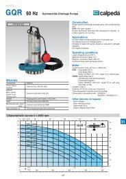
Technical appendix<br />
How to select a centrifugal pump<br />
The selection of 0 U.S. a centrifugal g.p.m. 100 pump should 150 be 200made 250 according 300 to the 350 actual<br />
40<br />
characteristics and conditions of the plant.<br />
130<br />
The required data for a correct A Ø 168selection<br />
are the following:<br />
Flow Q<br />
Quantity of fluid delivered by the pump in the unit of time, generally expressed<br />
in m3 35<br />
71<br />
η 72%<br />
110<br />
/h.<br />
B Ø 158<br />
72<br />
H m<br />
30<br />
Total manometric head Hmt<br />
69<br />
It is considered as the sum between the geometric head exsisting between 90<br />
67<br />
the fluid levels and the head loss due to frictions from the fluid 65 passage in<br />
25<br />
the pipework, into the pump and relevant hydraulic accessories. 80<br />
The expression is the following:<br />
70<br />
20<br />
3 0 m /h 20 40 60 80<br />
0 200 400 600 800 1000 1200<br />
Q<br />
Hmt = Hg + pc mt l/min fluid column<br />
0 l/s 4 8 12 16 20<br />
Hg = geometric 8 head inlet (Hga) + geometric head outlet (Hgp)<br />
A<br />
pc = sum of head loss of the plant calculated from the following data:<br />
6<br />
B<br />
- Diameter, length and material of the suction and delivery piping (see 6<br />
4<br />
table<br />
no. 2).<br />
4<br />
- Number and 2type<br />
of elbows in the piping and hydraulic accessories 2 such<br />
as foot valves, gate valves, non-return valves and strainers etc. (see<br />
0<br />
0<br />
table no. 1).<br />
- Type, temperature, 6 viscosity and density of the fluid (if different from that of<br />
water)<br />
15<br />
P kW<br />
NPSH m<br />
4<br />
2<br />
65<br />
67<br />
69<br />
Pay attention to the manometric suction lift Hga + pc asp, which should be<br />
5<br />
compared with 0the<br />
suction capability of the pump.<br />
0<br />
72.019<br />
0 3 Q m /h 20 40 60 80<br />
This suction capability or NPSHr is defined as net positve suction head and its<br />
value is obtained from a curve in accordance with the flow.<br />
0<br />
0 3 Q m /h 10 20 30 40 50<br />
0<br />
72.020<br />
60<br />
For this purpose, 0 U.S. once g.p.m. the 50 pump has 100 been selected 150 according 200 to 250 the required flow and 0 U.S. head, g.p.m. where 100possible 150 at 200 the middle 250 of 300 the curve, 350 check the<br />
following simplified 90 formula:<br />
70<br />
A Ø 250<br />
45<br />
C<br />
10 mt ± Hga - pc asp. > NPSH required + 0.5 mt<br />
80<br />
Hga is the difference in B Ø height 230 between the free surface of the water, and 240 its value is negative if the pump is installed above the free water 57 surface.<br />
pc asp is the 70sum<br />
of the remaining distributed (piping) and concentrate (valves, bends, 50 etc.) suction E Ø 190head<br />
loss<br />
55<br />
H m<br />
C Ø 217<br />
If the final result is negative, it is often possible to adjust flow via a gate valve on the delivery side, in order to restore correct pump operating 140 condi-<br />
60<br />
200<br />
40<br />
tions, without cavitation.<br />
For fluid temperatures 50 higher than the average of about 20°C, the pumps loose their suction 30 capability.<br />
160<br />
Such changes, referred to pumps with suction capability of 7 meter at normal temperature, are shown on table no. 3.<br />
CHARACTERISTIC DATA OF THE PUMPS<br />
Once the flow (Q) and total manometric head of the installation (Hmt) are established, the pump absorbed power N should be calculated through the<br />
following formula:<br />
N = Q x H x A<br />
C<br />
B 20<br />
D<br />
20<br />
C<br />
E<br />
10<br />
10<br />
in kW<br />
10<br />
10<br />
367 x p where:<br />
P kW<br />
Q = Flow in m3/h<br />
H = Head in mt<br />
= Fluid density (water = 1 kg/dm3 6<br />
4<br />
)<br />
p = Pump efficiency (Ex. Pump efficiency 68% = ➩ p = 0.68)<br />
NPSH m<br />
The pumps are 0normally<br />
connected to electric motors, which operate at 2900 0 rpm with 2-pole 0 motors at 50Hz, or at 1450 rpm with 4-pole motors at 50Hz. 0<br />
72.021<br />
72.036<br />
However, they can 0 3<br />
run at 10any<br />
other 20 speed 30 within the 40limits<br />
of 50 design. 60<br />
0 3<br />
Q m /h<br />
Q m /h 20 30 40 50 60 70 80 90<br />
Therefore, when changing the number of revolutions, the pump performance will change according to the following rules:<br />
The flow in proportion to the number of revolutions: Q2 = Q1 x<br />
The head, in proportion to the square of the number of revolutions: H2 = H1 x ( ) 2<br />
The absorbed power, in proportion to the cube of the number of revolutions: N2 = N1 x ( ) 3<br />
71<br />
120<br />
100<br />
10<br />
8<br />
10<br />
5<br />
H ft<br />
P HP<br />
NPSH ft<br />
60<br />
50<br />
40<br />
0 U.S. g.p.m. 50 100 150 200 250<br />
65<br />
64 120<br />
30<br />
100<br />
3 0<br />
Q m /h<br />
0 l/min<br />
10<br />
200<br />
20<br />
400<br />
30<br />
600<br />
40 50<br />
800<br />
60<br />
1000<br />
0 l/s 2 4 6 8 10 12 14 16<br />
12<br />
10<br />
A 15<br />
8<br />
6<br />
B<br />
10<br />
4<br />
2<br />
0<br />
6<br />
4<br />
2<br />
A Ø 200<br />
B Ø 188<br />
50<br />
55<br />
60 62 64 65<br />
50 140<br />
80<br />
40<br />
3 0<br />
Q m /h<br />
0 l/min<br />
10<br />
200<br />
20<br />
400<br />
30<br />
600<br />
40 50<br />
800<br />
60<br />
1000<br />
20<br />
3 0<br />
Q m /h<br />
0 l/min<br />
20 30<br />
500<br />
40 50 60<br />
1000<br />
70 80 90<br />
1500<br />
0 l/s 2 4 6 8 10 12 14 16<br />
20<br />
0<br />
2<br />
50<br />
53<br />
NM 50/16<br />
55<br />
NM 50/25<br />
η 59%<br />
57<br />
n2<br />
n1<br />
280<br />
260<br />
220<br />
180<br />
26<br />
0<br />
20<br />
15<br />
10<br />
5<br />
H ft<br />
P HP<br />
NPSH ft<br />
379<br />
n2<br />
n1<br />
H m<br />
P kW<br />
NPSH m<br />
H m<br />
P kW<br />
NPSH m<br />
60<br />
0 l/s<br />
10 20<br />
20<br />
0<br />
8<br />
6<br />
4<br />
2<br />
n2<br />
n1<br />
Ø 218<br />
D Ø 203.5<br />
52 55<br />
57 59 61 η 62%<br />
NM 50/20<br />
61<br />
η 66%<br />
NM 50M<br />
59<br />
52<br />
180<br />
160<br />
140<br />
5<br />
0<br />
20<br />
15<br />
10<br />
220<br />
200<br />
180<br />
160<br />
120<br />
100<br />
26<br />
0<br />
25<br />
20<br />
15<br />
10<br />
5<br />
H ft<br />
P HP<br />
NPSH ft<br />
H ft<br />
P HP<br />
NPSH ft<br />
49