EuMC_2011 - iitk.ac.in - Indian Institute of Technology Kanpur
EuMC_2011 - iitk.ac.in - Indian Institute of Technology Kanpur
EuMC_2011 - iitk.ac.in - Indian Institute of Technology Kanpur

You also want an ePaper? Increase the reach of your titles
YUMPU automatically turns print PDFs into web optimized ePapers that Google loves.
Coaxial Fed Half-Split Multilayer Cyl<strong>in</strong>drical<br />
Dielectric Resonator Antenna for Wideband<br />
Applications<br />
Raghvendra Kumar Chaudhary 1 , Gautam Kumar S<strong>in</strong>gh 2 , Kumar Vaibhav Srivastava 3 and Animesh Biswas 4 .<br />
Department <strong>of</strong> Electrical Eng<strong>in</strong>eer<strong>in</strong>g<br />
<strong>Indian</strong> <strong>Institute</strong> <strong>of</strong> <strong>Technology</strong> <strong>Kanpur</strong><br />
<strong>Kanpur</strong>, Uttar Pradesh, INDIA, 208016<br />
Phone No: +91-512-2597319<br />
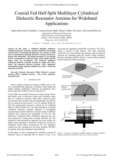
Abstr<strong>ac</strong>t—In this paper a wideband half-split multilayer<br />
cyl<strong>in</strong>drical dielectric resonator antenna (MCDRA) fed through<br />
coaxial probe is developed and discussed. The concept <strong>of</strong> multi<br />
layers is <strong>in</strong>troduced <strong>in</strong> half-split dielectric resonator antenna for<br />
gett<strong>in</strong>g wide bandwidth. The design parameters <strong>of</strong> an antenna<br />
such as arrangement <strong>of</strong> dielectric layers, probe height and DR<br />
aspect ratio are <strong>in</strong>vestigated. The proposed multilayer<br />
cyl<strong>in</strong>drical dielectric resonator antenna is excited with TM 21δ<br />
mode. The proposed structure provides ~60% impedance<br />
bandwidth for <strong>in</strong>put reflection coefficient (S 11) below -10 dB with<br />
total ga<strong>in</strong> <strong>of</strong> 6.09 dB.<br />
Keywords- Dielectric Resonators (DRs), Dielectric resonator<br />
antenna (DRA), wideband antenna, TM 21δ mode, impedance<br />
bandwidth, ga<strong>in</strong>.<br />
I. INTRODUCTION<br />
Due to number <strong>of</strong> attr<strong>ac</strong>tive features <strong>of</strong> DRA such as low<br />
loss, wide-bandwidth, high ga<strong>in</strong>, versatility <strong>in</strong> their shape and<br />
simple feed<strong>in</strong>g mechanism, numerous <strong>in</strong>vestigations have<br />
been carried out on DRAs <strong>in</strong> last two decades [1].<br />
In past, DRs were usually treated as an energy storage device<br />
and ma<strong>in</strong>ly used <strong>in</strong> microwave filters and oscillators rather<br />
than as a radiator or antenna. When DR is pl<strong>ac</strong>ed <strong>in</strong> open<br />
environment then Q-f<strong>ac</strong>tor reduced significantly and DR <strong>ac</strong>t<br />
like an antenna because power is lost <strong>in</strong> radiated fields [2].<br />
The first experimental research is carried out for wideband<br />
DRA <strong>in</strong> 1989 by Kishk et al.. The <strong>in</strong>put impedance <strong>of</strong> st<strong>ac</strong>ked<br />
cyl<strong>in</strong>drical dielectric resonator antennas is <strong>in</strong>vestigated<br />
experimentally and the dielectric resonators made <strong>of</strong> different<br />
materials have <strong>ac</strong>hieved the bandwidth <strong>of</strong> 25% [3]. The<br />
Multilayer Cyl<strong>in</strong>drical DRA (MCDRA) appro<strong>ac</strong>h has also<br />
been reported by commercially available materials [4]. The<br />
multilayer multi-permittivity appro<strong>ac</strong>h has been studied for<br />
higher mode separation <strong>in</strong> dielectric resonator <strong>in</strong> microwave<br />
<strong>in</strong>tegrated circuit (MIC) environment [5]. The multilayer<br />
concept has also <strong>in</strong>troduced <strong>in</strong> the three elements MCDRA<br />
for gett<strong>in</strong>g wide <strong>in</strong>put impedance bandwidth [6].<br />
In this paper, we have <strong>in</strong>troduced the multilayer concept <strong>of</strong><br />
dielectric layers <strong>in</strong> half-split DR as shown <strong>in</strong> Fig. 1 for<br />
Proceed<strong>in</strong>gs <strong>of</strong> the 41st European Microwave Conference<br />
{ 1 raghav, 2 s<strong>in</strong>ghgk, 3 kvs, and 4 abiswas}@<strong>iitk</strong>.<strong>ac</strong>.<strong>in</strong><br />
<strong>in</strong>creas<strong>in</strong>g the impedance bandwidth <strong>of</strong> antenna. The TM21δ<br />
mode is excited <strong>in</strong> DR antenna. The <strong>in</strong>put reflection<br />
coefficient (S11) and absolute ga<strong>in</strong> patterns and <strong>of</strong> proposed<br />
structure are simulated us<strong>in</strong>g the Ans<strong>of</strong>t’s High Frequency<br />
Structure Simulator (HFSS), which is a f<strong>in</strong>ite-element method<br />
based commercial s<strong>of</strong>tware p<strong>ac</strong>kage.<br />
Multilayer<br />
half-split<br />
cyl<strong>in</strong>drical DRA<br />
Coaxial<br />
Probe<br />
Figure 1. Geometry <strong>of</strong> proposed wideband half-spilt multilayer dielectric<br />
resonator antenna (a). 3D view (b). top view (c). Front view (XX’).<br />
(a)<br />
ß<br />
(b)<br />
(c)<br />
(a)<br />
X X’<br />
978-2-87487-022-4 © <strong>2011</strong> EuMA 1015<br />
10-13 October <strong>2011</strong>, Manchester, UK<br />
a
II. THEORY FOR CONVENTIONAL HALF-SPLIT DRA<br />
For the simple half-split dielectric resonator antenna with<br />
sector angle β, radius a and height h, the z-component <strong>of</strong><br />
z<br />
electric field distribution for the TM vpm+<br />
δ mode <strong>in</strong>side the<br />
DRA is given by cavity model analysis [7, 8]<br />
( ) cos ( φ ) cos(<br />
)<br />
vpm<br />
z v r z<br />
E = AJ k r v k z<br />
(1)<br />
for 0 ≤ r ≤ a,<br />
0 ≤φ≤ β , 0 ≤ z ≤ h . In the above expression v<br />
is a positive real number, depends upon the boundary<br />
conditions while p, m are positive <strong>in</strong>tegers and k r , kz are the<br />
wave numbers. The function J v denotes the vth-order Bessel<br />
function <strong>of</strong> first k<strong>in</strong>d and A is complex constant depends upon<br />
the geometry and feed.<br />
The resonant frequency <strong>of</strong> a mode f vpm is given as [7, 8]<br />
c<br />
f = k + k<br />
(2)<br />
vpm<br />
2 2<br />
r<br />
2πaεr<br />
r z<br />
X vp (2m + 1) π<br />
where c is the velocity <strong>of</strong> light, kr<br />
= , kz<br />
= are<br />
a 2h<br />
wave numbers and X vp is the root <strong>of</strong> char<strong>ac</strong>teristic equations.<br />
For a sector DRA with sector angle β = π with open sector<br />
f<strong>ac</strong>es, the fundamental resonant mode is TM11δ and the next<br />
higher resonant mode is TM 21δ<br />
[9]. The fr<strong>ac</strong>tional impedance<br />
bandwidth <strong>of</strong> a DRA can be calculated by<br />
Δf<br />
Impedance Bandwidth ( BW ) = (3)<br />
f<br />
where Δ f and f r are absolute bandwidth and resonant<br />
frequency respectively.<br />
III. ANTENNA CONFIGURATION<br />
Fig. 1 shows the proposed half-spilt multilayer cyl<strong>in</strong>drical<br />
dielectric resonator antenna where the height <strong>of</strong> layers are<br />
h1, h2 and h3 and their dielectric constant are εr1, εr2 and εr3<br />
respectively. The radius <strong>of</strong> e<strong>ac</strong>h layer is a. The MCDRA is<br />
pl<strong>ac</strong>ed on metallic ground plane and this arrangement is<br />
excited with TM21δ mode by coaxial probe <strong>of</strong> height hp and<br />
radius ro.<br />
A. Dielectric Layer Optimization<br />
The MCDRA consists <strong>of</strong> several layers hav<strong>in</strong>g different<br />
heights and pemittivitties, but they need to be arranged <strong>in</strong><br />
some particular manner for wide impedance bandwidth. The<br />
different arragnemnts <strong>of</strong> MCDRA have been simulated and it<br />
has been found that if layers are arranged <strong>in</strong> ascend<strong>in</strong>g order<br />
<strong>of</strong> their permittivttives, the bandwidth can be improved<br />
sign<strong>in</strong>icantly. It is also obvious that if lower permittivity layer<br />
is on bottom side the less amount <strong>of</strong> energy will be conf<strong>in</strong>ed<br />
r<br />
<strong>in</strong> bottom layer and effect <strong>of</strong> ground plane to the fields stored<br />
<strong>in</strong> that layer will be m<strong>in</strong>imal. However, if the permittivity <strong>of</strong><br />
top layer is higher, most <strong>of</strong> the energy will conf<strong>in</strong>ed <strong>in</strong> top<br />
layer and will be and less <strong>in</strong>fluenced by ground plane.<br />
The optimized dimensions for half-split multilayer cyl<strong>in</strong>drical<br />
DRA are obta<strong>in</strong>ed as the radius <strong>of</strong> e<strong>ac</strong>h dielectric layer (a) =<br />
20 mm, height <strong>of</strong> bottom layer (h1) = 3.81 mm, height <strong>of</strong><br />
middle layer (h2) = 3.17 mm and height <strong>of</strong> top layer (h3) =<br />
3.81 mm. The dielectric materials are choosen as from<br />
commercailly available materials Polyflon Polyguide ( ε r =<br />
2.32), Roger RT/Duroid 6006 ( ε r = 6.15), Roger RT/Duroid 6010<br />
( ε r = 10.2).<br />
TABLE I. IMPEDANCE BANDWDITH OF DIFFERENT DIELECTRIC LAYER<br />
ARRANGEMENT<br />
[a = 20 mm, h1 = 3.81 mm, h2 = 3.17 mm, h3 = 3.81 mm, ro = 0.55 mm.]<br />
Bottom<br />
Layer (εr1)<br />
Middle<br />
Layer (εr2)<br />
Top Layer<br />
(εr3)<br />
Probe<br />
height (hp)<br />
BW (%)<br />
6.15 10.2 2.32 10.6 mm 23.1<br />
10.2 6.15 2.32 8.2 mm 12.3<br />
6.15 2.32 10.2 8.8 mm 51.7<br />
2.32 6.15 10.2 7.7 mm 60.0<br />
10.2 2.32 6.15 10.4 mm 35.5<br />
2.32 10.2 6.15 6.4 mm 50.2<br />
All the possible dielectric layer arrangement for half-split<br />
MCDRA and probe height for different arrangement<br />
corresponds to its optimal height for maximum bandwidth is<br />
listed <strong>in</strong> Table I. So the optimal arrangement for three<br />
dielectric layers from bottom to top are Polyflon Polyguide<br />
( ε r1<br />
= 2.32), Roger RT/Duroid 6006 ( ε r 2 = 6.15), Roger<br />
RT/Duroid 6010 ( ε r3<br />
= 10.2). Us<strong>in</strong>g this comb<strong>in</strong>ation wide<br />
impedance bandwidth can be obta<strong>in</strong>ed.<br />
1016<br />
By the simulations, it is clear that the impedance bandwidth<br />
will be high when the top layer hav<strong>in</strong>g high dielectric<br />
constant <strong>in</strong> comparision with other layers. For multilayer<br />
DRA, lower dielectric constant section improves the<br />
bandwidth and higher dielectric constant section helps to<br />
lower the resonant frequency and vice-versa [2].<br />
B. Probe Height Optimization<br />
Now for study<strong>in</strong>g the char<strong>ac</strong>teristics <strong>of</strong> proposed half-spilt<br />
multilayer dielectric resonator antenna, the study has been<br />
performed for different probe height for good <strong>in</strong>put<br />
impedance match<strong>in</strong>g.<br />
Fig. 2 shows the comparision <strong>of</strong> <strong>in</strong>put reflection c<strong>of</strong>fecient<br />
(S11) for proposed half-spilt multilayer cyl<strong>in</strong>drical dielectric<br />
resonator antenna with different probe heights. From the Fig.<br />
2, it is clear that the wideband response and good match<strong>in</strong>g<br />
occurs at probe height <strong>of</strong> 7.7 mm.
Reflection Coefficient (S 11 ) dB<br />
-30<br />
hp = 7.1 mm<br />
hp = 7.3 mm<br />
hp = 7.5 mm<br />
-40<br />
hp = 7.7 mm<br />
hp = 7.9 mm<br />
hp = 8.1 mm<br />
-50<br />
3 4 5 6<br />
Frequecny (GHz)<br />
7 8<br />
Figure 2. Simulated reflection coefficient (S11) <strong>of</strong> half-spilt multilayer<br />
dielectric resonator antenna for different probe heights.<br />
IV. RESULTS<br />
The design parameters <strong>of</strong> half-spilt multilayer cyl<strong>in</strong>drical<br />
dielectric resonator antenna are a = 20 mm, h1 = 3.81 mm, h2<br />
= 3.17 mm, h3 = 3.81 mm, ro = 0.55 mm, and hp = 7.7 mm.<br />
The <strong>in</strong>put reflection coefficient (S11) below -10 dB is obta<strong>in</strong>ed<br />
<strong>in</strong> the frequency range <strong>of</strong> 4.14 to 6.94 GHz. The resonance<br />
frequency is 4.68 GHz and correspond<strong>in</strong>gly the percentage<br />
impedance bandwidth is ~60% as shown <strong>in</strong> Fig. 3.<br />
Reflection Coefficient (S 11 ) dB<br />
0<br />
-10<br />
-20<br />
0<br />
-10<br />
-20<br />
-30<br />
-40<br />
4.14 GHz<br />
4.68 GHz<br />
6.94 GHz<br />
-50<br />
3 4 5 6<br />
Frequecny (GHz)<br />
7 8 9<br />
Figure 3. Reflection coefficient (S11) <strong>of</strong> half-spilt multilayer dielectric<br />
resonator antenna. [a = 20 mm, h1 = 3.81 mm, h2 = 3.17 mm, h3 = 3.81 mm,<br />
ro = 0.55 mm, εr1 = 2.32, εr2 = 6.15, εr3 = 10.2 and hp = 7.7 mm]<br />
The VSWR <strong>of</strong> half-split multilayer cyl<strong>in</strong>drical DRA is shown<br />
<strong>in</strong> Fig. 4. The VSWR < 2 is observed <strong>in</strong> the frequency range<br />
4.14 GHz to 6.94 GHz.<br />
The <strong>in</strong>put impedance <strong>of</strong> the antenna is shown <strong>in</strong> Fig. 5, which<br />
<strong>in</strong>dicates good match<strong>in</strong>g with the coaxial feed l<strong>in</strong>e at<br />
resonance frequency 4.68 GHz. The real part <strong>of</strong> <strong>in</strong>put<br />
impedance is 50.47 ohm and imag<strong>in</strong>ary part is 0.46 ohm at<br />
resonance frequency.<br />
1017<br />
VSWR<br />
3 4 5 6 7 8 9<br />
Frequecny (GHz)<br />
Figure 4. VSWR for half-spilt multilayer dielectric resonator antenna.<br />
R <strong>in</strong> , X <strong>in</strong> (Ohm)<br />
Figure 5. Input impedance (real and imag<strong>in</strong>ary part) <strong>of</strong> half-spilt multilayer<br />
dielectric resonator antenna.<br />
0<br />
Ga<strong>in</strong> (dB)<br />
30<br />
25<br />
20<br />
15<br />
10<br />
5<br />
0<br />
150<br />
125<br />
100<br />
75<br />
50<br />
25<br />
5<br />
0<br />
-5<br />
-10<br />
-15<br />
270<br />
-15<br />
-10<br />
-5<br />
0<br />
5<br />
0<br />
-25<br />
-50<br />
-75<br />
300<br />
240<br />
VSWR < 2 for frequency range 4.14 GHz to 6.94 GHz<br />
at 4.68 GHz<br />
R <strong>in</strong> = 50.47 ohm<br />
X <strong>in</strong> = 0.46 ohm<br />
3 4 5 6<br />
Frequency (GHz)<br />
7 8 9<br />
330<br />
210<br />
180<br />
30<br />
150<br />
60<br />
120<br />
Figure 6. Absoulte ga<strong>in</strong> pattern (at 4.68 GHz) <strong>in</strong> x-z plane for half-spilt<br />
multilayer dielectric resonator antenna.<br />
Fig. 6 and Fig.7 shows the Absoulte ga<strong>in</strong> pattern <strong>of</strong> half-split<br />
multilayer cyl<strong>in</strong>drical DRA for the far field <strong>in</strong> the two<br />
pr<strong>in</strong>cipal planes, i.e. absolute ga<strong>in</strong> versus θ for Φ = 0 o (x-z<br />
90
plane) and absolute ga<strong>in</strong> pattern versus θ for Φ = 90 o (y-z<br />
plane) at resonan<strong>ac</strong>e frequency <strong>of</strong> 4.68 GHz.<br />
Ga<strong>in</strong> (dB)<br />
10<br />
5<br />
0<br />
-5<br />
-10<br />
300<br />
-15<br />
270<br />
-10<br />
-5<br />
0<br />
240<br />
5<br />
10<br />
330<br />
210<br />
0<br />
180<br />
30<br />
150<br />
60<br />
120<br />
Figure 7. Absoulte ga<strong>in</strong> pattern (at 4.68 GHz) <strong>in</strong> y-z plane for half-spilt<br />
multilayer dielectric resonator antenna.<br />
Figure 8. Absoulte ga<strong>in</strong> <strong>in</strong> 3D (at 4.68 GHz) for half-spilt multilayer<br />
dielectric resonator antenna.<br />
The far field, 3-D view <strong>of</strong> total ga<strong>in</strong> pattern <strong>of</strong> proposed<br />
struture is shown <strong>in</strong> Fig. 8, which shows the maximum ga<strong>in</strong><br />
<strong>of</strong> 6.09 dB at the resoan<strong>ac</strong>e frequency <strong>of</strong> 4.68 GHz.<br />
V. CONCLUSION<br />
A half-split multilayer cyl<strong>in</strong>drical dielectric resonator antenna<br />
mounted on f<strong>in</strong>ite ground plane has been <strong>in</strong>vestigated. It is<br />
simply excited by coaxial probe with TM21δ mode. The<br />
concept <strong>of</strong> st<strong>ac</strong>k<strong>in</strong>g the dielectric layers <strong>in</strong> half-split DRA is<br />
proposed <strong>in</strong> this paper for gett<strong>in</strong>g the wide <strong>in</strong>put impedance<br />
bandwidth. The <strong>in</strong>put reflection coefficient (S11) curve shows<br />
~60% impedance bandwidth (S11 < ─10dB) with good<br />
radiation pattern which is stable <strong>in</strong> the passband. The<br />
90<br />
1018<br />
maximum absolute ga<strong>in</strong> <strong>of</strong> proposed antenna is 6.09 dB at<br />
4.68 GHz. The proposed antenna is suitable for C-band<br />
application like <strong>in</strong> WiMAX applications.<br />
REFERENCES<br />
[1] A. Petosa, A. Ittipibo, Y. M. MAntar, D. Roscoe and M. Cuh<strong>ac</strong>i,<br />
“Recent Advances <strong>in</strong> Dielectric-Resonator Antenna <strong>Technology</strong>,” IEEE<br />
Antennas Propogation Magaz<strong>in</strong>e, vol. 40, no. 3, pp. 35 – 48, June 1998.<br />
[2] R. K. Mongia and P. Bhartia, "Dielectric resonator antennas—A review<br />
and general design relations for resonant frequency and bandwidth",<br />
International Journal <strong>of</strong> Microwave and Millimeter-Wave Computer<br />
Aided Eng<strong>in</strong>eer<strong>in</strong>g, vol. 4, pp. 230–247, July 1994.<br />
[3] A.A. Kishk, B. Ahn, and D. Kajfez, "Broadband st<strong>ac</strong>ked dielectric<br />
resonator antennas", IET, Electron Letters vol. 25, pp 1232–1233,<br />
Auguest 1989.<br />
[4] W. Huang and A.A. Kishk, “Comp<strong>ac</strong>t wideband multi-layer cyl<strong>in</strong>drical<br />
dielectric resonator antennas”, IET Microw. Antennas Propagation, vol.<br />
1, pp. 998-1005,Oct. 2007.<br />
[5] Raghvendra Kumar Chaudhary, Vishwa V. Mishra, Kumar Vaibhav<br />
Srivastava and Animesh Biswas, “Multi-layer Multi-permittivity<br />
Dielectric Resonator: A New Appro<strong>ac</strong>h for Improved Spurious free<br />
w<strong>in</strong>dow”, <strong>in</strong> Proceed<strong>in</strong>gs <strong>of</strong> <strong>EuMC</strong>-2010, pp. 1194-1197 Paris, France,<br />
Oct. 2010.<br />
[6] Raghvendra Kumar Chaudhary, Kumar Vaibhav Srivastava and<br />
Animesh Biswas, “An Investigation on Three Element Multilayer<br />
Cyl<strong>in</strong>drical Dielectric Resonator Antenna”, IEEE Asia-P<strong>ac</strong>ific<br />
Conference on Applied Electromagnetics (APACE) ), 09 Nov. - 11<br />
Nov., 2010 <strong>in</strong> Port Dickson, Malaysia.<br />
[7] S. A. Long, M. W. McAllister, and L. C. Shen, “The resonant<br />
cyl<strong>in</strong>drical dielectric cavity antenna”, IEEE Trans. Antennas Propagat.,<br />
vol. AP-31, no. 3, pp. 406–412, March 1983.<br />
[8] Matthew T. K. Tam and Ross D. Murch, “Comp<strong>ac</strong>t Circular Sector and<br />
Annular Sector Dielectric Resonator Antennas”, IEEE Tranns<strong>ac</strong>tions<br />
on Antennas and Propagation, vol. 47, no. 5, pp. 837 – 842, May 1999.<br />
[9] K. M. Luk and K. W. Leung, “Dielectric Resonator Antenna”, Research<br />
Studies Press Ltd. Baldock, Hertfordshire, England, pp. 274-275, April<br />
2003.