Instruction Manual - Magnetrol International
Instruction Manual - Magnetrol International
Instruction Manual - Magnetrol International

You also want an ePaper? Increase the reach of your titles
YUMPU automatically turns print PDFs into web optimized ePapers that Google loves.
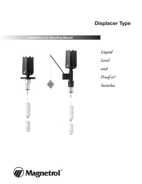
Installation and Operating <strong>Manual</strong><br />
Displacer Type<br />
Liquid<br />
Level<br />
and<br />
Proof-er ®<br />
Switches
Read this <strong>Manual</strong> Before Installing<br />
This manual provides information on the External Cage<br />
Displacer Liquid Level Switch. It is important that all<br />
instructions are read carefully and followed in sequence.<br />
Detailed instructions are included in the Installation section<br />
of this manual.<br />
Conventions Used in this <strong>Manual</strong><br />
Certain conventions are used in this manual to convey<br />
specific types of information. General technical material,<br />
support data, and safety information are presented in<br />
narrative form. The following styles are used for notes,<br />
cautions, and warnings.<br />
Notes<br />
Notes contain information that augments or clarifies<br />
an operating step. Notes do not normally contain<br />
actions. They follow the procedural steps to which<br />
they refer.<br />
Cautions<br />
Cautions alert the technician to special conditions that<br />
could injure personnel, damage equipment, or reduce<br />
a component’s mechanical integrity. Cautions are also<br />
used to alert the technician to unsafe practices or the<br />
need for special protective equipment or specific<br />
materials. In this manual, a caution box indicates a<br />
potentially hazardous situation which, if not avoided,<br />
may result in minor or moderate injury.<br />
Warnings<br />
Warnings identify potentially dangerous situations or<br />
serious hazards. In this manual, a warning indicates an<br />
imminently hazardous situation which, if not avoided,<br />
could result in serious injury or death.<br />
Safety Messages<br />
Follow all standard industry procedures for servicing electrical<br />
equipment when working with or around high<br />
voltage. Always shut off the power supply before touching<br />
any components.<br />
WARNING! Explosion hazard. Do not connect or disconnect<br />
equipment unless power has been switched off or<br />
the area is known to be non-hazardous.<br />
Low Voltage Directive<br />
For use in Installation Category II, Pollution Degree 2. If<br />
equipment is used in a manner not specified by the<br />
manufacturer, protection provided by the equipment<br />
may be impaired.<br />
Notice of Trademark, Copyright, and Limitations<br />
<strong>Magnetrol</strong> & <strong>Magnetrol</strong> logotype and Proof-er are<br />
registered trademarks of <strong>Magnetrol</strong> <strong>International</strong>.<br />
Copyright © 2010 <strong>Magnetrol</strong> <strong>International</strong>,<br />
Incorporated. All rights reserved.<br />
<strong>Magnetrol</strong> reserves the right to make changes to the<br />
product described in this manual at any time without<br />
notice. <strong>Magnetrol</strong> makes no warranty with respect to the<br />
accuracy of the information in this manual.<br />
Warranty<br />
All <strong>Magnetrol</strong> mechanical level and flow controls are<br />
warranted free of defects in materials or workmanship for<br />
five full years from the date of original factory shipment.<br />
If returned within the warranty period; and, upon factory<br />
inspection of the control, the cause of the claim is<br />
determined to be covered under the warranty; then,<br />
<strong>Magnetrol</strong> will repair or replace the control at no cost to<br />
the purchaser (or owner) other than transportation.<br />
<strong>Magnetrol</strong> shall not be liable for misapplication, labor<br />
claims, direct or consequential damage or expense arising<br />
from the installation or use of equipment. There are no<br />
other warranties expressed or implied, except special<br />
written warranties covering some <strong>Magnetrol</strong> products.<br />
Quality Assurance<br />
The quality assurance system in place at <strong>Magnetrol</strong> guarantees<br />
the highest level of quality throughout the company.<br />
<strong>Magnetrol</strong> is committed to providing full customer satisfaction<br />
both in quality products and quality service.<br />
<strong>Magnetrol</strong>’s quality assurance system<br />
is registered to ISO 9001 affirming its<br />
commitment to known international<br />
quality standards providing the<br />
strongest assurance of product/service<br />
quality available.<br />
45-610 Displacer Type Liquid Level Switches and Proof-er ® Switches
Table of Contents<br />
Displacer Type<br />
Liquid Level and Proof-er ® Switches<br />
1.0 Introduction<br />
1.1 Principle of Operation...........................................4<br />
1.1.1 Displacer Controls......................................4<br />
1.2 Operating Cycle ....................................................4<br />
1.3 Operating Cycle — Proof-er Control Option........4<br />
2.0 Installation<br />
2.1 Unpacking.............................................................5<br />
2.2 Mounting ..............................................................5<br />
2.3 Wiring...................................................................6<br />
3.0 Preventive Maintenance<br />
3.1 What to do............................................................8<br />
3.1.1 Keep control clean ......................................8<br />
3.1.2 Inspect switch mechanisms, terminals, and<br />
connections monthly ..................................8<br />
3.2 What to avoid .......................................................9<br />
4.0 Reference Information<br />
4.1 Troubleshooting...................................................10<br />
4.1.1 Check switch mechanism..........................10<br />
4.1.2 Test control’s performance ........................11<br />
4.1.3 Proof-er ....................................................12<br />
4.2 Agency Approvals ................................................12<br />
4.3 Specifications.......................................................13<br />
45-610 Displacer Type Liquid Level Switches and Proof-er ® Switches<br />
4.3.1 Basic Electrical Ratings ............................13<br />
4.3.2 Pressure/Temperature Ratings ..................13<br />
4.3.3 Model A10 Dimensional Data and<br />
Actuating Levels.......................................14<br />
4.3.4 Model A15 Dimensional and<br />
Actuating Levels.......................................15<br />
4.3.5 Model B10 Dimensional Data.................16<br />
4.3.6 Model B10 Actuating Levels....................17<br />
4.3.7 Model B15 Dimensional Data.................24<br />
4.3.8 Model B15 Actuating Levels....................25<br />
4.3.9 Model C10 Dimensional Data ................26<br />
4.3.10 Model C10 Actuating Levels ...................27<br />
4.3.11 Model C15 Dimensional Data ................30<br />
4.3.12 Model C15 Actuating Levels ...................31<br />
4.3.13 Proof-er Dimensional Data......................31<br />
4.3.14 Proof-er Replacement Parts......................32<br />
4.4 Replacement Parts ...............................................33<br />
4.4.1 Displacer Replacement Parts.....................33<br />
4.5 Model Numbers ..................................................34<br />
4.5.1 A10 & A15 Single Switch Models ............34<br />
4.5.2 B10 & B15 Dual Switch Models..............36<br />
4.5.3 C10 & C15 Triple Switch Models ............38
1<br />
2<br />
4 3<br />
2<br />
1<br />
Figure 1<br />
Switch position<br />
on rising level<br />
1<br />
2<br />
4 3<br />
2<br />
1<br />
Figure 2<br />
Switch position<br />
on falling level<br />
5<br />
5<br />
3<br />
3<br />
1.0 Introduction<br />
Displacement type level switches offer the industrial user a wide<br />
choice of alarm and control configurations. These units utilize<br />
simple buoyancy principle and are well suited for simple or<br />
complex applications.<br />
1.1 Principle of Operation<br />
1.1.1 Displacer Controls<br />
The design of displacer operated level switches is based upon<br />
the principle that a magnetic field will not be affected by nonmagnetic<br />
materials such as 316 stainless steel. In this case, the<br />
displacer moves a magnetic attraction sleeve within a non-magnetic<br />
enclosing tube and actuates a magnetic switch mechanism.<br />
The enclosing tube provides a pressure seal to the chamber and,<br />
therefore, to the process.<br />
1.2 Operating Cycle<br />
A spring is loaded with a weighted displacer ➀ which is heavier<br />
than the liquid. Immersion of the displacers caused by rising<br />
liquid level imparts buoyancy forces on the displacer allowing the<br />
spring to compress. The attraction sleeve ➁ attached to the spring,<br />
moves upward into the field of a permanent magnet ➂. The<br />
movement of the magnet toward the sleeve causes the switch ➃ to<br />
actuate. A non-magnetic barrier tube ➄ provides a static pressure<br />
boundary between the switch mechanism and the displacer assembly.<br />
As the liquid level falls, the displacer lowers, causing the spring<br />
to extend, and moving the attraction sleeve out of the magnetic<br />
field of the switch mechanism. This allows the switch to again<br />
change position and to break or make. See Figures 1 and 2.<br />
1.3 Floating Roof Detection<br />
The spring is loaded with a displacer weight suspended from a<br />
stainless steel cable. As the floating roof rises, the weight is lifted<br />
by the roof allowing the spring to compress, the attraction<br />
sleeve to move upward into the field of the switch magnet and<br />
the switch to actuate. As the roof lowers, the weight again hangs<br />
free causing the spring to extend, the sleeve to move downward<br />
and the switch to reset. The displacers are usually fabricated<br />
from ductile metals, such as brass, to prevent sparking when the<br />
displacer makes contact with the roof.<br />
1.4 Operating Cycle — Proof-er Control Option<br />
The purpose of the Proof-er is to check the operation of a<br />
displacer control without having to raise the level in the tank.<br />
This is accomplished by pulling downward on the Proof-er<br />
cable. This causes the spring loaded lever arm to lift the switch<br />
actuator, simulating a high or high–high level condition.<br />
When the cable is released, the Proof-er returns the actuator to<br />
its original position resuming normal operation.<br />
4 45-610 Displacer Type Liquid Level Switches and Proof-er ® Switches
2.0 Installation<br />
Caution: If equipment is used in a manner not specified by manufacturer,<br />
protection provided by equipment may be<br />
impaired.<br />
2.1 Unpacking<br />
Top mounting displacer units are shipped from the factory<br />
with the displacer and cable assembly removed from the<br />
head assembly and packed separately in the same container.<br />
Caution: If reshipping to another location, displacer assembly must<br />
again be removed from the control to prevent damage.<br />
Unpack the instrument carefully. Inspect all units for<br />
damage. Report any concealed damage to carrier within<br />
24 hours. Check the contents of the packing slip and<br />
purchase order. Check and record the serial number for<br />
future reference when ordering parts.<br />
Caution: The threaded connection link and stem protruding from<br />
the head assembly are extremely fragile. DO NOT handle<br />
or place control in a position so that any amount of force<br />
is placed on the stem. Proper operation of the control<br />
requires that the stem is not damaged or bent.<br />
Caution: Displacer spring and stem are fragile. DO NOT drop displacers<br />
into tank. Hand feed cable into position to avoid<br />
bending stem.<br />
2.2 Mounting<br />
Caution: This instrument is intended for use in Installation Category II,<br />
Pollution Degree 2.<br />
Adjust the displacers on the displacer cable for the desired<br />
switch actuating levels (instruction tag is attached to<br />
cable). Screw displacer cable fitting to threaded connection<br />
link protruding from the underside of control.<br />
Be sure there are no tubes, rods, or other obstacles in the<br />
tank or vessel to interfere with the operation of the displacers.<br />
No guides into the tank are necessary unless liquid<br />
turbulence is excessive, in which case a guide pipe or tube<br />
should be at least 1 inch larger than the displacer diameter,<br />
open at the bottom end, and with several vent holes<br />
located above the maximum high level of the liquid.<br />
Check the installation of pipe or tube to be certain it<br />
is plumb.<br />
45-610 Displacer Type Liquid Level Switches and Proof-er ® Switches 5
Screw<br />
Screw<br />
Set Screw<br />
Figure 2<br />
NEMA 4X, NEMA 4X/7/9,<br />
NEMA 4X/7/9 Group B<br />
Frame Mounting<br />
Screw<br />
Figure 3<br />
Switch Mechanism<br />
Caution: Before attaching <strong>Magnetrol</strong> control to tank or vessel, using<br />
a level, check to see that tank mounting flange is within 3°<br />
of horizontal in all directions. Proper operation of the control<br />
depends on the switch housing being plumb.<br />
For floating roof top applications, the displacer switch may<br />
be mounted via flange or threaded mounting on a bracket,<br />
catwalk, etc. or through an opening in an outer dome roof.<br />
Ensure that there are no obstacles to interfere with the<br />
operation of the displacers or weights and that there is a<br />
level surface on the roof beneath the displacer/weight.<br />
Caution: Operation of all buoyancy type level devices should be<br />
done in such a way as to minimize the action of dynamic<br />
forces on the float or displacer sensing element. Good<br />
practice for reducing the likelihood of damage to the control<br />
is to equalize pressure across the device slowly.<br />
2.3 Wiring<br />
Caution: Level controls are shipped from the factory with the<br />
enclosing tube tightened and the middle set screw, on the<br />
housing base, locked to the enclosing tube. Failure to<br />
loosen the set screw prior to repositioning the conduit<br />
connection may cause the enclosing tube to loosen,<br />
resulting in the possible leakage of the process liquid<br />
or vapor.<br />
NOTE: If control is equipped with pneumatic switch mechanism, disregard<br />
these instructions and refer to instruction bulletin on<br />
mechanism furnished for air (or gas) connections.<br />
Most switch enclosures are designed to provide 360° positioning<br />
of the conduit outlet by loosening the set screw(s)<br />
located at the bottom of the switch housing base. To rotate<br />
conduit entry:<br />
1. Loosen set screw(s) at base of switch housing. Refer to<br />
Figure 2.<br />
2. Rotate switch housing so that conduit entry is<br />
positioned as desired.<br />
3. Tighten set screws at base of housing.<br />
At the factory, terminal blocks are positioned next to the<br />
conduit entry to facilitate wiring. If repositioning of the<br />
switch mechanisms is desired:<br />
1. Unscrew and remove switch housing cover. The threads<br />
have been lubricated to facilitate removal.<br />
2. Loosen the frame mounting screw on each switch mechanism.<br />
Refer to Figure 3.<br />
3. Carefully rotate the baffle plate and all switch mechanisms<br />
together until the terminal blocks are in the desired position.<br />
NOTE: On dual and triple stage controls the correct spacing of the<br />
mechanisms is maintained using brackets that connect the<br />
mechanisms. Take care when rotating the baffle plate and<br />
mechanisms to rotate them as a unit and not one at a time.<br />
This will ensure that the brackets and mechanisms will not be<br />
damaged during repositioning.<br />
4. Ensure that the terminal blocks are aligned vertically to<br />
prevent stress on the brackets and mechanisms.<br />
5. Tighten the frame mounting screw on each switch mechanism.<br />
6 45-610 Displacer Type Liquid Level Switches and Proof-er ® Switches
INTERNAL<br />
CIRCUIT<br />
(LEFT)<br />
SWITCH 4<br />
1<br />
5<br />
6<br />
2<br />
3<br />
INTERNAL<br />
CIRCUIT<br />
(RIGHT)<br />
SWITCH<br />
LOAD LOAD<br />
Close on high level (NO)<br />
Close on high level (NO)<br />
COMMON (C)<br />
COMMON (C)<br />
Close on low level (NC)<br />
Close on low level (NC)<br />
LINE<br />
LOAD<br />
LOAD<br />
LINE<br />
NOTES: 1. Double pole action is obtained by simultaneous operation of the<br />
right and left side single pole switches.<br />
2. Rising Level Closes Contacts 5 & 6 and 2 & 3.<br />
3. Falling Level Closes Contacts 4 & 5 and 1 & 2.<br />
Figure 4 – Single Stage with DPDT contacts<br />
INTERNAL<br />
CIRCUIT<br />
(LEFT)<br />
SWITCH<br />
INTERNAL<br />
CIRCUIT<br />
(LEFT)<br />
SWITCH<br />
UPPER LEVEL RANGE OPERATES<br />
UPPER SWITCH MECHANISM<br />
4<br />
5<br />
6<br />
4<br />
5<br />
1<br />
2<br />
3<br />
1<br />
2<br />
INTERNAL<br />
CIRCUIT<br />
(RIGHT)<br />
SWITCH<br />
LOAD LOAD<br />
Close on high level (NO)<br />
Close on high level (NO)<br />
COMMON (C)<br />
COMMON (C)<br />
Close on low level (NC)<br />
Close on low level (NC)<br />
LINE<br />
LOAD<br />
LOAD<br />
LINE<br />
LOWER LEVEL RANGE OPERATES<br />
LOWER SWITCH MECHANISM<br />
INTERNAL<br />
CIRCUIT<br />
(RIGHT)<br />
SWITCH<br />
6<br />
3<br />
LOAD LOAD<br />
Close on high level (NO)<br />
Close on high level (NO)<br />
COMMON (C)<br />
COMMON (C)<br />
Close on low level (NC)<br />
Close on low level (NC)<br />
LINE<br />
LOAD<br />
LOAD<br />
LINE<br />
NOTES: 1. Double pole action is obtained by simultaneous operation of the<br />
right and left side single pole switches.<br />
2. Rising Level Closes Contacts 5 & 6 and 2 & 3.<br />
3. Falling Level Closes Contacts 4 & 5 and 1 & 2.<br />
Figure 5 – Dual Stage with DPDT contacts<br />
INTERNAL CIRCUIT<br />
(LEFT) SWITCH<br />
UPPER LEVEL RANGE OPERATES<br />
UPPER SWITCH MECHANISM<br />
4<br />
5<br />
1<br />
2<br />
INTERNAL CIRCUIT<br />
(RIGHT) SWITCH<br />
6<br />
3<br />
LOAD LOAD<br />
Close on high level (NO)<br />
Close on high level (NO)<br />
COMMON (C)<br />
COMMON (C)<br />
Close on low level (NC)<br />
Close on low level (NC)<br />
LINE<br />
LOAD<br />
LOAD<br />
LINE<br />
MIDDLE LEVEL RANGE OPERATES<br />
MIDDLE SWITCH MECHANISM<br />
INTERNAL CIRCUIT<br />
(LEFT) SWITCH<br />
4<br />
5<br />
1<br />
2<br />
INTERNAL CIRCUIT<br />
(RIGHT) SWITCH<br />
6<br />
3<br />
LOAD LOAD<br />
Close on high level (NO)<br />
Close on high level (NO)<br />
COMMON (C)<br />
COMMON (C)<br />
Close on low level (NC)<br />
Close on low level (NC)<br />
LINE<br />
LOAD<br />
LOAD<br />
LINE<br />
LOWER LEVEL RANGE OPERATES<br />
LOWER SWITCH MECHANISM<br />
INTERNAL CIRCUIT<br />
(LEFT) SWITCH<br />
4<br />
5<br />
6<br />
1<br />
2<br />
3<br />
INTERNAL CIRCUIT<br />
(RIGHT) SWITCH<br />
LOAD LOAD<br />
Close on high level (NO)<br />
Close on high level (NO)<br />
COMMON (C)<br />
COMMON (C)<br />
Close on low level (NC)<br />
Close on low level (NC)<br />
LINE<br />
LOAD<br />
LOAD<br />
LINE<br />
NOTES: 1. Double pole action is obtained by simultaneous operation of the<br />
right and left side single pole switches.<br />
2. Rising Level Closes Contacts 5 & 6 and 2 & 3.<br />
3. Falling Level Closes Contacts 4 & 5 and 1 & 2.<br />
Figure 6 – Triple Stage with DPDT contacts<br />
NOTE: On high temperature applications above +250° F (+121° C),<br />
high temperature wire should be used between control and<br />
first junction box located in a cooler area. On non-hazardous<br />
applications, flexible conduit may be used between the control<br />
and the first junction box.<br />
6. Bring supply wires through conduit entry. Route extra wire<br />
around enclosing tube under baffle plate, and connect<br />
then to the appropriate terminals. Refer to Figures 4–9 for<br />
wiring diagrams, or refer to wiring information in specific<br />
switch manuals. Switch instruction manual numbers are<br />
as follows:<br />
Switch Series<br />
Bulletin<br />
Description<br />
Letter No.<br />
B, C, D, F, O, Q Dry Contact Switch 42-683<br />
HS Hermetically Sealed Snap Switch 42-694<br />
J Bleed Type Pneumatic Switch 42-685<br />
K Non-Bleed Type Pneumatic Switch 42-686<br />
NOTE: For models with a Series HS switch with high temperature<br />
lead wire, the leads are routed out through the conduit opening<br />
by the factory. A suitable conduit box should be provided<br />
for the connection of the leads to the control wiring.<br />
7. Dress wiring to ensure no interference or contact with tilt<br />
of switch, or replacement of switch housing cover.<br />
NOTE: Observe all applicable electrical codes and proper wiring<br />
procedures.<br />
Prevent moisture seepage into the enclosure by installing<br />
approved seal-drain fittings in the conduit run leading into<br />
the unit.<br />
Caution: In hazardous areas, do not power the unit until the<br />
conduit is sealed and the enclosure cover is screwed<br />
down securely.<br />
8. Test switch action by varying liquid level or manually<br />
moving displacers.<br />
9. Replace housing cover.<br />
10. If control has been furnished with an explosion proof or<br />
moisture proof (gasketed) switch housing, it must be<br />
sealed at the conduit outlet with a suitable compound or<br />
non-hardening sealant to prevent entrance of air.<br />
NOTE: If switch mechanism fails to function properly, check vertical<br />
alignment of control housing and consult installation bulletin<br />
on switch mechanism furnished.<br />
45-610 Displacer Type Liquid Level Switches and Proof-er ® Switches 7
LOAD<br />
Close on low level (NC)<br />
COMMON (C)<br />
Close on high level (NO)<br />
LOAD<br />
LINE<br />
4<br />
5<br />
6<br />
NOTES: 1. Rising level closes contacts 5 & 6.<br />
2. Falling level closes contacts 4 & 5.<br />
LOAD<br />
Close on low level (NC)<br />
COMMON (C)<br />
Close on high level (NO)<br />
LOAD<br />
LINE<br />
LOAD<br />
Close on low level (NC)<br />
COMMON (C)<br />
Close on high level (NO)<br />
LOAD<br />
LINE<br />
Upper Level Range Operates<br />
Upper Switch Mechanism<br />
ASSEM.<br />
A<br />
1<br />
2<br />
3<br />
Lower Level Range Operates<br />
Lower Switch Mechanism<br />
ASSEM.<br />
B<br />
4<br />
5<br />
6<br />
NOTES: 1. Rising level closes contacts 5 & 6 and 2 & 3.<br />
2. Falling level closes contacts 4 & 5 and 1 & 2.<br />
ASSEM.<br />
LOAD B<br />
Close on low level (NC) 4<br />
COMMON (C)<br />
5<br />
Close on high level (NO) 6<br />
LOAD<br />
LINE<br />
LOAD<br />
Close on low level (NC)<br />
COMMON (C)<br />
Close on high level (NO)<br />
LOAD<br />
LINE<br />
LOAD<br />
Close on low level (NC)<br />
COMMON (C)<br />
Close on high level (NO)<br />
LOAD<br />
LINE<br />
Upper Level Range Operates<br />
Upper Switch Mechanism<br />
Middle Level Range Operates<br />
Middle Switch Mechanism<br />
ASSEM.<br />
A<br />
1<br />
2<br />
3<br />
Lower Level Range Operates<br />
Lower Switch Mechanism<br />
ASSEM.<br />
B<br />
4<br />
5<br />
6<br />
NOTES: 1. Rising level closes contacts 5 & 6 and 2 & 3.<br />
2. Falling level closes contacts 4 & 5 and 1 & 2.<br />
INTERNAL<br />
CIRCUIT<br />
Figure 7 – Single Stage with SPDT contacts<br />
Figure 8 – Dual Stage with SPDT contacts<br />
INTERNAL<br />
CIRCUIT<br />
Figure 9 – Triple Stage with SPDT contacts<br />
INTERNAL<br />
CIRCUIT<br />
INTERNAL<br />
CIRCUIT<br />
INTERNAL<br />
CIRCUIT<br />
INTERNAL<br />
CIRCUIT<br />
11. Check cover to base fit to be certain gasketed joint is tight.<br />
A positive seal is necessary to prevent infiltration of moisture<br />
laden air or corrosive gasses into switch housings.<br />
3.0 Preventive Maintenance<br />
Periodic inspections are a necessary means to keep your<br />
level control in good working order. This control is a safety<br />
device to protect the valuable equipment it serves. A systematic<br />
program of “preventive maintenance” must be<br />
implemented when the control is placed into service. If the<br />
following sections on “What to do” and “What to avoid”<br />
are observed, your control will provide reliable protection<br />
of your equipment for many years.<br />
3.1 What to do<br />
3.1.1 Keep control clean<br />
Be sure the switch housing cover is always in place on the<br />
control. This cover is designed to keep dust and dirt from<br />
interfering with switch mechanism operation. It protects<br />
against damaging moisture and acts as a safety feature by<br />
keeping bare wires and terminals from being exposed.<br />
Should the housing cover or any seal become damaged or<br />
misplaced, obtain a replacement immediately.<br />
3.1.2 Inspect switch mechanisms, terminals, and<br />
connections monthly<br />
1. Dry contact switches should be inspected for excessive<br />
wear on actuating lever or misalignment of adjustment<br />
screw at point of contact between screw and lever. Such<br />
wear can cause false switch actuating levels. See switch<br />
mechanism bulletin supplied with control should switch<br />
adjustment or replacement be necessary.<br />
2. DO NOT operate your control with defective or maladjusted<br />
switch mechanisms (refer to bulletin on switch<br />
mechanisms furnished for service instructions.)<br />
3. Level controls may sometimes be exposed to excessive heat<br />
or moisture. Under such conditions, insulation on electrical<br />
wiring may become brittle, eventually breaking or pealing<br />
away. The resulting “bare” wires can cause short circuits.<br />
NOTE: Check wiring carefully and replace at the first sign of brittle<br />
insulation.<br />
8 45-610 Displacer Type Liquid Level Switches and Proof-er ® Switches
4. Vibration may sometimes cause terminal screws to work<br />
loose. Check all terminal connections to be certain that<br />
screws are tight.<br />
5. On units with pneumatic switches, air (or gas) lines subjected<br />
to vibration, may eventually crack or become loose<br />
at connections causing leakage. Check lines and connections<br />
carefully and repair or replace, if necessary.<br />
NOTE: As a matter of good practice, spare switches should be kept<br />
on hand at all times.<br />
3.2 What to avoid<br />
1. Never leave switch housing cover off the control longer<br />
than necessary to make routine inspections.<br />
2. Never place a jumper wire across terminals to “cut-out”<br />
the control. If a “jumper” is necessary for test purposes,<br />
be certain it is removed before placing control into<br />
service.<br />
3. Never attempt to make adjustments or replace switches<br />
without reading instructions carefully. Certain adjustments<br />
provided for in level controls should not be<br />
attempted in the field. When in doubt, consult the<br />
factory or your local representative.<br />
4. Never use lubricants on pivots of switch mechanisms.<br />
A sufficient amount of lubricant has been applied at the<br />
factory to ensure a lifetime of service. Further oiling is<br />
unnecessary and will only tend to attract dust and dirt<br />
which can interfere with mechanism operation.<br />
5. Never attempt to readjust magnetic attraction sleeve.<br />
It is factory set, and tampering may cause failure of<br />
control while in service, even if manual operation<br />
activates switch.<br />
45-610 Displacer Type Liquid Level Switches and Proof-er ® Switches 9
4.0 Reference Information<br />
4.1 Troubleshooting<br />
Usually the first indication of improper operation is failure<br />
of the controlled equipment to function, i.e., pump will<br />
not start (or stop), signal lamps fail to light, etc. When<br />
these symptoms occur, whether at time of installation or<br />
during routine service thereafter, check the following<br />
potential external causes first.<br />
a. Fuses may be blown.<br />
b. Reset button(s) may need resetting.<br />
c. Power switch may be open.<br />
d. Controlled equipment may be faulty.<br />
e. Wiring leading to control may be defective.<br />
If a thorough inspection of these possible conditions fails<br />
to locate the trouble, proceed next to a check of the<br />
control's switch mechanism.<br />
4.1.1 Check switch mechanism<br />
1. Pull disconnect switch or otherwise disconnect power to<br />
the control.<br />
2. Remove switch housing cover.<br />
3. Disconnect power wiring from switch assembly.<br />
4. Swing magnet assembly in and out by hand to check carefully<br />
for any sign of binding. Assembly should require<br />
minimal force to move it through its full swing.<br />
5. If binding exists, magnet may be rubbing enclosing tube.<br />
If magnet is rubbing, loosen magnet clamp screw and shift<br />
magnet position. Retighten magnet clamp screw.<br />
6. If switch magnet assembly swings freely and mechanism<br />
still fails to actuate, check installation of control to be<br />
certain it is within the specified three degrees of vertical.<br />
(Use spirit level on side of enclosing tube in two places,<br />
90° apart.)<br />
7. Check switch continuity with ohmmeter.<br />
NOTE: As a matter of good practice, spare switches should be kept<br />
on hand at all times.<br />
8. If switch mechanism is operating satisfactorily, proceed to<br />
check sensing unit.<br />
10 45-610 Displacer Type Liquid Level Switches and Proof-er ® Switches
4.1.2 Test control’s performance<br />
1. Reconnect power supply and carefully actuate switch<br />
mechanism manually, using a non-conductive tool on electrical<br />
switch mechanism, to determine whether controlled<br />
equipment will operate.<br />
Caution: With electrical power on, care should be taken to avoid<br />
contact with switch leads and connections at terminal<br />
block.<br />
2. If controlled equipment responds to manual actuation<br />
test, trouble may be located in level sensing portion of the<br />
control (displacers, spring, stem, and magnetic attracting<br />
sleeve).<br />
NOTE: Check first to be certain liquid is entering tank or vessel.<br />
A valve may be closed or pipe line plugged.<br />
3. With liquid in tank or vessel, proceed to check level sensing<br />
action by removing switch housing assembly.<br />
Caution: Be certain to pull disconnect switch or otherwise assure<br />
that electrical circuit(s) through control is deactivated.<br />
Close operating medium supply valve on controls<br />
equipped with pneumatic switch mechanisms<br />
a. Disconnect wiring from supply side of switch mechanism(s)<br />
and remove electrical conduit or operating medium<br />
line connections to switch housing.<br />
b. Relieve pressure from vessel and allow unit to cool.<br />
c. Remove switch housing assembly by loosening set screws<br />
located at the bottom of the housing base.<br />
4. With switch housing assembly removed, inspect attraction<br />
sleeve and inside of enclosing tube for excessive corrosion<br />
or solids buildup which could restrict movement, preventing<br />
sleeve from reaching field of switch magnet.<br />
5. Inspect displacer stem and spring assembly to assure it<br />
is not damaged. If stem or spring is bent or otherwise<br />
damaged, movement of the attraction sleeve inside the<br />
e-tube will be restricted, preventing proper function of<br />
the control.<br />
6. If trouble is still not located, proceed to remove the entire<br />
sensing unit from the tank or vessel by unbolting head<br />
flange or unscrewing mounting bushing. Inspect displacer<br />
assembly and all internal parts for any signs of damage.<br />
Check assembly for binding by supporting head flange or<br />
mounting bushing over the edge of a bench and move<br />
displacer assembly by hand.<br />
NOTE: When in doubt about the condition or performance of a control,<br />
contact the factory or consult your local representative.<br />
45-610 Displacer Type Liquid Level Switches and Proof-er ® Switches 11
4.2 Agency Approvals<br />
4.1.3 Proof-er<br />
If the Proof-er is not functioning properly, listed below are<br />
potential problems and corrective action.<br />
1. Proof-er does not return to the down position after it is<br />
activated.<br />
CAUSE REMEDY<br />
Defective return spring. Replace Spring.<br />
Buildup between the shaft Clean Proof-er to<br />
and housing restricting remove buildup.<br />
movement.<br />
Handle stops are not adjusted Adjust handle stop<br />
properly. screws in or out to allow<br />
the handle to move to<br />
the proper position.<br />
2. Switch will not trip when Proof-er is activated.<br />
CAUSE REMEDY<br />
The switch mechanism is Check switch<br />
defective and not the Proof-er. mechanism.<br />
Handle stops are not adjusted Adjust handle stop<br />
properly. screws in or out to allow<br />
the handle to move to<br />
the proper position.<br />
AGENCY APPROVED MODEL APPROVAL CLASSES<br />
FM All with an electric switch mechanism and a housing Class I, Div 1, Groups C & D<br />
listed as Type 4X/7/9 Class II, Div 1, Groups E, F & G<br />
All with an electric switch mechanism and a housing Class I, Div 1, Groups B, C & D<br />
listed as Type 4X/7/9 Class I, Div 1, Group B Class II, Div 1, Groups E, F & G<br />
CSA All with a Series HS or F electric switch mechanism<br />
and a housing listed as CSA Type 4X<br />
Class I, Div 2, Groups B, C & D<br />
All with an electric switch mechanism and a housing Class I, Div 1, Groups C & D<br />
listed as Type 4X/7/9 ➀ Class II, Div 1, Groups E, F & G<br />
All with an electric switch mechanism and a housing Class I, Div 1, Groups B, C & D<br />
listed as Type 4X/7/9 Class I, Div 1, Group B Class II, Div 1, Groups E, F & G<br />
ATEX / All with an electric switch mechanism and an ATEX II 2 G EEx d IIC T6<br />
IEC Ex ➂ ATEX housing ➁ 94/9/EC<br />
IEC Ex Ex d IIC T6<br />
IP66<br />
CE Low Voltage Directives 2006/95/EC Installation Category II<br />
Per Harmonized Standard:<br />
EN 61010-1/1993 & Amendment No. 1<br />
Pollution Degree 2<br />
12 45-610 Displacer Type Liquid Level Switches and Proof-er ® Switches
➀ With housing drain, CSA drops Group E and FM drops Group C.<br />
➁ Models B10 and B15 with “HS” switches and all Model C10 and C15 are not ATEX approved.<br />
➂ IEC Installation <strong>Instruction</strong>s:<br />
The cable entry and closing devices shall be Ex d certified suitable for the conditions of use<br />
and correctly installed.<br />
For ambient temperatures above +55° C or for process temperatures above +150° C, suitable<br />
heat resistant cables shall be used.<br />
Heat extensions (between process connection and housing) shall never be insulated.<br />
Special conditions for safe use:<br />
When the equipment is installed in process temperatures higher than +85° C the temperature<br />
classification must be reduced according to the following table as per IEC60079-0.<br />
Maximum Process<br />
Temperature<br />
4.3 Specifications<br />
Temperature<br />
Classification<br />
< 85° C T6<br />
< 100° C T5<br />
< 135° C T4<br />
< 200° C T3<br />
< 300° C T2<br />
< 450° C T1<br />
These units are in conformity with IECEx KEM 05.0020X<br />
Classification Ex d IIC T6<br />
T ambient -40° C to +70° C<br />
4.3.1 Basic Electrical Ratings<br />
Displacer<br />
4.3.2 Pressure/Temperature Ratings<br />
Switch Series and Non-Inductive Ampere Rating<br />
B C D F HS O Q<br />
120 VAC 15.00 15.00 10.00 0.25 5.00 15.00 15.00<br />
240 VAC 15.00 15.00 — — 5.00 15.00 15.00<br />
24 VDC 6.00 10.00 10.00 4.00 5.00 — 6.00<br />
120 VDC 0.50 1.00 10.00 0.30 0.50 1.00 0.50<br />
240 VDC 0.25 0.50 3.00 — 0.25 0.50 0.25<br />
Threaded Models* 800 psig @ +100° F (55 bar @ +38° C)<br />
250 psig @ +400° F (17 bar @ +204° C)<br />
Flanged Models Limited to the pressure rating of the selected flange or displacer. Cast iron flanges are flat face type conforming to<br />
ANSI dimensional specifications<br />
Low Pressure 25 psig @ +200° F (1.7 bar @ +93° C)<br />
Proof-er Models<br />
Medium Pressure 125 psig @ +300° F (8.6 bar @ +149° C)<br />
Proof-er Models<br />
*Models with stainless steel displacers are rated 720 psig @ +100° F (50 bar @ +38° C)<br />
45-610 Displacer Type Liquid Level Switches and Proof-er ® Switches 13
4.3 Specifications<br />
4.3.3 Model A10 Dimensional Data and Actuating Levels<br />
Inches (mm)<br />
Model A10<br />
Displacer<br />
Outline Dimensions<br />
Threaded Mounting Flanged Mounting<br />
Type A B A B<br />
Porcelain<br />
5.00<br />
(127)<br />
122.00<br />
(3098)<br />
7.00<br />
(177)<br />
124.00<br />
(3149)<br />
Stainless Steel 4.75 122.00 6.75 124.00<br />
or Karbate ® (120) (3098) (171) (3149)<br />
A10 Standard actuating levels and liquid specific gravity<br />
10.12<br />
(257)<br />
B<br />
Max.<br />
Elect.<br />
Conn.<br />
3.13<br />
(79)<br />
A Min.<br />
D<br />
E<br />
G<br />
F<br />
5.93<br />
(151)<br />
C<br />
3.87<br />
(98)<br />
8.46<br />
(214)<br />
2 1 /2" NPT<br />
Rising Level<br />
Actuation<br />
Falling Level<br />
Actuation<br />
Model A10<br />
with Threaded Mounting<br />
Plug<br />
Displacer Type C D E<br />
Porcelain 2.56 (65) 7.25 (184) 3.62 (91)<br />
Stainless Steel<br />
or Karbate<br />
2.50 (63) 9.00 (228) 4.50 (114)<br />
Displacer Liquid 0.60 0.70 0.80 0.90 1.00<br />
Type Temp.<br />
° F F G F G F G F G F G<br />
Porcelain<br />
+100 5.30 (134) 1.50 (38) 4.10 (104) 1.20 (30) 3.20 (81) 1.10 (27) 2.50 (63) 1.00 (25) 2.00 (50) 0.90 (22)<br />
+200 — — 4.80 (121) 2.00 (50) 3.80 (96) 1.80 (45) 3.00 (76) 1.60 (40) 2.50 (63) 1.50 (38)<br />
+300 — — — — 4.30 (109) 2.40 (60) 3.40 (86) 2.10 (53) 2.90 (73) 1.90 (48)<br />
+400 — — — — — — 3.40 (86) 2.60 (66) 2.90 (73) 2.40 (60)<br />
Stainless +100 7.00 (177) 2.40 (60) 5.30 (134) 2.00 (50) 4.10 (104) 1.80 (45) 3.10 (78) 1.60 (40) 2.40 (60) 1.40 (35)<br />
Steel +200 — — 5.90 (149) 2.80 (71) 4.70 (119) 2.50 (63) 3.60 (91) 2.20 (55) 2.80 (71) 2.00 (50)<br />
or Karbate +300 — — — — 5.10 (129) 3.10 (78) 4.00 (101) 2.70 (68) 3.20 (81) 2.40 (60)<br />
Stainless +400 — — — — — — 4.40 (111) 3.20 (81) 3.60 (91) 2.90 (73)<br />
Steel +500 — — — — — — — — 3.90 (99) 3.30 (83)<br />
Note: All levels ±0.25" (6).<br />
Electrical Connections<br />
NEMA 4X/7/9, Group B: 1" NPT<br />
NEMA 1 Pneumatic: 1 ⁄4" NPT<br />
Model A10<br />
with Flanged Mounting<br />
14 45-610 Displacer Type Liquid Level Switches and Proof-er ® Switches<br />
10.12<br />
(257)<br />
B<br />
Max.<br />
Elect.<br />
Conn.<br />
A Min.<br />
D<br />
E<br />
G<br />
F<br />
5.93<br />
(151)<br />
C<br />
3.87<br />
(98)<br />
8.46<br />
(214)<br />
Rising Level<br />
Actuation<br />
Falling Level<br />
Actuation<br />
Plug<br />
Flange
4.3 Specifications<br />
4.3.4 Model A15 Dimensional Data and Actuating Levels*<br />
Inches (mm)<br />
Model A15<br />
Outline Dimensions<br />
Displacer Threaded Mounting Flanged Mounting<br />
Type A B A B<br />
Porcelain<br />
5.62<br />
(142)<br />
122.00<br />
(3098)<br />
7.62<br />
(193)<br />
124.00<br />
(3149)<br />
Stainless Steel 5.62 122.00 7.62 124.00<br />
or Karbate (142) (3098) (193) (3149)<br />
A15 Standard actuating levels and liquid specific gravity<br />
7.94<br />
(201) Elect.<br />
Conn.<br />
B<br />
Max.<br />
3.13<br />
(79)<br />
A Min.<br />
D<br />
E<br />
F<br />
5.93<br />
(151)<br />
C<br />
3.87<br />
(98)<br />
6.25<br />
(159)<br />
2 1 /2" NPT<br />
Rising Level<br />
Actuation<br />
Falling Level<br />
Actuation<br />
Model A15<br />
with Threaded Mounting<br />
Plug<br />
Displacer Type C D<br />
Porcelain 2.56 (65) 7.25 (184)<br />
Stainless Steel<br />
or Karbate<br />
2.50 (63) 9.00 (228)<br />
Electrical Connections<br />
NEMA 4X/7/9, Group B: 1" NPT<br />
NEMA 1 Pneumatic: 1 ⁄4" NPT<br />
Displacer Liquid 0.50 0.60 0.70 0.80 0.90 1.00<br />
Type Temp.<br />
° F E F E F E F E F E F E F<br />
+100 — — 5.10 (129) 2.10 (53) 4.50 (114) 1.70 (43) 3.90 (99) 1.70 (43) 3.50 (88) 1.50 (38) 3.20 (81) 1.40 (35)<br />
+200 — — 5.60 (142) 2.60 (66) 4.90 (124) 2.10 (53) 4.30 (109) 2.10 (53) 3.80 (96) 1.80 (45) 3.50 (88) 1.70 (43)<br />
Porcelain +300 — — — — 5.20 (132) 2.40 (60) 4.50 (114) 2.30 (58) 4.10 (104) 2.10 (53) 3.70 (93) 1.90 (48)<br />
+400 — — — — 5.60 (142) 2.80 (71) 4.80 (121) 2.60 (66) 4.30 (109) 2.30 (58) 3.90 (99) 2.10 (53)<br />
+500 — — — — — — 5.10 (129) 2.90 (73) 4.60 (116) 2.60 (66) 4.20 (106) 2.40 (60)<br />
Stainless +100 5.40 (137) 2.00 (50) 4.50 (114) 1.60 (40) 3.90 (99) 1.40 (35) 3.40 (86) 1.20 (30) 3.00 (76) 1.10 (27) 2.70 (68) 1.00 (25)<br />
Steel +200 6.00 (152) 2.60 (66) 5.00 (127) 2.10 (53) 4.30 (109) 1.80 (45) 3.70 (93) 1.60 (40) 3.30 (83) 1.40 (35) 3.00 (76) 1.30 (33)<br />
or Karbate +300 6.40 (162) 3.00 (76) 5.30 (134) 2.40 (60) 4.60 (116) 2.10 (53) 4.00 (101) 1.80 (45) 3.60 (91) 1.70 (43) 3.20 (81) 1.50 (38)<br />
Stainless +400 6.90 (175) 3.50 (88) 5.70 (144) 2.80 (71) 4.90 (124) 2.40 (60) 4.30 (109) 2.10 (53) 3.80 (96) 1.90 (48) 3.40 (86) 1.70 (43)<br />
Steel +500 — — 6.10 (154) 3.20 (81) 5.20 (132) 2.80 (71) 4.60 (116) 2.40 (60) 4.10 (104) 2.20 (55) 3.70 (93) 2.00 (50)<br />
Note: All levels ±0.25" (6). *See pages 31 and 32 for Proof-er and/or Floating roof top switch dimensions.<br />
7.94<br />
(201)<br />
Elect.<br />
Conn.<br />
Model A15<br />
with Flanged Mounting<br />
45-610 Displacer Type Liquid Level Switches and Proof-er ® Switches 15<br />
B<br />
Max.<br />
A Min.<br />
D<br />
E<br />
F<br />
5.93<br />
(151)<br />
C<br />
3.87<br />
(98)<br />
6.25<br />
(159)<br />
Rising Level<br />
Actuation<br />
Falling Level<br />
Actuation<br />
Plug<br />
Flange
4.3 Specifications<br />
4.3.5 Model B10 Dimensional Data<br />
Inches (mm)<br />
Model B10<br />
Displacer<br />
Outline Dimensions<br />
Threaded Mounting Flanged Mounting<br />
Type A B A B<br />
Porcelain<br />
4.88<br />
(123)<br />
122.00<br />
(3098)<br />
6.88<br />
(174)<br />
124.00<br />
(3149)<br />
Stainless Steel 4.75 122.00 6.75 124.00<br />
or Karbate (120) (3098) (171) (3149)<br />
10.12<br />
(257)<br />
B<br />
Max.<br />
Elect.<br />
Conn.<br />
3.13<br />
(79)<br />
A Min.<br />
5.93<br />
(151)<br />
C<br />
3.87<br />
(98)<br />
8.46<br />
(214)<br />
Model B10<br />
with Threaded Mounting<br />
2 1 /2" NPT<br />
Plug<br />
Model B10 with displacer arrangements 1 and 2<br />
Displacer Type C D E<br />
Porcelain 2.56 (65) 10.04 (255) 5.02 (127)<br />
Stainless Steel<br />
or Karbate<br />
2.50 (63) 12.00 (304) 6.00 (152)<br />
Model B10 with displacer arrangements 3, 4, and 5<br />
Displacer Type C D E F<br />
Porcelain<br />
2.56<br />
(65)<br />
5.02<br />
(127)<br />
5.02<br />
(127)<br />
5.02<br />
(127)<br />
Stainless Steel 2.50 6.00 6.00 6.00<br />
or Karbate (63) (152) (152) (152)<br />
Electrical Connections<br />
NEMA 4X/7/9<br />
Group B: 1" NPT<br />
Model B10<br />
with Flanged Mounting<br />
16 45-610 Displacer Type Liquid Level Switches and Proof-er ® Switches<br />
10.12<br />
(257)<br />
B<br />
Max.<br />
Elect.<br />
Conn.<br />
A Min.<br />
5.93<br />
(151)<br />
C<br />
3.87<br />
(98)<br />
8.46<br />
(214)<br />
Plug<br />
Flange
4.3 Specifications<br />
4.3.6 Model B10 Actuating Levels<br />
Inches (mm)<br />
D<br />
E<br />
F<br />
G<br />
H<br />
J<br />
D<br />
Actuation<br />
Actuation<br />
Actuation<br />
E<br />
F<br />
G<br />
H<br />
Upper<br />
Switch<br />
Lower<br />
Switch<br />
Model B10<br />
Displacer Arrangement 3<br />
Actuation<br />
Upper<br />
Switch<br />
Actuation<br />
Actuation<br />
Lower<br />
Switch<br />
Model B10<br />
Displacer Arrangement 1<br />
D<br />
E<br />
F<br />
G<br />
H<br />
J<br />
Actuation<br />
Actuation<br />
Actuation<br />
45-610 Displacer Type Liquid Level Switches and Proof-er ® Switches 17<br />
Lower<br />
Switch<br />
Upper<br />
Switch<br />
Model B10<br />
Displacer Arrangement 4<br />
B10 Standard actuating levels and liquid specific gravity with displacer arrangement 1<br />
D<br />
E<br />
G<br />
F<br />
H<br />
Actuation<br />
Actuation<br />
Upper<br />
Switch<br />
Lower<br />
Switch<br />
Actuation<br />
Model B10<br />
Displacer Arrangement 2<br />
D<br />
E<br />
F<br />
G<br />
H<br />
J<br />
Actuation<br />
Actuation<br />
Actuation<br />
Upper<br />
Switch<br />
Lower<br />
Switch<br />
Model B10<br />
Displacer Arrangement 5<br />
Displacer Liquid<br />
Type Temp. ° F Level 0.60 – 0.64 0.65 – 0.71 0.72 – 0.73 0.74 – 0.82 0.83 – 0.92 0.93 – 1.00 1.01 – 1.07<br />
Porcelain<br />
F<br />
+100 G<br />
H<br />
F<br />
+200 G<br />
Note: All levels ±0.25" (6).<br />
H<br />
7.79 – 7.04 7.66 – 6.65 7.22 – 7.06 6.91 – 5.81 6.73 – 5.65 5.55 – 4.86 4.97 – 4.53<br />
(197 – 178) (194 – 168) (133 – 179) (175 – 147) (180 – 143) (140 – 123) (126 – 115)<br />
2.62 – 2.19 2.88 – 2.28 2.91 – 2.81 2.71 – 2.03 2.99 – 2.28 2.21 – 1.76 1.90 – 1.63<br />
(56 – 55) (73 – 57) (73 – 71) (68 – 51) (75 – 57) (56 – 44) (48 – 41)<br />
2.01 – 1.89 1.86 – 1.70 1.68 – 1.65 1.63 – 1.47 1.45 – 1.31 1.30 – 1.21 1.02 – 0.97<br />
(51 – 48) (47 – 43) (42 – 41) (41 – 37) (36 – 33) (33 – 30) (25 – 24)<br />
7.91 7.72 – 6.71 6.56 – 6.41 6.73 – 5.66 6.37 – 5.33 6.15 – 5.42 5.02 – 4.57<br />
(200) (196 – 170) (166 – 162) (170 – 143) (161 – 135) (156 – 137) (127 – 116)<br />
3.06 2.95 – 2.34 2.25 – 2.16 2.54 – 1.87 2.63 – 1.95 2.81 – 2.32 1.94 – 1.67<br />
(77) (74 – 59) (57 – 54) (64 – 47) (66 – 49) (71 – 58) (49 – 42)<br />
2.76 2.72 – 2.49 2.45 – 2.42 2.39 – 2.15 2.13 – 1.92 1.90 – 1.77 1.58 – 1.49<br />
(70) (69 – 63) (62 – 61) (60 – 54) (54 – 48) (48 – 44) (40 – 37)<br />
F — — —<br />
+300 G — — —<br />
H — — —<br />
7.48 – 6.34 7.04 – 5.93 6.75 – 5.98 5.57 – 5.10<br />
(189 – 161) (178 – 150) (171 – 151) (141 – 129)<br />
3.29 – 2.55 3.30 – 2.56 3.41 – 2.87 2.50 – 2.19<br />
(83 – 64) (83 – 65) (86 – 72) (63 – 55)<br />
3.14 – 2.83 2.80 – 2.53 2.50 – 2.32 2.13 – 2.01<br />
(79 – 71) (71 – 64) (63 – 58) (54 – 51)<br />
F — — — — — —<br />
+400 G — — — — — —<br />
H — — — — — —<br />
6.12 – 5.62<br />
(155 – 142)<br />
3.05 – 2.72<br />
(77 – 69)<br />
2.68 – 2.53<br />
(68 – 64)
4.3 Specifications<br />
4.3.6 Model B10 Actuating Levels (cont.)<br />
Inches (mm)<br />
B10 Standard actuating levels and liquid specific gravity with displacer arrangement 1<br />
Displacer Liquid<br />
Type Temp. ° F Level 1.08 – 1.12 1.13 – 1.17 1.18 – 1.27 1.28 – 1.30 1.31 – 1.39 1.40 – 1.50<br />
F<br />
+100 G<br />
H<br />
F<br />
+200 G<br />
H<br />
Porcelain +300 G<br />
F<br />
H<br />
F<br />
+400 G<br />
H<br />
F<br />
+500 G<br />
Note: All levels ±0.25" (6).<br />
H<br />
4.47 – 4.20 4.90 – 4.64 4.57 – 4.05 3.99 – 3.89 4.23 – 3.82 3.77 – 3.33<br />
(113 – 106) (124 – 117) (116 – 102) (101 – 98) (107 – 97) (95 – 84)<br />
1.59 – 1.43 2.16 – 1.99 1.94 – 1.60 1.57 – 1.50 1.86 – 1.59 1.56 – 1.26<br />
(40 – 36) (54 – 50) (49 – 40) (39 – 38) (47 – 40) (39 – 32)<br />
0.96 – 0.92 0.92 – 0.88 0.88 – 0.81 0.81 – 0.80 0.79 – 0.74 0.74 – 0.69<br />
(24 – 23) (23 – 22) (22 – 20) (20 – 20) (20 – 18) (18 – 17)<br />
4.66 – 4.39 4.33 – 4.08 4.32 – 3.81 4.29 – 4.18 4.13 – 3.73 3.93 – 3.47<br />
(118 – 111) (109 – 103) (109 – 96) (108 – 106) (104 – 94) (99 – 88)<br />
1.79 – 1.62 1.58 – 1.43 1.69 – 1.36 1.87 – 1.80 1.76 – 1.49 1.71 – 1.40<br />
(45 – 41) (40 – 36) (42 – 34) (47 – 45) (44 – 37) (43 – 35)<br />
1.48 – 1.42 1.41 – 1.36 1.35 – 1.25 1.24 – 1.23 1.22 – 1.15 1.14 – 1.06<br />
(37 – 36) (35 – 34) (34 – 31) (31 – 31) (30 – 29) (28 – 26)<br />
5.18 – 4.89 4.82 – 4.56 4.79 – 4.25 4.73 – 4.61 4.56 – 4.13 4.32 – 3.84<br />
(131 – 124) (122 – 115) (121 – 107) (120 – 117) (115 – 104) (109 – 97)<br />
2.31 – 2.12 2.08 – 1.91 2.16 – 1.80 2.31 – 2.23 2.19 – 1.90 2.11 – 1.78<br />
(58 – 53) (52 – 48) (54 – 45) (58 – 56) (55 – 48) (53 – 45)<br />
1.99 – 1.92 1.90 – 1.84 1.82 – 1.69 1.68 – 1.66 1.64 – 1.55 1.54 – 1.43<br />
(50 – 48) (48 – 46) (45 – 42) (42 – 42) (41 – 39) (39 – 36)<br />
5.70 – 5.39 5.32 – 5.04 5.26 – 4.69 5.17 – 5.04 4.98 – 4.53 4.72 – 4.22<br />
(144 – 136) (135 – 128) (133 – 119) (131 – 128) (126 – 115) (119 – 107)<br />
2.82 – 2.62 2.57 – 2.39 2.63 – 2.24 2.74 – 2.66 2.61 – 2.30 2.51 – 2.15<br />
(71 – 66) (65 – 60) (66 – 56) (69 – 67) (66 – 58) (63 – 54)<br />
2.51 – 2.42 2.40 – 2.32 2.30 – 2.13 2.12 – 2.08 2.07 – 1.95 1.94 – 1.81<br />
(63 – 61) (60 – 58) (58 – 54) (53 – 52) (52 – 49) (49 – 45)<br />
6.22 – 5.89 5.81 – 5.52 5.74 – 5.13 5.60 – 5.47 5.41 – 4.93 5.12 – 4.59<br />
(157 – 149) (147 – 140) (145 – 130) (142 – 138) (137 – 125) (130 – 116)<br />
3.34 – 3.12 3.07 – 2.86 3.11 – 2.68 3.18 – 3.09 3.04 – 2.70 2.91 – 2.52<br />
(84 – 79) (77 – 72) (78 – 68) (80 – 78) (77 – 68) (73 – 64)<br />
3.03 – 2.92 2.89 – 2.79 2.77 – 2.57 2.55 – 2.51 2.50 – 2.35 2.33 – 2.18<br />
(76 – 74) (73 – 70) (70 – 65) (64 – 63) (63 – 59) (59 – 55)<br />
Displacer Liquid<br />
Type Temp. ° F Level 0.50 – 0.58 0.59 – 0.71 0.72 – 0.79 0.80 – 0.85 0.86 – 1.00 1.01 – 1.03<br />
F<br />
+100 G<br />
H<br />
9.91 – 7.72 9.19 – 6.62 8.44 – 7.16 7.66 – 6.86 6.71 – 4.93 4.82 – 4.61<br />
(251 – 196) (233 – 168) (214 – 181) (194 – 174) (170 – 125) (122 – 117)<br />
3.46 – 2.16 3.72 – 2.08 3.96 – 3.07 3.63 – 3.07 2.96 – 1.71 1.63 – 1.48<br />
(86 – 54) (94 – 52) (100 – 77) ((92 – 77) (75 – 43) (41 – 37)<br />
2.51 – 2.16 2.13 – 1.77 1.74 – 1.59 1.57 – 1.48 1.46 – 1.25 1.24 – 1.22<br />
(63 – 54) (54 – 44) (44 – 40) (39 – 37) (37 – 31) (31 – 30)<br />
F<br />
10.22 – 7.98 7.74 – 7.44 7.50 – 6.30 6.15 – 5.44 6.97 – 5.15<br />
Stainless<br />
(259 – 202) (196 – 188) (190 – 160) (156 – 138) (177 – 130)<br />
Steel<br />
+200 G<br />
3.76 – 2.42 2.27 – 1.89 3.02 – 2.22 2.12 – 1.64 3.22 – 1.93<br />
and (95 – 61) (57 – 48) (76 – 56) (53 – 41) (81 – 49)<br />
Karbate<br />
H<br />
3.67 – 3.16 3.11 – 2.58 2.55 – 2.32 2.29 – 2.16 2.13 – 1.84<br />
(93 – 80) (78 – 65) (64 – 58) (58 – 54) (54 – 46)<br />
Note: All levels ±0.25" (6).<br />
F —<br />
+300 G —<br />
H —<br />
9.68 – 7.25 8.31 – 7.04 6.88 – 6.12 7.65 – 5.73<br />
(245 – 184) (211 – 178) (174 – 155) (194 – 145)<br />
4.30 – 2.70 3.83 – 2.96 2.84 – 2.32 3.89 – 2.51<br />
(109 – 68) (97 – 75) (72 – 58) (98 – 63)<br />
4.03 – 3.40 3.36 – 3.06 3.02 – 2.84 2.81 – 2.42<br />
(102 – 86) (85 – 77) (76 – 72) (71 – 61)<br />
18 45-610 Displacer Type Liquid Level Switches and Proof-er ® Switches<br />
—<br />
—<br />
—<br />
—<br />
—<br />
—<br />
continued on next page
4.3 Specifications<br />
4.3.6 Model B10 Actuating Levels (cont.)<br />
Inches (mm)<br />
B10 Standard actuating levels and liquid specific gravity with displacer arrangement 1 (cont.)<br />
Displacer Liquid<br />
Type Temp. ° F Level 0.50 – 0.58 0.59 – 0.71 0.72 – 0.79 0.80 – 0.85 0.86 – 1.00 1.01 – 1.03<br />
F — —<br />
9.11 – 7.77<br />
(231 – 197)<br />
7.60 – 6.80<br />
(193 – 172)<br />
8.32 – 6.32<br />
(211 – 160)<br />
—<br />
+400 G — —<br />
4.63 – 3.69<br />
(117 – 93)<br />
3.57 – 3.01<br />
(90 – 76)<br />
4.57 – 3.09<br />
(116 – 78)<br />
—<br />
Stainless<br />
Steel<br />
H<br />
F<br />
—<br />
—<br />
—<br />
—<br />
4.16 – 3.79<br />
(105 – 96)<br />
—<br />
3.75 – 3.53<br />
(95 – 89)<br />
—<br />
3.48 – 3.00<br />
(88 – 76)<br />
9.00 – 6.90<br />
(228 – 175)<br />
—<br />
—<br />
Note: All levels ±0.25" (6).<br />
+500 G — — — —<br />
H — — — —<br />
5.24 – 3.67<br />
(133 – 93)<br />
4.16 – 3.58<br />
(105 – 90)<br />
B10 Standard actuating levels and liquid specific gravity with displacer arrangement 2<br />
Displacer Liquid<br />
Temp. Level 0.60 – 0.64 0.65 – 0.71 0.72 – 0.73 0.74 – 0.82 0.83 – 0.92 0.93 – 1.00 1.01 – 1.07<br />
Type<br />
° F<br />
Porcelain<br />
F<br />
+100 G<br />
H<br />
F<br />
+200 G<br />
Note: All levels ±0.25" (6).<br />
H<br />
2.77 – 2.01 2.63 – 1.62 2.67 – 2.51 2.58 – 1.42 3.16 – 1.94 1.82 – 1.04 1.69 – 1.23<br />
(70 – 51) (66 – 41) (67 – 63) (65 – 36) (80 – 49) (45 – 26) (42 – 31)<br />
7.27 – 6.84 7.54 – 6.93 7.56 – 7.46 7.36 – 6.68 7.64 – 6.93 6.86 – 6.41 5.15 – 4.89<br />
(184 – 173) (191 – 176) (192 – 189) (186 – 169) (194 – 176) (174 – 162) (130 – 124)<br />
2.67 – 2.53 3.29 – 3.05 3.73 – 3.68 3.64 – 3.32 4.32 – 3.93 3.90 – 3.65 2.42 – 2.31<br />
(67 – 64) (83 – 77) (94 – 93) (92 – 84) (109 – 99) (99 – 92) (61 – 58)<br />
3.15 2.96 – 1.93 1.77 – 1.62 2.64 – 1.47 2.79 – 1.61 2.79 – 1.94 1.56 – 1.11<br />
(80) (75 – 49) (44 – 41) (67 – 37) (70 – 40) (70 – 49) (39 – 28)<br />
7.71 7.60 – 6.99 6.90 – 6.81 7.19 – 6.52 7.28 – 6.60 7.46 – 6.97 5.19 – 4.92<br />
(195) (193 – 177) (175 – 172) (182 – 165) (184 – 167) (189 – 177) (131 – 124)<br />
3.40 3.36 – 3.10 3.07 – 3.03 3.46 – 3.16 3.96 – 3.61 4.50 – 4.21 2.46 – 2.35<br />
(86) (85 – 78) (77 – 76) (87 – 80) (100 – 91) (114 – 106) (62 – 59)<br />
F — — —<br />
+300 G — — —<br />
H — — —<br />
3.39 – 2.15 3.47 – 2.22 3.39 – 2.50 2.11 – 1.63<br />
(86 – 54) (88 – 56) (86 – 63) (53 – 41)<br />
7.94 – 7.20 7.95 – 7.21 8.06 – 7.53 5.75 – 5.45<br />
(201 – 182) (201 – 183) (204 – 191) (146 – 138)<br />
4.21 – 3.84 4.63 – 4.21 5.10 – 4.77 3.02 – 2.87<br />
(106 – 97) (117 – 106) (129 – 121) (76 – 72)<br />
F — — — — — —<br />
+400 G — — — — — —<br />
H — — — — — —<br />
45-610 Displacer Type Liquid Level Switches and Proof-er ® Switches 19<br />
—<br />
—<br />
2.67 – 2.15<br />
(67 – 54)<br />
6.30 – 5.97<br />
(160 – 151)<br />
3.57 – 3.39<br />
(90 – 86)
4.3 Specifications<br />
4.3.6 Model B10 Actuating Levels (cont.)<br />
Inches (mm)<br />
B10 Standard actuating levels and liquid specific gravity with displacer arrangement 2 (cont.)<br />
Displacer Liquid<br />
Temp. Level 1.08 – 1.12 1.13 – 1.17 1.18 – 1.27 1.28 – 1.30 1.31 – 1.39 1.40 – 1.50<br />
Type<br />
° F<br />
F<br />
+100 G<br />
H<br />
F<br />
+200 G<br />
H<br />
F<br />
Porcelain +300 G<br />
H<br />
F<br />
+400 G<br />
H<br />
F<br />
+500 G<br />
Note: All levels ±0.25" (6).<br />
H<br />
1.16 – 0.89 2.04 – 1.75 1.68 – 1.10 1.04 – 0.92 2.05 – 1.56 1.50 – 0.97<br />
(29 – 22) (51 – 44) (42 – 27) (26 – 23) (52 – 39) (38 – 24)<br />
4.84 – 4.68 5.41 – 5.24 5.20 – 4.85 4.82 – 4.75 5.11 – 4.84 4.81 – 4.51<br />
(122 – 118) (137 – 133) (132 – 123) (122 – 120) (129 – 122) (122 – 114)<br />
2.29 – 2.22 2.97 – 2.88 2.86 – 2.68 2.66 – 2.63 3.01 – 2.85 2.84 – 2.67<br />
(58 – 56) (75 – 73) (72 – 68) (67 – 66) (76 – 72) (72 – 67)<br />
1.68 – 1.38 1.31 – 1.05 1.71 – 1.13 1.75 – 1.62 1.56 – 1.09 1.53 – 1.00<br />
(42 – 35) (33 – 26) (43 – 28) (44 – 41) (39 – 27) (38 – 25)<br />
5.04 – 4.88 4.84 – 4.68 4.94 – 4.62 5.12 – 5.05 5.01 – 4.75 4.96 – 4.65<br />
(128 – 123) (122 – 118) (125 – 117) (130 – 128) (127 – 120) (125 – 118)<br />
2.49 – 2.41 2.39 – 2.33 2.60 – 2.44 2.97 – 2.93 2.91 – 2.76 2.99 – 2.82<br />
(63 – 61) (60 – 59) (66 – 61) (73 – 70) (73 – 70) (75 – 77)<br />
2.19 – 1.88 1.81 – 1.52 2.19 – 1.57 2.18 – 2.05 1.98 – 1.49 1.93 – 1.37<br />
(55 – 47) (45 – 38) (55 – 39) (50 – 37) (50 – 37) (49 – 34)<br />
5.56 – 5.37 5.33 – 5.16 5.41 – 5.06 5.56 – 5.48 5.44 – 5.15 5.36 – 5.03<br />
(141 – 136) (135 – 131) (137 – 128) (138 – 130) (138 – 130) (136 – 127)<br />
3.01 – 2.91 2.89 – 2.80 3.07 – 2.88 3.40 – 3.36 3.33 – 3.16 3.39 – 3.19<br />
(76 – 73) (73 – 71) (77 – 73) (84 – 80) (84 – 80) (86 – 81)<br />
2.71 – 2.38 2.30 – 2.00 2.66 – 2.01 2.62 – 2.48 2.41 – 1.90 2.33 – 1.74<br />
(68 – 60) (58 – 50) (67 – 51) (61 – 48) (61 – 48) (59 – 44)<br />
6.08 – 5.87 5.82 – 5.64 5.89 – 5.49 5.99 – 5.91 5.87 – 5.55 5.76 – 5.40<br />
(154 – 149) (147 – 143) (149 – 139) (152 – 150) (149 – 140) (146 – 137)<br />
3.52 – 3.41 3.38 – 3.28 3.55 – 3.32 3.84 – 3.79 3.76 – 3.56 3.79 – 3.56<br />
(89 – 86) (85 – 83) (90 – 84) (97 – 96) (95 – 90) (96 – 90)<br />
3.23 – 2.88 2.80 – 2.48 3.13 – 2.45 3.05 – 2.91 2.84 – 2.30 2.73 – 2.11<br />
(82 – 73) (71 – 62) (79 – 62) (77 – 73) (72 – 58) (69 – 53)<br />
6.59 – 6.37 6.32 – 6.12 6.36 – 5.93 6.43 – 6.34 6.29 – 5.95 6.16 – 5.77<br />
(167 – 161) (160 – 155) (161 – 150) (163 – 161) (159 – 151) (156 – 146)<br />
4.04 – 3.91 3.88 – 3.76 4.02 – 3.76 4.28 – 4.21 4.19 – 3.97 4.19 – 3.93<br />
(102 – 99) (98 – 95) (102 – 95) (108 – 106) (106 – 100) (106 – 99)<br />
20 45-610 Displacer Type Liquid Level Switches and Proof-er ® Switches
4.3 Specifications<br />
4.3.6 Model B10 Actuating Levels (cont.)<br />
Inches (mm)<br />
B10 Standard actuating levels and liquid specific gravity with displacer arrangement 2<br />
Displacer Liquid<br />
Type Temp. ° F Level 0.50 – 0.58 0.59 – 0.71 0.72 – 0.79 0.80 – 0.85 0.86 – 1.00 1.01 – 1.03<br />
F<br />
F<br />
3.77 – 1.60<br />
(95 – 40)<br />
4.10 – 1.38<br />
(104 – 35)<br />
4.43 – 2.97<br />
(112 – 75)<br />
4.58 – 3.60<br />
(24 – 91)<br />
3.42 – 1.26<br />
(86 – 31)<br />
1.13 – 0.88<br />
(28 – 22)<br />
+100 G<br />
9.46 – 8.16<br />
(240 – 207)<br />
9.72 – 8.08<br />
(246 – 205)<br />
9.96 – 9.07<br />
(252 – 230)<br />
9.63 – 9.07<br />
(244 – 230)<br />
8.96 – 7.71<br />
(227 – 195)<br />
7.63 – 7.48<br />
(193 – 189)<br />
H<br />
3.73 – 3.21<br />
(94 – 81)<br />
4.86 – 4.04<br />
(123 – 102)<br />
5.97 – 5.44<br />
(151 – 138)<br />
6.05 – 5.69<br />
(153 – 144)<br />
5.63 – 4.84<br />
(143 – 122)<br />
4.79 – 4.70<br />
(121 – 119)<br />
Stainless<br />
F<br />
4.22 – 1.98<br />
(107 – 50)<br />
1.74 – 1.44<br />
(44 – 36)<br />
3.74 – 2.35<br />
(94 – 59)<br />
2.17 – 1.33<br />
(55 – 33)<br />
3.89 – 1.66<br />
(98 – 42)<br />
—<br />
Steel<br />
and<br />
+200 G<br />
9.76 – 8.42<br />
(247 – 213)<br />
8.27 – 6.88<br />
(210 – 174)<br />
9.02 – 8.22<br />
(229 – 208)<br />
8.12 – 7.64<br />
(206 – 194)<br />
9.22 – 7.93<br />
(234 – 201)<br />
—<br />
Karbate<br />
H<br />
4.03 – 3.47<br />
(102 – 88)<br />
3.41 – 2.84<br />
(86 – 62)<br />
5.04 – 4.59<br />
(128 – 116)<br />
4.53 – 4.27<br />
(115 – 108)<br />
5.88 – 5.06<br />
(149 – 128)<br />
—<br />
F —<br />
4.87 – 2.26<br />
(123 – 57)<br />
4.55 – 3.08<br />
(115 – 78)<br />
2.89 – 2.02<br />
(73 – 51)<br />
4.56 – 2.24<br />
(115 – 56)<br />
—<br />
+300 G —<br />
10.30 – 8.70<br />
(261 – 220)<br />
9.83 – 8.96<br />
(249 – 227)<br />
8.84 – 8.32<br />
(224 – 211)<br />
9.89 – 8.51<br />
(251 – 216)<br />
—<br />
H —<br />
5.52 – 4.66<br />
(140 – 118)<br />
5.84 – 5.33<br />
(148 – 135)<br />
5.26 – 4.95<br />
(133 – 125)<br />
6.56 – 5.64<br />
(166 – 131)<br />
—<br />
— —<br />
5.35 – 3.82<br />
(135 – 97)<br />
3.62 – 2.70<br />
(91 – 68)<br />
5.24 – 2.82<br />
(133 – 71)<br />
—<br />
+400 G — —<br />
10.63 – 9.69<br />
(270 – 246)<br />
9.57 – 9.01<br />
(243 – 228)<br />
10.57 – 9.09<br />
(183 – 157)<br />
—<br />
Stainless<br />
Steel<br />
H<br />
F<br />
—<br />
—<br />
—<br />
—<br />
6.65 – 6.06<br />
(168 – 153)<br />
—<br />
5.99 – 5.63<br />
(152 – 143)<br />
—<br />
7.24 – 6.22<br />
(183 – 157)<br />
5.91 – 3.41<br />
(150 – 86)<br />
—<br />
—<br />
+500 G — — — —<br />
11.24 – 9.67<br />
(285 – 245)<br />
—<br />
H — — — —<br />
7.91 – 6.80<br />
(200 – 172)<br />
—<br />
Note: All levels ±0.25" (6).<br />
B10 Standard actuating levels and liquid specific gravity with displacer arrangements 3, 4, and 5<br />
Displacer Liquid<br />
Type Temp. ° F Level 0.60 – 0.64 0.65 – 0.71 0.72 – 0.73 0.74 – 0.82 0.83 – 0.92 0.93 – 1.00 1.01 – 1.07<br />
G<br />
2.77 – 2.01<br />
(70 – 51)<br />
2.63 – 1.62<br />
(66 – 41)<br />
2.67 – 2.51<br />
(67 – 63)<br />
2.58 – 1.42<br />
(65 – 36)<br />
3.16 – 1.94<br />
(80 – 49)<br />
1.82 – 1.04<br />
(45 – 26)<br />
1.69 – 1.23<br />
(42 – 31)<br />
+100 H<br />
2.24 – 1.81<br />
(56 – 45)<br />
2.51 – 1.90<br />
(63 – 48)<br />
2.53 – 2.43<br />
(64 – 61)<br />
2.34 – 1.66<br />
(59 – 42)<br />
2.62 – 1.91<br />
(66 – 48)<br />
1.84 – 1.38<br />
(46 – 35)<br />
1.53 – 1.26<br />
(38 – 32)<br />
J<br />
2.01 – 1.89<br />
(51 – 48)<br />
1.86 – 1.70<br />
(47 – 43)<br />
1.68 – 1.65<br />
(42 – 41)<br />
1.63 – 1.47<br />
(41 – 37)<br />
1.45 – 1.31<br />
(36 – 33)<br />
1.30 – 1.21<br />
(33 – 30)<br />
1.02 – .097<br />
(25 – 24)<br />
G<br />
3.15<br />
(80)<br />
2.96 – 1.93<br />
(75 – 49)<br />
1.77 – 1.62<br />
(44 – 41)<br />
2.64 – 1.47<br />
(67 – 37)<br />
2.79 – 1.61<br />
(70 – 40)<br />
2.79 – 1.94<br />
(70 – 49)<br />
1.56 – 1.11<br />
(39 – 28)<br />
+200 H<br />
2.69<br />
(68)<br />
2.57 – 1.96<br />
965 – 49)<br />
1.87 – 1.78<br />
(47 – 45)<br />
2.16 – 1.50<br />
(54 – 38)<br />
2.25 – 1.58<br />
(57 – 40)<br />
2.44 – 1.94<br />
(61 – 49)<br />
1.40 – 1.14<br />
(35 – 28)<br />
Porcelain<br />
J<br />
G<br />
2.76<br />
(70)<br />
—<br />
2.72 – 2.49<br />
(69 – 63)<br />
—<br />
2.45 – 2.42<br />
(62 – 61)<br />
—<br />
2.39 – 2.15<br />
(60 – 54)<br />
3.39 – 2.15<br />
(86 – 54)<br />
2.13 – 1.92<br />
(54 – 48)<br />
3.47 – 2.22<br />
(88 – 56)<br />
1.90 – 1.77<br />
(48 – 44)<br />
3.39 – 2.50<br />
(86 – 63)<br />
1.58 – 1.49<br />
(40 – 37)<br />
2.11 – 1.63<br />
(53 – 41)<br />
+300 H — — —<br />
2.92 – 2.18<br />
(74 – 55)<br />
2.93 – 2.18<br />
(74 – 55)<br />
3.04 – 2.50<br />
(77 – 63)<br />
1.95 – 1.66<br />
(49 – 42)<br />
J — — —<br />
3.14 – 2.83<br />
(79 – 71)<br />
2.80 – 2.53<br />
(71 – 64)<br />
2.50 – 2.32<br />
(63 – 58)<br />
2.13 – 2.01<br />
(54 – 51)<br />
G — — — — — —<br />
2.67 – 2.15<br />
(67 – 54)<br />
+400 H — — — — — —<br />
2.68 – 2.34<br />
(68 – 59)<br />
J — — — — — —<br />
2.68 – 2.53<br />
(68 – 64)<br />
Note: All levels ±0.25" (6).<br />
45-610 Displacer Type Liquid Level Switches and Proof-er ® Switches 21
4.3 Specifications<br />
4.3.6 Model B10 Actuating Levels (cont.)<br />
Inches (mm)<br />
B10 Standard actuating levels and liquid specific gravity with displacer arrangements 3, 4, and 5 (cont.)<br />
Displacer Liquid<br />
Temp. Level 1.08 – 1.12 1.13 – 1.17 1.18 – 1.27 1.28 – 1.30 1.31 – 1.39 1.40 – 1.50<br />
Type<br />
° F<br />
G<br />
+100 H<br />
J<br />
G<br />
+200 H<br />
J<br />
G<br />
Porcelain +300 H<br />
J<br />
G<br />
+400 H<br />
J<br />
G<br />
+500 H<br />
Note: All levels ±0.25" (6).<br />
J<br />
1.16 – 0.89 2.04 – 1.75 1.68 – 1.10 1.04 – 0.92 2.05 – 1.56 1.50 – 0.97<br />
(29 – 22) (51 – 44) (42 – 27) (26 – 23) (52 – 39) (38 – 24)<br />
1.22 – 1.06 1.78 – 1.61 1.57 – 1.23 1.19 – 1.12 1.49 – 1.21 1.18 – 0.89<br />
(30 – 26) (45 – 40) (39 – 31) (30 – 28) (37 – 30) (29 – 22)<br />
0.96 – 0.92 0.92 – 0.88 0.88 – 0.81 0.81 – 0.80 0.79 – 0.74 0.74 – 0.69<br />
(24 – 23) (23 – 22) (22 – 20) (20 – 20) (20 – 18) (18 – 17)<br />
1.68 – 1.38 1.31 – 1.05 1.71 – 1.13 1.75 – 1.62 1.56 – 1.09 1.53 – 1.00<br />
(42 – 35) (33 – 26) (43 – 28) (44 – 41) (39 – 27) (38 – 25)<br />
1.42 – 1.25 1.21 – 1.06 1.31 – 0.99 1.50 – 1.42 1.39 – 1.12 1.33 – 1.03<br />
(36 – 31) (30 – 26) (33 – 25) (38 – 36) (35 – 28) (33 – 26)<br />
1.48 – 1.42 1.41 – 1.36 1.35 – 1.25 1.24 – 1.23 1.22 – 1.15 1.14 – 1.06<br />
(37 – 36) (35 – 34) (34 – 31) (31 – 31) (30 – 29) (28 – 26)<br />
2.19 – 1.88 1.81 – 1.52 2.19 – 1.57 2.18 – 2.05 1.98 – 1.49 1.93 – 1.37<br />
(55 – 47) (45 – 38) (55 – 39) (50 – 37) (50 – 37) (49 – 34)<br />
1.93 – 1.75 1.70 – 1.53 1.79 – 1.43 1.93 – 1.85 1.81 – 1.52 1.73 – 1.40<br />
(49 – 44) (43 – 38) (45 – 36) (49 – 46) (45 – 38) (43 – 35)<br />
1.99 – 1.92 1.90 – 1.84 1.82 – 1.69 1.68 – 1.66 1.64 – 1.55 1.54 – 1.43<br />
(50 – 48) (48 – 46) (45 – 42) (42 – 42) (41 – 39) (39 – 36)<br />
2.71 – 2.38 2.30 – 2.00 2.66 – 2.01 2.62 – 2.48 2.41 – 1.90 2.33 – 1.74<br />
(68 – 60) (58 – 50) (67 – 51) (61 – 48) (61 – 48) (59 – 44)<br />
2.45 – 2.25 2.20 – 2.01 2.26 – 1.87 2.37 – 2.28 2.24 – 1.92 2.13 – 1.77<br />
(62 – 57) (55 – 51) (57 – 47) (60 – 57) (56 – 23) (54 – 44)<br />
2.51 – 2.42 2.40 – 2.32 2.30 – 2.13 2.12 – 2.08 2.07 – 1.95 1.94 – 1.81<br />
(63 – 61) (60 – 58) (58 – 54) (53 – 52) (52 – 49) (49 – 45)<br />
3.23 – 2.88 2.80 – 2.48 3.13 – 2.45 3.05 – 2.91 2.84 – 2.30 2.73 – 2.11<br />
(82 – 73) (71 – 62) (79 – 62) (77 – 73) (72 – 58) (69 – 53)<br />
2.97 – 2.75 2.69 – 2.49 2.73 – 2.31 2.80 – 2.71 2.67 – 2.33 2.53 – 2.15<br />
(75 – 69) (68 – 63) (69 – 58) (71 – 68) (67 – 59) (64 – 54)<br />
3.03 – 2.92 2.89 – 2.79 2.77 – 2.57 2.55 – 2.51 2.50 – 2.35 2.33 – 2.18<br />
(76 – 74) (73 – 70) (70 – 65) (64 – 63) (63 – 59) (59 – 55)<br />
22 45-610 Displacer Type Liquid Level Switches and Proof-er ® Switches
4.3 Specifications<br />
4.3.6 Model B10 Actuating Levels (cont.)<br />
Inches (mm)<br />
B10 Standard actuating levels and liquid specific gravity with displacer arrangements 3, 4, and 5<br />
Displacer Liquid<br />
Temp.<br />
Type<br />
° F<br />
Level 0.50 – 0.58 0.59 – 0.71 0.72 – 0.79 0.80 – 0.85 0.86 – 1.00 1.01 – 1.03<br />
G<br />
3.77 – 1.60<br />
(95 – 40)<br />
4.10 – 1.38<br />
(104 – 35)<br />
4.43 – 2.97<br />
(112 – 75)<br />
4.58 – 3.60<br />
(24 – 91)<br />
3.42 – 1.26<br />
(86 – 31)<br />
1.13 – 0.88<br />
(28 – 22)<br />
+100 H<br />
3.46 – 2.16<br />
(87 – 54)<br />
3.72 – 2.08<br />
(94 – 52)<br />
3.96 – 3.07<br />
(100 – 77)<br />
3.63 – 3.07<br />
(92 – 77)<br />
2.96 – 1.71<br />
((75 – 43)<br />
1.45 – 1.31<br />
(36 – 33)<br />
J<br />
2.51 – 2.16<br />
(63 – 54)<br />
2.13 – 1.77<br />
(54 – 44)<br />
1.74 – 1.59<br />
(44 – 40)<br />
1.57 – 1.48<br />
(39 – 37)<br />
1.46 – 1.25<br />
(37 – 31)<br />
1.24 – 1.22<br />
(31 – 30)<br />
Stainless<br />
G<br />
4.22 – 1.98<br />
(107 – 50)<br />
1.74 – 1.44<br />
(44 – 36)<br />
3.74 – 2.35<br />
(94 – 59)<br />
2.17 – 1.33<br />
(55 – 33)<br />
3.89 – 1.66<br />
(98 – 42)<br />
—<br />
Steel<br />
and<br />
+200 H<br />
3.76 – 2.42<br />
(95 – 61)<br />
2.27 – 1.89<br />
(57 – 48)<br />
3.02 – 2.22<br />
(76 – 56)<br />
2.12 – 1.64<br />
(53 – 41)<br />
3.22 – 1.93<br />
(81 – 49)<br />
—<br />
Karbate<br />
J<br />
3.67 – 3.16<br />
(93 – 80)<br />
3.11 – 2.58<br />
(78 – 65)<br />
2.55 – 2.32<br />
(64 – 58)<br />
2.29 – 2.16<br />
(58 – 54)<br />
2.13 – 1.84<br />
(54 – 46)<br />
—<br />
G —<br />
4.87 – 2.26<br />
(123 – 57)<br />
4.55 – 3.08<br />
(115 – 78)<br />
2.89 – 2.02<br />
(73 – 51)<br />
4.56 – 2.24<br />
(115 – 56)<br />
—<br />
+300 H —<br />
4.30 – 2.70<br />
(109 – 68)<br />
3.83 – 2.96<br />
(97 – 75)<br />
2.84 – 2.32<br />
(72 – 58)<br />
3.89 – 2.51<br />
(98 – 63)<br />
—<br />
J —<br />
4.03 – 3.40<br />
(102 – 86)<br />
3.36 – 3.06<br />
(85 – 77)<br />
3.02 – 2.84<br />
(76 – 72)<br />
2.81 – 2.42<br />
(71 – 61)<br />
—<br />
G — —<br />
5.35 – 3.82<br />
(135 – 97)<br />
3.62 – 2.70<br />
(91 – 68)<br />
5.24 – 2.82<br />
(133 – 71)<br />
—<br />
+400 H — —<br />
4.63 – 3.69<br />
(117 – 93)<br />
3.57 – 3.01<br />
(90 – 76)<br />
4.57 – 3.09<br />
(116 – 78)<br />
—<br />
Stainless<br />
J — —<br />
4.16 – 3.79<br />
(105 – 96)<br />
3.75 – 3.53<br />
(95 – 89)<br />
3.48 – 3.00<br />
(88 – 76)<br />
—<br />
Steel<br />
G — — — —<br />
5.91 – 3.41<br />
(150 – 86)<br />
—<br />
Note: All levels ±0.25" (6).<br />
+500 H — — — —<br />
J — — — —<br />
5.24 – 3.67<br />
(133 – 93)<br />
4.16 – 3.58<br />
(105 – 90)<br />
45-610 Displacer Type Liquid Level Switches and Proof-er ® Switches 23<br />
—<br />
—
4.3 Specifications<br />
4.3.7 Model B15 Dimensional Data<br />
Inches (mm)<br />
Model B15<br />
Outline Dimensions<br />
Displacer Threaded Mounting Flanged Mounting<br />
Type A B A B<br />
Porcelain<br />
5.50<br />
(139)<br />
123.00<br />
(3124)<br />
7.50<br />
(190)<br />
125.00<br />
(3175)<br />
Stainless Steel 5.88 123.00 7.88 125.00<br />
or Karbate (149) (3124) (200) (3175)<br />
10.12<br />
(257)<br />
B<br />
Max.<br />
Elect.<br />
Conn.<br />
3.13<br />
(79)<br />
A Min.<br />
D F<br />
E<br />
H<br />
G<br />
J<br />
5.93<br />
(151)<br />
C<br />
3.87<br />
(98)<br />
8.46<br />
(214)<br />
2 1 /2" NPT<br />
Rising Level<br />
Actuation<br />
Falling Level<br />
Actuation<br />
Rising Level<br />
Actuation<br />
Falling Level<br />
Actuation<br />
Model B15<br />
with Threaded Mounting<br />
Plug<br />
Displacer Type C D E<br />
Porcelain 2.56 (65) 7.25 (184) 5.02 (127)<br />
Stainless Steel<br />
or Karbate<br />
2.50 (63) 10.50 (266) 6.00 (152)<br />
Electrical Connections<br />
NEMA 4X/7/9<br />
Group B: 1" NPT<br />
Model B15<br />
with Flanged Mounting<br />
24 45-610 Displacer Type Liquid Level Switches and Proof-er ® Switches<br />
10.12<br />
(257)<br />
B<br />
Max.<br />
Elect.<br />
Conn.<br />
A Min.<br />
D F<br />
E<br />
H<br />
G<br />
J<br />
5.93<br />
(151)<br />
C<br />
3.87<br />
(98)<br />
8.46<br />
(214)<br />
Rising Level<br />
Actuation<br />
Falling Level<br />
Actuation<br />
Rising Level<br />
Actuation<br />
Falling Level<br />
Actuation<br />
Plug<br />
Flange
4.3 Specifications<br />
4.3.8 Model B15 Actuating Levels*<br />
Inches (mm)<br />
B15 Standard actuating levels and liquid specific gravity<br />
Displacer<br />
Type<br />
Liquid 0.70 0.80<br />
Temp.<br />
° F F G H J F G H J<br />
Stainless +100 9.50 (241) 5.00 (127) 4.90 (124) 1.30 (33) 7.60 (193) 3.70 (93) 4.30 (109) 1.10 (27)<br />
Steel or<br />
Karbate +200 — — — — 8.20 (208) 4.30 (109) 5.00 (127) 1.80 (45)<br />
Liquid 0.95 1.00<br />
Displacer<br />
Temp.<br />
Type<br />
° F F G H J F G H J<br />
Porcelain +100 5.50 (139) 2.00 (50) 3.70 (93) 1.00 (25) 5.00 (127) 1.70 (43) 3.50 (88) 0.80 (20)<br />
+100 5.50 (139) 2.00 (50) 3.70 (93) 1.00 (25) 4.90 (124) 1.70 (43) 3.40 (86) 0.90 (22)<br />
Stainless +200 6.00 (152) 2.70 (68) 4.20 (106) 1.50 (38) 5.40 (137) 2.20 (55) 4.00 (101) 1.50 (38)<br />
Steel +300 6.40 (162) 3.10 (78) 4.70 (119) 2.00 (50) 5.70 (144) 2.50 (63) 4.40 (111) 1.90 (48)<br />
+400 — — — — 6.10 (154) 2.90 (73) 4.90 (124) 2.40 (60)<br />
+100 5.50 (139) 2.00 (50) 3.70 (93) 1.00 (25) 4.90 (124) 1.70 (43) 3.40 (86) 0.90 (22)<br />
Karbate +200 6.00 (152) 2.70 (68) 4.20 (106) 1.50 (38) 5.40 (137) 2.20 (55) 4.00 (101) 1.50 (38)<br />
+300 6.40 (162) 3.10 (78) 4.70 (119) 2.00 (50) 5.70 (144) 2.50 (63) 4.40 (111) 1.90 (48)<br />
Note: All levels ±0.25" (6). *See pages 31 and 32 for Proof-er and/or Floating roof top switch dimensions.<br />
45-610 Displacer Type Liquid Level Switches and Proof-er ® Switches 25
4.3 Specifications<br />
4.3.9 Model C10 Dimensional Data<br />
Inches (mm)<br />
Model C10 with all displacer arrangements<br />
Displacer<br />
Outline Dimensions<br />
Threaded Mounting Flanged Mounting<br />
Type A B A B<br />
Porcelain<br />
6.38<br />
(965)<br />
123.00<br />
(3124)<br />
8.38<br />
(212)<br />
125.00<br />
(3175)<br />
Stainless Steel 5.75 123.00 7.75 125.00<br />
or Karbate (146) (3124) (196) (3175)<br />
Model C10 with displacer arrangements A, B, and C<br />
Displacer Type C D E F G<br />
Porcelain<br />
2.56<br />
(65)<br />
6.42<br />
(163)<br />
5.02<br />
(127)<br />
5.02<br />
(127)<br />
3.62<br />
(91)<br />
Stainless Steel 2.50 6.00 6.00 4.50 4.50<br />
or Karbate (63) (152) (152) (114) (114)<br />
14.81<br />
(376)<br />
3.13 (79)<br />
B<br />
Max.<br />
Elect.<br />
Conn.<br />
A Min.<br />
5.93<br />
(151)<br />
C<br />
3.87<br />
(98)<br />
13.11<br />
(332)<br />
2 1 /2" NPT<br />
Model C10<br />
with Threaded Mounting<br />
Plug<br />
Model C10 with displacer arrangements D and F<br />
Displacer Type C D E F<br />
Porcelain<br />
2.56<br />
(65)<br />
14.44<br />
(367)<br />
5.02<br />
(127)<br />
3.62<br />
(91)<br />
Stainless Steel 2.50 12.00 4.50 4.50<br />
or Karbate (63) (304) (114) (114)<br />
Model C10 with displacer arrangements E and G<br />
Displacer Type C D E F<br />
Porcelain<br />
2.56<br />
(65)<br />
6.42<br />
(153)<br />
5.02<br />
(127)<br />
8.65<br />
(219)<br />
Stainless Steel 2.50 6.00 6.00 9.00<br />
or Karbate (63) (152) (152) (228)<br />
Electrical Connections<br />
NEMA 4X/7/9<br />
Group B: 1" NPT<br />
26 45-610 Displacer Type Liquid Level Switches and Proof-er ® Switches<br />
14.81<br />
(376)<br />
B<br />
Max.<br />
Elect.<br />
Conn.<br />
A Min.<br />
5.93<br />
(151)<br />
C<br />
3.87<br />
(98)<br />
13.11<br />
(332)<br />
Model C10<br />
with Flanged Mounting<br />
Plug<br />
Flange
4.3 Specifications<br />
4.3.10 Model C10 Actuating Levels<br />
Inches (mm)<br />
D<br />
G<br />
E<br />
F<br />
H<br />
J<br />
K<br />
L<br />
D<br />
G<br />
E<br />
F<br />
Actuation<br />
Actuation<br />
Actuation<br />
Actuation<br />
H<br />
J<br />
K<br />
L<br />
Upper<br />
Switch<br />
Middle<br />
Switch<br />
Model C10<br />
Displacer Arrangement C<br />
Actuation<br />
Actuation<br />
Actuation<br />
Actuation<br />
Upper<br />
Switch<br />
Middle<br />
Switch<br />
Lower<br />
Switch<br />
Model C10<br />
Displacer Arrangement A<br />
D<br />
E<br />
F<br />
G<br />
H<br />
J<br />
K<br />
Lower<br />
Switch<br />
Actuation<br />
Actuation<br />
Actuation<br />
Actuation<br />
Lower<br />
Switch<br />
Model C10<br />
Displacer Arrangement F<br />
Upper<br />
Switch<br />
Middle<br />
Switch<br />
D<br />
E<br />
F<br />
G<br />
H<br />
J<br />
K<br />
Actuation<br />
Actuation<br />
Actuation<br />
Actuation<br />
45-610 Displacer Type Liquid Level Switches and Proof-er ® Switches 27<br />
Upper<br />
Switch<br />
Middle<br />
Switch<br />
Lower<br />
Switch<br />
Model C10<br />
Displacer Arrangement D<br />
D<br />
G<br />
E<br />
F<br />
H<br />
J<br />
K<br />
L<br />
Actuation<br />
Actuation<br />
Actuation<br />
Actuation<br />
Lower<br />
Switch<br />
Middle<br />
Switch<br />
D<br />
E<br />
F<br />
J<br />
Upper<br />
Switch<br />
Model C10<br />
Displacer Arrangement B<br />
D<br />
E<br />
F<br />
J<br />
G<br />
H<br />
K<br />
Actuation<br />
Actuation<br />
Actuation<br />
Actuation<br />
Upper<br />
Switch<br />
G<br />
H<br />
K<br />
Middle<br />
Switch<br />
Lower<br />
Switch<br />
Model C10<br />
Displacer Arrangement G<br />
Actuation<br />
Actuation<br />
Actuation<br />
Upper<br />
Switch<br />
Middle<br />
Switch<br />
Lower<br />
Switch<br />
Actuation<br />
Model C10<br />
Displacer Arrangement E
4.3 Specifications<br />
4.3.10 Model C10 Actuating Levels (cont.)<br />
Inches (mm)<br />
C10 Standard actuating levels and liquid specific gravity with displacer arrangements A, B, and C<br />
Displacer Liquid 0.58 0.60 0.70 0.80<br />
Type Temp.<br />
° F<br />
H J K L H J K L H J K L H J K L<br />
Porcelain +100 — — — — — — — —<br />
2.50<br />
(63)<br />
2.20<br />
(55)<br />
2.20<br />
(55)<br />
2.00<br />
(50)<br />
2.30<br />
(58)<br />
2.00<br />
(50)<br />
1.90<br />
(48)<br />
1.70<br />
(43)<br />
Stainless<br />
Steel<br />
or<br />
Karbate<br />
+100<br />
+200<br />
4.50<br />
(114)<br />
—<br />
3.70<br />
(93)<br />
—<br />
3.20<br />
(81)<br />
—<br />
2.30<br />
(58)<br />
—<br />
3.80<br />
(96)<br />
—<br />
3.20<br />
(81)<br />
—<br />
3.00<br />
(76)<br />
—<br />
2.20<br />
(55)<br />
—<br />
4.20<br />
(106)<br />
—<br />
3.80<br />
(96)<br />
—<br />
2.10<br />
(53)<br />
—<br />
1.90<br />
(48)<br />
—<br />
1.80<br />
(45)<br />
3.20<br />
(81)<br />
2.20<br />
(55)<br />
2.90<br />
(73)<br />
1.30<br />
(33)<br />
2.50<br />
(63)<br />
1.70<br />
(43)<br />
2.30<br />
(58)<br />
Note: All levels ±0.25" (6).<br />
Displacer Liquid 0.90 1.00 1.10 1.20<br />
Type Temp.<br />
° F<br />
H J K L H J K L H J K L H J K L<br />
Porcelain<br />
+100<br />
3.0 2.4 2.7 1.5 1.4 1.4 2.1 1.4 3.0 2.6 2.5 1.2 1.7 1.7 2.1 1.1<br />
(76) (61) (69) (38) (36) (36) (53) (36) (76) (66) (64) (30) (43) (43) (53) (28)<br />
+200 — — — —<br />
3.2 2.7 2.8 1.7 1.7 1.7 2.3 1.6<br />
(81) (69) (71) (43) (43) (43) (58) (41)<br />
— — — —<br />
Stainless<br />
+100<br />
3.1<br />
(79)<br />
3.2<br />
(81)<br />
2.5<br />
(64)<br />
1.5<br />
(38)<br />
1.3<br />
(33)<br />
1.9<br />
(48)<br />
1.8<br />
(46)<br />
1.3<br />
(33)<br />
3.1<br />
(79)<br />
3.2<br />
(81)<br />
2.5<br />
(64)<br />
1.3<br />
(33)<br />
1.6<br />
(41)<br />
2.2<br />
(56)<br />
1.9<br />
(48)<br />
1.2<br />
(30)<br />
Steel<br />
or<br />
+200<br />
3.6<br />
(91)<br />
3.6<br />
(91)<br />
1.7<br />
(43)<br />
2.0<br />
(51)<br />
1.7<br />
(43)<br />
2.3<br />
(58)<br />
1.1<br />
(28)<br />
1.8<br />
(46)<br />
— — — — — — — —<br />
Karbate<br />
+300<br />
3.4<br />
(86)<br />
3.0<br />
(76)<br />
2.4<br />
(61)<br />
2.7<br />
(69)<br />
1.6<br />
(41)<br />
1.8<br />
(46)<br />
1.7<br />
(43)<br />
2.4<br />
(61)<br />
— — — — — — — —<br />
Note: All levels ±0.25" (6).<br />
C10 Standard actuating levels and liquid specific gravity with displacer arrangements D and F<br />
Displacer Liquid 0.58 0.60 0.70 0.80<br />
Type Temp.<br />
° F<br />
H J K L H J K L H J K L H J K L<br />
Porcelain +100 — — — — — — — —<br />
7.50<br />
(190)<br />
2.60<br />
(66)<br />
2.20<br />
(55)<br />
2.00<br />
(50)<br />
6.90<br />
(175)<br />
2.40<br />
(60)<br />
1.90<br />
(48)<br />
1.70<br />
(43)<br />
Stainless<br />
Steel<br />
or<br />
Karbate<br />
+100<br />
+200<br />
9.90<br />
(251)<br />
—<br />
3.70<br />
(93)<br />
—<br />
3.20<br />
(81)<br />
—<br />
2.30<br />
(58)<br />
—<br />
9.20<br />
(233)<br />
—<br />
3.20<br />
(81)<br />
—<br />
3.00<br />
(76)<br />
—<br />
2.20<br />
(55)<br />
—<br />
8.90<br />
(226)<br />
—<br />
3.80<br />
(96)<br />
—<br />
2.10<br />
(53)<br />
—<br />
1.90<br />
(48)<br />
—<br />
6.70<br />
(170)<br />
7.40<br />
(187)<br />
2.20<br />
(55)<br />
2.90<br />
(73)<br />
1.30<br />
(33)<br />
2.50<br />
(63)<br />
1.70<br />
(43)<br />
2.30<br />
(58)<br />
Note: All levels ±0.25" (6).<br />
Displacer Liquid 0.90 1.00 1.10 1.20<br />
Type Temp.<br />
° F<br />
H J K L H J K L H J K L H J K L<br />
Porcelain<br />
+100<br />
6.60 2.80 2.70 1.50 5.20 1.80 2.10 1.40 6.10 3.00 2.50 1.20 5.00 2.10 2.10 1.10<br />
(167) (71) (68) (38) (132) (45) (53) (35) (154) (76) (63) (30) (127) (53) (53) (27)<br />
+200 — — — — 6.20 3.10 2.80 1.70 5.20 2.10 2.30 1.60 — — — —<br />
(157) (78) (71) (43) (132) (53) (58) (40)<br />
Stainless<br />
+100<br />
7.20<br />
(182)<br />
3.20<br />
(81)<br />
2.50<br />
(63)<br />
1.50<br />
(38)<br />
5.50<br />
(139)<br />
1.90<br />
(48)<br />
1.80<br />
(45)<br />
1.30<br />
(33)<br />
6.40<br />
(162)<br />
3.20<br />
(81)<br />
2.50<br />
(63)<br />
1.30<br />
(33)<br />
5.20<br />
(132)<br />
2.20<br />
(55)<br />
1.90<br />
(48)<br />
1.20<br />
(30)<br />
Steel<br />
or<br />
+200<br />
7.60<br />
(193)<br />
3.60<br />
(91)<br />
1.70<br />
(43)<br />
2.00<br />
(50)<br />
5.90<br />
(149)<br />
2.30<br />
(58)<br />
1.10<br />
(27)<br />
1.80<br />
(45)<br />
— — — — — — — —<br />
Karbate<br />
+300<br />
7.00<br />
(177)<br />
3.00<br />
(76)<br />
2.40<br />
(60)<br />
2.70<br />
(68)<br />
5.40<br />
(137)<br />
1.80<br />
(45)<br />
1.70<br />
(43)<br />
2.40<br />
(60)<br />
— — — — — — — —<br />
Note: All levels ±0.25" (6).<br />
28 45-610 Displacer Type Liquid Level Switches and Proof-er ® Switches
4.3 Specifications<br />
4.3.10 Model C10 Actuating Levels (cont.)<br />
Inches (mm)<br />
C10 Standard actuating levels and liquid specific gravity with displacer arrangements E and G<br />
Displacer Liquid 0.58 0.60 0.70 0.80<br />
Type Temp.<br />
° F<br />
H J K L H J K L H J K L H J K L<br />
Porcelain +100 — — — — — — — —<br />
2.50<br />
(63)<br />
2.20<br />
(55)<br />
5.80<br />
(147)<br />
1.90<br />
(48)<br />
2.30<br />
(58)<br />
2.00<br />
(50)<br />
5.50<br />
(139)<br />
2.10<br />
(53)<br />
Stainless<br />
Steel<br />
or<br />
Karbate<br />
+100<br />
+200<br />
4.50<br />
(114)<br />
—<br />
3.70<br />
(93)<br />
—<br />
7.70<br />
(195)<br />
—<br />
2.80<br />
(71)<br />
—<br />
3.80<br />
(96)<br />
—<br />
3.20<br />
(81)<br />
—<br />
7.50<br />
(190)<br />
—<br />
2.70<br />
(68)<br />
—<br />
4.20<br />
(106)<br />
—<br />
3.80<br />
(96)<br />
—<br />
6.60<br />
(167)<br />
—<br />
2.50<br />
(63)<br />
—<br />
1.80<br />
(45)<br />
3.20<br />
(81)<br />
2.20<br />
(55)<br />
2.90<br />
(73)<br />
5.80<br />
(147)<br />
7.00<br />
(177)<br />
2.20<br />
(55)<br />
3.40<br />
(86)<br />
Note: All levels ±0.25" (6).<br />
Displacer Liquid 0.90 1.00 1.10 1.20<br />
Type Temp.<br />
° F<br />
H J K L H J K L H J K L H J K L<br />
Porcelain<br />
+100<br />
+200<br />
3.00<br />
(76)<br />
—<br />
2.40<br />
(60)<br />
—<br />
6.30<br />
(160)<br />
—<br />
3.20<br />
(81)<br />
—<br />
1.40<br />
(35)<br />
1.40<br />
(35)<br />
5.70<br />
(144)<br />
1.90<br />
(48)<br />
3.00<br />
(76)<br />
2.60<br />
(66)<br />
6.10<br />
(154)<br />
3.60<br />
(91)<br />
1.70<br />
(43)<br />
1.70<br />
(43)<br />
5.70<br />
(144)<br />
3.40<br />
(86)<br />
3.20 2.70 6.40 3.60 1.70 1.70 5.90 3.40 (81) (68) (162) (91) (43) (43) (149) (86)<br />
— — — —<br />
Stainless<br />
+100<br />
3.10<br />
(78)<br />
3.20<br />
(81)<br />
7.00<br />
(177)<br />
3.80<br />
(96)<br />
1.30<br />
(33)<br />
1.90<br />
(48)<br />
6.30<br />
(160)<br />
3.40<br />
(86)<br />
3.10<br />
(78)<br />
3.20<br />
(81)<br />
7.00<br />
(177)<br />
4.40<br />
(111)<br />
1.60<br />
(40)<br />
2.20<br />
(55)<br />
6.40<br />
(162)<br />
4.00<br />
(101)<br />
Steel<br />
or<br />
Karbate<br />
+200<br />
+300<br />
3.60<br />
(91)<br />
3.40<br />
(86)<br />
3.60<br />
(91)<br />
3.00<br />
(76)<br />
6.20<br />
(157)<br />
6.90<br />
(175)<br />
3.00<br />
(76)<br />
3.70<br />
(93)<br />
1.70<br />
(43)<br />
1.60<br />
(40)<br />
2.30<br />
(58)<br />
1.80<br />
(45)<br />
5.60<br />
(142)<br />
6.20<br />
(157)<br />
2.70<br />
(68)<br />
3.30<br />
(83)<br />
—<br />
—<br />
—<br />
—<br />
—<br />
—<br />
—<br />
—<br />
—<br />
—<br />
—<br />
—<br />
—<br />
—<br />
—<br />
—<br />
Note: All levels ±0.25" (6).<br />
45-610 Displacer Type Liquid Level Switches and Proof-er ® Switches 29
4.3 Specifications<br />
4.3.11 Model C15 Dimensional Data<br />
Inches (mm)<br />
Model C15<br />
OUTLINE DIMENSIONS<br />
Displacer Threaded Mounting Flanged Mounting<br />
Type A B A B<br />
Porcelain<br />
7.75<br />
(196)<br />
125.00<br />
(3175)<br />
9.75<br />
(247)<br />
127.00<br />
(3225)<br />
Stainless Steel 7.25 124.00 9.25 126.00<br />
or Karbate (184) (3149) (234) (3200)<br />
14.81<br />
(376)<br />
3.13 (79)<br />
B<br />
Max.<br />
Elect.<br />
Conn.<br />
A Min.<br />
D G<br />
E<br />
F<br />
J<br />
L<br />
H<br />
K<br />
M<br />
5.93<br />
(151)<br />
C<br />
3.87<br />
(98)<br />
13.11<br />
(332)<br />
2 1 /2" NPT<br />
Rising Level<br />
Actuation<br />
Upper Switch<br />
Falling Level<br />
Actuation<br />
Rising Level<br />
Actuation<br />
Middle Switch<br />
Falling Level<br />
Actuation<br />
Plug<br />
Rising Level<br />
Actuation<br />
Lower Switch<br />
Falling Level<br />
Actuation<br />
Model C15<br />
with Threaded Mounting<br />
Displacer Type C D E F<br />
Porcelain<br />
2.56<br />
(65)<br />
7.25<br />
(184)<br />
6.42<br />
(163)<br />
5.02<br />
(127)<br />
Stainless Steel 2.50 9.00 7.50 6.00<br />
or Karbate (63) (228) (190) (152)<br />
Electrical Connections<br />
NEMA 4X/7/9<br />
Group B: 1" NPT<br />
30 45-610 Displacer Type Liquid Level Switches and Proof-er ® Switches<br />
14.81<br />
(376)<br />
B<br />
Max.<br />
Elect.<br />
Conn.<br />
A Min.<br />
D G<br />
E<br />
F<br />
J<br />
L<br />
H<br />
K<br />
M<br />
5.93<br />
(151)<br />
C<br />
3.87<br />
(98)<br />
13.11<br />
(332)<br />
Rising Level<br />
Actuation<br />
Falling Level<br />
Actuation<br />
Rising Level<br />
Actuation<br />
Falling Level<br />
Actuation<br />
Plug<br />
Flange<br />
Upper Switch<br />
Middle Switch<br />
Rising Level<br />
Actuation<br />
Lower Switch<br />
Falling Level<br />
Actuation<br />
Model C15<br />
with Flanged Mounting
4.3 Specifications<br />
4.3.12 Model C15 Actuating Levels<br />
Inches (mm)<br />
C15 Standard actuating levels and liquid specific gravity<br />
Displacer<br />
Type<br />
Liquid 0.65 0.70 0.80<br />
Temp.<br />
° F G H J K L M G H J K L M G H J K L M<br />
Porcelain 0 to +130 — — — — — — — — — — — —<br />
Stainless<br />
Steel 0 to +130<br />
or Karbate<br />
Note: All levels ±0.25" (6).<br />
Dimensional Chart inches (mm)<br />
6.20 1.40 5.30 1.00 3.80 0.90<br />
(157) (35) (134) (25) (96) (22)<br />
7.70 2.20 6.10 2.00 4.90 1.40 6.70 1.60 5.50 1.60 4.60 1.30 6.50 2.00 5.20 1.60 4.30 1.10<br />
(195) (55) (154) (50) (124) (35) (170) (40) (139) (40) (116) (33) (165) (50) (132) (40) (109) (27)<br />
Displacer<br />
Type<br />
Liquid<br />
Temp.<br />
° F G H<br />
0.90<br />
J K L M G H<br />
1.00<br />
J K L M G H<br />
1.10<br />
J K L M<br />
Porcelain 0 to +130<br />
6.20 1.90<br />
(157) (48)<br />
5.00 1.40<br />
(127) (35)<br />
3.60<br />
(91)<br />
1.00 4.60<br />
(25) (116)<br />
0.70 4.00<br />
(17) (101)<br />
0.80<br />
(20)<br />
3.30 0.90<br />
(83) (22)<br />
4.20<br />
(106)<br />
1.10<br />
(27)<br />
3.80<br />
(96)<br />
1.00<br />
(25)<br />
3.10 0.90<br />
(78) (22)<br />
Stainless<br />
Steel<br />
or Karbate<br />
0 to +130<br />
6.60 2.60<br />
(167) (66)<br />
5.20 1.80<br />
(132) (45)<br />
4.00<br />
(101)<br />
1.20 4.60<br />
(30) (116)<br />
1.00 4.00<br />
(25) (101)<br />
1.00<br />
(25)<br />
3.60 1.10<br />
(91) (27)<br />
— — — — — —<br />
Note: All levels ±0.25" (6).<br />
Displacer<br />
Type<br />
Porcelain 0 to +130<br />
Note: All levels ±0.25" (6).<br />
4.3 Specifications<br />
A15<br />
B15<br />
Liquid 1.20 1.25<br />
Temp.<br />
° F G H J K L M G H J K L M<br />
4.3.13 Proof-er Dimensional Data<br />
4.50 1.60 3.70 1.10 2.90 0.90 3.90 1.10 3.30 0.90 2.80 0.80<br />
(114) (40) (93) (27) (73) (22) (99) (27) (83) (22) (71) (20)<br />
A B C D E min F G<br />
Threaded 5.62<br />
15.93 (405)<br />
n/a<br />
Flanged 7.62 17.62 (448)<br />
SS Chunk<br />
1.50 (38)<br />
3.00 (76)<br />
0.82 (21)<br />
Brass Chunk n/a 1.50 (38) n/a 2.88 (73) n/a 0.82 (21)<br />
Hollow Brass 9.00 (229) 2.50 (64) 0.92 (23)<br />
Threaded 5.88<br />
18.12 (460)<br />
n/a<br />
Flanged 7.88 19.81 (503)<br />
SS Chunk<br />
1.50 (38) 0.75 (19) 3.00 (76)<br />
0.82 (21)<br />
4.00 (102)<br />
Brass Chunk n/a 1.12 (28) 0.75 (19) 2.88 (73) 0.82 (21)<br />
Hollow Brass n/a<br />
45-610 Displacer Type Liquid Level Switches and Proof-er ® Switches 31<br />
n/a<br />
n/a
4.3 Specifications<br />
4.3.13 Proof-er Dimensional Data<br />
Inches (mm) TYPICAL PROOF-ER INSTALLATION WITH VERSA FLANGE<br />
14.62 (371)<br />
Minimum<br />
clearance<br />
required<br />
for actuation<br />
30' (9 m)<br />
SS<br />
Cable<br />
standard<br />
2 1 ⁄2" NPT<br />
HOLLOW BRASS DISPLACER<br />
B<br />
D<br />
1" NPT<br />
10' (3 m)<br />
Cable standard<br />
F<br />
5.93<br />
(151)<br />
4.3.14 Proof-er Replacement Parts<br />
F<br />
4.29 (109)<br />
G<br />
A<br />
D<br />
E<br />
B<br />
C<br />
Optional flange<br />
6.56 (167)<br />
Diameter<br />
Proof-er Replacement Part Number<br />
Item Description Low Pressure Medium Pressure<br />
1 Handle 004-4011-001 004-0490-001<br />
2 O-Ring Not Required 012-2205-001<br />
3 Spring 013-2502-001<br />
4 Cable Assembly 089-5807-001<br />
5 O-Ring Cover Not Required 004-0489-001<br />
6 Nut 010-2107-004 Not Required<br />
VERSA FLANGE ASSEMBLY<br />
PART NUMBER 089-5207-001<br />
Self-tapping bolts (4)<br />
Lock washers(4)<br />
VERSA FLANGE BOLT CIRCLE<br />
4.38 (111)<br />
Diameter<br />
cut out<br />
.36 (9) Hole<br />
5.44 (138)<br />
Bolt circle<br />
32 45-610 Displacer Type Liquid Level Switches and Proof-er ® Switches<br />
Flange<br />
2½" NPT<br />
connection<br />
O-Ring<br />
Flange<br />
Gasket<br />
➃<br />
➁ ➄<br />
➂<br />
➀<br />
➅
4.4 Replacement Parts ➀<br />
Item No. Description A10 A15 B10/B15 C10/C15<br />
1 Enclosing Tube Standard Z32-6325-007 Z32-6325-001 Z32-6325-007 Z32-6301-029<br />
316 SS Z32-6325-008 Z32-6325-002 Z32-6325-008 Z32-6302-029<br />
2 E-Tube Gasket 012-1301-002<br />
3 Spring and Stem Kit ➁ Standard 089-5327-001 089-5325-001 n/a ➂<br />
316 SS 089-5328-001 089-5326-001 n/a ➂<br />
4 Body Bushing 089-5707-001<br />
5 Flange and Spring Protector Specify size and rating. Furnish serial number of control.<br />
➀ For models with proofer option or for floating roof detection, consult factory<br />
for these replacement parts.<br />
➁ 316 SS Spring and Stem Kit includes 316 SS sheathed magnetic sleeve.<br />
➂ Unit must be returned to factory for repair and recalibration.<br />
Threaded Connection Model<br />
(Typical Single Switch Model)<br />
4.4.1 Displacer Replacement Parts<br />
➃ Kits contain 10 feet (3m) 316 SS cable.<br />
➄ For Model C10 with operating sequences A, B, or C order kits:<br />
089-5802-004 (316 SS), 089-5803-004 (Hastelloy), or 089-5804-004 (Monel).<br />
NOTE: Refer to pages 14, 15, 16, 24, 26 & 30 for dimensional specifications of displacers.<br />
➅ Brass chunk displacer kits may be used as replacements for lead chunk displacers.<br />
Flanged Connection Model<br />
(Typical Dual Switch Model)<br />
CAUTION:<br />
Location of magnetic sleeve must be maintained for proper<br />
switch actuation. Do NOT attempt to alter differential of control<br />
by repositioning jam nuts.<br />
Displacer Material A10 A15 B10 B15 C10 C15<br />
Porcelain ➃ 089-6141-001 089-6142-001 089-6143-001 089-6144-001 089-6153-001 089-6156-001<br />
Karbate ➃ 089-6145-001 089-6146-001 089-6147-001 089-6148-001 089-6154-001 089-6157-001<br />
Stainless Steel ➃ 089-6149-001 089-6150-001 089-6151-001 089-6152-001 089-6155-001 089-6158-001<br />
Brass Chunk ➅ N/A 089-6177-004 N/A 089-6177-005 N/A N/A<br />
Hollow Brass N/A 089-6177-001 N/A N/A N/A N/A<br />
10 feet (3m) Cable 316 SS 089-5802-003 ➄<br />
with Displacer Hastelloy 089-5803-003 ➄<br />
Clamps only Monel 089-5804-003 ➄<br />
45-610 Displacer Type Liquid Level Switches and Proof-er ® Switches 33
4.5 Model Numbers<br />
34<br />
4.5.1 A10 & A15 Single Switch Models<br />
PART NUMBER CODE AND SPECIFIC GRAVITY LIMITS*<br />
Liquid<br />
Part Number<br />
Code<br />
Description<br />
° F<br />
Temp.<br />
° C<br />
Series A thru E, J and K Switches<br />
Porcelain Stainless Steel Karbate<br />
100 38 0.60 to 1.20 0.60 to 1.20 0.60 to 1.20<br />
200 93 0.70 to 1.20 0.70 to 1.20 0.70 to 1.20<br />
A10➀ Wide Differential, 1 switch 300 149 0.80 to 1.20 0.80 to 1.20 0.80 to 1.20<br />
400 204 1.00 to 1.20 0.90 to 1.20 —<br />
500 260 1.10 to 1.20 1.00 to 1.20 —<br />
100 38 0.60 to 2.40 0.40 to 1.65 0.40 to 1.65<br />
200 93 0.62 to 2.40 0.40 to 1.65 0.45 to 1.65<br />
A15 Narrow Differential, 1 switch 300 149 0.65 to 2.40 0.50 to 1.65 0.50 to 1.65<br />
400 204 0.70 to 2.40 0.55 to 1.65 —<br />
500 260 0.75 to 2.40 0.60 to 1.65 —<br />
A 1<br />
MATERIALS OF CONSTRUCTION<br />
Code<br />
Support<br />
Trim<br />
E-Tube Displacer Clamps/ Magnetic Process<br />
Spring<br />
Mtg. Nut Susp. Cable Sleeve Connection<br />
1 Inconel 600 300 Series SS Carbon Steel 316 SS 400 Series SS Carbon Steel<br />
2 ➀<br />
4 ➀<br />
Inconel 600 316 SS 316 SS 316 SS 316 SS<br />
Carbon Steel<br />
316 SS<br />
5 ➀<br />
6 ➀<br />
Inconel 600 300 Series SS Carbon Steel<br />
Monel<br />
Hastelloy<br />
400 Series SS Carbon Steel<br />
M ➀➁<br />
NACE Const.<br />
Inconel X750 316 SS 316 SS 316 SS 316 SS 316 SS<br />
N ➀➁<br />
NACE Const.<br />
Inconel X750 300 Series SS 316 SS 316 SS 316 SS Carbon Steel<br />
TANK CONNECTION<br />
Tank Connection Code<br />
2 1 ⁄2" NPT Threaded ➂ E2<br />
3" 125 lb. Cast Iron Flange ➃➄➅ G2<br />
3" 150 lb. Steel Flange ➄➆ G3<br />
4" 125 lb. Cast Iron Flange ➃➅ H2<br />
4" 150 lb. Steel Flange ➆ H3<br />
4" 300 lb. Steel Flange ➆ H4<br />
6" 125 lb. Cast Iron Flange ➃➅ K2<br />
6" 150 lb. Steel Flange ➆ K3<br />
6" 300 lb. Steel Flange ➆ K4<br />
DISPLACER MATERIAL AND PROOF-ER OPTION<br />
Proof-er**<br />
Type<br />
Without<br />
Proof-er<br />
Low<br />
Pressure ➂<br />
Medium<br />
Pressure ➂<br />
Displacer Floating Roof Weight 16<br />
Liquid & Floating<br />
Roof Displacer<br />
Porcelain 316 SS Karbate Brass Hollow Brass 15<br />
A B C P ➃ R ➃<br />
D ➃ E ➃ F ➃ Q ➃ T ➃<br />
G ➃ H ➃ J ➃ — —<br />
* Specific gravity limits do not apply to floating roof top units<br />
not to be used in liquid.<br />
**Proof-er option constructed of carbon steel material.<br />
45-610 Displacer Type Liquid Level Switches and Proof-er ® Switches<br />
14<br />
14<br />
14
4.5 Model Numbers<br />
4.5.1 A10 & A15 Single Switch Models (continued)<br />
ELECTRIC SWITCH MECHANISM AND ENCLOSURE ➇ FOR MODELS A10 AND A15<br />
Switch Description<br />
Series B Snap Switch<br />
Series C Snap Switch<br />
Series D Snap Switch For<br />
DC Current Applications<br />
Series F<br />
Hermetically Sealed<br />
Snap Switch<br />
Series HS<br />
Hermetically Sealed Snap<br />
Switch w/Wiring Leads<br />
Series HS<br />
Hermetically Sealed Snap<br />
Switch w/Terminal Block<br />
Max. ➈<br />
Process<br />
Temp.<br />
° F (°C)<br />
250<br />
(121)<br />
450<br />
(232)<br />
250<br />
(121)<br />
500<br />
(260)<br />
500<br />
(260)<br />
500<br />
(260)<br />
One<br />
Set Point<br />
Class I, Div. 1,<br />
Groups C & D<br />
A10 Codes A15 Codes<br />
Aluminum Polymer Coated NEMA 4X/7/9<br />
Class I, Div. 1,<br />
Group B<br />
ATEX<br />
Class I, Div. 1,<br />
Groups C & D<br />
Class I, Div. 1,<br />
Group B<br />
ATEX<br />
SPDT BKB BKK BC9 BKQ BKS BA9<br />
DPDT BNB BNK BF9 BNQ BNS BB9<br />
SPDT CKB CKK CC9 CKQ CKS CA9<br />
DPDT CNB CNK CF9 CNQ CNS CB9<br />
SPDT DKB DKK DC9 DKQ DKS DA9<br />
DPDT DNB DNK DF9 DNQ DNS DB9<br />
SPDT FKB FKK FC9 FKQ FKS FA9<br />
DPDT FNB FNK FF9 FNQ FNS FB9<br />
SPDT HMJ HMK — HMC HEK 12 —<br />
DPDT HMS HMT — HMF HET 12 —<br />
SPDT HM3 HM4 HA9 HM3 13 HM4 13 HA9<br />
DPDT HM7 HM8 HB9 HM7 13<br />
HM8 13 HB9<br />
PNEUMATIC SWITCH MECHANISM AND ENCLOSURE FOR MODELS A10 AND A15<br />
Maximum Maximum➈ Bleed<br />
Switch Supply Process Orifice A10 Codes A15 Codes<br />
Description Pressure Temperature Diameter<br />
psig bar ° F ° C Inches mm NEMA 1 NEMA 1<br />
Series J Bleed Type 100 7 400 204 .063 1.6 JGF JDE<br />
Pneumatic Switch 60 4 400 204 .094 2.3 JHF JEE<br />
Series K Non-Bleed<br />
Pneumatic Switch 100 7 400 204 — — KOF KOE<br />
➀ Not available with displacer material and proof-er<br />
option codes K, L.<br />
➁ Not available with displacer material and proof-er<br />
option codes D, E, F, G, H, J, K and L.<br />
➂ Pressure/temperature ratings on page 13. Flanges<br />
are ANSI type.<br />
➃ Not available with material of construction codes<br />
M and N.<br />
➄ Not available with displacer material and Proof-er<br />
option codes K, L.<br />
➅ Not available with material of construction code 4.<br />
➆ 316 SS flange is provided with material of construction<br />
code 4 and M.<br />
➇ Consult factory for NEMA 4X/7/9 cast iron<br />
housings.<br />
➈ Process temperature based on +100° F (+38° C)<br />
ambient.<br />
A 1<br />
11<br />
11<br />
➉ Uncontrolled housing heater or drain available in<br />
NEMA 4X/7/9 enclosures. Consult factory for<br />
standard part numbers.<br />
On steam applications, temperature down rated to<br />
+400° F (+204° C) process at +100° F (+38° C)<br />
ambient. Available with a 6" tall cover only.<br />
CSA approval does not apply to these switch<br />
designations.<br />
Available with a 6" tall cover only.<br />
125# flanges will be cast iron.<br />
Use on model A15 only. Minimum SG = 0.40@ +100° F<br />
(+38° C).<br />
Model A15 only.<br />
11<br />
12<br />
13<br />
14<br />
15<br />
16<br />
45-610 Displacer Type Liquid Level Switches and Proof-er ® Switches 35<br />
10
4.5 Model Numbers<br />
4.5.2 B10 & B15 Dual Switch Models<br />
PART NUMBER CODE AND SPECIFIC GRAVITY LIMITS*<br />
Liquid<br />
Part Number<br />
Code<br />
Description<br />
° F<br />
Temp.<br />
° C<br />
Series A thru E, J and K Switches<br />
Porcelain Stainless Steel Karbate<br />
100 38 0.60 to 1.50 0.50 to 1.00 0.50 to 1.00<br />
200 93 0.64 to 1.50 0.50 to 1.00 0.50 to 1.00<br />
B10 Wide Differential, 2 switches 300 149 0.80 to 1.50 0.60 to 1.00 0.60 to 1.00<br />
400 204 1.00 to 1.50 0.72 to 1.00 —<br />
500 260 1.10 to 1.50 0.84 to 1.00 —<br />
100 38 0.95 to 1.20 0.70 to 1.20 0.70 to 1.20<br />
200 93 1.10 to 1.20 0.80 to 1.20 0.80 to 1.20<br />
B15 Narrow Differential, 2 switches 300 149 — 0.90 to 1.20 0.90 to 1.20<br />
400 204 — 1.00 to 1.20 —<br />
500 260 — 1.04 to 1.20 —<br />
B 1<br />
MATERIALS OF CONSTRUCTION<br />
Code<br />
Support<br />
Trim<br />
E-Tube Displacer Clamps/ Magnetic Process<br />
Spring<br />
Mtg. Nut Susp. Cable Sleeve Connection<br />
1 Inconel 600 300 Series SS Carbon Steel 316 SS 400 Series SS Carbon Steel<br />
2 ➀<br />
4 ➀<br />
Inconel 600 316 SS 316 SS 316 SS 316 SS<br />
Carbon Steel<br />
316 SS<br />
5 ➀<br />
6 ➀<br />
Inconel 600 300 Series SS Carbon Steel<br />
Monel<br />
Hastelloy<br />
400 Series SS Carbon Steel<br />
M ➀➁<br />
NACE Const.<br />
Inconel X750 316 SS 316 SS 316 SS 316 SS 316 SS<br />
N ➀➁<br />
NACE Const.<br />
Inconel X750 300 Series SS 316 SS 316 SS 316 SS Carbon Steel<br />
TANK CONNECTION<br />
Tank Connection Code<br />
2 1 ⁄2" NPT Threaded ➂ E2<br />
3" 125 lb. Cast Iron Flange ➃➄➅ G2<br />
3" 150 lb. Steel Flange ➄➆ G3<br />
4" 125 lb. Cast Iron Flange ➃➅ H2<br />
4" 150 lb. Steel Flange ➆ H3<br />
4" 300 lb. Steel Flange ➆ H4<br />
6" 125 lb. Cast Iron Flange ➃➅ K2<br />
6" 150 lb. Steel Flange ➆ K3<br />
6" 300 lb. Steel Flange ➆ K4<br />
DISPLACER MATERIAL AND PROOF-ER OPTION<br />
Proof-er** Displacer Material<br />
Floating Roof<br />
Weight Mat’l<br />
Type<br />
Model B15 Only<br />
Porcelain 316 SS Karbate Brass<br />
Without<br />
Proof-er<br />
A B C P ➃<br />
Low<br />
Pressure ➂<br />
D ➃ E ➃ F ➃ Q ➃<br />
* Specific gravity limits do not apply to floating roof top units<br />
not to be used in liquid.<br />
**Proof-er option constructed of carbon steel material.<br />
36 45-610 Displacer Type Liquid Level Switches and Proof-er ® Switches<br />
13<br />
13<br />
13
4.5 Model Numbers<br />
4.5.2 B10 & B15 Dual Switch Models (continued)<br />
B 1<br />
ELECTRIC SWITCH MECHANISM AND ENCLOSURE ➇ FOR MODELS B10 AND B15<br />
Switch Description ➈<br />
Series B Snap Switch<br />
Series C Snap Switch<br />
Series D Snap Switch<br />
For DC Current Applications<br />
Series F Hermetically Sealed<br />
Snap Switch<br />
Series HS Hermetically Sealed<br />
Snap Switch w/Wiring Leads<br />
Max. ➉<br />
Process Temp.<br />
° F (°C)<br />
250<br />
(121)<br />
450<br />
(232)<br />
250<br />
(121)<br />
500<br />
(260)<br />
500<br />
(260)<br />
Two<br />
Set Points<br />
Class I, Div. 1,<br />
Groups C & D<br />
➀ Not available with displacer material and proof-er option codes K, L.<br />
➁ Not available with displacer material and proof-er option codes D, E, F, K and L.<br />
➂ Pressure/temperature ratings on page 13. Flanges are ANSI type.<br />
➃ Not available with material of construction codes M and N.<br />
➄ Not available with displacer material and Proof-er option codes K, L.<br />
➅ Not available with material of construction code 4.<br />
➆ 316 SS flange is provided with material of construction code 4 and M.<br />
➅ Not available with displacer material and Proof-er option codes K, L.<br />
➇ Consult factory for NEMA 4X/7/9 cast iron housings.<br />
➈ Pneumatic switch mechanisms and enclosures are unavailable for Models B10<br />
and B15 switches.<br />
➉ Process temperature based on +100° F (+38° C) ambient.<br />
11 Uncontrolled housing heater or drain available in NEMA 4X/7/9 enclosures.<br />
Consult factory for standard part numbers.<br />
12 On steam applications, temperature down rated to +400° F (+204° C) process<br />
at +100° F (+38° C) ambient.<br />
13 125# flanges will be cast iron.<br />
12<br />
Switch Enclosure<br />
NEMA 4X/7/9 11<br />
Class I, Div. 1,<br />
Group B<br />
45-610 Displacer Type Liquid Level Switches and Proof-er ® Switches 37<br />
ATEX<br />
SPDT BLB BLK BD9<br />
DPDT BOB BOK BG9<br />
SPDT CLB CLK CD9<br />
DPDT COB COK CG9<br />
SPDT DLB DLK DD9<br />
DPDT DOB DOK DG9<br />
SPDT FLB FLK FD9<br />
DPDT FOB FOK FG9<br />
SPDT HMN HMP —<br />
DPDT HMY HMZ —
4.5 Model Numbers<br />
4.5.3 C10 & C15 Triple Switch Models<br />
PART NUMBER CODE AND SPECIFIC GRAVITY LIMITS**<br />
Liquid<br />
Part Number<br />
Code<br />
Description<br />
Temp.<br />
° F ° C<br />
Series A thru E, J and K Switches<br />
Porcelain Stainless Steel Karbate<br />
100 38 0.65 to 1.20 0.58 to 1.20 0.58 to 1.20<br />
C10 Wide Differential, 3 switches 200 93 0.95 to 1.10 0.76 to 1.00 0.76 to 1.00<br />
300 149 — 0.82 to 1.00 0.82 to 1.00<br />
C15* Narrow Differential, 3 switches 130 54 0.80 to 1.25 0.65 to 1.00 0.65 to 1.00<br />
C 1<br />
* Consult factory for high temperatures<br />
** Each C10/C15 instrument is factory calibrated to operate for a given<br />
specific gravity within the minimum and maximum values listed<br />
MATERIALS OF CONSTRUCTION<br />
Code<br />
Support E-Tube Displacer Clamps/ Magnetic Process<br />
Trim<br />
Spring<br />
Mtg. Nut Susp. Cable Sleeve Connection<br />
1 Inconel 600 300 Series SS Carbon Steel 316 SS 400 Series SS Carbon Steel ➆<br />
2 ➀<br />
4 ➀<br />
Inconel 600 316 SS 316 SS 316 SS 316 SS<br />
Carbon Steel ➆<br />
316 SS<br />
5 ➀<br />
6 ➀<br />
Inconel 600 300 Series SS Carbon Steel<br />
Monel<br />
Hastelloy<br />
400 Series SS Carbon Steel ➆<br />
M ➀➁<br />
NACE Const.<br />
Inconel X750 316 SS 316 SS 316 SS 316 SS 316 SS<br />
N ➀➁<br />
NACE Const.<br />
Inconel X750 300 Series SS 316 SS 316 SS 316 SS Carbon Steel<br />
TANK CONNECTION<br />
Tank Connection Code<br />
2 1 ⁄2" NPT Threaded ➀ E2<br />
3" 125 lb. Cast Iron Flange ➁ G2<br />
3" 150 lb. Steel Flange ➂ G3<br />
4" 125 lb. Cast Iron Flange ➁ H2<br />
4" 150 lb. Steel Flange ➂ H3<br />
4" 300 lb. Steel Flange ➂ H4<br />
6" 125 lb. Cast Iron Flange ➁ K2<br />
6" 150 lb. Steel Flange ➂ K3<br />
6" 300 lb. Steel Flange ➂ K4<br />
DISPLACER MATERIAL<br />
Porcelain<br />
Displacer Material<br />
316 SS Karbate<br />
A B C<br />
38 45-610 Displacer Type Liquid Level Switches and Proof-er ® Switches
4.5 Model Numbers<br />
4.5.3 C10 & C15 Triple Switch Models (continued)<br />
ELECTRIC SWITCH MECHANISM AND ENCLOSURE ➅ FOR MODELS C10 AND C15<br />
Aluminum Polymer Coated Switch Enclosure<br />
Maximum ➄<br />
NEMA 4X/7/9<br />
Switch Description ➃ Process Temp. Three Class I, Div. 1, Aluminum Aluminum Aluminum<br />
° F (° C) Set Points Groups C & D With Heater With Drain Class I, Div. 1,<br />
Group B<br />
Series O Snap Switch<br />
Series Q Snap Switch<br />
➀ Pressure/temperature ratings on page 13. Flanges are ANSI type.<br />
➁ Not available with material of construction codes 4, M and N.<br />
➂ 316 SS flange is provided with material of construction code 4<br />
and M.<br />
➃ Pneumatic switch mechanisms and enclosures are unavailable for<br />
Models C10 and C15 switches.<br />
➄ Process temperature based on +100° F (+38° C) ambient.<br />
➅ Consult factory for NEMA 4X/7/9 cast iron housings.<br />
➆ 125# flanges will be cast iron.<br />
C 1<br />
300 SPDT OMB Not OWB OMN<br />
(149) DPDT OKB Available ONB OKN<br />
250 SPDT QMB QRB QWB QMN<br />
(121) DPDT QKB QLB QNB QKN<br />
45-610 Displacer Type Liquid Level Switches and Proof-er ® Switches 39
Service Policy<br />
Owners of <strong>Magnetrol</strong> controls may request the return of a<br />
control or any part of a control for complete rebuilding or<br />
replacement. They will be rebuilt or replaced promptly.<br />
Controls returned under our service policy must be<br />
returned by Prepaid transportation. <strong>Magnetrol</strong> will repair<br />
or replace the control at no cost to the purchaser (or<br />
owner) other than transportation if:<br />
1. Returned within the warranty period; and<br />
2. The factory inspection finds the cause of the claim<br />
to be covered under the warranty.<br />
If the trouble is the result of conditions beyond our control;<br />
or, is NOT covered by the warranty, there will be<br />
charges for labor and the parts required to rebuild or<br />
replace the equipment.<br />
In some cases it may be expedient to ship replacement<br />
parts; or, in extreme cases a complete new control, to<br />
replace the original equipment before it is returned. If<br />
this is desired, notify the factory of both the model and<br />
serial numbers of the control to be replaced. In such<br />
cases, credit for the materials returned will be determined<br />
on the basis of the applicability of our warranty.<br />
No claims for misapplication, labor, direct or consequential<br />
damage will be allowed.<br />
ASSURED QUALITY & SERVICE COST LESS<br />
5300 Belmont Road • Downers Grove, Illinois 60515-4499 • 630-969-4000 • Fax 630-969-9489 • www.magnetrol.com<br />
145 Jardin Drive, Units 1 & 2 • Concord, Ontario Canada L4K 1X7 • 905-738-9600 • Fax 905-738-1306<br />
Heikensstraat 6 • B 9240 Zele, Belgium • 052 45.11.11 • Fax 052 45.09.93<br />
Regent Business Ctr., Jubilee Rd. • Burgess Hill, Sussex RH15 9TL U.K. • 01444-871313 • Fax 01444-871317<br />
Copyright © 2010 <strong>Magnetrol</strong> <strong>International</strong>, Incorporated. All rights reserved. Printed in the USA.<br />
Monel® and Inconel® are registered trademarks of Special Metals Corporation (Formerly Inco Alloys <strong>International</strong>)<br />
Hastelloy® is a registered trademark of Haynes <strong>International</strong>, Inc.<br />
Karbate® is a registered trademark of National Carbon Company, Inc.<br />
Return Material Procedure<br />
So that we may efficiently process any materials that are<br />
returned, it is essential that a “Return Material<br />
Authorization” (RMA) number be obtained from the factory,<br />
prior to the material's return. This is available<br />
through <strong>Magnetrol</strong>’s local representative or by contacting<br />
the factory. Please supply the following information:<br />
1. Company Name<br />
2. Description of Material<br />
3. Serial Number<br />
4. Reason for Return<br />
5. Application<br />
Any unit that was used in a process must be properly<br />
cleaned in accordance with OSHA standards, before it is<br />
returned to the factory.<br />
A Material Safety Data Sheet (MSDS) must accompany<br />
material that was used in any media.<br />
All shipments returned to the factory must be by prepaid<br />
transportation.<br />
All replacements will be shipped F.O.B. factory.<br />
BULLETIN: 45-610.23<br />
EFFECTIVE: February 2010<br />
SUPERSEDES: November 2009