am-1024600ltmqw-00h - OLED-LCD-TFT
am-1024600ltmqw-00h - OLED-LCD-TFT
am-1024600ltmqw-00h - OLED-LCD-TFT

You also want an ePaper? Increase the reach of your titles
YUMPU automatically turns print PDFs into web optimized ePapers that Google loves.
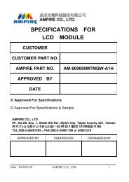
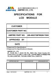
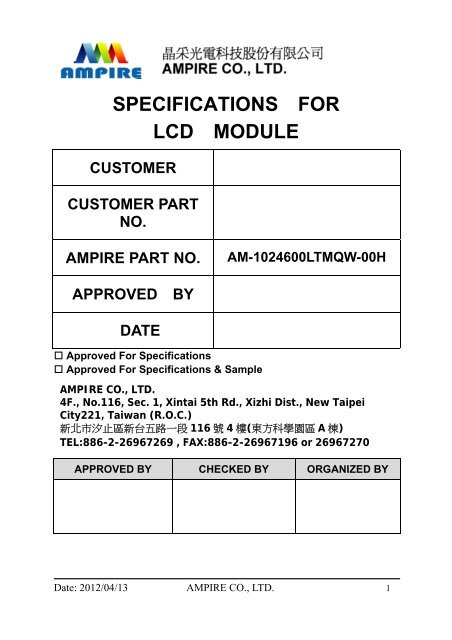
SPECIFICATIONS FOR<br />
<strong>LCD</strong> MODULE<br />
CUSTOMER<br />
CUSTOMER PART<br />
NO.<br />
AMPIRE PART NO. AM-1024600LTMQW-00H<br />
APPROVED BY<br />
DATE<br />
Approved For Specifications<br />
Approved For Specifications & S<strong>am</strong>ple<br />
AMPIRE CO., LTD.<br />
4F., No.116, Sec. 1, Xintai 5th Rd., Xizhi Dist., New Taipei<br />
City221, Taiwan (R.O.C.)<br />
新北市汐止區新台五路一段 116 號 4 樓(東方科學園區 A 棟)<br />
TEL:886-2-26967269 , FAX:886-2-26967196 or 26967270<br />
APPROVED BY CHECKED BY ORGANIZED BY<br />
Date: 2012/04/13 AMPIRE CO., LTD. 1
RECORD OF REVISION<br />
Revision Date Page Contents Editor<br />
2012/4/12<br />
2012/4/13<br />
-<br />
24<br />
New Release<br />
Correct the outline dimension<br />
Rober<br />
Rober<br />
Date: 2012/04/13 AMPIRE CO., LTD. 2
1. FEATURES<br />
The <strong>TFT</strong> is a color active matrix <strong>TFT</strong> <strong>LCD</strong> module using <strong>am</strong>orphous silicon <strong>TFT</strong>'s<br />
(Thin Film Transistors) as an active switching devices. This module is composed of a<br />
<strong>TFT</strong> <strong>LCD</strong> panel, a driving circuit and a back light system. This <strong>TFT</strong> <strong>LCD</strong> has a 10.1<br />
(17:10) inch diagonally measured active display area with WSVGA(1024 x 600 pixel)<br />
resolution.<br />
(1) 10.1 (17:10 diagonal) inch configuration<br />
(2) One channel LVDS interface<br />
(3) 262K color by 6 bit R.G.B signal input<br />
(4) RoHS Compliance<br />
(5) Halogen Free<br />
2. PHYSICAL SPECIFICATIONS<br />
Item Specifications Unit Note<br />
<strong>LCD</strong> size 10.1” (Diagonal) inch<br />
Active area 222.72 (H) ×125.28 (V) mm<br />
Number of pixels 1024(H) × 600(V) pixels<br />
Pixel pitch 0.2715(H) × 0.2088(V) mm<br />
Pixel arrangement RGB Vertical stripe<br />
Display colors 262,144 colors<br />
Display mode Normally white<br />
Dimensional outline 235.0 (Typ) ×145.8 (Typ) ×7.3(D) mm<br />
Back-light Single LED (Side-Light type)<br />
Weight TBD g<br />
Surface treatment Anti-glare<br />
Date: 2012/04/13 AMPIRE CO., LTD. 3
3. ABSOLUTE MAX. RATINGS<br />
The followings are maximum values which, if exceed, may cause faulty operation<br />
or d<strong>am</strong>age to the unit.<br />
Item Symbol<br />
Values<br />
Min. Max.<br />
UNIT Note<br />
LED Power Supply Voltage VLED -0.3 15.0 V GND=0<br />
Logic Supply Voltage VDD -0.3 5.0 V<br />
Operating Temperature TOPA -20 70<br />
Storage Temperature TSTG -30 80<br />
Date: 2012/04/13 AMPIRE CO., LTD. 4<br />
o C<br />
o C
4. ELECTRICAL CHARACTERISTICS<br />
4.1 <strong>TFT</strong> <strong>LCD</strong> Module<br />
Item Symbol<br />
Values<br />
Min. Typ. Max.<br />
UNIT Note<br />
Power voltage VDD 3.0 3.3 3.6 V Note1<br />
Current of power<br />
supply<br />
Power voltage for<br />
LED driver<br />
LED driver current<br />
of power supply<br />
Note 1: VDD-dip condition :<br />
when 2.7V≦VDD3.0V,VDD-dip condition should be s<strong>am</strong>e as VDD-turn-con condition.<br />
4.2 Switching Characteristics of LVDS Receiver<br />
VDD=3.3V<br />
Black pattern<br />
VLED=5V<br />
ADJ=100%<br />
Item Symbol Min. Typ. Max. Unit Condition<br />
Differential Input High<br />
Threshold<br />
Differential Input Low<br />
Threshold<br />
VTH -- -- 100 mV VCM=1.2V<br />
VTL -100 -- -- mV<br />
Input current IIN -10 -- +10 uA<br />
Differential input<br />
Voltage<br />
Common Mode<br />
Voltage Offset<br />
|VID| 0.2 -- 0.6 V<br />
VCM<br />
VID VID<br />
1.25 2.4- V<br />
2<br />
2<br />
LVDS VINP<br />
LVDS VINN<br />
Date: 2012/04/13 AMPIRE CO., LTD. 5
4.3 6-bit LVDS Input Data Mapping<br />
Date: 2012/04/13 AMPIRE CO., LTD. 6
4.4 Timing characteristics of input signals<br />
LVDS input<br />
signal sequence<br />
<strong>LCD</strong> input<br />
signal sequence<br />
(input LVDS<br />
Transmitter)<br />
DENA<br />
Item Symbol Min. Typ. Max. Unit<br />
Fr<strong>am</strong>e Rate tclk 41 51.2 57 MHz<br />
Horizontal<br />
Vertical<br />
Horizontal timing sequence<br />
Vertical timing sequence<br />
Horizontal total<br />
Timing<br />
Horizontal<br />
effective<br />
Timing<br />
Horizontal<br />
Blank Time<br />
Vertical total<br />
Time<br />
Vertical<br />
effective Time<br />
Vertical Blank<br />
Time<br />
tH 1214 1344 1364 tCLK<br />
tHA 1024 tCLK<br />
tHB 190 320 340 tCLK<br />
tV 615 365 645 tH<br />
tVA 600 tH<br />
tVB 15 35 45 tH<br />
Date: 2012/04/13 AMPIRE CO., LTD. 7
4.5 Backlight Driving Conditions<br />
Item Symbol<br />
LED Driver<br />
voltage<br />
Power Supply<br />
Current For<br />
LED Driver<br />
ADJ Input<br />
Voltage<br />
Values<br />
Min. Typ. Max.<br />
VLED 4.7 5 5.3 V<br />
ILED - 600 - mA<br />
VADJ - 3.3 VLED V<br />
LED voltage VAK -- 19.2 -- V<br />
LED current IL<br />
Unit Note<br />
VLED=5V<br />
VADJ=3.3V<br />
(duty 100%)<br />
duty=100%<br />
Note(3)<br />
IL =120mA<br />
Ta=25℃<br />
-- 120 -- mA Ta=25℃<br />
-- 100 -- mA Ta=60℃<br />
LED Life Time - -- 20K -- Hour Note (2)<br />
Note (1) The constant current source is needed for white LED back-light driving.<br />
When LCM is operated over 60 deg.C <strong>am</strong>bient temperature, the IL of the<br />
LED back-light should be adjusted to 100mA max<br />
There are 6 Groups LED shown as below , VLEDA-LEDK=10V ,Ta=25℃<br />
120mA<br />
LED_A<br />
LED_K<br />
Date: 2012/04/13 AMPIRE CO., LTD. 8<br />
20mA
Note2 : Condition: Ta=25℃, continuous lighting<br />
Life time is estimated data.<br />
Definitions of failure:<br />
1. LCM brightness becomes half of the minimum value.<br />
2. LED doesn’t light normally.<br />
When LCM is operated over 40℃ <strong>am</strong>bient temperature, the ILED should be<br />
follow :<br />
Date: 2012/04/13 AMPIRE CO., LTD. 9
5. OPTICAL SPECIFICATION<br />
5.1 Optical specification<br />
Item Symbol Condition<br />
Viewing angle<br />
Values<br />
Min. Typ. Max.<br />
θL<br />
60 70 --<br />
θR<br />
θU<br />
(CR≧10)<br />
60<br />
60<br />
70<br />
70<br />
--<br />
--<br />
θD 40 50 --<br />
Unit Note<br />
degree Note1<br />
Note2<br />
Response time<br />
TR<br />
TF<br />
--<br />
--<br />
5<br />
20<br />
7<br />
28<br />
msec<br />
msec<br />
Note3<br />
Contrast ratio CR 400 500 -- -- Note2<br />
WX 0.26 0.31 0.36 --<br />
WY 0.28 0.33 0.38 --<br />
Color chromaticity<br />
RX 0.54 0.59 0.64 --<br />
RY<br />
GX<br />
Normal<br />
θ=Φ=0°<br />
0.28<br />
0.29<br />
0.33<br />
0.34<br />
0.38<br />
0.39<br />
--<br />
--<br />
GY 0.54 0.59 0.64 --<br />
BX 0.11 0.16 0.21 --<br />
BY 0.05 0.1 0.15 --<br />
Date: 2012/04/13 AMPIRE CO., LTD. 10<br />
Note1<br />
Note4<br />
Luminance L 200 250 -- cd/m 2 Note4<br />
Luminance uniformity YU 70 -- -- % Note5<br />
5.2 Measuring Condition<br />
■ Measuring surrounding : dark room<br />
■ Ambient temperature : 25±2℃<br />
■ 15min. warm-up time
5.2 Measuring Equipment<br />
The optical characteristics should be measured in dark room. After 30 minutes<br />
operation, the optical properties are measured at the center point of the <strong>LCD</strong> screen.<br />
(Response time is measured by Photo detector TOPCON BM-7 of view : 1° / Height :<br />
120mm.)<br />
Note 1 : Definition of viewing angle range<br />
Note 2 : Definition of Contrast Ratio (CR) :<br />
measured at the center point of panel<br />
Date: 2012/04/13 AMPIRE CO., LTD. 11
Note 3 : Definition of Response time : Sum of TR and T<br />
Note 4 : Definition of optical measurement setup<br />
LED<br />
<strong>LCD</strong> Optical Detector<br />
Note 5 : Definition of brightness uniformity<br />
LED:ON, LIGHT:OFF<br />
Brightness gauge<br />
BM-7 (Topcon)<br />
(Min Luminance of 9 points)<br />
Luminance uniformity = ------------------------------------------------×100%<br />
(Max Luminance of 9 points)<br />
Date : 2012/04/13 AMPIRE CO., LTD. 12
Note 6 : Rubbing Direction (The different Rubbing Direction will cause the different<br />
optima view direction<br />
Note 7 : Condition: Ta=25℃, Life time is estimated data.<br />
Definitions of failure:<br />
i. LCM brightness becomes half of the minimum value.<br />
ii. LED doesn’t light normally.<br />
Date : 2012/4/13 AMPIRE CO., LTD. 13
6. BLOCK DIAGRAM<br />
6.1 <strong>TFT</strong><strong>LCD</strong> Module<br />
6.2 Pixel format<br />
Date : 2012/4/13 AMPIRE CO., LTD. 14
7.INTERFACE<br />
7.1 Electrical Interface Connection<br />
CN1(Input signal): CSTAR DS100-430-H23 (equivalent JAE FI-XB30SSRL-HF16)<br />
Pin No. Symbol Description Note<br />
1 GND Ground<br />
2 VDD 3.3V Power<br />
3 VDD 3.3V Power<br />
4 V_EDID 3.3V Power for EDID<br />
5 ADJ Adjust for LED brightness Note*<br />
6 CLK_EDID EDID Clock Input<br />
7 DATA_EDID EDID Data Input<br />
8 RXIN0- LVDS Signal - channel0-<br />
9 RXIN0+ LVDS Signal+ channel0+<br />
10 GND Ground<br />
11 RXIN1- Data Input channel1-<br />
12 RXIN1+ Data Input channel1+<br />
13 GND Ground<br />
14 RXIN2- Data Input channel2-<br />
15 RXIN2+ Data Input channel2+<br />
16 GND Ground<br />
17 RXCLKIN- Data Input CLK-<br />
18 RXCLKIN+ Data Input CLK+<br />
19 GND Ground<br />
20 NC No connection<br />
21 NC No connection<br />
22 GND Ground<br />
23 GND Ground<br />
24 VLED VLED Power +5V<br />
Date : 2012/4/13 AMPIRE CO., LTD. 15
25 VLED VLED Power +5V<br />
26 VLED VLED Power +5V<br />
27 NC No connection<br />
28 NC No connection<br />
29 NC No connection<br />
30 NC No connection<br />
Note* : The brightness of <strong>LCD</strong> panel could be changed by adjusting ADJ<br />
Date : 2012/4/13 AMPIRE CO., LTD. 16
(3) LVDS Connector : CSTAR DS100-430-H23<br />
Date : 2012/4/13 AMPIRE CO., LTD. 17
8. Power On/Off Sequence<br />
Note:<br />
Item Min. Typ. Max. Unit Remark<br />
TP1 0.5 -- 10 msec<br />
TP2 0 -- 50 msec<br />
TP3 0 -- 50 msec<br />
TP4 500 -- -- msec<br />
TP5 200 -- -- msec<br />
TP6 200 -- -- msec<br />
(1) The supply voltage of the external system for the module input should be the s<strong>am</strong>e as the<br />
definition of VDD.<br />
(2) Apply the l<strong>am</strong>p voltage within the <strong>LCD</strong> operation range. When the back-light turns on before the<br />
<strong>LCD</strong> operation or the <strong>LCD</strong> turns off before the back-light turns off, the display may momentarily<br />
become white.<br />
(3) In case of VDD = off level, please keep the level of input signal on the low or keep a high<br />
impedance.<br />
(4) TP4 should be measured after the module has been fully discharged between power off and on<br />
period.<br />
(5) Interface signal shall not be kept at high impedance when the power is on.<br />
Date : 2012/4/13 AMPIRE CO., LTD. 18
9. RELIABILITY TEST CONDITIONS<br />
Item Test Conditions Note<br />
High Temperature Storage Ta = 80℃ 240 hrs<br />
Low Temperature Storage Ta = -30℃ 240 hrs<br />
High Temperature Operation Ts = 70℃ 240 hrs<br />
Low Temperature Operation Ta = -20℃ 240 hrs<br />
Thermal Shock -30℃ /30 min ~ +80℃ /30 min 100 cycles<br />
Storage / Operating temperature<br />
Note .Max wet bulb temp.=39oC<br />
Date : 2012/4/13 AMPIRE CO., LTD. 19
10.INCOMING INSEPCTION STANDARDS<br />
10.1. Scope<br />
Specifications contain<br />
10.1.1 Display Quality Evaluation<br />
10.1.2 Mechanics Specification<br />
10.2. S<strong>am</strong>pling Plan<br />
Unless there is other agreement, the s<strong>am</strong>pling plan for incoming inspection shall<br />
follow MIL-STD-105E LEVEL II.<br />
10.2.1 Lot size: Quantity per shipment as one lot (different model as different lot ).<br />
10.2.2 S<strong>am</strong>pling type: Normal inspection, single s<strong>am</strong>pling.<br />
10.2.3 S<strong>am</strong>pling level: Level II.<br />
10.2.4 AQL: Acceptable Quality Level<br />
Major defect: AQL=0.65<br />
Minor defect: AQL=1.0<br />
10.3. Panel Inspection Condition<br />
10.3.1 Environment:<br />
Room Temperature: 25±5°C.<br />
Humidity: 65±5% RH.<br />
Illumination: 300 ~ 700 Lux.<br />
10.3.2 Inspection Distance:<br />
35-40 cm<br />
10.3.3 Inspection Angle:<br />
The vision of inspector should be perpendicular to the surface of the Module.<br />
10.3.4 Inspection time:<br />
Perceptibility Test Time: 20 seconds max.<br />
10.4. Display Quality<br />
10.4.1 Function Related:<br />
The function defects of line defect, abnormal display, and no display are<br />
considered Major defects.<br />
Date : 2012/4/13 AMPIRE CO., LTD. 20
10.4.2 Bright/Dark Dots:<br />
Defect Type / Specification G0 Grade A Grade<br />
Bright Dots 0 N3<br />
Dark Dots 0 N4<br />
Total Bright and Dark Dots 0 N6<br />
[Note 1]<br />
Judge defect dot and adjacent dot as following.<br />
(1) One pixel consists of 3 sub-pixels, including R,G, and B dot.(Sub-pixel = Dot)<br />
(2) The definition of dot: The size of a defective dot over 1/2 of whole dot is regarded<br />
as one defective dot.<br />
(3) Allow above (as A, B, C and D status) adjacent defect dots, including bright and<br />
dart adjacent dot. And they will be counted 2 defect dots in total quantity.<br />
(4) Defects on the Black Matrix, out of Display area, are not considered as a defect or<br />
counted.<br />
(5) There should be no distinct non-uniformity visible through 3% ND Filter within 2<br />
sec inspection times.<br />
10.4.3 Visual Inspection specifications:<br />
Dot Shape<br />
Defect Type Specification Count(N)<br />
(Particle、Scratch and Bubbles in<br />
display area)<br />
D0.25mm Ignored<br />
0.25mm0.5mm N=0<br />
Line Shape W0.07mm Ignored<br />
Date : 2012/4/13 AMPIRE CO., LTD. 21
(Particles、Scratch、Lint and<br />
Bubbles in display area)<br />
0.07mm0.1mm, L>5mm N=0<br />
[Note 2] W : Width[mm], L : Length[mm], N : Number, φ : Average Di<strong>am</strong>eter<br />
[Note 3] Bright dot is defined through 3% transmission ND Filter as following.<br />
Date : 2012/4/13 AMPIRE CO., LTD. 22
11. HANDLING & CAUTIONS<br />
11.1 Cautions when taking out the module<br />
Pick the pouch only, when taking out module from a shipping package.<br />
11.2 Cautions for handling the module<br />
11.2.1 As the electrostatic discharges may break the <strong>LCD</strong> module, handle the<br />
<strong>LCD</strong> module with care. Peel a protection sheet off from the <strong>LCD</strong> panel<br />
surface as slowly as possible.<br />
11.2.2 As the <strong>LCD</strong> panel and backlight element are made from fragile glass<br />
material, impulse and pressure to the <strong>LCD</strong> module should be avoided.<br />
11.2.3 As the surface of the polarizer is very soft and easily scratched, use a<br />
soft dry cloth without chemicals for cleaning.<br />
11.2.4 Do not pull the interface connector in or out while the <strong>LCD</strong> module is<br />
operating.<br />
11.2.5 Put the module display side down on a flat horizontal plane.<br />
11.2.6 Handle connectors and cables with care.<br />
11.3 Cautions for the operation<br />
11.3.1 When the module is operating, do not lose MCLK, DE signals. If any one<br />
of these signals were lost, the <strong>LCD</strong> panel would be d<strong>am</strong>aged.<br />
11.3.2 Obey the supply voltage sequence. If wrong sequence were applied, the<br />
module would be d<strong>am</strong>aged.<br />
11 .4 Cautions for the atmosphere<br />
11.4.1 Dewdrop atmosphere should be avoided.<br />
11.4.2 Do not store and/or operate the <strong>LCD</strong> module in a high temperature and/or<br />
humidity atmosphere. Storage in an electro-conductive polymer-packing<br />
pouch and under relatively low temperature atmosphere is recommended.<br />
11.5 Cautions for the module characteristics<br />
11.5.1 Do not apply fixed pattern data signal to the <strong>LCD</strong> module at product<br />
aging.<br />
11.5.2 Applying fixed pattern for a long time may cause image sticking.<br />
11.6 Other cautions<br />
11.6.1 Do not disassemble and/or re-assemble <strong>LCD</strong> module.<br />
11.6.2 Do not re-adjust variable resistor or switch etc.<br />
11.6.3 When returning the module for repair or etc, please pack the module not<br />
to be broken. We recommend using the original shipping packages.<br />
11.6.4 AMIPRE will provide one year warrantee for all products and three months<br />
warrantee for all repairing products.<br />
Date : 2012/4/13 AMPIRE CO., LTD. 23
12. OUTLINE DIMENSION<br />
Date : 2012/4/13 AMPIRE CO., LTD. 24
Date : 2012/4/13 AMPIRE CO., LTD. 25