a modified uwb wilkinson power divider using delta stub b. - PIER
a modified uwb wilkinson power divider using delta stub b. - PIER
a modified uwb wilkinson power divider using delta stub b. - PIER

You also want an ePaper? Increase the reach of your titles
YUMPU automatically turns print PDFs into web optimized ePapers that Google loves.
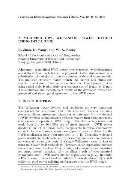
Progress In Electromagnetics Research Letters, Vol. 19, 49–55, 2010<br />
A MODIFIED UWB WILKINSON POWER DIVIDER<br />
USING DELTA STUB<br />
B. Zhou, H. Wang, and W.-X. Sheng<br />
School of Electronics and Optical Engineering<br />
Nanjing University of Science and Technology<br />
Nanjing, Jiangsu 210094, China<br />
Abstract—A <strong>modified</strong> UWB <strong>power</strong> <strong>divider</strong> formed by implementing<br />
one <strong>delta</strong> <strong>stub</strong> on each branch is proposed. Delta <strong>stub</strong> is used as a<br />
substitution of radial <strong>stub</strong> that can present wideband characteristic.<br />
The proposed structure makes branch line shorter and <strong>stub</strong>’s size<br />
smaller than those of similar works based on UWB <strong>power</strong> <strong>divider</strong><br />
<strong>using</strong> radial <strong>stub</strong>. It also achieves a compact size of 18 mm by 13 mm.<br />
The simulation and measurement results of the developed <strong>divider</strong> are<br />
presented and shown good agreement in the UWB range.<br />
1. INTRODUCTION<br />
The Wilkinson <strong>power</strong> <strong>divider</strong>s and combiners are very important<br />
components for microwave and millimeter-wave circuits including<br />
<strong>power</strong> amplifiers, mixers and phased-array antennas. Ultra-wideband<br />
(UWB) wireless communication systems require their radio frequency<br />
components to operate in UWB range. Therefore, components that<br />
work from 3.1 to 10.6 GHz are of great interest. UWB <strong>power</strong><br />
<strong>divider</strong> is one of the most useful components in various microwave<br />
circuits. In recent years, many new types of <strong>power</strong> <strong>divider</strong>s for the<br />
UWB application have been proposed in [1–4]. Normally, wideband<br />
<strong>power</strong> <strong>divider</strong> [5] can be achieved by cascading multi-section matching<br />
networks at two output ports of a single Wilkinson <strong>power</strong> <strong>divider</strong> or<br />
<strong>using</strong> multilayer PCB technology. However, those approaches increase<br />
the size and insertion loss of the circuit, and it requires more resistors<br />
for output ports’ isolation. By installing a pair of open-circuited<br />
rectangular <strong>stub</strong>, UWB <strong>power</strong> <strong>divider</strong> is proposed in [6, 7]. Recently,<br />
a UWB <strong>power</strong> <strong>divider</strong> based on radial <strong>stub</strong> was developed [8], and it<br />
exhibited good <strong>power</strong> splitting performance over the UWB range.<br />
Received 18 October 2010, Accepted 15 November 2010, Scheduled 22 November 2010<br />
Corresponding author: Bo Zhou (sarahxboy@hotmail.com).
50 Zhou, Wang, and Sheng<br />
Figure 1. The schematic diagram of the proposed UWB <strong>power</strong><br />
<strong>divider</strong>.<br />
Delta <strong>stub</strong> was first proposed by De Lima Coimbra [9]. Its shape is<br />
an isosceles triangle as Greek letter “Delta”. Although <strong>delta</strong> <strong>stub</strong> has<br />
been proposed for a long time, it is seldom used as impedance match<br />
element in microwave components design. Like radial <strong>stub</strong>, <strong>delta</strong> <strong>stub</strong><br />
can present wider bandwidth. Compared with radial <strong>stub</strong>, <strong>delta</strong> <strong>stub</strong><br />
is a good alternative to be the radial <strong>stub</strong>, and it is useful in wherever a<br />
radial <strong>stub</strong> would be chosen and has simpler contour due to its straight<br />
sides, so it is easier to lay out on PCB.<br />
In the paper, we design an UWB <strong>power</strong> <strong>divider</strong> with <strong>delta</strong> <strong>stub</strong>s.<br />
As far as we know, it is the very first time that <strong>delta</strong> <strong>stub</strong> is used<br />
as impedance match element in <strong>power</strong> <strong>divider</strong>’s design. With the<br />
proposed <strong>delta</strong> <strong>stub</strong>, the overall <strong>divider</strong> length and <strong>stub</strong> size can be<br />
reduced compared with the one in [8], and it is easier for designer to<br />
lay out than a radial <strong>stub</strong>. The simulated and measured results of the<br />
proposed <strong>divider</strong> show good return loss, insertion loss and isolation<br />
performance across the band from 3.1 to 10.6 GHz.<br />
Figure 1 shows the schematic diagram of the proposed UWB <strong>power</strong><br />
<strong>divider</strong> <strong>modified</strong> from the one proposed by Ahmed and Sebak in [8].<br />
Here, single open radial <strong>stub</strong> of each branch is substituted by a <strong>delta</strong><br />
<strong>stub</strong>. The reason for <strong>using</strong> <strong>delta</strong> <strong>stub</strong> instead of radial ones is to<br />
obtain shorter branch line, smaller <strong>stub</strong> and easier layout. By adjusting<br />
dimension parameter of <strong>delta</strong> <strong>stub</strong>, the bandwidth can be broadened.<br />
The impedances of input and output ports of the proposed <strong>power</strong><br />
<strong>divider</strong> are both 50 Ω, and the characteristic impedance of the first and<br />
second branch transmission lines are Z1 = Z2 = 83 Ω. The electrical<br />
lengths of the first and second transmission lines are θ1 = 35.64 ◦ and<br />
θ2 = 29.83 ◦ at the center frequency of 6.85 GHz, respectively. So the<br />
length of branch line (L1 + L2 + Wg) is much shorter than traditional<br />
Wilkinson <strong>power</strong> <strong>divider</strong> with 90 ◦ branch line. Since this <strong>divider</strong> is<br />
symmetric, the even and odd mode analysis can be used to determine<br />
the parameters for the proposed UWB <strong>divider</strong>.
Progress In Electromagnetics Research Letters, Vol. 19, 2010 51<br />
Figure 2. Geometry of the <strong>delta</strong><br />
<strong>stub</strong>.<br />
Figure 3. Equivalent circuit of<br />
<strong>delta</strong> <strong>stub</strong>.<br />
Coimbra and Mauro [10] recommend modeling the <strong>delta</strong> <strong>stub</strong> by a<br />
series of n transmission line segments of length δ. The open end of the<br />
<strong>delta</strong> <strong>stub</strong> is transferred by the equivalent line length to a short circuit<br />
at the reference plane T , shown in Fig. 2 and Fig. 3. Tapered line can<br />
be treated as a series of transmission line with different characteristic<br />
impedances. The number, n, is chosen so that each segment is δ ≪ λg<br />
in length. Each segment’s characteristic impedance is calculated with<br />
the standard microstrip line equations with the exception of the final<br />
section, which includes the open end discontinuity. Widths of each<br />
transmission line are computed by<br />
W = 2nδtg(∂/2) n = 0, 1, . . . , x (1)<br />
where ∂ is vertex angle of the <strong>delta</strong> <strong>stub</strong> in Fig. 2. Thus when<br />
W/d 1, it is convenient to calculate the characteristic impedance<br />
of each segment by<br />
Z0 =<br />
120π<br />
√<br />
εe[W/d + 1.393 + 0.667 ln(W/d + 1.444)]<br />
(2)<br />
εe = εr + 1<br />
2 + εr − 1 1<br />
<br />
2 1 + 12d/W<br />
where εr is the dielectric constant of PCB substrate, and εe is the<br />
effective dielectric constant of a microstrip line. d is the thickness of<br />
PCB substrate.<br />
The relation between the width of the feeding line W g and inner<br />
radius ri of the <strong>delta</strong> <strong>stub</strong> is given by<br />
W g = 2ri sin ∂<br />
(4)<br />
For a load impedance ZL, input impedance of a lossless transmission<br />
line with length L and characteristic impedance of Z0 can be computed<br />
2<br />
(3)
52 Zhou, Wang, and Sheng<br />
by<br />
ZL + jZ0tgβl<br />
Zin(l) = Z0<br />
Z0 + jZLtgβl<br />
where β is the phase constant of the transmission, and ZL is impedance<br />
of the last transmission line segment Zn, so ZL is<br />
120π<br />
ZL = √ (6)<br />
εe[W (nδ)/d + 1.393 + 0.667 ln(W (nδ)/d + 1.444)]<br />
Since <strong>delta</strong> <strong>stub</strong> is considered as the cascaded interconnections<br />
of transmission line with equal incremental distance of δ, the input<br />
impedance at m + δ(∆Z = Zin + dZin) is<br />
Zin + jZ0tg(βδ)<br />
∆Z = Z0<br />
Z0 + jZintg(βδ)<br />
The input impedance of the <strong>delta</strong> <strong>stub</strong> can be found from the<br />
computation of the input impedance of each cascaded transmission<br />
line with incremental distance δ successfully.<br />
According to (1)–(7) and with the help of CAD program<br />
optimization, we set the segments quantity n as 100 for calculating<br />
impedance of the <strong>delta</strong> <strong>stub</strong>, then electrical parameters for the <strong>delta</strong><br />
<strong>stub</strong> are derived as Wg = 1.1 mm, L = 1.71 mm, ri = 1.14 mm and<br />
α = 58 ◦ . Those parameters of <strong>delta</strong> <strong>stub</strong> are well matched with branch<br />
lines’ impedance Z1 and Z2 in order to obtain wide bandwidth. And<br />
a 100 Ω resistor is used to enhance output ports’ isolation.<br />
2. SIMULATION AND MEASUREMENT RESULTS<br />
AWR EMSight simulator [11] which is a full-wave electromagnetic<br />
solver in Microwave Office 2008 is used for the simulation of UWB<br />
Figure 4. Layout of the proposed<br />
UWB <strong>power</strong> <strong>divider</strong>.<br />
(5)<br />
(7)<br />
Figure 5. Photograph of the<br />
proposed UWB <strong>power</strong> <strong>divider</strong>.
Progress In Electromagnetics Research Letters, Vol. 19, 2010 53<br />
<strong>power</strong> <strong>divider</strong>. To acquire a wideband in which the input return loss,<br />
output return loss and isolation between two output ports are less<br />
than the criteria of 10 dB. Many dimensions of the <strong>power</strong> <strong>divider</strong> have<br />
been simulated. By optimization with software Microwave Office 2008,<br />
we set dimension parameters of the proposed UWB <strong>power</strong> <strong>divider</strong><br />
as: W0 = 1.14 mm, L0 = 8 mm, L1 = 2.76 mm, L2 = 2.31 mm,<br />
L = 1.71 mm, α = 58 ◦ and R = 100 Ω, shown in Fig. 4. Length of<br />
branch line and <strong>stub</strong> become shorter than the one in [8].<br />
The proposed UWB <strong>power</strong> <strong>divider</strong> is fabricated on the RO4003C<br />
substrate with a dielectric constant of 3.38 and a thickness of 0.508 mm.<br />
Fig. 5 shows a photograph of the proposed <strong>divider</strong>, and the overall<br />
dimension of the fabricated UWB <strong>power</strong> <strong>divider</strong> circuit is only 18 mm×<br />
13 mm. All measured data are collected from the HP N5230A network<br />
analyzer. The simulated and measured S-parameters are presented in<br />
Fig. 6, respectively.<br />
As shown in Fig. 6(a) and Fig. 6(b), the measured result of the<br />
insertion loss is better than 0.3 dB which indicates the proposed UWB<br />
(a)<br />
(b)
54 Zhou, Wang, and Sheng<br />
(c)<br />
Figure 6. Simulated and measured parameters of proposed UWB<br />
<strong>power</strong> <strong>divider</strong>, (a) S11 and S21 parameters, (b) S22 and S23 parameters<br />
and (c) group delay parameter.<br />
<strong>power</strong> <strong>divider</strong> can split an incoming signal into two parts successfully.<br />
The measured input return loss and output ports’ isolation are better<br />
than −10 dB, and output return loss is better than −15 dB across the<br />
UWB range. Fig. 6(c) presents the simulated and measured group<br />
delay between the input and output ports. The group delay of the<br />
proposed UWB <strong>power</strong> <strong>divider</strong> is almost constant and less than 0.13 ns<br />
which shows good linearity within the UWB frequency range. The<br />
discrepancy between measured and simulated results of the group delay<br />
is caused by tolerance of PCB fabrication and soldering tolerance of<br />
100 Ω and SMA connectors.<br />
3. CONCLUSION<br />
A <strong>modified</strong> UWB <strong>power</strong> <strong>divider</strong> with <strong>delta</strong> <strong>stub</strong> on each branch is<br />
proposed and implemented. Shorter branch line, smaller <strong>stub</strong> and<br />
compact size have been achieved by <strong>using</strong> <strong>delta</strong> <strong>stub</strong>. Compared with<br />
radial <strong>stub</strong>, <strong>delta</strong> <strong>stub</strong> is easier to layout due to its straight sides. Good<br />
impedance matching, <strong>power</strong> splitting and isolation performance are<br />
achieved over the UWB range shown by simulation and measurement<br />
results.<br />
ACKNOWLEDGMENT<br />
The authors would like to acknowledge the collaborative work with<br />
Nanjing Ericsson Company for PCB manufacturing.
Progress In Electromagnetics Research Letters, Vol. 19, 2010 55<br />
REFERENCES<br />
1. Abbosh, A., “Multilayer inphase <strong>power</strong> <strong>divider</strong> for UWB<br />
applications,” Microwave Opt. Technol. Lett., Vol. 50, No. 5, 1402–<br />
1405, May 2008.<br />
2. Lin, Z. and Q. X. Chu, “A compact spatial UWB <strong>power</strong> <strong>divider</strong><br />
with 1 to 4 ways,” 2008 Asia-Pacific Microwave Conference, 1–4,<br />
2008.<br />
3. Bialkowski, M. and A. Abbosh, “Design of a compact UWB outof-phase<br />
<strong>power</strong> <strong>divider</strong>,” IEEE Microw. Wireless Compon. Lett.,<br />
Vol. 17, No. 4, 289–291, Apr. 2007.<br />
4. Abbosh A., “A compact UWB three-way <strong>power</strong> <strong>divider</strong>,” IEEE<br />
Microw. Wireless Compon. Lett., Vol. 17, No. 8, 598–600,<br />
Aug. 2007.<br />
5. Chieh, J. C. S and A. V. Pham, “Development of a<br />
wide bandwidth <strong>wilkinson</strong> <strong>power</strong> <strong>divider</strong> on multilayer organic<br />
substrates,” Microwave Opt. Technol. Lett., Vol. 52, No. 7, 1606–<br />
1609, Jul. 2010.<br />
6. Wong, S. W. and L. Zhu, “Ultra-wideband <strong>power</strong> <strong>divider</strong><br />
with good in-band splitting and isolation performances,” IEEE<br />
Microwave Wireless Compon. Lett., Vol. 18, No. 8, Aug. 2008.<br />
7. Ou, X. P. and Q. X. Chu, “A Modified two-section UWB<br />
Wilkinson <strong>power</strong> <strong>divider</strong>,” ICMMT Proceedings, 2008.<br />
8. Ahmed, O. and A. R. Sebak, “A <strong>modified</strong> <strong>wilkinson</strong> <strong>power</strong><br />
<strong>divider</strong>/combiner for ultrawideband communications,” IEEE<br />
Antennas and Propagation Society International Symposium, 1–<br />
4, 2009.<br />
9. De Lima Coimbra, M., “A new kind of radial <strong>stub</strong> and some<br />
applications,” Proc. XIV Eur. Microwave Conf., 516–521, Liege,<br />
Belgium, 1984.<br />
10. Coimbra and L. Mauro, “The generalized <strong>delta</strong> <strong>stub</strong>s,” 1987<br />
International Microwave Symposium Proceedings, 1071–1075,<br />
1987.<br />
11. Microwave Office software, AWR Design Environment Company,<br />
2008.