CPW-FED SLEEVE MONOPOLE ANTENNA WITH - PIER
CPW-FED SLEEVE MONOPOLE ANTENNA WITH - PIER
CPW-FED SLEEVE MONOPOLE ANTENNA WITH - PIER

You also want an ePaper? Increase the reach of your titles
YUMPU automatically turns print PDFs into web optimized ePapers that Google loves.
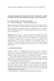
Progress In Electromagnetics Research C, Vol. 14, 23–31, 2010<br />
<strong>CPW</strong>-<strong>FED</strong> <strong>SLEEVE</strong> <strong>MONOPOLE</strong> <strong>ANTENNA</strong> <strong>WITH</strong><br />
COMPLEMENTARY SIR RADIATORS FOR DTV SIG-<br />
NAL RECEPTION AND CIRCULARLY POLARIZED AP-<br />
PLICATIONS<br />
J. C. Liu, S. H. Chiu, K. D. Yeh, and B. H. Zeng<br />
Department of Electrical Engineering<br />
Ching Yun University<br />
Chung-Li, Tao-Yuan 32097, Taiwan, R.O.C.<br />
H. C. Wu<br />
Joymax Electronics Co., Ltd.<br />
Chung-li, Tao-Yuan 32063, Taiwan, R.O.C.<br />
T. F. Hung<br />
Department of Electrical Engineering<br />
Feng Chia University<br />
Taichung, Taiwan, R.O.C.<br />
Abstract—A new circularly-polarized (CP) sleeve antenna fed by<br />
a <strong>CPW</strong> for DTV signal reception applications is presented in this<br />
paper. The <strong>CPW</strong>-fed sleeve monopole antenna consists of square loop<br />
sleeve, <strong>CPW</strong>-fed and complementary SIR radiators. The lower and<br />
upper resonance frequencies of the desired band are controlled by the<br />
complementary SIR arms, making designs of the wide-band antenna<br />
very easy. To demonstrate the idea, the proposed antenna was designed<br />
at the band with 470–863 GHz (BW = 393 MHz, 58.9%) for DTV<br />
UHF-bands. The antenna gains are varied about 2.2 to 4.0 dBi. An<br />
omnidirectional radiation property is also shown. The CP operation<br />
for the proposed design can be achieved by properly adjusting the<br />
asymmetrical radiators. The reflection coefficient, axial ratio, radiation<br />
pattern and gain of the proposed antenna were studied, and reasonable<br />
agreement between the simulated and measured results was obtained.<br />
Corresponding author: J. C. Liu (jichyun@cyu.edu.tw).
24 Liu et al.<br />
1. INTRODUCTION<br />
The digital television (DTV) reception has been very attractive<br />
for applications in recent wireless communications. Many kinds of<br />
antennas for DTV reception have been studied [1–16], and delivering<br />
broadcast television signals to various terminals such as mobile<br />
phone [1], laptop computer [2, 3], multi-media player [4–6], vehicle [7]<br />
and the reception devices [8–16], etc.<br />
Basically, these structures belong to the monopole [2, 4–7, 11–15],<br />
dipole [1, 3, 8–10], planar [17] and the loop [16]. The characteristics of<br />
these antennas include broadband, compact, omidirectional patterns<br />
and high gain. In which, the sleeve monopole antenna is an attractive<br />
candidate for its impedance performance [11, 12, 15]. However, the<br />
circular polarization of these antennas has not been studied for DTV<br />
applications. Recent research has shown that there are certain benefits<br />
of polarization diversity and good reception to use circularly polarized<br />
(CP) antennas.<br />
Based on the sleeve monopole antenna [11, 12, 15], two complementary<br />
SIR radiators with longer and shorter electrical length are<br />
resonated for the lower and higher resonances of the desired band<br />
respectively. By inserting a parasitic sleeve with square loop, the<br />
impedance performance is dramatically improved. The asymmetrical<br />
radiators consists of the step impedance resonator (SIR) [14] and the<br />
complementary configuration [18, 19]. The CP operation for the proposed<br />
design can be achieved by properly adjusting the asymmetrical<br />
radiators. The variations of gap width and coupled space are studied<br />
for optimization. Orthogonal mode in surface current density and AR<br />
spectrums are applied for demonstrating the circular polarizations for<br />
UHF-bands. Also, the proposed antenna can be regarded as the antenna<br />
having <strong>CPW</strong>-fed. It is an available antenna for DTV reception<br />
and CP applications in spite of the compact size.<br />
2. <strong>ANTENNA</strong> CONFIGURATION AND BASIS<br />
The configuration of the proposed antenna is shown in Fig. 1. FR4<br />
substrate with thickness 1.6 mm is used. The dimensions are W1 =<br />
145.5 mm, W2 = 75 mm, W3 = 8 mm, W4 = W7 = 10 mm, W5 = 2 mm,<br />
W6 = 8 mm, W8 = 59.5 mm, Wf = 5.5 mm, s1 = 0.5 mm, s2 = 3 mm,<br />
L1 = 160 mm, L2 = 10 mm, L3 = 16 mm, L4 = 12 mm, L5 = 5.5 mm<br />
and L6 = 50 mm. The antenna is excited by using a <strong>CPW</strong>-fed<br />
and parasitized with a square loop sleeve. The antenna has two<br />
resonant distributions due to complementary SIR radiators shown in<br />
Fig. 2. The first (lower) and second (higher) resonant frequencies are
Progress In Electromagnetics Research C, Vol. 14, 2010 25<br />
Figure 1. Configuration of<br />
the proposed <strong>CPW</strong>-fed sleeve<br />
monopole antenna.<br />
Figure 2. Characteristics of two<br />
resonance and orthogonal modes.<br />
determined by dimensions of the path 1 and 2, respectively. In the<br />
path 1 for the resonance at lower frequency (510 MHz), L-shaped are<br />
added to lengthen the path of the average current for the resonance<br />
at higher frequency (770 MHz) in the path 2. Path 2 represents the<br />
second resonant distribution among the complementary SIR radiators<br />
with shorter electrical length. Therefore, if we adjust the resonant<br />
frequencies caused by the path 1 and 2, the proposed antenna can<br />
effectively cover broad DTV band (470–863 MHz). Orthogonal modes<br />
with first mode (#1) and second mode (#2) are also shown in Fig. 2.<br />
3. SIMULATION AND MEASUREMENT<br />
The S11 spectrums of the proposed antenna with UHF-bands are shown<br />
in Fig. 3. The simulated and measured results of frequency responses<br />
are in agreement. In measurement, while the return loss is smaller than<br />
−10 dB, the frequency responses cover the bands from 470 to 863 GHz<br />
(BW = 393 MHz, 58.9%) for the DTV reception terminals.<br />
Figures 4(a) and (b) illustrate the simulated current distributions<br />
among the planar structures respectively, which provide a clearly<br />
physical insight on understanding the characteristics of the proposed<br />
antenna [20]. Fig. 4(a) shows the complementary SIR radiators<br />
are excited with L-shaped concentrating current distributions at the<br />
510 MHz resonances while only one maximum (red) located at the<br />
center of left SIR arm and two maximum (red) split to both side<br />
of right SIR arm. In addition, the first mode (#1) and the second
26 Liu et al.<br />
mode (#2) directions are shown as the arrow. Similarly, Fig. 4(b)<br />
shows the complementary SIR radiators are excited with I-shaped<br />
concentrating current distributions at the 770 MHz resonances while<br />
only one maximum located at the center of left SIR arm and two<br />
maximum split to both side of right SIR arm. And the first mode<br />
(#1) and the second mode (#2) directions are shown as the arrow.<br />
Obviously, the necessary two orthogonal modes in the antenna can be<br />
presented. This is confirmed from obtaining the CP characteristics of<br />
the proposed antenna.<br />
Since the two quasi-degenerate orthogonal modes of unequal<br />
amplitude and phase difference are excited, the purity of circular<br />
polarization will be relatively less. Thus, the circular polarization,<br />
related to direction, the variations of the observed angle are<br />
investigated and presented in Figs. 5(a) and (b). The minimum AR<br />
Figure 3. S11 spectrums of the<br />
proposed antenna.<br />
(a) (b)<br />
Figure 4. Simulated current<br />
distributions (a) 510 MHz<br />
(b) 770 MHz.<br />
(a) (b)<br />
Figure 5. Axial ratio spectrum. (a) 510 MHz. (b) 770 MHz.
Progress In Electromagnetics Research C, Vol. 14, 2010 27<br />
with 0.38 dB at θ = 100 ◦ , ϕ = 0 ◦ and the circular polarizations<br />
(3 dB BW = 130 MHz) are observed for 510 MHz band. Meantime,<br />
the minimum AR with 1.21 dB at θ = 78 ◦ , ϕ = 0 ◦ and the<br />
circular polarizations (3 dB BW = 215 MHz) are observed for 770 MHz.<br />
Thus the proposed antenna can be applied to circular polarization<br />
applications which represents one of the availability and usefulness in<br />
contrast to the conventional antennas.<br />
The MI-3600 antenna measurement system in Joymax Electronics<br />
Laboratory is used for measurement. The proposed antenna is located<br />
on the X-Y plane and the feeding line is along the Y -axis. Two<br />
cut patterns with resonant 510 MHz and 770 MHz are represented in<br />
Figs. 6(a) and (b) respectively. Broadside patterns are observed in the<br />
X-Z cut planes, and quasi-omnidirectional patterns are obtained in<br />
the Y -Z cut planes. The AR spectrum results with asterisk are also<br />
measured and presented in Figs. 5(a) and (b). These are in agreed<br />
with the simulations. The 3-D radiation patterns observed in both X-<br />
Z and Y -Z planes are presented in Figs. 7(a) and (b) [21]. The quasi-<br />
Figure 6. Antenna radiation patterns. (a) Simulation. (b) Measurement.<br />
(a)<br />
(b)
28 Liu et al.<br />
omnidirectional patterns are shown in both 510 MHz and 770 MHz<br />
resonances and the 770 MHz radiation patterns present higher gain<br />
the 510 MHz radiation patterns. The measured antenna gain is varied<br />
about 2.2 to 4.0 dBi shown in Fig. 8.<br />
For the design methodology, the center frequency of the response<br />
is decided by the square loop sleeve length. The bandwidth determined<br />
by the lower and upper resonances is related to the path 1 SIR and the<br />
path 2 SIR dimensions respectively. The flat response can be controlled<br />
by the gap width.<br />
Figure 7. 3-D radiation patterns. (a) 510 MHz. (b) 770 MHz.<br />
Figure 8. Antenna gain.<br />
(a)<br />
(b)
Progress In Electromagnetics Research C, Vol. 14, 2010 29<br />
4. CONCLUSION<br />
A novel broadband <strong>CPW</strong>-fed sleeve monopole antenna has been<br />
constructed and experimentally studied. The measured results of the<br />
proposed antenna show that this design not only provides a wide<br />
operating bandwidth (BW = 393 MHz, 58.9%) with good impedance<br />
matching covering the whole DTV band (from 470 to 863 GHz) but also<br />
deliver high antenna gain varied about 2.2 to 4.0 dBi. An attractive<br />
feature of the antenna is its circularly-polarized characteristic due to<br />
the orthogonal mode among the complementary SIR radiators. The<br />
proposed antenna is a valuable candidate for DVB signal reception and<br />
CP applications.<br />
REFERENCES<br />
1. Wong, K. L., Y. W. Chi, B. Chen, and S. Yang, “Internal DTV<br />
antenna for folder-type mobile phone,” Microwave and Optical<br />
Technology Lett., Vol. 48, No. 6, 1015–1019, Jun. 2006.<br />
2. Pazin, L. and Y. Leviatan, “Flat-plate pentagonal monopole<br />
antenna for laptop wireless communication and mobile TV<br />
reception,” Microwave and Optical Technology Lett., Vol. 51,<br />
No. 3, 612–615, Mar. 2009.<br />
3. Li, W. Y., K. L. Wong, and S. W. Su, “Broadband integrated DTV<br />
antenna for USB dongle application,” Microwave and Optical<br />
Technology Lett., Vol. 49, 1018–1021, May 2007.<br />
4. Li, W. Y., K. L. Wong, and J. S. Row, “Broadband planar shorted<br />
monopole antenna for DTV signal reception in a portable media<br />
player,” Microwave and Optical Technology Lett., Vol. 49, No. 3,<br />
558–561, Mar. 2007.<br />
5. Yu, Y. S., S. G. Jeon, H. Park, D. H. Seo, and J. H. Choi,<br />
“Internal low profile metal-plate monopole antenna for DTV<br />
portable multimedia player applications,” Microwave and Optical<br />
Technology Lett., Vol. 49, No. 3, 593–595, Mar. 2007.<br />
6. Li, W. Y., K. L. Wong, and J. S. Row, “Broadband planar DTV<br />
antenna in the portable media player held by the user’s hands,”<br />
Microwave and Optical Technology Lett., Vol. 49, No. 8, 1841–<br />
1844, Aug. 2007,.<br />
7. Geng, J., R. Jin, W. Wang, W. He, M. Ding, Q. Wu, X. Rui,<br />
G. Yang, and Z. Fang, “A new quasi-omnidirectional vertical<br />
polarization antenna with low profile and high gain for DTV on<br />
vehicle,” IET Microw. Antennas Propagation, Vol. 1, No. 4, 918–<br />
924, Apr. 2007.
30 Liu et al.<br />
8. Chi, Y. W., K. L. Wong, and S. W. Su, “Broadband printed dipole<br />
antenna with a step-shaped feed gap for DTV signal reception,”<br />
IEEE Trans. Antennas and Propagation, Vol. 55, No. 11, 3353–<br />
3356, Nov. 2007.<br />
9. Chi, Y. W., K. L. Wong, and S. H. Yeh, “End-fed modified planar<br />
dipole antenna for DTV signal reception,” Microwave and Optical<br />
Technology Lett., Vol. 49, No. 3, 676–680, Mar. 2007.<br />
10. Lee, J. N., J. K. Park, and B. J. Yim, “Design of the novel DVB-<br />
H antenna for mobile handheld terminal,” Microwave and Optical<br />
Technology Lett., Vol. 49, No. 10, 2345–2350, Oct. 2007.<br />
11. Zachou, V., C. G. Christodoulou, M. T. Chryssomallis,<br />
D. Anagnostou, and S. Barbin, “Planar monopole antenna with<br />
attached sleeves,” IEEE Antennas and Wireless Propagation Lett.,<br />
Vol. 5, 286–289, 2006.<br />
12. Chen, H. D., “Compact broadband microstrip-line-fed sleeve<br />
monopole antenna for DTV application and ground plane effect,”<br />
IEEE Antennas and Wireless Propagation Lett., Vol. 7, 497–500,<br />
2008.<br />
13. Ons, M. J. R., J. Hauck, M. Buchholz, and F. Aguado-Agelet,<br />
“Analysis, realization, and measurement of broadband miniature<br />
antennas for digital TV receivers in handheld terminals,”<br />
Microwave and Optical Technology Lett., Vol. 50, No. 2, 293–297,<br />
Feb. 2008.<br />
14. Liu, W. C. and D. L. Huang, “Multibandand ladder-shaped<br />
monopole antenna for digital television and wireless communications,”<br />
Microwave and Optical Technology Lett., Vol. 51, No. 9,<br />
2124–2127, Sep. 2009.<br />
15. Zhou, S., J. Guo, Y. Huang, and Q. Liu, “Broadband dual<br />
frequency sleeve monopole antenna for DTV/GSM applications,”<br />
Electonics Lett., Vol. 45, No. 15, Jul. 2009.<br />
16. Choi, I. H., J. N. Lee, J. K. Park, and B. J. Yim, “An internal<br />
modified rectangular loop antenna for DTV-H applications,”<br />
Microwave and Optical Technology Lett., Vol. 50, No. 6, 1592–<br />
1595, Jun. 2008.<br />
17. Hanqing, M. and Q. X. Chu, “Compact broadband planar antenna<br />
for DVB-H applications,” Microwave and Optical Technology<br />
Lett., Vol. 51, No. 1, 239–242, Jan. 2009.<br />
18. Mushiake, Y., “A report on Japanese developments of antennas<br />
from yagi-uda antenna to self-complementary antennas,” IEEE<br />
Antennas and Propagation Magazine, Vol. 46, No. 4, 47–60,<br />
Aug. 2004.
Progress In Electromagnetics Research C, Vol. 14, 2010 31<br />
19. Liu, J. C., B. H. Zeng, I. Chen, C. C. Chang, and D. C. Chang,<br />
“An inductive self-complementary hilbert-curve antenna for UHF<br />
RFID broadband and circular-polarization tags,” Progress In<br />
Electromagnetic Research B, Vol. 16, 433–443, 2009.<br />
20. Zeland Software Inc., IE3D version 10.<br />
21. Ansoft High Frequency Structure Simulator (HFSS), Ver. 11.0,<br />
Ansoft Corporation, 2007.