UWB-MIMO ANTENNA WITH NOVEL STUB STRUCTURE A ... - PIER
UWB-MIMO ANTENNA WITH NOVEL STUB STRUCTURE A ... - PIER
UWB-MIMO ANTENNA WITH NOVEL STUB STRUCTURE A ... - PIER

You also want an ePaper? Increase the reach of your titles
YUMPU automatically turns print PDFs into web optimized ePapers that Google loves.
Progress In Electromagnetics Research C, Vol. 19, 245–257, 2011<br />
<strong>UWB</strong>-<strong>MIMO</strong> <strong>ANTENNA</strong> <strong>WITH</strong> <strong>NOVEL</strong> <strong>STUB</strong><br />
<strong>STRUCTURE</strong><br />
A. Najam, Y. Duroc, and S. Tedjni<br />
Grenoble INP-LCIS<br />
50, rue Barthélémy de Laffemas<br />
BP54, 26902 Valence Cedex 9, France<br />
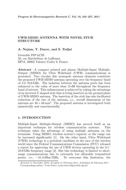
Abstract—A compact printed and planar Multiple-Input Multiple-<br />
Output (<strong>MIMO</strong>) for Ultra Wideband (<strong>UWB</strong>) communications is<br />
presented. Two circular disc monopole antenna elements constitute<br />
the proposed <strong>UWB</strong>-<strong>MIMO</strong> antenna operating over the frequency band<br />
of 3.2–10.6 GHz. The isolation between the antenna ports has been<br />
enhanced to the value of more than 15 dB throughout the frequency<br />
band of interest. This enhancement is achieved by taking the advantage<br />
of an inverted-Y shaped stub that is being inserted on the ground plane<br />
of <strong>UWB</strong>-<strong>MIMO</strong> antenna. The insertion of the stub has also facilitated<br />
reduction of the size of the antenna, i.e., overall dimensions of the<br />
antenna are 40 × 68 mm 2 . The proposed antenna is investigated both<br />
numerically and experimentally.<br />
1. INTRODUCTION<br />
Multiple-Input Multiple-Output (<strong>MIMO</strong>) has proved itself as an<br />
important technique for wireless communication systems. This<br />
technique takes the advantage of using multiple antennas on the<br />
terminals. Using <strong>MIMO</strong>, wireless system’s capacity or the range can<br />
be increased significantly [1]. On the other hand, Ultra Wideband<br />
(<strong>UWB</strong>) technology is a potential candidate in the race of the wireless<br />
world since the Federal Communications Commission (FCC) released<br />
a report for approving the use of <strong>UWB</strong> devices operating in the 3.1–<br />
10.6 GHz frequency range [2]. But this technology is limited to shortrange<br />
communications due to extremely low allowable transmitted<br />
power, i.e., −41.3 dBm/MHz. To overcome this limitation, the<br />
Received 11 December 2010, Accepted 15 February 2011, Scheduled 22 February 2011<br />
Corresponding author: Yvan Duroc (yvan.duroc@grenoble-inp.fr).
246 Najam, Duroc, and Tedjni<br />
combination of <strong>MIMO</strong> techniques with <strong>UWB</strong> technology is found to be<br />
one of the solutions. However, another bottleneck while implementing<br />
the <strong>MIMO</strong> technique for compact or portable devices arises from the<br />
poor isolation and strong mutual coupling between the closely packed<br />
antenna elements. Both mutual coupling and isolation can be improved<br />
by increasing the distance between the antenna elements but the<br />
compact size of the wireless devices limits this approach. Therefore,<br />
a good challenge appears to enhance the isolation or to reduce the<br />
mutual coupling by using some other technique.<br />
In this context, several approaches have been proposed in the<br />
literature for the narrowband systems. The matching and decoupling<br />
networks have been used to improve diversity performance of twoport<br />
antenna in [3]. In [4], a coupling element is added between two<br />
closely packed antennas to improve the isolation. A neutralization<br />
technique (folded neutralizing link and inverted U-shaped neutralizing<br />
link) to enhance port-to-port isolation is presented in [5] for two PIFA<br />
structures integrated closely. A slotted pattern based ground plane has<br />
been introduced to reduce mutual coupling between PIFA antennas<br />
in [6]. On the other hand, some research work on the same axis has<br />
also been presented for <strong>UWB</strong> applications recently. The orthogonal<br />
placement of radiating elements with respect to each other is used<br />
in [7] and [8]. The slots have been introduced on the ground plane<br />
in [9] and [10]. Three stubs have been used in [11] and one cross<br />
shaped stub is used in [12] to enhance the isolation.<br />
In this paper, a novel <strong>MIMO</strong> antenna for <strong>UWB</strong> applications is<br />
presented. The proposed antenna exploits the approach of using stubs<br />
on the ground plane in order to augment the isolation. The developed<br />
antenna is compact as compared to those presented in [11, 12]. The<br />
proposed <strong>MIMO</strong> antenna shows good impedance characteristics in the<br />
frequency band of 3.2–10.6 GHz and good isolation characteristics,<br />
so provides good diversity performance. The isolation is achieved<br />
more than 15 dB over the complete operating bandwidth. Moreover,<br />
the proposed stub has made possible to reduce the distance between<br />
the radiating elements resulting in compact <strong>UWB</strong>-<strong>MIMO</strong> antenna.<br />
The antenna is miniaturized from 43 × 80 mm 2 [13] to 40 × 68 mm 2 .<br />
The proposed antenna is being investigated both numerically and<br />
experimentally. The commercially available CST Microwave Studio<br />
is used for designing, optimizing and simulating the antenna. A vector<br />
network analyzer HP 8720ES is employed for experimental results.<br />
The remainder of this paper is described in sections as follows. In<br />
Section 2, the design of <strong>UWB</strong>-<strong>MIMO</strong> antenna with stub on the ground<br />
plane is presented. Section 3 describes the significance of the stub<br />
with parametric studies, equivalent structure and the surface current
Progress In Electromagnetics Research C, Vol. 19, 2011 247<br />
distributions. In Section 4, the radiation characteristics, time domain<br />
performance and <strong>MIMO</strong> characteristics of the proposed <strong>UWB</strong>-<strong>MIMO</strong><br />
antenna are presented and discussed. Finally, Section 5 concludes<br />
the paper with a comprehensive comparison between the <strong>UWB</strong>-<strong>MIMO</strong><br />
antenna with stub and without stub.<br />
2. <strong>ANTENNA</strong> GEOMETRY AND DESIGN<br />
The proposed <strong>UWB</strong>-<strong>MIMO</strong> antenna consisting of two radiating<br />
elements is illustrated in Fig. 1(a). Among lot of <strong>UWB</strong> antennas<br />
presented in the literature, a circular disc monopole fed by 50 Ω<br />
microstrip line [14] is used to develop the proposed <strong>UWB</strong>-<strong>MIMO</strong><br />
antenna. The selection of this antenna can be justified by its good<br />
performance, size, and ease of integration. Originally the antenna was<br />
designed using substrate of 1.5 mm thickness and a relative permittivity<br />
of 4.7 [14]. However, it is redesigned and thereafter optimized in<br />
this paper using FR4 substrate having relative permittivity of 4.4,<br />
0.8 mm thickness and 0.02 dielectric losses. The individually optimized<br />
antenna elements are placed on a single substrate and are studied again<br />
parametrically and then optimized [13]. Finally, an inverted-Y shaped<br />
stub is inserted on the middle of the ground plane to enhance the<br />
isolation between the access ports of the radiating elements as shown<br />
in Fig. 1(a). The optimized dimensions referred to Fig. 1(a) are: width<br />
of substrate W = 68 mm, length of substrate L = 40 mm, length of<br />
ground plane Lg = 11.5 mm, feed gap h = 0.3 mm, radius of each<br />
radiating element R = 12 mm, and the distance between two elements<br />
d = 34 mm.<br />
(a) (b)<br />
Figure 1. (a) Layout of <strong>UWB</strong> <strong>MIMO</strong> antenna. (b) Detailed layout<br />
of inverted-Y shaped stub.
248 Najam, Duroc, and Tedjni<br />
3. STUDIES ON INVERTED-Y SHAPED <strong>STUB</strong><br />
3.1. Principle and Equivalent Circuit<br />
The design of the inverted-Y shaped stub shown in Fig. 1(b) is being<br />
initiated on the basis of the microstrip filters theory. The gap between<br />
the stub and ground plane acts as capacitor and the side legs of stubs<br />
behave like inductors. Therefore, this structure can be thought of<br />
an equivalent LC bandstop filter. In order to get further insight into<br />
bandstop behavior of the stub, it is printed on FR4 substrate connected<br />
with two 50 Ω microstrip lines at its both ends as shown in Fig. 2. The<br />
other side of the substrate is fully metalized to form the ground plane<br />
except the area under the stub structure to get better approximation<br />
where the metal is scratched out as shown in Fig. 2.<br />
Figure 3 shows the simulated S-parameters of the stub. Initially,<br />
(a) (b)<br />
(c)<br />
Figure 2. Parametric analysis of stub dimensions. (a) Length L5. (b)<br />
Width W3. (c) Length L6. (d) Length L7, for S-parameters in the<br />
frequency range of 3.2–10.6 GHz.<br />
(d)
Progress In Electromagnetics Research C, Vol. 19, 2011 249<br />
Figure 3. Simulation setup of only stub to demonstrate its behavior.<br />
Figure 4. Filtering behavior of stub.<br />
the stub of the form of ‘pi’ is simulated, i.e., there was not middle<br />
arm. In this case, the bandstop region with the isolation of more<br />
than 10 dB is found to be starting from 6 GHz as shown in the plots.<br />
Afterwards, middle arm is added to expand the bandstop region and it<br />
was improved by the band of 1 GHz. The curves justify the bandstop<br />
behavior of the stub thus proving its equivalence to the bandstop filter.<br />
3.2. Parametric Study<br />
The inverted-Y shaped stub has been investigated in detail by<br />
performing parametric studies. The variations of S-parameters of<br />
the proposed <strong>UWB</strong>-<strong>MIMO</strong> antenna against the different dimensions<br />
of inverted-Y shaped stub within the frequency range of interest 3.2–<br />
10.6 GHz are shown in Fig. 4. The maximum values of the S11 and S21<br />
curves are plotted for nine different values of respective dimensions,<br />
i.e., L5, W3, L6 and L7 respectively in graphs a, b, c and d in Fig. 4. It<br />
should be noticed that there is no need to plot S12 and S22 as <strong>UWB</strong>-<br />
<strong>MIMO</strong> antenna has both the symmetry and the reciprocity.<br />
It is observed from the parametric study that the variations of<br />
the dimensions of stub do not respond linearly to the S-parameters.<br />
Further, the optimization is made within the suitable ranges decided
250 Najam, Duroc, and Tedjni<br />
on the basis of the parametric study. Finally, the detailed dimensions<br />
are written in Table 1, referred to Fig. 1(b).<br />
3.3. Effectiveness of Stub<br />
As the main objective of introducing the stub on the ground plane<br />
of the antenna is to enhance the isolation between the ports of<br />
the constituent radiating elements, therefore its significance can be<br />
evaluated by observing the S-parameters of the proposed <strong>UWB</strong>-<strong>MIMO</strong><br />
antenna comparing with those without stub. Fig. 5 illustrates the<br />
simulated as well as measured S-parameters of the developed <strong>UWB</strong>-<br />
<strong>MIMO</strong> antenna with and without stub. The plotted curves clearly<br />
indicate that isolation is significantly enhanced particularly in the<br />
higher band of the operating range, thanks to the stub structure, i.e.,<br />
more than 15 dB throughout the band of interest in the case of stub<br />
while more than 10 dB when there is no stub. More precisely, the<br />
simulation of the stub separately and the proposed equivalent model<br />
seem to model partially the behavior of the stub when integrated in the<br />
<strong>MIMO</strong> structure, which may explain the good isolation obtained over<br />
the band 5–11 GHz and the poor isolation over the band 3–5 GHz. The<br />
difference in the measured and simulated results can also be justified<br />
by not taking into account the connector and cable models during the<br />
simulations.<br />
Table 1. Detailed dimensions (in mm) of inverted-Y stub.<br />
W2 W3 W4 L5 L6 L7<br />
6 4 1.5 6 4 2<br />
(a) (b)<br />
Figure 5. Measured and simulated (a) reflection coefficients and (b)<br />
transmission coefficients of the proposed antenna with and without<br />
stub.
Progress In Electromagnetics Research C, Vol. 19, 2011 251<br />
(a) 3.5 GHz (b) 3.5 GHz<br />
(c) 7.0 GHz (d) 7.0 GHz<br />
(e) 9.5 GHz (f) 9.5 GHz<br />
Figure 6. Surface current distributions of antenna: (a), (c) and (e)<br />
with stub; (b), (d) and (f) without stub.<br />
(a) (b)<br />
Figure 7. Radiation patterns simulated at frequencies of 3.5 GHz,<br />
7.0 GHz and 9.5 GHz.
252 Najam, Duroc, and Tedjni<br />
To further elaborate the effectiveness of the insertion of the stub,<br />
the degree of isolation in the proposed antenna can be observed by<br />
presenting surface current distributions. Fig. 6 shows the current<br />
distributions with and without stub at three frequencies 3.5 GHz,<br />
7 GHz and 9.5 GHz when left radiating element is excited while the<br />
right radiating element is terminated with a load impedance of 50 Ω.<br />
The effects of the stub on the current distributions can clearly be<br />
noticed by comparing with those without stub. The current is<br />
absorbed by stub and thus it ameliorates the port isolation between two<br />
monopoles. In addition to this, it is worth mentioning that the mutual<br />
coupling is also reduced taking advantage of this stub by looking into<br />
these current distributions.<br />
4. PERFORMANCE OF <strong>UWB</strong>-<strong>MIMO</strong> <strong>ANTENNA</strong><br />
4.1. Radiation Characteristics<br />
The designed antenna is placed in XY-plane with Z-axis coming<br />
out of the page (Fig. 1(a)). The radiation patterns of the antenna<br />
are simulated at the frequencies of 3.5, 7.0 and 9.5 GHz in Y OZplane<br />
(E-plane) and XOZ-plane (H-plane). Fig. 7 presents the<br />
radiation patterns of the left radiating element of antenna in the polar<br />
coordinates. The results show that antenna behaves nearly omnidirectional<br />
in H-plane. The humps and notches are observed in Eplane<br />
due to uneven and complex distributions of the current.<br />
Figure 8 gives the plots of maximum absolute gains and the total<br />
efficiencies of the proposed antenna compared to the antenna without<br />
stub. Looking into these plots, it can be noticed that gain is being<br />
reduced by an average of about 1 dBi when the stub is inserted. <strong>UWB</strong><br />
(a) (b)<br />
Figure 8. Simulated (a) absolute gains and (b) total efficiencies of<br />
the proposed antenna.
Progress In Electromagnetics Research C, Vol. 19, 2011 253<br />
systems require low variation in gain values over the operating range<br />
of the antenna. From Fig. 8(a), it can be noticed that the variation<br />
in the gain values is found to be less than 2.5 dBi that is quite good.<br />
Further, the variation in efficiencies as shown in Fig. 8(b) throughout<br />
the bandwidth is also not more than 15%.<br />
4.2. Time Domain Performance<br />
The radiating elements of the designed <strong>UWB</strong>-<strong>MIMO</strong> antenna are<br />
also characterized for its time domain performance to confirm their<br />
capability for <strong>UWB</strong> operations. The radiating elements are fed by<br />
the fifth derivative of Gaussian pulse of 0.13 ns wide where the pulse<br />
width is measured at 50% of the maximum amplitude. The selection<br />
of this excitation pulse can be justified by its spectrum that efficiently<br />
meets the requirements of FCC approved <strong>UWB</strong> spectral mask [15].<br />
The time domain impulse response of the left element of antenna with<br />
and without the stub in the far-field zone is shown in Fig. 9(a). It can<br />
be seen from the figure that the pulse of width of 0.185 ns is radiated<br />
from antenna. Thus, it indicates good time domain response and it can<br />
be further justified by group delay shown in Fig. 9(b). The variation of<br />
group delay is found to be less than 1 ns showing good phase linearity<br />
and thus it fulfils the requirement for <strong>UWB</strong> operations.<br />
4.3. <strong>MIMO</strong> Characteristics<br />
It is evident that <strong>MIMO</strong> antennas are required to be characterized<br />
for their diversity performance. In a diversity system, it is usual<br />
that signals can be correlated to some extent, hence measuring the<br />
degree of correlation between two antenna elements becomes important<br />
(a) (b)<br />
Figure 9. Time domain characteristics.
254 Najam, Duroc, and Tedjni<br />
to evaluate the diversity capabilities for <strong>MIMO</strong> applications. It is<br />
required to minimize the correlation because the relationship of the<br />
correlation with diversity gain is that the lower the correlation, the<br />
higher will be the diversity gain and vice versa. The correlation<br />
coefficient can be calculated from radiation patterns or scattering<br />
parameters. For a simple two-port network, assuming uniform<br />
multipath environment, the envelope correlation (ρ), simply square of<br />
the correlation coefficient, can be calculated conveniently and quickly<br />
from S-parameters [16], using Eq. (1) given as<br />
�<br />
�<br />
�<br />
�<br />
ρ = �<br />
S<br />
�<br />
�<br />
�<br />
∗ 11S12 + S∗ 21S22 ��<br />
1 − |S11| 2 − |S21| 2<br />
� ��<br />
· 1 − |S22| 2 − |S12| 2<br />
�<br />
�2<br />
�<br />
�<br />
��<br />
�<br />
�<br />
�<br />
(1)<br />
The envelope correlation coefficient is shown in Fig. 10(a). It is<br />
calculated from the measured S-parameters of the proposed antenna<br />
using Eq. (1). As per results, very low value of correlation coefficient<br />
ensures high diversity gain.<br />
(a) (b)<br />
Figure 10. <strong>MIMO</strong> characteristics (a) envelope correlation and (b)<br />
TARC.<br />
Another parameter, Total Active Reflection Coefficient (TARC)<br />
is worthy to be considered while evaluating the performance of <strong>MIMO</strong><br />
antennas. This parameter provides a more meaningful measure as<br />
compared to simple reflection coefficient as it takes the mutual effects<br />
into account as well [17]. From the definition of TARC in [17], it can<br />
be determined for 2 × 2 <strong>MIMO</strong> system using Eq. (2) given as<br />
�<br />
Γ ′ a =<br />
|S11 + S12e jθ | 2 + |S21 + S22e jθ | 2<br />
2<br />
(2)
Progress In Electromagnetics Research C, Vol. 19, 2011 255<br />
Table 2. Performance comparisons of antennas with and without stub.<br />
Parameters Ref. [13] This article<br />
Layout<br />
Constituent Elements Circular disc Circular disc<br />
Feeding configuration Parallel Parallel<br />
Impedance BW (GHz) 3.1 – 10.6 3.1 – 10.6<br />
Gain variation (dBi) < 3.5 < 2.5<br />
Total efficiency > 75 % 70 % – 85 %<br />
Group delay (ns) 2.2 1<br />
Isolation (dB) > 11 > 15<br />
Correlation coefficient (dB) < - 15 < - 20<br />
TARC (dB) < -10 < - 9.5<br />
Size (mm²) 43 × 80 40 × 68<br />
The proposed antenna system is also using two antenna elements;<br />
hence Eq. (2) can be applied here to calculate TARC. The variable<br />
angle is related to the phase of excitation signal. The hundred<br />
independent identically distributed (i.i.d.) and randomly phased<br />
excitation vectors have been used to calculate average TARC assuming<br />
Gaussian distribution and multipath spread in rich scattered channel<br />
and taking measures S-parameters. TARC is calculated at each<br />
random phase using Eq. (2) and its average is shown in Fig. 10(b).<br />
It is clear that the impedance bandwidth covers the same band in this<br />
case too.<br />
5. CONCLUSION<br />
A printed compact <strong>MIMO</strong> antenna for Ultra-Wideband applications<br />
is designed and developed. The isolation is enhanced by adding an<br />
inverted-Y shaped stub on the ground plane. The significant increase<br />
in port isolation as well as reduction in mutual coupling by using<br />
the stub has helped in miniaturizing the antenna. The developed<br />
<strong>UWB</strong>-<strong>MIMO</strong> antenna is more compact and efficient as compared to<br />
<strong>UWB</strong>-<strong>MIMO</strong> antenna presented in [12] with the same topology but<br />
not using the stub. It is also tested experimentally to ensure its<br />
performance. Further, a tabulated comparison between the antenna<br />
with stub proposed in this paper and the antenna without stub
256 Najam, Duroc, and Tedjni<br />
proposed in [13] is presented in Table 2.<br />
From this tabulated comparison, first of all, the reduction of the<br />
antenna size should be noticed. Secondly, it is very clear that isolation<br />
is enhanced even with reduced size. The gain of the antenna with<br />
stub is decreased by 1 dBi compared with the antenna without stub,<br />
however the variation in gain values remain nearly the same. The<br />
efficiency is significantly increased in the higher band (6.5–10.6 GHz)<br />
and it is obvious due to enhancement of isolation in this region by more<br />
than 10 dB. The time domain performance is better than the case when<br />
the stub is not inserted.<br />
It should be noted that the global performance of the proposed<br />
antenna could be improved using another substrate with a smaller loss<br />
tangent and having more stable reponse at higher frequencies such<br />
as Duroid instead of FR4 (low-cost substrate). Finally, it can be<br />
concluded that the proposed antenna shows good performance taking<br />
advantage of inverted-Y shaped stub and is capable of employing<br />
in portable devices using <strong>UWB</strong> technology combined with <strong>MIMO</strong><br />
techniques.<br />
REFERENCES<br />
1. Foschini, G. J. and M. J. Gans, “On limits of wireless<br />
communications in a fading environment when using multiple<br />
antennas,” Wireless Personal Communications, Vol. 6, No. 3, 311–<br />
335, 1998.<br />
2. Federal Communication Commission (FCC), “Revision of part 15<br />
of the commissions rules regarding ultra-wideband transmission<br />
systems,” ET Docket 98–153, FCC 02–48, First Report and Order,<br />
Apr. 2002.<br />
3. Dossche, S., S. Blanch, and J. Romeu, “Optimum antenna<br />
matching to minimize signal correlation on a two port antenna<br />
diversity system,” Electronic Letters, Vol. 40, No. 19, 1164–1165,<br />
Sep. 2004.<br />
4. Mak, A. C. K., C. R. Rowell, and R. D. Murch, “Isolation<br />
enhancement between two closely packed antennas,” IEEE<br />
Transactions on Antennas and Propagation, Vol. 56, No. 11, 3411–<br />
3419, Nov. 2008.<br />
5. Chebihi, A., C. Luxey, A. Diallo, P. Le Thuc, and R. Staraj, “A<br />
novel isolation technique for closely spaced pifas for umts mobile<br />
phones,” IEEE Antennas and Wireless Propagation Letters,<br />
Vol. 7, 665–668, Nov. 2008.<br />
6. Chiu, C.-Y., C.-H. Cheng, R. D. Murch, and C. R. Rowell,<br />
“Reduction of mutual coupling between closely-packed antenna
Progress In Electromagnetics Research C, Vol. 19, 2011 257<br />
elements,” IEEE Transactions on Antennas and Propagation,<br />
Vol. 55, No. 6, 1732–1738, Jun. 2007.<br />
7. Najam, A. I., Y. Duroc, J. F. A. Leao, and S. Tedjini, “A<br />
novel collocated antennas system for <strong>UWB</strong>-<strong>MIMO</strong> applications,”<br />
Proc. IEEE International Radio and Wireless Symposium, 368–<br />
371, Jan. 2009.<br />
8. Wong, K.-L., S.-W. Su, and Y.-L. Kuo, “A printed ultra-wideband<br />
diversity monopole antenna,” Microwave Optical Technology<br />
Letters, Vol. 38, No. 4, 257–259, 2003.<br />
9. Liu, L., H. Zhao, T. S. P. See, and Z.-N. Chen, “A printed<br />
ultra-wideband diversity antenna,” Proc. IEEE International<br />
Conference on Ultra-Wideband, 351–356, Sep. 2006.<br />
10. Kim, I., C. W. Jung, Y. Kim, and Y. Kim, “Low-profile wideband<br />
<strong>MIMO</strong> antenna with suppressing mutual coupling between two<br />
antennas,” Microwave Optical Technology Letters, Vol. 50, No. 5,<br />
1336–1339, May 2008.<br />
11. Hong, S., K. Chung, J. Lee, S. Jung, S. S. Lee, and J. Choi,<br />
“Design of a diversity antenna with stubs for <strong>UWB</strong> applications,”<br />
Microwave Optical Technology Letters, Vol. 50, No. 5, 1352–1356,<br />
May 2008.<br />
12. Cheng, Y., W. J. Lu, C. H. Cheng, W. Cao, and Y. Li,<br />
“Printed diversity antenna with cross shape stub for ultrawideband<br />
applications,” Proc. IEEE International Conference<br />
Communications Systems, 813–816, Nov. 2008.<br />
13. Najam, A. I., Y. Duroc, and S. Tedjini, “Design and analysis<br />
of <strong>MIMO</strong> antennas for <strong>UWB</strong> communications,” Proc. European<br />
Conference on Antennas and Propagation, Apr. 2010.<br />
14. Choi, S. H., J. K. Park, S. K. Kim, and J. Y. Park, “A new<br />
ultrawideband antenna for <strong>UWB</strong> applications,” Microwave and<br />
Optical Technology Letters, Vol. 40, No. 5, 399–401, May 2004.<br />
15. Sheng, H., P. Orlik, A. M. Haimovich, L. J. Cimini, and<br />
J. Zhang, “On the spectral and power requirements for ultrawideband<br />
transmission,” Proc. IEEE International Conference on<br />
Communications, Vol. 1, 738–742, May 2003.<br />
16. Salonen, I. and P. Vainikainen, “Estimation of signal correlation<br />
in antenna arrays,” Proc. International Symposium on Antennas,<br />
Vol. 2, 383–386, Nov. 2002.<br />
17. Manteghi, M. and Y. Rahmat-Samii, “Multiport characteristics<br />
of a wide-band cavity backed annular patch antenna for<br />
multipolarization operations,” IEEE Transactions on Antennas<br />
and Propagation, Vol. 53, No. 1, 466–474, Jan. 2005.