UWB-MIMO ANTENNA WITH NOVEL STUB STRUCTURE A ... - PIER
UWB-MIMO ANTENNA WITH NOVEL STUB STRUCTURE A ... - PIER
UWB-MIMO ANTENNA WITH NOVEL STUB STRUCTURE A ... - PIER

Create successful ePaper yourself
Turn your PDF publications into a flip-book with our unique Google optimized e-Paper software.
250 Najam, Duroc, and Tedjni<br />
on the basis of the parametric study. Finally, the detailed dimensions<br />
are written in Table 1, referred to Fig. 1(b).<br />
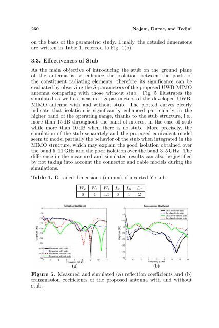
3.3. Effectiveness of Stub<br />
As the main objective of introducing the stub on the ground plane<br />
of the antenna is to enhance the isolation between the ports of<br />
the constituent radiating elements, therefore its significance can be<br />
evaluated by observing the S-parameters of the proposed <strong>UWB</strong>-<strong>MIMO</strong><br />
antenna comparing with those without stub. Fig. 5 illustrates the<br />
simulated as well as measured S-parameters of the developed <strong>UWB</strong>-<br />
<strong>MIMO</strong> antenna with and without stub. The plotted curves clearly<br />
indicate that isolation is significantly enhanced particularly in the<br />
higher band of the operating range, thanks to the stub structure, i.e.,<br />
more than 15 dB throughout the band of interest in the case of stub<br />
while more than 10 dB when there is no stub. More precisely, the<br />
simulation of the stub separately and the proposed equivalent model<br />
seem to model partially the behavior of the stub when integrated in the<br />
<strong>MIMO</strong> structure, which may explain the good isolation obtained over<br />
the band 5–11 GHz and the poor isolation over the band 3–5 GHz. The<br />
difference in the measured and simulated results can also be justified<br />
by not taking into account the connector and cable models during the<br />
simulations.<br />
Table 1. Detailed dimensions (in mm) of inverted-Y stub.<br />
W2 W3 W4 L5 L6 L7<br />
6 4 1.5 6 4 2<br />
(a) (b)<br />
Figure 5. Measured and simulated (a) reflection coefficients and (b)<br />
transmission coefficients of the proposed antenna with and without<br />
stub.