UWB-MIMO ANTENNA WITH NOVEL STUB STRUCTURE A ... - PIER
UWB-MIMO ANTENNA WITH NOVEL STUB STRUCTURE A ... - PIER
UWB-MIMO ANTENNA WITH NOVEL STUB STRUCTURE A ... - PIER

Create successful ePaper yourself
Turn your PDF publications into a flip-book with our unique Google optimized e-Paper software.
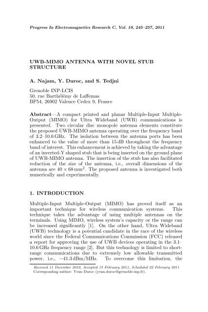
Progress In Electromagnetics Research C, Vol. 19, 245–257, 2011<br />
<strong>UWB</strong>-<strong>MIMO</strong> <strong>ANTENNA</strong> <strong>WITH</strong> <strong>NOVEL</strong> <strong>STUB</strong><br />
<strong>STRUCTURE</strong><br />
A. Najam, Y. Duroc, and S. Tedjni<br />
Grenoble INP-LCIS<br />
50, rue Barthélémy de Laffemas<br />
BP54, 26902 Valence Cedex 9, France<br />
Abstract—A compact printed and planar Multiple-Input Multiple-<br />
Output (<strong>MIMO</strong>) for Ultra Wideband (<strong>UWB</strong>) communications is<br />
presented. Two circular disc monopole antenna elements constitute<br />
the proposed <strong>UWB</strong>-<strong>MIMO</strong> antenna operating over the frequency band<br />
of 3.2–10.6 GHz. The isolation between the antenna ports has been<br />
enhanced to the value of more than 15 dB throughout the frequency<br />
band of interest. This enhancement is achieved by taking the advantage<br />
of an inverted-Y shaped stub that is being inserted on the ground plane<br />
of <strong>UWB</strong>-<strong>MIMO</strong> antenna. The insertion of the stub has also facilitated<br />
reduction of the size of the antenna, i.e., overall dimensions of the<br />
antenna are 40 × 68 mm 2 . The proposed antenna is investigated both<br />
numerically and experimentally.<br />
1. INTRODUCTION<br />
Multiple-Input Multiple-Output (<strong>MIMO</strong>) has proved itself as an<br />
important technique for wireless communication systems. This<br />
technique takes the advantage of using multiple antennas on the<br />
terminals. Using <strong>MIMO</strong>, wireless system’s capacity or the range can<br />
be increased significantly [1]. On the other hand, Ultra Wideband<br />
(<strong>UWB</strong>) technology is a potential candidate in the race of the wireless<br />
world since the Federal Communications Commission (FCC) released<br />
a report for approving the use of <strong>UWB</strong> devices operating in the 3.1–<br />
10.6 GHz frequency range [2]. But this technology is limited to shortrange<br />
communications due to extremely low allowable transmitted<br />
power, i.e., −41.3 dBm/MHz. To overcome this limitation, the<br />
Received 11 December 2010, Accepted 15 February 2011, Scheduled 22 February 2011<br />
Corresponding author: Yvan Duroc (yvan.duroc@grenoble-inp.fr).
246 Najam, Duroc, and Tedjni<br />
combination of <strong>MIMO</strong> techniques with <strong>UWB</strong> technology is found to be<br />
one of the solutions. However, another bottleneck while implementing<br />
the <strong>MIMO</strong> technique for compact or portable devices arises from the<br />
poor isolation and strong mutual coupling between the closely packed<br />
antenna elements. Both mutual coupling and isolation can be improved<br />
by increasing the distance between the antenna elements but the<br />
compact size of the wireless devices limits this approach. Therefore,<br />
a good challenge appears to enhance the isolation or to reduce the<br />
mutual coupling by using some other technique.<br />
In this context, several approaches have been proposed in the<br />
literature for the narrowband systems. The matching and decoupling<br />
networks have been used to improve diversity performance of twoport<br />
antenna in [3]. In [4], a coupling element is added between two<br />
closely packed antennas to improve the isolation. A neutralization<br />
technique (folded neutralizing link and inverted U-shaped neutralizing<br />
link) to enhance port-to-port isolation is presented in [5] for two PIFA<br />
structures integrated closely. A slotted pattern based ground plane has<br />
been introduced to reduce mutual coupling between PIFA antennas<br />
in [6]. On the other hand, some research work on the same axis has<br />
also been presented for <strong>UWB</strong> applications recently. The orthogonal<br />
placement of radiating elements with respect to each other is used<br />
in [7] and [8]. The slots have been introduced on the ground plane<br />
in [9] and [10]. Three stubs have been used in [11] and one cross<br />
shaped stub is used in [12] to enhance the isolation.<br />
In this paper, a novel <strong>MIMO</strong> antenna for <strong>UWB</strong> applications is<br />
presented. The proposed antenna exploits the approach of using stubs<br />
on the ground plane in order to augment the isolation. The developed<br />
antenna is compact as compared to those presented in [11, 12]. The<br />
proposed <strong>MIMO</strong> antenna shows good impedance characteristics in the<br />
frequency band of 3.2–10.6 GHz and good isolation characteristics,<br />
so provides good diversity performance. The isolation is achieved<br />
more than 15 dB over the complete operating bandwidth. Moreover,<br />
the proposed stub has made possible to reduce the distance between<br />
the radiating elements resulting in compact <strong>UWB</strong>-<strong>MIMO</strong> antenna.<br />
The antenna is miniaturized from 43 × 80 mm 2 [13] to 40 × 68 mm 2 .<br />
The proposed antenna is being investigated both numerically and<br />
experimentally. The commercially available CST Microwave Studio<br />
is used for designing, optimizing and simulating the antenna. A vector<br />
network analyzer HP 8720ES is employed for experimental results.<br />
The remainder of this paper is described in sections as follows. In<br />
Section 2, the design of <strong>UWB</strong>-<strong>MIMO</strong> antenna with stub on the ground<br />
plane is presented. Section 3 describes the significance of the stub<br />
with parametric studies, equivalent structure and the surface current
Progress In Electromagnetics Research C, Vol. 19, 2011 247<br />
distributions. In Section 4, the radiation characteristics, time domain<br />
performance and <strong>MIMO</strong> characteristics of the proposed <strong>UWB</strong>-<strong>MIMO</strong><br />
antenna are presented and discussed. Finally, Section 5 concludes<br />
the paper with a comprehensive comparison between the <strong>UWB</strong>-<strong>MIMO</strong><br />
antenna with stub and without stub.<br />
2. <strong>ANTENNA</strong> GEOMETRY AND DESIGN<br />
The proposed <strong>UWB</strong>-<strong>MIMO</strong> antenna consisting of two radiating<br />
elements is illustrated in Fig. 1(a). Among lot of <strong>UWB</strong> antennas<br />
presented in the literature, a circular disc monopole fed by 50 Ω<br />
microstrip line [14] is used to develop the proposed <strong>UWB</strong>-<strong>MIMO</strong><br />
antenna. The selection of this antenna can be justified by its good<br />
performance, size, and ease of integration. Originally the antenna was<br />
designed using substrate of 1.5 mm thickness and a relative permittivity<br />
of 4.7 [14]. However, it is redesigned and thereafter optimized in<br />
this paper using FR4 substrate having relative permittivity of 4.4,<br />
0.8 mm thickness and 0.02 dielectric losses. The individually optimized<br />
antenna elements are placed on a single substrate and are studied again<br />
parametrically and then optimized [13]. Finally, an inverted-Y shaped<br />
stub is inserted on the middle of the ground plane to enhance the<br />
isolation between the access ports of the radiating elements as shown<br />
in Fig. 1(a). The optimized dimensions referred to Fig. 1(a) are: width<br />
of substrate W = 68 mm, length of substrate L = 40 mm, length of<br />
ground plane Lg = 11.5 mm, feed gap h = 0.3 mm, radius of each<br />
radiating element R = 12 mm, and the distance between two elements<br />
d = 34 mm.<br />
(a) (b)<br />
Figure 1. (a) Layout of <strong>UWB</strong> <strong>MIMO</strong> antenna. (b) Detailed layout<br />
of inverted-Y shaped stub.
248 Najam, Duroc, and Tedjni<br />
3. STUDIES ON INVERTED-Y SHAPED <strong>STUB</strong><br />
3.1. Principle and Equivalent Circuit<br />
The design of the inverted-Y shaped stub shown in Fig. 1(b) is being<br />
initiated on the basis of the microstrip filters theory. The gap between<br />
the stub and ground plane acts as capacitor and the side legs of stubs<br />
behave like inductors. Therefore, this structure can be thought of<br />
an equivalent LC bandstop filter. In order to get further insight into<br />
bandstop behavior of the stub, it is printed on FR4 substrate connected<br />
with two 50 Ω microstrip lines at its both ends as shown in Fig. 2. The<br />
other side of the substrate is fully metalized to form the ground plane<br />
except the area under the stub structure to get better approximation<br />
where the metal is scratched out as shown in Fig. 2.<br />
Figure 3 shows the simulated S-parameters of the stub. Initially,<br />
(a) (b)<br />
(c)<br />
Figure 2. Parametric analysis of stub dimensions. (a) Length L5. (b)<br />
Width W3. (c) Length L6. (d) Length L7, for S-parameters in the<br />
frequency range of 3.2–10.6 GHz.<br />
(d)
Progress In Electromagnetics Research C, Vol. 19, 2011 249<br />
Figure 3. Simulation setup of only stub to demonstrate its behavior.<br />
Figure 4. Filtering behavior of stub.<br />
the stub of the form of ‘pi’ is simulated, i.e., there was not middle<br />
arm. In this case, the bandstop region with the isolation of more<br />
than 10 dB is found to be starting from 6 GHz as shown in the plots.<br />
Afterwards, middle arm is added to expand the bandstop region and it<br />
was improved by the band of 1 GHz. The curves justify the bandstop<br />
behavior of the stub thus proving its equivalence to the bandstop filter.<br />
3.2. Parametric Study<br />
The inverted-Y shaped stub has been investigated in detail by<br />
performing parametric studies. The variations of S-parameters of<br />
the proposed <strong>UWB</strong>-<strong>MIMO</strong> antenna against the different dimensions<br />
of inverted-Y shaped stub within the frequency range of interest 3.2–<br />
10.6 GHz are shown in Fig. 4. The maximum values of the S11 and S21<br />
curves are plotted for nine different values of respective dimensions,<br />
i.e., L5, W3, L6 and L7 respectively in graphs a, b, c and d in Fig. 4. It<br />
should be noticed that there is no need to plot S12 and S22 as <strong>UWB</strong>-<br />
<strong>MIMO</strong> antenna has both the symmetry and the reciprocity.<br />
It is observed from the parametric study that the variations of<br />
the dimensions of stub do not respond linearly to the S-parameters.<br />
Further, the optimization is made within the suitable ranges decided
250 Najam, Duroc, and Tedjni<br />
on the basis of the parametric study. Finally, the detailed dimensions<br />
are written in Table 1, referred to Fig. 1(b).<br />
3.3. Effectiveness of Stub<br />
As the main objective of introducing the stub on the ground plane<br />
of the antenna is to enhance the isolation between the ports of<br />
the constituent radiating elements, therefore its significance can be<br />
evaluated by observing the S-parameters of the proposed <strong>UWB</strong>-<strong>MIMO</strong><br />
antenna comparing with those without stub. Fig. 5 illustrates the<br />
simulated as well as measured S-parameters of the developed <strong>UWB</strong>-<br />
<strong>MIMO</strong> antenna with and without stub. The plotted curves clearly<br />
indicate that isolation is significantly enhanced particularly in the<br />
higher band of the operating range, thanks to the stub structure, i.e.,<br />
more than 15 dB throughout the band of interest in the case of stub<br />
while more than 10 dB when there is no stub. More precisely, the<br />
simulation of the stub separately and the proposed equivalent model<br />
seem to model partially the behavior of the stub when integrated in the<br />
<strong>MIMO</strong> structure, which may explain the good isolation obtained over<br />
the band 5–11 GHz and the poor isolation over the band 3–5 GHz. The<br />
difference in the measured and simulated results can also be justified<br />
by not taking into account the connector and cable models during the<br />
simulations.<br />
Table 1. Detailed dimensions (in mm) of inverted-Y stub.<br />
W2 W3 W4 L5 L6 L7<br />
6 4 1.5 6 4 2<br />
(a) (b)<br />
Figure 5. Measured and simulated (a) reflection coefficients and (b)<br />
transmission coefficients of the proposed antenna with and without<br />
stub.
Progress In Electromagnetics Research C, Vol. 19, 2011 251<br />
(a) 3.5 GHz (b) 3.5 GHz<br />
(c) 7.0 GHz (d) 7.0 GHz<br />
(e) 9.5 GHz (f) 9.5 GHz<br />
Figure 6. Surface current distributions of antenna: (a), (c) and (e)<br />
with stub; (b), (d) and (f) without stub.<br />
(a) (b)<br />
Figure 7. Radiation patterns simulated at frequencies of 3.5 GHz,<br />
7.0 GHz and 9.5 GHz.
252 Najam, Duroc, and Tedjni<br />
To further elaborate the effectiveness of the insertion of the stub,<br />
the degree of isolation in the proposed antenna can be observed by<br />
presenting surface current distributions. Fig. 6 shows the current<br />
distributions with and without stub at three frequencies 3.5 GHz,<br />
7 GHz and 9.5 GHz when left radiating element is excited while the<br />
right radiating element is terminated with a load impedance of 50 Ω.<br />
The effects of the stub on the current distributions can clearly be<br />
noticed by comparing with those without stub. The current is<br />
absorbed by stub and thus it ameliorates the port isolation between two<br />
monopoles. In addition to this, it is worth mentioning that the mutual<br />
coupling is also reduced taking advantage of this stub by looking into<br />
these current distributions.<br />
4. PERFORMANCE OF <strong>UWB</strong>-<strong>MIMO</strong> <strong>ANTENNA</strong><br />
4.1. Radiation Characteristics<br />
The designed antenna is placed in XY-plane with Z-axis coming<br />
out of the page (Fig. 1(a)). The radiation patterns of the antenna<br />
are simulated at the frequencies of 3.5, 7.0 and 9.5 GHz in Y OZplane<br />
(E-plane) and XOZ-plane (H-plane). Fig. 7 presents the<br />
radiation patterns of the left radiating element of antenna in the polar<br />
coordinates. The results show that antenna behaves nearly omnidirectional<br />
in H-plane. The humps and notches are observed in Eplane<br />
due to uneven and complex distributions of the current.<br />
Figure 8 gives the plots of maximum absolute gains and the total<br />
efficiencies of the proposed antenna compared to the antenna without<br />
stub. Looking into these plots, it can be noticed that gain is being<br />
reduced by an average of about 1 dBi when the stub is inserted. <strong>UWB</strong><br />
(a) (b)<br />
Figure 8. Simulated (a) absolute gains and (b) total efficiencies of<br />
the proposed antenna.
Progress In Electromagnetics Research C, Vol. 19, 2011 253<br />
systems require low variation in gain values over the operating range<br />
of the antenna. From Fig. 8(a), it can be noticed that the variation<br />
in the gain values is found to be less than 2.5 dBi that is quite good.<br />
Further, the variation in efficiencies as shown in Fig. 8(b) throughout<br />
the bandwidth is also not more than 15%.<br />
4.2. Time Domain Performance<br />
The radiating elements of the designed <strong>UWB</strong>-<strong>MIMO</strong> antenna are<br />
also characterized for its time domain performance to confirm their<br />
capability for <strong>UWB</strong> operations. The radiating elements are fed by<br />
the fifth derivative of Gaussian pulse of 0.13 ns wide where the pulse<br />
width is measured at 50% of the maximum amplitude. The selection<br />
of this excitation pulse can be justified by its spectrum that efficiently<br />
meets the requirements of FCC approved <strong>UWB</strong> spectral mask [15].<br />
The time domain impulse response of the left element of antenna with<br />
and without the stub in the far-field zone is shown in Fig. 9(a). It can<br />
be seen from the figure that the pulse of width of 0.185 ns is radiated<br />
from antenna. Thus, it indicates good time domain response and it can<br />
be further justified by group delay shown in Fig. 9(b). The variation of<br />
group delay is found to be less than 1 ns showing good phase linearity<br />
and thus it fulfils the requirement for <strong>UWB</strong> operations.<br />
4.3. <strong>MIMO</strong> Characteristics<br />
It is evident that <strong>MIMO</strong> antennas are required to be characterized<br />
for their diversity performance. In a diversity system, it is usual<br />
that signals can be correlated to some extent, hence measuring the<br />
degree of correlation between two antenna elements becomes important<br />
(a) (b)<br />
Figure 9. Time domain characteristics.
254 Najam, Duroc, and Tedjni<br />
to evaluate the diversity capabilities for <strong>MIMO</strong> applications. It is<br />
required to minimize the correlation because the relationship of the<br />
correlation with diversity gain is that the lower the correlation, the<br />
higher will be the diversity gain and vice versa. The correlation<br />
coefficient can be calculated from radiation patterns or scattering<br />
parameters. For a simple two-port network, assuming uniform<br />
multipath environment, the envelope correlation (ρ), simply square of<br />
the correlation coefficient, can be calculated conveniently and quickly<br />
from S-parameters [16], using Eq. (1) given as<br />
�<br />
�<br />
�<br />
�<br />
ρ = �<br />
S<br />
�<br />
�<br />
�<br />
∗ 11S12 + S∗ 21S22 ��<br />
1 − |S11| 2 − |S21| 2<br />
� ��<br />
· 1 − |S22| 2 − |S12| 2<br />
�<br />
�2<br />
�<br />
�<br />
��<br />
�<br />
�<br />
�<br />
(1)<br />
The envelope correlation coefficient is shown in Fig. 10(a). It is<br />
calculated from the measured S-parameters of the proposed antenna<br />
using Eq. (1). As per results, very low value of correlation coefficient<br />
ensures high diversity gain.<br />
(a) (b)<br />
Figure 10. <strong>MIMO</strong> characteristics (a) envelope correlation and (b)<br />
TARC.<br />
Another parameter, Total Active Reflection Coefficient (TARC)<br />
is worthy to be considered while evaluating the performance of <strong>MIMO</strong><br />
antennas. This parameter provides a more meaningful measure as<br />
compared to simple reflection coefficient as it takes the mutual effects<br />
into account as well [17]. From the definition of TARC in [17], it can<br />
be determined for 2 × 2 <strong>MIMO</strong> system using Eq. (2) given as<br />
�<br />
Γ ′ a =<br />
|S11 + S12e jθ | 2 + |S21 + S22e jθ | 2<br />
2<br />
(2)
Progress In Electromagnetics Research C, Vol. 19, 2011 255<br />
Table 2. Performance comparisons of antennas with and without stub.<br />
Parameters Ref. [13] This article<br />
Layout<br />
Constituent Elements Circular disc Circular disc<br />
Feeding configuration Parallel Parallel<br />
Impedance BW (GHz) 3.1 – 10.6 3.1 – 10.6<br />
Gain variation (dBi) < 3.5 < 2.5<br />
Total efficiency > 75 % 70 % – 85 %<br />
Group delay (ns) 2.2 1<br />
Isolation (dB) > 11 > 15<br />
Correlation coefficient (dB) < - 15 < - 20<br />
TARC (dB) < -10 < - 9.5<br />
Size (mm²) 43 × 80 40 × 68<br />
The proposed antenna system is also using two antenna elements;<br />
hence Eq. (2) can be applied here to calculate TARC. The variable<br />
angle is related to the phase of excitation signal. The hundred<br />
independent identically distributed (i.i.d.) and randomly phased<br />
excitation vectors have been used to calculate average TARC assuming<br />
Gaussian distribution and multipath spread in rich scattered channel<br />
and taking measures S-parameters. TARC is calculated at each<br />
random phase using Eq. (2) and its average is shown in Fig. 10(b).<br />
It is clear that the impedance bandwidth covers the same band in this<br />
case too.<br />
5. CONCLUSION<br />
A printed compact <strong>MIMO</strong> antenna for Ultra-Wideband applications<br />
is designed and developed. The isolation is enhanced by adding an<br />
inverted-Y shaped stub on the ground plane. The significant increase<br />
in port isolation as well as reduction in mutual coupling by using<br />
the stub has helped in miniaturizing the antenna. The developed<br />
<strong>UWB</strong>-<strong>MIMO</strong> antenna is more compact and efficient as compared to<br />
<strong>UWB</strong>-<strong>MIMO</strong> antenna presented in [12] with the same topology but<br />
not using the stub. It is also tested experimentally to ensure its<br />
performance. Further, a tabulated comparison between the antenna<br />
with stub proposed in this paper and the antenna without stub
256 Najam, Duroc, and Tedjni<br />
proposed in [13] is presented in Table 2.<br />
From this tabulated comparison, first of all, the reduction of the<br />
antenna size should be noticed. Secondly, it is very clear that isolation<br />
is enhanced even with reduced size. The gain of the antenna with<br />
stub is decreased by 1 dBi compared with the antenna without stub,<br />
however the variation in gain values remain nearly the same. The<br />
efficiency is significantly increased in the higher band (6.5–10.6 GHz)<br />
and it is obvious due to enhancement of isolation in this region by more<br />
than 10 dB. The time domain performance is better than the case when<br />
the stub is not inserted.<br />
It should be noted that the global performance of the proposed<br />
antenna could be improved using another substrate with a smaller loss<br />
tangent and having more stable reponse at higher frequencies such<br />
as Duroid instead of FR4 (low-cost substrate). Finally, it can be<br />
concluded that the proposed antenna shows good performance taking<br />
advantage of inverted-Y shaped stub and is capable of employing<br />
in portable devices using <strong>UWB</strong> technology combined with <strong>MIMO</strong><br />
techniques.<br />
REFERENCES<br />
1. Foschini, G. J. and M. J. Gans, “On limits of wireless<br />
communications in a fading environment when using multiple<br />
antennas,” Wireless Personal Communications, Vol. 6, No. 3, 311–<br />
335, 1998.<br />
2. Federal Communication Commission (FCC), “Revision of part 15<br />
of the commissions rules regarding ultra-wideband transmission<br />
systems,” ET Docket 98–153, FCC 02–48, First Report and Order,<br />
Apr. 2002.<br />
3. Dossche, S., S. Blanch, and J. Romeu, “Optimum antenna<br />
matching to minimize signal correlation on a two port antenna<br />
diversity system,” Electronic Letters, Vol. 40, No. 19, 1164–1165,<br />
Sep. 2004.<br />
4. Mak, A. C. K., C. R. Rowell, and R. D. Murch, “Isolation<br />
enhancement between two closely packed antennas,” IEEE<br />
Transactions on Antennas and Propagation, Vol. 56, No. 11, 3411–<br />
3419, Nov. 2008.<br />
5. Chebihi, A., C. Luxey, A. Diallo, P. Le Thuc, and R. Staraj, “A<br />
novel isolation technique for closely spaced pifas for umts mobile<br />
phones,” IEEE Antennas and Wireless Propagation Letters,<br />
Vol. 7, 665–668, Nov. 2008.<br />
6. Chiu, C.-Y., C.-H. Cheng, R. D. Murch, and C. R. Rowell,<br />
“Reduction of mutual coupling between closely-packed antenna
Progress In Electromagnetics Research C, Vol. 19, 2011 257<br />
elements,” IEEE Transactions on Antennas and Propagation,<br />
Vol. 55, No. 6, 1732–1738, Jun. 2007.<br />
7. Najam, A. I., Y. Duroc, J. F. A. Leao, and S. Tedjini, “A<br />
novel collocated antennas system for <strong>UWB</strong>-<strong>MIMO</strong> applications,”<br />
Proc. IEEE International Radio and Wireless Symposium, 368–<br />
371, Jan. 2009.<br />
8. Wong, K.-L., S.-W. Su, and Y.-L. Kuo, “A printed ultra-wideband<br />
diversity monopole antenna,” Microwave Optical Technology<br />
Letters, Vol. 38, No. 4, 257–259, 2003.<br />
9. Liu, L., H. Zhao, T. S. P. See, and Z.-N. Chen, “A printed<br />
ultra-wideband diversity antenna,” Proc. IEEE International<br />
Conference on Ultra-Wideband, 351–356, Sep. 2006.<br />
10. Kim, I., C. W. Jung, Y. Kim, and Y. Kim, “Low-profile wideband<br />
<strong>MIMO</strong> antenna with suppressing mutual coupling between two<br />
antennas,” Microwave Optical Technology Letters, Vol. 50, No. 5,<br />
1336–1339, May 2008.<br />
11. Hong, S., K. Chung, J. Lee, S. Jung, S. S. Lee, and J. Choi,<br />
“Design of a diversity antenna with stubs for <strong>UWB</strong> applications,”<br />
Microwave Optical Technology Letters, Vol. 50, No. 5, 1352–1356,<br />
May 2008.<br />
12. Cheng, Y., W. J. Lu, C. H. Cheng, W. Cao, and Y. Li,<br />
“Printed diversity antenna with cross shape stub for ultrawideband<br />
applications,” Proc. IEEE International Conference<br />
Communications Systems, 813–816, Nov. 2008.<br />
13. Najam, A. I., Y. Duroc, and S. Tedjini, “Design and analysis<br />
of <strong>MIMO</strong> antennas for <strong>UWB</strong> communications,” Proc. European<br />
Conference on Antennas and Propagation, Apr. 2010.<br />
14. Choi, S. H., J. K. Park, S. K. Kim, and J. Y. Park, “A new<br />
ultrawideband antenna for <strong>UWB</strong> applications,” Microwave and<br />
Optical Technology Letters, Vol. 40, No. 5, 399–401, May 2004.<br />
15. Sheng, H., P. Orlik, A. M. Haimovich, L. J. Cimini, and<br />
J. Zhang, “On the spectral and power requirements for ultrawideband<br />
transmission,” Proc. IEEE International Conference on<br />
Communications, Vol. 1, 738–742, May 2003.<br />
16. Salonen, I. and P. Vainikainen, “Estimation of signal correlation<br />
in antenna arrays,” Proc. International Symposium on Antennas,<br />
Vol. 2, 383–386, Nov. 2002.<br />
17. Manteghi, M. and Y. Rahmat-Samii, “Multiport characteristics<br />
of a wide-band cavity backed annular patch antenna for<br />
multipolarization operations,” IEEE Transactions on Antennas<br />
and Propagation, Vol. 53, No. 1, 466–474, Jan. 2005.