SLAGS FROM STEEL PRODUCTION: PROPERTIES AND THEIR ...
SLAGS FROM STEEL PRODUCTION: PROPERTIES AND THEIR ...
SLAGS FROM STEEL PRODUCTION: PROPERTIES AND THEIR ...

You also want an ePaper? Increase the reach of your titles
YUMPU automatically turns print PDFs into web optimized ePapers that Google loves.
J. VLCEK, V. TOMKOVA, H. OVCACIKOVA, F. OVCACIK, M. TOPINKOVA, V. MATEJKA<br />
ISSN 0543-5846<br />
METABK 52(3) 329-333 (2013)<br />
UDC – UDK 669.181.28:666.952:691.54:549.26 = 111<br />
<strong>SLAGS</strong> <strong>FROM</strong> <strong>STEEL</strong> <strong>PRODUCTION</strong>:<br />
<strong>PROPERTIES</strong> <strong>AND</strong> <strong>THEIR</strong> UTILIZATION<br />
J. Vlcek, V. Tomkova, H. Ovcacikova, F. Ovcacik, M. Topinkova,<br />
VSB - Technical University of Ostrava, Faculty of Metallurgy and Materials<br />
Engineering, Czech Republic<br />
V. Matejka VSB - Technical University of Ostrava, Nanotechnology Centre,<br />
Czech Republic<br />
METALURGIJA 52 (2013) 3, 329-333<br />
Received – Prispjelo: 2012-09-12<br />
Accepted – Prihvaćeno: 2013-01-10<br />
Preliminary Note – Prethodno priopćenje<br />
During steel production a considerable amount of slags is produced. In addition to its usual processing, as recycling<br />
in device for steel production and preparation of aggregates, it is also possible to apply less common slag processing<br />
ways. Depending on cooling mode of the steel slags these may show some binding properties. Geopolymer<br />
type binders can be prepared from the slag using alkali activators or the hydraulic properties of the dicalciumsilicate<br />
present in the slag can be induced by water. The paper summarizes present state of material utilisation of the steel<br />
slags with focus on emphasize of the possible sources of the slag volume instability. The infl uence of process of slag<br />
cooling on its phase composition is documented. It was also found that slags from real sources show diff erent parameters<br />
compared to samples obtained for laboratory examination.<br />
Key words: steel slags, slag hydraulicity, chemical and phase composition of slags, slag stability<br />
INTRODUCTION<br />
A slag originates as a by-product which cannot be<br />
prevented either at blast furnace process either at steel<br />
production. Subject to a melting aggregate in which a<br />
slag was formed, slags can be classifi ed into a blast furnace<br />
slag and steel slag which is further divided in a<br />
furnace slag (formed in arc furnace or oxygen convertor,<br />
tandem furnace or in open-hearth furnace) and a<br />
ladle slag, which is produced within steel processing in<br />
secondary metallurgy.<br />
Production of slags is generally considerable at steel<br />
and iron production. In the Czech Republic approximately<br />
two million tons of blast furnace slags and almost<br />
one million tons of steel slags are produced. Based<br />
on the total production of pig iron and steel it means<br />
that approximately 380 kg of blast furnace slag is produced<br />
per one ton of pig iron and 180 kg of slag is produced<br />
per one ton of steel [1]. Upon the stated facts the<br />
slag can be considered as a large-volume by-product for<br />
which a satisfactory material utilisation must be inevitably<br />
found.<br />
The chemical as well as phase composition of steel<br />
slags is very variable due to different facilities in which<br />
they originate and due to variability of produced steel<br />
brands. The portion of crystalline phases and glass<br />
phase also depends on cooling speed of melted slag.<br />
The following minerals can be found in the steel slags:<br />
merwinite, olivine, dicalciumsilicate, tricalciumsilicate,<br />
dicalcium- ferrite, C 4 AF, akermanite, gehlenite, cristo-<br />
balite, CaO, periclase, sulphides and others. The steel<br />
slags are heterogenous system which is often shown by<br />
non-stoicheiometric composition of present phases.<br />
Comprehensive overview dealing with the chemical<br />
and phase compositions of blast furnace slag and steel<br />
slag is presented in work [2].<br />
The steel slags, furnace and ladle ones as well, harden<br />
and get setting after mixing with water in case they<br />
contain dicalciumsilicate in β modifi cation (β-C 2 S) or<br />
tricalciumsilicate (C 3 S). With respect to β-C 2 S and C 3 S<br />
higher presence of (tricalcium aluminate) C 3 A and other<br />
calciumaluminates phases is not favourable, because<br />
they react with water too quickly but at the same time<br />
they do not provide suffi cient mechanical properties.<br />
With respect to phase composition the slags may<br />
show the so called latent hydraulic (pozzolana) properties<br />
in addition to the hydraulic properties. A quickly<br />
cooled granulated blast furnace slag (GBFS) is a typical<br />
example of the technogenous pozzolana [3]. Such a slag<br />
can be successfully activated in alkaline way and geopolymer<br />
type binders exceeding bonding systems<br />
based on Portland clinker can also be prepared. Also the<br />
quickly cooled steel slags with assumed of glass phase<br />
content show the latent hydraulicity. Glass forming<br />
ability of the steel slags is quite limited in comparison<br />
with GBFS due to the relatively high content of CaO<br />
and low amount of SiO 2 in steel slag. [2, 4, 5].<br />
Application of the blast furnace slags is on an acceptable<br />
level. After milling the GBFS is added to Portland<br />
clinker at Portland cement production or it is added<br />
to concrete mixtures. The slowly cooled blast furnace<br />
slags is magnetically demetallised and after modifi cation<br />
of granulometry the slag is marked as artifi cial<br />
dense aggregates (particle density is up to 3,0 Mg.m -3 ),<br />
329
J. VLCEK et al.: <strong>SLAGS</strong> <strong>FROM</strong> <strong>STEEL</strong> <strong>PRODUCTION</strong>: <strong>PROPERTIES</strong> <strong>AND</strong> <strong>THEIR</strong> UTILIZATION<br />
Table 1 Possibilities of steel slags utilisation [1]<br />
Steel furnace slag<br />
Slag<br />
Steel and ladle slags<br />
Application<br />
area<br />
Metallurgy<br />
Civil engineering<br />
Metallurgy<br />
which can be used even for more sophisticated applications<br />
[3].<br />
Contrary to blast furnace slags, utilization of steel<br />
slags is more limited. Its recycling in melting aggregates<br />
of metallurgical factory is the simplest one. Iron<br />
which is present in form of oxides is thus reused. Also<br />
civil engineering represents interesting fi eld for application<br />
of the furnace steel slags [6]. From the slags the<br />
heavy weight aggregates (particle density is above<br />
3,0 Mg.m -3 ) are prepared. The utilisation of the stated<br />
aggregates is limited by its possible volume instability<br />
[7]. At present, ladle slags utilisation is not realised due<br />
to its inclination to disintegrate.<br />
Possibilities of steel slags utilisation are shown in<br />
the Table 1.<br />
EXPERIMENTAL METHODS<br />
Processing requirements<br />
Demetallised slag with high FeO,<br />
content without requirement for cooling<br />
mode<br />
Demetallised slag with high content of<br />
CaO, MgO, Al 2 O 3 , without requirement<br />
for cooling mode<br />
Slowly cooled demetallised slag with<br />
modifi ed grain size, the slag must<br />
show low content of free CaO and<br />
MgO<br />
Quickly cooled slag, must be stabilised<br />
β-C 2 S<br />
Quickly cooled slag, content of glass<br />
phase must be supported<br />
Demetallised slag with high content of<br />
CaO, MgO, Al 2 O3, without requirement<br />
for cooling mode<br />
Marking of<br />
product<br />
Recyclate<br />
Recyclate<br />
Artifi cial<br />
heavy<br />
weight slag<br />
aggregates<br />
The slags under investigation were taken from metallurgical<br />
factories directly in liquid state from the units<br />
in which they were formed (samples Aq, As, Bq, Bs,<br />
Cq, Cs, Fq), or in solid state after cooling from the place<br />
of its processing (samples Fsa, Fsb, Fsc and G) or were<br />
taken from the place of its long-term stock-pile (samples<br />
D, E, H). The samples Aq, Bq, Cq and Fq were<br />
taken from ladle in liquid state and immediately cooled<br />
in water bath after sampling. Cooling of slags As, Bs<br />
and Cs was slow. Three pairs of slags are presented,<br />
which were taken from one melt of steel (Aq-As, Bq-Bs<br />
and Cq-Cs) with which a different cooling mode was<br />
subsequently applied. Solid samples of slags were taken<br />
from several spots with emphasis on provision of a representative<br />
sample. Each sampled slag amount was<br />
within 2 – 5 kg.<br />
-<br />
-<br />
Recyclate<br />
Utilisation Benefi ts<br />
Slag is a part of batch mixture in<br />
sintering plant and blast furnace<br />
Slag is dosed in furnace aggregate<br />
in which it was formed<br />
Aggregates as a solidifying base,<br />
also can be used in asphalt<br />
mixtures and as aggregates for<br />
hydraulic engineering<br />
Alternative binder system -<br />
component for cements, the<br />
utilisation way is not included in<br />
European standards system<br />
A slag suitable for binders activated<br />
in alkaline way (geopolymer),<br />
the utilisation way is not included<br />
in European Standards System<br />
Slag is dosed in furnace aggregate<br />
in which it was formed<br />
Chemical compositions of the slags were assessed<br />
using X-ray fl uorescence method by ARL 8680s equipment.<br />
The X-ray diffraction patterns of slags were recorded<br />
under CoKα irradiation (λ= 1,78897 Å, U = 35 kV, I<br />
= 25 mA) using the Bruker D8 Advance diffractometer<br />
equipped with fast position sensitive detector VÅNTEC<br />
1. The measurements were carried out in the refl ection<br />
mode. Phase composition was evaluated using the PDF<br />
2 Release 2004 database (International Centre for Diffraction<br />
Data).<br />
A shortened record of chemical compounds is used<br />
in the work when C means CaO, S – SiO 2 , A – Al 2 O 3 ,<br />
then C 2 S is 2CaO·SiO 2 , etc.<br />
RESULTS <strong>AND</strong> DISCUSSION<br />
Saving of natural raw material<br />
resources<br />
Saving of natural raw material<br />
resources,<br />
reduction of energy intensity at<br />
primary slag formation<br />
Saving of natural raw material<br />
resources<br />
Saving of natural raw material<br />
resources<br />
Saving of natural raw material<br />
resources<br />
Saving of natural raw material<br />
resources,<br />
reduction of energy intensity at<br />
primary slag formation<br />
Chemical composition of slags is stated in the Table<br />
2, phase composition in the Table 3.<br />
The selection of the analysed slags does not directly<br />
correspond with frequency of its production, but accents<br />
the diversity of its chemical and phase compositions<br />
and further it adverts to the change of slag parameters<br />
during its processing. The ladle slag was the most<br />
numerously represented one from the set of presented<br />
slags. Its low rate of material utilisation is the reason of<br />
the increased interest in this slag.<br />
In case of analyzed steel slags the basicity value was<br />
lower than 1,5 for slags F type and C type. Other steel<br />
slags (furnace and ladle ones) have basicity value higher<br />
than 1,5. The ladle slags with higher content of SiO 2<br />
originate due to intended addition of slag-making wollastonite<br />
admixture.<br />
330 METALURGIJA 52 (2013) 3, 329-333
Table 2 Chemical composition of slag<br />
Slag<br />
Fe metal<br />
FeO<br />
Fe 2 O 3<br />
SiO 2<br />
METALURGIJA 52 (2013) 3, 329-333<br />
J. VLCEK et al.: <strong>SLAGS</strong> <strong>FROM</strong> <strong>STEEL</strong> <strong>PRODUCTION</strong>: <strong>PROPERTIES</strong> <strong>AND</strong> <strong>THEIR</strong> UTILIZATION<br />
Aq<br />
As<br />
1,1 18,6<br />
/ wt%<br />
11,3 53,9 14,0 0,8 2,3<br />
Bq<br />
Bs<br />
- - - 2,8 24,1 2,4 62,7 6,8 2,0 2,6<br />
Cq<br />
Cs<br />
1,8 24,1 16,9 34,4 21,5 1,25 1,4<br />
D 0,4 16,1 8,2 16,3 6,2 47,0 5,0 18,6 2,3<br />
E 0,5 16,0 12,6 14,7 4,1 40,7 10,9 21,6 2,7<br />
Fq 0,5 1,8 0,6 37,9 7,0 38,7 12,8 2,2 1,0<br />
Fsa 0,5 12,0 7,6 27,8 4,3 36,9 10,3 15,1 1,5<br />
Fsb 0,6 10,2 8,3 27,8 4,5 37,7 10,2 14,2 1,5<br />
Fsc 0,4 11,6 7,1 28,0 4,2 36,2 11,8 14,2 1,5<br />
G 0,6 21,8 12,4 12,8 2,0 38,9 11,0 26,0 3,4<br />
H 0,8 21,6 12,7 18,7 5,3 28,7 11,4 26,3 1,7<br />
Low iron content is typical for ladle slags according<br />
to references information [4]. Considering the metallurgical<br />
processes running in secondary metallurgy, the<br />
ladle slag contains iron in low amount. The knowledge<br />
that this fact was confi rmed only in case of slags taken<br />
in liquid state is important fi nding of this work. The<br />
sample taken consequently in this way contains only<br />
Al 2 O 3<br />
Table 3 Phase composition of slag<br />
q.c. quickly cooled<br />
s.c. slowly cooled<br />
BOF slag slag from Basic oxygen<br />
convertor<br />
S-M slag slag from Open hearth<br />
furnace<br />
Phase<br />
Aq<br />
Ladle slag<br />
q.c.<br />
CaO<br />
As<br />
Ladle slag<br />
s.c.<br />
MgO<br />
Bq<br />
Ladle slag<br />
q.c.<br />
Fe total<br />
Bs<br />
Ladle slag<br />
s.c.<br />
Basicity<br />
Cq<br />
Ladle slag<br />
q.c.<br />
slag. Other samples of ladle slag which were taken in<br />
particular nodal points of the subsequent processing or<br />
its fi nal storage contain iron. Once the steel is cast the<br />
ladle together with rest of uncast steel with slag is transported<br />
to the place of its processing where the slag is<br />
frequently cooled with water. Part of the iron present in<br />
the steel is being oxidised at this moment and phases<br />
with content of iron become part of the slag. The given<br />
opinion is well confi rmed by analysis of F type samples,<br />
which is slag from the same melt taken in various nodal<br />
points of its formation or processing. The sample Fq<br />
was taken from casting ladle and shows a low iron content<br />
(Fe total 2 wt%). The sample Fsa presents the same<br />
slag which was taken after its cooling. Here the slag<br />
contains even 15 wt% of total iron. Similar content of<br />
iron (Fe total 14 wt%) is shown by samples Fsb and Fsc<br />
that were taken after granulometric separation of the<br />
same slag to grain size 0 – 8 mm resp. 6 – 64 mm. Also<br />
slags D and E taken from ladle slag stock-pile contain<br />
approximately 20 wt% of the total iron. Similarly like<br />
the sample Fq, also samples Aq, As, Bq, Bs, Cq and Cs,<br />
that were also taken in liquid state directly from the<br />
casting ladle show the low content of iron (Fe total do 2<br />
wt%).<br />
The iron in slags almost does not occur in fundamental<br />
form but it is part of other phases. The funda-<br />
CFS Ca 0,5xSi O xF 6 2 10 x + +<br />
Mayenite (Ma) Ca Al O 12 14 33 + + + +<br />
Dicalcium silicate β-C S 2 + + + + + + + + +<br />
Dicalcium silicate γ-C2S + + + + +<br />
Periclase (P) MgO + + + + +<br />
Fluorspar CaF2 +<br />
Gehlenite Ca Al SiO 2 2 7 +<br />
Bredigite (B) Ca Mg (SiO ) 14 2 4 8 +<br />
Diopside (D) Ca(Mg,Al)(Si,Al) O 2 6 + + +<br />
Wűstite FeO + + + + +<br />
Fe O 3 4<br />
+<br />
Fe +<br />
Merwinite (M) Ca Mg(SiO ) 3 4 2 + +<br />
Akermanite (A) Ca Mg(Si O ) 2 2 7 + + +<br />
Melilite (akermanite + gehlenite solution)<br />
Tricalcium silicate C S 3 +<br />
Brownmillerite C AF 4 + + +<br />
Enstatite (E) Mg Si O 2 2 +<br />
CaO +<br />
RO phase (FeO) (MgO) x y + + + +<br />
RO phase (FeO) (MnO) x y +<br />
Quartz SiO2 + + +<br />
Portlandite (P) Ca(OH) 2 +<br />
Monticellite CaMgSiO4 +<br />
Mg Al (CO )(OH) 4H O 6 2 3 16 2 + +<br />
Amorphous phase<br />
Cs<br />
Ladle slag<br />
s.c.<br />
D<br />
Slag landfi ll<br />
E<br />
Slag landfi ll<br />
Fq<br />
Ladle slag<br />
q.c.<br />
Amorphous phase<br />
Fsa<br />
Industrial<br />
cooled slag<br />
Fsb<br />
Grinding<br />
slag 0- 8 mm<br />
Fsc<br />
Grinding<br />
sl. 6- 64 mm<br />
G<br />
BOF slag<br />
H<br />
S-M slag<br />
331
J. VLCEK et al.: <strong>SLAGS</strong> <strong>FROM</strong> <strong>STEEL</strong> <strong>PRODUCTION</strong>: <strong>PROPERTIES</strong> <strong>AND</strong> <strong>THEIR</strong> UTILIZATION<br />
mental iron is magnetically separated from the slags.<br />
Chemical analysis is generally performed for slags taken<br />
from casting ladle before casting of the steel. The<br />
analyses almost do not show the total iron which is at<br />
variance with really occurring ladle slags.<br />
C 2 S in modifi cations β and γ are the most often occurring<br />
phases in monitored steel slags, next phases are<br />
akermanite, periclase, mayenite, RO phases and others.<br />
Phase composition of steel slags is relatively various<br />
and out-of-balance and on that ground the precise quantitative<br />
analysis of samples by X-ray diffraction method<br />
is practically impossible. From the registered diffraction<br />
patterns only higher and lower occurrence rates of<br />
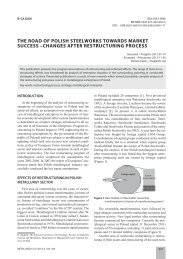
particular phases can be assessed. The quickly cooled<br />
slags (Aq, Bq) show higher amount of β-C 2 S than slags<br />
As, Bs, which contain predominantly β-C 2 S (Figure 1).<br />
As<br />
Aq<br />
2<br />
1<br />
2<br />
2<br />
1<br />
2<br />
2<br />
2<br />
1<br />
1<br />
2<br />
1<br />
1<br />
1<br />
1<br />
1<br />
13 20 30 40 50 60 70 80<br />
1<br />
2-Theta - Scale<br />
2<br />
1<br />
1<br />
2<br />
1<br />
2<br />
2<br />
1<br />
1<br />
1<br />
Figure 1 XRD pattern of slags Aq and As; 1- β-C 2 S, 2 - γ-C 2 S<br />
The β-C 2 S content is also important due to its direct<br />
hydraulicity. Slag with suffi cient content of this phase<br />
can be used for preparation of alternative binder systems.<br />
The C 2 S phase is also important due to monitoring<br />
of volume stability of ladle slags. Transformation of<br />
β-C 2 S → γ-C 2 S running during cooling of slags is one of<br />
the causes of ladle slag disintegration. Change of modifi<br />
cation is connected with change of density within 3,29<br />
→ 2,97 Mg.m -3 . Under balanced conditions of the cooling<br />
the β-C 2 S is stabile in thermal interval from 680 -<br />
630 to 500 °C. At temperature lower than 500 °C the<br />
β-C 2 S is stable. If the slag is cooled quickly, the transformation<br />
does not occur [8, 9].<br />
b-C2S<br />
CaF2<br />
g-C2S<br />
b-C2S<br />
b-C2S<br />
b-C2S<br />
g-C2S<br />
b-C2S<br />
b-C2S<br />
b-C2S<br />
31 32 33 34 35 36 37 38 39 40 41 42 43 44 45 46 47 48 49 50 51<br />
g-C2S<br />
2-Theta - Scale<br />
Bs fine dust share<br />
Bs graind share<br />
Figure 2 Representation of β-C 2 S a β-C 2 S in piece and dust<br />
slags<br />
b-C2S<br />
1<br />
b-C2S<br />
1<br />
MgO<br />
Samples of quickly cooled slags were characterised<br />
with presence of bigger aggregates of β-C 2 S compared<br />
to slowly cooled slags that disintegrated in dust share.<br />
As an example the comparison of diffraction patterns of<br />
fi ne dust portion and coarse-grained portion are shown<br />
in Figure 2. The shares were separated from the slag Bs.<br />
The differences in phase composition are demonstrated<br />
by higher intensities of diffractions γ-C 2 S in the fi ne<br />
dust share and on the contrary the β-C 2 S shows higher<br />
intensities in case of coarse grained share.<br />
Other reason for volume instability is the presence<br />
of free CaO and/or MgO. By hydration of these components<br />
relevant hydroxides are formed which are able of<br />
further carbonisation, more detail can be found in the<br />
work [1], [9].<br />
The presented slags mostly show crystalline character.<br />
Quick cooling of melted slags was performed with<br />
aim to ensure its amorphous glass character. This was<br />
successful only in case of two ladle slag samples. The<br />
slag Fq includes a high share of glass forming SiO 2<br />
(38 wt%) and basicity is 1,0. Other sample with amorphous<br />
structure is the slag Cq, where content of SiO 2<br />
(24 wt%) is lower in comparison with the slag Fq, but<br />
also contains a lower share of alkaline components, the<br />
basicity reaches the value 1,4.<br />
Legenda: (FeO)x(MnO)y ... (FeO)0.798(MnO)0.202<br />
(MgO)x(FeO)y ... (MgO)0.77(FeO)0.23<br />
M ... Ca3Mg(SiO4)2 (Merwinit)<br />
G ... Ca2Al2SiO7 (Gelenit)<br />
P ... MgO (periklas)<br />
Mixture of Cq and Cs<br />
5 10 20 30 40 50 60 70 80<br />
2-Theta - Scale<br />
332 METALURGIJA 52 (2013) 3, 329-333<br />
Cq<br />
G<br />
G<br />
G<br />
G<br />
G<br />
M<br />
M<br />
M<br />
(MgO)x(FeO)y<br />
G<br />
G<br />
P<br />
M G<br />
(FeO)x(MnO)y<br />
(MgO)x(FeO)y<br />
P<br />
M<br />
G<br />
M<br />
G<br />
M<br />
G<br />
G<br />
(FeO)x(MnO)y<br />
(MgO)x(FeO)y<br />
Figure 3 XRD pattern of slags Cq and mixture of Cq and Cs<br />
The fact the x-ray diffraction with other slags did not<br />
mean presence of glassy phase does not exclude its factual<br />
presence. The diffraction pattern on Figure 3 is the<br />
proof. The X-ray record of mixture of slags Cq and Cs<br />
(60:40 wt%) did not noticed content of glass while the<br />
record of glassy phase has typical XRD course for<br />
amorphous materials.<br />
From the Table 2 it is also obvious that industrial<br />
slag processing within the metallurgical factory forms<br />
its phase composition differently from composition of<br />
slags taken from melting units. While the slag Fq taken<br />
from the casting ladle shows amorphous structure, the<br />
same slag taken from different nodal points of its further<br />
processing (samples Fsa, Fsb and Fsc) shows crystalline<br />
character. Cooling speed that in industrial conditions<br />
in respect of slag volume (approximately 10 tons)<br />
took place notably more slowly than in case of incomparably<br />
smaller laboratory sample (approx. 5 kg) is the<br />
reason. At the same time the phase composition of the<br />
P
METALURGIJA 52 (2013) 3, 329-333<br />
J. VLCEK et al.: <strong>SLAGS</strong> <strong>FROM</strong> <strong>STEEL</strong> <strong>PRODUCTION</strong>: <strong>PROPERTIES</strong> <strong>AND</strong> <strong>THEIR</strong> UTILIZATION<br />
slag in various processing nodal points is unchanged as<br />
assumed.<br />
CONCLUSIONS<br />
Origination of the slags during the steel production<br />
is inevitable and cannot be prevented. Utilisation of the<br />
slags is limited by its chemical and phase composition.<br />
In case of slag recycling in melting plants for steel production<br />
the present iron is being used and eventually<br />
other components CaO, MgO and Al 2 O 3 as well. In the<br />
mentioned case the chemical composition of the slags is<br />
decisive. On the contrary the phase composition of slags<br />
is decisive at its processing for aggregates or at utilisation<br />
of slag binder properties.<br />
To fi nd an optimal way for utilisation of steel slags it<br />
is necessary to monitor parameters of the slags during<br />
its processing. Owing to processes to which the slag is<br />
exposed to in this phase, its chemical and phase composition<br />
may change what is essential fact for slag utilisation.<br />
Acknowledgements<br />
Financial support of the Technology Agency CR<br />
(project reg. No. TA02020777 “Research and develop-<br />
ment of methods for environmental friendly recycling<br />
of secondary raw materials”) are gratefully acknowledged.<br />
The study was also supported by Ministry of<br />
Education, Youth and Sports of the Czech Republic<br />
(project reg. No. SP2012/28 ).<br />
REFERENCES<br />
[1] J. Vlcek, et al. METAL 2012 Conference proceedings,<br />
Brno, 2012, pp. 195 -201<br />
[2] J. Vlcek, V. Tomková, et al. Metalurgija, 48, (2009), 4,<br />
223-227.<br />
[3] V. Václavík, et al. Metalurgija 51 (2012) 4, 461-464C.<br />
[4] Shi, et. al. Alkali-Activated Cement and Concretes, Taylor<br />
& Francis, London, 2006, pp.45-48.<br />
[5] D. Baricova, et al. Metalurgija 51 (2012) 4, 465-468.<br />
[6] L. Svoboda, et al., Stavební hmoty, JAGA GROUP, Bratislava,<br />
2007, pp. 100 – 108.<br />
[7] J. Vlcek, et al. Strusky z výroby železa a oceli a jejich objemová<br />
stabilita. Stavební obzor, 2012, 5, pp. 177-187.<br />
[8] G. C. Bye Portland cement, Thomas Telford Publishing,<br />
London, 1999, pp. 11-13.<br />
[9] W. Kurdowski, Chemia cementu i betonu, SPC, Krakow,<br />
2010, pp. 103-107.<br />
Note: The responsible translator for English language is the lectures<br />
from TU Ostrava, Czech Republic<br />
333