Metalurgija: sadašnjost Metallurgy: Present Metalurgija ... - CARNet
Metalurgija: sadašnjost Metallurgy: Present Metalurgija ... - CARNet
Metalurgija: sadašnjost Metallurgy: Present Metalurgija ... - CARNet

You also want an ePaper? Increase the reach of your titles
YUMPU automatically turns print PDFs into web optimized ePapers that Google loves.
METALURGIJA – ČASOPIS OSNOVAN 1962.<br />
OSNIVAČ – DRUŠTVO INŽENJERA I TEHNIČARA ŽELJEZARE SISAK<br />
METALURGIJA – JOURNAL FOUNDED IN 1962<br />
FOUNDER – SOCIETY OF ENGINEERS AND TECHNITIANS OF STEELWORKS SISAK<br />
UDK 669+621.7 + 51/54 (05) = 163.42 = 111<br />
<strong>Metalurgija</strong>: prošlost XVI. st.<br />
<strong>Metallurgy</strong>: Past - XVI. cent.<br />
ISSN 0543-5846<br />
METABK 52 (1) 1-144 (2013)<br />
1<br />
52 nd<br />
<strong>Metalurgija</strong>: <strong>sadašnjost</strong><br />
<strong>Metallurgy</strong>: <strong>Present</strong><br />
52<br />
year<br />
METALURGIJA, vol. 52, Br./No 1, Str./P 1-144 Zagreb, Siječanj-Ožujak / January-March 2013
UDK 669+621.7+51/54(05)=163.42=111 ISSN 0543-5846<br />
METABK 52 (1) 1-144 (2013)<br />
METALURGIJA, vol. 52, Br./No 1, Str./P 1-144 Zagreb, Sije~anj-O`ujak / January-March 2013<br />
Izdava~ / Publisher: Hrvatsko metalur{ko dru{tvo (HMD) - Croatian Metallurgical Society (CMS)<br />
Adresa / Address: Berislavi}eva 6, 10 000 Zagreb, Hrvatska / Croatia<br />
Phone/Fax: + 385 1 619 86 89 (service), Mob: + 385 98 317 173<br />
Internet / On line: http://public.carnet.hr/metalurg; http://hrcak.srce.hr; http://www.doaj.org; http://search.ebscohost.com;<br />
www.socolar.com / www.cepiec.com.cn; (On line) ISSN 1334-2576, (CD-ROM) ISSN 1334-2584<br />
Uredni~ki odbor / Editorial Board:<br />
F. VODOPIVEC - zamjenik glavnog i odgovornog urednika / Deputy of Editor-in-Chief, Ljubljana - Slovenia, I. JURAGA,<br />
Zagreb - Croatia, I. ALFIREVI], Zagreb - Croatia, S. DOBATKIN, Moscow - Russia, L. BLACHA, Katowice, Poland,<br />
H. HIEBLER, Leoben - Austria, M. HOLTZER, Krakow - Poland, I. SAMARD@I], Slavonski Brod - Croatia, R. KAWALLA,<br />
Freiberg - Germany, I. MAMUZI], Zagreb - Croatia, L. MIHOK, Ko{ice - Slovakia, J. KLIBER, Ostrava - Czech, A. VELI^KO,<br />
Dnipropetrovsk - Ukraine, B. KOSEC, Ljubljana - Slovenia<br />
Glavni i odgovorni urednik / Editor-in-chief: ILIJA MAMUZI], ilija.mamuzic@public.carnet.hr<br />
Lektori / Linguistic Advisers: B. ZELI], hrvatski jezik/Croatian language, V. MI[URA, engleski jezik / English language<br />
Urednik i Internet/ Editor and on line: B. MACAN, bmacan@irb.hr,<br />
UDK / UDC: LJ. VUKOVI]<br />
METALURGIJA izlazi u ~etiri broja godi{nje. Godi{nja pretplata 53 EUR (protuvrijednost u kunama).<br />
METALLURGY is published quarterly. Subscription rates per year 53 EUR.<br />
Komp. obrada / Comp. design; Tisak / Print: Denona d.o.o., Zagreb, e-mail:denona@denona.hr<br />
Naklada / Print: 400 primjeraka / pieces. Rukopise ne vra}amo. / Manuscript are not returned.<br />
^asopisu “<strong>Metalurgija</strong>” daje jedino nov~anu potporu (cca. 11 000 Eur/god.)<br />
Ministarstvo znanosti, obrazovanja i {porta Republike Hrvatske.<br />
Journal “<strong>Metallurgy</strong>” is only financially supported by (cca. 11 000 Eur/y)<br />
Ministry of Science, Education and Sports Republic of Croatia.<br />
Ukupni tro{kovi / The sum total – the cost 100 000 Eur/y<br />
^lanci objavljeni u ~asopisu “<strong>Metalurgija</strong>” referiraju se u me|unarodnim sekundarnim publikacijama i bazama podataka.<br />
Articles published in the journal “METALLURGY” are indexed in the international secundary periodicals and databases:<br />
- ISI web of Science<br />
- Science Citation Index (Expanded)<br />
- Materials Science Citation Index (MSCI)<br />
- EBSCOhost Academic Search Complete<br />
- Research Alert (ISI)<br />
- Metals Abstracts<br />
- EI Compendex Plus<br />
- CA Search (R)<br />
- PaperChem<br />
- Metadex<br />
- Geobase<br />
- Chemical Abstracts<br />
- Mechanical Engineering Abstracts<br />
- Aluminium Industry Abstracts<br />
- Dialog Sourceone (SM) Engineering<br />
Note: Authors themselves are liable for the content of the paper.<br />
- Energy Science Technology<br />
- Engineered Materials Abstracts<br />
- Analytical Abstracts Online<br />
- Chemical Engineering and Biotechnology Abstracts<br />
- Referativny Zhurnal<br />
- Fluidex<br />
- Embase<br />
- Elsevier Biobase<br />
- Elsevier Geo Abstracts<br />
- Corrosion Abstracts<br />
- World Texstiles<br />
- Scopus<br />
- EMBiology<br />
- TEME<br />
- etc.
METALURGIJA 52 (2013) 1, 1-3<br />
Content – Sadržaj<br />
I. Mamuzić<br />
FIRST CIRCULAR – CALL FOR PAPERS / SHMD ’2014<br />
11 th International Symposium of Croatian Metallurgical Society<br />
PRVO PRIOPĆENJE – POZIV ZA REFERATE<br />
11. međunarodni smpozij Hrvatskog metalurškog društva 5<br />
I. Mamuzić<br />
Zapisnik sa sastanka Uredničkog odbora časopisa <strong>Metalurgija</strong><br />
Minutes of the meeting of the Editorial Board of the Journal <strong>Metalurgija</strong> 9<br />
Original Scientifi c Papers – Izvorni znanstveni radovi<br />
A. Nagode, G. Klančnik, M. Bizjak, D. Kovačević, B. Kosec, E. Dervarič, B. Zorc, L. Kosec<br />
Structural and thermodynamic analysis of whiskers on the surface of grey cast iron 11<br />
P. Malatyńska, J. Głownia<br />
Carbon content infl uence on the peritectic reaction path in stainless steels 15<br />
K. Kocúrová, M. Dománková, M. Hazlinger<br />
The infl uence of carbonitriding process on microstructure and mechanical properties<br />
of micro-alloyed steel 19<br />
A. Kawałek, J. Rapalska-Nowakowska, H. Dyja, B. Koczurkiewicz<br />
Physical and numerical modelling of heat treatment the precipitation-hardening<br />
complex-phase steel (CP) 23<br />
M. Burzić, M. Manjgo, D. Kozak, R. Prokić-Cvetković, O. Popović<br />
The effects of dynamic load on behaviour of welded joint A-387 Gr. 11 alloyed steel 27<br />
S. Wiewiórowska, Z. Muskalski<br />
Analysis the infl uence of drawing process parameters on the amount of retained<br />
austenite in trip steel wires 32<br />
H. Dyja, K. Sobczak, A. Kawałek, M. Knapiński<br />
The analysis of the infl uence of varying types of shape grooves on the behaviour<br />
of internal material discontinuities during rolling 35<br />
K. Laber, S. Mróz, P. Sygut, H. Dyja<br />
Analysis of the temperature change over the continuous ingot length on the parameters<br />
of round bar rolling process 39<br />
M. Suliga, R. Kruzel<br />
The mechanical properties of high carbon steel wires drawn in conventional<br />
and hydrodynamic dies 43<br />
Preliminary Notes – Prethodna priopćenja<br />
B. Grabowska, M. Holtzer, R. Dańko, M. Górny, A. Bobrowski, E. Olejnik<br />
New BioCo binders containing biopolymers for foundry industry 47<br />
A. Pribulová, P. Futaš, A. Rosová, P. Demeter, D. Baricová<br />
Infl uence of foundry dust on moulding mixtures quality 51<br />
J. Kolczyk, J. Zych<br />
Rheological properties of ceramic slurries with colloidal binders used in<br />
the investment casting technology 55<br />
1
J. Kamińska, J. Dańko<br />
Granulation process of foundry dusts originated from bentonite sand processing plants 59<br />
D. Kwaśniewska-Królikowska, M. Holtzer<br />
Selection criteria of lustrous carbon carriers in the aspect of properties of greensand system 62<br />
T. Bončina<br />
Shapes of the icosahedral quasicrystalline phase in melt-spun ribbons 65<br />
J. Łabaj, M. Słowikowski, W. Żymła, J. Lipart<br />
Possible ways of refi ning precious group metals (PGM) obtained from recycling<br />
of the used auto catalytic converters 68<br />
K. Janiszewski<br />
Industrial application of liquid steel fi ltration out of dispersed nonmetallic phase<br />
in the continuous casting machine 71<br />
B. Kalandyk, M. Starowicz, M. Kawalec, R. Zapała<br />
Infl uence of the cooling rate on the corrosion resistance of duplex cast steel 75<br />
T. Frączek, M. Olejnik<br />
A model for unconventional glow discharge nitriding of grade 2 titanium 79<br />
Gh. Amza, D. Dobrotă<br />
Ultrasound effect on the mechanical properties of parts loaded by welding 83<br />
D. Dobrotă, Gh. Amza<br />
Ultrasound infl uence on materials structure in parts reconditioned by<br />
welding with ultrasonic fi eld 87<br />
Gh. Amza, D. Dobrotă<br />
Researches concerning the ultasonic energy infl uence on the resistence<br />
to the abrasive wear of loaded welded parts 90<br />
R. Kruzel, M. Suliga<br />
The effect of multiple bending of wire on the residual stresses of high carbon steel wires 93<br />
Z. Muskalski, S. Wiewiórowska, M. Pełka<br />
The infl uence of drawing parameters on the properties high-manganese TWIP steel wires 96<br />
B. Grizelj, J. Cumin, D. Grizelj<br />
Effect of spring-back in v-tool bending of high-strength steel sheet metal plates 99<br />
Z. Pater, A. Tofi l, J. Tomczak<br />
Steel balls forming by cross rolling with upsetting 103<br />
B. Oleksiak, G. Siwiec, A. Blacha-Grzechnik<br />
Recovery of precious metals from waste materials by the method of fl otation process 107<br />
A. Čikić, A. Pintarić, I. Samardžić<br />
The infl uence of biomass quality on the purifi cation of fl ue gases and multicyclone<br />
assembly material 111<br />
D. Letić, B. Davidović, I. Berković, B. Radulović, J. Savičić<br />
Planning of designing and installation of mechanical elements at the gear speed reducer<br />
on the basis of the parameter technology 115<br />
J. Šebo, J. Buša, P. Demeč, J. Svetlík<br />
Optimal replacement time estimation for machines and equipment based on cost function 119<br />
2 METALURGIJA 52 (2013) 1, 1-3
METALURGIJA 52 (2013) 1, 1-3<br />
Review Papers – Pregledni radovi<br />
A. Wziątek-Staśko<br />
Diversity management – a tool to improve a metallurgic enterprise 123<br />
W. Sroka<br />
Coopetition in the steel industry − analysis of coopetition relations in the value net 127<br />
Professional Papers – Strukovni radovi<br />
B. Gajdzik<br />
World class manufacturing in metallurgical enterprise 131<br />
J. Kutáč, K. Janovská, A. Samolejová, P. Besta, Š. Vilamová I. Vozňáková<br />
The impact of production capacity utilization on metallurgical companies fi nancing 135<br />
B. Gajdzik<br />
Diagnosis of employee engagement in metallurgical enterprise 139<br />
Croatian Metallurgical Society<br />
Godišnja skupština Hrvatskog metalurškog društva (HMD)<br />
Annual Assambly of Croatian Metallurgical Society (CMS) 4<br />
I. Mamuzić<br />
Zahvala recenzentima 51(2012 god.)<br />
Acknowledgement to Reviewers 51(2012) 138<br />
I. Mamuzić<br />
Survey of 10th International Symposium of Croatian Metallurgical Society (CMS)<br />
SHMD `2012 143<br />
3
Godišnja skupština Hrvatskog metalurškog<br />
društva (HMD)<br />
Annual Assambly of Croatian Metallurgical<br />
Society (CMS)<br />
Šibenik, Solaris Beach Resort, 2012-06-19, Dvorana Prvić / Hall Prvić, 6-8 PM<br />
Usvaja se / Has adopted:<br />
1. Izvješće o djelatnosti Hrvatskog metalurškog društva (s osvrtom na međunarodne<br />
aktivnosti) za 2011. god. / The Report on the activities of the Croatian<br />
Metallurgical Society in 2011(including international activities)<br />
2. Račun Prihoda i Rashoda za 2011. god.; Bilanca na dan 31. prosinca 2011.<br />
god.; Bilješka uz fi nancijsko izvješće za 2011. god. / Income & expenditure<br />
account 2011; Balance Sheet as at 31 December 2011; Notes to the - Financial<br />
Report 2011<br />
3. Program djelatnosti Hrvatskog metalurškog društva u 2012. god. (posebice<br />
planirane međunarodne aktivnosti) / Action Programme of the Croatian Metallurgical<br />
Society for 2012 (with special reference to the planned international<br />
activities)<br />
4. Proračun za 2012. god. (posebice za međunarodne aktivnosti) / 2012 Budget<br />
(with special reference to the planned international activities)<br />
5. Iznos godišnje članarine u 2012. god. za pravne i pojedinačne osobe / Membership<br />
fees in 2012 for legal entities and individual persons<br />
6. U Upravni odbor uključen Bojan Macan, prof., kao pojedinačna osoba / Professor<br />
Bojan Macan co-opted into the Managing Board, at the individual<br />
person (bilo nepopunjeno / was vacancy)<br />
Zastupnici iz Hrvatske, Slovenije, Slovačke,<br />
Češke, Poljske, Crne Gore (gost) / Delegates<br />
from Croatia, Slovenia, Slovakia, Czech<br />
Republic, Poland, Montenegro (guest)<br />
4 METALURGIJA 52 (2013) 1, 4
I. Mamuzić / President<br />
ORGANIZINING COMMITTEE<br />
Ten International Symposium have been held so far:<br />
1 st: Zagreb – 1994 – February, 16 – 18 (88 lectures)<br />
2 nd: Split – 1996 – June, 20 – 22 (150 lectures)<br />
3 rd: Šibenik – 1998 – June, 25 – 27 (192 lectures)<br />
4 th: Opatija – 2000 – June, 25 – 29 (333 lectures)<br />
5 th Šibenik – 2002 – June, 23 – 27 (375 lectures)<br />
6 th: Šibenik – 2004 – June, 20 – 24 (368 lectures)<br />
7 th: Šibenik – 2006 – June, 18 – 22 (475 lectures)<br />
8 th: Šibenik – 2008 – June, 22 – 26 (615 lectures)<br />
9 th Šibenik – 2010 – June 20 – 24 (541 lectures)<br />
10 th Šibenuk: 2012 – June, 17- 21 (641 lectures)<br />
THE AIM OF SYMPOSIUM `2014<br />
The aim of this Symposium is to point out all the possibilities<br />
of the materials and achievements in metallurgy.<br />
TOPICS OF THE SYMPOSIUM ARE:<br />
Materials<br />
- New Materials<br />
- Refractory Materials<br />
- The Development<br />
- Applications<br />
- Physical <strong>Metallurgy</strong><br />
METALURGIJA 52 (2013) 1, 5-8<br />
FIRST CIRCULAR – CALL FOR PAPERS<br />
Prvo priopćenje – poziv za referate<br />
11 th International Symposium of Croatian Metallurgical Society<br />
11. međunarodni simpozij Hrvatskog metalurškog društva<br />
»Materials and <strong>Metallurgy</strong>«<br />
»Materijali i metalurgija«<br />
http://public.carnet.hr/metalurg<br />
SHMD `2014<br />
Šibenik 2014, June 22 – 26, Solaris Beach Resort , Croatia<br />
(Based on the Agreement of Meeting of world Metallurgical Societies, Dusseldorf 2010)<br />
11 th International Symposium of Croatian Metallurgical Society<br />
»Materials and <strong>Metallurgy</strong>« will be held as part of:<br />
95 th anniversary of the Foundation of the Technical Faculties University of Zagreb<br />
(1919 – 2014), Croatia<br />
95 th anniversary of the Foundation of Dnepropetrovsk National University<br />
(1919 – 2014), Ukraine<br />
75 th anniversary of Studies of <strong>Metallurgy</strong> University of Ljubljana<br />
(1939 – 2014), Slovenia<br />
60 th anniversary of the Establishment of Institute of Materials Research,<br />
Slovak Academie of Sciences (1950 – 2014)<br />
<strong>Metallurgy</strong><br />
- Process <strong>Metallurgy</strong> and Foundry<br />
- Plastic Processing of Metals and Alloys<br />
- Technologies<br />
- Energetics<br />
- Ecology in <strong>Metallurgy</strong><br />
- Quality Assurance and Quality Menagement<br />
Here are the most important details on the 10 th Symposium<br />
of Croatian Metallurgical Society<br />
ORGANIZER CROATIAN METALLURGICAL SOCIETY<br />
(CMS)<br />
PATRONS<br />
– European Steel Institute Confederation (ESIC)<br />
– European Steel Federation (ESF)<br />
– World Steel Association (WSA)<br />
– Ministry of Science, Education and Sport Republic of<br />
Croatia<br />
– Croatian Chamber of Economy<br />
– Sisak – Moslavina County<br />
– University of Osijek, Faculty of Mechanical Engineering,<br />
Slavonski Brod, Croatia<br />
– Technical University of Košice, Košice, Slovakia<br />
5
I. MAMUZIĆ: SHMD `2014<br />
CO-ORGANIZERS<br />
– Academy of Engineering Science of Ukraine<br />
– University of Mining and <strong>Metallurgy</strong>, Faculty of<br />
Foundry Engineering, Krakow<br />
– University of Ljubljana, Faculty of Natural Science<br />
and Engineering<br />
– Baikov Institute of <strong>Metallurgy</strong> and Materials Science<br />
Russian Academy of Sciences, Moscow<br />
– University of Zenica, Faculty for <strong>Metallurgy</strong> and Materials<br />
Science, Zenica<br />
– National Metallurgical Academy of Ukraine<br />
– Technical University of Košice, Faculty of <strong>Metallurgy</strong><br />
– Technical University of Košice, Faculty of Mechanical<br />
Engineering<br />
– Technical University of Košice, Berg Faculty<br />
– University of Zagreb, Faculty of Mechanical Engineering<br />
and Naval Architecture<br />
– University of Osijek, Faculty of Mechanical Engineering,<br />
Slavonski Brod<br />
– VŠB Technical University of Ostrava<br />
– Institute of Materials Research of the Slovak Academy<br />
of Sciences in Košice<br />
– Moscow State Steel and Alloys Institute<br />
– Physico-Technical Institute National Academie of<br />
Science, Minsk<br />
– Politehnica University of Bucharest<br />
– Institute of <strong>Metallurgy</strong> “Kemal Kapetanović”, Zenica<br />
– Pisarenko Institute of Problems of Strenght NASU,<br />
Kiev<br />
– Dnepropetrovsk National University<br />
– Czech Steel Federation<br />
– Slovak University of Technology in Bratislava, Faculty<br />
of Materials Science and Technology<br />
– Vatrostalna Sisak d.o.o.<br />
– High Technical School - Bjelovar<br />
– University of Applied Sciences, Slavonski Brod<br />
– University of Applied Sciences, Vukovar<br />
– University of Applied Sciences, Varaždin<br />
– Institute of Metals and Technology, Ljubljana<br />
– Czestochowa University of Technology<br />
– Silesian University of Technology, Katowice<br />
– Branch of Slovak Metallurgical Society, Seat in TU<br />
Košice<br />
CO-OPERATION WITH ORGANIZATIONS<br />
– Stahlinstitut VDEh, Germany<br />
– ATS - Association Technique de la Siderurgie Francaise<br />
– CENIM - Centro National de Investigaciones Metalurgicas<br />
Spain<br />
– ChSM - The Chinese Society for Metals China<br />
– CRM - Centre de Recherches Metallurgiques Belgium<br />
– ASMET - The Austrian Society for <strong>Metallurgy</strong> and<br />
Materials<br />
– American Iron and Steel Institute, USA<br />
– ISIJ - The Iron and Steel Institute of Japan<br />
– JERN - Jernkontoret, Sweden<br />
– SRM Romanian Society for <strong>Metallurgy</strong><br />
– SITPH - Association of Polish Metallurgical Engineers<br />
– HOOGOVENS, The Netherlands<br />
– SHS - Slovak Metallurgical Society<br />
– Sociedade Portuguesa de Materiais<br />
– MVAE - Association of Hungarian Steel Industry<br />
– Steel Federation of the Czech Republic<br />
– Union of Bulgarian Metallurgists<br />
– IBS - Instituto Brasileiro de Siderugia<br />
– AIM - Associazione Italiana di Metallurgia<br />
– The Japan Institute of Metals<br />
– Egyptian Association for Industrial Development<br />
– Institute Argentino de Siderurgia<br />
– Associacao Brasileira de Metalurgia e Materiais<br />
– ILAFA - Instituto Latinoamericano del fi erroy el Acero,<br />
Chile<br />
– Société Francaise de Métallurgie et de Materiaux<br />
– The Institut of Materials, Minerals and Mining, England<br />
– P. T. Krakatau Steel, Indonesia<br />
– KOSA - Korea Iron and Steel Association<br />
– Amsteel Mills Sdn Bhd, Malaysia<br />
– Philippine Iron & Steel Institute<br />
– NatSteel Asia (S) Pte Ltd, Singapur<br />
– The South African Institute of Mining and <strong>Metallurgy</strong><br />
– Iron and Steel Institute of Thailand<br />
– Vietnam Steel Corporation<br />
SCIENTIFIC COMMITEE<br />
I. Alfi rević, Croatia<br />
L. Blacha, Poland<br />
C.Kolmasiak, Poland<br />
H. Jäger, Austria<br />
I. Juraga, Croatia<br />
R. Kawalla, Germany<br />
O. Kochubey, Ukraine<br />
L. Kosec, Slovenia<br />
I. Mamuzić, Croatia – President<br />
S. Nikulin, Russia<br />
I. Samardžić, Croatia<br />
P. Ševc, Slovakia<br />
A. Veličko, Ukraine<br />
F. Vodopivec, Slovenia – Vice President<br />
G. Weiss, Slovakia<br />
HONOUR BOARD<br />
D. Aliev, Bulgaria<br />
A. Barcelo, Spain<br />
F. Bassani, Italy<br />
S. Bockus, Lithuania<br />
F.Bujang, Indonesia<br />
J. Butterfi ld, England<br />
I. Christmas, Belgium<br />
Z. Crnečki, Croatia<br />
B. Creton, France<br />
A. Čikić, Croatia<br />
A. Čižmar, Slovakia<br />
B. Daenulhay, Indonesia<br />
P. Dahlmann, Germany<br />
V. Dančenko, Ukraine<br />
F. Egerton, S. Africa<br />
P. Fajfar, Slovenia<br />
H. L. Filho, Brazil<br />
O. Gardella, Argentina<br />
M. Godec, Slovenia<br />
J. C. Herman, Benelux<br />
P. Hornak, Slovakia<br />
H. Hiebler, Austria<br />
L. Kavanagh, USA<br />
H. J. Kerkoff, Germany<br />
S. Kim, Korea<br />
A. Kojima, Japan<br />
D. Kozak, Croatia<br />
J. Labaj, Poland<br />
M. Lovrić Merzel, Croatia<br />
H. B. Lungen, Germany<br />
G. Merczis, Hungary<br />
6 METALURGIJA 52 (2013) 1, 5-8
S. Marwah, India<br />
A. Milković, Croatia<br />
G. Moreno, Chile<br />
TV. Narendran, Singapur<br />
R. Nascimento, Brasil<br />
J. Nel, South Africa<br />
W. Nicodemi, Italia<br />
M. Oruč, B and H<br />
L. H. Osterholm, Sweden<br />
G. Parvu, Romania<br />
J. Pindor, Czech Republic<br />
Ju. Projdak, Ukraine<br />
I. Pučko, Croatia<br />
J. Raab, Czech Republic<br />
E. Raczka, Poland<br />
P. Raus, Croatia<br />
M. Saariaha, Finland<br />
O. Santiago, Spain<br />
A. Sharkey, USA<br />
A. Stoić, Croatia<br />
D. H. Tam,Vietnam<br />
P. Tardy, Hungaria<br />
J. Tušek, Slovenia<br />
G. Uzelac, Croatia<br />
W. Vajarakupta, Thailand<br />
F. A. Zaghla, Egypt<br />
Z. Zhong, China<br />
T. Wellington, Philippines<br />
ORGANIZING COMMITTEE<br />
M. Buršak, Slovakia-Vice President<br />
V. Bukhanovski, Ukraine<br />
D. Constantinescu, Romania<br />
S. Dobatkin, Russia<br />
A. Gordienko, Belarus<br />
M. Holtzer, Poland<br />
I. Kladarić,Croatia<br />
J. Kliber, Czech Republic<br />
B. Kosec, Slovenia<br />
I. Mamuzić, Croatia-President<br />
M. Math, Croatia<br />
B. Oleksiak, Poland<br />
M. Rimac, B and H<br />
T. Vlasova, Ukraine<br />
M. Warzecha, Poland<br />
GENERAL INFORMATION<br />
Languages<br />
Criatian, English (no simultaneous translation)<br />
Summarye (Abstract)<br />
All participants who intend to present a lecture are required<br />
about a Summary of Paper lecture in the following<br />
from:<br />
Initial of Name, Surname, Institution, Stat, Title of<br />
Abstract, Content – max 120 words.<br />
The workshop of Symposium will be held in plenary<br />
session<br />
(invited lectures)and posters sections.<br />
Summaries of all accepted lectures will be published in<br />
Summaries of Lectures, after paid the Participation<br />
Fee, in the Journal <strong>Metalurgija</strong> 53 (2014) 3. Invited (plenary)<br />
Papers will be also published in the Journal <strong>Metalurgija</strong><br />
53 (2014) 3, in order of acception after regular<br />
procedure. The selected Papers will be also published in<br />
the Journal <strong>Metallurgy</strong> after Symposium also with paid<br />
the Participation Fee, and accepted from the Reviewers.<br />
METALURGIJA 52 (2013) 1, 5-8<br />
I. MAMUZIĆ: SHMD `2014<br />
All correspondence and Papers send on CD to:<br />
Croatian Metallurgical Society (CMS)<br />
Berislavićeva 6, 10 000 Zagreb, Croatia<br />
Phone / Fax: +385 1 619 86 89 (service)<br />
Mob: +385 98 317 173<br />
E-mail Summaries only to:<br />
denona@denona.hr or send them on CD to CMS.<br />
DEADLINES (please see WEB site for all information<br />
– http://public.carnet.hr/metalurg)<br />
Registration and Summary: 31 st January 2014<br />
Second Circular: 31 st March 2014<br />
Programme: 31 st May 2014<br />
Papers: at latest 31 st December 2014<br />
PARTICIPATION FEE<br />
a) Participation (each the Abstract), publication of Summaries<br />
in <strong>Metallurgy</strong> issue 53 (2014) 3, presentation<br />
in the poster section …. 150 Eur<br />
b) Publication of a whole paper in Journal <strong>Metallurgy</strong><br />
(The papers not consistently prepared according to the<br />
»Instructions to Authors«, for Journal of <strong>Metalurgija</strong><br />
will not be considered – see WEB site): 450 Eur (150<br />
Eur + 300 Eur)<br />
c) Other participants and co-authors….. 100 Eur<br />
All this prices generally included symposium attendance,<br />
welcome coctail and symposium materials.<br />
Please pay Participatin Fee by 31 st January,<br />
2014 to:<br />
Croatian Metallurgical Society, Zagreb<br />
Berislavićeva 6, Croatia, the bank account No:<br />
Privredna Banka Zagreb, Croatia<br />
703000-304713<br />
IBAN: HR 76 2340 0091 1100 4804 3<br />
SWIFT CODE (BIC): PBZGHR2X<br />
For the participants from Croatia (in Croatian Kuna):<br />
2340009-1110048043<br />
Without the payement we will not publish of Abstracts<br />
or Articles.<br />
The fee can also be paid at the symposium: price +10<br />
%, for Participants without lectures.<br />
Paper presentation<br />
– Plenary lectures of invited scientists will be held.<br />
– Authors are required to prepare posters (title, abstract,<br />
results, conclusion) on a 100x100 cm paper, to be paste<br />
on a board).<br />
Eventually let us point out:<br />
The reception of 11 th Symposium of Croatian Metallurgists<br />
by international associations has shown that the<br />
Symposium has become a traditional place for the gathering<br />
of the world`s experts and scientists of various profi<br />
les: metallurgists, physicists, chemists, mechanical engineers,<br />
and technicians who can and want to contribute so<br />
that metallurgy in Croatia receives the same attention a sit<br />
does in the world.<br />
7
I. MAMUZIĆ: SHMD `2014<br />
REGISTRATION FROM SHMD`2014<br />
June 22 – 26, 2014<br />
Registration Form (see web site)<br />
should be sent not<br />
Later than 31 th January 2014<br />
Croatian Metallurgical Society,<br />
Berislavićeva 6, 10000 Zagreb, Croatia,<br />
or denona@denona.hr<br />
Name:_____________________________________<br />
Titla and Profession: _________________________<br />
University or Company: ______________________<br />
Mailing Address: ____________________________<br />
Zip Code: __________________________________<br />
City: ______________________________________<br />
Country: ___________________________________<br />
Phone: ____________________________________<br />
Fax: ______________________________________<br />
E-mail: ____________________________________<br />
Attendance: with a paper [ ] ; without a paper [ ],<br />
Title of the paper: ___________________________<br />
_________________________________________<br />
_________________________________________<br />
_________________________________________<br />
Author(s) __________________________________<br />
_________________________________________<br />
_________________________________________<br />
Date: _____________________________________<br />
Signature: _________________________________<br />
ACCOMODATION<br />
Solaris Beach Resort, Šibenik, Croatia<br />
HOTEL ACCOMODATION FORM SHMD 2014<br />
(sent only directly to Solaris)<br />
Deadline of reservation: 20 th May 2014 to:<br />
Phone: + 385 22 361 008, fax: + 385 22 361 800<br />
Solaris Beach Resort, 22 000 Šibenik, Croatia<br />
prodaja@solaris.hr<br />
Name: __________________________________<br />
Phone: __________________________________<br />
Address: _________________________________<br />
Arrival Date: ________06.2014 ; Time: _______<br />
Departure Date: ______06.2014 ; Time: _______<br />
Please indicate type of room required:<br />
(price are per person / day)<br />
double 1/2 single 1/1<br />
room + breakfast 55.00 Eur [ ] 79.00 Eur [ ]<br />
half board 60.00 Eur [ ] 84.00 Eur [ ]<br />
visitor`s tax - person / day 1.00 Eur<br />
The prices validly: June 20 – 29, 2014 (9 days)<br />
Date: ____________________________________<br />
Signature: ________________________________<br />
Information: Solaris Beach Resort<br />
Phone: + 385 22 361 004<br />
Fax: + 385 22 361 800<br />
The more details about the town Šibenik and Solaris<br />
Beach Resort, please see . www.solaris.hr<br />
8 METALURGIJA 52 (2013) 1, 5-8
Glavni i odgovorni urednik – Akad. Ilija Mamuzić Editor-in-chief – Acad. Ilija Mamuzić<br />
Urednički odbor časopisa <strong>Metalurgija</strong> Editorial Board of the Journal <strong>Metalurgija</strong><br />
Sa sastanka Uredničkog odbora časopisa <strong>Metalurgija</strong>, održanog<br />
dana 18. lipnja 2012. god. u Hotelu Ivan – Solaris, Ši benik<br />
s početkom u 12,00 sati, dvorana Kornati<br />
Sastanak je otvorio glavni i odgovorni urednik Ilija Mamuzić,<br />
pozdravio nazočne, te predložio sljedeći:<br />
METALURGIJA 52 (2013) 1, 9-10<br />
DNEVNI RED<br />
1. Promocija Monografi je »<strong>Metalurgija</strong> uvijek prosperitet za<br />
čovječanstvo« sa »Bibliografi ja časopisa <strong>Metalurgija</strong><br />
1962. – 2012.« (u 12,00 sati)<br />
2. Očevid u časopisu <strong>Metalurgija</strong> i preporuke za budući rad<br />
3. Raznoliko<br />
Dnevni red je prihvaćen.<br />
Ad. 1.<br />
Glavni i odgovorni urednik je istakao, da sukladno Pravilniku<br />
časopisa <strong>Metalurgija</strong> članak 10., sastanci međunarodnog<br />
Uredničkog odbora održavaju se najmanje jedanput u dvije godine.<br />
Zadnji sastanak je održan u Šibeniku 21. lipnja 2010., a zapisnik<br />
sasastanka objavljen u Metalurgiji 49 (2010) 4, 291.-292.<br />
I. Mamuzić je također napomenuo, da na temelju Odluke<br />
Upravnog odbora Hrvatskog metalurškog društva (6. sjednica<br />
25.05.2012. god.) za promociju Monografi je »<strong>Metalurgija</strong> uvijek<br />
prosperitet za čovječanstvo« su uz autora Monografi je I. Mamuzića,<br />
predloženi:<br />
– Franc Vodopivec, kao recenzent Monografi je i član<br />
Uredničkog odbora časopisa <strong>Metalurgija</strong> od 1987. god.<br />
– Jiri Kliber član Uredničkog odbora časopisa <strong>Metalurgija</strong><br />
od 1996. god.<br />
– Ivan Samardžić zamjenik glavnog i odgovornog urednika<br />
časopisa Metalurgije i zastupnik hrvatskih znanstvenika<br />
Autor Monografi je je prvo dao izvješće po poglavljima monografi<br />
je:<br />
– 50 godina »Bibliografi ja časopisa <strong>Metalurgija</strong><br />
1962.-2012.«<br />
– 60 godina utemeljenja Hrvatskog metalurškog društva<br />
(HMD) 1952.-2012.<br />
– 9000 godina u svijetu, a 6000 metalurgije na ovim prostorima<br />
– 50 godina visokoškolske (sveučilišne) nastave u metalurgiji<br />
Hrvatske<br />
Istaknuti su ciljevi i zadaci Monografi je, te da je na jednom<br />
mjestu dat prikaz povijesti i događanja u Hrvatskoj metalurgiji<br />
tijekom 6000 godina, posebice propast 1990.-2012. god.<br />
F. Vodopivec kao recenzent dao je detaljni osvrt o značaju<br />
ove Monografi je i posebice čestitke povodom 50 godina tiska<br />
časopisa <strong>Metalurgija</strong>.<br />
J. Kliber se jednako osvrnuo na dugogodišnju suradnju i veliki<br />
doprinos ove Monografi je ne samo za Hrvatsku.<br />
I. Samardžić je istakao značaj i ulogu HMD-a, te doprinos<br />
časopisa <strong>Metalurgija</strong>, gdje objavljuju autori iz preko 30-ak<br />
država. Posebice u Bibliografi ji je očevid u Listu autora i Listu<br />
objavljenih radova tijekom 50 godina.<br />
Na kraju promocije autor je pročitao dva e-maila:<br />
ZAPISNIK / MINUTES<br />
Of the meeting of the Editorial Board of the Journal <strong>Metalurgija</strong>,<br />
held on 18 June, 2012 in the Hotel Ivan – Solaris, Šibenik<br />
with the beginning at 12 AM, Kornati Hall<br />
Nazočni / <strong>Present</strong>: I. Samardžić, S. Dobatkin, V. Balakin (zamjenik za / deputy for A. Veličko), M. Holtzer, I. Juraga, R. Kawalla, M.<br />
Buršak (zamjenik za / deputy for L.Mihok), J. Kliber, I. Mamuzić, M. Ikonić (gost / guest)<br />
Izočni / Absents: H. Hiebler, I. Alfi rević (excused), T. Mikac, Ž. Domazet (unexcused)<br />
Nazočno također / <strong>Present</strong> also: 200 osoba / Persons<br />
The Editor-in-chief, Ilija Mamuzić opened the meeting,<br />
greeting all the attendants and proposed the following:<br />
AGENDA<br />
1. Promotion of Monograph »<strong>Metallurgy</strong>, always prosperity<br />
for humanity« with »Bibliography of Journal <strong>Metalurgija</strong><br />
1962 – 2012« (at 12 AM)<br />
2. Opinions on the Journal <strong>Metalurgija</strong> and recomendations for<br />
future work<br />
3. Other Business<br />
The Agenda was accepted.<br />
Ad. 1.<br />
The Editor-in-chief pointed out that pursuant to the Rule<br />
Book of the Journal <strong>Metalurgija</strong>, Article 10, the Meetings of the<br />
International Editorial Board shall be held at least once in two<br />
years. The last meeting was held in Šibenik, Solaris, 21 June<br />
2010 and the Minutes of the meeting were published in <strong>Metalurgija</strong><br />
49 (2010) 4, 291-292.<br />
I. Mamuzić pointed out also, that on the basis of the Decision<br />
of Menagement Board of Croatian Metallurgical Society (6 th<br />
Meeting May 25, 2012) for promotion of Monograph« <strong>Metallurgy</strong>,<br />
always prosperity for humanity« are by the Author of<br />
Monograph proposed:<br />
– F. Vodopivec, as the reviewer of Monograph and Member<br />
of Editorial Board of Journal <strong>Metalurgija</strong> since 1987 y.<br />
– Jiri Kliber, Member of Editorial Board of Journal <strong>Metalurgija</strong><br />
since 1996 y.<br />
– Ivan Samardžić, deputy of Editor-in-chief of Journal <strong>Metalurgija</strong><br />
and the delegate of Croatian Scientifi sts.<br />
The Author of Monograph fi rst pointed out the report of<br />
Chapters Monograph:<br />
– Fifty years »Bibliography of Journal <strong>Metalurgija</strong> 1962-<br />
2012«.<br />
– Sixty years of the foundation of Croatian Metallurgical Society<br />
(CMS) 1952-2012.<br />
– 9000 years in the world and 6000 of the <strong>Metallurgy</strong> on the<br />
local territory.<br />
– Fifty years of high school (University level) the education<br />
in the <strong>Metallurgy</strong> of Croatia (1960-2010).<br />
The goals and tasks of the Monograph have been defi ned and<br />
then the 6,000-year history of metallurgy on the Croatian soil<br />
presented, especially including the last period of its decline<br />
(1990-2012).<br />
F. Vodopivec as a reviewer has given a detailed account of the<br />
importance of the Monograph and extended his congratulations on<br />
the occasion of the 50th anniversary of <strong>Metalurgija</strong> journal.<br />
J. Kilber has praised the longstanding cooperation and major<br />
contributions of the Monograph for Croatia and beyond.<br />
I. Samardžić has emphasised the importance and role of the<br />
Society, as well as that of <strong>Metalurgija</strong> journal where authors from<br />
9
I. MAMUZIĆ: ZAPISNIK / MINUTES<br />
a) od prvog glavnog i odgovornog urednika časopisa <strong>Metalurgija</strong><br />
(1962 – 1963. god.) Branka Mayerholda:<br />
Poštovani gospodin Ilija Mamuzić,<br />
vrlo me je obradovala« <strong>Metalurgija</strong>« i priložena Bibliografi ja.<br />
Iskrene čestitke uz sjećanja na sve dobre i drage ljude u Željezari<br />
Sisak – njih više nema, ali oni žive u našim sjećanjima i u ovoj<br />
Monografi ji 1962.-2012. A Vama posebno stežem ruku prijateljstva<br />
kao zahvalu za Vaš trud i upornost da se održi u životu<br />
časopis »<strong>Metalurgija</strong>« i spomen na metaluršku proizvodnju kroz<br />
šest hiljada godina metalurgije na našim prostorima.<br />
Vaš Branko Mayerhold<br />
b) od umirovljenog profesora Sveučilišta u Zagrebu, Josipa<br />
Krajcara sudionika događanja u hrvatskoj metalurgiji<br />
preko 30 godina, autora više tekstova i članaka u časopisu<br />
<strong>Metalurgija</strong> ili dnevnom tisku:<br />
Poštovani profesore, lijep pozdrav.<br />
Hvala vam lijepa za Vašu novu knjigu koju sam prekjučer<br />
dobio. Prijatno ste me iznenadili i jako obradovali. Divim se<br />
Vašoj aktivnosti i čestitam vam na ovom velikom poduhvatu.<br />
Knji ga mi je došla kao prava terapija u dane kada se ne osjećam<br />
baš jako ornim. S velikim sam je zanimanjem prelistao, uvjerio se<br />
da ima mnogo zanimljivih podataka koji me podsjećaju na probleme<br />
i suradnike iz prošlih vremena. Nastavit ću sa čitanjem.<br />
Želim Vam sve najbolje i lijepo Vas pozdravljam.<br />
Josip Krajcar<br />
Promocija je završila rad u 13,30; nastavak sjednice Uredničkog<br />
odbora je bio u 6,30 sa točkama 2. i 3.; izočan I. Juraga –<br />
opravdano.<br />
Ad. 2.<br />
Članovi Uredničkog odbora pohvalno su se izrazili o dosadaš<br />
njoj djelatnosti časopisa:<br />
– uključenost u tercijalne i sekundarne publikacije i baze podataka,<br />
uz ISI izdanje i preko 30-ak baza podataka<br />
– redovitost tiskanja (svaki broj se tiska nekoliko mjeseci<br />
pred termin važenja)<br />
– opremljenost časopisa, itd.<br />
– javna dostupnost – uz normalni pisani oblik izdaje se i na<br />
CD – romu, te cjelovito na pet web-stranica<br />
– IF (faktor odjeka) 0,37<br />
– veće smanjenje grešaka (u odnosu na prije / prijevoda i<br />
lekture engleskog jezika)<br />
– veliko poboljšanje kakvoće tiska časopisa izborom nove<br />
tiskare Denona, itd.<br />
Časopis <strong>Metalurgija</strong> pokriva tehnička i ostala područja pa je<br />
tako različite tekstove teško lektorirati, odnosno prevoditi (engleski,<br />
hrvatski jezik).<br />
Ad. 3.<br />
Nazočni članovi Uredničkog odbora časopisa <strong>Metalurgija</strong> su<br />
i aktivni sudionici na 10. simpoziju »Materijali i metalurgija«,<br />
Šibenik 17.-21.06.2012. Istakli su u raspravi, visoku kakvoću<br />
sim pozija gdje je prijavljeno 641 referat iz 48 država, dobru organizaciju<br />
te ugodan ambijent u hotelima Solaris.<br />
Sukladno i do sada terminima održavanja međunarodnog<br />
Ured ničkog odbora časopisa <strong>Metalurgija</strong>, te Pravilniku časopisa<br />
<strong>Metalurgija</strong> (članak 10.) slijedeći sastanak je zakazan za 23. lipnja<br />
2014. godine.<br />
Sastanak je završio u 21,00 sati.<br />
10<br />
more that 30 countries have published their works. The Bibliography<br />
of the journal (1962-2012) gives a List of authors and a<br />
List of works published over the past 50 years of the journal’s<br />
continuous publication.<br />
At the end of the promotion ceremony the author read two<br />
e-mails<br />
a) From B. Mayerhold fi rst Editor-in-chief of the Journal<br />
<strong>Metalurgija</strong> (1962 – 1963)<br />
Respected Mr. Ilija Mamuzić,<br />
I was very glad to receive the Monograph with the attached Bibliography<br />
My heartfelt congratulations with remembrances of all the good<br />
and dear people of Sisak Steelworks, many of whom are no longer<br />
with us but who live in our memories and this Monograph<br />
1962-2012. As for you in particular, I shake you hand cordially,<br />
thanking you for your dedication and endeavour to keep <strong>Metalurgija</strong><br />
journal alive, in memory to the six millennia of metallurgic<br />
manufacture in our territories<br />
Yours Branko Meyerhold<br />
b) From J. Krajcar, a retired professor of University Zagreb, who<br />
for more than 30 years participated in all major events related<br />
to the Croatian metallurgy and contributed a number of articles<br />
and texts to the Journal <strong>Metalurgija</strong> and newspapers<br />
Dear Professor, extending my warm greetings and thanks for<br />
your new book I received the day before yesterday. It has been a<br />
very nice surprise. I admire your vitality and congratulate you on<br />
this major undertaking. The book has come to me as a real therapy<br />
at a time when I m not feeling rather low. I have looked<br />
through the book with great interest and taken note of a lot of<br />
interesting information that remind me of the problems we once<br />
faced and the colleagues we worked with. I’ll surely go on reading<br />
it. I wish you all the best.<br />
Regards Josip Krajcar<br />
Promotion fi nished in 1,30 PM; the prolongation of Meeting<br />
of Editorial Board was in 6,30 PM, number 2 and 3. Absent: I.<br />
Juraga (excused).<br />
Ad. 2.<br />
Members of the Members of the Editorial Board expressed<br />
their compliments on the activity of the Journal so far:<br />
– involvement in teriary and secondary publications and databases,<br />
with ISI issue and over 30 databases<br />
– printing regularity (every issue is printed several months in<br />
advance)<br />
– the journal is well equipped. Etc.<br />
– public availability – in addition to normal hardcopy it is<br />
issued on CD-ROM, and integrally on fi ve web-site<br />
– IF (impact factor) 0,37<br />
– Substantial reduction of errors (in relation to earlier issues<br />
/ in translations and proofreading in English)<br />
– Great improvement of the journal printingquality by choosing<br />
a new printing house, Denona, etc.<br />
Journal <strong>Metalurgija</strong> covers technical as well as other areas,<br />
consequently such a broad range of different texts is diffi cult to<br />
revise, i. e. translate (English – Croatian languages).<br />
Ad. 3.<br />
The present members of the International Editorial Board of<br />
the Journal <strong>Metalurgija</strong> have also taken an active part in 10 th<br />
Symposium »Materials and <strong>Metallurgy</strong>«, Šibenik 17 – 21 June<br />
2012. In discussion, they emphasized high quality of the Symposium<br />
with 641 reports from 48 countries, good organization and<br />
comfortable atmosphere in Solaris hotels.<br />
In compliance with the terms the International Editorial<br />
Board of the Journal <strong>Metalurgija</strong> has been held so far, and the<br />
Rule Book of the Journal <strong>Metalurgija</strong> (Article 10) the next meeting<br />
is scheduled to be held on 23 June 2014.<br />
The meeting ended at 9,00 PM<br />
Promocija Monografi je, (slijeva na desno):<br />
Promotion of Monograph (from left to right):<br />
I. Mamuzić, F. Vodopivec, J. Kliber, I. Samardžić<br />
METALURGIJA 52 (2013) 1, 9-10
A. NAGODE, G. KLANČNIK, M. BIZJAK, D. KOVAČEVIĆ, B. KOSEC,<br />
E. DERVARIČ, B. ZORC, L. KOSEC<br />
STRUCTURAL AND THERMODYNAMIC ANALYSIS OF WHISKERS<br />
ON THE SURFACE OF GREY CAST IRON<br />
A. Nagode, G. Klančnik, M. Bizjak, B. Kosec, E. Dervarič, B. Zorc, L.<br />
Kosec., Faculty of Natural Sciences and Engineering, University of Ljubljana,<br />
Slovenia D. Kovačević, Faculty of Technical Sciences, University<br />
of Novi Sad, Serbia<br />
METALURGIJA 52 (2013) 1, 11-14<br />
ISSN 0543-5846<br />
METABK 52(1) 11-14 (2013)<br />
UDC – UDK 669.14.018.298:669.18=111<br />
Received – Prispjelo: 2012-04-18<br />
Accepted – Prihvaćeno: 2012-08-15<br />
Original scientifi c paper – originalni znanstveni rad<br />
The paper focuses, fi rst, on the characterization of the whiskers on the surface of grey cast iron and second, it gives<br />
an explanation of whiskers growth based on thermodynamic calculations. The whiskers were observed on the surface<br />
of hot plates for the electric stove after black-oxide-coating (blackening) performed the furnace at 650 °C in<br />
order to produce a protective layer mainly of magnetite (Fe O ). However, the whiskers caused brown spots on dark<br />
3 4<br />
grey surface and thus, the surface was aesthetically damaged. The investigations confi rmed that whiskers are of<br />
hematite (Fe O ); however, the thermodynamic calculations present that hematite may be formed as a result of the<br />
2 3<br />
oxidation of magnetite if the partial pressure of oxygen is increased during the blackening.<br />
Key words: whiskers, grey cast iron, magnetite (Fe O ), hematite (Fe O )<br />
3 4 2 3<br />
INTRODUCTION<br />
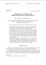
A surface of a hot plate made of grey cast iron used<br />
for the electric stove exhibits many brown stains (Figure<br />
1) after black oxide coating (blackening). The blackening<br />
[1] is mainly used to produce a protective dark<br />
(grey) oxide layer [2,3] on the surface consisting predominantly<br />
of magnetite (Fe 3 O 4 ); however, it also prevents<br />
against corrosion and abrasion, and since it has<br />
also decorative role the occurrence of brown stains on<br />
the surface is thus not acceptable [4]. Before blackening<br />
the grooves on the surface of the hot plate are made by<br />
turning [5-7] .<br />
The black oxide coating process of hot plate was<br />
held in the furnace at 650 °C. For the appropriate atmosphere<br />
for producing a thin oxide layer on the surface<br />
of grey cast iron the wood was burned [8]. The<br />
maximum temperature in the furnace of 650 °C is<br />
reached after four hours, while the whole process lasts<br />
eight hours.<br />
EXPERIMENTAL<br />
For the microstructural characterization of the brown<br />
stains on the surface of grey cast iron which have been<br />
observed after blackening a scanning electron microscope<br />
Jeol JSM 5610 equipped with energy dispersive<br />
x-ray spectrometer (EDXS) was used [9]. The accelerated<br />
voltage of electron beam was 20 keV. An x-ray diffraction<br />
analysis was also performed for phase identifi ca-<br />
Figure 1 Brown stains on the surface of grey cast iron after<br />
blackening<br />
tion. Thus, an x-ray diffractometer PANalytical X´Pert<br />
PRO (radiation wavelength CuKα 1 = 1,5406 Å) with Johansson<br />
monochromator for fl at samples has been used.<br />
RESULTS AND DISCUSSION<br />
A detailed observation of the surface of grey cast<br />
iron after blackening using scanning electron microscope<br />
revealed that the surface with brown stains (Figure<br />
1) is covered with whiskers [10-14] (Figure 2),<br />
while the surface where no brown stains have been observed<br />
shows typical oxide pattern (Figure 3) which refl<br />
ects grain orientation of the base material.<br />
Backscatter electron image (BEI) of the cross section<br />
of the sample covered with whiskers (Figure 4)<br />
shows, chemically, two different oxide layers on the<br />
base material (grey cast iron), i.e., the outer (light con-<br />
11
A. NAGODE et al.: STRUCTURAL AND THERMODYNAMIC ANALYSIS OF WHISKERS ON THE SURFACE...<br />
Figure 2 Surface of grey cast iron covered with whiskers; SEI<br />
Figure 3 Typical oxide pattern after black oxide coating; SEI<br />
trast) and the inner (dark contrast) oxide layers However,<br />
a detailed EDXS analysis (Table 1) shows that<br />
whiskers as well as the upper part of the outer oxide<br />
layer is composed of pure Fe-oxide, while in the lower<br />
oxide layer EDXS analysis indicates FeMn-oxides. The<br />
EDXS analysis of the inner oxide layer (dark contrast)<br />
confi rms the presence of Fe, Mn and Cr; however, the<br />
increased content of Si indicates that the inner layer is<br />
composed of Si-rich Fe(MnCr) oxide.<br />
In Figure 4 the internal oxidation of the matrix<br />
around the graphite fl akes near the surface can also be<br />
seen. The internal oxidation actually consists of iron<br />
oxidation (xFe + yO → Fe x O y ) as well as graphite oxidation<br />
(2C + O 2 → 2CO or C + O 2 → CO 2 ). The formation<br />
and growth of the Fe-oxide in the subsurface is<br />
promoted by oxygen penetration through the graphite<br />
boundaries with the metallic matrix [15, 16]. In order to<br />
show the element distribution on the cross section of the<br />
sample covered with whiskers an energy dispersive xray<br />
spectroscopy (EDXS) maps are presented. EDXS<br />
maps confi rm above mentioned results of EDXS quantitative<br />
analysis. Distribution of carbon shows graphite<br />
fl akes at the bottom of the image, however, at the top of<br />
the image the signal of C shows the signal C, Kα x-rays<br />
which come from the bakelite that the sample for metallographic<br />
preparation has been put in. The x-ray diffrac-<br />
Figure 4 Cross section of the sample covered with whiskers;<br />
BEI<br />
tion analysis was used for a phase identifi cation of the<br />
surface covered with whiskers as well as for the surface<br />
without them. The analysis showed that the only difference<br />
between two XRD patterns lies in the ratio of the<br />
peak intensities between the hematite (Fe 2 O 3 ) and the<br />
magnetite (Fe 3 O 4 ). Namely, a detail from the XRD spectrum<br />
(2 theta = 32 ° - 2 theta = 36 °) of the surface covered<br />
with whiskers shows a higher peak-intensity ratio<br />
between the hematite (Fe 2 O 3 ) and the magnetite (Fe 3 O 4 )<br />
(Figure 6a) in comparison to the x-ray diffraction pattern<br />
of the surface without whiskers (Figure 6b). Since<br />
the surface with brown stains is covered with whiskers<br />
this result indicates that the whiskers are composed of<br />
hematite (Fe 2 O 3 ).<br />
THERMODYNAMIC CALCULATIONS<br />
For the calculation of particular phase diagram, Figure<br />
7, the data for pure elements were taken from Dinsdale<br />
[17], for the substances data from Ansara [18].<br />
Thermodynamic assessments on the Fe-O phase dia-<br />
Fe, Kα Mn, Kα<br />
Cr, Kα Si, Kα<br />
O, Kα C, Kα<br />
Figure 5 EDXS maps of Fe, Mn, Cr, Si O and C<br />
12 METALURGIJA 52 (2013) 1, 11-14
A. NAGODE et al.: STRUCTURAL AND THERMODYNAMIC ANALYSIS OF WHISKERS ON THE SURFACE...<br />
Table 1 EDXS analysis of the sample covered with whiskers<br />
in cross section /wt. %<br />
Site of<br />
interest<br />
Fe O Mn Si Cr<br />
1 93,5 6,5 - - -<br />
2 95,9 4,1 - - -<br />
3 96,0 1,9 1,1 - -<br />
4 95,9 3,1 0,4 0,3 0,3<br />
5 95,8 0,6 0,7 2,2 0,6<br />
6 97,4 - 0,6 1,3 0,7<br />
Figure 6 A detail of XRD spectrum of the surface; a) covered<br />
with whisker; b) without whiskers<br />
gram were done by Sundman [19] and Selleby and Sundman<br />
[20]. The calculation of the phase diagram was<br />
done using Thermo-Calc software (TCW5).<br />
The calculations were performed using equation 1<br />
and equation 2. The activity of oxide was taken to be 1<br />
as in the case of pure metal. The standard state of the<br />
gas is 1 atm. The equation for oxidation of pure metal is<br />
given with equation 1:<br />
2u<br />
2<br />
Me(<br />
s)<br />
+ O2<br />
= MeuO<br />
(1)<br />
v(<br />
s)<br />
v<br />
v<br />
0<br />
−1<br />
0<br />
∆G<br />
= ∆G<br />
+ RT ln po2<br />
( eq.)<br />
= ∆G<br />
− RT ln po2<br />
( eq.)<br />
(2)<br />
METALURGIJA 52 (2013) 1, 11-14<br />
2Fe(s) + O 2 = 2FeO(s)<br />
∆G 0 = −529 800 + 113,0T (3)<br />
1,5Fe(s) + O 2 = 0,5Fe 3 O 4 (s)<br />
∆G 0 = −553 400 + 148,0T (4)<br />
4Fe 3 O 4 (s) + O 2 = 6Fe 2 O 3 (s)<br />
∆G 0 = −498 900 + 281,3T (5)<br />
6FeO(s) + O 2 = 2Fe 3 O 4 (s)<br />
∆G 0 = −624 400 + 250,2T (6)<br />
where ∆G(J) and ∆G 0 (J) represents the Gibbs energy<br />
change of the reaction when all reactants and products<br />
are at their respective arbitrarily states and the standard<br />
Gibbs energy of formation (equations 3-6). R is the gas<br />
constant (8,3144 Jmol -1 K -1 ), T temperature (K) and po 2<br />
(eq.) (atm) is equilibrium (dissociation) pressure of iron<br />
oxide. The calculations were done for equilibrium con-<br />
Figure 7 Fe-O phase diagram, and partial pressure of oxygen<br />
at 400 °C, 600 °C, 800 °C and 1000 °C<br />
ditions, ∆G = 0 Constant isobars at specifi c temperatures<br />
revealed large variations of dissociation pressures<br />
of iron oxides existing between different oxide regions.<br />
So, proper heating and cooling conditions (with controlled<br />
partial pressure-oxygen content inside the gas<br />
reservoir) are needed for controlled growth of oxides,<br />
Figure 7. If the value po 2 for a given atmosphere under<br />
consideration lies under the dissociation pressure of<br />
iron oxide po 2 (eq.), this oxide will dissociate into the<br />
oxygen and metal (or another oxide). On the contrary, if<br />
the value po 2 lies above the dissociation pressure of iron<br />
oxide po 2 (eq.), then the iron oxide is stable. So, increased<br />
partial pressure of oxygen relative to dissociation<br />
pressure at temperature of interest the formation of<br />
the hematite on the pre-existing magnetite is possible.<br />
The content of particular oxide (Fe 2 O 3 on Fe 3 O 4 ) is a<br />
time-dependant function.<br />
CONCLUSIONS<br />
Whiskers growth on the surface of hot plates made<br />
of grey cast iron caused brown stains and thus, aesthetically<br />
damaged the surface. Scanning electron microscope<br />
(SEM) showed that whiskers were growing from<br />
the top oxide layer on the surface of grey cast iron. An<br />
EDXS analysis confi rmed that the oxide on the surface<br />
of the grey cast iron consists, chemically, of three different<br />
types of oxides, i.e., whiskers and the outer oxide<br />
layer are pure Fe-oxide, below it is a narrow layer of<br />
FeMn-oxide, while the inner layer consists of Si-rich<br />
Fe(MnCr) oxide. An X-ray diffraction pattern of the<br />
surface covered with whiskers shows a higher Fe 2 O 3 /<br />
Fe 3 O 4 peak-intensity ratio according to the x-ray diffraction<br />
pattern of the surface without them. This indicates<br />
that the whiskers are from hematite (Fe 2 O 3 ).<br />
13
A. NAGODE et al.: STRUCTURAL AND THERMODYNAMIC ANALYSIS OF WHISKERS ON THE SURFACE...<br />
REFERENCES<br />
[1] N. Arab, M. Rahimi Nezhad Soltani, Journal of Applied<br />
Chemical Research, 9 (2009), 13-23.<br />
[2] M. Gojić, J. Črnko, M. Kundak, L. Kosec, Kovové Materiály,<br />
41 (2003), 158-166.<br />
[3] M. Bizjak, A. Zalar, P. Panjan, B. Zorko, B. Praček, Applied<br />
Surface Science, 253 (2007), 3977-3981.<br />
[4] A. Nagode, G. Klančnik, H. Schwarczova, B. Kosec, M.<br />
Gojić, L. Kosec, Engineering Failure Analysis, 23 (2012)<br />
1, 82-89.<br />
[5] J. Tušek, D. Klobčar, Journal of Mechanical Engineering,<br />
50 (2004) 2, 94-103.<br />
[6] I. Budak, M. Soković, M. Barišić, Measurement, 44 (2011)<br />
6, 1188-1200.<br />
[7] D. Klobčar, L. Kosec, B. Kosec, J. Tušek, Engineering Failure<br />
Analysis, 20 (2012) 1, 43 – 53.<br />
[8] M. Medved, V. Malenković, E. Dervarič, Technics Technologies<br />
Education Management, 6 (2011) 2, 247-255.<br />
[9] G. Kosec, A. Nagode, I. Budak, A. Antić, B. Kosec, Engineering<br />
Failure Analysis, 18 (2011) 1, 450-454.<br />
[10] F. Tholence, M. Norell, Oxididation of Metals, 69 (2008),<br />
13-36.<br />
[11] B. Schmid, N. Aas, R. Ødegård, Oxidation of Metals, 57<br />
(2002), 115-130.<br />
[12] R. L. Higginson, G. Green, Corrosion Science, 53 (2011),<br />
1690-1693.<br />
[13] J. W. Kim, J.W. Choi, D.B. Lee, Metals and Materials International,<br />
11 (2005), 131-134.<br />
[14] A. Ivanič, S. Lubej, R. Rudolf, I. Anžel, Science and Engineering<br />
of Composite Materials, 18 (2011) 3, 181-186.<br />
[15] J. Robertson, M.I. Manning, Materials Science and Technology,<br />
5 (1989), 741-753.<br />
[16] M. B. Lin, C. Jeng, A.A. Volinsky, Oxidation of Metals, 76<br />
(2011), 161-168.<br />
[17] A. T. Dinsdale, SGTE Data for Pure Elements, Calphad 15<br />
(4) (1991), 317-425.<br />
[18] I. Ansara, SGTE Substance Database (2000).<br />
[19] B. Sundman, Journal of Phase Eguilibrium, 12 (1991),<br />
127-140.<br />
[20] M. Selleby, B. Sundman, Calphad 20 (1996), 381-392.<br />
Note: The responsible translator for English language is Urška Letonja,<br />
MOAR, Podgora, Slovenia.<br />
14 METALURGIJA 52 (2013) 1, 11-14
P. MALATYŃSKA, J. GŁOWNIA<br />
CARBON CONTENT INFLUENCE<br />
ON THE PERITECTIC REACTION PATH IN STAINLESS STEELS<br />
P. Malatyńska, J. Głownia, AGH University of Science and Technology,<br />
Kraków, Poland<br />
METALURGIJA 52 (2013) 1, 15-18<br />
ISSN 0543-5846<br />
METABK 52(1) 15-18 (2013)<br />
UDC – UDK 669.146.536.42.669.141.25=111<br />
Received – Prispjelo: 2012-03-21<br />
Accepted – Prihvaćeno: 2012-07-30<br />
Original Scientifi c Paper – Izvorni znanstveni rad<br />
An important role for the peritectic reaction path in castings of stainless steel play small changes in a carbon content<br />
(e.g. from 0,02 to 0,06 % C), at maintaining constant chromium and nickel values. An infl uence of the carbon<br />
content on the peritectic reaction stages constitutes the subject of studies. The calculations of the steel solidifi cation<br />
pathways in the four-component system, of a constant chromium and nickel content of 18 % and 9 % – respectively<br />
and of various carbon content from 0,01 to 0,06 %, were performed. It was proved by means of the PANDAT<br />
program that the carbon concentration increases the Cr segregation and thereby changes the solidifi cation path<br />
under actual conditions.<br />
Key words: peritectic reaction, stainless steel, carbon content, segregation, simulation of solidifi cation.<br />
INTRODUCTION<br />
Investigations of the behaviour of the Fe-Cr18-Ni9<br />
system during the peritectic reaction occurrence were<br />
performed by means of the PANDAT program. Regardless<br />
of several studies concerning the peritectic reaction<br />
[1 – 8] it is still a not well known effect. In order to understand<br />
better the processes occurring during this reaction<br />
several calculations of the system, allowing the visualisation<br />
of this change, were performed. This reaction is<br />
of an essential meaning in modern casting, since it is considered<br />
to be the cause of surface defects such as cracks<br />
and deformations, especially in thin casting walls. An occurrence<br />
of longitudinal cracks on casting surfaces is related<br />
to volumetric changes and fractions of ferrite and<br />
austenite phases, while transverse cracks to the formation<br />
of austenite grains [1]. The peritectic reaction [1 – 4] described<br />
many times, divides the peritectic change into<br />
three stages: the main reaction, phase transformation and<br />
solidifi cation. Mechanisms of the reaction and transformation<br />
were characterised in detail by H. Kerr [4].<br />
Investigations of the solidifi cation of austenitic Fe-<br />
Cr-Ni steels will allow differentiating four solidifi cation<br />
forms, which depend on the initial phase and on further<br />
transformations in the solid phase [5]. The total solidifi -<br />
cation of the regular face-centred cubic phase, fcc, is<br />
called the A type, while the AF type [6] starts the solidifi<br />
cation process of the primary fcc phase, up to the fi nal<br />
stage of the eutectic reaction (fcc + bcc).<br />
The solidifi cation period of the primary body-centred<br />
cubic phase, bcc, up to the end of the eutectic reaction<br />
(bcc + fcc) is called the FA type. The total solidifi -<br />
cation of the bcc phase is marked as the F type. The total<br />
solidifi cation of the regular face-centred cubic, fcc (A<br />
type), phase depends on nickel, which stabilises this<br />
phase, whereas in case of the regular body-centred cubic,<br />
bcc (F type), phase chromium is the stabilizing element.<br />
For the A and AF solidifi cation types, at the primary<br />
solid phase growing, chromium contained in the<br />
alloy enriches interdendritic liquid causing an occurrence<br />
of the eutectic reaction (fcc + bcc) in the fi nal solidifi<br />
cation stage. The bcc phase is contained in the interdendritic<br />
zones of the formed eutectic in the retained,<br />
different morphology. For the FA and A solidifi cation<br />
types the interdendritic liquid is enriched in nickel,<br />
which causes the eutectic reaction occurrence (bcc +<br />
fcc), and the formed microstructure consists of the bcc<br />
phase dendrites surrounded by the fcc phase [6].<br />
EXPERIMENTAL PART<br />
Calculations of the Fe-Cr-Ni system were performed<br />
for the constant chromium (18 %) and nickel (9 %) content,<br />
at the variable carbon content (from 0,01 to 0,06<br />
%). The preformed examinations of the system were<br />
based on previous estimations made by Luoma [9],<br />
Hillert and Qiu [10] and Kundrad and Elliot [11]. The<br />
main aim of the investigations was the verifi cation in<br />
what way a small carbon content infl uences the fourcomponent<br />
system. The infl uence of chromium on the<br />
three-component Fe-Cr-Ni system in the peritectic reaction<br />
area is presented in Figure 1. This is the temperature<br />
range, specially considered in the paper.<br />
From among several calculated systems – solidifying<br />
within the peritectic reaction temperature – the following<br />
temperatures were selected for the analysis:<br />
1 515 ˚C, 1 500 ˚C, 1 490 ˚C, 1 480 ˚C and 1 4750˚C. In<br />
the fi rst of these temperatures: 1 515 ˚C, for lower carbon<br />
15
P. MALATYŃSKA et al.: CARBON CONTENT INFLUENCE ON THE PERITECTIC REACTION PATH IN STAINLESS STEELS<br />
Figure 1 Infl uence of chromium content on solidifi cation<br />
mode in Fe-Cr-Ni ternary system<br />
Figure 2 Solidifi cation course in temperature<br />
1 515 °C of Fe-Cr18-Ni9 system: A) 0,01 - 0,03 % C,<br />
B) 0,04 - 0,06 % C<br />
A)<br />
B)<br />
content (Figure 2 A), the visible, initial area of three<br />
phases (LIQUID + BCC_A2 + FCC_A1), i.e. the peritectic<br />
reaction, occurs at 6 % of chromium and 4 % of nickel,<br />
while for higher carbon content (Figure 2 B) – at approximately<br />
5 % of chromium and above 4 % of nickel.<br />
In a lower temperature: 1 500 ˚C and for 0,01 – 0,03<br />
% C (Figure 3 A), the peritectic reaction starts already at<br />
app. 11 % of chromium and 6% of nickel. However, lower<br />
carbon content the smaller BCC_A2 crystallisation<br />
area, which – in turn – decreases the peritectic reaction<br />
area (LIQUID + BCC_A2 + FCC_A1) and its further<br />
transformation. The three-phase area for 0,04 – 0,06 % C<br />
has a wider range, in a similar fashion as the transformation<br />
via the secondary FCC_A1 phase, while the hightemperature<br />
BCC_A2 range decreases (Figure 3 B).<br />
A successive shifting to higher chromium concentrations<br />
occurs during the solidifi cation at a temperature<br />
of 1 490˚C (Figure 4 A and B). The three-phase area<br />
decreases, in an analogous way, with the decreasing carbon<br />
content in the system and with increasing the hightemperature<br />
is also visible at a temperature of 1 480 °C<br />
(Figure 5 A and B). The larger this area BCC_A2 phase,<br />
16 METALURGIJA 52 (2013) 1, 15-18<br />
A)<br />
B)<br />
Figure 3 Solidifi cation course in temperature<br />
1 500 ˚C of Fe-Cr18-Ni9 system: A) 0,01 - 0,03 % C, B)<br />
0,04 - 0,06 % C
P. MALATYŃSKA et al.: CARBON CONTENT INFLUENCE ON THE PERITECTIC REACTION PATH IN STAINLESS STEELS<br />
METALURGIJA 52 (2013) 1, 15-18<br />
A)<br />
B)<br />
Figure 4 Solidifi cation course in temperature 1490 °C of Fe-<br />
Cr18-Ni9 system: A) 0,01 - 0,03 % C, B) 0,04 - 0,06 % C<br />
as a result of diffusion via the FCC_A1 phase. This decrease<br />
causes that the alloy has worse corrosion resistant<br />
and strength properties, especially in case of castings<br />
of diversifi ed wall thickness. It also leads to the<br />
increased segregation of carbon and chromium and to<br />
the formation of brittle phases, such as σ.<br />
The change of the peritectic transformation area the<br />
smaller the high-temperature BCC_A2 phase. The peritectic<br />
reaction area in Figure 5 A decreases and the<br />
FCC_A1 phase crystallising from the LIQUID surrounds<br />
the primary BCC_A2 phase. As a result of that,<br />
the LIQUID phase in the system disappears as a component<br />
of the peritectic reaction. Figure 5 B presents the<br />
area of two phases occurrence: LIQUID + BCC_A2 for<br />
higher carbon concentrations. During the peritectic reaction<br />
the increased FCC_A1 phase fraction causes the<br />
decrease of the high-temperature BCC_A2 phase.<br />
In a still lower temperature (1 475 °C), Figure 6 A,<br />
the LIQUID phase disappears and the areas of the LIQ-<br />
UID + BCC_A2 and LIQUID + FCC_A1 occurrence<br />
decrease. Thus, the slow disappearance of the threephase<br />
peritectic reaction takes place. However, the diffusion<br />
of carbon still occurs in the FCC_A1 phase and<br />
due to it, the three-phase peritectic area, but much<br />
smaller in size, still occurs in liquid containing from<br />
0,04 % to 0,06 % of carbon (Figure 6 B). It can be noticed,<br />
that at 0,06 % of the carbon content the BCC_A2<br />
area narrows to below 1 % of chromium and 1 % of<br />
nickel. This is the reason that after the fi nished crystallization<br />
this phase is – in the alloy microstructure – in<br />
the retained form only. The content of components stabilizing<br />
ferrite and austenite in the alloy decides on its<br />
size.<br />
CONCLUSIONS<br />
A)<br />
B)<br />
Figure 5 Solidifi cation course in temperature 1480 °C of Fe-<br />
Cr18-Ni9 system: A) 0,01 - 0,03 % C, B) 0,04 - 0,06 % C<br />
The peritectic reaction occurring in the Fe-Cr-Ni alloy<br />
is of a special meaning for the fi nal microstructure<br />
17
P. MALATYŃSKA et al.: CARBON CONTENT INFLUENCE ON THE PERITECTIC REACTION PATH IN STAINLESS STEELS<br />
and properties of cast steels. Several strength and corrosion<br />
resistant properties depend on its pathway. This<br />
reaction mainly depends on the alloying elements content<br />
and also – as it was shown in the presented here<br />
study – on the carbon content. It is worth emphasizing<br />
that such strong infl uence, on the three-phase area of the<br />
peritectic reaction and its further transformation, is exerted<br />
by such small differences in the carbon content<br />
(calculations were performed every 0,01 % of C). It was<br />
noticed, that the higher carbon content the wider area of<br />
the peritectic reaction occurrence. However, the following<br />
transformation of the BCC_A2 phase into FCC_A1<br />
increases its range. Unfortunately the BCC_A2 phase<br />
amount after the alloy solidifi cation depends on the peritectic<br />
reaction range. The BCC_A2 phase is very important<br />
due to its infl uence on corrosion resistance<br />
properties and formation of brittle phases.<br />
Acknowledgements<br />
The research program was performed within the<br />
Project: NSC No. N N508 624440 (2011-2013)<br />
REFERENCES<br />
[1] McDonald N.J., Sridhar S.: Journal of Materials Science,<br />
40(2005) 241 ÷ 2416.<br />
[2] Hillert M., Höglund L.: Materials Transactions, 40(1999)<br />
564 ÷ 566.<br />
[3] Hillert M., Höglund L.: Materials Transactions, 40(1999)<br />
567 ÷ 570.<br />
[4] Kerr H.W., Cisse J., Bolling G.F.: Acta Metallurgica,<br />
22(1974) 677 ÷ 686.<br />
[5] Koseki T., Flemings M.C.: Metallurgical and Materials<br />
Transactions A, 27A(1996) 3226 ÷ 3240.<br />
[6] Kalandyk B.: Archives of Foundry Engineering, Katowice<br />
– Gliwice 2011, 138 pp.<br />
[7] Fredriksson H.: Metal Science, 10(1976) 77 ÷ 86.<br />
[8] Fredriksson H., Stjerndahl J.: Metal Science, 16(1982) 575<br />
÷ 585.<br />
[9] Luoma R.: Acta Polytechnica Scandinavica, Chemical<br />
Technology Series No. 292, Helsinki 2002, 91 pp.<br />
[10] Hillert M., Qiu C.: Metallurgical Transaction A, 22.A(1991)<br />
2187 ÷ 2198.<br />
[11] Kundrad D.H., Elliot J.F.: Metallurgical Transaction A,<br />
19(1988) 899 ÷ 908.<br />
Note: The responsible translator for English language: “ANGOS”<br />
Translation Offi ce, Kraków, Poland<br />
18 METALURGIJA 52 (2013) 1, 15-18<br />
A)<br />
B)<br />
Figure 6 Solidifi cation course in temperature 1 475 ˚C of Fe-<br />
Cr18-Ni9 system: A) 0,01 -0 ,03 % C, B) 0,04 - 0,06 % C
K. KOCÚROVÁ, M. DOMÁNKOVÁ, M. HAZLINGER<br />
THE INFLUENCE OF CARBONITRIDING<br />
PROCESS ON MICROSTRUCTURE AND<br />
MECHANICAL PROPERTIES OF MICRO-ALLOYED STEEL<br />
K. Kocúrová, M. Dománková, M. Hazlinger Faculty of Materials Science<br />
and Technology Trnava, Slovak University of Technology Bratislava,<br />
Slovak Republic<br />
METALURGIJA 52 (2013) 1, 19-22<br />
ISSN 0543-5846<br />
METABK 52(1) 19-22 (2013)<br />
UDC – UDK 669.146.536.42.669.141.25=111<br />
Received – Prispjelo: 2012-04-16<br />
Accepted – Prihvaćeno: 2012-08-10<br />
Original Scientifi c Paper – Izvorni znanstveni rad<br />
The article deals with the analysis of carbonitrided samples of S460MC microalloyed thermo-mechanically treated<br />
steel. The steel surface was saturated with carbon and nitrogen at the temperature of 860 °C. The nitrogen-methanole<br />
atmosphere with Amonnia addition was used for surface saturation in the process of carbonitriding. Oil hardening<br />
and tempering at 200 °C/1 hour followed after the diff usion saturation of experimental steel sample. The surface<br />
layer was composed of martensite, retained austenite and fi ne carbides of alloying elements. This was demonstrated<br />
with light microscopy and confi rmed by TEM (transmission electron microscope). The paper also presents<br />
the results of chemical composition and hardness measurement.<br />
Key words: micro-alloyed steel, carbonitriding, microstructure, TEM, precipitates<br />
INTRODUCTION<br />
Carbonitriding is one of the surface hardening process<br />
of the materials where carbon and nitrogen diffuse<br />
into the surface of components in the temperature range<br />
850 ÷ 880 °C. The fi rst step is the saturation of surface<br />
in carbon and nitrogen, then the hardening and tempering<br />
steps follow [1-3]. This process is favourable compared<br />
with carburizing process, because it results in direct<br />
hardening from the saturation temperature, shortening<br />
the production cycle, reducing production costs and<br />
achieving the favourable performance of the surface<br />
layers [4]. Thermo-chemical treatment (carbonitriding)<br />
is used to increase surface hardness, surface resistance<br />
to wear and maintaining tough core of parts.<br />
Microalloyed steel is a class of steels group<br />
desig ned to achieve specifi c properties by controlled<br />
thermo-mechanical processing [5]. Microalloyed steels<br />
gain their strength due to the use of reinforcing of the<br />
grain boundary and precipitation hardening, which is<br />
achieved by the controlled rolling of steels with required<br />
chemical composition [6]. The yield strength of strength<br />
levels of two steels refl ects added strength coming from<br />
intragranular carbides present in microalloyed steel [7].<br />
EXPERIMENTAL<br />
METHODS AND USED MATERIAL<br />
The rolled strip of the microalloyed steel thickness<br />
of about 3 mm was used as a starting material. The<br />
S460MC steel is used for tools for cold forming, suita-<br />
ble for production of moldings, car chassis, etc. The aim<br />
of analysis was to obtain more detailed information of<br />
microalloyed steel after carbonitriding process. Experimental<br />
methods used in this investigation were: analysis<br />
of the chemical composition, hardness measurement<br />
and the microstructure analysis using light microscope<br />
and TEM.<br />
Analysis of chemical composition<br />
The chemical composition of the basic material<br />
S460MC in the core of the sample was measured with<br />
Spectrotest instrument. The measured chemical composition<br />
of the experimental steel satisfi es specifi cation in<br />
material list for used steel. The measured chemical<br />
composition of steel in this study is given in Table 1.<br />
Table 1 Chemical composition of S460MC steel / wt. %<br />
Chemical elements Material S460MC<br />
C 0,043 ± 0,030<br />
Si 0,052 ± 0,050<br />
Mn 1,510 ± 0,050<br />
P 0,015 ± 0,008<br />
S 0,005 ± 0,002<br />
Al 0,072 ± 0,060<br />
Ti 0,005 ± 0,002<br />
Nb 0,009 ± 0,001<br />
V 0,083 ± 0,075<br />
Fe base<br />
Microstructure analysis<br />
The microstructure of the steel sample S460MC was<br />
investigated using the light microscope, type NEO-<br />
PHOT 30 with attached CCD camera and software programme<br />
IMPOR PRO 32.<br />
19
K. KOCÚROVÁ ET AL.: THE INFLUENCE OF CARBONITRIDING PROCESS ON MICROSTRUCTURE AND MECHANICAL...<br />
The microstructure of the starting material of<br />
S460MC consisting from ferrite and a small amount of<br />
fi ne carbides is shown in Figure 1 [8, 9].<br />
The microstructure of the surface diffusion layer<br />
consists from martensite and retained austenite, which<br />
can be seen in Figure 2.<br />
Carbide-ferritic type of the microstructure can be seen<br />
in the transitional area diffusion layer of S460MC steel.<br />
This type of the microstructure is shown in Figure 3.<br />
Figure 1 The microstructure of the initial state of microalloyed<br />
thermo-mechanically treated steel S460MC<br />
Figure 2 The microstructure of surface diff usion layer<br />
Figure 3 The microstructure of the steel in the transitional<br />
area<br />
Figure 4 The microstructure of the core of the steel<br />
The core of the steel sample has a ferrite-pearlitic<br />
microstructure which is ilustrated in Figure 4.<br />
Today TEMs are probably the most effi cient and<br />
versatile tools for the characterization of materials over<br />
spatial ranges from the atomic scale, through the evergrowing<br />
‘nano’regime (from < 1 nm to ~ 100 nm) up to<br />
the micrometer level and beyond. The resolution of a<br />
TEM is given in terms of the classic Rayleigh criterion<br />
for VLM (visible-light microscope), which states that<br />
the smallest distance that can be resolved, δ, is given<br />
approximately by:<br />
0,61⋅λ<br />
δ = (1)<br />
µ ⋅ sinβ<br />
λ is the wavelength of the radiation, μ the refractive<br />
index of the viewing medium, and β the semi-angle of<br />
collection of the magnifying lens [10]. In the case of<br />
TEM we can simplify this equation to:<br />
⋅<br />
δ =<br />
β<br />
0,61<br />
(2)<br />
For more detailed experimental analysis of thermochemical<br />
treated S460MC steel (especially in terms of<br />
the microstructure of carbide particles) was used the<br />
transmission electron microscope JEOL 200CX with<br />
greater resolution ability. Carbon replicas were prepared<br />
from different areas of the sample (surface layer, transitional<br />
area of difussion layer and the materials core).<br />
The precipitates of carbide at the interface of the<br />
original martensitic needles can be seen in the microstructure<br />
of the surface layer of S460MC steel (Figure<br />
5). It can be also seen the retained austenite and lower<br />
bainite. The microstructure of the transitional area diffusion<br />
layer is composed of retained austenite and lower<br />
bainite, where the precipitates inside bainitic needles<br />
are presents (Figure 6). It can see the ferritic matrix at<br />
the core of the material in Figure 7. The grains of ferrite<br />
are polyedric in shape. The smaller pearlitic colonies,<br />
which are present on the grain boundaries and precipitated<br />
carbides can be observed in this area.<br />
20 METALURGIJA 52 (2013) 1, 19-22
K. KOCÚROVÁ ET AL.: THE INFLUENCE OF CARBONITRIDING PROCESS ON MICROSTRUCTURE AND MECHANICAL...<br />
Figure 5 The surface diff usion layer of S460MC steel treated<br />
by carbonitriding, diff raction pattern of particles<br />
identifi ed M3C – type precipitates TEM of carbon<br />
extraction replicas<br />
Figure 6 The transitional area diff usion layer of the<br />
carbonitrided S460MC steel, TEM of carbon<br />
extraction replicas<br />
Figure 7 The core of S460MC steel, diff raction pattern of the<br />
particles identifi ed MX – type precipitates, TEM of<br />
carbon extraction replicas<br />
Hardness measurement<br />
The hardness on the surface of the carbonitrided<br />
sample was measured on a fl at area by method Vickers<br />
with loading 9,81 N. In this experiment were performed<br />
5 measurements and their results are in Table 2.<br />
METALURGIJA 52 (2013) 1, 19-22<br />
Figure 8 Graph of the hardness in the cross-section of the<br />
steel<br />
Table 2 Measured hardness on surface of S460MC steel<br />
Number of measurement Hardness<br />
HV1<br />
1 762<br />
2 757<br />
3 751<br />
4 772<br />
5 764<br />
In cross-section of sample, which was thermo-chemical<br />
treated, the course of hardness by Vickers method,<br />
with a micrometric shift of a table, loading 9,81 N was<br />
performed. From measured values of hardness was<br />
determined the depth of hardenability (or thickness of<br />
layer) in accordance with DIN EN ISO 2639 [11]. The<br />
depth corresponds to the value 0,4 mm (Figure 8).<br />
RESULTS<br />
The analysis of thermo-chemical treated sample<br />
confi rmed that it can be achieved surface layer with<br />
high hardness by carbonitriding process. The average<br />
value of hardness measured on the surface of carbonitrided<br />
sample was 761 ± 8 HV1. Determined hardenability<br />
corresponds to the value 0,4 mm. The thickness of<br />
diffusion layer (approx. 0,3 mm) can be achieved in a<br />
shorter time of carbonitriding (compared with carburizing<br />
process). This is possible due to the presence of<br />
nitrogen in the furnace atmosphere, the nitrogen increases<br />
the rate of diffusion of carbon in the material. The<br />
sample of used steel S460MC had fi ne-grained microstructure.<br />
The carbonitriding process (860 °C) does not<br />
avoid the unwanted coarsening of the grain. By the process<br />
is therefore possible to obtain the diffusion layer on<br />
the surface of a material with favorable functional characteristics<br />
[12]. The sample structure was investigated<br />
using light microscopy and transmission electron microscope<br />
(TEM). The martensite, retained austenite and<br />
carbide precipitates were seen in the surface diffusion<br />
layer of the sample. The core of steel consisted of the<br />
ferritic matrix and the grain boundaries excluded pearli-<br />
21
K. KOCÚROVÁ ET AL.: THE INFLUENCE OF CARBONITRIDING PROCESS ON MICROSTRUCTURE AND MECHANICAL...<br />
te. In this study were identifi ed two types of the precipitates:<br />
M 3 C and MX. The M 3 C and MX precipitates were<br />
observed in carbonitriding layer and core of the S460MC<br />
steel.<br />
CONCLUSION<br />
The obtained results show that the surface modifi cation<br />
of carbonitriding in nitrogen-methanole atmosphere<br />
with the Amonnia addition has succeedded to improve<br />
the surface hardness of the micro-alloyed steels. The<br />
presence of alloying elements (Ti, Nb, V) in steel results<br />
in a positive effect of the microstructure (fi ne grains)<br />
and it improves the mechanical properties (hardness,<br />
strength).<br />
Acknowledgement<br />
This contribution/publication is the result of the<br />
project implementation: CE for the development and<br />
application of diagnostic methods in the processing of<br />
metallic and non-metallic materials, ITMS code<br />
26220120048, supported by the Research & Development<br />
Operational Programme funded by the ERDF.<br />
REFERENCES<br />
[1] K. H. Prabhudev, Handbook of heat treatment of steels,<br />
Tata McGraw-Hill Publishing Company Limited, New<br />
Delphi, 2008, pp. 386-387.<br />
[2] G. E. Totten, K. Funatani, L. Xie, Handbook of metallurgical<br />
process design, Marcel Dekker, Inc., New York, 2004,<br />
pp. 507-509.<br />
[3] P. Skočovský, O. Bokůvka, R. Konečná, E. Tillová, Náuka<br />
o materiáli pre odbory strojnícke, EDIS, Žilina, 2001, pp.<br />
75-76.<br />
[4] M. Hazlinger, Proceedings, TRANSFER 2007. Využívanie<br />
nových poznatkov v strojárskej praxi: 9. medzinárodná<br />
vedecká konferencia, Digital Graphic, Trenčín, 2007, pp.<br />
187-190.<br />
[5] J. W. Martin, Concise encyclopedia of the mechanical properties<br />
of materials, Elsevier Science, UK Oxford, 2007,<br />
pp. 418.<br />
[6] P. Švec, Konštrukčné materiály, Nakladateľstvo STU, Bratislava,<br />
2010, pp. 45-46.<br />
[7] T. H. Courtney, Mechanical Behavior of Materials, Waveland<br />
Press Inc., Illinois, 2005, pp. 225-227.<br />
[8] M. Durand-Charre,Microstructure of steels and cast irons,<br />
Springer, Paris, 2003, pp. 170-172.<br />
[9] H. K. D. H. Bhadeshia, R. W. K. Honeycombe, Steels microstructure<br />
and properties, Elsevier Ltd., UK Oxford,<br />
2006, pp. 100-109.<br />
[10] D. B. Williams, C. B. Carter, Transmission Electron Microscopy:<br />
A Textbook for Materials Science, Springer,<br />
2009, pp. 3-5.<br />
[11] DIN EN ISO 2639: Bestimmung und Prüfung der Einsatshärtungtiefe,<br />
Deutsche Fassung, 2002.<br />
[12] K. Kocúrová, M. Hazlinger, Proceedings, Materials Engineering,<br />
Faculty of Mechanical Engineering, University,<br />
Žilina, 2010, pp. 29-33.<br />
Note: The responsible for English language is Bibiana Gondeková the<br />
interpreter/translator from Banská Bystrica, Slovak Republic<br />
22 METALURGIJA 52 (2013) 1, 19-22
A. KAWAŁEK, J. RAPALSKA-NOWAKOWSKA, H. DYJA, B. KOCZURKIEWICZ<br />
PHYSICAL AND NUMERICAL MODELLING OF HEAT TREATMENT<br />
THE PRECIPITATION-HARDENING COMPLEX-PHASE STEEL (CP)<br />
A Kawałek, J. Rapalska-Nowakowska, H. Dyja, B. Koczurkiewicz, Faculty<br />
of materials Processing Technology and Applied Physics Częstochowa<br />
University of Technology, Częstochowa, Poland.<br />
METALURGIJA 52 (2013) 1, 23-26<br />
ISSN 0543-5846<br />
METABK 52(1) 23-26 (2013)<br />
UDC – UDK 669.1:621.78:519.876.5=111<br />
Received – Prispjelo: 2012-05-10<br />
Accepted – Prihvaćeno: 2012-08-25<br />
Original Scientifi c paper – Izvorni znanstveni rad<br />
The article presents the results of physical and numerical modelling of the processes of thermo- plastic treatment of<br />
an experimental complex-phase (CP) steel. Numerical tests were carried out using a commercial software program,<br />
ThermoCalc. Based on the obtained test results, the austenitization temperature was established. Physical modelling<br />
was performed using a DIL 805A/D dilatometer and the Gleeble 3800 system. The characteristic temperatures<br />
of the steel and the primary austenite grain size were determined. The test pieces were also subjected to metallographic<br />
examinations and Vickers hardness tests. The obtained results served for building an actual CCT diagram for<br />
the steel tested.<br />
Key words: CP steels, microstructure evolution, physical modelling, CCT diagrams<br />
INTRODUCTION<br />
The development of the automotive industry urges<br />
designers to focus their activities on reducing the mass<br />
of cars to be manufactured, resulting in a signifi cant reduction<br />
of fuel consumption and emissions of harmful<br />
exhaust gas to the atmosphere. The consequence of this<br />
is searching for new constructional materials for the<br />
manufacture of sheet metal of high strength and engineering<br />
deformability, which will assure lightweight<br />
and tough car bodies to be obtained [1 - 2]. This direction<br />
is consistent with the general trend development of<br />
metallurgy in Poland [3]. Among modern car body<br />
steels, two group of steels can be distinguished. The<br />
fi rst group is made up of conventional High-Strength<br />
Steels (HSS).<br />
This includes: Interstitial-Free (IF) steels, Isotropic<br />
Steels (IS), Bake Hardened (BH) steels, C-Mn (carbonmanganese)<br />
steels, and High-Strength Low-Alloy (HSLA)<br />
steels. The second group consists of Advanced High-<br />
Strength Steels (AHSS): Dual Phase (DP) steels; Complex<br />
Phase (CP) steels; TRIP (Transformation Induced Plasticity)<br />
steels; and TMS (martensitic steels) [4 - 8].<br />
CP steels are characterized by their tensile strength<br />
at a level of approx. 800 MPa, and quite often even<br />
more. The high strength of steel is achieved due to the<br />
contents of fi ne-grained ferrite and interstitial bainite in<br />
the microstructure and the dispersion hardening by precipitates<br />
of carbides and nitrides. To obtain fi ne-grained<br />
precipitates, additions of niobium, titanium or vanadium<br />
are used. Steels of this type are distinguished by<br />
good deformability and high capability to absorb energy<br />
during a collision. Thanks to these properties, CP steels<br />
fi nd application as a material for production of construction<br />
elements absorbing the energy of collisions, especially<br />
side crashes.<br />
TEST MATERIAL<br />
AND TESTING METHODOLOGY<br />
Tests were carried out on an experimental complex<br />
phase steel, whose chemical composition is given in Table<br />
1.<br />
Table 1 Chemical composition of the steel / wt %<br />
C Mn Si Cr Ni Ti Cu N<br />
0,08 1,5 0,4 0,3 0,2 0,10 0,2 0,003<br />
The melt was made under laboratory conditions in a<br />
VSG100S vacuum furnace with a crucible capacity of<br />
100 kg, and was cast in vacuum into a 100 x 100 mm<br />
inner cross-section ingot mould. The obtained ingot was<br />
forged into square and round bars and then softening<br />
heat treatment was carried out.<br />
Numerical studies were carried out using the Thermo-Calc<br />
program. The austenitizing temperature of the<br />
test steel, which assured the dissolution of alloy additions<br />
in the solution, was determined based on the<br />
chemical composition using this program. On this basis,<br />
the diagram of equilibrium of the test steel with the carbon<br />
content varying in the range of 0 - 0,12 % and variation<br />
in the contents of individual phases as a function<br />
of temperature was plotted.<br />
For carrying out physical simulations of heat treatment,<br />
a DIL 805A/D dilatometer was used. For the tests<br />
10 mm-long and 5 mm-diameter cylindrical samples<br />
23
A. KAWAŁEK et al.: PHYSICAL AND NUMERICAL MODELLING OF HEAT TREATMENT...<br />
were used. In the fi rst place, the effect of austenitizing<br />
temperature on the primary austenite grain size was examined.<br />
To this end, the samples were heated up to a<br />
temperature in the range of 900 – 1 250 °C with a step<br />
of 50 °C and at a rate of 5 °C/s, soaked at that temperature<br />
for 30 minutes, and then rapid cooling was applied<br />
to assure that the structure was frozen. The austenite<br />
grain size on samples was determined by a comparative<br />
method using the normalized standard scale conforming<br />
to standard PN-EN ISO643:2003.<br />
The values of the characteristic temperatures A c1 ,<br />
A c3 , A r1 and A r3 during heating and cooling were determined.<br />
The samples were heated up and cooled down in<br />
a continuous manner at a constant rate of 3 °C/min. The<br />
analysis of dilatometric patterns recorded during heating<br />
and cooling was made following the procedure set<br />
out in standard PN-68/H-04500. The determined values<br />
of temperatures A c3 provided a basis for establishing the<br />
value of austenitizing temperature during conducting<br />
the dilatometric tests.<br />
To determine the CCT diagram, the samples were<br />
heated up to a temperature of 940 °C at a heating rate of<br />
3 °C/s, soaked at that temperature for 300 s and then<br />
cooled down to ambient temperature at varying cooling<br />
rates. The outcome of the tests is a series of dilatometric<br />
patterns illustrating the variation of sample length as a<br />
function of temperature. After the heat treatment physical<br />
simulations, the samples were subjected to metallographic<br />
examination to disclose the structure formed,<br />
and then Vickers hardness tests were performed.<br />
To determine the effect of temperature and strain rate<br />
on the yield stress of the steel, a high-temperature compression<br />
test was carried out. The tests were conducted<br />
using a simulator of metallurgical processes Gleeble. The<br />
σ-ε curves were determined for the actual strain of ε = 1.<br />
The samples were resistance heated in vacuum to a temperature<br />
of 1 150 °C at a heating rate of 5 °C/s, soaked at<br />
that temperature for 60 s, and then cooled down to a plastic<br />
strain temperature of 850 - 1 150 °C. The compression<br />
of the samples was conducted at a strain rate of ε = 0,1;<br />
1,0 and 10 s -1 , respectively.<br />
TEST RESULTS AND THE DISCUSSION<br />
Based on the chemical composition, the austenitizing<br />
temperature of the test steel was determined. For<br />
this purpose, the Thermo-Calc program was used. The<br />
program served for constructing the diagram of equilibrium<br />
of the steel with carbon content varying in the<br />
range 0 - 0,12 % (Figure 1).<br />
The data in Figure 1 shows that up to a temperature<br />
of approx. 880 °C, a multi-component structure exists<br />
in the steel. It is composed of ferrite, austenite, cementite,<br />
MC-type carbides and manganese sulphide. Above<br />
that temperature, only austenite and manganese sulphide<br />
occur in the structure.<br />
The austenite grain size in the initial state was determined<br />
by a comparative method using the normalized<br />
Figure 1 Equilibrium diagram for steel with carbon content<br />
varying in the range of 0 – 0,12 %<br />
Figure 2 Eff ect of austenitizing temperature on the primary<br />
austenite grain size<br />
scale of standards in accordance with standard PN-EN<br />
ISO 643:2003, and was found to be 9 μm.<br />
The results of tests for the effect of austenitizing<br />
temperature in the range of 900 – 1 250 °C on the γ<br />
phase grain growth are illustrated in Figure 2.<br />
Figure 3 shows the revealed primary austenite grain<br />
boundaries in the test steel, as quenched from a temperature<br />
of 1 200 °C and 950 °C, respectively.<br />
The performed tests found that samples austenitized<br />
in the temperature range of 900 - 1 050 °C were characterized<br />
by fi ne austenite grains from 11 to 22 µm in size.<br />
This indicates that for austenitizing temperatures below<br />
1 050 °C the steel maintains a fi ne-grained structure.<br />
For a sample austenitized at 1 100 °C, the austenite<br />
grain size was determined to be 117 µm, which defi -<br />
nitely deviates from the remaining determined sizes. As<br />
indicated by the data in Figure 3, the accelerated austen-<br />
Figure 3 Primary austenite grain boundaries in steel<br />
quenched from a temperature of: a) 1 200 °C,<br />
50 x, b) 950 °C, 100 x<br />
24 METALURGIJA 52 (2013) 1, 23-26
Figure 4 Structure of the test steel: a) ferritic-bainitic,<br />
obtained after cooling at a rate of 30 °C/s; b)<br />
bainitic-martensitic, with a slight amount of ferrite,<br />
obtained after cooling at a rate of 80 °C/s; 1000 x<br />
ite grain growth occurs only after the temperature of<br />
1 100 °C is exceeded.<br />
The characteristic temperatures obtained from the<br />
analysis of dilatometric patterns: A c1 = 740 °C, A c3 = 889<br />
°C, A r1 = 655 °C, A c1 = 811 °C.<br />
The austenitizing temperature for carrying out physical<br />
simulations for the test steel was assumed to be T A<br />
= 940 ºC (A c3 + 40 – 50 o C).<br />
The samples after physical simulations were subjected<br />
to metallographic examination to reveal the<br />
structure formed (Figure 4).<br />
Vickers hardness tests were also performed (Table 2).<br />
Table 2 Phase transformation temperatures and the<br />
hardness of the test steel as cooled from a<br />
temperature of 940 °C<br />
Cooling<br />
rates/ ºC/s<br />
METALURGIJA 52 (2013) 1, 23-26<br />
Characteristic<br />
temperatures / ºC<br />
150 F = 715, F = B = 650,<br />
s f s<br />
B = 490, M = 411, M = 290<br />
f s f<br />
100 F = 712, F = B = 660,<br />
s f s<br />
B = 4 85, M = 410, M = 286<br />
f s f<br />
80 F =720, F = B = 670,<br />
s f s<br />
B = 505, M = 410, M = 330<br />
f s f<br />
50 F = 733, F = B = 680,<br />
s f s<br />
B = 479, M = 418, M = 348<br />
f s f<br />
A. KAWAŁEK et al.: PHYSICAL AND NUMERICAL MODELLING OF HEAT TREATMENT...<br />
Hardness<br />
HV<br />
321<br />
317<br />
257<br />
230<br />
30 F = 715, F = B = 650, B = 432 s f s f 188<br />
10 F = 800, F = P = 755,<br />
s f s<br />
P = B = 672, B = 550<br />
f s f<br />
156<br />
1 F = 800, F = P = 745, P = 625 s f s f 151<br />
0,1 F = 796, F = P = 750, P = 664 s f s f 140<br />
The data in Table 2 shows that bainite-containing<br />
structures are obtained by cooling at cooling rates of v<br />
= 10 – 150 ºC/s. A three-phase structure composed of<br />
ferrite, martensite and bainite is obtained by cooling at<br />
cooling rates higher than v = 30 °C/s.<br />
Based on the performed analysis and obtained results,<br />
a CCT diagram was plotted (Figure 5).<br />
The developed CCT diagram enables the temperatures<br />
of the beginnings and ends of phase transformations<br />
occurring during continuous cooling of complex-phase<br />
steel to be red out with a high accuracy. It provides also<br />
the capability to determine the cooling rates that assure<br />
the formation of the desirable three-phase structure.<br />
To determine the effect of deformation temperature<br />
and strain rate on the yield stress of the test steel, a hightemperature<br />
compression test was carried out using the<br />
Gleeble 3800 metallurgical process simulator. Figures 6<br />
Figure 5 CCT diagram for the test steel<br />
Figure 6 Eff ect of deformation temperature on the σ-ε curves<br />
for the test steel deformed at a rate of 0,1 s -1<br />
- 8 show diagrams illustrating the effect of deformation<br />
temperature on the shape of the σ-ε curves for a varying<br />
strain rate of ε = 0,1; 1,0 and 10 s-1 , respectively.<br />
The values of strain and yield stress were calculated<br />
from relationship (1) and (2), respectively.<br />
2 h<br />
= ln<br />
(1)<br />
3 h0<br />
where:<br />
h – height of the sample during plastic deformation,<br />
h – initial sample height.<br />
0<br />
Figure 7 Eff ect of deformation temperature on the σ-ε curves<br />
for the test steel deformed at a rate of 1 s -1<br />
25
A. KAWAŁEK et al.: PHYSICAL AND NUMERICAL MODELLING OF HEAT TREATMENT...<br />
Figure 8 Eff ect of deformation temperature on the σ-ε curves<br />
for the test steel deformed at a rate of 10 s -1<br />
3 F<br />
p = (2)<br />
2 wb<br />
where: F – force measured during the course of plastic<br />
deformation, w – anvil width, b – sample width<br />
From the data in Figures 6 - 8 it is found that, for the<br />
test steel, the dynamic recrystallization occurs only at a<br />
strain rate of 0,1 s-1 . It is also fund that, for the steel grade<br />
tested (Figures 7 and 8), the effect of strain rate, in the<br />
range of values of 1 s-1 and 10 s-1 and in the temperature<br />
range of 850 - 1150°C, on the yield stress is small.<br />
The obtained curves will provide a basis for the development<br />
of the technology of rolling sheet metal of<br />
the steel grade investigated.<br />
SUMMARY<br />
Based on the investigation carried out, the following<br />
fi ndings and conclusions have been made:<br />
- for the steel grade examined, the austenitization<br />
temperature equal to T A = 950 ºC should be assumed;<br />
- the most desirable structures for the steel investigated<br />
are the ones containing bainite. During cooling<br />
from the austenitization temperature of T A =<br />
950 ºC, a three-phase structure containing ferrite,<br />
martensite and bainite is obtained with cooling at<br />
cooling rates in the range of v = 30 – 150 ºC/s;<br />
- the numerical and physical simulations complexphase<br />
steel heat treatment, which were carried out<br />
within this study, have enabled the actual CCT diagram<br />
to be constructed. This constitutes one of the<br />
elements providing the basis for developing the<br />
technology of rolling sheet metal of the steel grade<br />
investigated.<br />
REFERENCES<br />
[1] A. Jambor, M. Beyer: New cars- New materials, Materials<br />
& Design 18 (1997) 4/6, 203 - 209.<br />
[2] E. Hadasik: Modelowanie procesu walcowania blach na<br />
gorąco z nowoczesnych gatunków stali karoseryjnej, Hutnik-<br />
Wiadomości Hutnicze 75 (2008) 12, 707 – 713.<br />
[3] Z. Skuza, R. Prusak, C. Kolmasiak: Restructuring of the<br />
metallurgical industry in the aspect of economics system<br />
changes and integration with the eurepean union, <strong>Metalurgija</strong><br />
46 (2007) 3, 221 – 224.<br />
[4] F. Grosman: Nowoczesne blachy stalowe na elementy<br />
karoserii w świetle projektu ULSAB-AVC, Hutnik-<br />
Wiadomości Hutnicze 70 (2003) 7, 302 – 307.<br />
[5] J. Senkara: Współczesne stale karoseryjne dla przemysłu<br />
motoryzacyjnego i wytyczne technologiczne ich zgrzewania,<br />
Przegląd Spawalnictwa 81 (2009) 11, 3 – 7.<br />
[6] J. Adamczyk, A. Grajcar: Blachy stalowe o strukturze wielofazowej<br />
dla przemysłu samochodowego, Hutnik-<br />
Wiadomości Hutnicze 72 (2005) 3, 170 – 176.<br />
[7] St. Turczyn, M. Dziedzic: Walcowanie blach karoseryjnych<br />
z nowej generacji stali, Hutnik- Wiadomości Hutnicze<br />
69 (2002) 4, 126 – 132.<br />
[8] M. Dziedzic, St. Turczyn: Taśmy ze stali wielofazowych<br />
dla przemysłu samochodowego, Hutnik- Wiadomości Hutnicze<br />
70 (2003) 4, 153 – 158.<br />
Note: The responsible translator for English language is Czesław Grochowina,<br />
Poland.<br />
26 METALURGIJA 52 (2013) 1, 23-26
M. BURZIĆ, M. MANJGO, D. KOZAK, R. PROKIĆ-CVETKOVIĆ, O. POPOVIĆ<br />
METALURGIJA 52 (2013) 1, 27-31<br />
ISSN 0543-5846<br />
METABK 52(1) 27-31 (2013)<br />
UDC – UDK 669.15:620.178.3=111<br />
THE EFFECTS OF DYNAMIC LOAD ON<br />
BEHAVIOUR OF WELDED JOINT A-387 Gr. 11 ALLOYED STEEL<br />
Received – Prispjelo: 2012-03-21<br />
Accepted – Prihvaćeno: 2012-07-15<br />
Original Scientifi c Paper – Izvorni znanstveni rad<br />
The in-service behaviour of alloyed steel A-387 Gr. 11 Class 1, for pressure vessels, used for high temperature applications,<br />
depends on the properties of its welded joint, with parent metal (BM), heat-aff ected-zone (HAZ) and weld<br />
metal (WM), as constituents. Charpy testing of BM, WM and HAZ, together with, determination of the parameters of<br />
fatigue-crack growth and fatigue threshold ΔK th was used, in order to understand, how heterogeneity of structure<br />
and diff erent mechanical properties of welded joint constituents aff ect on crack initiation and propagation.<br />
Key words: alloyed steel A-387 Gr. 11, fatigue, impact energy, Paris relationship<br />
INTRODUCTION<br />
Exploitation properties of A-387 Gr. 11 Class 1 alloyed<br />
steel, designed for manufacture of pressure vessels<br />
operating at elevated temperatures and pressures,<br />
largely depend on properties of the critical zones of a<br />
welded joint. Heat-affected zone (HAZ) and weld metal<br />
(WM) are latent locations of crack initiation, i.e. the locations<br />
where local brittle zones to whom crack initiation<br />
is attributed could be formed [1].<br />
For better understanding of the causes and modes of<br />
crack initiation and crack growth in welded joints of<br />
steel designed for operation at elevated temperatures<br />
and under high pressure, it is necessary to establish how<br />
the heterogeneity of structure and mechanical properties<br />
of a welded joint affects crack initiation and growth,<br />
and to quantify the parameters controlling local-strain<br />
behaviour and crack growth.<br />
The aim of this investigation is to assess the effects<br />
of heterogeneity of structure and mechanical properties<br />
of base metal and components of the welded joint of<br />
A-387 Gr.11 Class 1 steel on crack initiation and growth,<br />
as well as on the parameters of fatigue-crack growth<br />
(da/dN and ΔK th ) at elevated temperature of 540 °C,<br />
based on the results obtained [1].<br />
MATERIAL<br />
For testing, the sample of a welded joint of A-387<br />
Gr. 11 Class 1 steel, with weld metal in the middle (double<br />
U-shaped weld), was used, the dimensions of which<br />
M. Burzić, R. Prokić-Cvetković, O. Popović, University of Belgrade,<br />
Faculty of Mechanical Engineering, Belgrade, Serbia<br />
M. Manjgo, Faculty of Mechanical Engineering, Mostar, Bosnia and Herzegovina<br />
D. Kozak, J. J. Strossmayer University of Osijek, Mechanical Engineering<br />
Faculty in Slavonski Brod, Croatia<br />
were 350 x 500 x 96 mm. Chemical composition of<br />
A-387 Gr. 11 Class 11 is presented in Table 1 [2]. The<br />
procedure for testing at elevated temperature of 540 °C<br />
is defi ned by the standard EN 10002-5 [3]. The results<br />
of tensile test of mechanical properties of A-387 Gr. 11<br />
Class 1 steel at operating tempera-ture are presented in<br />
Table 2 [2].<br />
Table 1 Chemical composition of tested material [2]<br />
Chemical composition / mas. %<br />
C Si Mn P S Cr Mo<br />
0,15 0,29 0,54 0,022 0,011 0,93 0,47<br />
Table 2 Results of tensile test [2]<br />
R p0,2 / MPa R m / MPa A / %<br />
220 280 36<br />
Welding of sheets new and exploited BM was conducted<br />
in two phases, as follows:<br />
– root run – by manual arc procedure, using a plated<br />
electrode LINCOLN Sl 19G (AWS: E8018-B2),<br />
– fi lling – by arc welding using powder protection,<br />
where the wire designated as LINCOLN LNS 150<br />
and powder LINCOLN P230 were used as fi ller<br />
metals.<br />
Chemical composition of used electrode LINCOLN<br />
Sl 19G (FM A) and wire LINCOLN LNS 150 (FM B)<br />
according to attest documen-tation is presented in Table<br />
3. Main mechanical properties according to attest documentation<br />
are presented in Table 4.<br />
Table 3 Chemical composition of fi ller metal [4]<br />
Filler<br />
Metal<br />
Chemical Composition / mass %<br />
C Si Mn P S Cr Mo<br />
FM A 0,08 0,045 0,35 0,025 0,025 1,10 0,50<br />
FM B 0,11 0,18 0,37 0,020 0,020 1,04 0,47<br />
27
M. BURZIĆ et al.: THE EFFECTS OF DYNAMIC LOAD ON BEHAVIOUR OF WELDED JOINT A-387 Gr. 11 ALLOYED STEEL<br />
Table 4 Mechanical properties of fi ller metal [4]<br />
Filler Metal R p0,2 / MPa R m / MPa A / % KV / J<br />
FM A 505 640 23 > 95<br />
FM B 490 610 26 > 100<br />
RESULTS AND DISCUSSION<br />
Testing by bending induced by impact effect of force<br />
on notched specimen can provide an explanation of material<br />
behaviour for disrupted strain. Determination of<br />
operation leading to fracture under established test conditions<br />
most frequently is used for current control of<br />
quality and homogeneity of the material, as well as of<br />
its treatment. This test procedure provides the possibility<br />
to establish susceptibility to brittle fracture, i.e. susceptibility<br />
to the increase of brittleness during exploitation<br />
(aging) [5].<br />
Impact testing of the notched specimens in base metal<br />
(BM), weld metal (WM) and heat-affected zone (HAZ)<br />
on the side of exploited BM in 540 °C, was conducted in<br />
order to dete-rmine total impact energy, as well as the<br />
components of the energy crack initiation and crack<br />
propagation. Test procedure and the shape and dimensions<br />
of the specimens, are defi ned by standard EN<br />
10045-1 [6]. Position of the notch relative to the welded<br />
joint is defi ned by the standard EN 875 [7]. The testing<br />
itself was conducted on instrumented Charpy pendulum.<br />
The results of testing are presented in Table 5.<br />
Table 5 The values of impact energy for tested BM and<br />
welded joint<br />
Spec.<br />
Design.<br />
Tot. Impact<br />
Energy,<br />
A uk / J<br />
Energy of Crack<br />
Initiat. A I / J<br />
Energy of<br />
Crack propag.<br />
A P / J<br />
BM-1 119 51 68<br />
BM-2 109 49 60<br />
BM-3 115 50 65<br />
WM-1 141 62 78<br />
WM-2 132 59 73<br />
WM-3 137 60 77<br />
HAZ-1 96 44 52<br />
HAZ -2 79 39 40<br />
HAZ -3 85 42 43<br />
Typical diagrams force-time and energy–time obtained<br />
by testing of the specimens designated by BM-1,<br />
WM-1 and HAZ-1 at operating temperature are given in<br />
Figures 1 through 3.<br />
Structural life is expressed through crack driving<br />
time. To determine exploitation life means to predict<br />
crack driving time. Thus it has been concluded that sharp<br />
stress concentrators under conditions of variable loading<br />
after certain number of cycles result in crack initiation<br />
and its propagation if the fatigue threshold, ΔK th , is exceeded.<br />
As the structure under certain loading conditions,<br />
as a rule, would not be jeopardized until the crack reaches<br />
critical dimensions, exploitation of a pre-cracked struc-<br />
ture can be allowed even during the period of crack<br />
growth, on condition that it had already been subjected to<br />
preliminary analysis. Knowledge on the crack -growth<br />
rate and its dependence on affecting loading is essential<br />
for the decision on further exploitation [8].<br />
Considering the fact that the stress fi eld at the crack<br />
tip is characterized by singularity, it would be best to<br />
express the effect of the stress-rate through the stressintensity<br />
factor.; as this is the case of variable loading,<br />
varying from highest to lowest value it would be most<br />
appropriate to describe it by the range of the stress-intensity<br />
factors, ΔK.<br />
20 Specimen BM - 1<br />
0<br />
0<br />
0 1 2 3 4 5 6 7 8<br />
T i m e / ms<br />
28 METALURGIJA 52 (2013) 1, 27-31<br />
F o r c e / kN<br />
16<br />
12<br />
8<br />
4<br />
540 o C<br />
Figure 1 Diagrams obtained by impact testing of the<br />
specimen BM-1 [1]<br />
F o r c e / kN<br />
20<br />
Specimen WM - 1<br />
t = 540<br />
16<br />
o C<br />
12<br />
8<br />
4<br />
0<br />
0<br />
0 1 2 3 4 5 6 7 8<br />
T i m e / ms<br />
Figure 2 Diagrams obtained by impact testing of the<br />
specimen WM-1 [1]<br />
F o r c e / kN<br />
20<br />
Specimen HAZ - 1<br />
t = 540<br />
16<br />
o C<br />
12<br />
8<br />
4<br />
0<br />
0<br />
0 1 2 3 4 5 6 7 8<br />
T i m e / ms<br />
Figure 3 Diagrams obtained by impact testing of the<br />
specimen HAZ-1 [1]<br />
200<br />
160<br />
120<br />
80<br />
40<br />
200<br />
160<br />
120<br />
80<br />
40<br />
200<br />
160<br />
120<br />
80<br />
40<br />
Energy / J<br />
Energy / J<br />
Energy / J
M. BURZIĆ et al.: THE EFFECTS OF DYNAMIC LOAD ON BEHAVIOUR OF WELDED JOINT A-387 Gr. 11 ALLOYED STEEL<br />
This is the basis of the Paris’ dependence, which is<br />
the foundation of the standard for determination of the<br />
parameters of fatigue-crack growth Standard ASTM E<br />
647-00 [9] regulates the measurement of fatigue-crack<br />
growth rate, da/dN, propagating from a pre-crack, as<br />
well as calculation of the range of the stress-intensity<br />
factors, ΔK.<br />
Therefore, it is reasonable to compare the crackgrowth<br />
rate, da/dN, with ΔK, in a form defi ned by Paris<br />
[10]:<br />
( ) m<br />
da<br />
= C ⋅ ∆K<br />
dN<br />
For determination of the parameters of fatigue-crack<br />
growth and fatigue threshold ΔK at operating tempera-<br />
th<br />
ture of 540 °C, modifi ed CT-specimens were used. During<br />
the testing, the specimens were in a high-temperature<br />
chamber, placed on a high-frequency pulsator. The<br />
test itself was conducted in force control.<br />
In Table 6, the values obtained for the parameters of<br />
Paris’ equation, coeffi cient C and exponent m, as well<br />
as for fatigue threshold, ΔK , for all tested specimens<br />
th<br />
are presented.<br />
Table 6 Parameters of the Paris’ law<br />
Spec. Design. ∆K th , / MPa m 1/2 C m<br />
BM–1 5,7 3,11 ⋅ 10-13 4,08<br />
BM–2 5,9 2,79 ⋅ 10-13 4,13<br />
BM-3 5,9 2,97 ⋅ 10-13 4,07<br />
WM–1 6,3 3,27 ⋅ 10-13 4,14<br />
WM–2 6,2 3,41 ⋅ 10-13 4,06<br />
WM-3 6,3 3,36 ⋅ 10-13 4,03<br />
HAZ–1 6,1 3,38 ⋅ 10-12 3,17<br />
HAZ–2 6,0 3,31 ⋅ 10-12 3,28<br />
HAZ-3 6,0 3,55 ⋅ 10-12 3,35<br />
As one can see from the results presented, the location<br />
of the notch and crack initiation affect both the values<br />
of fatigue threshold, ΔK th , and parameters of fatiguecrack<br />
growth [11].<br />
Typical diagrams fatigue-crack growth rate da/dN –<br />
variation of the range of the stress-intensity factor ΔK<br />
for the specimens with fatigue-crack tip in BM, WM<br />
and HAZ are shown in Figures 4 through 6.<br />
From the results obtained, one can see that the specimens<br />
with a crack in base metal have the lowest fatiguecrack<br />
growth rate, da/dN. For the same range of the<br />
stress-intensity factor, ∆K, fatigue-crack growth rate, da/<br />
dN, increases in the specimens with a crack in weld metal,<br />
especially in the specimens with a crack in HAZ.<br />
Maximum growth rate of fatigue crack can be expected<br />
at the level of the range of the stress-intensity<br />
factors approximating fracture toughness at plane strain,<br />
as brittle fracture is attained at that level [11].<br />
However, in spite of the differences, both the specimens<br />
with cracks in BM and the components of the<br />
welded joint of WM and HAZ had rather low growth<br />
rates of fatigue cracks in general, which favoured the<br />
assessment on good properties of this material and com-<br />
METALURGIJA 52 (2013) 1, 27-31<br />
da/dN / µm/ciklus<br />
10 4<br />
10 3<br />
10 2<br />
10 1<br />
10 0<br />
10 -1<br />
10 -2<br />
10 -3<br />
10 0<br />
Specimen BM - 1<br />
t = 540 o C<br />
ponents of the welded joints in presence of the cracktype<br />
defects affected by variable loading [11].<br />
Successful application of A-387 steel and its maximum<br />
creep resistance require guaranteed mechanical<br />
10 1<br />
∆K / MPa m 1/2<br />
Figure 4 Diagram da/dN - ∆K for specimen BM [1]<br />
da/dN / µm/cycle<br />
10 4<br />
10 3<br />
10 2<br />
10 1<br />
10 0<br />
10 -1<br />
10 -2<br />
10 -3<br />
10 0<br />
Specimen WM - 1<br />
t = 540 o C<br />
10 1<br />
∆K / MPa m 1/2<br />
Figure 5 Diagram da/dN - ∆K for specimen WM [1]<br />
da/dN / µm/cycle<br />
10 4<br />
10 3<br />
10 2<br />
10 1<br />
10 0<br />
10 -1<br />
10 -2<br />
10 -3<br />
10 0<br />
Specimen HAZ - 1<br />
t = 540 o C<br />
10 1<br />
∆K / MPa m 1/2<br />
Figure 6 Diagram da/dN - ∆K for specimen HAZ [1]<br />
10 2<br />
10 2<br />
10 2<br />
29
M. BURZIĆ et al.: THE EFFECTS OF DYNAMIC LOAD ON BEHAVIOUR OF WELDED JOINT A-387 Gr. 11 ALLOYED STEEL<br />
Figure 7 Microstructure of a) BM, b) HAZ and c) WM [1]<br />
properties at elevated temperatures (max. 550 °C) and<br />
creep resistance at operating temperature during the period<br />
of exploitation that can signifi cantly exceed 100 000<br />
hours.<br />
Microstructure of basic metal is ferrite and perlite,<br />
Figure 7a. In heat-affected zone micro-structure are consists<br />
of ferrite, beinite and perlite, Figure 7b. In heat-affected<br />
zone, beinite forms because of higher cooling rate<br />
of a part of base metal that was heated to austenitisation<br />
temperature during welding. Beinite content decreases<br />
with increase of the distance from the joint line. The<br />
structure of weld metal where the coarse dendrites formed<br />
because of the water-bath size, due to the dimensions of<br />
the welded plates, is shown in Figure 7c [1].<br />
Figure 8 Microstructure of exploited BM [1]<br />
Technique of colour-metallography (by pre-cipitation<br />
of interferential fi lm) with BERAHA solution at<br />
larger magnifi cation (2000 x) has made it possible to<br />
detect structural modifi -cations. Namely, the period of<br />
exploitation exceeding 30 years at temperatures above<br />
500 °C in presence of stresses strongly affected separation<br />
of carbides at the boundaries and inside ferritic<br />
grain, Figure 8.<br />
CONCLUSION<br />
Based on the tests conducted, one could conclude<br />
the following:<br />
Total impact energy obtained by testing of the specimens<br />
sampled from the zone of exploited welded joint<br />
and tested at operating temperature depends on the spot<br />
of notch engraving. The highest value of total impact<br />
energy is that of the specimens with a notch in WM,<br />
slightly lower is that of the specimens with a notch in<br />
BM, and the lowest value of total impact energy is that<br />
of the specimens with a notch in HAZ. The values of<br />
total impact energy, the components, energy of crack<br />
initiation and energy of crack propagation are primarily<br />
affected by heterogeneity of structure, and this effect is<br />
most prominent on the specimens with V-notch in the<br />
heat-affected zone (HAZ), as here the heterogeneity of<br />
structure is highest.<br />
The values obtained for fatigue threshold, ΔK th , and<br />
fatigue-crack growth rate, da/dN, are directly related to<br />
the location of fatigue-crack tip. The specimens with<br />
fatigue-crack tip in BM are most resistant to pre-crack<br />
growth. It is obvious that ferritic-perlitic structure predominant<br />
in BM results in higher resistance to activation<br />
of present crack, too, which refl ects in lower value<br />
of fatigue-crack growth rate, da/dN.<br />
(Exploitation conditions (operating tempera-ture)<br />
additionally decrease resistance of a crack to propagation<br />
under variable loading, which can have decisive effect<br />
on assessment of integrity and remaining life of the<br />
reactor itself. This increase of fatigue-crack growth rate,<br />
da/dN, is directly related to the structural modifi cations<br />
occurring in exploited material.<br />
30 METALURGIJA 52 (2013) 1, 27-31
M. BURZIĆ et al.: THE EFFECTS OF DYNAMIC LOAD ON BEHAVIOUR OF WELDED JOINT A-387 Gr. 11 ALLOYED STEEL<br />
Acknowledgment<br />
This paper is part of the research included in the<br />
project TP 35024, TP 35002, supported by the Ministry<br />
of Science and Technological Development of the Republic<br />
of Serbia.The authors would like to thank the<br />
Ministry for the fi nancing of this project.<br />
REFERENCE<br />
[1] M. Burzić, Uticaj eksploatacionih uslova na integritet i<br />
preostali vek posuda pod pritiskom, Doktorska disertacija,<br />
Univerzitet Novi Sad, (2008).<br />
[2] ASME Boiler and Pressure Vessel Code an International<br />
Code, MATERIALS Part-A Ferrous Material Specifi cation,<br />
(2001).<br />
[3] EN 10002-5, Tensile testing of metallic materials. Method<br />
of test at elevated temperatures, (1992).<br />
[4] Lincoln Electric, Welding Handbook, (2006).<br />
[5] M. Burzić, Analysis of Crack Parameters of Welded Joint<br />
of Heat Resistant Steel, Structural Integrity and Life,<br />
8(2008)1, 41-54.<br />
METALURGIJA 52 (2013) 1, 27-31<br />
[6] EN 10045-1, Mechanical Testing of Metals; Charpy Pendulum<br />
Impact Test; Parts 1 and 2 Terms and Defi nitions,<br />
Test Method, (2004).<br />
[7] EN 875, Welded Joints in Metallic Materials - Specimen,<br />
Location and Notch Orientation for Impact Test, (1995).<br />
[8] M. Burzić, Z. Burzić, J. Kurai, Dž. Gačo, Fatigue behaviour<br />
of alloyed steel for high temperature, First Serbian<br />
Congress on Theoretical and Applied Mechanics, Kopaonik,<br />
Serbia, (2007), 1085-1090.<br />
[9] ASTM E647-00, Standard Test Method for Measurement<br />
of Fatigue Crack Growth Rates, Annual Book of ASTM<br />
Standards, 03.01(2000).<br />
[10] P. C. Paris, and F. Erdogan, A Critical analysis of crack<br />
propagation laws, Journal of Basic Engineering, 85(1963),<br />
528-534.<br />
[11] M. Burzić, R. Prokić-Cvetković, B. Grujić, I. Atanasovska,<br />
Ž. Adamović, Safe Operation of Welded Structure with<br />
Cracks at Elevated Temperature, Strojniški vestnik -<br />
Journal of Mechanical Engineering 54(2008)11, 807-816<br />
Note: The responsible translator for English language is Anđa Zorica,<br />
Belgrade, Serbia<br />
31
S. WIEWIÓROWSKA, Z. MUSKALSKI<br />
ANALYSIS THE INFLUENCE OF DRAWING<br />
PROCESS PARAMETERS ON THE AMOUNT<br />
OF RETAINED AUSTENITE IN TRIP STEEL WIRES<br />
S.Wiewiórowska, Z.Muskalski, Czestochowa University of Technology,<br />
Czestochowa, Poland<br />
ISSN 0543-5846<br />
METABK 52(1) 32-34 (2013)<br />
UDC – UDK 621.778.001.5=111<br />
Received – Prispjelo: 2012-03-21<br />
Accepted – Prihvaćeno: 2012-07-30<br />
Original Scientifi c Paper – Izvorni znanstveni rad<br />
The paper presents a theoretical analysis of the process of drawing TRIP-eff ect steel wires involving simulation of the<br />
drawing process. The process was run following two variants, with small and large partial drafts for three drawing<br />
speeds: 1,11; 0,23 and 0,005 m/s. The investigations carried out allowed a relationship between the amount of retained<br />
austenite and strain intensity and strain rate to be established for TRIP steel wires drawn.<br />
Keywords: drawing, TRIP steel, wires, austenite<br />
INTRODUCTION<br />
The drawing process is a complex process, in which<br />
the selection of optimal parameters, i.e. drawing speed<br />
and the magnitudes of partial drafts and total draft, signifi<br />
cantly infl uences the properties of fi nished wire<br />
[1,2].<br />
Published research on high-alloy austenitic TRIP<br />
steels has indicated an effect of strain intensity, strain<br />
rate, chemical composition and deformation temperature<br />
on the effectiveness of the martensitic transformation<br />
[3].<br />
ORIGINAL INVESTIGATION<br />
The investigation involved carrying out a theoretical<br />
analysis of the drawing process by means of process<br />
simulation using Drawing 2D, a fi nite elements methodrelying<br />
software program.<br />
The drawing process was conducted following two<br />
variants, with either small or large partial drafts (Table<br />
1), for three drawing speeds: 1,11; 0,23 and 0,005 m/s.<br />
A friction coeffi cient value of µ = 0,06 (the conventional<br />
drawing process) and the 2α drawing angle equal to<br />
12 ° were assumed.<br />
The investigation enabled the determination of the<br />
strain intensity distribution for TRIP steel wires in particular<br />
draws for different drawing speeds. Figure 1 represents<br />
example strain intensity distributions in wires<br />
drawn with large partial drafts, at a high drawing speed<br />
of 1,11 m/s.<br />
From the nodes of the fi nite element grid, the values<br />
of strain intensity of wire on exit from the drawing die<br />
sizing part were red out, while the strain rate was calcu-<br />
Table 1 A summary of partial drafts and the total draft<br />
used for wire drawn from φ 6,25 mm to φ 4,46 mm<br />
Wire diameter /mm 6,25 5,60 5,20 4,80 4,46<br />
Variant 1 G cz / % - 18,41 13,77 14,79 13,66<br />
Variant 2 G cz / % - - 29,65 - 26,43<br />
G c / % - 18,41 29,65 40,06 48,25<br />
lated from the formula for the mean strain rate in the die<br />
approach part, as represented by the formula below<br />
32 METALURGIJA 52 (2013) 1, 32-34<br />
(1):<br />
Draw 1 Draw 2<br />
Figure 1 Strain intensity distribution in wires drawn with large<br />
partial drafts and a drawing speed of 1,11 m/s<br />
.<br />
Hm<br />
6vc<br />
tg ln<br />
=<br />
⎛ 1<br />
dk<br />
⎜ −<br />
⎝<br />
where: v c – drawing speed, λ - elongation factor,<br />
d k – fi nal wire diameter<br />
⎞<br />
⎟<br />
⎠<br />
(1)<br />
Retained austenite volumetric fractions of the structure<br />
of wire rod and wires after the process of drawing<br />
with either small or large partial drafts and three drawing<br />
speeds, as determined in previous experimental tests
S. WIEWIÓROWSKA et al.: ANALYSIS THE INFLUENCE OF DRAWING PROCESS PARAMETERS ON THE AMOUNT...<br />
[4], were assigned to respective values of strain rate and<br />
strain intensity.<br />
Results illustrating the amount of retained austenite<br />
(v γ ) as a function of strain intensity on the surface and in<br />
the axis of drawn wires, for different strain rates, are<br />
given in Tables 2÷5.<br />
Table 2 The amount of retained austenite (v ) as a function<br />
γ<br />
of strain intensity and diff erent strain rates on the<br />
surface of wires drawn with small partial drafts<br />
ε ε⋅ /s-1 ν /% γ<br />
0 0 23,95<br />
0,24 78,57 10,31<br />
0,39 86,53 7,50<br />
0,55 93,02 6,15<br />
0,69 99,99 5,31<br />
0,19 16,28 13,32<br />
0,32 17,93 11,50<br />
0,44 19,27 9,10<br />
0,55 20,72 7,90<br />
0,17 0,35 15,37<br />
0,28 0,38 12,65<br />
0,39 0,41 10,02<br />
0,48 0,42 8,98<br />
Table 3 The amount of retained austenite (v ) as a function<br />
γ<br />
of strain intensity and diff erent strain rates in the<br />
axis of wires drawn with small partial drafts<br />
ε ε⋅ /s-1 ν /% γ<br />
0 0 23,95<br />
0,21 78,57 12,82<br />
0,35 86,53 10,12<br />
0,51 93,02 8,14<br />
0,65 99,99 6,54<br />
0,16 16,28 15,21<br />
0,27 17,93 13,60<br />
0,39 19,27 11,20<br />
0,49 20,72 8,62<br />
0,14 0,35 17,26<br />
0,20 0,38 14,91<br />
0,31 0,41 12,06<br />
0,45 0,42 10,12<br />
Table 4 The amount of retained austenite (v ) as a function<br />
γ<br />
of strain intensity and diff erent strain rates on the<br />
surface of wires drawn with large partial drafts<br />
ε ε⋅ /s-1 ν /% γ<br />
0 0 23,95<br />
0,39 80,64 6,65<br />
0,72 96,09 4,94<br />
0,36 16,71 10,98<br />
0,64 19,91 6,24<br />
0,30 0,36 11,95<br />
0,59 0,43 8,02<br />
Based on the results given in Table 2÷5 and after<br />
making the approximating with a function of two variables,<br />
relationships have been obtained, which defi ne<br />
the amount of retained austenite as a function of ε and ε ⋅<br />
(Figures 2÷5).<br />
METALURGIJA 52 (2013) 1, 32-34<br />
Table 5 The amount of retained austenite (ν γ ) as a function<br />
of strain intensity and diff erent strain rates in the<br />
axis of wires drawn with large partial drafts<br />
ε ε ⋅ /s -1 ν γ /%<br />
0 0 23,95<br />
0,35 80,64 9,14<br />
0,65 96,09 5,06<br />
0,30 16,71 12,04<br />
0,54 19,91 7,41<br />
0,24 0,36 13,06<br />
0,43 0,43 9,14<br />
Figure 2 The plane representing the relationship between the<br />
retained austenite percentage fraction of the<br />
structure and strain intensity and strain rate on the<br />
surface of TRIP steel wires drawn with small partial<br />
drafts<br />
Figure 3 The plane representing the relationship between the<br />
retained austenite percentage fraction of the<br />
structure and strain intensity and strain rate in the<br />
axis of TRIP steel wires drawn with small partial drafts<br />
Figure 4 The plane representing the relationship between the<br />
retained austenite percentage fraction of the<br />
structure and strain intensity and strain rate on the<br />
surface of TRIP steel wires drawn with large partial<br />
drafts<br />
33
S. WIEWIÓROWSKA et al.: ANALYSIS THE INFLUENCE OF DRAWING PROCESS PARAMETERS ON THE AMOUNT...<br />
Figure 5 The plane representing the relationship between the<br />
retained austenite percentage fraction of the<br />
structure and strain intensity and strain rate in the<br />
axis of TRIP steel wires drawn with large partial drafts<br />
CONCLUSIONS<br />
Figures 2÷5 show that, in the drawing process, strain<br />
intensity has a defi nite effect on the amount of transformed<br />
retained austenite in the wire structure. By examining<br />
the data in Figures 2 and 4, a small effect of<br />
strain rate on the decrease in the amount of transformed<br />
retained austenite in the wire sub-surface layer and its<br />
virtually insignifi cant effect in the wire axis can be<br />
found. This is probably caused not so much by the ac-<br />
tion of strain rate (whose difference between the wire<br />
surface and axis is small) as by the larger non-dilatational<br />
strain occurring at a higher strain rate.<br />
The acceleration of the transformation of retained<br />
austenite into martensite in the drawing process is predominantly<br />
infl uenced by the magnitude of partial<br />
drafts.<br />
REFERENCES<br />
[1] Łuksza J., Skołyszewski A., Witek F., Zachariasz W. –<br />
Druty ze stali i stopów specjalnych. Wydawnictwa Naukowo-Techniczne.<br />
Warszawa (2006).<br />
[2] Staub F., Steininger Z., Tkaczyk S.: Wpływ odkształcenia<br />
plastycznego na zimno realizowanego przez przeciąganie<br />
na strukturę i własności drutu ze stali OH17N4G8. Sympozjum<br />
ciągarskie, Włocławek, (1975), 24-26.<br />
[3] De Cooman B.C: Structure-properties relationship in TRIP<br />
steels containing carbide-free bainite, Current Opinion in<br />
Solid State&Materials Science 8 (2004), 285-303.<br />
[4] Wiewiórowska S. - Analiza teoretyczno-eksperymentalna<br />
procesów ciągnienia nowej generacji drutów ze stali TRIP.<br />
Series Monografi e. Częstochowa 18 (2011).<br />
Note: The professional translator for English language is Czesław<br />
Grochowina, Studio – Tekst, Poland<br />
34 METALURGIJA 52 (2013) 1, 32-34
H. DYJA, K. SOBCZAK, A. KAWAŁEK, M. KNAPIŃSKI<br />
METALURGIJA 52 (2013) 1, 35-38<br />
ISSN 0543-5846<br />
METABK 52(1) 35-38 (2013)<br />
UDC – UDK 621.771:519.876.5=111<br />
THE ANALYSIS OF THE INFLUENCE OF VARYING TYPES OF<br />
SHAPE GROOVES ON THE BEHAVIOUR OF INTERNAL MATERIAL<br />
DISCONTINUITIES DURING ROLLING<br />
Received – Prispjelo: 2012-05-10<br />
Accepted – Prihvaćeno: 2012-08-30<br />
Original Scientifi c Paper – Izvorni znanstveni rad<br />
The article discusses problems related to the infl uence of rolling processes on the process of closing of internal discontinuities<br />
in continuous castings during rolling in two types of shape grooves. Numerical modelling of the process<br />
of rolling 160 x 160 mm continuous C45 steel billets using the Forge 2008® software program. Variations in deformed<br />
strip temperature, as well as in the shape of holes simulating material discontinuities were examined.<br />
Key words: hot plastic working, continuous casting, discontinuity, defects, numerical simulation<br />
INTRODUCTION<br />
The primary objective of plastic working is to impart<br />
the appropriate shape to fi nished products, but also<br />
to assure their proper internal quality. Often, mill feedstock<br />
in the form of continuous castings has internal<br />
discontinuities that impair the mechanical and plastic<br />
properties of fi nished products. The removal of such<br />
metal defects is very hard to accomplish in a Shape Mill<br />
and should be done at the time of deformation in initial<br />
passes during plastic working. By varying the strip deformation<br />
conditions during grooved rolling, the effect<br />
of partial or even complete closure of internal material<br />
discontinuities can be achieved [1]. The research results<br />
reported in studies [1,2] indicate that the rate at which<br />
rolled strip discontinuities are closed or welded is determined<br />
by the shape and order of the grooves used. The<br />
closing of discontinuities is substantially infl uenced by<br />
the following factors: the location of the discontinuity<br />
in the feedstock, the duration of compressive stress action<br />
on the surfaces around the discontinuity, and the<br />
temperature of the strip being deformed. At higher strip<br />
rolling temperatures, the magnitude of the deformed<br />
material yield stress is relatively low, and the rate of diffusion<br />
of steel constituent elements between the surfaces<br />
surrounding the discontinuities increases, which<br />
facilitates their bonding [3]. Research has been conducted<br />
at the Institute for the Automation of Plastic<br />
Working Processes on the improvement of internal material<br />
quality through rolling in grooves of varying<br />
shape and thereby closing any internal material discontinuities.<br />
For example, preliminary rolling in so called<br />
slitting grooves is proposed to replace box groove roll-<br />
K. Sobczak, H. Dyja, A. Kawalek, Faculty of Materials Processing Technology<br />
and Applied Physics, Czestochowa University of Technology,<br />
Czestochowa, Poland<br />
ing. Rolling of rectangular cross-section feedstock is<br />
effected in bent slitting grooves, and then in bending<br />
grooves. The shape of fi nished product of acceptance<br />
dimensions is imparted in the last pass. This process allows<br />
fi nished product to be obtained in smaller number<br />
of passes due to increased deformations applied in individual<br />
passes.<br />
PURPOSE AND SCOPE OF THE STUDY<br />
The feedstock for testing the bent slitting groove<br />
rolling process were 160 x 160 mm continuous cast billets<br />
of C45 steel, whose chemical composition conformed<br />
to the requirements of EN 10083 standard (Figure<br />
1). The arrangement of holes simulating feedstock<br />
discontinuities is shown in Figure 1. In order to obtain<br />
250 x 21 mm fl at bar from this feedstock, a four-pass<br />
rolling process was designed (Figure 2), which included<br />
rolling in two slitting grooves (Figure 2a, a’ and 2b, b’)<br />
in one bending groove (Figure 2c) and in a fi nishing<br />
pass, where the shape was imparted to the fi nished strip<br />
(Figure 2d). These grooves were arranged in four rolling<br />
stands of a continuous rolling train. The tests were<br />
conducted for two technological variants differing in<br />
groove type. These groves are illustrated in Figure 2<br />
(Variant I – Figure 2a,b,c,d and Variant II – Figure<br />
2a’,b’,c,d). The tests were aimed at determining the effect<br />
of groove shapes in the fi rst two passes on the closure<br />
of internal material discontinuities. For numerical<br />
computation, the Forge 2008® software program was<br />
employed. The selection of groove shapes was guided<br />
by their ability to close internal material discontinuities<br />
during rolling.<br />
For the computer simulation of rolling fl at bars on the<br />
continuous rolling mill, the following rolling conditions<br />
were assumed: feedstock temperature, 1 200 °C; roll tem-<br />
35
H. DYJA et al.: THE ANALYSIS OF THE INFLUENCE OF VARYING TYPES OF SHAPE GROOVES ON THE BEHAVIOUR...<br />
Figure 1 Arrangement of holes in the 160 x 160 mm sample<br />
examined<br />
perature, 60 °C; ambient temperature, 20 °C; last stand<br />
rolling speed, 1,31 m/s; friction coeffi cient, µ = 0,45;<br />
friction factor, m = 0,85; coeffi cient of heat transfer between<br />
the material and the tool, α = 3000 W/Km 2 ; coeffi<br />
cient of heat transfer between the material and the air,<br />
α air = 100 W/Km 2 . For the computation of the yield stress,<br />
the values of the coeffi cients were taken from the material<br />
database of the Forge2008® program.<br />
RESULTS AND DISCUSSION<br />
From the performed numerical simulations, distributions<br />
of stress intensities (Figure 3) and strain intensities<br />
on the strip cross-section in the deformation zone,<br />
as well as temperature distributions in the strip after<br />
rolling in individual grooves were obtained.<br />
The analysis of the strain intensity distribution in the<br />
strip in the roll gap was made in the study. The uneven<br />
stress distribution is caused primarily by geometrical<br />
factors (the shape of the feedstock and the groove), but<br />
also by the inhomogeneous chemical and structural<br />
composition of the rolled metal and the different external<br />
friction conditions [4,5].<br />
Strip elements that fi rst contact the rolls undergo the<br />
greatest deformations. The highest strain intensity areas<br />
lie immediately at the surface of strip contact with the<br />
rolls and in the top strip part. The lowest strain intensity<br />
areas occur in the lateral strip edge regions, where the<br />
strip moves freely. The largest deformations for Variant I<br />
amount to approx. 1,5 for the strip in the fi rst groove;<br />
1,65 in the second groove; 2,7 in the third groove; and 3,0<br />
in the fourth groove. Whereas, for Variant II, they amount<br />
to approx. 2,7 for the strip in the fi rst stand; 1,8 in the<br />
second stand; 2,6 in the third stand; and 3,0 in the fourth<br />
stand. While the lowest intensity of strains in the strip<br />
occurs in regions subjected to tension in the central and<br />
bottom parts of the sample, where a relatively small deformation<br />
is preset. For Variant I, the least strain for the<br />
strip in the fi rst groove was approx. 0,06; in the second<br />
Variant I<br />
Variant II<br />
Figure 2 Grooves for rolling of 250 x 21 mm fl at bar: a,a’,b,b’ )<br />
slitting grooves; c) bending grooves; d) shaping<br />
grooves<br />
36 METALURGIJA 52 (2013) 1, 35-38<br />
a)<br />
b)<br />
c)<br />
d)<br />
a’)<br />
b’)<br />
groove, 0,9; in the third groove, 2,0; in the fourth groove,<br />
2,6. For Variant II, on the other hand, the least strain for<br />
the strip in the fi rst stand was approx. 0,2; in the second
H. DYJA et al.: THE ANALYSIS OF THE INFLUENCE OF VARYING TYPES OF SHAPE GROOVES ON THE BEHAVIOUR...<br />
Figure 3 Distributions of stress intensities on the strip crosssections<br />
during rolling in: a,a’,b,b’) slitting grooves;<br />
c,c’) bending grooves; d,d’) shaping grooves<br />
stand, 1,3; in the third stand, 2,2; and in the fourth stand,<br />
2,6. The uneven strain intensity distribution in the rolled<br />
strip formed due to the varying rolling reduction occurring<br />
on the strip width, which was caused by the shape of<br />
the grooves used. In contrast to Variant II, smaller deformations<br />
were preset in the fi rst stands in Variant I, which<br />
resulted in a poorer closure of discontinuities. Strains decreased<br />
with increasing distance from the strip surface;<br />
the similar was true for the reduced stresses. As a result,<br />
in the zones deformed with a larger rolling reduction<br />
compressive stresses form, while in the strip parts deformed<br />
with a smaller rolling reduction, tensile stresses<br />
occur [4]. Consequently, the occurrence of larger compressive<br />
stresses resulted in better reuniting of discontinuities<br />
in the strip being deformed (Variant II).<br />
The distributions of reduced stress intensities in<br />
strips during rolling were also compared (Figure 3).<br />
The data in Figure 3 indicates that the highest stress<br />
intensity zones are located in the surface layers of strips<br />
being deformed and on their edges, whereas the lowest<br />
stress intensity zones, in the central strip part. In rolling<br />
according to Variant I, the highest stress intensity values<br />
in the strip being in the fi rst stand amounted to about 75<br />
MPa; in the second stand, 76 MPa; in the third stand, 93<br />
MPa; and in the fourth stand, 88 MPa. Whereas, when<br />
rolling was conducted following to Variant II, the highest<br />
stress intensity values in the strip being in the fi rst<br />
stand amounted to approx. 78 MPa; in the second stand,<br />
METALURGIJA 52 (2013) 1, 35-38<br />
78 MPa; in the third stand, 93 MPa; and in the fourth<br />
stand, 91 MPa. It was observed that what deformed in<br />
the fi rst place was the metal layer being at some distance<br />
from the strip contact with the rolls, but also at a<br />
certain distance from the strip centre; therefore, discontinuities<br />
were found to close fastest in that particular<br />
location (Variant II). This deformed layer induces longitudinal<br />
and lateral tensile stresses in its neighbouring<br />
layers, which cause the deformation of the entire metal<br />
volume in the roll gap. Thus, discontinuities in the subsequent,<br />
i.e. middle and sub-surface, strip layers are reunited<br />
next [5,6].<br />
Temperature distributions in the strip cross-section<br />
during rolling in individual grooves were also examined.<br />
It was found that the highest temperatures occurred<br />
in the middle part of the strip, as well as in the free strip<br />
areas that do not contact with the rolls. In contrast, the<br />
lower strip temperatures were observed in locations<br />
where the strip contacts with the rolls. Overcooling of<br />
the material layer on the external sample surfaces had<br />
the effect of accelerating the closing of discontinuities<br />
occurring in the axial zone [6]. For Variant I, the average<br />
temperature of strip in the fi rst grove is 1 155 °C; in<br />
the second groove, 1 130 °C; in the third groove, 1 124<br />
°C; and in the fourth groove, 1 056 °C. Whereas, for<br />
Variant II, the average temperature of strip in the fi rst<br />
groove is 1 165 °C; in the second groove, 1 135 °C; in<br />
the third groove, 1 030 °C; and in the fourth groove,<br />
1 080 °C. The higher average temperatures of strip<br />
rolled according to Variant II resulted in better closing<br />
of discontinuities.<br />
Figure 4 shows distributions of discontinuities on<br />
the strip cross-section during rolling in individual<br />
grooves.<br />
It follows from Figure 4 that in rolling according to<br />
Variant I discontinuities are transferred as far as to the<br />
last stand, in contrast to rolling according to Variant II,<br />
where there are no discontinuities already in the third<br />
stand. It can be stated that the groove shape used in Variant<br />
II is much better in terms of closing of internal material<br />
discontinuities.<br />
SUMMARY<br />
The theoretical examinations carried out within this<br />
study found the following:<br />
– The best closing reuniting of discontinuities occurred<br />
for holes situated in the side parts of the feedstock (in<br />
the both variants, already in the second pass). This<br />
was caused by relatively high stresses of approx. 78<br />
MPa that occurred there. In rolling following to Variant<br />
I, discontinuities located in the middle strip part<br />
closed slower, because of the lower stresses occurring<br />
there (approx. 75 MPa in the fi rst stand), compared to<br />
the strip rolled according to Variant II (approx. 78<br />
MPa). The determined strain intensity values were<br />
greater in strips deformed following Variant II (ap-<br />
37
H. DYJA et al.: THE ANALYSIS OF THE INFLUENCE OF VARYING TYPES OF SHAPE GROOVES ON THE BEHAVIOUR...<br />
Figure 4 Distributions of discontinuities on the strip crosssections<br />
after rolling in: a,a’,b,b’ ) slitting grooves;<br />
c,c’) bending grooves; d,d’) shaping grooves<br />
prox. 2,7 in the fi rst stand), as compared to strips<br />
rolled according to Variant I (approx. 1,5). The greater<br />
strains caused by the groove shape used resulted in an<br />
increase in the magnitudes of maximum stresses in<br />
the metal deformed following to Variant II, which<br />
contributed to the acceleration of the discontinuity<br />
closing process.<br />
– The process of discontinuity closing is largely affected<br />
by deformed metal temperature and strip cooling<br />
rate in the rolling process. The higher rolled strip temperature,<br />
the better internal discontinuities are welded.<br />
As a result of strip overcooling in surface regions, the<br />
yield stress value increases there (the surface becomes<br />
less plastic). This results in an increase in strains within<br />
the sample and, as a consequence, an accelerated<br />
process of closing of discontinuities is observed in<br />
those regions.<br />
– The groove shape used for rolling fl at bars following<br />
to Variant II caused better closing of internal material<br />
discontinuities compared to the shapes made according<br />
to Variant I.<br />
REFERENCES<br />
[1] Sobczak K., Dyja H.: The infl uence of rolling process parameters<br />
and lengthening grooves shape on closing internal<br />
material discontinuities. The 7th International Conference<br />
Mechatronic Systems And Materials MSM 2011.<br />
Kaunas University of technology. 7-9 July, Kaunas, Lithuania<br />
(2011), p. 192.<br />
[2] Woźniak D.: Wpływ kształtu wykroju na stany naprężenia<br />
i odkształcenia w kotlinie walcowniczej oraz na inten sywność<br />
zamykania osiowych nieciągłości materiałowych w<br />
układzie owal – kwadrat. The Institute for Ferrous <strong>Metallurgy</strong><br />
in Gliwice, Rolling Engineering 2005, October 19-<br />
21, Ustroń (2005), p. 82-90.<br />
[3] Woźniak D., Tkocz M., Cyganek Z.: Zmiany stanów termomechanicznych<br />
w pobliżu pęknięć w strefach przypowierzchniowej<br />
i środkowej ciągłego wlewka płaskiego<br />
w procesie walcowania na gorąco blach. Hutnik- Wiadomości<br />
Hutnicze, No. 8 / 2009, p. 670/673.<br />
[4] Woźniak D., Grosman F., Tkocz M.: Analiza stanów mecha<br />
nicznych towarzyszących zamykaniu i spajaniu<br />
nieciągłości materiału w procesach przeróbki plastycznej.<br />
Prace IMŻ nr 1, Gliwice (2010), p. 68/72.<br />
[5] Radecki J., Łabuda E.: Symulacja zmian objętości nieciągłości<br />
materiałowych podczas wal cowania wyrobów<br />
płaskich w zmiennych warunkach odkształcenia, Materiały<br />
Konferencji Walcownictwo, Procesy – Narzędzia –Wyroby,<br />
Ustroń (1999), p. 126-129.<br />
[6] Wang A., Thompson P.F., Hodgson P.D.: A study of Pore<br />
Closure and Welding in Hot Rolling Process, In: Proc.<br />
Metal Forming’96, eds, Pietrzyk M., Kusiak J., Hartley P.,<br />
Pilinger I., Mat. Proc. Techn., Kraków 60 (1996), p. 95-<br />
102.<br />
Note: The responsible translator for English language is Czesław Grochowina,<br />
Poland<br />
38 METALURGIJA 52 (2013) 1, 35-38
K. LABER, S. MRÓZ, P. SYGUT, H. DYJA<br />
ANALYSIS OF THE TEMPERATURE<br />
CHANGE OVER THE CONTINUOUS INGOT LENGTH<br />
ON THE PARAMETERS OF ROUND BAR ROLLING PROCESS<br />
K. Laber, S. Mróz, P. Sygut, H. Dyja, Częstochowa University of Technology,<br />
Czestochowa, Poland<br />
METALURGIJA 52 (2013) 1, 39-42<br />
ISSN 0543-5846<br />
METABK 52(1) 39-42 (2013)<br />
UDC – UDK 621.77:669.71:669.3=111<br />
Received – Prispjelo: 2012-03-29<br />
Accepted – Prihvaćeno: 2012-07-20<br />
Original Scientifi c Paper – Izvorni znanstveni rad<br />
The paper presents results of theoretical and experimental studies on the eff ect of feedstock end overcooling before<br />
the fi rst rolling stand on the plastic fl ow of metal and on the energy and force parameters during bar rolling<br />
process. From the obtained investigation results it has been found that the uniform heating of the feedstock in the<br />
stepped furnace does not insure the uniform plastic fl ow of metal over the rolled band length. Therefore, it is necessary<br />
to modify the method of feedstock heating in the stepper furnace in order to obtain a uniform temperature<br />
over the length of the feedstock before the fi rst rolling stand.<br />
Key words: groove rolling, heat exchange, metal plastic fl ow, energy and force parameters, thermovision investigation<br />
INTRODUCTION<br />
The accuracy of Shape Mill products is defi ned by<br />
their deviations of the actual cross-sectional dimensions<br />
of band from the nominal values. The principal dimensions<br />
of Shape Mill products is their height and width of<br />
fi nished product and the mass of one running metre. For<br />
round bars, their ovality is also determined as the difference<br />
between the horizontal and vertical diameters,<br />
while for square bars, the difference between the diagonals<br />
is determined. The manufacture of rolled products<br />
within negative deviations of dimensional tolerance<br />
arouses increasingly great interest among purchasers.<br />
Newly built Shape Mills [1] and existing Shape Mills<br />
that have been modernized in recent years [2] manufacture<br />
products with a dimensional accuracy tighter than<br />
the 1 / 4 of that of the DIN Standard. Introducing new solutions<br />
to the rolling technology and Rolling Mill machinery<br />
and equipment assures the manufacture of<br />
rolled products within a narrow range of dimensional<br />
tolerance, which results in considerable metal savings,<br />
as well as a reduction in the mass of structures, equipment<br />
and machine parts [3].<br />
Contemporarily constructed heating furnaces allow<br />
the end of feedstock to be heated up to a temperature<br />
higher than that of its beginning. It must be determined,<br />
however, how much the feedstock end temperature will<br />
have to be higher relative to the feedstock beginning<br />
temperature so that a uniform temperature distribution<br />
over the feedstock length be obtained before the fi rst<br />
rolling stand.<br />
The main objective of the investigations carried out<br />
was to examine the effect of feedstock end overcooling<br />
before the fi rst rolling stand on the metal plastic fl ow<br />
and on the energy and force parameters during bar rolling<br />
process.<br />
EXPERIMENTAL<br />
CONDITIONS AND SIMULATIONS<br />
The studies were carried out for one of Poland’s<br />
continuous bar Rolling Mill.<br />
The study analyzed the effect of the change in the<br />
temperature of the heated feedstock beginning and end<br />
on the plastic fl ow of metal during rolling of 20 mmdiameter<br />
bars. Round bars were rolled in 17 stands (17<br />
rolling passes). The theoretical and experimental studies<br />
were carried out for the starting and end regions of<br />
the feedstock and the band and for the end region of the<br />
feedstock and the band heated to a temperature higher<br />
that the nominal temperature which was 1 150 °C for<br />
the entire volume of the continuous casting. The mill<br />
feedstock was a 14 000 mm-long 160×160 mm continuous<br />
casting. The use of that long feedstock caused the<br />
duration of cooling the feedstock end prior to the process<br />
of rolling in the fi rst rolling stand to be much longer<br />
than that of cooling the feedstock beginning. This resulted<br />
in an uneven temperature distribution over the<br />
length of the feedstock and then the rolled band (overcooling<br />
of the end the feedstock, compared to its beginning).<br />
The theoretical and experimental study was divided<br />
into two stages. In the fi rst stage of the study, a<br />
uniform temperature of 1 150°C within the entire continuous<br />
casting volume was assumed. Whereas, in the<br />
second stage of the study, to minimize the unevenness<br />
39
K. LABER et al.: ANALYSIS OF THE TEMPERATURE CHANGE OVER THE CONTINUOUS INGOT LENGTH...<br />
of temperature distribution over the casting length before<br />
the fi rst rolling stand, the casting end temperature<br />
during heating the casting in the heating furnace was<br />
increased by 50 °C relative to the nominal casting temperature<br />
(1 150 °C).<br />
The rolling speed ranged from 0,10 m/s in the fi rst<br />
stand to 7,0 m/s in stand no. 17; the roll temperature<br />
was 60 °C, and ambient temperature 20 °C. The coeffi -<br />
cient of heat exchange between the rolls and the band<br />
was α = 3 000 W/m 2 K, and the coeffi cient of heat exchange<br />
between the band and the air was α air = 100 W/<br />
m 2 K. The friction coeffi cient and the friction factor were<br />
assumed to be variable, being dependent on the band<br />
temperature, and amounting to, respectively, µ =<br />
0,3÷0,42 and m = 0,6÷0,8. The test material was steel<br />
20MnB4 [4].<br />
The following object’s parameters were assumed for<br />
thermovision tests: emissivity, 0,82; distance from the<br />
object, 3 m; ambient temperature, 20 °C; refl ected temperature,<br />
20 °C; relative humidity, 50 % [5].<br />
RESULTS AND DISSCUSION<br />
Figure 1 shows example results of numerical computation<br />
of temperature distribution for the starting and<br />
end regions of the feedstock and for the end feedstock<br />
part heated up by 50 °C before the fi rst rolling stand.<br />
Unevenness of temperature occurring initially at the<br />
beginning and end of the feedstock decreased as the<br />
rolling process progressed in particular passes. The<br />
main cause of this phenomenon was the contact of the<br />
band with the rolls during the rolling process and the<br />
generation of heat due to plastic deformation. The temperature<br />
values computed numerically were compared<br />
with the actual values measured with a thermovision<br />
camera for all passes. For the feedstock upstream the<br />
fi rst rolling stand (Figure 2) they amounted to, respectively:<br />
15 °C (with a relative error of 1,4 %) for the<br />
feedstock beginning, 12 °C (with a relative error of 1,2<br />
%) for the feedstock end, and 11 °C (with a relative error<br />
of 1,1 %) for the heated-up feedstock end.<br />
From the obtained results it was found that the initial<br />
temperature difference for the beginning and end of the<br />
feedstock, being about 65 °C, decreased to about 30 °C<br />
after rolling stand no 17. Whereas, when examining the<br />
temperature change on the feedstock surface before the<br />
Figure 1 Distribution of temperature over the feedstock<br />
surface before stand no. 1, as computed numerically:<br />
a) feedstock beginning, b) feedstock end, c) heatedup<br />
feedstock end<br />
Figure 2 Thermogram before stand no. 1, a) feedstock<br />
beginning, b) feedstock end, c) heated-up feedstock<br />
end<br />
fi rst rolling stand for the heated-up feedstock end, as compared<br />
to the temperature of the feedstock beginning it was<br />
determined that the existing feedstock surface temperature<br />
difference, being about 47 °C, decreased to about 15<br />
°C after rolling stand no 17. Heating up the feed stock end<br />
by 50 °C resulted in a decrease in the band surface temperature<br />
difference after rolling stand no 17 by more than<br />
twofold, compared the rolling of the feedstock end heated<br />
up to the nominal temperature (1 150 °C).<br />
Figures 3 and 4 represent the variation of temperature<br />
in the core and on the surface of band after individual<br />
passes.<br />
By analyzing the change of temperature in the band<br />
core (Figure 3) is established that during rolling of the<br />
initial band region in rolling stands nos. 1÷3 a constant<br />
temperature existed, whereas for both the band end and<br />
the pre-heated band end, a drop in temperature occurred<br />
in these stands. This is due to the fact that during rolling<br />
the band end and the heated-up band end, very large temperature<br />
differences exist between the core temperature<br />
(Figure 3) and the lateral band surface temperature (Figure<br />
4) values. Downstream rolling stand no 1, the differences<br />
in temperature for the heated-up end of the band<br />
between its core and lateral surface were greater by as<br />
much as 50 % compared to the beginning of the band.<br />
Figure 3 Change of feedstock core temperature after each<br />
pass<br />
Figure 4 Change of feedstock surface temperature after each<br />
pass<br />
40 METALURGIJA 52 (2013) 1, 39-42
K. LABER et al.: ANALYSIS OF THE TEMPERATURE CHANGE OVER THE CONTINUOUS INGOT LENGTH...<br />
For the temperature change on the band surface<br />
(Figure 4) during the round rod rolling process, a temperature<br />
drop was found to occur after rolling stands no<br />
1 and 2. This is caused by the cooling of the lateral band<br />
surfaces as a result of the band contacting the rolls and<br />
the long duration of band air cooling between rolling<br />
stands 1 and 2. By contrast, from rolling stand 3 on, a<br />
gradual increase in band surface temperature follows,<br />
as the band cross-section decreases and the rolling speed<br />
increases. This causes a decrease in both the duration of<br />
contact between the band and the rolls and the time of<br />
band cooling between particular stands, and an increase<br />
in the heat gain on the band surface caused by the generation<br />
of heat during metal plastic deformation and the<br />
fl ow of heat from the core of the band to its surface regions.<br />
The next stage of the studies included comparison of<br />
the cross-sectional shape and dimensions of fi nished<br />
bars obtained in the rolling process (Figure 5).<br />
From the obtained results (Figure 5) it was found<br />
that during band rolling from the feedstock end at a<br />
temperature lower than that of the remaining feedstock<br />
part, an increase in friction forces occurred on the band<br />
and roll contact surface, which resulted in an increase in<br />
band width by about 0,10 mm, compared to the bar obtained<br />
from the initial feedstock region. As the numerical<br />
modelling of the 20 mm-diameter bar rolling process<br />
did not consider the continuous rolling process (the<br />
occurrence of band tension and piling up between individual<br />
rolling stands), the obtained results do not allow<br />
for the effect of the band tension and pile-up change in<br />
the inter-stand space, which appears when rolling feedstock<br />
with variable temperature along its length. The<br />
results reported in study [6] on the effect of the change<br />
in the temperature of feedstock along its length on the<br />
continuous rolling process have demonstrated that the<br />
obtained numerical study results for the continuous rolling<br />
process are more accurate, and the obtained differences<br />
in the band width change along the band length<br />
are up to four times greater than in the case when the<br />
continuous rolling process is modelled as single rolling<br />
passes. By analyzing the obtained results it has been<br />
found that during rolling band from the end feedstock<br />
region, a drop in temperature occurs, resulting in a<br />
change in the friction conditions, speed increment and<br />
Figure 5 Shape and dimensions of the 20mm in diameter<br />
round bar obtained from the: a) feedstock<br />
beginning, b) feedstock end, c) heated-up feedstock<br />
end<br />
METALURGIJA 52 (2013) 1, 39-42<br />
band advance, which, with a continuous rolling process,<br />
may bring about a metal pile-up between rolling stands<br />
and a band widening. Introducing the feedstock end<br />
heat-up operation during feedstock heating in the heating<br />
furnace results in a reduction of the temperature difference<br />
between the heated-up end and the band beginning,<br />
thus enhancing the capability to obtain fi nished<br />
product of desired dimensions conforming to the acceptance<br />
standard.<br />
Figures 6÷8 shows the diagram of variations in energy<br />
and force parameters in individual rolling stands of<br />
the rolling line.<br />
As a result of the decrease of temperature along the<br />
rolled band length due to the cooling before the fi rst<br />
stand of the rolling line, an increase in the energy and<br />
force parameters was observed during the process of<br />
rolling the end section of the band, compared to the beginning<br />
of the band.<br />
In the case of the total roll separating force and rolling<br />
torque, greater differences in the obtained values of these<br />
parameters can be observed at the initial rolling stage. In<br />
Figure 6 Diagram of variations in the total roll separating<br />
force in individual rolling stands of the rolling line<br />
Figure 7 Diagram of variations in rolling torque in individual<br />
rolling stands of the rolling line<br />
Figure 8 Variations in rolling power in individual rolling<br />
stands of the rolling line<br />
41
K. LABER et al.: ANALYSIS OF THE TEMPERATURE CHANGE OVER THE CONTINUOUS INGOT LENGTH...<br />
Figure 9 Yield stress distribution on the cross-section of the<br />
examined steel after the fi rst rolling stand<br />
the subsequent stands of the rolling line, these differences<br />
decrease, which is caused by the higher band speed,<br />
shorter times of breaks between passes, and generation of<br />
heat due to plastic deformation. The analysis of the values<br />
of the total roll separating force and rolling torque for<br />
the heated-up band end found that the modifi cation of the<br />
feedstock heating process prior to rolling, developed by<br />
the authors of the present study, reduced the values of the<br />
total roll separating force and rolling torque. This results<br />
in more uniform loading of individual rolling stands during<br />
rolling the entire band length.<br />
Rolling power magnitudes increase with decreasing<br />
rolled band temperature. When analyzing the data in<br />
Figure 8 it can be seen that, in the rolling process under<br />
examination, rolling power initially increased to reach<br />
the highest values in rolling stand no 12, and then its<br />
level decreased.<br />
From the analysis of the rolling power magnitude<br />
for the heated-up band end it was found that in this case,<br />
too, the pre-rolling feedstock heating process modifi cation,<br />
as developed by the authors of this study, allowed<br />
a reduction in the rolling power magnitude necessary<br />
for the rolling process.<br />
Figure 9 presents yield stress distribution on the<br />
cross-section of the examined steel after the fi rst stand<br />
of the rolling line.<br />
Average yield stress value for the initial band part<br />
was about 40,8 MPa. The average yield stress value for<br />
the rolled band end was approx. 49,7 MPa, while the<br />
average yield stress value for heated up rolled band end<br />
was around 45,8 MPa. From the analysis of yield stress<br />
variations it was found that there was a direct relationship<br />
between rolled band temperature and yield stress.<br />
It was also found that, also for yields stress, the authors’<br />
modifi cation of the feedstock heating process prior to<br />
rolling allowed a reduction in yield stress, which has an<br />
effect on metal fl ow during rolling and on the energy<br />
and force parameters of the rolling process.<br />
SUMMARY<br />
The uneven distribution of temperature over the<br />
continuous casting (rolled band) length, resulting from<br />
the duration of band cooling between the heating furnace<br />
and the fi rst rolling stand, affects the plastic metal<br />
fl ow in individual rolling passes. When rolling bars<br />
from a lengthy feedstock, heating up of the feedstock<br />
end to a temperature higher than that of the remaining<br />
feedstock part should be employed with the aim of reducing<br />
the unevenness of temperature distribution over<br />
the feedstock length prior to the rolling process.<br />
There is a direct relationship between rolled band<br />
temperature and the yield stress of the material being<br />
deformed and the energy and force parameters of the<br />
rolling process.<br />
REFERENCES<br />
[1] L. Giacomini, Go long - go strong, Metals and Mining, 2<br />
(2007), 34-35.<br />
[2] H. Mueller, Economic production on bar and wire rod<br />
mills, Iron and Steel Technology, 4 (2007), 50-57.<br />
[3] E. Łabuda, H. Dyja, L. Lesik, Efektywność i kierunki poprawy<br />
dokładności wyrobów walcowni bruzdowych, Hutnik<br />
– Wiadomości Hutnicze, 8 (1992), 265-270.<br />
[4] PN-EN 10263-4, Walcówka, pręty i drut do spęczania i<br />
wyciskania na zimno, cześć 4, ISBN 83-243-3779-2, PKN<br />
Warszawa (2004).<br />
[5] User’s manual, ThermaCAM TM QuickView, program version<br />
2.0 FLIR Systems, January 25 (2006), publication no.<br />
1558344.<br />
[6] P. Sygut, Wpływ rozkładu temperatury wlewka ciągłego<br />
na plastyczne płynięcie metalu w wykrojach. Ph.D. Thesis,<br />
Częstochowa (2011), unpublished.<br />
Note: The professional translator for English language is Czesław<br />
Grochowina, Studio-Tekst, Poland<br />
42 METALURGIJA 52 (2013) 1, 39-42
M. SULIGA, R. KRUZEL<br />
THE MECHANICAL PROPERTIES OF HIGH CARBON STEEL<br />
WIRES DRAWN IN CONVENTIONAL AND HYDRODYNAMIC DIES<br />
M. Suliga, R. Kruzel, Czestochowa University of Technology, Czestochowa,<br />
Poland<br />
METALURGIJA 52 (2013) 1, 43-46<br />
ISSN 0543-5846<br />
METABK 52(1) 43-46 (2013)<br />
UDC – UDK 620.17.669.784.15:621.778=111<br />
Received – Prispjelo: 2012-03-22<br />
Accepted – Prihvaćeno: 2012-07-28<br />
Original Scientifi c Paper – Izvorni znanstveni rad<br />
In the paper the infl uence of the hydrodynamic die on mechanical properties has been assessed. The drawing process<br />
of φ 5,5 mm wires to the fi nal wire of φ 2,5 mm was conducted in 7 passes, in industrial conditions, by means of<br />
a modern Koch multi-die drawing machine. The drawing speed in the last passes was 8,2 m/s. On the basis of numerical<br />
analyses wire drawing process, the redundant strain of wires has been determined. In the case of the wires<br />
drawn with hydrodynamic dies the increase of plasticity properties have been noted. It has been shown that the<br />
increase of strength properties in wires drawn with conventional die is related to the occurrence in their bigger redundant<br />
strain.<br />
Keywords: mechanical properties, high carbon steel, wires, conventional and hydrodynamic dies, redundant strain<br />
INTRODUCTION<br />
A dynamic development of the metal industry in the<br />
last years and also economical and technical considerations<br />
require to search for some new production technologies<br />
of drawn products. A permanently increase of<br />
the industry requirements in the range of amount, quality<br />
and properties of drawn products i.e. steel cord, rope<br />
wires, springs have caused a necessity of the modernization<br />
of the drawing mill and the drawing tools including<br />
dies.<br />
The modern multi-die drawing machine makes it<br />
possible to dry drawing of wire with drawing speed<br />
above 25 m/s. In practice in order to gain a certain industry<br />
standard, wire manufactures limit the drawing<br />
speed to 10-15 m/s in the last pass. The available literature<br />
on the subject indicate that high drawing speed can<br />
cause the change of the drawing conditions and properties<br />
of high carbon steel wires [1-3].<br />
One of the main factors which cause the limitation<br />
of drawing speed is friction which result in the increase<br />
of temperature. As a result of the application of high<br />
drawing speed, a temperature on the surface wire rises<br />
above several hundred degrees Celsius [1, 4].<br />
One of the method of reduction of the friction coeffi<br />
cient is drawing process in hydrodynamic dies, where<br />
during drawing almost the complete separating of the<br />
wire surface and a die occur [5].<br />
In the literature the information concerning to the<br />
infl uence of the wire drawing process in hydrodynamic<br />
dies on properties of drawn wires can be found [5, 6].<br />
The data investigation presented in the works [6] shown<br />
that the application in the wire drawing process of the<br />
hydrodynamic dies have a favorable effect on the drawing<br />
parameters and properties i.e. temperature, effective<br />
strain and residual stresses.<br />
Therefore, the present work makes an attempt to assess<br />
the infl uence of the multipass drawing process in<br />
conventional and hydrodynamic dies on mechanical<br />
properties of high carbon steel wires.<br />
MATERIAL AND APPLIED<br />
DRAWING TECHNOLOGIES<br />
The material applied for the investigation was of<br />
C72 high carbon steel wire rod. Before drawing, the<br />
wire rod was patented, itched and boraxed. The drawing<br />
process of φ 5,5 mm wires in the fi nal wire of φ 2,5 mm<br />
was conducted in 7 passes, in industrial conditions, by<br />
means of a modern Koch multi-die drawing machine.<br />
The drawing speeds in the last pass was 8,2 m/s.<br />
Single drafts, Ds, total drafts, Dt, and drawing<br />
speeds, v, for wires from variants A-B are summarized<br />
in Table 1. In drafts 1-4 calcareous lubricant CONDAT<br />
Vicafi l SUMAC 2T was applied while in drafts 5-7 soda<br />
lubricant TRAXIT SL 202 BS was used. The wires from<br />
variant A were drawn in conventional dies while the<br />
wires from variant B in hydrodynamic dies.<br />
THE MECHANICAL PROPERTIES<br />
OF DRAWN WIRES<br />
In order to establish the effect of drawing speed on<br />
mechanical properties of wires, mechanical investigation<br />
was carried on by means of Zwick Z100 testing<br />
43
M. SULIGA et al.: THE MECHANICAL PROPERTIES OF HIGH CARBON STEEL WIRES DRAWN IN CONVENTIONAL...<br />
Table 1 Distribution of single drafts, total drafts and<br />
drawing speed for wires from variant A and B<br />
Draft φ / mm Ds / % Dt / % V/ m/s<br />
0 5,50 - - -<br />
1 4,92 19,98 19,98 2,12<br />
2 4,38 20,75 36,58 2,67<br />
3 3,90 20,72 49,72 3,37<br />
4 3,50 19,46 59,50 4,18<br />
5 3,12 20,54 67,82 5,26<br />
6 2,80 19,46 74,08 6,53<br />
7 2,50 20,28 79,34 8,20<br />
machine, according to PN-EN ISO 6892-1:2009 standard.<br />
For wire rod and drawn wires, the following were<br />
determined: yield stress, Re; tensile strength, Rm; coeffi<br />
cient, Re/Rm; uniform elongation, Au; total elongation,<br />
At; reduction of area, Z.<br />
The changing of Re, Rm and Re/Rm in total draft<br />
function are presented in Figure 1-3.<br />
On the basis of Figures 1, 2 it can be observed that<br />
the hydrodynamic dies infl uences essentially the<br />
Figure 1 The changing of yield stress in total draft function<br />
for wires drawn according to variants A and B<br />
Figure 2 The changing of tensile strength in total draft function<br />
for wires drawn according to variants A and B<br />
strength properties of high carbon steel wires. The application<br />
in drawing process of hydrodynamic dies<br />
(variant B) results in an decrease in their strength properties,<br />
i.e. the yield stress and the ultimate tensile<br />
strength. The fi nal wires from variant B, as compared to<br />
the wires from variants A, are distinguished by a yield<br />
point lower by 7,3 % and an ultimate tensile strength<br />
lower by 3,7 %, respectively.<br />
Additionally in the work, the analysis of coeffi cient<br />
YS/UTS has been carried out. This parameter allows to<br />
estimate susceptibility of wire on plastic strain (smaller<br />
coeffi cient proves better plasticity properties of material).<br />
Figure 3 proves the positive infl uence of hydrodynamic<br />
dies on plasticity of wires. The wires from variant<br />
B have lower coeffi cient Re/Rm, approximately 3,8<br />
%. The parameters which can also prove the positive<br />
infl uence of hydrodynamic dies on plasticity properties<br />
of wires were presented in Figures 4-6.<br />
It can be observed from Figures 4-6 that the hydrodynamic<br />
dies improves essentially the plasticity properties<br />
of high carbon steel wires. The fi nal wires from<br />
variant B (hydrodynamic dies), as compared to the<br />
wires from variants A (conventional dies), are distinguished<br />
by an uniform elongation higher by 13,7 %, a<br />
total elongation higher by 27,5 % and a contraction<br />
higher by 8 %, respectively. The worse plasticity properties<br />
for wires from variant A are related to their bigger<br />
work hardening (Figures 1, 2).<br />
THE THEORETICAL ANALYSIS<br />
OF WIREDRAWING PROCESS<br />
The experimental determination of the distribution<br />
of redundant strain on the cross-section of wire being<br />
drawn is diffi cult to accomplish, therefore the present<br />
work proposes a theoretical analysis of this problem<br />
based on the software Drawing 2D [7].<br />
The simulation of the multi-pass drawing process<br />
was performed for a wire with plastic properties corresponding<br />
to those of the pearlitic-ferritic steel C72 (~<br />
44 METALURGIJA 52 (2013) 1, 43-46<br />
Re / Rm<br />
1<br />
0,9<br />
0,8<br />
0,7<br />
0,6<br />
0,5<br />
0,4<br />
0 10 20 30 40 50 60 70 80 90<br />
Dt / %<br />
Figure 3 The changing of coeffi cient Re/Rm in total draft function<br />
for wires drawn according to variants A and B<br />
A<br />
B
Au / %<br />
M. SULIGA et al.: THE MECHANICAL PROPERTIES OF HIGH CARBON STEEL WIRES DRAWN IN CONVENTIONAL...<br />
9<br />
8<br />
7<br />
6<br />
5<br />
4<br />
3<br />
2<br />
1<br />
0<br />
0 10 20 30 40 50 60 70 80 90<br />
0,72 % C). It was assumed that the drawing process<br />
took place with the identical distribution of single and<br />
total drafts to that of the experimental tests (Table 1),<br />
with the friction coeffi cient of µ=0,008 for variant A<br />
and µ=0,075 for variant B.<br />
METALURGIJA 52 (2013) 1, 43-46<br />
Dt / %<br />
Figure 4 The changing of uniform elongation in total draft<br />
fun c tion for wires drawn according to variants A and<br />
B<br />
At / %<br />
13<br />
12<br />
11<br />
10<br />
9<br />
8<br />
7<br />
6<br />
5<br />
4<br />
3<br />
2<br />
1<br />
0<br />
A<br />
B<br />
0 10 20 30 40 50 60 70 80 90<br />
Dt / %<br />
Figure 5 The changing of total elongation in total draft<br />
function for wires drawn according to variants A and B<br />
Z / %<br />
60<br />
58<br />
56<br />
54<br />
52<br />
50<br />
48<br />
46<br />
44<br />
42<br />
40<br />
A<br />
B<br />
0 10 20 30 40 50 60 70 80 90<br />
Dt / %<br />
Figure 6 The changing of reduction of area in total draft function<br />
for wires drawn according to variants A and B<br />
A<br />
B<br />
Figure 7 Redundant strain distributions on the cross-section<br />
of φ 2,5 mm wires drawn according to variant A<br />
ε xy<br />
0,5<br />
0,45<br />
0,4<br />
0,35<br />
0,3<br />
0,25<br />
0,2<br />
0,15<br />
0,1<br />
0,05<br />
0<br />
0 10 20 30 40 50 60 70 80 90<br />
Dt / %<br />
A B<br />
Figure 8 The change of redundant strain ε xy of wire surface in<br />
total draft function for variant A and B<br />
Figure 7 shows the redundant strain distributions on<br />
the cross-section of φ 2,5 mm wires drawn according to<br />
variant A.<br />
As the Drawing 2D software, with the visualization<br />
of distribution of a particular parameter, provides the<br />
possibility of reading out the numerical value of that<br />
parameter for each of the triangular grid nodes, the redundant<br />
strain on the wire surface was determined in<br />
the work.<br />
In Figure 8 the change of redundant strain ε xy of wire<br />
surface in total draft function for variant A and B has<br />
been shown while in Figure 9 redundant strain distributions<br />
on the cross-section of φ 2,5 mm wires drawn according<br />
to Variants A and B has been presented.<br />
On the basis of Figures 8, 9 it can be observed that<br />
the application of hydrodynamic dies reduce the redundant<br />
of strain. The wires from variant B, as compared to<br />
the wires from variants A, exhibit lower redundant of<br />
strain by 22 %. The biggest differences were found in<br />
the sub-layers of drawn wires. The increase of redundant<br />
strain in wires drawn in conventional dies cause<br />
45
M. SULIGA et al.: THE MECHANICAL PROPERTIES OF HIGH CARBON STEEL WIRES DRAWN IN CONVENTIONAL...<br />
ε xy<br />
0,5<br />
0,4<br />
0,3<br />
0,2<br />
0,1<br />
0<br />
0 0,2 0,4 0,6 0,8 1 1,2 1,4<br />
the increase of additional work hardening. And it is the<br />
reason why for wires from variant A the higher strength<br />
properties was found.<br />
CONCLUSIONS<br />
The position from the distance of wire axis / mm<br />
Figure 9 The distributions of the redundant strain ε xy on the<br />
cross-section of φ 2,5 mm wires drawn according to<br />
Variants A and B<br />
From the theoretical studies and experimental tests<br />
carried out, the following fi ndings and conclusions have<br />
been drawn:<br />
The application in the multipass drawing process of<br />
the hydrodynamic dies infl uences essentially on the mechanical<br />
properties of high carbon steel wires.<br />
The wires from variant B (hydrodynamic dies), as<br />
compared to the wires from variants A (conventional<br />
dies), are distinguished by a yield stress lower by 7,3 %<br />
and an ultimate tensile strength lower by 3,7 %, respectively.<br />
The decrease of strength properties of wires from<br />
A<br />
B<br />
variant B caused their improvement of plasticity properties,<br />
an total elongation by 27,5 % and a reduction of<br />
area higher by 8 %, respectively.<br />
The increase of strength properties in wires drawn in<br />
conventional dies is related to the occurrence of their<br />
bigger redundant strain which caused the increase of<br />
additional work hardening.<br />
The obtained data of investigations can be applied in<br />
wire industry while implementing the new technologies<br />
of manufactures of high carbon steel wires.<br />
REFERENCES<br />
[1] M. Suliga, The infl uence of the high drawing speed on<br />
mechanical-technological properties of high carbon steel<br />
wires, Archieves of <strong>Metallurgy</strong> and Materials, 3 (2011),<br />
823-828.<br />
[2] I. Nemec, B. Golis, J.W. Pilarczyk, R. Budzik, W. Waszkielewicz,<br />
Effect of high-speed drawing on properties of<br />
high-carbon steel wires, Wire Journal International, 12<br />
(2007), 63-68.<br />
[3] R.N. Wright, Physical conditions in the lubricant layer,<br />
Wire Journal International, 7 (1997), 88-92.<br />
[4] S.K. Lee, D.C. Ko, B.M. Kim, Pass schedule of wire drawing<br />
process to prevent delamination for high strength steel<br />
cord wire, Materials and Design, 30 (2009), 2919-2927.<br />
[5] J. Łuksza, Elementy ciągarstwa, Wydawnictwo AGH, Kraków<br />
(2001).<br />
[6] M. Suliga, The infl uence of the multipass drawing process<br />
in classical and hydrodynamic dies on residual stresses of<br />
high carbon steel wires, Archieves of <strong>Metallurgy</strong> and Materials,<br />
4 (2011), 939-944.<br />
[7] A. Milenin, Software Drawing2D - general tool for analysis<br />
of technological processes of multi-pass drawing, Metallurgist-Metallurgical<br />
News, 2 (2005), 100-103.<br />
Note: The professional translator for English language is Krzysztof<br />
Skorupa, studio tłumaczeń, Myszków, Poland<br />
46 METALURGIJA 52 (2013) 1, 43-46
B. GRABOWSKA, M. HOLTZER, R. DAŃKO, M. GÓRNY, A. BOBROWSKI, E. OLEJNIK<br />
ISSN 0543-5846<br />
METABK 52(1) 47-50 (2013)<br />
UDC – UDK 621.746:621.74.04:678.7=111<br />
NEW BioCo BINDERS CONTAINING<br />
BIOPOLYMERS FOR FOUNDRY INDUSTRY<br />
B. Grabowska, M. Holtzer, R. Dańko, M. Górny, A. Bobrowski, E. Olejnik;<br />
AGH - University of Science and Technology, Faculty of Foundry<br />
Engineering, Krakow, Poland<br />
METALURGIJA 52 (2013) 1, 47-50<br />
Received – Prispjelo: 2012-02-20<br />
Accepted – Prihvaćeno: 2012-07-20<br />
Preliminary Note – Prethodno priopćenje<br />
Possibilities of cross-linking of new polymer binders from the BioCo group, their hardening in moulding sands at the<br />
application of cross-linking agents both physical and chemical are presented. Their thermal stability was determined.<br />
It was proved, that moulding sands bound by the BioCo binders are characterised by the compression<br />
strength (Ru) of an order of 2 MPa, and the bending strength (Ru)<br />
of 1 MPa, after 1 hour of a sample curing. The<br />
c g<br />
worked out BioCo binders are biodegradable and renewable in the part which was not completely burned. The investigated<br />
moulding sands with the BioCo binders are easily knocked out and have a good susceptibility for mechanical<br />
reclamation processes.<br />
Key words: foundry, moulding sands, polymer binders, spheroidal cast iron, biodegradation<br />
INTRODUCTION<br />
Polymer binders applied in foundry practice contain<br />
synthetic or natural polymers dissolved in appropriately<br />
selected solvents [1, 2]. Among synthetic polymers are<br />
polysiloxanes, sodium polyacrylan and polyacrylic acid<br />
[3]. Papers dealing with the development of binding<br />
agents and processes using biopolymers and their derivatives<br />
can be also found [4-7].<br />
Within the engineering of foundry processes increasing<br />
demands concerning technical, ecological and economic<br />
parameters of binding materials are presently<br />
observed. This fact supports the development of new<br />
technologies and utilising new binding agents as well as<br />
the explanation of accompanying cross-linking and<br />
degradation processes. This knowledge facilitates designing<br />
and control of the technological process and<br />
obtaining – at the fi nal technological state – the sound<br />
castings of the required dimensions [1, 2].<br />
The research concerning the application of new polymer<br />
binders for moulding sands are carried out in the<br />
Laboratory of Environment Protection, the Faculty of<br />
Foundry Engineering, AGH. Within these investigations<br />
the new, water soluble, binders containing biopolymers<br />
were worked out. These binders are polymer<br />
compositions in a form of water solutions of natural<br />
(polysaccharides) and synthetic (polyacrylanes) polymers.<br />
They are characterised by several desired physical,<br />
chemical and technological properties, due to which<br />
they can become a serious alternative of organic binders<br />
for moulding and core sands [8, 9]. Experimental tests<br />
performed in the foundry plant confi rmed the laboratory<br />
results in the range of utilising the polymer composi-<br />
tions as moulding sands binders and the produced iron<br />
castings fulfi lled all qualitative requirements [9].<br />
COMPOSITION OF THE BioCo BINDERS<br />
The composition of the BioCo binders as a water<br />
polymer mixture was worked out with taking into consideration<br />
physical and chemical properties of initial<br />
polymer components, synthetic and natural (molecular<br />
mass, viscosity, pH, concentration) and their solubility<br />
in water (hydrophility) [10, 11]. The synthetic polymer<br />
belongs to polyacrylic group (formula I), while the biopolymer<br />
to polysaccharides (formula II).<br />
H<br />
CH 2 C<br />
C O<br />
X<br />
Formula I Formula II<br />
CH2OH O<br />
OH<br />
OH<br />
CROSS-LINKING OF THE BioCo BINDERS<br />
The appropriate selection of the cross-linking agent<br />
has a decisive infl uence on the bonding power of moulding<br />
sand matrix grains by a binder. For the BioCo binders<br />
the chemical cross-linking agents (glutaric aldehyde<br />
OHC-(CH 2 ) 3 -CHO, Ca(OH) 2 + CO 2 ) as well as physical<br />
(temperature, microwave and UV radiation) were selected<br />
[8].<br />
The structural FTIR examinations (spectrometer<br />
Digilab Excalibur FTS 3000 Mx with DTGS detector)<br />
proved, that the kind of the cross-linking agent applied<br />
is essential for the course of the cross-linking reaction<br />
of the polymer composition (Figure 1).<br />
O<br />
47
B. GRABOWSKA et al.: NEW BioCo BINDERS CONTAINING BIOPOLYMERS FOR FOUNDRY INDUSTRY<br />
Figure 1 Examples of the FTIR spectra for the BioCo1 (1)<br />
binder cross-linked by various agents: (2) microwave,<br />
(3) UV, (4) aldehyde, (5) Ca(OH) 2 + CO 2<br />
Glutaric aldehyde as a two-functional compound<br />
has a possibility of cross-linking polymer chains of<br />
neighbouring carboxylic and hydroxylic groups. In the<br />
cross-linking process performed by means of Ca(OH) 2<br />
+ CO 2 , two-positive Ca 2+ cations are built into polymer<br />
chains. This is a ionic reaction and no signifi cant changes<br />
in the absorption bands positions in the IR and Raman<br />
spectra - before and after the cross-linking – are<br />
observed. Only intensity changes of individual bands<br />
can be noticed. The cross-linking process of composition<br />
samples: poly(acrylic acid)/carboxymethylstarch<br />
by microwaves and UV radiation occurs with new bonds<br />
formation with the participation of carbonyl group<br />
–C=O. During the microwaves operation probably also<br />
occurs the dehydration reaction in between two carboxylic<br />
groups either within one polymer chain or between<br />
groups belonging to the neighbouring chains. Hydrogen<br />
bonds are essential in the cross-linking process being<br />
done by microwaves. In the case of the cross-linking<br />
process performed by the UV radiation the radical<br />
course of reaction is probable. Such reaction occurs<br />
with the formation of active radicals in polymer particles.<br />
These radicals can react with each other and in<br />
consequence the reaction leads to forming the crosslinked<br />
product of a highly branched structure.<br />
THERMAL STABILITY OF THE BioCo BINDERS<br />
The thermal analysis methods (NETZSCH model<br />
STA 449 F3 Jupiter ® ) were applied in order to determine<br />
the thermal stability of the BioCo binders by<br />
means of establishing their destruction temperatures<br />
and thermal effects occurring during heating.<br />
On the basis of the obtained results (DSC-TG) and<br />
their analysis it can be stated (Figure 2), that the thermal<br />
degradation of the BioCo binders occurs in two stages, in<br />
accordance with the general mechanism of the radical<br />
disintegration [12, 13]. The degradation is preceded by<br />
the dehydration process, which occurs at a temperature of<br />
app. 130 o C and consists of the loss of the solving water<br />
100 200 300 400 500 600 700 800<br />
Temperature /°C<br />
followed by the loss of the constitutional water. The dehydration<br />
process can be accompanied by the formation<br />
of intramolecular anhydride rings. The real thermal degradation<br />
process starts at the initiation stage, during which<br />
free macroradicals are formed due to cracking the interatomic<br />
bond in the main chain of the macromolecule.<br />
Above a temperature of 300 o C an intensive cracking of<br />
chemical bonds occurs in macromolecules. This process<br />
grows rapidly with a monomer emission followed by<br />
gaseous products of the organic substances decomposition,<br />
which fi nally leads to the sample destruction. In addition,<br />
on the basis of the analysis of these volatile decomposition<br />
products, carried out by means of the thermo-gravimetric<br />
(TG) method coupled on-line with the<br />
mass spectrometry (MS), it was found that quite considerable<br />
amount of small-molecule decomposition products<br />
evolve: carbon dioxide (IV), water and methane.<br />
MOULDING SANDS<br />
BOUND BY THE BioCo BINDER<br />
DSC /(mW/mg)<br />
Moulding sands with the BioCo binders, containing<br />
biopolymers, hardened by microwaves are characterised<br />
by the compression strength (Ru) of an order of 2<br />
c<br />
MPa and the bending strength (Ru) of an order of 1 MPa,<br />
g<br />
after 1 hour of a sample maturing. The weight ratio of<br />
the binder and sand grains in moulding sands is usually<br />
maintained in proportion: 3 to 100 [6-8].<br />
The prepared moulds made of a moulding sand with<br />
the BioCo2 binder thermally hardened was poured with<br />
liquid cast iron. A temperature of pouring was app. 1<br />
400 °C. The obtained cast iron had the following chemical<br />
composition:<br />
C – 3,71 %; Si – 2,69 %; Mn – 0,44 %; P – 0,05 %;<br />
S – 0,010 %; Cr – 0,04 %; Mg – 0,042 %; Cu – 0,02 %.<br />
The microstructure of the spheroidal cast iron in the<br />
boundary: casting/mould - is shown in Figure 3. Metallographic<br />
investigations were performed by the optical<br />
microscope Leica MEF-4M. The microstructure was<br />
estimated at magnifi cations of 25 and 100 x.<br />
48 METALURGIJA 52 (2013) 1, 47-50<br />
TG /%<br />
100<br />
80<br />
60<br />
40<br />
20<br />
0<br />
Mass Change: -68,31 %<br />
Complex Peak:<br />
Area: -1 145 J/g<br />
Peak: 124,5 °C<br />
Onset: 79,4 °C<br />
Complex Peak:<br />
Area: 388,5 J/g<br />
Peak: 429,2 °C<br />
Onset: 412,9 °C<br />
TG<br />
DSC<br />
Complex Peak:<br />
Area: 1 326 J/g<br />
Peak: 530,9 °C<br />
Onset: 451,8 °C<br />
↑ exo<br />
Residual Mass: 5,87 % (888,7 °C)<br />
Figure 2 Examples of the mass change (TG) and the DSC<br />
curves dependence on the temperature for the<br />
BioCo1 binder<br />
[1]<br />
[1]<br />
8<br />
6<br />
4<br />
2<br />
0<br />
-2<br />
-4
METALURGIJA 52 (2013) 1, 47-50<br />
B. GRABOWSKA et al.: NEW BioCo BINDERS CONTAINING BIOPOLYMERS FOR FOUNDRY INDUSTRY<br />
a) b)<br />
Figure 3 Microstructure of castings obtained in moulds<br />
containing the new generation of polymer BioCo2 binders:<br />
a) Polished section not etched, b) Etched polished sections<br />
The metallographic tests (Figure 3 a), b) indicate,<br />
that graphite nodules are uniformly distributed within<br />
the whole casting cross-section.<br />
Defects related to the moulding sand infl uencing the<br />
casting surface and the microstructure were not seen in<br />
the castings. Castings were without such defects as: pittings,<br />
surface deformations, gaseous porosities or graphite<br />
deformation in the near surface layer.<br />
RECLAIMABILITY OF SPENT<br />
SANDS WITH THE BioCo BINDER<br />
Investigations of the reclamation process were carried<br />
out by means of the device operating on the basis of<br />
the rotor reclaimer. On the grounds of the obtained reclaimability<br />
results of the investigated spent sand with<br />
the BioCo binder, it can be stated that it is characterised<br />
by a good susceptibility for the mechanical reclamation<br />
processes. The obtained indices of the degree of liberating<br />
sand grains from binding materials after 15 minutes<br />
of the reclamation process were from 12,95 % to 49,95<br />
% (this is a very high level – much higher than obtainable<br />
for sands with furfuryl resin) respectively, for the<br />
process performed with the slowest and highest rotational<br />
speed of the testing device rotor.<br />
The reclamation process performed even at a very<br />
intensive reclamation infl uence (rotational speed of 1<br />
760 rpm) does not cause unfavourable crushing of a matrix,<br />
which enables obtaining so high degree of cleaning<br />
the spent sands.<br />
The morphology of the spent sand with the BioCo2<br />
binder and the reclaim is presented in Figure 4 a), b).<br />
RENEWABILITY AND<br />
BIODEGRADATION OF THE BioCo BINDERS<br />
The BioCo binders in moulding sands are renewable<br />
in this part, which was not totally burned and the spent<br />
sand was easily knocked out, enabling its recycling. The<br />
possibility of the reclaimability of the BioCo binders in<br />
sands constituted a point of departure for the trials of<br />
rebounding the spent moulding sand bound by the Bio-<br />
Co binders. It was found, that the composition of the<br />
reclaimed sand depends on the burning degree of the<br />
spent sand bound with the BioCo2 binder. Therefore,<br />
a) b)<br />
Figure 4 Surface morphology: a) Spent sand, b) Reclaim<br />
from the economic point of view. a relatively fast casting<br />
knocking out from the mould – after pouring it with<br />
liquid metal – is essential to prevent the binder carbonization<br />
in a signifi cant mould volume. A separation of<br />
the burned part from the spent part is also important,<br />
since the part without the binder decreases the overall<br />
sand resistance.<br />
Investigations of the biodegradation of the BioCo<br />
binders allow to state, that there is a possibility of using<br />
the static test (Zahn Wellens) as a method testing the<br />
biodegradability of water soluble foundry binders. After<br />
28 days of the test duration the biodegradation degree<br />
exceeds 60 %, which means that the BioCo binders can<br />
be considered as fully biodegradable in the water-solution.<br />
In addition, the biodegradation investigations (the<br />
results of structural and microscopic investigations and<br />
thermal analysis) of the tested polymer composition<br />
performed in the soil indicated that this material undergoes<br />
a gradual biodegradation under an infl uence of<br />
moisture and substances contained in the soil. This<br />
means that the BioCo binders are suitable for the biodestruction<br />
under conditions being close to the ones<br />
usually existing in dumping grounds.<br />
CONCLUSIONS<br />
The development direction of the moulding sands<br />
production and at the same time the possibility of using<br />
synthetic resins is related to several technological as<br />
well as economic and ecological aspects. Widely applied<br />
– in the foundry industry - synthetic resins as<br />
binding agents of moulding sands must meet several requirements<br />
demanded by the foundry plants and by the<br />
clients for whom the fi nal castings are intended. Quite<br />
often these fi nal products are harmful for the environment<br />
and of high production costs resulting from prices<br />
of the applied resins and additions.<br />
New polymer compositions containing biopolimers<br />
characterised by several desired physical and chemical<br />
as well as technological properties can constitute a serious<br />
alternative of moulding and core sands binding<br />
agents. The presented hereby investigations related to<br />
working out the new BioCo binders seems promising in<br />
respect of technology (suitable sands properties), ecology<br />
(non-toxicity, biodegradability, renewability) and<br />
economy (relatively low price of a binder). A modifi ed<br />
49
B. GRABOWSKA et al.: NEW BioCo BINDERS CONTAINING BIOPOLYMERS FOR FOUNDRY INDUSTRY<br />
starch from polysaccharides group deserves the special<br />
attention, since this is easily obtainable, biodegradable<br />
and the cheapest biopolymer. At a current low price of<br />
this polymer, as well as possibilities of using agricultural<br />
wastes for its production, the problem of the starch<br />
application in the foundry industry can become really<br />
signifi cant.<br />
Acknowledgement:<br />
Scientifi c paper fi nanced by AGH Research Project<br />
No 11.11.170.318<br />
REFERENCES<br />
[1] Chanda M., Roy Salil K., CRC Press, Taylor&Francis<br />
Group (2008).<br />
[2] Ru-Min Wang, Shui-Rong Zheng, Ya-Ping Zheng, Woodhead<br />
Publishing in Materials, Science Press, Beijng<br />
(2011).<br />
[3] Grabowska B., Holtzer M., Polimery 52 (2007), 11/12,<br />
841-847.<br />
[4] Xia Zhou, Jinzong Yang, Guohui Qu., Journal of Materials<br />
Processing Technology, 183 (2007), 183, 407-412.<br />
[5] Patterson M., Thiel J., Foundry Management & Technology,<br />
6 (2010), 14-17.<br />
[6] Laichman L., Brandštetr J., Rusin K. Slévárenství 57<br />
(2009), 1–2, 12–14.<br />
[7] Eastman J., Modern Casting, October (2000), 32-34 .<br />
[8] Grabowska B., Polimery 54 (2009), No 7/8, 507–513.<br />
[9] Grabowska B., Holtzer M., Górny M., Dańko R., Grabowski<br />
G., Archives of Foundry Engineering 11 (2011), 47–<br />
50.<br />
[10] Belgacem M. N., Gandini A., Elsevier (2008).<br />
[11] Mohanty A. K., Misra M., Drzal L. T.: Natural fi bers, biopolimers<br />
and biocomposites, Taylor & Francis Group,<br />
USA, (2005).<br />
[12] Kader A., Bhowmick A. K.: Polymer Degradation and Stability,<br />
79 (2003), 283-295.<br />
[13] Grabowska B. , Holtzer M., Eichholz S., Hodor K., Bobrowski<br />
A., 56 Polimery (2011), 2 62–66.<br />
Note: The responsible translator for English language: “ANGOS”<br />
Translation Offi ce, Kraków, Poland<br />
50 METALURGIJA 52 (2013) 1, 47-50
A. PRIBULOVÁ, P. FUTAŠ, A. ROSOVÁ, P. DEMETER, D. BARICOVÁ<br />
INFLUENCE OF FOUNDRY DUST<br />
ON MOULDING MIXTURES QUALITY<br />
A. Pribulová, P. Futaš, P. Demeter, D. Baricová, Faculty of <strong>Metallurgy</strong>,<br />
Technical university in Kosice, Slovakia<br />
A. Rosova, Faculty of Mining, Ecology, Process Control and Geotechnology,<br />
Technical university in Kosice, Slovakia<br />
METALURGIJA 52 (2013) 1, 51-54<br />
ISSN 0543-5846<br />
METABK 52(1) 51-54 (2013)<br />
UDC – UDK 669.005.71:621.658.5:005.4 =111<br />
Received – Prispjelo: 2012-02-12<br />
Accepted – Prihvaćeno: 2012-07-30<br />
Preliminary Note – Prethodno priopćenje<br />
The objective of this paper was to observe the eff ect of the addition of the dust from the moulding plant on the<br />
quality parameters of the moulding mixtures and determine tolerable content in the moulding mixture. Three types<br />
of moulding mixtures were used in experiments: mixture prepared from new quartz sand and bentonite, mixture<br />
which is recycled in the experimental foundry and mixture came from the small foundry. To tthese moulding mixture<br />
was added the dust from moulding plant in the range 0 – 10%. Infl uence of dust addition on the compression<br />
strength, splitting strength and permeability was observed in all three kinds of mixtures.<br />
Key words: moulding mixture, foundry dust, compression strength, splitting strength.<br />
INTRODUCTION<br />
Processing of wastes of any kind and their reuse becomes<br />
still more urgent global problem because of the<br />
ecological conditions improvement [1-2]. However, the<br />
assuming of the most complex recycling calls for the<br />
laborious preparation and construction of the costly facilities.<br />
Foundry waste represents the economical burden for<br />
the foundries on one hand and on the other hand the<br />
ecological burden for environment. The costs related to<br />
the foundry waste disposal are becoming still higher<br />
and at the same time increased are also the fees for the<br />
waste transport and a landfi ll operation. The most ideal<br />
solution is to fi nd the way of their recycling within the<br />
reproduction process free of costly processing and in<br />
such a way to save on inputs as well as on energy.<br />
DUSTS FORMED IN MOULDS PRODUCTION,<br />
PREPARATION AND PROCESSING OF THE<br />
SAND MIXTURES<br />
In process of the moulds production, including the<br />
preparation of the moulding mixtures and the forming<br />
process alone produced are large quantities of dusts<br />
trapped in the separating devices as fi lters or dust separators.<br />
Dusts are formed in all stages of the moulding<br />
mixtures preparation, when handling the raw materials,<br />
in course of mixing and forming mixture preparation in<br />
mixers, in the forming process alone, so in manual as<br />
machines forming and in reclamation process of used<br />
sand [3]. The reason of the rather signifi cant amount of<br />
dust formation in course of all operations related to the<br />
moulds production is the moulding mixture alone, the<br />
base of which is an opening material – sand, either<br />
quartz and or of other chemical composition.<br />
When evaluating the opportunities of the utilization<br />
of the wastes from the dust separators (from the preparation<br />
of the moulding mixtures and moulds manufacture)<br />
as the additive to the bentonite sand mixtures, it is necessary<br />
to consider the condition that the dust shall come<br />
from the moulding system only (preparation of the<br />
moulding mixture, moulding plant) [4-7]. Dust from the<br />
wet and dry fi lters then contains the components of the<br />
moulding mixture – bentonite, carboneous additives, dust<br />
from the quartz sand and further additives. These components,<br />
which have so far handled as the waste, are able of<br />
the reuse in the sand mixtures preparation.<br />
The quartz sand, bentonite, quartz – coal like raw materials<br />
as well as the further additives purchased from the<br />
manufacturers possess the guaranteed quality. Material<br />
from dust separators is the refuse product from the foundry<br />
and it is necessary to design the system for its occurrence<br />
and quality assessment. Considered should be also<br />
the variability of the properties in case of the alternation<br />
of the manufacturing program of the foundry.<br />
Experiments with the application of the dust in the<br />
moulding mixtures are described in the literature [8].<br />
Authors state that the exploitation of the bentonite from<br />
dust provided not only technological but also economical<br />
benefi t. The authors consider the optimum composition<br />
of the moulding mixture as follows: SiO 2 sand – 87<br />
%, bentonite – 6 %, dust – 4 %, carbon – 3 % and water<br />
– 4,5 %. They also claim that replacement of the bentonite<br />
by dust did not cause the change of the properties<br />
of the castings, mainly as the quality of the castings surface<br />
is considered.<br />
Similarly, the authors [4,5,7,9] state that the dust<br />
from the preparation of the bentonite moulding mix-<br />
51
A. PRIBULOVÁ et al.: INFLUENCE OF FOUNDRY DUST ON MOULDING MIXTURES QUALITY<br />
tures contains large amount of the valuable components.<br />
Besides the active bentonite there is also the bright carbon,<br />
which loses its value when deposited on landfi ll.<br />
According to the authors, the addition of dust from the<br />
moulding plant should not exceed 1 % in the mixture<br />
for the given cycle of the sand mixture revitalisation.<br />
The implementation of the sand mixture revitalisation<br />
by the addition of the dust from the dry dedusting process<br />
from the moulding mixture preparation section has<br />
made it possible to use the dust that had been piled until<br />
that time, as well as reduction of the amount of bentonite<br />
and bright carbon carrier by 20 %.<br />
The objective of this paper was to observe the effect<br />
of the addition of the dust from the moulding plant<br />
(from the manufacture of the cast iron castings) on the<br />
quality parameters of the sand mixture and determine<br />
tolerable content in the moulding mixture.<br />
USED EXPERIMENTAL MATERIALS<br />
The dust exhausted and trapped in the sleeve fi lters<br />
from the moulding mixture preparation plant and mould<br />
preparation was used in experiments. Chemical composition<br />
of this dust is provided in Table 1. Dust from the<br />
moulding plant contained almost 40 % SiO 2 and relatively<br />
high proportion of carbon. This was very fi ne<br />
grain material, the biggest proportion represented the<br />
granulometry fraction 0,125 mm (34 %), grain size<br />
classes 0,09 mm, 0,125 mm and 0,18 mm represented<br />
70 % of the overall dust weight.<br />
Table 1 Chemical composition of dust / weight %<br />
Fe FeO Al 2 O 3 SiO 2 CaO MgO MnO C<br />
5,03 3,02 4,82 39,29 2,38 2,17 0,07 17,50<br />
Three types of the moulding mixtures were used in<br />
experiments: mixture N – new sand mixture prepared<br />
from new quartz sand and bentonite. The content of<br />
quartz sand in the mixtures was 89,6 % and bentonite<br />
7,8 %. The quartz sand was gradually replaced by the<br />
dust from the moulding plant and in the amount of 2, 4,<br />
6, 8 and 10 % out of the weight of the quartz sand<br />
weight. The moisture content in the quartz sand was<br />
0,14 %, the moisture content in the bentonite was 10,72<br />
% and moisture content in the dust from the moulding<br />
plant was 13,11 %. The amount of the added water was<br />
adjusted to the required moisture content in the moulding<br />
mixture of 3,5 %. The second applied was the<br />
moulding mixture – R, which is recycled in the experimental<br />
foundry at the Department of Iron <strong>Metallurgy</strong><br />
and Foundry. Number of the cycles of this sand mixture<br />
is not known, its moisture content was 4,01 %, and so<br />
neither water nor other additives were added. The dust<br />
from the moulding plant was added to this moulding<br />
mixture and its content in the fi nal moulding mixture<br />
was in the range from 0 to 10 %. The third sand mixture<br />
- F came from the foundry where small and medium<br />
size castings are cast. It was common moulding mixture<br />
with the moisture content of 7,58 %. This moulding<br />
mixture is revitalised in each cycle by the addition of<br />
bentonite and dextrin. The amount of added bentonite is<br />
1 200 g and dextrin 260 g per 150 kg of the moulding<br />
mixture. The pre-dried dust from the moulding plant<br />
was added to this moulding mixture, with the moisture<br />
content of 6 %. Similarly, also to this moulding mixture<br />
added was the dust from the moulding plant in the range<br />
of 0 – 10 % out from the moulding mixture weight.<br />
THE EXPERIMENT DESCRIPTION<br />
The individual moulding mixture was prepared in<br />
the wheel mixer, where they were mixed for 7 minutes.<br />
The quality of the moulding mixtures was determined<br />
based on three tests: test of compression strength, splitting<br />
test and test of moulding mixture permeability. The<br />
compression strength and splitting strength is determined<br />
on the cylindrical specimen with diameter of 50<br />
± 0,2 mm and a height of 50 ± 0,8 mm.<br />
Measurement of compression and splitting strength<br />
was carried out on the instrument determined for the<br />
estimation of the strength properties of moulding mixtures<br />
LRu-2e. The splitting strength expresses the mixture<br />
plasticity and is used for the bentonite green sand<br />
mixtures exclusively. The permeability of the moulding<br />
mixture means its ability to pass the gasses and the vapours<br />
and is expressed by the amount of air (15 – 20<br />
°C), which passes the area of 1 m 2 and the length of 1 m<br />
of the tested mixture under the overpressure of 1Pa per<br />
1 second. In the foundry practice as the unit of permeability<br />
used is SI unit = n.j.p x 1,67.<br />
ACHIEVED RESULTS AND THEIR DISCUSSION<br />
The effect of the content of dust from the moulding<br />
plant on the compression strength of the newly prepared<br />
moulding mixture (N), recycled moulding mixture from<br />
the Department of Iron <strong>Metallurgy</strong> and Foundry (R) and<br />
the moulding mixture from the foundry plant (F) is given<br />
in Figure 1.<br />
Figure 2 illustrates the effect of this dust on the splitting<br />
strength in case of three above-mentioned moulding<br />
mixtures. The effect of the dust content in these<br />
moulding mixtures on the permeability is given in Figure<br />
3. The highest compression strength prior the addition<br />
of the dust from the moulding plant had the newly<br />
prepared moulding mixture, what is obvious as this<br />
mixture was prepared from the pure raw materials (new<br />
quartz sand and new bentonite).<br />
The lowest compression strength had the moulding<br />
mixture coming from the foundry. In all three cases the<br />
dust addition (in the fi rst case to the opening material, in<br />
the second and third to the moulding mixture) caused<br />
the signifi cant rise in the compression strength. In case<br />
of the newly prepared moulding mixture 2 and 4 % of<br />
dust in the opening material caused the rise in strength,<br />
which is higher comparing to the moulding mixture<br />
52 METALURGIJA 52 (2013) 1, 51-54
2 N sand mixture (R = 0.9982)<br />
N<br />
y = -0,1185x N 4 + 2,7353x3 - 22,821x2 + 72,937x + 116,17<br />
2 R sand mixture (R = 0,9881)<br />
R<br />
y = -0,1523x N 4 + 3,2054x3 - 22,707x2 + 57,798x + 140,34<br />
2 F sand mixture (R = 0,9466)<br />
N<br />
y = 0,2731x N 3 - 4,6508x2 + 17,447x + 99,016<br />
METALURGIJA 52 (2013) 1, 51-54<br />
A. PRIBULOVÁ et al.: INFLUENCE OF FOUNDRY DUST ON MOULDING MIXTURES QUALITY<br />
Figure 1 Infl uence of dust addition on compression strength<br />
2 N sand mixture (R = 0,9706)<br />
N<br />
y = - 0,0162x N 3 - 0,2569x2 + 2,9835x + 29,532<br />
2 R sand mixture (R = 0,9703)<br />
R<br />
y = -0,0326x N 4 + 0,6823x3 - 4,526x2 + 8,7619x + 31,107<br />
2 F sand mixture (R = 0,9505)<br />
N<br />
y = 0,0182x N 4 + 0,4086x3 + 2,9618x2 + 6,6773x + 23,087<br />
Figure 2 Infl uence of dust addition on splitting strength<br />
without dust. However 6 % of the dust in the moulding<br />
mixture caused the more signifi cant drop in the compression<br />
strength, this holds also in the case of the<br />
moulding mixture from foundry. In case of the recycled<br />
moulding mixture from the Department, the addition of<br />
the dust (2, 4, 6, 8 and 10 %) caused higher compression<br />
strength comparing to the moulding mixture without<br />
dust. The similar situation occurred also in case of the<br />
splitting strength. This was highest in case of newly<br />
prepared mixture and lowest in case of the mixture from<br />
the foundry. Though the dust addition to the moulding<br />
mixture affected the splitting strength in all three moulding<br />
mixtures only slightly, however after addition of 2<br />
% of dust, in all three cases occurred slight increase in<br />
the splitting strength.<br />
Further increase in the dust content lead to the drop<br />
in the splitting strength, though this drop was relatively<br />
not signifi cant. The dust addition has most signifi cantly<br />
affected the permeability of the moulding mixture. The<br />
Figure 3 Infl uence of dust addition on permeability<br />
permeability was measured only on the samples of the<br />
newly prepared moulding mixture (N) and the recycled<br />
moulding mixture from the Department (R). This drop<br />
in the permeability is rather signifi cant in both cases and<br />
has the signifi cantly linear character, which may be described<br />
by the equations:<br />
Y N = -25,843x + 417,38 (1)<br />
Y R = -12,714 x + 199,9 (2)<br />
The improvement of the compression strength after<br />
the dust addition may be explained by the content of<br />
much fi ner fractions comparing to the new quartz sand<br />
or recycled moulding mixture. These fi ner fractions fi ll<br />
up the space among the grain the quartz sand, regardless<br />
this would the case of new one (i.e. pure SiO 2 ) or containing<br />
the layer of bentonite after multiplied use and in<br />
such way increased would be the compression strength<br />
of such moulding mixture. Another explanation may be<br />
the increased content of Al 2 O 3 in the dust, which is the<br />
integral part of the bentonite. It means that the dust from<br />
the moulding plant fulfi ls the role of the binder. On the<br />
other hand, the fi lling up such spaces leads to the drop<br />
in the permeability of the moulding mixture. Therefore<br />
when adding the dust fraction to the moulding mixture,<br />
it is necessary to take into the consideration both these<br />
facts and its amount should be so selected that that no<br />
signifi cant drop in permeability occurs and at the same<br />
time expressed was its positive effect on the strength.<br />
With the objective to disclose whether the addition<br />
of the dust to the moulding mixture causes the deterioration<br />
of the surface quality of the castings, the experiments<br />
were carried out in which for the moulds production<br />
used were the moulding mixtures made up from the<br />
new quartz sand and bentonite and the dust was added<br />
in the amount of 2, 5 and 8 % from the weight of the<br />
opening material as the opening material replacement.<br />
Evaluated were 4 moulds. To melt the charge used was<br />
the electrical medium level frequencies induction furnace<br />
ISTOL 40. The charge was the cast iron. The quality<br />
of the surface of the cast samples was evaluated<br />
visually only; and no change of surface quality was noticed<br />
on the individual samples. Similar experiment was<br />
realised also in the foundry plant, where after the mould-<br />
53
A. PRIBULOVÁ et al.: INFLUENCE OF FOUNDRY DUST ON MOULDING MIXTURES QUALITY<br />
ing mixture revitalisation added to it was the dust from<br />
the moulding plant in the amount of 2, 4 and 6 % from<br />
the weight of the moulding mixture. From in such way<br />
prepared moulding mixtures formed were the casts of<br />
the sheet, which were afterwards casting. The surface<br />
quality of the castings was evaluated visually only and<br />
it was obvious that no negative effect on the castings<br />
surface occurred. Castings have been sold and no claims<br />
had been placed until the present day.<br />
RESULTS<br />
The dust exhausted from the preparation of the<br />
moulding mixtures and mould manufacture is still piled<br />
on landfi lls in Slovakia. The objective of this paper was<br />
to determine how its application in the moulding mixture<br />
affects the properties of the moulding mixture. Examined<br />
were 3 types of the moulding mixtures, the<br />
moulding mixture prepared from the new quartz sand<br />
and bentonite, moulding mixture recycling from the experimental<br />
foundry and the moulding mixture from the<br />
Slovak foundry. The dust from the moulding plant was<br />
added to these moulding mixtures in the different proportions.<br />
The following conclusion followed out from<br />
the obtained results:<br />
The addition of the dust to each type of the moulding<br />
mixture resulted in the increased compression strength;<br />
however the higher contents of dust in the moulding<br />
mixture caused the slight drop in the strength.<br />
The dust in the moulding mixture did not affect signifi<br />
cantly the splitting strength, the higher content of<br />
dust resulted in the slighter drop of this property.<br />
The highest effect of the dust addition was on the<br />
mixture permeability. This effect could be observed in<br />
the case of newly prepared moulding mixture as well as<br />
in the mixture recycling in the experimental foundry.<br />
Right this property will play the decisive role for the<br />
estimation of the permissible amount of dust in the<br />
moulding mixture.<br />
Based on the above conclusions it can be recommended<br />
that the content of dust in the moulding mixture<br />
should not exceed 2 %. This content of dust should neither<br />
cause the worsening of the properties of the moulding<br />
mixtures nor the worsening of the surface quality of<br />
the casts.<br />
Acknowledgement<br />
This work was supported by the Scientifi c Grant<br />
Agency of the Ministry of Education of the Slovak Republic<br />
No.VEGA 1/0836/12 and by the Slovak Research<br />
and Development Agency under the contract No. APVV-<br />
0180-07.<br />
REFERENCES<br />
[1] V. Roubíček, P. Pustějovská, J. Bilík, I. Janík, <strong>Metalurgija</strong>,<br />
46 (2007) 1, 53-59.<br />
[2] J. Brezinová, Transfer inovácií, (2004) 7, 116 - 118.<br />
[3] R. Danko, <strong>Metalurgija</strong>, 50 (2011)3, 93 – 96.<br />
[4] M. Holtzer, A. Bobrowski, D. Drozynski, A. Bigaj, D.<br />
Kirchner, R. Zuchlinski, Giesserei Praxis. (2008) 12, 417<br />
– 422.<br />
[5] V. Bednařova, F. Miksovsky, Archives of Foundry,<br />
4(2004)13, 13 – 18.<br />
[6] R. Danko, M. Holtzer, Archives of <strong>Metallurgy</strong> and Materials,<br />
55 (2010) 3, 787-794.<br />
[7] M. Holtzer, A. Bobrowski, D. Drozynski, Zagospodarowanie<br />
pylow z odpylania staciji przerob mas s bentonitem, In:<br />
Mat. Konferencji Odlewniczej Technical 2007 “Odlewnictwo<br />
XXI wieku – technologie, maszyn i urzadzenia odlewnicze:<br />
24. – 26.5.2007, Nowa Sol, Poland, 29 – 35.<br />
[8] A. Hadji, L. Labed, A. Lemmoui, Archives of Foundry, 4<br />
(2004) 13, 91 – 98.<br />
[9] A. Pribulová, P. Gengeľ, M. Bartošová, Odpady z výroby<br />
oceľových a liatinových odliatkov, Košice 2010, HFTU<br />
Košice, 153 - 160<br />
Note: The responsible for English Language is Assoc. Prof. I. Repasova,<br />
PhD. – offi cial translator.<br />
54 METALURGIJA 52 (2013) 1, 51-54
J. KOLCZYK, J. ZYCH<br />
RHEOLOGICAL PROPERTIES OF CERAMIC SLURRIES WITH<br />
COLLOIDAL BINDERS USED IN THE INVESTMENT CASTING<br />
TECHNOLOGY<br />
J. Kolczyk, J. Zych, AGH University of Science and Technology, Faculty<br />
of Foundry Engineering, Kraków, Poland.<br />
METALURGIJA 52 (2013) 1, 55-58<br />
ISSN 0543-5846<br />
METABK 52(1) 55-58 (2013)<br />
UDC – UDK 669.55:71.018.9=111<br />
Received – Prispjelo: 2012-02-18<br />
Accepted – Prihvaćeno: 2012-07-18<br />
Preliminary Note – Prethodno priopćenje<br />
The article presents results of analyses of ceramic slurries made using materials currently tested in this technology,<br />
i.e.: colloidal silica (Ludox AM and Ludox SK) as a binder and Al O as the ceramic matrix material. To characterise the<br />
2 3<br />
binder, the size of colloidal binder particles, the Zeta potential and the binder pH were determined. Rheological<br />
properties were studied for slurries whose proportion of the (technologically justifi ed) solid phase amounted to: 73;<br />
74; 75 %. The impact of the solid phase proportion on the thickness of subsequent coats applied to the wax model,<br />
the dynamic viscosity and the density was determined. Research also included the impact of the size of matrix<br />
grains and the temperature on the above properties.<br />
Key words: investment casting method, rheological properties, colloid silicate, dynamic viscosity<br />
INTRODUCTION<br />
The investment casting technology is one of the oldest<br />
methods, utilised in the machine, transportation<br />
(railway, aviation, motorisation) and armaments industries.<br />
<strong>Present</strong>ly multilayer moulds forming a certain<br />
shell kind are applied in this method. The binder being<br />
a component of liquid ceramic moulding sands decides,<br />
to a signifi cant degree, on the quality of the produced<br />
casting moulds and on the casting quality.<br />
In the previous technology, and partially also currently,<br />
ethyl silicate has been applied as a binder. Due to<br />
its alcoholic character, this binder relatively easily<br />
transfers from the sol state into the gel one, providing<br />
the proper technological strength of the layer. Alcohols,<br />
having a low evaporation temperature and nearly three<br />
times smaller than water heat of vaporisation, are fast<br />
removed from the layers of the mould being formed.<br />
<strong>Present</strong>ly, new regulations of the environment protection<br />
were introduced, which are forcing to withdraw<br />
ethyl silicate from the technological process and substituting<br />
it by the new (water) binder of the new generation<br />
– colloidal silica [1, 2].<br />
Changing of the binder, forces also changes in the<br />
ceramic materials applied in the new technology. Ceramic<br />
moulding sands with a binder in a form of colloidal<br />
silica have several different properties than the<br />
ones applied up to day. This concerns the properties,<br />
which are very important in the moulds production<br />
process. These important properties are as follows reo-<br />
logical properties including the dynamic and kinematic<br />
viscosity, tendency for sedimentation, wettability of<br />
wax patterns. All these properties depend on the ceramic<br />
mixture composition, kind of colloidal silicate,<br />
amount of solids in the mixture, temperature, etc. [3, 4]<br />
METHODOLOGY AND PERFORMING OF<br />
MEASUREMENTS<br />
As the fi rst step of investigations the particle size in<br />
a binder was determined by means of the device: Nanosizer-ZS<br />
of the Malvern Instruments Company. This device<br />
allows to determine three basic parameters describing<br />
particles in a suspension, it means: size, Zeta potential<br />
and molecular mass. The particle size measurement<br />
is based on the Brownian movement effect and the dynamic<br />
light diffusion technique.<br />
The successive stage of investigations constituted<br />
viscosity measurements of a binder and ceramic moulding<br />
sand, which were based on the fl ow curve determination<br />
at the increasing and then decreasing shear rate<br />
value. Stress values obtained at the decreasing shear<br />
rate were accepted for the results analysis.<br />
The rotary viscometer RHEOTEST 2 was used in<br />
measurements. This device is applied for investigating<br />
rheological characteristics of fl uids in a wide ranges of<br />
shear rate, shearing stress and dynamic viscosity. The<br />
tested ceramic moulding sand (Ludox AM) and the<br />
binder (Ludox AM and SK) was placed in the ring-shape<br />
crevice in between two coaxial cylinders of the measuring<br />
system. The outer cylinder was not moving when<br />
the inner one (called a spindle), which rotated with a<br />
constant angular velocity, was connected with the meas-<br />
55
J. KOLCZYK et al.: RHEOLOGICAL PROPERTIES OF CERAMIC SLURRIES WITH COLLOIDAL BINDERS USED...<br />
uring shaft by means of the calibrated spring. The measuring<br />
cylinder was fi lled with the proper amount of fl uid<br />
(binders: Ludox AM and SK of 25 cm 3 , and ceramic<br />
sand on the basis of Ludox AM in an amount of<br />
30 cm 3 ) and then connected with the viscometer measuring<br />
mechanism [5, 6]. Tests were perfor-med at an<br />
ambient temperature (app. 22 o C).<br />
The micrometric tests of the thickness of the ceramic<br />
moulding sand layer deposited on the wax pattern<br />
were aimed at the determination of the mixture composition<br />
infl uence on the formed layers thickness. Measurements<br />
were carried out for three different fractions<br />
of the solid phase, being respectively: 73; 74; 75 %.<br />
Three layers of the ceramic mixture were placed on the<br />
wax pattern of dimensions: 60 x 60 x 5 mm. After each<br />
layer deposition its thickness was measured.<br />
BINDING AGENTS PROPERTIES<br />
The simplest classifi cation divides fl uids into the<br />
Newtonian and non-Newtonian fl uids. Ceramic fl uidal<br />
sands due to their rheological behaviour can be classifi<br />
ed into non-Newtonian, pseudoplastic fl uids, where<br />
viscosity (apparent) decreases when the shear rate increases<br />
[6, 7].<br />
Several factors infl uence dynamic viscosity, among<br />
others: mixture and binder temperature, particle size,<br />
percentage fraction of a solid phase, etc. [8, 9]. It can be<br />
noticed in Figures 1 and 2 that Ludox SK (pH = 4-5) is<br />
characterised by larger particles in the binder as compared<br />
with Ludox AM (pH = 9). Particle sizes have a<br />
signi-fi cant infl uence on the binder viscosity, which is<br />
confi rmed by the results presented in Figures 3 and 4.<br />
Flow curves of the Ludox AM and SK binders are<br />
shown in Figure 3. These binders behave as the Bing-<br />
Figure 1 Particle size in the Ludox AM binder<br />
Figure 2 Particle size in the Ludox SK binder<br />
Figure 3 Binders fl ow curves Ludox: AM and SK<br />
Figure 4 Binders viscosity curves Ludox: AM and SK<br />
ham plastic, otherwise it is non-Neutonian rheostable<br />
fl uid, which starts fl owing only when shearing stresses<br />
exceed a certain critical value.<br />
Tests indicated the Ludox SK binder has a higher<br />
dynamic viscosity, being equal 0,007 [Pa·s]. The viscosity<br />
curves of binders are presented in Figure 4. The<br />
viscosity correlates with the particles size in a binder.<br />
Thus, on this basis it is possible to infer that occurrence<br />
of larger particles in a binder or in a moulding sand matrix<br />
will cause an increase of its viscosity.<br />
RHEOLOGICAL PROPERTIES OF MIXTURES<br />
The comparison of viscosities of suspensions containing<br />
the same solid phase fractions but of different<br />
Al 2 O 3 grain size, allows to notice that the ceramic<br />
moulding sand with addition of aluminium oxide of the<br />
grain size: d L = 29 µm is characterised by a higher viscosity<br />
than the sand containing Al 2 O 3 of the grain size:<br />
d L = 16,5 µm (Figure 5). The dynamic viscosity was increasing<br />
along with the solids content increase due to<br />
strong particles interactions.<br />
Introduction of a higher amount of the solid phase<br />
into the moulding sand causes its viscosity increase<br />
(Figures 6 and 7). For sands containing 73 % of the<br />
solid phase η = 0,110, for 74 % η = 0,254, and for 75 %<br />
η = 0,651 [Pa·s].<br />
At the moulds production, the selection of the mixture<br />
components proportions should enable obtaining<br />
the high fi nal strength of the mould.<br />
56 METALURGIJA 52 (2013) 1, 55-58
METALURGIJA 52 (2013) 1, 55-58<br />
J. KOLCZYK et al.: RHEOLOGICAL PROPERTIES OF CERAMIC SLURRIES WITH COLLOIDAL BINDERS USED...<br />
Figure 5 Infl uence of Al 2 O 3 grain size on the ceramic<br />
moulding sand viscosity, Al 2 O 3 fraction = 74 %<br />
Figure 6 Ceramic moulding sand (on the Ludox AM basis)<br />
fl ow curves; infl uence of the solid phase fraction<br />
Figure 7 Ceramic moulding sand (on the Ludox AM basis)<br />
viscosity curves; infl uence of the solid phase fraction<br />
CERAMIC LAYERS THICKNESS<br />
Introducing into ceramic mixture too small as well<br />
as too large solid phase fraction infl uences unfavourably<br />
the quality of produced ceramic moulds, which is seen<br />
in Figure 8. The infl uence of the solid phase content on<br />
the thickness of the layer formed on the wax patterns is<br />
presented in Figure 9.<br />
When too small fraction of the solid phase is introduced<br />
into the mixture the wax pattern surface is not<br />
equally covered. After three times immersion of the<br />
wax pattern in the ceramic moulding sand some wax<br />
gaps can be seen (Figure 8 a). The layer is very thin and<br />
its average thickness is 0,16 mm. However, when too<br />
large fraction of the solid phase is introduced the dy-<br />
Figure 8 Wax patterns after placing 3 layers of the ceramic<br />
moulding sand of various solid phase contents<br />
Figure 9 Infl uence of solid phase fraction in the mixture on<br />
the thickness of layers formed on wax patterns<br />
namic viscosity increases which leads to uneven covering<br />
of wax patterns by the ceramic moulding sand. In<br />
addition, it causes pellets formation on the surface (Figure<br />
8 b, c). The layer thickness is then 0,35 mm. Layers<br />
deposited on wax patterns become more and more thick<br />
which can lead to a mould weakening and decreasing its<br />
structural strength.<br />
The obtained results are the preliminary ones leading<br />
to the development of new optimal compositions of<br />
ceramic moulding sands applied in the technology, in<br />
order to obtain moulds fully suitable for the production<br />
process. The basic properties such as: viscosity, solid<br />
phase content and pH value were determined for the Ludox<br />
AM binder. The performed tests allowed to state<br />
that the ceramic mixture containing 74 % of the solid<br />
phase is optimal in respect of rheological properties and<br />
the layer thickness equals: 0,29 mm. The wax pattern is<br />
equally covered.<br />
CONCLUSIONS<br />
An important feature of the colloidal silica based<br />
binder is its long working time, and none self-gelating<br />
tendency (contrary to the ethyl silicate based binders),<br />
however this binder can change its viscosity. On the basis<br />
of the obtained results, it can be stated that the larger<br />
matrix grain size the higher moulding sand viscosity.<br />
The second essential factor infl uencing rheological<br />
properties of the suspension is the solid phase fraction.<br />
The analysis of the measurements indicates that along<br />
with the solid phase content increase the investigated<br />
moulding sand viscosity also increases. This is not fa-<br />
57
J. KOLCZYK et al.: RHEOLOGICAL PROPERTIES OF CERAMIC SLURRIES WITH COLLOIDAL BINDERS USED...<br />
vourable for the ceramic moulds production. The proper<br />
selection of the sand components is important to obtain<br />
the high mould strength.<br />
When the dynamic velocity of the mixture increases<br />
the deposited layers become thicker and thicker. This<br />
makes diffi cult their drying and can cause moulds cracking<br />
during that process. Since the ceramic moulding<br />
sands dynamic viscosity is one of the most important<br />
features deciding on the ceramic moulds quality, it is<br />
constantly controlled in the technological process.<br />
The study was performed as the “Dean Project<br />
2011”, No. 15.11.170.420<br />
REFERENCES<br />
[1] A. Karwiński, G. Para, Prace Instytutu Odlewnictwa XL-<br />
VIII 1-2 (1998), 145-169.<br />
[2] S. Jones, K. Harris, R.J. Brown, Investment Casting Institute.<br />
52 nd Technical Conference & Equipment Expo 2004.<br />
[3] M. Dziubiński, T. Kiljański, J. Sęk, Podstawy reologii i<br />
reometrii płynów, WPŁ 2009.<br />
[4] B. Hutera, The effect of solvent content in binder on the<br />
nature of surface phenomena taking place in a sand grains–<br />
binding material system, WN Akapit 2008.<br />
[5] G. Scharam, Ośrodek Wydawnictw Naukowych PAN,<br />
Poznań 1998.<br />
[6] A. Karwiński, P. Wieliczko, W. Leśniewski, Inżynieria i<br />
Aparatura Chemiczna 5 (2006),58-60.<br />
[7] H. Sonntag, Koloidy, PWN 1982.<br />
[8] P.K. Senapati, D. Panda, Journal of Minerals & Materials<br />
Characterization & Engineering 8/3 (2009), 203-221.<br />
[9] J. Firouzi, A.A. Yousefi , A.E. Langroudi, Iranian Polymer<br />
Journal 2/15 (2006), 127-134.<br />
Note: The responsible translator for English language: “ANGOS” Translation<br />
Offi ce, Kraków, Poland.<br />
58 METALURGIJA 52 (2013) 1, 55-58
J. KAMIŃSKA, J. DAŃKO<br />
GRANULATION PROCESS OF FOUNDRY DUSTS<br />
ORIGINATED FROM BENTONITE SAND PROCESSING PLANTS<br />
J. Kamińska, J. Dańko, AGH - University of Science and Technology,<br />
Faculty of Foundry Engineering, Kraków, Poland<br />
METALURGIJA 52 (2013) 1, 59-61<br />
ISSN 0543-5846<br />
METABK 52(1) 59-61 (2013)<br />
UDC – UDK 621.746:621.742=111<br />
Received – Prispjelo: 2012-03-05<br />
Accepted – Prihvaćeno: 2012-08-05<br />
Preliminary Note – Prethodno priopćenje<br />
The results of the investigation results of the granulation process of foundry dusts generated during the mechanical<br />
reclamation of spent sands with bentonite and also dusts from the sand processing plants are presented in the paper.<br />
The following parameters of the fi nal product were determined: moisture content (W) and granules shatter test (W ) z<br />
performed directly after the granulation process and after 1, 3, 5, 10 and 30 days and nights of seasoning, waterresistant<br />
ability of granules after 24 h of immersing in water, surface porosity e and volumetric porosity e . In addi-<br />
p v<br />
tion the shatter test and water-resistant ability of granulated products dried at a temperature of 105 oC was estimated.<br />
Key words: mechanical reclamation, foundry dusts, environment protection, granulation.<br />
INTRODUCTION<br />
Analysis of a structure and amount of wastes generated<br />
in foundry plants brings information concerning<br />
waste management efforts by their recycling or a reclamation<br />
of some components. Used foundry and core<br />
sands constitute the largest part of wastes, however their<br />
reclamation allows only to recover sands grains. Dusts<br />
from a furnace dedusting and slag from metal melting<br />
processes can be reused either in a foundry practice or<br />
in other industrial branches [1, 2].<br />
In the dry reclamation systems of spent sands, apart<br />
from the reclaim, even up to 10 wt % after reclamation<br />
dusts are formed, in which signifi cant amounts of binders<br />
and clays removed from sand grains and products<br />
originated from sand abrasion are cumulated [3].<br />
Storage of this type of wastes (dusts) requires the<br />
preparation of the properly protected dumping grounds,<br />
which is connected with signifi cant costs [4]. Certain<br />
properties and the form transformation of dusts decide<br />
on the management possibility of the after reclamation<br />
dusts. The most often chemical, grain and phase compositions<br />
as well as a volatile part and silica content, pH<br />
value and infl uence on the surrounding environment are<br />
taken into account [5].<br />
Dusts from the bentonite sand processing plant are<br />
very diffi cult for loading and transporting to dumping<br />
grounds, due to their high degree of dusting. Therefore<br />
one of the management direction of such dusts can be<br />
their previous granulation [3].<br />
PROGRAM OF INVESTIGATIONS<br />
Dusts originated from the bentonite sand processing<br />
plant were subjected to the granulation process in the<br />
prototype disk granulator [6]. The chemical composition<br />
of the tested dusts is given in Table 1.<br />
A foundry dust in an amount of 10 kg, was partially<br />
fed into the granulating disk and water sprinkled in an<br />
amount of app. 17 mass % in relation to dusts. The granulating<br />
disk was rotating successively with the given<br />
speeds (5, 10, 15, 20 and 25 rpm), at the angle of inclination<br />
being 40 and 45 degrees for each speed. The wetted<br />
material was agglomerating in the disk and granules<br />
of diameters from 3 to 40 mm were formed.<br />
Table 1 Chemical composition of dusts from the bentonite<br />
sand processing plant (dry dusting)<br />
Element Concentration / %<br />
Al 5,64<br />
C 16,80<br />
Ca 0,82<br />
Fe 1,07<br />
K 0,69<br />
Mg 1,17<br />
Na 1,26<br />
S 0,24<br />
Si 24,74<br />
Concentration / ppm<br />
Bi < 6,00<br />
O 42,15<br />
Pb 37,00<br />
Sb < 1,00<br />
The obtained results of the physical, chemical and<br />
strength properties of dusts from the bentonite sand<br />
processing plant and from the reclamation system of the<br />
analogous spent sand were presented in [7].<br />
59
J. KAMIŃSKA et al.: GRANULATION PROCESS OF FOUNDRY DUSTS ORIGINATED FROM BENTONITE SAND...<br />
THE OBTAINED RESULTS<br />
The most favourable granulation results for two angles<br />
of inclination of the granulator disk: 45 and 50 degrees,<br />
are presented in the paper.<br />
An example of sizes of the obtained granules is given<br />
in Figure 1.<br />
Figure 1 Fractions of the granulated product from dusts<br />
originated from the moulding sand processing plant,<br />
rotational speed of the granulator disk – 25 rpm,<br />
angle of inclination – 40 o , scale under the<br />
description in cm<br />
Shatter test W z / %<br />
100<br />
95<br />
90<br />
85<br />
80<br />
0 5 10 15 20 25 30<br />
Seasoning time / day<br />
1 sha�er<br />
3 sha�er<br />
Figure 2 Dependence of the shatter test on the granules<br />
seasoning time; rotational speed of the granulator<br />
disk: 25 rpm, angle of inclination of the disk: 40 o<br />
Figure 2 presents the dependence of the shatter test<br />
on the seasoning time, for the rotational speed of the<br />
granulator disk being 25 rpm and the angle of inclination<br />
of the disk: 40 o . The raw granulated product obtains<br />
100 % strength after the fi rst shatter. Granules after<br />
being shattered on the steel plate are not breaking. The<br />
lowest strength is obtained after 30 days of seasoning.<br />
After 3 shatters the strength decrease is observed when<br />
the seasoning time is prolonged.<br />
The shatter test dependence on the seasoning time,<br />
for the rotational speed of 20 rpm and the angle of inclination<br />
of the disk: 45 o - is presented in Figure 3. The<br />
raw granulated product is characterized by the highest<br />
shatter test after the fi rst shatter. This strength decreases<br />
when the seasoning time is prolonged. The strength<br />
curve after 3 shatters is of a similar pathway, while the<br />
highest strength is obtained after 1 day of seasoning.<br />
Figure 4 presents the infl uence of the seasoning time<br />
on the water content in granules. Both curves are of an<br />
analogous pathway. A prolongation of the granules seasoning<br />
time causes decreasing of their water content.<br />
The dependence of the shatter test after the fi rst shatter<br />
for granules dried at a temperature of 105 °C - is<br />
presented in Figure 5. When the angle of inclination<br />
equals 40 °, the initial increase of the rotational speed<br />
80<br />
0 5 10 15 20 25 30<br />
60 METALURGIJA 52 (2013) 1, 59-61<br />
Shatter test W z / %<br />
Shatter test W z / %<br />
100<br />
95<br />
90<br />
85<br />
100<br />
95<br />
90<br />
85<br />
Seasoning time / day<br />
1 sha�er<br />
3 sha�er<br />
Figure 3 Dependence of the shatter test on the granules<br />
seasoning time; rotational speed of the granulator<br />
disk: 20 rpm, angle of inclination of the disk: 45 o<br />
Figure 4 Infl uence of the seasoning time on the water content<br />
in granules<br />
Granules after drying at a temperature 105 o C<br />
40 1/min<br />
45 1/min<br />
80<br />
0 5 10 15 20 25<br />
Rotational speed of the granulator disk / 1/min<br />
Figure 5 Dependence of the shatter test after the fi rst shatter<br />
on the rotational speed of the granulator disk for<br />
granules dried at a temperature of 105°C<br />
from 5 to 10 rpm causes the strength increase, while the<br />
successive speed increase to 15 rpm - its small decrease.<br />
When the angle of inclination equals 135 ° an initial<br />
increase of the speed from 5 to 15 rpm causes the<br />
strength decrease. After exceeding the rotational speed<br />
of 15 rpm for both angles: 40 ° and 45 ° an increased<br />
strength is observed.<br />
The number of the formed granules - of the size<br />
above 3 mm - is presented in Figure 6. When the angle<br />
of inclination of the granulator disk is 40° the largest<br />
number of granules above 3 mm is formed at the rotational<br />
speeds 5 and 20 rpm (above 50 %), while the<br />
smallest at 15 rpm (app. 38 %). In the case of the angle<br />
of 45 ° the rotational speed increase from 5 to 25 rpm
Amount of grains > 5 mm / %<br />
70<br />
60<br />
50<br />
40<br />
30<br />
20<br />
10<br />
0<br />
J. KAMIŃSKA et al.: GRANULATION PROCESS OF FOUNDRY DUSTS ORIGINATED FROM BENTONITE SAND...<br />
does not cause any quantitative changes in the formation<br />
of granules of the size above 3 mm. The speed increase<br />
to 25 rpm causes an insignifi cant decrease of<br />
such granules number.<br />
The surface measuring means counting the number<br />
of granules occupying the constant area. The area of 66<br />
cm 2 was assumed in this study.<br />
The results of the granules surface measurement are<br />
presented in Figure 7. For both angles, 40 ° and 45 °, the<br />
rotational speed increase from 5 to 10 rpm causes a<br />
slight increase of the granules size. However, a further<br />
increase of the rotational speed causes gradual decreasing<br />
of their size. Granules formed at the angle of inclination<br />
being 40 ° are characterised by smaller sizes than<br />
granules formed at the angle of inclination being 45 °.<br />
The volumetric measurement is aimed at the determination<br />
of the approximate granulation density. The<br />
constant volume of the beaker - being 279 cm 3 - was assumed<br />
in these examinations.<br />
The results of the volumetric measurements are presented<br />
in Figure 8. The rotational speed increase of the<br />
granulator disk does not cause any signifi cant changes<br />
in the density of the obtained granules, for both angles<br />
of inclination: 40 ° and 45 °.<br />
CONCLUSIONS<br />
The obtained results indicate that the granulator allows<br />
to obtain granules from dusts originated from the<br />
bentonite moulding sand processing plants. The charac-<br />
METALURGIJA 52 (2013) 1, 59-61<br />
Angle 40<br />
Angle 45<br />
0 5 10 15 20 25<br />
Rotational speed of the granulator disk / 1/min<br />
Figure 6 Number of granules of the size φ > 3 mm, in<br />
dependence on the rotational speed of the<br />
granulator disk, granulation time – 5 minutes<br />
Surface measurement p / %<br />
30<br />
25<br />
20<br />
15<br />
10<br />
5<br />
0<br />
Angle 40<br />
Angle 45<br />
0 5 10 15 20 25<br />
Rotational speed of the granulator disk / 1/min<br />
Figure 7 Surface measurement of granules in dependence on<br />
the rotational speed of the granulator disk<br />
Volumetric measurement v / %<br />
1,0<br />
0,9<br />
0,8<br />
0,7<br />
0,6<br />
0,5<br />
0,4<br />
0,3<br />
0,2<br />
0,1<br />
0,0<br />
0 5 10 15 20 25<br />
Rotational speed of the granulator disk / 1/min<br />
teristics of the work parameters of the granulator and<br />
their infl uence on the granulation process allows to state<br />
the following:<br />
The optimal rotational speed of the disk for the angle<br />
of inclination of the granulator being 40 o - should<br />
be 25 rpm. For this speed the strength decrease is observed<br />
when the seasoning time is prolonged.<br />
The optimal rotational speed of the disk for the angle<br />
of inclination of the granulator being 45 ° - should<br />
be 20 rpm. At this speed granules are characterised by<br />
the highest shatter test.<br />
Comparison of the obtained results for the optimal<br />
rotational speeds for the given angles of inclination of<br />
the granulator disk, allows to state that the best granulation<br />
results for the dusts from the bentonite sand processing<br />
plants are obtained at the angle of inclination of the<br />
disk being 40 o at the rotational speed of 25 rpm.<br />
An increase of the angle of inclination of the granulator<br />
disk from 40 to 45 o , causes the size increase of the obtained<br />
granulated product. This feature is the most visible<br />
for the lower rotational speeds of the disk (5, 10, 15 rpm).<br />
For the angle of 40 ° the largest number of granules<br />
of size > 3mm is formed at speeds being 5 and 25 rpm,<br />
while for the angle of 130 ° at speeds being within the<br />
range: 5 – 20 rpm.<br />
Acknowledgements<br />
The study was performed within the ‘Dean’s Grant’<br />
2011 No.15.11.170.417<br />
REFERENCES<br />
Angle 40<br />
Angle 45<br />
Figure 8 Volumetric measurement of granules in dependence<br />
of the rotational speed of the granulator disk<br />
[1] D. Barciowá, A. Pribulowá, P. Demeter, Archives of<br />
Foundry Eingineering, 10(2010)2, 15-18.<br />
[2] A. Pribulowá, D. Barciowá, P. Futaš, P. Gengel’, Archives<br />
of Foundry Eingineering, 10(2010) sp. issue, 123-126.<br />
[3] R. Dańko, International Journal of Cast Metals Research,<br />
23(2010)/2, 92-96.<br />
[4] Praca zbiorowa pod red. J. Dańko, M. Holtzer, Wydawnictwo<br />
Naukowe Akapit, Kraków 2009.<br />
[5] J. Dańko, M. Holzer, R. Dańko, B. Grabowska, Archives<br />
of Foundry Eingineering, 8(2008) sp. issue, 5-9.<br />
[6] J. Kamińska, Dean’s Grand’ 2011, nr 15.11.170.417.<br />
[7] J. Kamińska, M. Skrzyński, <strong>Metallurgy</strong> and Foundry Engineering,<br />
37(2011)/2, 189-195.<br />
Note: “ANGOS” Translation Offi ce responsible for English for language,<br />
Krakow, Poland<br />
61
D. KWAŚNIEWSKA-KRÓLIKOWSKA, M. HOLTZER<br />
SELECTION CRITERIA OF LUSTROUS CARBON CARRIERS<br />
IN THE ASPECT OF PROPERTIES OF GREENSAND SYSTEM<br />
D. Kwaśniewska-Królikowska, M. Holtzer, AGH University of Science<br />
and Technology, Faculty of Foundry Engineering, Kraków, Poland<br />
ISSN 0543-5846<br />
METABK 52(1) 62-64 (2013)<br />
UDC – UDK 621.746:621.742=111<br />
Received – Prispjelo: 2012-06-17<br />
Accepted – Prihvaćeno: 2012-08-30<br />
Preliminary Note – Prethodno priopćenje<br />
Carbonaceous additives have often been regarded as problem ones to solve and improve the surface fi nish of iron<br />
castings, but at the same time they cause other issues such as increased loss on ignition, total fi nes and moisture in<br />
greensand systems. With the correct selection of carbonaceous additive, the combination of low ash, high volatile<br />
and lustrous carbon content coupled with the key element grading size, ensures that produced castings are free<br />
from metal penetration and surface related problems.<br />
Key words: lustrous carbon, bentonite, green sand system, carbonaceous additive.<br />
INTRODUCTION<br />
Most of castings produced in the European Union<br />
are made with use of classic moulding sands, bentonitebased<br />
sands containing lustrous carbon carrier (Figure<br />
1). The most popular carbonaceous additive is still coal<br />
dust. A search for substitutes of coal dust with increased<br />
ability to form lustrous carbon is underway.<br />
Bentonite-based sands used for producing moulds<br />
are regarded as ecological. Nevertheless, after adding to<br />
them coal dust and LC carriers they become harmful to<br />
natural environment. After pouring liquid metal into<br />
moulds, during high-temperature pyrolysis of organic<br />
additives leading to the formation of lustrous carbon,<br />
released are volatile organic compounds (VOC) and<br />
polycyclic compounds of aromatic hydrocarbons<br />
(PAHs) and benzol hydrocarbons (BTEX), which were<br />
not involved in thermal reactions of polycondensation<br />
and polymerization. They are particularly harmful due<br />
to their carcinogenic, mutagenic and teratogenic effect.<br />
Other possible harmful compounds emitted from moulds<br />
are dioxins and furans [2].<br />
Greensand<br />
system<br />
76 %<br />
Chemical<br />
binder<br />
moulding<br />
sand<br />
9 %<br />
Centifuga<br />
l casting<br />
11 %<br />
Permanent<br />
mould 4<br />
%<br />
Lost wax<br />
moulding<br />
0,4 %<br />
Figure 1 Share of greensand system moulding [1]<br />
Generally, for refreshing of system sand, fresh sand<br />
100 - 200 kg/t metal, bentonite 40 -60 kg/t and lustrous<br />
carbon carriers 15-25 kg/t are used. The main reasons<br />
for which additives containing carbon having the properties<br />
of forming lustrous carbon are added to classic<br />
bentonite-based sands are:<br />
– improvement of casting surface quality,<br />
– decreased labour consumption for casting cleaning,<br />
– decrease of sand adhesion to casting,<br />
– limitation of casting defects caused by adsorption of<br />
N,<br />
– improvement of knockout properties.<br />
PROPERTIES OF LUSTROUS CARBON<br />
CARRIERS, THEIR ROLE IN MOULDING SAND<br />
When selecting hard coal and carbonaceous additives<br />
one must take into consideration chemical properties<br />
such as: volatiles content, moisture content, sulphur content,<br />
chlorides content and physical properties such as:<br />
ability to create lustrous carbon, degree of fi neness. Requirements<br />
for coal dust are specifi ed in PN-91/H-11008.<br />
Volatiles content, one of the main parameters for<br />
evaluation of coal dust and lustrous carbon carriers. The<br />
norm for coal dust specifi es a range 30 ÷ 40 %. Volatiles<br />
content in carbonaceous materials often reaches as<br />
much as 99 %, nevertheless they show much increased<br />
ability to form lustrous carbon. Due to this, it is possible<br />
to minimize their addition to moulding sand, which<br />
eliminates defects resulting from too high gas excretion<br />
ability of the sand.<br />
Ash content maximal ash content specifi ed by the<br />
norm is 4 %, due to the increase of ash quantity during<br />
recycling of bentonite-based moulding sand. If ash is<br />
very fi ne, it is necessary to use extra quantity of water and<br />
binder and decrease moulding sand permeability. In view<br />
of these adverse for the moulding sand phenomena, it is<br />
required to use materials with the lowest ash content.<br />
62 METALURGIJA 52 (2013) 1, 62-64
METALURGIJA 52 (2013) 1, 62-64<br />
D. KWAŚNIEWSKA-KRÓLIKOWSKA et al.: SELECTION CRITERIA OF LUSTROUS CARBON CARRIERS...<br />
Moisture content in coal dust is present in two forms:<br />
as surface moisture and chemically combined moisture.<br />
In good quality coals, chemically bounded water should<br />
amount to 2 – 4 %. Moisture content for coal dust. This<br />
parameter is particularly important for reasons of work<br />
safety, dust self-ignition properties and explosiveness.<br />
Transport of coal dust is subject to ADR regulations.<br />
Only a mixture of bentonite, coal dust and lustrous carbon<br />
carrier with 75 % bentonite content ensures safe<br />
handling and transport.<br />
Sulphur content specifi ed in the norm for coal dust<br />
amounts to max.0,8 %. In case of castings made of spheroid<br />
cast iron, it is necessary to maintain low sulphur content<br />
in bentonite-based moulding sand in order to facilitate<br />
effective formation of globular graphite. In case of<br />
too much sulphur in the surface layer there can occur<br />
fl ake graphite in place of globular graphite and defects in<br />
form of pinholes. It is recommended to maintain a 0,12 %<br />
level of sulphur content in the moulding sand. Particular<br />
attention must be paid to the choice of grade of coal. Coal<br />
dust used for bentonite-based moulding sands should<br />
come from the processing of high quality coal.<br />
Too high chlorides content adversely affects bentonite<br />
swelling process and deactivation in moulding<br />
sand, which results in a decrease of wet tensile strength.<br />
It is recommended to use materials with low chlorides<br />
content. There is also a danger of creating organic halogen<br />
derivatives during pyrolysis.<br />
The ability to form lustrous carbon is the main parameter<br />
determining the effi ciency of coal dust or its substitute.<br />
Lustrous carbon is the main factor deciding about<br />
the quality of casting surface. Lustrous carbon – pyrographite<br />
is a microcrystal form of coal, its formation process<br />
takes place in the temperature range of 650 – 1200<br />
°C. The ability of coal dust to form lustrous carbon is set<br />
at minimum 9 %, coal dust substitutes show the ability to<br />
form lustrous carbon of about 60 %, it allows the quantity<br />
of carrier used in moulding sand to be limited [3].<br />
Proper fulfi lment of the role of coal dust and lustrous<br />
carbon carriers in moulding sand depends also on<br />
its grain composition. A general principle is that a coal<br />
dust grain was not greater than a medium size grain of<br />
matrix used for making the moulding sand. Selection of<br />
the degree of grind depends on the required casting surface<br />
and forming technology. When particularly good<br />
surface is required in case of small castings one must<br />
use fi ne sand together with fi ne coal dust. In high-pressure<br />
forming it is recommended to use dust with increased<br />
granularity in view of the improvement of<br />
moulding sand permeability and decrease of the rate of<br />
volatiles release.<br />
The main reasons for using in classic moulding<br />
sands materials having properties of forming lustrous<br />
carbon and coal dust:<br />
– Lustrous carbon is deposited on moulding sand grain<br />
surface forming a compact and non-wettable by liquid<br />
metal protective layer on the metal/moulding interface,<br />
– The layer adheres best to moulding sand grains if its<br />
thickness does not exceed 0,1 µm. This protective<br />
layer prevents mechanical penetration of liquid alloy<br />
into the moulding sand interior and improves the casting<br />
surface roughness. It also separates the moulding<br />
material from alloy, preventing reactions between oxides<br />
of casting alloy and moulding sand components(<br />
Figure 2),<br />
– Coal dust during decomposition process turns to semicoke<br />
which reduces wall movements. In this way less<br />
probable are defects caused by surface enlargement of<br />
moulding sand resulting from large expansion of<br />
quartz [4].<br />
From contemporary literature we know about the<br />
existence of pyrolytic carbon fractions containing fractions<br />
of:<br />
lustrous and amorphic carbon formed during the<br />
process of high-temperature pyrolysis. Pyrolysis process<br />
takes place in two stages:<br />
1 st stage: coal+ C-additives 900°C<br />
coke+ tar+ water + gas (1) (1)<br />
2nd 1100°C<br />
sage: tar+ water +gas (1) (1)<br />
PC+ water gas (2)+ (2)<br />
where:<br />
PC- Pyrolysis carbon<br />
PC=LC+AC<br />
LC- lustrous carbon<br />
AC- amorphous carbon<br />
Gas is a mixture of aromatic and aliphatic hydrocar-<br />
(1)<br />
bons; gas represents simple gases diffi cult to decom-<br />
(2)<br />
pose (CO2, CO, H2, CH4…).<br />
Semi-coke represents the third form of coal emerging<br />
from the pyrolysis reaction of lustrous carbon carrier<br />
[5].<br />
Coal dust contributes to the formation of reducing<br />
atmosphere in bentonite-based moulding sands during<br />
the casting process by removing oxygen contained in<br />
pores of the moulding sand [6,7].<br />
The ability to create a surrounding layer on the grain<br />
surface is attributed to carbonaceous additives. Layer<br />
surrounding improves moulding sand fl uidity and decreases<br />
casting surface roughness.<br />
Figure 2 Defects associated with too high LC content in<br />
moulding sand<br />
63
D. KWAŚNIEWSKA-KRÓLIKOWSKA et al.: SELECTION CRITERIA OF LUSTROUS CARBON CARRIERS...<br />
RESULTS AND DISCUSSIONS<br />
The object of the study were different types of coal<br />
dust and lustrous carbon carriers that may constitute repla<br />
cements of coal dust in the greensand system. The tests<br />
were made on materials containing carbon (Table 1):<br />
– coal dust of hard coal from different coalmines<br />
– coal dust of brown coal<br />
– cyclic hydrocarbon resins, coumarone-indene resins,<br />
– plastics, ready-to-use carrier concentrate containing<br />
coal dust, plastics.<br />
Table1 List of carrier parameters<br />
Item<br />
no.<br />
Sample Volatiles<br />
content<br />
/ %<br />
Ash<br />
content<br />
/ %<br />
Lustrous<br />
carbon<br />
content /%<br />
1 Coal dust sample 1 33,97 2,2 9,5<br />
2 Coall dust sample 2 35,9 3,6 9,5<br />
3 Coal dust sample 3 32,98 3,8 10<br />
4 Coal dust sample 4 30,66 5,6 9,0<br />
5 Brown coal dust sample1 47,20 3,10 15,50<br />
6 Brown coal dust sample 2 44,80 5,70 14,00<br />
7 Product PET 88,2 0,25 24,0<br />
8 Polypropylen 96,0 1,10 38,0<br />
9 Ready to use carrier concentrate,<br />
sample 1<br />
63,4 9,00 27,7<br />
10 Ready to use carrier concentrate<br />
sample 2<br />
70,9 3,30 33<br />
11 Hydrocarbon resin 95,4 0,50 55<br />
12 Coumarone-indene resin 95,0 0,40 53,9<br />
In these materials the following parameters were determined:<br />
– The content of volatiles standard by PN-81/G04516 [8].<br />
– The content of Ash standard by PN-ISO 1171 [9].<br />
– The content of Lustrous carbon standard by BN-<br />
88/4024-09 [10].<br />
Coal dust contains about 30 – 35 % volatile matter<br />
and the ability to create lustrous carbon at 10 %. The<br />
amount of ash was between 2,2 % to ,6 %. Dusts from<br />
brown coal had a higher volatile matter content of 45 %.<br />
Also the ability to create a lustrous carbon was greater<br />
than the dust from coal (15 %). Plastic materials and<br />
synthetic resins exhibited a very high content of volatile<br />
matter at a level even above 96 %.<br />
Plastic materials and synthetic resins exhibited a<br />
very high content of volatile. The same time their ability<br />
to create a lustrous carbon was very high (over 50<br />
%). For each type of substance showed only minimal<br />
ash content, which resulted from the fact that almost all<br />
of the material underwent transformation in gas phase.<br />
Ready to use carrier concentrate showed values in between<br />
coal dust, as well as plastics and resins, both in<br />
the amount of volatiles generated and the ability to form<br />
a lustrous of carbon or ash formed.<br />
CONCLUSION<br />
Foundries seek to reduce costs, produce good quality<br />
castings and maintain safe working conditions. Mixtures<br />
containing bentonite, coal dust substitute, and<br />
some part of coal dust enable the following. Due to the<br />
large harmfulness coal dust, in addition to the moulding<br />
sand of bentonite.<br />
The companies producing mixtures for the foundry<br />
industry are performing intensive investigations attempting<br />
to develop coal-contenting additions, with<br />
could substitute traditional coal dust in terms of casting<br />
quality, and also would be better for the environment<br />
and the workers [11-13]. These works are also carried<br />
out in the Zakładach Górniczo- Metalowych Zębiec<br />
S.A. (Poland).<br />
In the selection alternatives of coal dust import duties<br />
include the following parameters: volatile matter<br />
content, the ability to create a lustrous carbon and ash<br />
content.The results showed that the plastics and synthetic<br />
resins generate a much higher amount of volatile<br />
and lustrous carbon content than coal dust or brown<br />
coal dust. But to assess their usefulness and impact of<br />
technology on the quality of the castings obtained it is<br />
necessary to conduct trial heats and measurement gas<br />
emissions. Dust the tested brown coals have better test<br />
parameters (volatile matter content and the ability to<br />
create lustrous carbon) than the dust from the coal. Taking<br />
into account the lower price of brown coal relative<br />
to coal, it would be economically reasonable use of this<br />
alternative. However, this requires a process of trial and<br />
measurement of emissions from gas.<br />
The study was performed within the Project No. 07-<br />
0016-10/2010 from NCBiR.<br />
REFERENCES<br />
[1] LaFay V.S, .Crandell G. Three methods of reducing seacoal<br />
by adding graphite into greensand molds. AFS Transactions<br />
117 (2009), 789-806<br />
[2] P. Johansson, Alternative materials for civil engineering<br />
foundations and road construction, Foundry Trade Journal<br />
6 (2004), 180-181<br />
[3] V.S. LaFay, S. Neltner, D. Carroll, D. J. Couture, Modern<br />
Casting 10 (2010), 27-29.<br />
[4] C. Grefhorst, Współczesne masy z bentonitem, Przegląd<br />
Odlewnictwa 1-2/2007<br />
[5] P. Jelínek*, J. Beňo, Morphological forms of carbon and<br />
their utilizations at formation of iron casting surfaces, AFE<br />
8 (2008) 2, 67 – 70<br />
[6] V.S. LaFay, S.L. Neltner, C. Grefhorst, AFS Transactions<br />
117 (2009), 807-823.<br />
[7] W. Solarski, J. Zawada, J.L. Lewandowski, Przegląd Odlewnictwa<br />
47 (1997) 7-8, 234-239.<br />
[8] The determination of content of volatiles. Polish standard<br />
no. PN-81/G04516<br />
[9] The content of ash. Polish standard no. PN-ISO 1171<br />
[10] The content of Lustrous carbon. Polish standard no. BN-<br />
88/4024-09<br />
[11] M. Holtzer, B. Grabowska, S. Żymankowska-Kumon, D.<br />
Kwaśniewska-Królikowska, R. Dańko, W. Solarski, A. Bobro<br />
wski: Harmfulness Of Moulding Sands With Bentonite And<br />
Lustrous Carbon Carriers Metallurgija 51 (2012) 4, 437-440.<br />
[12] C. Grefhorst, W. Senden, R. Ilman, O. Podobed, V. Latoya,<br />
W. Tilch, Proceedings, 69 th World Foundry Congress,<br />
Hangzhou China, 2010, Part II Technical Session, 703-709.<br />
[13] M. Holtzer Czy można wyeliminować pył węglowy z mas<br />
klasycznych? Przegląd odlewnictwa 12/2005, 794-799.<br />
Note: The responsible translator for English language: Tadeusz Lipski,<br />
Krakow, Poland<br />
64 METALURGIJA 52 (2013) 1, 62-64
T. BONČINA<br />
SHAPES OF THE ICOSAHEDRAL<br />
QUASICRYSTALLINE PHASE IN MELT-SPUN RIBBONS<br />
T. Bončina, University of Maribor, Faculty of Mechanical Engineering,<br />
Maribor, Slovenia<br />
METALURGIJA 52 (2013) 1, 65-67<br />
ISSN 0543-5846<br />
METABK 52(1) 65-67 (2013)<br />
UDC – UDK 669.715:620.18:621.41=111<br />
Received – Prispjelo: 2012-03-08<br />
Accepted – Prihvaćeno: 2012-07-10<br />
Preliminary Note – Prethodno priopćenje<br />
The shapes of icosahedral quasicrystalline (IQC) particles were determined in melt-spun ribbons of alloys based on<br />
the Al-Mn-Be alloy system. The sizes of the quasicrystalline particles ranged from a few tenths of nanometres up to<br />
1 µm. Therefore, diff erent methods were employed for characterizing their shapes: projection of quasicrystalline<br />
particles using transmission electron microscopy (TEM), cross-sections of IQCs on metallographically polished surfaces,<br />
and observation of deep-etched samples and extracted particles using a scanning electron microscope (SEM).<br />
It was discovered that icosahedral quasicrystalline particles preferentially grow in three-fold directions and have a<br />
tendency for faceting and adopting the shape of a pentagonal dodecahedron. The evolution of quasicrystalline<br />
shapes is systematically presented.<br />
Key words: Al-alloy, metallography, ribbon, icosahedral quasicrystalline phase, shape, melt-spinning<br />
INTRODUCTION<br />
The point-group symmetry of a crystal dictates its<br />
morphology [1]. Quasicrystals possess non-crystallographic<br />
point-group symmetries. Thus different morphologies<br />
from those of periodic crystals may appear.<br />
The normal crystal should be bounded by fl at surfaces<br />
at 0 K, satisfying the condition of the minimum total<br />
surface energy.<br />
The temperature increases the disorder of the surface,<br />
and the sharp edges and corners of the crystal at 0<br />
K start rounding. The transition from a facetted plane to<br />
a smoothly curved one takes place at the roughening<br />
transition temperature. The roughening transition temperature<br />
generally scales with the lattice parameter for a<br />
crystalline lattice. Thus, a crystal with a larger lattice<br />
parameter shows more faceting tendencies. The quasicrystal<br />
can be considered as a periodic crystal with infi -<br />
nite periodicity, therefore the roughening transition<br />
temperature should be infi nite too. This means that it<br />
should be faceted up to the melting temperature. The<br />
experimental evidence ruled out this expectation [2],<br />
since the quasicrystals in the Al-Mn system often possessed<br />
the form of well-rounded dendrites. It could be<br />
inferred that the non-faceted growth of quasicrystals is<br />
due to dynamic roughening at high-melt undercooling.<br />
This leads to a continuous growth and yields a rounded<br />
growth form.<br />
The morphology of quasicrystals was initially carried<br />
out for Al-Mn and Al-Mn-Si icosahedral quasicrystals.<br />
In most cases a dendritic structure was present with<br />
branches extending in the preferred threefold directions<br />
[2], Chattopadhyay et al. [3] found a well-facetted morphology<br />
for quasicrystals. Thangaraj et al. [4] discovered<br />
that the pentagonal dodecahedron was the shape<br />
for the Al-Mn type of quasicrystal. Pentagonal dodecahedron<br />
was found to be the equilibrium shape for most<br />
stable quasicrystals [5]. In some cases, also quasicrystals<br />
with the icosidodecahedral morphology were also<br />
observed. A triacontahedral growth morphology of<br />
icosahedral quasicrystals was observed in several alloy<br />
system, such as: Sc 12 Zn 88 [6], Al-Li-Cu [7], Al-Mg-Zn<br />
[8] and Zn-Mg-Y face-centred icosahedral alloys [9].<br />
The preferred growth direction was mainly along the<br />
threefold axes and occasionally also along the fi vefold<br />
axes [2, 10].<br />
The aim of this work was to determine the shape of<br />
quasicrystals within melt-spun Al-Mn-Be alloys with<br />
the addition of B.<br />
EXPERIMENTAL<br />
The chemical compositions of melt-spun ribbons are<br />
given in Table 1.<br />
Table 1 Chemical compositions of the investigated alloys<br />
(ICP-AES) / wt.%<br />
alloy Al Mn Be B<br />
Al-Mn-Be 90,6 5,4 4,0 -<br />
Al-Mn-Be-B 92,33 3,93 0,77 2,97<br />
The samples were melt-spun using a melt spinner<br />
(30M, Marko Inc). The wheel speed of the melt spinner<br />
varied between 19,6 m/s and 25,2 m/s.<br />
Preparation of the samples for light-optical microscopy<br />
(LOM) and scanning electron microscopy (SEM)<br />
65
T. BONČINA: SHAPES OF THE ICOSAHEDRAL QUASICRYSTALLINE PHASE IN MELT-SPUN RIBBONS<br />
followed the standard mechanical metallographic procedures.<br />
In addition, considerable attention was given<br />
to the deep etching and particles’ extraction techniques.<br />
The samples were observed under a Nikon Epiphot 300<br />
light microscope and a FEI, Sirion 400 NC, scanning<br />
electron microscope, equipped with an INCA 350, Oxford<br />
Instruments EDS-analyser.<br />
Transmission electron microscopy (TEM) was carried<br />
out in a FEI TITAN 80−300. The TEM specimens<br />
for the TITAN were cut out at specifi c sites using the<br />
focussed ion beam (FIB) in a FEI Nova 200 Nanolab.<br />
RESULTS AND DISCUSSION<br />
Melt spinning enables the study of equilibrium shape<br />
and the roughening behaviour of the quasicrystals. The<br />
rapid solidifi cation of dilute Al-Mn-Be and Al-Mn-Be-<br />
B alloys makes possible substantial undercooling, thus<br />
promoting nucleation of the quasicrystal in the melt<br />
[11]. Later the Al nucleates and its very fast growth enables<br />
the trapping of small quasicrystallites.<br />
Figure 1 shows a microstructure typical for 30–90<br />
µm thick ribbons. These ribbons possessed a rather uniform<br />
distribution of tiny spherical quasicrystalline particles<br />
with sizes between 50 nm and 500 nm in diameter,<br />
in an α–Al matrix. Backscattered electron images indicated<br />
that some particles had spherical shapes, whilst<br />
some of them showed a tendency for faceting, however<br />
the resolution was normally too low to enable clear determination<br />
of shape.<br />
Closer examination was possible using transmission<br />
electron microscopy. Typical transmission electron micrographs<br />
with the corresponding diffraction patterns<br />
are shown in Figure 2. The extracted particles from the<br />
Al-Mn melt-spun ribbons had rounded edges with sizes<br />
up to 100 nm (Figure 2a). On the other hand, particles<br />
can often exhibit equiaxed form (Figure 2b). Some of<br />
them had almost ideal spherical morphologies, whereas<br />
bumps could be seen on others. On the other hand, a<br />
particle in Figure 2.c possessed faceted morphology. In<br />
a TEM micrograph taken along a twofold axis the particle<br />
had a hexagonal shape. The angles between the edges<br />
were approximately 58 ° and 64 °.<br />
Figure 1 Backscattered electron images of quasicrystalline<br />
particles in Al-Mn-Be alloy<br />
Figure 2 I-phase in melt-spun ribbons. a) Extracted particles<br />
of i-phase in the alloy Al-Mn, the image was taken<br />
along twofold axis, b) bright-fi eld micrograph of the<br />
alloy Al-Mn-Be and c) bright-fi eld electron<br />
micrographs of the alloy Al-Mn-Be-B, the image was<br />
taken along a twofold axis.<br />
The triacontahedron, icosahedron and pentagonal<br />
dodecahedron can only be distinguished when a TEMmicrograph<br />
is taken along a twofold direction (Figure<br />
3). The angles of 58° and 64° are typical for the pentagonal<br />
dodecahedron [4]. Thus the addition of other<br />
elements (Be and B) did not change the shapes of the<br />
faceted particles. The results of the TEM study were<br />
confi rmed by deep etching. This procedure revealed the<br />
3D-shapes of the quasicrystalline particles. The pentagonal<br />
shape of the indicated particle’s facet in Figure<br />
4 can be clearly seen. It could be inferred that the particle<br />
had the shape of the pentagonal dodecahedron.<br />
The results can be related to undercooling. Dynamic<br />
roughening is more pronounced at large undercooling,<br />
therefore almost spherical particles form.<br />
Figure 3 Shapes of icosahedral quasi-crystalline particles can<br />
be clearly distinguished in those projections along<br />
the twofold axis [4]. Projection of the a) triacontahedron,<br />
b) icosahedron and c) pentagonal dodecahe<br />
dron along the twofold axis.<br />
Figure 4 Quasicrystalline particles with the shape of<br />
pentagonal dodecahedron in deep etched Al-Mn-<br />
Be-B alloy.<br />
66 METALURGIJA 52 (2013) 1, 65-67
METALURGIJA 52 (2013) 1, 65-67<br />
T. BONČINA: SHAPES OF THE ICOSAHEDRAL QUASICRYSTALLINE PHASE IN MELT-SPUN RIBBONS<br />
Figure 5 Morphologies of IQC observed in melt-spun ribbons.<br />
a) sphere, b) particle with rounded edges, c) particle<br />
with bumps, d) pentagonal dodecahedron<br />
With the decreasing cooling rate, the particles posses<br />
some fl at faces with rounded corners. In some cases,<br />
constitutional undercooling can lead to morphological<br />
instability of the solid-liquid interface, resulting in the<br />
formation of bumps. Such development can lead to the<br />
formation of large dendrites with rounded arms [2]. At<br />
smaller undercooling, the effect of dynamic roughening<br />
diminishes, resulting in the formation of almost ideal<br />
pentagonal dodecahedrons. The schematic presentation<br />
of IQC-shapes found in melt-spun ribbons, is shown in<br />
Figure 5.<br />
CONCLUSIONS<br />
The shapes of icosahedral quasicrystalline (IQC)<br />
particles were determined in melt-spun Al-Mn-Be-(B)<br />
alloys.<br />
During melt spinning, the following shapes of IQC<br />
were observed: spheres, particles with rounded edges,<br />
particles with bumps and particles with the shape of<br />
pentagonal dodecahedron. The sizes of these particles<br />
were up to 500 nm.<br />
Acknowledgements<br />
This work was partly fi nanced by the research programme<br />
P2-0120 (ARRS Slovenia).<br />
REFERENCES<br />
[1] K. Chattopadhyay, N. Ravishankar, R. Goswami, Progress<br />
in Crystal Growth and Characterization of Materials 34<br />
(1997) 237-249.<br />
[2] K. F. Kelton, International Materials Reviews 38 (1993)<br />
105-137.<br />
[3] K. Chattopadhyay, S. Ranganathan, G. N. Subbanna, N.<br />
Thangaraj, Scripta Metallurgica 19 (1985) 767-771.<br />
[4] N. Thangaraj, G. N. Subbanna, S. Ranganathan, K. Chattopadhyay,<br />
J. Microsc.-Oxf. 146 (1987) 287-302.<br />
[5] T. Boncina, B. Markoli, I. Anzel, F. Zupanic, Mater. Tehnol.<br />
41 (2007) 271-277.<br />
[6] P. C. Canfi eld, M. L. Caudle, C. S. Ho, A. Kreyssig, S.<br />
Nandi, M. G. Kim, X. Lin, A. Kracher, K. W. Dennis, R.<br />
W. McCallum, A. I. Goldman, Phys. Rev. B 81 (2010) 4.<br />
[7] B. Dubost, J. M. Lang, M. Tanaka, P. Sainfort, M. Audier,<br />
Nature 324 (1986) 48-50.<br />
[8] K. Sato, H. Uchiyama, Y. Takahashi, I. Kanazawa, R. Suzuki,<br />
T. Ohdaira, T. Takeuchi, T. Mizuno, U. Mizutani,<br />
Phys. Rev. B 64 (2001) 8.<br />
[9] N. Tamura, M. Beyss, K. Urban, Philos. Mag. Lett. 74<br />
(1996) 89-97.<br />
[10] E. Puckermann (ed.), Quasicrystals: types, systems, and<br />
techniques, Nova Science Publishers, New York, 2010,<br />
195-217.<br />
[11] F. Zupanic, T. Boncina, A. Krizman, W. Grogger, C. Gspan,<br />
B. Markoli, S. Spaic, Quasicrystalline phase in melt-spun<br />
Al-Mn-Be ribbons, J. Alloy. Compd. 452 (2008), 343-<br />
347.<br />
Note: Responsible for English language is Mr. George Yeoman, Maribor,<br />
Slovenia<br />
67
J. ŁABAJ, M. SŁOWIKOWSKI, W. ŻYMŁA, J. LIPART<br />
ISSN 0543-5846<br />
METABK 52(1) 68-70 (2013)<br />
UDC – UDK 66.067:66.094.1:546.26=111<br />
POSSIBLE WAYS OF REFINING PRECIOUS GROUP METALS<br />
(PGM) OBTAINED FROM RECYCLING OF THE USED AUTO<br />
CATALYTIC CONVERTERS<br />
J. Łabaj, J. Lipart, M. Słowikowski, Department of <strong>Metallurgy</strong>, Silesian<br />
University of Technology, Katowice, Poland<br />
W. Żymała, Ecole Centrale Paris, France.<br />
Received – Prispjelo: 2012-05-08<br />
Accepted – Prihvaćeno: 2012-08-25<br />
Preliminary Note – Prethodno priopćenje<br />
The research involved measuring of the speed of zinc oxide with carbon reducers. Samples weighing between 60<br />
and 100 mg were tested with the use of thermogravimetric analysis within the range of temperatures up to 1 100 °C<br />
in nitrogen atmosphere. The speed of heating was 20 deg min-1 . The research involved also reducers normally used<br />
in reduction processes. The results obtained prove that some of the alternative reducers may be used for industrial<br />
purposes.<br />
Keywords: carbon reducers, previous metals, secondary raw materials, recovery metals.<br />
INTRODUCTION<br />
Pyrometallurgical technologies for obtaing zinc and<br />
lead both from raw and recycled materials are based on<br />
reduction processes [1-3]. Quick coke and anthracite<br />
are the most frequently used reducers. In recent years<br />
there has been a marked increase in the price of coke on<br />
world markets, which may generate interest in partial or<br />
total replacement of this traditional reducer. While retaining<br />
the adequate technological parameters, it will<br />
allow for lowering of the cost of production of these<br />
metals [4-7].<br />
Among many types of waste products generated in<br />
Polish extractive, chemical and metallurgical industry<br />
plants there are also products containing a considerable<br />
amount of carbon. Therefore, it is expedient to explore<br />
the possibility of using such carboniferous waste products<br />
in industrial non-ferrous metal production processes.<br />
Apart from delivering the appropriate amount of<br />
heat to the reactor, pyrometallurgical technologies of<br />
obtaining metals require auxiliary substances, which<br />
ensure the appropriate course of the process.<br />
Among these substances there are: a reducer, fl uxing<br />
agents and slug-forming substances. [1] What is important<br />
from the point of view of production costs is the<br />
quantity of the additives used up in the process. Most<br />
pyrometallurgical processes connected with the production<br />
of metals, whether from raw or recycyled material,<br />
require the use of carbon in order to ensure suitable reduction<br />
conditions. [8-10]. Coke is the reducer most<br />
frequently used in pyrometallurgical processes.<br />
RESEARCH MATERIAL AND METHODOLOGY<br />
Analytically pure zinc oxide (ZnO) was used in the<br />
tests, which was mixed in the 2:3 weight proportion<br />
with chosen carbon materials which had been degassed<br />
at the temperature of 1 100 °C. Three alternative reducers<br />
were used in the tests (soot, anthracite dust and fl otation<br />
concentrate derived from enriching fi ne coal), as<br />
well as three other materials: blast furnace and petroleum<br />
coke and charcoal.<br />
The measurements of the speed of zinc oxide reduction<br />
with carbon reducers was conducted using a<br />
Netzsch calorimeter. The reaction mixture in the amount<br />
of 60 to 100 mg was poured into an aluminum oxide<br />
crucible and heated to the temperature of 1 100 °C with<br />
the speed of 20 deg/min in nitrogen atmosphere.<br />
RESULTS<br />
Figure 1 presents mass decrement curves for the six<br />
samples of zinc oxide mixtures with particular carbon<br />
materials. Total (fi nal) mass decrement amounts to<br />
about 50 %, which means total zinc reduction and evaporation<br />
of zinc taking place as a result of the following<br />
reaction<br />
ZnO + C = Zn(g) + CO (1)<br />
The theoretical mass decrement - assuming that as a<br />
result of the reaction pure carbon oxide is formed and<br />
that the initial composition of the mixture mass is 40 %<br />
ZnO and 60 % carbon material - amounts to:<br />
68 METALURGIJA 52 (2013) 1, 68-70<br />
(2)<br />
This value (45,6 %) corresponds to the intentional<br />
mass decrement, which falls within the range of 43 to<br />
49 %.
METALURGIJA 52 (2013) 1, 68-70<br />
J. ŁABAJ et al.: POSSIBLE WAYS OF REFINING PRECIOUS GROUP METALS (PGM) OBTAINED…<br />
Figure 1 Mass decrement in the samples of carbon material<br />
with zinc oxide in nitrogen atmosphere during<br />
heating.<br />
Figure 2 presents the change in the mass decrement<br />
in function of temperature, which increases with the<br />
speed of 20 deg/min to 1 100 °C. From the presented<br />
data it follows that the two most reactive materials (soot<br />
and charcoal) reduced the zinc oxide completely before<br />
reaching the temperature of 1 100 °C. In the case of the<br />
two least reactive materials (petroleum coke and blast<br />
furnace coke) the mass decrement in the non-isothermal<br />
part allowed for the reduction of about a half of the zinc<br />
oxide content.<br />
Figure 2 Mass decrement in the samples of carbon materials<br />
with zinc oxide in nitrogen atmosphere in function<br />
of temperature<br />
Figure 2 presents the change in the mass decrement<br />
in function of temperature, which increases with the<br />
speed of 20 deg/min to 1 100 °C. From the presented<br />
data it follows that the two most reactive materials (soot<br />
and charcoal) reduced the zinc oxide completely before<br />
reaching the temperature of 1 100 °C. In the case of the<br />
two least reactive materials (petroleum coke and blast<br />
furnace coke) the mass decrement in the non-isothermal<br />
part allowed for the reduction of about a half of the zinc<br />
oxide content.<br />
Figure 3 demonstrates kinetic curves of zinc oxide<br />
reduction reaction for the fi rst 20 % of mass decrement<br />
in order to determine the temperature at which the mass<br />
decrement reached the initial value of 5 % in each of the<br />
samples (Table 1). Figure 4 presents also the curve of<br />
zinc vapour pressure.<br />
Initial gasifi cation temperature may be considered<br />
as a criterion of carbon material reactivity, similarly to<br />
the speed of gasifi cation at a given temperature (Figure<br />
4). The apparent activation energy gives the idea of the<br />
kinetic control of the process<br />
Figure 3 Determining the initial carbon material gasifi cation<br />
(ZnO reduction) temperature<br />
Table 1 Temperature at which the sample mass decrement<br />
reached 5 %<br />
Reducer<br />
T °C<br />
(for x=<br />
5 %)<br />
Soot<br />
Charcoal<br />
Anthracite<br />
Coal<br />
Blast furnace<br />
coke<br />
Figure 4 Correlation between the initial gasifi cation<br />
temperature and the temperature at which the<br />
observed mass decrement reached 5 %.<br />
CONCLUSION<br />
Petroleum<br />
coke<br />
935 946 1 020 1 032 1 062 1 089<br />
The laboratory research conducted on the speed of<br />
zinc oxide reduction using carbon reducers showed that<br />
all the carbon materials used allow for zinc oxide reduction<br />
in the analyzed range of temperatures. Soot and<br />
charcoal yielded<br />
the best results in this respect. The results obtained<br />
require conducting research on semi-technical scale in<br />
69
J. ŁABAJ et al.: POSSIBLE WAYS OF REFINING PRECIOUS GROUP METALS (PGM) OBTAINED…<br />
order to fully confi rm the usefulness of alternative raw<br />
materials for industrial scale purposes. The quality of<br />
the product received, as well as the level of environmental<br />
impact, is a signifi cant criterion for the choice of<br />
components for the metallurgic charge. In the light of<br />
ever more rigorous environmental norms and regulations<br />
the benefi ts of using cheaper raw materials may<br />
not consist a suffi cient economic stimulus.<br />
REFERENCES<br />
[1] Sz. Chodkowski: Metalurgia metali nieżelaznych. Wyd.<br />
Górniczo-Hutnicze, Katowice (1962).<br />
[2] J. Botor: Podstawy metalurgicznej inżynierii procesowej.<br />
Silesian University of Technology Press, Gliwice (1999).<br />
[3] A. Chmielarz: Najlepsze dostępne techniki (BAT) wytyczne<br />
dla produkcji przetwórstwa metali nieżelaznych,<br />
(www.mos.gov.pl/2materialy_informacyjne/raporty_opracowania/bat/,<br />
(20-05-2012).<br />
[4] A. Konstanciak: Prace Instytutu Metalurgii Żelaza, 58<br />
(2006) 4, 22-23.<br />
[5] U. Ozga-Blaschke, T. Olkuski, S. Blaschke: Research Bulletins<br />
of Construction and Environmental Engineering<br />
at Koszalin University of Technology, Koszalin (2007),<br />
321-337.<br />
[6] J. Łabaj:. Rudy i Metale, 53 (2008) 6, 350-354.<br />
[7] K. Pałucha: <strong>Metalurgija</strong> 51 (2012) 3, 357-360.<br />
[8] P. Ostrowaska, K. Mierzwa: Hutnik – Wiadomości Hutnicze,<br />
7 (2007), 369-373.<br />
[9] J. Czernecki i inni.: Prace IMŻ, 1 (2002), 17 -23.<br />
[10] J. Mróz: Recykling i utylizacja materiałów odpadowych w<br />
agregatach metalurgicznych, Wyd. Pol. Śl., Częstochowa,<br />
(2006).<br />
Note: The responsible person for English language is: P. Nowak, Poland.<br />
70 METALURGIJA 52 (2013) 1, 68-70
K. JANISZEWSKI<br />
INDUSTRIAL APPLICATION OF LIQUID STEEL<br />
FILTRATION OUT OF DISPERSED NONMETALLIC<br />
PHASE IN THE CONTINUOUS CASTING MACHINE<br />
METALURGIJA 52 (2013) 1, 71-74<br />
ISSN 0543-5846<br />
METABK 52(1) 71-74 (2013)<br />
UDC – UDK 669.18-66.067:669.186:666.3/7:658.281=111<br />
Received – Prispjelo: 2012-02-17<br />
Accepted – Prihvaćeno: 2012-06-25<br />
Preliminary Note – Prethodno priopćenje<br />
Hitherto existing investigations concerning the ceramic fi lter use in the steel making processes (both of laboratory<br />
and industrial scale) have given good results. The obtained results of fi ltration (in the laboratory) have proved that<br />
this method may be used as an eff ective and cheap way of steel fi ltration from non-metallic inclusions. Placing fi lters<br />
in the tundish is the best location in consideration of limiting the possibility of secondary pollution of steel. Yet, the<br />
results presented in this paper, of an experiment prepared and carried out in the industrial environment, are the<br />
only positive results obtained, which are connected with so much quantities of liquid steel processed with use of<br />
the multi-hole ceramic fi lters.<br />
Key words: steel, refi ning, tundish, ceramic fi lter, continuous casting (CC).<br />
INTRODUCTION<br />
It is evident from the hitherto existing experience [1,<br />
2] that the conventional out-of-furnace steel treatment<br />
(especially that which is deoxidized by depositing, e.g.<br />
with use of aluminium) does not ensure high levels of<br />
the metallurgical purity. Furthermore, the presence in<br />
liquid steel of non-metallic inclusions of Al 2 O 3 type<br />
throws into confusion the process of continuous casting<br />
due to the phenomenon of covering the ladle discharge<br />
nozzles by a layer of such inclusions. According to<br />
judgements presented by many research centres [3–<br />
6]the steel fi ltration with use of multi-hole ceramic fi lters<br />
can be the effi cient and cost-effective method of<br />
removing the non-metallic inclusions from liquid steel.<br />
The experimental results obtained hitherto in the laboratory<br />
and fi eld indicate the substantial reduction in<br />
content of non-metallic inclusions and damaging impurities<br />
in liquid steel [6–9]. Differences, however, exist<br />
in levels of effi ciency of this steel refi ning method, depending<br />
on local fi ltration conditions. The reason for<br />
such differences can be found in the phenomenon of<br />
secondary oxidation of liquid steel by the atmospheric<br />
oxygen [9]. The positive results obtained in the laboratory-scale<br />
research have bcecome the base to undertake<br />
the trials to fi ltrate liquid steel in industrial conditions.<br />
A series of model investigations has been carried out,<br />
and then, after obtaining the positive results, a series of<br />
industrial-scale melts of steel has been produced [10–<br />
13]. The goal of the research carried out, the results of<br />
which are presented here, has been to prove the possible<br />
K. Janiszewski, Silesian University of Technology, Department of <strong>Metallurgy</strong>,<br />
Katowice, Poland.<br />
extent of the solid non-metallic inclusion removal from<br />
liquid steel through the steel fi ltration by means of multiple-orifi<br />
ce ceramic fi lters. The aim of the research carried<br />
out has been to prove that the liquid steel fi ltration<br />
is a cheap and effi cient additional processing stage, separating<br />
the non-metallic inclusions, which in case of the<br />
conventional casting technology could remain in the<br />
cast steel.<br />
INDUSTRIAL INVESTIGATIONS<br />
OF STEEL FILTRATION<br />
The hitherto obtained results of the laboratory researches<br />
of liquid steel fi ltration by means of ceramic<br />
fi lters [10-13] have become the base for preparation and<br />
Figure 1 Tundish of the CC machine provided with the<br />
ceramic fi lter<br />
71
D. DOBROTĂ et al.: RESEARCHES REGARDING STRUCTURAL MODIFICATIONS THAT APPEARS IN THE MATERIAL...<br />
implementation of the industrial application of the steel<br />
fi ltration process in the processing line of the continuous<br />
casting machine. Figure 1 presents the trough-type<br />
tundish prepared, in which a ceramic fi lter has been<br />
mounted.<br />
The fi lter used, in form of a barrier, has been made<br />
with 26 orifi ces of 60 mm diameter and fi ltrating surface<br />
of 808 236 mm 2 . The fi ltrating orifi ces have been of<br />
165 mm in length. The fi lter has been manufactured by<br />
Alcor S.A. company of Krzeszowice, Poland, and has<br />
been made of mullite-based body. According to the term<br />
of the multiple-orifi ce ceramic fi lter slenderness ratio,<br />
proposed and brought into use by the author of this paper,<br />
calculated as a quotient of the fi ltrating orifi ce<br />
(channel) height (length) by the orifi ce (channel) width<br />
(λ = h/d), the fi lter used in the experiment has been of<br />
slenderness ratio λ = 3,10 [14]. Ten (10) melts of A700<br />
steel (rail steel), about 330 Mg each, have been in a sequential<br />
manner casted during the fi rst trial of industrial<br />
steel fi ltration. After termination of the steel casting sequence<br />
the „wash-out” effect has been discovered in the<br />
fi lter central part. The initial assessment of the macroscopic<br />
structure of the continuous castings of the fi ltrated<br />
steel (not including the investigation of steel contamination<br />
with non-metallic inclusions) has proved<br />
good product quality. The fi rst carried out industrial<br />
trial of steel fi ltration in the tundish of CC machine has<br />
not thrown the continuous casting process into any confusion<br />
and not proved the earlier apprehension of emergency<br />
risk. The second trial of industrial steel fi ltration,<br />
in the tundish of CC machine, comprise a sequence of<br />
three melts of 34 GJ steel (chemical composition steel:<br />
C- 0,340, Mn- 0,840, Si- 0,250, P- 0,025, S- 0,020, Al-<br />
0,045), about 330 Mg in weight each. During the fi ltration<br />
process the samples of fi ltrated steel have been collected<br />
from one half of the ladle, while from the second,<br />
non-fi ltrated one the samples have been collected for<br />
analysis of total oxygen content. Results of the investigations<br />
carried out are presented in graphical form in<br />
Figure 2. The oxygen content analysis has been carried<br />
out with use of the Leco company’s method. Effective-<br />
Total oxygen content (O) Σ / ppm<br />
30<br />
25<br />
20<br />
15<br />
10<br />
5<br />
0<br />
Melt 1 Melt 2 Melt 3<br />
Melt No<br />
Non-filtered steel<br />
Filtered steel<br />
Figure 2 (O) T total oxygen content variation in each of the<br />
melt sequence - 34GJ steel<br />
ness of steel fi ltration has been evaluated as variation in<br />
the surface share of the non-metallic inclusions in fi ltrated<br />
steel versus the non-fi ltrated one according to the<br />
formula (1):<br />
x p − xk<br />
NMI = ⋅100<br />
%<br />
(1)<br />
x p<br />
where: x – inclusion surface share (or inclusion<br />
p<br />
number) before fi ltration,<br />
x – inclusion surface share (or inclusion<br />
k<br />
number) after fi ltration,<br />
with use of the following intervals of inclusion diameters<br />
according to Ferret: 0,5-2,5 µm, 2,6-6,5 µm,<br />
6,6-15 µm, 15,6-30 µm, what is shown in Figure 3. Figures<br />
4–6 show the surface shares of the non-metallic<br />
inclusions in fi ltrated and non-fi ltrated steel for the experimental<br />
melts, correspondingly for each of the Fx Feret’s diameter intervals. The border of phase division<br />
between fi lter ceramics and solidifi ed steel together<br />
with adjoining areas (after polishing the sample surface<br />
and deposition of thin fi lm of gold) has been examined<br />
with the X-ray microanalyses method by means of<br />
Noran Instrument’s Hitachi S-3500N scanning microscope.<br />
The highest level of the effectiveness of liquid<br />
steel fi ltration has been observed for inclusions in the<br />
2,6 – 30,0 µm interval, what has been confi rmed by the<br />
previously obtained experimental results [10, 13, 15].<br />
The observed inclusions differ in shape and size. In<br />
the aluminium deoxidized melts (the second trial and<br />
the third trial) the single inclusions as well as irregular<br />
in shape the inclusions clusters of different confi guration<br />
have been observed. They are built from non-metallic<br />
phase (Al O ) produced during the deoxidizing<br />
2 3<br />
process.<br />
They consist of Al O non-metallic phase, being the<br />
2 3<br />
product of the deoxidizing process. In every experimental<br />
melt (excluding inclusions in M-3 melt - the third<br />
trial) the decrease of the inclusion surface-share in the<br />
fi ltrated steel in comparison with the non-fi ltrated steel<br />
was observed.<br />
The highest degree in the surface-share decrease in<br />
relation to all inclusions was observed in M-1, M-2, and<br />
72 METALURGIJA 52 (2013) 1, 71-74<br />
Average surface-share of all non-metallic inclusions<br />
ηΝMI / %<br />
35<br />
30<br />
25<br />
20<br />
15<br />
10<br />
5<br />
0<br />
25,23<br />
26,67<br />
Melt 1 Melt 2 Melt 3<br />
Melt No<br />
32,89<br />
Figure 3 The eff ectiveness of removing non-metallic<br />
inclusions as measured with the average rate of nonmetallic<br />
inclusion superfi cial share η NMI - 34GJ steel
The inclusion surface share for<br />
each size interval / %<br />
D. DOBROTĂ et al.: RESEARCHES REGARDING STRUCTURAL MODIFICATIONS THAT APPEARS IN THE MATERIAL...<br />
0,05<br />
0,04<br />
0,03<br />
0,02<br />
0,01<br />
0<br />
0,020<br />
0,010<br />
0,039<br />
0,035<br />
M-3 melts with parameters η NMI equal to 25,23 %, 26,67<br />
% and 32,89 % respectively (the second trial). Figure 3<br />
illustrate this dependence for average η NMI value calculated<br />
for every experimental melt. Increase of the nonmetallic<br />
inclusions size (measured with diameter F x )<br />
METALURGIJA 52 (2013) 1, 71-74<br />
0,039<br />
0,027<br />
0,009 0,011<br />
0,5 - 2,5 2,6 - 6,5 6,6 - 15,5 15,6 - 30,0<br />
Fx inclusion size / µm<br />
Melt No 1<br />
Non-filtered steel<br />
filtered steel<br />
Figure 4 The eff ectiveness of removing non-metallic<br />
inclusions as measured with the average rate of nonmetallic<br />
inclusion superfi cial share η NMI , with division<br />
into inclusion size intervals according to F x Feret<br />
diameters melt no 1 - 34GJ steel<br />
The inclusion surface share for<br />
each size interval / %<br />
0,07<br />
0,06<br />
0,05<br />
0,04<br />
0,03<br />
0,02<br />
0,01<br />
0<br />
0,069<br />
0,014 0,016<br />
0,044<br />
0,045<br />
0,049<br />
0,021<br />
0,004<br />
0,5 - 2,5 2,6 - 6,5 6,6 - 15,5 15,6 - 30,0<br />
Fx inclusion size / µm<br />
Melt No 2<br />
Non-filtered steel<br />
filtered steel<br />
Figure 5 The eff ectiveness of removing non metallic<br />
inclusions as measured with the average rate of nonmetallic<br />
inclusion superfi cial share η NMI , with division<br />
into inclusion size intervals according to F x Feret<br />
diameters melt no 2 - 34GJ steel<br />
The inclusion surface share for<br />
each size interval / %<br />
0,06<br />
0,05<br />
0,04<br />
0,03<br />
0,02<br />
0,01<br />
0<br />
0,015 0,016<br />
0,051<br />
0,046<br />
0,048<br />
0,031<br />
0,5-2,5 2,6-6,5 6,6-15,5 15,6-30,0<br />
Fx inclusion size, µm<br />
Melt No 3<br />
Non-filtered steel<br />
filtered steel<br />
0,036<br />
0,005<br />
Figure 6 The eff ectiveness of removing non-metallic<br />
inclusions as measured with the average rate of nonmetallic<br />
inclusion superfi cial share η NMI , with division<br />
into inclusion size intervals according to F x Feret<br />
diameters melt no 3 - 34GJ steel<br />
Figure 7 Scaning pictures of interface partition fi lters ceramic-<br />
fi ltration steel of head - 34GJ steel<br />
Figure 8 X-ray photograph of non metallic inclusions<br />
chemical composition identifi ed on the surface of a<br />
ceramic fi lter and in steel volume from melt - 34GJ<br />
steel<br />
causes increase in the number of inclusions removed<br />
during fi ltration, measured with η NMI . Figure 7 show in<br />
a form of scanning pictures the results of investigation<br />
of the division border of the solidifi ed steel – fi lter ceramic<br />
and the areas adjoining the border after fi ltration<br />
tests of steel (aluminium deoxidized) taken from the<br />
melt M-3 (the second trial) as an example. The solidifi<br />
ed product of steel deoxidation in a form of Al 2 O 3 have<br />
been identifi ed on the ceramic fi lter surface and in the<br />
adjoining areas.<br />
Character of a contact of Al 2 O 3 inclusion particle<br />
(and clusters of this inclusions) with the fi lter ceramic<br />
surface excludes the chemical bounding and sintering<br />
of the contacting phases. Chemical composition of the<br />
identifi ed products of steel deoxidation with aluminium<br />
is confi rmed with the X-ray photo in Figure 8.<br />
SUMMARY AND CONCLUSIONS<br />
Based on the research carried out hitherto and the<br />
published results, a judgement should be made that liquid<br />
steel fi ltration with the ceramic fi lters can become in<br />
the nearest future the effective and cheap method of additional<br />
steel refi ning, in order to separate the non-metallic<br />
inclusions, as well as the permanent processing<br />
procedure in the continuous casting technology (for<br />
some types of steel). The model research has proved<br />
73
D. DOBROTĂ et al.: RESEARCHES REGARDING STRUCTURAL MODIFICATIONS THAT APPEARS IN THE MATERIAL...<br />
good liquid steel fl ow dynamics and steel mixing in the<br />
tundish provided with multiple-orifi ce fi lters in case of<br />
fi lter installation in the place of conventional overfl ow<br />
partitions. Placing the multiple-orifi ce fi lters in the position<br />
of conventional overfl ow partitions is the most<br />
benefi cial fi lter location within the way of steel making<br />
process. The fi ltration trials carried out have not proved<br />
the earlier apprehension of emergency risk, have not<br />
thrown into confusion the continuous casting process<br />
and even have improved the liquid steel mixing dynamics<br />
in the tundish, as it has become evident after the<br />
model research. The fi lter washout effect discovered in<br />
its lower part (the fi rst trial) should not be considered a<br />
surprise due to the fact that the quantity of liquid steel<br />
processed in each melt is about 330 Mg. The η WN effectiveness<br />
of non-metallic inclusions removal, as measured<br />
by the average extent of variation in the inclusion<br />
surface share in fi ltrated and non-fi ltrated steel, has<br />
amounted 28,26 % for the second trial with the fi lter<br />
slenderness ratio λ = 3,10. There is a one more positive<br />
effect of use of the multiple-orifi ce ceramic fi lters,<br />
which is the increased time of the ladle nozzle service<br />
life. If part of the non-metallic inclusions is stopped at<br />
the level of the tundish then the nozzle service life is<br />
decidedly increased (the process of decrease in the nozzle<br />
cross section runs more slowly).<br />
REFERENCES<br />
[1] W. I. Jawojski i inni: Wkljuczienia i gazy w staliach. Wyd.<br />
Mietałłurgia, Moskwa. 1979,<br />
[2] J Happ, M.G. Fröhberg: Giessereiforschung, 1971, Heft 1,<br />
s. 1-9,<br />
[3] S. Ali, R. Mutharasan, D. Apellian: Physical refi ning of<br />
steel melts by fi ltration, Metallurgical Transaction, 16<br />
(1985) 4, 725 - 742,<br />
[4] L. Socha, J. Bažan, L. Martínek, P. Fila, M. Balcar, P. Lev:<br />
Laboratory Verifi cation of Resistance of Refractory Materials<br />
for Ceramic Filters, METAL 2010, Rožnov p.<br />
Radhoštěm, Czech Republic, 2010, p. 90-95.,<br />
[5] J. Mancini, J. Stel: Tundish metallurgy: a combined Irsid<br />
und Hoogovens research, Revue de Métallurgie-CIT, 89<br />
(1992) 3, 269-277,<br />
[6] Z. Kudliński, J. Pieprzyca, K. Janiszewski: Doświadczenia<br />
i perspektywy rafi nacji ciekłej stali z wtrąceń niemetalicznych<br />
za pomocą fi ltrów ceramicznymi, Hutnik-<br />
Wiadomości Hutnicze, 72 (2005) 5, 254-259,<br />
[7] K. Janiszewski, Z. Kudliński: The infl uence of non metallic<br />
inclusions physical state on effectiveness of the steel<br />
fi ltration process, Steel Research International, 77 (2006)<br />
3, 169-176,<br />
[8] K. Janiszewski: Infl uence of slenderness ratios of a multihole<br />
ceramic fi lters at the effectiveness of process of fi ltration<br />
of non-metallic inclusions from liquid steel, Archives<br />
of metallurgy and materials, 57 (2012) 1, 135-143,<br />
[9] K. Janiszewski: Refi ning of liquid steel multi-hole ceramic<br />
fi lters in protective atmosphere, Prace Instytutu Metalurgii<br />
Żelaza, 61 (2009) 5, 78-82,<br />
[10] K. Michalek, K. Gryc, J. Morávka: Physical modellign of<br />
bath homogenisation in argon stirred ladle. <strong>Metalurgija</strong>, 48<br />
(2009) 4, 215-218<br />
[11] K. Michalek, Z. Hudzieczek, K. Gryc, Mathematical identifi<br />
cation of homogenisation processes in argon stirred ladle,<br />
<strong>Metalurgija</strong>, 48 (2009) 4, 219-222<br />
[12] T. Merder, J. Pieprzyca: Numerical modeling of the infl<br />
uence subfl ux controller of turbulence on steel fl ow in the<br />
tundish, <strong>Metalurgija</strong>, 50 (2011) 4, 223-226,<br />
[13] T. Merder, J. Pieprzyca, M. Warzecha: Numerical modeling<br />
of steel fl ow in the six-strand tundish with different<br />
fl ow control devices, <strong>Metalurgija</strong>, 48 (2009) 3, 143-146.<br />
Note: The responsible translator for English language is Z. Kozyra,<br />
Katowice, Poland.<br />
74 METALURGIJA 52 (2013) 1, 71-74
B. KALANDYK, M. STAROWICZ, M. KAWALEC, R. ZAPAŁA<br />
METALURGIJA 52 (2013) 1, 75-78<br />
ISSN 0543-5846<br />
METABK 52(1) 75-78 (2013)<br />
UDC – UDK 620.193:621.747:620.18=111<br />
INFLUENCE OF THE COOLING RATE<br />
ON THE CORROSION RESISTANCE OF DUPLEX CAST STEEL<br />
Received – Prispjelo: 2012-03-15<br />
Accepted – Prihvaćeno: 2012-08-10<br />
Preliminary Note – Prethodno priopćenje<br />
The results of the infl uence of the cooling rate of the casting made of the acid-resistant ferritic - austenitic cast steel<br />
on the microstructure and corrosion resistance are presented in the paper. Samples cut out from the walls of the<br />
casting being cooled at the cooling rate of 3,2 - 0,5 ºC/s were used in the study. Diff erent cooling rates create favorable<br />
conditions for the segregation processes lowering properties of castings. It was found, that diff erences in the<br />
polarization curves occur only in the more aggressive corrosive environment. The reason of such behaviour of cast<br />
steel is the segregation of elements dissolved in austenite and the diff erence in the volume fraction of ferrite and<br />
austenite in the walls of the diff erent thickness.<br />
Key words: electrochemical corrosion, casting, stainless steel, microstructures<br />
INTRODUCTION<br />
The characteristic feature of castings is their diversifi<br />
ed thickness and complexity of shapes. In the case of<br />
castings made of acid resistant Cr-Ni cast steel, various<br />
cooling rates lead to the segregation of alloy components<br />
and differences in the precipitation processes rates within<br />
the temperature range: 300 - 1 000 ºC [1,2]. As the result<br />
of these processes phases of different structure and chemical<br />
composition (e.g. carbides, nitrides, σ, α’) can nucleate<br />
in the casting walls [3-5]. Their occurrence in the microstructure<br />
worsens the corrosive resistance and passivation<br />
ability of castings made of Cr-Ni cast steel, especially<br />
in the environment containing Cl ¯ ions [6]. Performing<br />
the proper heat treatment of castings eliminates,<br />
in the majority of cases, a precipitation of those phases,<br />
however in the case of cast steel containing ferrite and<br />
austenite in its structure the volume fraction of those<br />
phases can vary in dependence of the hyper quenching<br />
temperature and casting wall thickness [7-9].<br />
Operating conditions of castings require that the basic<br />
properties be retained in all thickness of its walls. This<br />
means that in thin-wall castings (e.g. rotors, steering<br />
gears), as well as in castings of a wall thickness of 50 - 70<br />
mm (valve footings and housings, large industrial pumps),<br />
material structure should not reveal essential differences.<br />
Otherwise castings will not satisfy the requirements both<br />
at the surface and inside the casting wall.<br />
Therefore an attempt to present the infl uence of<br />
cooling rates of the F-A cast steel castings on their corrosion<br />
resistance – in two different corrosive environments<br />
was undertaken in this paper.<br />
B. Kalandyk, M. Starowicz, M. Kawalec, R. Zapała AGH University of<br />
Science and Technology, Krakow, Poland<br />
MATERIALS AND METHODS<br />
The infl uence of the cooling rate of the F-A cast steel<br />
casting containing 0,06 % C, 24,0 % Cr, 5,2 % Ni, 2,5<br />
% Mo, 2,7 % Cu and 0,2 % Nb on its microstructure and<br />
corrosive resistance was investigated.<br />
The casting of different wall thickness: 12, 24 and<br />
45 mm was made under laboratory conditions. After<br />
pouring the mould with liquid metal the temperature<br />
change was recorded by means of thermoelements Pt-<br />
PtRh10, and on this basis the cooling rate of each wall<br />
was determined. Samples for metallographic and corrosive<br />
tests were cut off from the walls of a thickness 12<br />
and 45 mm, cooling with rates of 3,2 - 3,4 ºC/s and 0,4-<br />
0,5 ºC /s – respectively.<br />
Electrochemical measurements were performed for<br />
samples after the heat treatment (solution annealing) at<br />
1 060 °C for 1 hour for each 25 mm. Samples polarization<br />
was performed with the application of the cyclic voltammetry<br />
in 3 % NaCl solution and 0,1M H 2 SO 4 . In both<br />
cases solutions were deaerated with argon. The polarisation<br />
curves were performed in a potential range from -1,5<br />
to 1,0 V at the polarisation rate: 1 V/min. The chronopotentiostatic<br />
curve was performed for a potential of 0,5 V<br />
in 3 % NaCl solution. The reference electrode in 3 %<br />
NaCl solution was the calomel electrode, while in 0,1M<br />
H 2 SO 4 the silver-silver chloride electrode.<br />
The observations of the cast steel surface after the<br />
corrosion tests were carried out by the optical microscope<br />
Neophot 32 and the scanning electron microscope.<br />
The chemical composition analysis of ferrite,<br />
austenite and corrosion products was performed by<br />
means of the scanning microscope equipped with the<br />
EDX system of the IXRF Company for the X-ray microanalysis.<br />
75
B. KALANDYK et al.: INFLUENCE OF THE COOLING RATE ON THE CORROSION RESISTANCE OF DUPLEX CAST STEEL<br />
DISCUSSION AND RESULTS<br />
The microstructure of the investigated F-A cast steel<br />
consists of the ferritic matrix and austenite ‘islands’<br />
(Figures 1 and 2) [8,10]. On the grounds of the investigations<br />
of the relative volume fraction of austenite in<br />
F-A cast steel cooling with a rate of 3,2 - 3,4 ºC/s and<br />
of 0,4 - 0,5 ºC/s, the difference of 1,6 % in the volume<br />
fraction was found. A lower cooling rate results in increasing<br />
the austenite volume fraction at the expense of<br />
ferrite. On the bases of the X-ray EDX microanalysis<br />
the differences in the chemical composition of the ferritic<br />
and austenitic phase, being the result of the alloying<br />
elements segregation, were found. The average content<br />
of the main elements not exceeding 1 %, excluding<br />
Si and Mn, are shown in Table 1. On the bases of the<br />
obtained results of the ferrite chemical composition the<br />
difference in the Ni content in walls of a thickness of 12<br />
and 45 mm was found. In the case of austenite occurring<br />
in the wall of a thickness of 45 mm, an increased Cr and<br />
Mo content and a decreased Ni content was noticed as<br />
compared to austenite occurring in the wall of a thickness<br />
of 12 mm – Table 1.<br />
Figure 1 Microstructure of the investigated cast steel in the<br />
wall of a thickness: a) 12 mm, b) 45 mm; optical<br />
microscope, etchant - Beraha II<br />
a<br />
b<br />
Figure 2 Microstructure of the investigated cast steel in the<br />
wall of a thickness: a) 12 mm, b) 45 mm; SEM<br />
Table 1 Chemical compositions of the ferrite and austenite<br />
in the investigated cast steel / mas.%<br />
Phase Wall thickness<br />
/ mm<br />
Cr Mo Ni Cu Fe<br />
/ mas. %<br />
Ferrite 12 24,9 5,1 3,6 2,8 61,2<br />
45 25,1 4,7 4,3 2,9 61,0<br />
Austenite 12 20,1 1,4 7,4 3,2 66,6<br />
45 21,7 2,1 6,5 2,7 66,9<br />
Corrosion investigations<br />
The performed corrosion investigations indicated<br />
very good corrosion resistance of the investigated cast<br />
steel in 0,1M H 2 SO 4 solution as compared with 3 %<br />
NaCl solution (Figure 3a). The breakdown potential in<br />
0,1M H 2 SO 4 for the tested cooling rates was 1 V. The<br />
passive zone range was from –0,5 to 1,0 V (Figure 3b).<br />
On the other hand, the difference in breakdown potentials<br />
for the tested cooling rates of castings in 3 %<br />
NaCl solution was noticed. The breakdown potential<br />
value for the casting cooling faster (wall: 12 mm) was<br />
app. –0,8 V, while for the casting cooling slower (wall:<br />
45 mm) this potential shifted into positive values. Additional<br />
corrosion tests were performed at a constant<br />
76 METALURGIJA 52 (2013) 1, 75-78<br />
a<br />
b
B. KALANDYK et al.: INFLUENCE OF THE COOLING RATE ON THE CORROSION RESISTANCE OF DUPLEX CAST STEEL<br />
Figure 3 Infl uence of the casting cooling rate on the<br />
polarisation curves of F-A cast steel in 3 % NaCl<br />
solution -a) and 0,1M H 2 SO 4 -b)<br />
potential value, being 0,5 V, during 120 minutes (Figure<br />
4). On the basis of the chronopotentiostatic curve, obtained<br />
for the sample cut off from the 12 mm thick wall,<br />
it was found that the corrosion process is the multistage<br />
one with a high velocity at the process beginning (up to<br />
∼5 minutes) and slowing down further on. Violent current<br />
oscillations recorded at the beginning of the curve,<br />
indicate an intensive sample etching accompanied by an<br />
intensive emissivity of hydrogen (the most probably) on<br />
the sample surface [11]. Further mild pathway of the<br />
chronopotentiostatic curve, at a constant potential of 0,5<br />
V indicates pitting formation on the surface of tested<br />
materials. In turn, for the sample cut off from the 45 mm<br />
thick wall none increasing of the anodic reaction was<br />
found in the very fi rst minutes of the measurement. At<br />
the fi nal stage of the measurement the current density in<br />
both walls (12 and 45 mm thick) was similar.<br />
Microstructural investigations performed after corrosion<br />
tests in 3 % NaCl solution indicated an intensive<br />
etching of austenite on the sample cut off from the 12<br />
mm wall (Figure 5). The reason of such behaviour was<br />
the most probably a decreased Cr, Ni and Mo content in<br />
austenite (Table 1). Layers of corrosion products formed<br />
on the cast steel surface are heterogeneous and display<br />
corrosion damages in forms of clusters, dark spots,<br />
METALURGIJA 52 (2013) 1, 75-78<br />
a<br />
b<br />
Figure 4 Chronopotentiostatic curves for the tested F-A cast<br />
steel at a potential of 0,5 V in 3 % NaCl solution<br />
Figure 5 Surface of the investigated cast steel after corrosion<br />
tests in 3 % NaCl solution at a potential of 0,5 V<br />
pores and pitting. The selective system of corrosive<br />
zones corresponds to the austenite arrangement. The<br />
SEM-EDX analysis of these zones indicated that they<br />
are strongly oxidised (20 - 34 % of oxygen) and enriched<br />
with Cr (17 - 19 %) and Fe (40 - 50 %).<br />
The wall of the casting, which cooled more slowly<br />
(thickness of 45 mm), had only deep, fi ne spherical pitting<br />
without an intensive austenite etching as it was in<br />
the case of sample cut off from the 12 mm wall.<br />
CONCLUSIONS<br />
None essential infl uence of the cooling rate of the<br />
investigated F-A cast steel on the polarization curves<br />
pathway in 0,1M H 2 SO 4 solution was seen. The breakdown<br />
potential in both cases was 1 V.<br />
The investigated cast steel cooled with the cooling<br />
rate of 3,2 - 3,4 ºC/s (12 mm wall) retains its corrosion<br />
resistance - in 3 % NaCl solution - up to a value of –0,8<br />
V, while the one cooled with the rate of 0,4 - 0,5 ºC/s (45<br />
mm wall) up to a value of 0,01 V. The chronopotentiostatic<br />
curves recorded at a potential of 0,5 V during 120<br />
minutes indicate the infl uence of the cooling rate in the<br />
initial period of curve pathways. For the cooling rate of<br />
3,2 - 4,3 ºC/s the intensive corrosion processes were ob-<br />
77
B. KALANDYK et al.: INFLUENCE OF THE COOLING RATE ON THE CORROSION RESISTANCE OF DUPLEX CAST STEEL<br />
served in the fi rst minutes of investigations. The curves<br />
obtained at the fi nal stage of investigations were similar<br />
for both samples.<br />
The research part of the study has been partially executed<br />
under a Statutory Work no 11.11.170.318 Task<br />
no.5 (2011).<br />
REFERENCES<br />
[1] M. Pohl, O. Storz, T. Glogowski, Materials Characterization<br />
vol.58 (2007) 65-71.<br />
[2] J.A. Jimenez, M. Carsi, A. Ruano, F. Penabla, Journal of<br />
Materials Science vol. 35 (2000) 907-915.<br />
[3] A.J. Sedriks, Corrosion of Stainless Steel. Edited by A<br />
Wiley-Interscience Publ., (1996), 437 p.<br />
[4] Stainless steel castings. ASTM STP 756, (1982), 444 p.<br />
[5] R.N. Gunn, Duplex stainless steels. Edited by Abington<br />
Publ., (1999), 204 p.<br />
[6] E. Otero, A. Pardo, M. Utrilla, E. Saenez, F. Perez, Materials<br />
Characterization vol.35 (1995) 145-153.<br />
[7] J. Głownia, D. Szczypkowski, B. Kalandyk, J. Górniok, S.<br />
Sobula, Foundry Journal of the Polish Foundrymen’s Association,<br />
12 (2008), 616-621.<br />
[8] J. Głownia, B. Kalandyk, K. Hübner, Materials Characterization,<br />
47 (2001), 149-155.<br />
[9] M.T. Leger, Stainless Steel Castings, American Society for<br />
Testing and Materials, (1982), 105-125.<br />
[10] P. Malatyńska, J. Głownia, The infl uence of carbon content<br />
on change peritectic transformation temperature in chromium-nickel<br />
stainless steel, Foundry of Archives Engineering,<br />
SFEROID Scientifi c Student, 11, Especial Volume,<br />
(2011), 121-126.<br />
[11] D. Landolt, Corrosion and surface chemistry of metals.<br />
Lausanne: EPFL Press, (2007).<br />
Note: The responsible translator for English language: “ANGOS”<br />
Translation Offi ce, Krakow, Poland<br />
78 METALURGIJA 52 (2013) 1, 75-78
T. FRĄCZEK, M. OLEJNIK<br />
A MODEL FOR UNCONVENTIONAL GLOW DISCHARGE<br />
NITRIDING OF GRADE 2 TITANIUM<br />
T. Frączek, M. Olejnik, Częstochowa University of Technology,<br />
Częstochowa Poland<br />
METALURGIJA 52 (2013) 1, 79-82<br />
ISSN 0543-5846<br />
METABK 52(1) 79-82 (2013)<br />
UDC – UDK 669.2:621.795 = 111<br />
Received – Prispjelo: 2012-04-18<br />
Accepted – Prihvaćeno: 2012-08-15<br />
Preliminary Note – Prethodno priopćenje<br />
An analysis of the infl uence of diff erent parameters of the ion nitriding process conducted in a H + N atmosphere<br />
2 2<br />
on the properties of the surface layer of Grade 2 titanium was carried out in the study. This allowed a model for ion<br />
nitriding of technical titanium to be developed. The equipment used in the experimental work included a JON-600<br />
current glow-discharge furnace. It was found that the process of cathode nitriding with the use of the active screen<br />
led to an increase in the concentration of nitrogen in the surface layer and in the relative volume of nitrides. A factor<br />
which determines the qualitative and quantitative characteristics of phenomena that occur in the presence of the<br />
active screen is the high concentration and high energy level of nitrogen ions which interact with base material during<br />
nitriding.<br />
Key words: technical titanium, glow discharge nitriding, active screen<br />
INTRODUCTION<br />
Various surface engineering methods are used for<br />
forming the mechanical and service properties of the<br />
surface layer of metallic materials. Currently, the fastest<br />
developing surface engineering methods include: nitriding,<br />
vacuum and low-temperature plasma heat treatment<br />
and thermochemical treatment and plasma an laser<br />
methods [1].<br />
The modifi cation of the surface layer of titanium and<br />
its alloys in the gas nitriding process considerably inhibits<br />
their tendency to passivation. Compact TiO 2 oxide<br />
layers form, which hamper the diffusion of the atoms<br />
of other elements into the layer. Therefore, a costly<br />
operation of oxide fi lm removal is used in the process of<br />
gas nitriding of these materials to preliminarily activate<br />
the surface [2]. The glow-discharge nitriding process allows<br />
layers to be produced, which are of superior quality<br />
compared to gas nitriding [3]. Moreover, glow discharge<br />
nitriding enables the nitrogen diffusion hampering<br />
oxide fi lms to be removed already at the initial stage<br />
of the process, while eliminating the need for preliminary<br />
surface activation [4]. Surface activation by cathode<br />
sputtering involves the bombardment of the surface<br />
with low-energy ions. The energy level of these ions<br />
must be higher than the threshold energy value of surface<br />
atom sputtering [5].<br />
The present study concerns the effect of an unconventional<br />
Grade 2 titanium nitriding method using an<br />
active screen in different glow discharge regions. The<br />
analysis of the investigation results has enabled the development<br />
of a model for the process of glow discharge<br />
nitriding of the metallic material under study.<br />
TEST MATERIAL AND<br />
THE SCOPE OF TESTS CARRIED OUT<br />
Titanium, Grade 2, was subjected to glow discharge<br />
nitriding processes in a temperature range of 803 ÷ 863 K<br />
for a duration from t = 18 ks to t = 61,2 ks, in a reactive<br />
atmosphere composed of 25 % H 2 + 75 % N 2 , at an atmosphere<br />
pressure of 150 Pa.<br />
Four variants of positioning the elements to be nitrided<br />
in the glow-discharge chamber were assumed,<br />
either:<br />
– directly on the cathode,<br />
– in the plasma potential – on the surface isolated from<br />
the anode and the cathode,<br />
– on the cathode using an active screen, or<br />
– in the plasma potential using an active screen.<br />
The auxiliary screens used had the purpose of intensifying<br />
the surface phenomena due to the local temperature<br />
increase and the increase in the energy of active<br />
plasma components.<br />
The X-ray phase analysis was performed on a<br />
DRON-2 X-ray diffractometer using fi ltered cobalt anode<br />
tube radiation.<br />
The element distribution analysis was made on a<br />
GDS GD PROFILER HR glow-discharge optical emission<br />
spectrometer.<br />
The observation of the obtained structures was performed<br />
on crosscut metallographic specimens, either<br />
etched or not etched, using a Carl-Zeiss Jena Axiovert<br />
25 metallographic microscope.<br />
The obtained examination results are more extensively<br />
discussed in study [6]. The analysis of these results<br />
made it possible to propose a model for glow discharge<br />
nitriding of Grade 2 titanium in different direct<br />
current glow-discharge regions with reference to the<br />
iron glow discharge nitriding model.<br />
79
T. FRĄCZEK et al.: A MODEL FOR UNCONVENTIONAL GLOW DISCHARGE NITRIDING OF GRADE 2 TITANIUM<br />
INVESTIGATION RESULTS<br />
AND THEIR DISCUSSION<br />
The analysis of the investigation results has shown<br />
that the previously established and adopted conventional<br />
glow discharge nitriding process models might not be<br />
appropriate for nitriding with the use of the active<br />
screen. The earliest model developed by Kölbel [7] assumes<br />
that the transfer of nitrogen requires iron atoms<br />
to be sprayed from the cathode surface and then passed<br />
to the plasma. In that case, the iron atoms react with the<br />
nitrogen to form FeN nitrides that are sprayed onto the<br />
substrate surface. The FeN nitrides are metastable and<br />
are transformed to Fe 2÷3 N and then Fe 4 N nitrides on the<br />
steel substrate surface. At the same time, forming free<br />
nitrogen atoms diffuse into the substrate material. Figure<br />
1 illustrates the model of iron nitriding in direct current<br />
glow-discharge plasma in gas under a reduced pressure<br />
according to Keller [8] (Figure 1a) and Michalski<br />
[3] (Figure 1b).<br />
Study [9] has found that the active screen changes to<br />
a considerable extent the course of phenomena occurring<br />
under glow discharge conditions. The Kölbel model<br />
does not fully allow for the characteristics of the<br />
physical phenomena occurring in this process. It only<br />
considers the sputtering and redeposition phenomena.<br />
Therefore, a different model of nitriding under an active<br />
screen has been proposed, especially for the initial process<br />
stage, which takes into account the following phenomena:<br />
cathode sputtering, physical desorption (releasing<br />
atoms, ions or molecules), diffusion and spraying.<br />
In addition, study [10] has assumed that the cathode<br />
sputtering and then re-spraying play the most important<br />
role in nitriding using the active screen. The remaining<br />
phenomena need also to be taken into account.<br />
The analysis of literature data shows that the conventional<br />
glow discharge nitriding process is adequately<br />
characterized in many studies. However, this is only<br />
Figure 1 The model of iron nitriding in direct current glowdischarge<br />
plasma in gas under a reduced pressure: a)<br />
by Keller [1]; b) by Michalski [2]<br />
true for individual phenomena and their effect on the<br />
process kinetics, but there is no comprehensive analysis<br />
of the process.<br />
The results of our investigation into active screen<br />
glow discharge nitriding of titanium and its alloys enable<br />
us to claim that:<br />
– the use of the active screen intensifi es the nitriding<br />
process and increases its temperature;<br />
– the active screen changes primarily the voltage characteristics,<br />
both quantitative and qualitative ones<br />
(Figure 2). Additional voltage pulses form under the<br />
active screen. The values of those voltages are greater<br />
by several times than the voltage values occurring<br />
during cathode nitriding. The time of these voltage<br />
pulses causes the ions and other active plasma components<br />
to gain a high velocity. This velocity corresponds<br />
to a high kinetic energy of the order of several<br />
hundred electron volts. The active plasma components<br />
are implanted into the substrate material. They form a<br />
disequilibrium nitrogen-supersaturated zone in the<br />
surface layer. The high nitrogen concentration facilitates<br />
the nitrogen diffusion into the substrate;<br />
– increasing the temperature of titanium and titaniumalloy<br />
substrates in the active screen cathode nitriding<br />
process causes the nitrided layer to form both on the<br />
surface in the plasma environment and on the surface<br />
adjacent to the cathode. This indicates the presence of<br />
molecular nitrogen, despite the low-temperature nature<br />
of this nitriding process;<br />
– the ion bombardment and cathode sputtering phenomena<br />
have a great effect on the nitriding process kinetics,<br />
the phase composition and the morphology of the<br />
microstructure phase constituents of the layers forming;<br />
hence, in the nitriding process as effected either<br />
on the cathode and using the active screen, nitride<br />
zones form in the surface layer, which have a high<br />
nitrogen concentration compared to the plasma potential<br />
nitriding process resulting in the formation of a<br />
layer composed solely of a diffusion layer;<br />
– the process of nitriding in the nitrogen and hydrogen<br />
mixture atmosphere proceeds involving NH radicals<br />
capable of bonding hydrogen to form active NH 2 radicals.<br />
Reducing the nitrogen concentration in the mix-<br />
Figure 2 Oscilloscopic potential curves as recorded for<br />
diff erent glow discharge regions<br />
80 METALURGIJA 52 (2013) 1, 79-82
T. FRĄCZEK et al.: A MODEL FOR UNCONVENTIONAL GLOW DISCHARGE NITRIDING OF GRADE 2 TITANIUM<br />
Figure 3 The model of Grade 2 technical titanium ion<br />
nitriding in diff erent glow discharge regions<br />
ture reduces the quantity of NH radicals. Therefore,<br />
with a low nitrogen content, no cathode nitriding effect<br />
is found, but the cathode sputtering intensity increases.<br />
The presented investigation results provide a basis<br />
for developing a new model for glow discharge nitriding<br />
of Grade 2 titanium, depending on the position in<br />
the direct current glow discharge region, while allowing<br />
for the active screen effect (Figure 3).<br />
It has been found that the TiN nitride, formed at the<br />
initial stage of the Grade 2 titanium nitriding process under<br />
glow discharge conditions, undergoes transformation<br />
to the Ti 2 N nitride and a free nitrogen atom diffusing into<br />
the substrate material. At the further stage of the process,<br />
the nitride decomposes following the reaction:<br />
METALURGIJA 52 (2013) 1, 79-82<br />
2TiN → Ti 2 N + N↓ (1)<br />
Ti 2 N → 2Ti + N↓ (2)<br />
The nitrided layer on the substrate of titanium and<br />
its alloys, in the following glow discharge plasma regions:<br />
I – the cathode, II – the plasma potential + the<br />
active screen, III – the cathode + the active screen, has<br />
a zonal structure (Figure 4a). The following zones are<br />
distinguished: the TiN nitride zone; the Ti 2 N nitride<br />
zone; and the deepest positioned zone of grains of the<br />
solid solution of nitrogen in α titanium, Tiα(N).<br />
In contrast, in the case of the substrate isolated from<br />
the cathode and the anode – nitriding in the plasma potential<br />
– no presence of nitrides was found. In that case,<br />
grains of the solid solution of nitrogen in titanium,<br />
Figure 4 Structure of the surface layer after glow discharge<br />
nitriding with the use of the active screen. The<br />
sample: a) top; b) bottom<br />
Tiα(N), occur in the microstructure. The reason for this<br />
is the low energy of ions for the given process conditions.<br />
Moreover, these ions are characterized by a negative<br />
polarization relative to the plasma – approx. 20 V<br />
(Figure 2 – plasma). Hence the small effect of the sputtering<br />
phenomenon [3]. The low ion energy is also insuffi<br />
cient for driving metal atoms out from the base,<br />
which would then react with nitrogen atoms to form nitrides.<br />
For these conditions, only the nitrogen ion desorption<br />
phenomenon occurs, whereby the nitrogen ions<br />
diffuse to the iron crystal lattice to form grains of the<br />
solid solution of nitrogen in titanium, Tiα(N).<br />
Noteworthy is the fact that the process of nitriding<br />
on the cathode with the use of the active screen, even<br />
for such a low temperature as the one used in the experiment,<br />
results in the formation of a nitrided layer on<br />
the surface screened from the glow discharge on the<br />
surface adjacent to the cathode - the bottom of the element<br />
being nitrided (Figure 4b). Literature data suggests<br />
that it is possible to produce a nitrided layer on<br />
such a surface at a temperature much higher than the<br />
temperature used in the experiment under consideration.<br />
In that case, titanium nitrides form as a result of<br />
reaction between the base titanium and the molecular<br />
nitrogen [11].<br />
The zonal structure, as mentioned above, was confi<br />
rmed by the performed X-ray phase analysis examination<br />
(Figure 5).<br />
Figure 5 X-ray diff ractograms of the surface layer after<br />
diff erent variants of glow discharge nitriding<br />
81
T. FRĄCZEK et al.: A MODEL FOR UNCONVENTIONAL GLOW DISCHARGE NITRIDING OF GRADE 2 TITANIUM<br />
SUMMARY<br />
– Achieving a higher ion energy due to the introduction of<br />
the active screen is a decisive factor intensifying the<br />
glow discharge plasma interaction in Grade 2 titanium<br />
nitriding processes.<br />
– Introducing the active screen results in changes to the<br />
quantitative and qualitative voltage characteristics. The<br />
voltage value increases thus increasing the density and<br />
velocity of ions that gain a kinetic energy of approx.<br />
300 eV. The high-energy ions are implanted into the<br />
substrate material to form a strongly disequilibrium nitrogen-supersaturated<br />
zone in the surface layer, which<br />
in turn favours the diffusion of nitrogen into the titanium<br />
being nitrided.<br />
– The use of the active screen leads to an increase in plasma<br />
temperature, which simultaneously results in a reduction<br />
in the plasma density and an increase in the<br />
mean free path of electrons, thus increasing the energy<br />
of ions bombarding the surface being nitrided.<br />
Acknowledgement<br />
This research has been fi nanced from the resources<br />
allocated for scientifi c development in the years<br />
2010 ÷ 2013, as Research Project No. N N507 296239.<br />
REFERENCES<br />
[1] T. Burakowski, T. Wierzchoń, Inżynieria Powierzchni,<br />
WNT, Warszawa, 1995.<br />
[2] T. Christiansen, M.A.J. Somers, Struers Journal of Metallography,<br />
9/2006, 1-17.<br />
[3] J. Michalski, Journal of Materials Science Letters, 19<br />
(2000) 16, 1411-1414.<br />
[4] T. Frączek, J. Michalski, Inżynieria Materiałowa, 5/2002,<br />
299-301.<br />
[5] M. Tsujikawa, N. Yamauchi, U. Ueda, T. Sone, Y. Hirose,<br />
Surface & Coatings Technology, 193 (2005) 1-2, 309-<br />
313.<br />
[6] T. Frączek. Niekonwencjonalne niskotemperatu-rowe azotowanie<br />
jarzeniowe materiałów metalicznych, Wyd. WIP-<br />
MiFS, Częstochowa 2011.<br />
[7] J. Kölbel, Die Nitridschichtbildung bei der Glimmentladung<br />
Forschungsbericht des Landes NRW, Nr. 155, Köln,<br />
Opladen, Westdeutscher Verlag, 1965.<br />
[8] K. Keller, Härterei-Technische-Mitteilung (HTM) 2 (1971)<br />
26, 120-130.<br />
[9] C. Zhao, C.X. Li, H. Dong, T. Bell: Surface & Coatings<br />
Technology, 201 (2006) 6, 2320-2325.<br />
[10] S.C. Gallo, H. Dong, Vacuum, 84 (2010) 2, 2321-2325.<br />
[11] E. Roliński: Azotowanie jonowe tytanu i jego stopów, Prace<br />
Naukowe Politechniki Warszawskiej, Mechanika, z.118,<br />
Warszawa 1988.<br />
Note: The responsible translator for English language is Czesław Grochowina,<br />
Częstochowa, Poland<br />
82 METALURGIJA 52 (2013) 1, 79-82
Gh. AMZA, D. DOBROTĂ<br />
ULTRASOUND EFFECT ON THE<br />
MECHANICAL PROPERTIES OF PARTS LOADED BY WELDING<br />
Gh. Amza, Engineering and Tehnological Systems Management Faculty,<br />
Polytehnic University of Bucharest, Romania, D. Dobrota, Engineering<br />
Faculty, University “Constantin Brâncuşi” of Târgu-Jiu, Romania<br />
METALURGIJA 52 (2013) 1, 83-86<br />
ISSN 0543-5846<br />
METABK 52(1) 83-86 (2013)<br />
UDC – UDK 669.11:620.178:620.193=111<br />
Received – Prispjelo: 2012-04-18<br />
Accepted – Prihvaćeno: 2012-08-25<br />
Preliminary Note – Prethodno priopćenje<br />
The reconditioning problem by loading parts through welding is a special one because with this operation is desired<br />
in addition to a recovery of the initial size of the piece and also an increasement of resistance to fatigue and<br />
wear by erosion and/or corrosion. The paper presents research results on the mechanical properties of parts reconditioned<br />
by manual coated arc welding directly respectively by introducing ultrasounds in the welding bath. Application<br />
of ultrasounds in the welding process showed an increase in hardness, shock tensile and bending resistence<br />
for the parts material.<br />
Key words: mechanical properties, loading by welding, ultrasonic energy, manual arc welding with coated electrode<br />
INTRODUCTION<br />
Loading by welding involves lodging of a fi ller material<br />
over a substrate in order to obtain desired characteristics<br />
and dimensions (high resistance to fatigue and<br />
wear of erosion and/or corrosion) [1].<br />
The effi ciency of the technological process of reconstruction<br />
depends primarily on the behavior of the base<br />
layer - fi ller layer torque and how it connects marginal<br />
homogeneity between atoms of the two materials in the<br />
contact area and near the contact area [3].<br />
Homogeneous bond formation is the result of technological<br />
steps for the submission of the fi ller material<br />
over support material [4,5].<br />
The most important technological steps in the process<br />
of reconditioning by welding are: suitable processing<br />
of the surface over which the fi ller material is put,<br />
cleaning, pickling, degreasing to create better conditions<br />
of accession of material added to the base material,<br />
preheating base material to reduce the temperature gradient;<br />
the deposit itself, providing conditions to prevent<br />
solidifi cation cracks, application of appropriate heat<br />
treatment with the desired operating characteristics and<br />
processing at the size of operation [6-8].<br />
Researchers have shown that the propagation of ultrasounds<br />
in the liquid metal bath has signifi cant infl uence<br />
on the process of transfer of the fi ller material by<br />
the arc and the crystallization process. All these infl uences<br />
are attributed to two basic phenomena due to the<br />
propagation of ultrasounds in liquid media, namely the<br />
ultraacoustic cavitation and the acceleration of the diffusion<br />
process [9].<br />
In the paper it was used directly introducing ultrasonics<br />
in the welding bath (Figure 1);<br />
MATERIALS<br />
To optimize the parameters of the reconstruction<br />
process by ultrasonic fi eld welding have produced several<br />
samples loaded by welding in certain technological<br />
conditions, namely:<br />
Figure 1 Diagram of direct ultrasonic introducing in the<br />
welding bath: 1 - basic material, 2 - fi ller material,<br />
3 - arc, 4 - drops of liquid metal, 5 - welding bath,<br />
6 - coating 7 - The outer protective layer melted ,<br />
8 - ultrasonic transducer; 9 - acoustic insulation, 10 -<br />
ultrasonic energy concentrator, 11 - the active part of<br />
ultrasonic concentrator (sonotroda), 12 - deposited<br />
layer, 13 - wear layer, 14 - ultrasonic generator, 15<br />
- fl ange nodal , 16 - diagram of variation of particle<br />
velocity amplitude along the ultraacoustic system<br />
83
Gh. AMZA et al.: ULTRASOUND EFFECT ON THE MECHANICAL PROPERTIES OF PARTS LOADED BY WELDING<br />
SAMPLE 1 – made in the following technological<br />
conditions:<br />
– base material: OL 42;<br />
– sheet thickness: 10 mm;<br />
– fi ller material: alloy steel in an electrode shape diameter<br />
ø 4 mm and chemical composition provided<br />
by the manufacturer listed in Table 1;<br />
– hardness of the fi ller material: 64÷65 HRC;<br />
– welding procedure: manual arc welding and coated<br />
electrode;<br />
– welding intensity: Is = 160 A;<br />
– frequency ultrasound: 24 KHz;<br />
– amplitude of vibration: 43÷85 µm;<br />
– ultrasonic energy concentrator sole type;<br />
– activation time of the weld: 5 min<br />
– welding voltage: Us = 25 V;<br />
– theoretical deposition coeffi cient (kg weld metal/<br />
kg electrodes): 0,58;<br />
– coeffi cient of deposition measured (kg weld metal<br />
welded/kg electrodes consumed): 0,45.<br />
Table 1 Chemical composition of fi ller material / wt / %<br />
C Mn Si Cr Mo V W<br />
0,9 1,3 1,5 4,5 7,5 1,5 1,8<br />
SAMPLE 2 - achieved in the following technological<br />
conditions:<br />
– basic material: OL 42;<br />
– sheet thickness: 10 mm;<br />
– material containing: welding wire with self production<br />
type LINCORE 60-G as an electrode with<br />
the diameter ø 2 mm and chemical composition<br />
provided by the manufacturer given in Table 2.<br />
– welding procedure used to loading, manual arc<br />
welding and coated electrode;<br />
– welding intensity: Is= 180 A;<br />
– welding voltage: Us = 27 V;<br />
– hardness of the fi ller material: 58÷60 HRC;<br />
– frequency ultrasound: 20 KHz;<br />
– amplitude of vibration: 55÷32 µm;<br />
– ultrasonic energy concentrator: sole type;<br />
– ultrasonic activation time: 5 min;<br />
– theoretical deposition coeffi cient: 0,6;<br />
– deposit ratio measured 0,4.<br />
Table 2 Chemical composition of fi ller material / wt / %<br />
No. Loading: C Mn Si Cr<br />
1 1 layer 4,6 1,2 0,5 13,8<br />
2 2 layers 5,5 1,3 0,6 17,3<br />
SAMPLE 3 – achieved in the following technological<br />
conditions:<br />
– basic material: OL 42;<br />
– sheet thickness: 10 mm;<br />
– fi ller material: semi hard loading wire with electrode<br />
form diameter of ø 4 mm and chemical composition<br />
provided by the manufacturer, given in<br />
Table 3;<br />
– welding procedure used to load classic manual arc<br />
welding and coated electrode ultrasonic activated;<br />
– welding intensity: Is = 140 A;<br />
– welding voltage: Us = 24 V;<br />
– frequency ultrasonic waves: 22 KHz;<br />
– amplitude of oscillation: 45÷22 µm;<br />
– ultrasonic energy concentrator: type sole<br />
– hardness of the fi ller material: 200÷230 HB;<br />
– the theoretical coeffi cient of deposit: 0,87;<br />
– coeffi cient measured application; 0,81.<br />
Table 3 Chemical composition of fi ller material / wt / %<br />
C Mn Si Cr Mo V<br />
0,2 0,8 1,0 1,5 0,5 0,1<br />
Sample 1 was made in three variants: sample 1-1<br />
(with a classical welding layer), sample 1-2 (with three<br />
layers of classical welding) sample 1-3 (with two layers<br />
and ultrasonic activation)<br />
Sample 2 was made in three variants: sample 2-1<br />
(classic deposited layer) sample 2-2 (a layer deposited<br />
in the ultrasonic fi eld) sample 2-3 (two layers classically<br />
deposited);<br />
Sample 3 was made in three variants: sample 3-1<br />
(one classical deposited layer) sample 3-2 (two layers<br />
classically deposited) sample 3-3 (a layer deposited in<br />
the ultrasonic fi eld).<br />
All samples were made using sheets of OL 42, with<br />
the thickness of 10mm, properly prepared for welding,<br />
which was fi led with the fi ller material in TIG welding<br />
positions, in accordance with ISO 9467, the enabling of<br />
the ultrasonic plates was made with a sole concentrator<br />
at the frequency of 24 KHz and amplitude of vibration<br />
22÷85 µm.<br />
RESULTS AND DISCUSSION<br />
The results of hardness tests showed the following:<br />
– hardness obtained for these two partner materials<br />
(OL42 - tool steel) is between 56 HRC and 62<br />
HRC;<br />
– there is a maximum hardness at penetration of 1,5<br />
mm for sample 1-1 and the penetration of 2,0 mm,<br />
sample 1-2, 1-3 sample hardness penetration depth<br />
decreased substantially;<br />
– the highest hardness is obtained when welding<br />
with a fi eld ultrasonic (sample 1-3), the decrease<br />
being relatively uniform.<br />
Theoretically at the third layer deposited, the hardness<br />
should have increased due to the decreasing dilution<br />
with the base material, but there was still a decrease<br />
in hardness compared to the option of depositing two<br />
layers.<br />
This is because of the welding regime, when the part<br />
is already hot and the temperature between the layers is<br />
approximately 350 °C, compared to the fi rst layer when<br />
the piece had only 100 °C. So if there are no requirements<br />
on the thickness is preferably to weld in two layers<br />
in the fi eld ultrasonic.<br />
84 METALURGIJA 52 (2013) 1, 83-86
Gh. AMZA et al.: ULTRASOUND EFFECT ON THE MECHANICAL PROPERTIES OF PARTS LOADED BY WELDING<br />
– hardness obtained for these two partner materials<br />
(OL 42 - LINCORE 60-G) is between 48 and 56<br />
HRC;<br />
– there is maximum penetration hardness of 2,7 mm<br />
in the sample 2-1 and a minimum hardness penetration<br />
of 2,0 mm in the sample 2-2, respectively,<br />
of 3,6 mm for the sample 2-3;<br />
– the best hardness is obtained when welding to deposit<br />
one layer (sample 2-1), when approaching<br />
the one given by the manufacturer, unlike the sample<br />
2-3, where the hardness variation is very high<br />
(48÷54 HRC) although dilution is much smaller<br />
than for sample 2-1.<br />
– hardness obtained for these two materials partner<br />
(OL 42 - semi hard wire) is between 197 HB and<br />
232 HB;<br />
– there is a maximum hardness, at the submission of<br />
two layers of fi ller material, at the penetration of<br />
1,5 mm and a minimum hardness, when depositing<br />
in an ultrasonic fi eld, the penetration of 1,5<br />
mm but then hardness increases;<br />
– the best variation of hardness is obtained after submission<br />
in the ultrasonic fi eld as dilution is much<br />
smaller than the submission of a single layer or<br />
two layers.<br />
To determine the tensile strength and plastic fl ow<br />
behavior while there were prepared more test specimens<br />
from samples welded in the technological conditions<br />
from above. Attempts have been made on the equipment<br />
for tensile - compression testing type ATS 1600.<br />
Experimental results obtained from the tensile tests are<br />
presented in Table 4.<br />
Table 4 Experimental results obtained from tensile testing<br />
No. Sample from: R m /<br />
MPa<br />
METALURGIJA 52 (2013) 1, 83-86<br />
A 5 /<br />
%<br />
Z /<br />
%<br />
1 Test 1 test 1-1 882 21,2 35,4<br />
2 test 1-2 824 19,0 31,2<br />
3 test 1-3 1275 25,4 37,8<br />
4 Test 2 test 2-1 701 14,5 26,2<br />
5 test 2-2 1102 24,7 43,2<br />
6 test 2-3 876 20,7 39,7<br />
7 Test 3 test 3-1 498 28,6 54,2<br />
8 test 3-2 515 24,4 47,5<br />
9 test 3-3 892 32,7 61,3<br />
To determine the behavior of a reconditioned part by<br />
welding in some dynamic stress conditions (speed, temperature<br />
or tension space) there were prepared several<br />
samples loaded under certain technological conditions<br />
presented from which the test samples were processed.<br />
Impact bending test was performed on a test equipment<br />
type TECNOTEST F O40/S.<br />
The results obtained from impact bend testing show<br />
the following:<br />
– resistance to dynamic loads is the best for the samples<br />
welded with a fi ller material with a lower<br />
hardness (semi hard materials) corresponding to<br />
sample 3, when the tearing is mixed, predominat-<br />
ing the ductile character of rupture, while the lowest<br />
resistance to dynamic loads is obtained for<br />
sample 2, loaded with three layers (sample 2-3)<br />
when the section is dominated by brittle fracture;<br />
– generally in all the samples prevail mixed ruptures<br />
(brittle plus ductile) that may be dominant ductile<br />
(sample 3) or dominant brittle (sample 2). Therefore,<br />
to obtain parts reconditioned by welding with<br />
good resistance to dynamic loading and temperature<br />
conditions and complex space applications (in<br />
case the of some axles from the railway industry)<br />
we recommend the technological conditions of the<br />
samples 3-3 and for maximum wear resistance we<br />
recommend the technological conditions of the<br />
sample 2-2<br />
– from this test you can determine not only the behavior<br />
but also the susceptibility to cracking of a<br />
piece to form a crack coming from the outside or<br />
to stop a crack coming from the outside. When the<br />
in the section brittle ruptures dominate, crack<br />
propagation can not be stopped and the piece is<br />
decommissioned, unlike the section where ductile<br />
rupture predominantes, crack propagation can be<br />
stopped or fracture may occur after a long operation.<br />
From the analysis results there were found:<br />
– tensile strength of welded samples in ultrasonic<br />
fi eld with deposition of the fi ller material layer is<br />
the best, the results can be explained because in<br />
this case the dilution between the base metal and<br />
the fi ller material is the smallest therefore from the<br />
point of view of tensile resistance it is recommended<br />
the reconditioning by welding with submission<br />
of the fi ller layer under ultrasonic fi eld;<br />
– tear elongation A5 and bottleneck tear Z are better<br />
in samples loaded with a fi ller material with lower<br />
hardness (sample 3) using conventional welding<br />
because in this case the dilution between the base<br />
material and the fi ller material is higher and plasticity<br />
properties of the base material do not drop<br />
too much;<br />
– in the fi rst group of samples (sample 1 and sample<br />
2) was a brittle fracture, the separation section being<br />
approximately perpendicular to the specimen<br />
and the crystal structure as opposed to the second<br />
category of samples (sample 3), where the tearing<br />
was mixed (68 % ductile and 32 % fragile) it trickles<br />
from the center of the test specimen propagating<br />
on the maximum shear stress directions<br />
CONCLUSIONS<br />
– As a deposit is characterized by: low roughness,<br />
high adhesion between the deposited layer and<br />
base layer, high hardness, low porosity, low oxide<br />
content, resistance to wear and resistance to dynamic<br />
loads;<br />
– To highlight the behavior of service of a charging<br />
reconditioned by welding a series of tests are re-<br />
85
Gh. AMZA et al.: ULTRASOUND EFFECT ON THE MECHANICAL PROPERTIES OF PARTS LOADED BY WELDING<br />
quired: hardness testing, wear testing, tensile testing,<br />
bend testing shock<br />
– Highest hardness is obtained when welding with<br />
two layers of fi ller material in ultrasonic fi eld;<br />
– Breaking strength of welded samples is the best<br />
when the weld was done with three layers of fi ller<br />
material in ultrasonic fi eld;<br />
– Elongation tear and bottleneck tear samples are<br />
better in samples loaded with fi ller material with<br />
lower hardness, in an ultrasonic fi eld because the<br />
dilution of the base material and fi ller material is<br />
smaller;<br />
– Experiments showed a substantial increase in<br />
hardness in the layer area, also a greater plasticity<br />
and toughness;<br />
– Accelerated diffusion under the action of ultrasonic<br />
waves leads to the formation of intermetallic<br />
better links at a lower dilution, the avoidance of<br />
defects in the transition and the best functional and<br />
technological features.<br />
REFERENCES<br />
[1] I. Samardzic, D. Bajic, Klaric, <strong>Metalurgija</strong> Journal, ME-<br />
TABK 49 (2010) 4, 325-329.<br />
[2] Gh. Amza, D. Dobrota, Ultrasound applications active,<br />
AGIR Publishing, 2008, 336-360.<br />
[3] P. D. Edmonds, F. Dunn, Ultrasonics/Methods of Exxperimental<br />
Physics, Caliofornia, Academic Press, (19) 1981.<br />
[4] C. Chen, L. Yan, E. Siu-Wai Kong Y. Zhang, Ultrasonics, Ferroelectrics<br />
and Frequency Control, 48 (2001), 6, 1632-1639.<br />
[5] M. Dunder, S. Aracic, I. Samardzic, <strong>Metalurgija</strong> Journal,<br />
47(2008) 2, 87-91.<br />
[6] S. Matsuokaa, H. Imaib, Journal of Materials Processing<br />
Technology, 209 (2009) 2, 954–960.<br />
[7] P. Burgardt, C.R. Heiple, Welding Research Supllement,(1992),<br />
341.<br />
[8] T. Wang, D. Wang, L. Huo, Y. Zhang, International Journal<br />
of Fatigue, 31 (2009) 4, 644–650.<br />
[9] J. Norrish, Advanced welding processes, Institute of Physics<br />
Publishing, Bristol, Philadelphia and New York, 1992.<br />
Note: The responsible translator for English language is S.C. Purtrad<br />
S.R.L., Targu Jiu, Romania<br />
86 METALURGIJA 52 (2013) 1, 83-86
D. DOBROTĂ, Gh. AMZA<br />
ULTRASOUND INFLUENCE<br />
ON MATERIALS STRUCTURE IN PARTS<br />
RECONDITIONED BY WELDING WITH ULTRASONIC FIELD<br />
D. Dobrota, Engineering Faculty, University “Constantin Brâncuşi” of<br />
Târgu-Jiu, Romania, Gh. Amza, Engineering and Tehnological Systems<br />
Management Faculty, Polytehnic University of Bucharest, Romania,<br />
METALURGIJA 52 (2013) 1, 87-89<br />
ISSN 0543-5846<br />
METABK 52(1) 87-89 (2013)<br />
UDC – UDK 669.11:620.186=111<br />
Received – Prispjelo: 2012-04-18<br />
Accepted – Prihvaćeno: 2012-07-25<br />
Preliminary Note – Prethodno priopćenje<br />
Research presented in the paper refers to the structural analysis of materials that are thermally infl uenced for loading<br />
by welding of pieces in the classical variant of manual coated electric arc welding and the version that in which<br />
the welding bath is activated by ultrasounds. The structural analysis made refer to: the size of the grains of the structure<br />
obtained under certain loading conditions through welding, grain size variation on the submission of a single<br />
layer in the ultrasonic fi eld, the mode of solidifi cation and fragmentation of grains when loaded in welding in a ultrasonic<br />
fi eld, acceleration of the diff usion process for ultrasonic activation, the appearance of hard carbides between<br />
grains.<br />
Key words: structural analysis, loading by welding, manual welding, ultrasonic activation<br />
INTRODUCTION<br />
Modifi cation of technological and functional properties<br />
under the action of ultrasound was fi rst highlighted<br />
in single crystals and metallic materials developed<br />
in laboratory and then the research was extended<br />
to a wide and varied industrial metals and alloys [1].<br />
The infl uence of ultrasound on metals and alloys in the<br />
solid state generally is reduced to the following important<br />
effects, namely: the effect of “acoustic softening”,<br />
the effect of “acoustic hardening” and thermal effect<br />
and the effect of contact friction reducing [2].<br />
Reconditioning by welding of the pieces involves<br />
lodging a fi ller material over a substrate in order to obtain<br />
the desired characteristics and dimensions (high<br />
resistance to fatigue and wear of erosion and /or corrosion).<br />
The effi ciency of the technological process of reconstruction<br />
depends primarily on the behavior of the<br />
base layer - fi ller layer torque and how it connects marginal<br />
homogeneity between atoms of the two materials<br />
in the contact area and near the contact area [3].<br />
Homogeneous bond formation is the result of technological<br />
steps for the submission of the fi ller material<br />
over support material [4].<br />
To highlight the operational behavior of the reconditioned<br />
part and especially to determine the optimal<br />
technology for reconditioning by ultrasonic fi eld welding<br />
is necessary to analyze the structural changes occurring<br />
in the thermally infl uenced area [5].<br />
MATERIALS<br />
To accomplish an analysis of the structural changes<br />
in the thermally infl uenced area several types of tests<br />
were made for both classical without ultrasounds method<br />
and the version where the welding is activated with<br />
ultrasonic process (Table 1).<br />
The most diffi cult problem was linked to the introduction<br />
of ultrasonic energy in the liquid metal bath and<br />
the design of the ultraacustic system and in the test the<br />
ultrasounds were introduced directly in the direct welding<br />
bath [6].<br />
Table 1 Type of test pieces used for structural analysis<br />
No. Test no. Support Material<br />
1 1C OL 42<br />
2 1U OL 42<br />
3 2C OL 42<br />
4 2U OL 42<br />
5 3C OL 42<br />
6 3U OL 42<br />
7 4U OL 42<br />
8 5U OL 42<br />
Legend: C - classic loading without ultrasonic welding; U - loading by<br />
welding in ultrasonic fi eld with characteristics f= 22 KHz; A=<br />
45 μm; ultrasound activation time t A = 5 min; 1 - one layer<br />
submission; 2 - two layers submission; 3 - three layers submission;<br />
4 - one layer submission in an ultrasonic fi eld with the<br />
characteristics f= 20 KHz; A= 30 µm; t A = 3 min; 5 - one layer<br />
submission in an ultrasonic fi eld with the characteristics: f= 22<br />
KHz; A= 62 µm; t A = 8 min<br />
RESULTS AND DISCUSSION<br />
To determine susceptibility to cracking and behavior<br />
of the reconditioned piece to cracks forming from the<br />
87
D. DOBROTĂ et al.: ULTRASOUND INFLUENCE ON MATERIALS STRUCTURE IN PARTS RECONDITIONED...<br />
outside or inside or to the stop of a crack we proceeded<br />
to metallographic analysis of OL 42 samples obtained<br />
by weding with a layer deposited in a classic welding or<br />
through ultrasonic activation.<br />
There were followed those effects of ultrasound<br />
propagation in welding and during bath application<br />
which infl uences the functional and technological properties<br />
of the deposited layer and obtained ansamble, in<br />
the different conditions of deposition of the layer of<br />
fi ller material. Crystal structure analysis was done on<br />
microscope ZEISS AXIOVERT40 MDT.<br />
By sectioning across the deposits made and their<br />
metallographic analysis there were found:<br />
A substantial change in the grain structure, respectively<br />
in size and uniformity of the grains (Figure 1) where<br />
the grain size change is evident (Figure 1, the base<br />
material) layer deposited without ultrasounds (Figure 1,<br />
b) and layer deposited in ultrasonic fi eld with the conditions:<br />
frequency f= 22 KHz; oscillation amplitude A=<br />
45 μm; time t A = 5 min (Figure 1, c), submission of two<br />
layers (Figure 1, d), in the conditions f= 22 KHz; A= 45<br />
μm; t A = 5 min, submission of three layers (Figure 1, e),<br />
in the conditions: f= 22 KHz; A= 45 μm; t A = 5 min. and<br />
submission of one layer (Figure 1, f) in the conditions:<br />
f= 22 KHz; A= 62 μm; t A = 8 min.<br />
It is also noted that as the activation time increases,<br />
the ultrasound frequency increases and the vibration<br />
amplitude increases, grain the decreases and smoothes.<br />
A change of grain size on the depth of the deposited<br />
layers (Figure 2) ascertaining a mixture of fi ne grains<br />
and uniform grain base layer in the transition zone between<br />
the base layer and deposited layer (Figure 2, b)<br />
and granular structure consists of equidistant fi ne grain<br />
layer deposited (Figure 2, c). From the analysis of grain<br />
a b c<br />
d e f<br />
Figure 1 Grain size structure under certain loading conditions<br />
obtained by welding: a - in the basic layer structure;<br />
b - deposit a single layer without ultrasound;<br />
c - deposit a single layer in an unltrasonic fi eld with<br />
the characteristics: f= 22 KHz; A= 45 µm, t A = 5 min;<br />
- depositing two layers in an ultrasonic fi eld with the<br />
characteristics f= 22 KHz; A= 45 µm, t A = 5 min;<br />
e - depositing three layers in an ultrasonic fi eld with<br />
the characteristics f= 22 KHz; A= 45 µm, t A = 5 min;<br />
f - depositing one layer in an ultrasonic fi eld with the<br />
characteristics f= 24 KHz; A= 62 µm, t A = 8 min.<br />
a b c<br />
Figure 2 Variation of grain size at the submission of a single<br />
layer in ultrasonic fi eld: a - base layer; b - interlayer;<br />
c - layer deposited in the conditions: f= 22 KHz;<br />
A= 45 µm, t A = 5 min<br />
a b<br />
c d<br />
Figure 3 Mode of solidifi cation and fragmentation of grains<br />
from fi eld ultrasonic welding load: a - in the<br />
conditions: f= 20 KHz; A= 30 μm, tA= 3 min; b - in the<br />
conditions: f= 22 KHz; A= 45 μm, t A = 5 min; c - in the<br />
conditions: f= 24 KHz; A= 62 μm, t A = 8 min; d - in the<br />
conditions: f= 26 KHz; A= 35 μm, t A = 10 min<br />
size we note an increase in cooling rate caused by the<br />
action of ultrasonic waves and it is found that as the<br />
amplitude increases so does the frequency of the fragmentation<br />
process, the last one is accelerating and widening.<br />
The action of ultrasonic waves causes acceleration<br />
of diffusion, a phenomenon that leads to the formation<br />
of intermetallic better links to a larger diffusion, to<br />
the avoidance of defects in the transition area and to<br />
better functional and technological features (Figure 3).<br />
It is found that as frequency increases, the amplitude<br />
increases and the activation time increases, the diffusion<br />
process is accelerated more avoiding any appearance<br />
defects such as porosity, as in the deposit without<br />
ultrasound (Figure 3, a). Also, due to ultraacustic cavitation,<br />
which produces powerful shock waves you can<br />
easily make a dispersion of one metal into another resulting<br />
in mixtures of metals that can not be obtained<br />
routinely (analog to producing emulsions of two liquids<br />
that normally are immiscible). This increase in solubility<br />
to obtain the combinations Fe-W, W-Ni, Al-Cr, Fe-<br />
Pb and others (depends on hard alloy for loading).<br />
88 METALURGIJA 52 (2013) 1, 87-89
D. DOBROTĂ et al.: ULTRASOUND INFLUENCE ON MATERIALS STRUCTURE IN PARTS RECONDITIONED...<br />
a b<br />
c d<br />
Figure 4 Accelerating the diff usion process: a - deposit a layer<br />
without ultrasound; b - deposit a layer under the<br />
ultrasonic fi eld: f= 20 KHz; A= 30 μm, t A = 3 min; c -<br />
deposit a layer under the ultrasonic fi eld: f= 22 KHz;<br />
A= 42 μm, t A = 5 min; d - deposit a layer under the<br />
ultrasonic fi eld: f= 24 KHz; A= 62 μm, t A = 10 min<br />
a b<br />
Figure 5 Occurrence of hard carbide between grains: a -<br />
submission of a layer without ultrasounds; b - the<br />
submission of a layer with ultrasonic fi eld<br />
By accelerating the diffusion process under the action<br />
of ultrasonic waves a phenomenon id produced that<br />
leads to the formation of better intermetallic links to a<br />
larger diffusion, to the avoidance of defects in the transition<br />
area and to better functional and technological<br />
features (Figure 4);<br />
It is found that as frequency increases, the amplitude<br />
increases and the activation time increases, the diffusion<br />
process is accelerated more avoiding any appearance<br />
defects such as porosity, as in the deposit without<br />
ultrasound (Figure 4, a).<br />
By applying ultrasounds in the welding process you<br />
produce uniform deposits of hard carbides at the bound-<br />
METALURGIJA 52 (2013) 1, 87-89<br />
ary between crystalline graines (Figure 5) and eliminate<br />
the possible oxides, a phenomenon that is explained by<br />
the action of ultrasounds, preferential absorption of ultrasonic<br />
energy at the boundary between the grains and<br />
especially the occurrence of ultraacustic cavitation.<br />
CONCLUSIONS<br />
It is observed in the fi ller material a primary crystallization<br />
structure formed by a very fi ne ledeburit grown<br />
in a predominant martensite matrix;<br />
In the melting area there is a dilution of the fi ller<br />
material in the base material, depending on how dilution<br />
occurs the amount of ledeburite varies;<br />
In the melting area there is a dilution of the fi ller<br />
material in the base material, depending on how dilution<br />
occurs the amount of ledeburite varies;<br />
There was observed a substantial change in the grain<br />
structure, resectively a change in grain size and uniformity<br />
depending on the technological and acoustic<br />
parameters (frequency of oscillation, the particle velocity<br />
amplitude, activation duration and ultraacoustic intensity);<br />
Accelerating the diffusion process under the action<br />
of ultrasonic waves leads to the formation of intermetallic<br />
better links at a lower dilution, the avoidance of defects<br />
in the transition and the best functional and technological<br />
features;<br />
Because of the ultrasonic waves activation during<br />
the solidifi cation process uniformization of hard carbide<br />
occurs betewwn grains and the eventual elimination of<br />
existing oxides on the surface;<br />
The occurrence of cracks due to high thermal conductivity<br />
difference between the deposited layer and the<br />
base layer can be avoided by choosing the appropriate<br />
technological and acoustic parameters.<br />
REFERENCES<br />
[1] P. D. Edmonds, F. Dunn, Ultrasonics/Methods of Experimental<br />
Physics, Caliofornia, Academic Press, (19) 1981.<br />
[2] Gh. Amza, D. Dobrota, Ultrasound applications active,<br />
AGIR Publishing, 2008, 336-360.<br />
[3] T. Wang, D. Wang, L. Huo, Y. Zhang, International Journal<br />
of Fatigue, 31 (2009) 4, 644–650.<br />
[4] S. Matsuokaa, H. Imaib, Journal of Materials Processing<br />
Technology, 209 (2009) 2, 954–960.<br />
[5] S. Stojadinovic, N. Bajic, J. Pekez, <strong>Metalurgija</strong> Journal,<br />
50(2011) 3, 189-192.<br />
[6] G. Girleanu, D. Girleanu, Gh. Calea, N.Avram, <strong>Metallurgy</strong><br />
International Journal, 3 (2007), 20-24.<br />
Note: The responsible translator for English language is S.C. Purtrad<br />
S.R.L., Targu Jiu, Romania<br />
89
Gh. AMZA, D. DOBROTĂ<br />
RESEARCHES CONCERNING THE ULTASONIC<br />
ENERGY INFLUENCE ON THE RESISTENCE<br />
TO THE ABRASIVE WEAR OF LOADED WELDED PARTS<br />
Gh. Amza, Engineering and Tehnological Systems Management Faculty,<br />
Polytehnic University of Bucharest, Romania, D. Dobrota, Engineering<br />
Faculty, University “Constantin Brâncuşi” of Târgu-Jiu, Romania<br />
ISSN 0543-5846<br />
METABK 52(1) 90-92 (2013)<br />
UDC – UDK 621.73.042:669.1=111<br />
Received – Prispjelo: 2012-03-19<br />
Accepted – Prihvaćeno: 2012-08-20<br />
Preliminary Note – Prethodno priopćenje<br />
The researches presented in the paper refer to the eff ect of ultrasounds propagation in the liquid metal bath on the<br />
process of transferring the additive material through the electric arch and on the crystallization process, and all<br />
these eff ects are analyzed for loaded welded parts solicited at the abrasive wear. All these infl uences are conferred<br />
to these two basic phenomena due to the ultrasounds propagation in liquid environments, namely, ultra-acoustic<br />
cavitation and acceleration of the diff usion process. The results concerns the resistance to the wear obtained for the<br />
loaded parts through manual welding with electric arch and classically covered electrode and ultrasonically activated.<br />
Key words: overlay welding, manual welding, ultrasound activation, abrasive wear<br />
INTRODUCTION<br />
Overlay welding supposes the deposition of an additive<br />
material over a base material in order to obtain some<br />
desired characteristics and sizes (high resistance to tiredness<br />
and to erosion and/or corrosion wear). The effi ciency<br />
of the reconditioning technological process depends<br />
fi rstly on the couple basic layer – additive slayer and on<br />
the manner in which the homogeneous link between the<br />
marginal atoms of the two materials in the zone of contact<br />
and near the zone of contact is made [1].<br />
The homogenous link is the results of the technological<br />
stages of depositing the additive material on the<br />
base material. The most important technological stages<br />
of the reconditioning process through overlay welding<br />
are: the suitable processing of the surface over which<br />
the additive material is deposited; cleaning, scaling, degreasing<br />
it aiming to create some optimal conditions of<br />
adhesion of the additive material to the basic material;<br />
preheating the basic material aiming to reduce the temperature<br />
gradient; the proper deposition; insuring some<br />
solidifi cation conditions by avoiding the apparition of<br />
fi ssures; applying some suitable thermal treatments with<br />
the desired exploitation characteristics and the processing<br />
at the functioning sizes [2].<br />
Each of these stages can be more or less infl uenced if<br />
the ultrasonic energy due to the deposition process in ultrasonic<br />
fi eld is superposed on the classical energy [3].<br />
The effi ciency of the reconditioning process in ultrasonic<br />
fi eld depends fi rstly on the manner of introducing<br />
the ultrasonic energy in the welding bath. The research-<br />
es we have carried out shoed that the ultrasounds propagation<br />
in the liquid metal bath has signifi cant infl uences<br />
on process of transferring the additive metal through the<br />
electrical arch and on the crystallization process. All<br />
these infl uences are conferred to the two basic phenomena<br />
due to the ultrasounds propagation in liquid environments,<br />
namely the ultra-acoustic cavitation and the<br />
acceleration of the diffusion process [4,5].<br />
The most diffi cult problem is connected with the<br />
modality of introducing the ultrasonic energy into the<br />
liquid metal bath [6,7]. In the paper we used the introduction<br />
of ultrasounds directly into the welding bath.<br />
MATERIALS<br />
In order to characterize the wear behavior of the<br />
classically deposed layer in the ultrasonic fi eld we had<br />
in view to establish its coeffi cient of friction and its<br />
wear rate in different obtaining and working conditions.<br />
The coeffi cient of friction, defi ned as the ratio of tangential<br />
friction force and normal load depends on various<br />
factors, the most important being: the type and<br />
characteristics of materials in contact; the gliding speed;<br />
the possibility of forming the transferred layer; the regime<br />
of friction-greasing; he characteristics of the<br />
working environment etc.<br />
In order to establish the resistance to wear we have<br />
carried out various tests, in certain technological conditions,<br />
which were subject to the test to wear on an experimental<br />
stand. The modality to try the wear supposes<br />
the test of abrasive wear using an abrasive strip, because<br />
it was noticed that the analyzed parts beard a strong<br />
abrasive wear.<br />
In order to optimize the parameters of the reconditioning<br />
process through overlay welding in ultrasonic<br />
90 METALURGIJA 52 (2013) 1, 90-92
Gh. AMZA et al.: RESEARCHES CONCERNING THE ULTASONIC ENERGY INFLUENCE ON THE RESISTENCE...<br />
fi elds we have carried out various tests of overlay welding<br />
in different technological conditions, namely: TEST<br />
1 – carried out in the following technological conditions:<br />
– basic material: OL 42;<br />
– sheet thickness: 10,0 mm;<br />
– additive material: steal of tools as un electrode<br />
with diameter of ø 4 mm;<br />
– hardness of the additive material: 64÷65 HRC;<br />
– welding process: manual welding with electrical<br />
arch and covered electrode ultrasonically activated;<br />
– welding intensity: Is = 160 A;<br />
– ultrasounds frequency: 24 KHz;<br />
– vibration amplitude: 85÷43 µm;<br />
– concentrator of ultrasonic energy sole type;<br />
– duration of activating the welding bath: 5 min<br />
– welding tension: Us = 25 V;<br />
– theoretical coeffi cient of deposition (kg deposed<br />
metal/kg electrodes): 0,58;<br />
– measured coeffi cient of deposition (kg deposed<br />
metal through welding/kg consumed electrodes):<br />
0,45.<br />
In the researches have been realized three variants<br />
for test 1, namely: test 1-1 obtained by depositing a<br />
layer of material by welding classic, test 1-2 obtained<br />
by depositing to three layers by welding classic, test 1-3<br />
obtained by depositing of two layers by welding in ultrasonic<br />
fi eld.<br />
TEST 2 – carried out in the following technological<br />
conditions:<br />
– basic material: OL 42;<br />
– sheet thickness: 10,0 mm;<br />
– additive material: welding wire with auto protection<br />
type LINCORE 60-G as electrode with diameter<br />
of ø 2 mm;<br />
– welding process: manual welding with electrical<br />
arch and covered electrode ultrasonically activated;<br />
– welding intensity: Is = 180 A;<br />
– welding tension: Us = 27 V;<br />
– hardness of the additive material: 58÷60 HRC;<br />
– ultrasounds frequency: 20 KHz;<br />
– vibration amplitude: 55÷32 µm;<br />
– concentrator of ultrasonic energy sole type;<br />
– duration of ultrasonic activation: 5 min.;<br />
– theoretical coeffi cient of deposition: 0,6;<br />
– measured coeffi cient of deposition: 0,4.<br />
In these technological conditions have obtained<br />
three variants for test 2, namely: test2-1 obtained by depositing<br />
a layer of material by welding classic, test 2-2<br />
obtained by depositing a layer of material by welding in<br />
ultrasonic fi eld, test 2 – 3 obtained by depositing a two<br />
layers by welding classic.<br />
TEST 3 – carried out in the following technological<br />
conditions:<br />
– basic material: OL 42;<br />
– sheet thickness: 10,0 mm;<br />
– additive material: medium-hard welding wire, as<br />
electrode with diameter of ø 4 mm;<br />
METALURGIJA 52 (2013) 1, 90-92<br />
– the welding process used at overlay: manual welding<br />
with electrical arch and classically covered electrode<br />
and ultrasonically activated;<br />
– welding intensity: Is = 140 A;<br />
– welding tension: Us = 24 V;<br />
– ultrasounds frequency: 22 KHz;<br />
– oscillation amplitude: 45÷22 µm;<br />
– concentrator of ultrasonic energy sole type;<br />
– hardness of the additive material: 200÷230 HB;<br />
– theoretical coeffi cient of deposition: 0,87;<br />
– measured coeffi cient of deposition: 0,81.<br />
In these technological conditions have obtained<br />
three variants for test 3, namely: test 3-1 – obtained by<br />
depositing a layer by welding classic, test 3-3 – obtained<br />
by depositing the two layers by welding classic, test 3<br />
– 3 obtained by depositing three layers of weld fi ller<br />
material in ultrasonic fi eld.<br />
RESULTS AND DISCUSSION<br />
The tests we have carried out were subject to the<br />
abrasive wear testing, with the help of the projected<br />
stand, during 5 testing cycles of, each of them with duration<br />
of 5 minutes.<br />
The test were not pressed on the abrasive strip, they<br />
sit on the strip with their own load, while the abrasive<br />
strip had a translation movement. We measured the initial<br />
test thickness, and after the polishing with abrasive<br />
strip, a time of 25 minutes in cycles of 5 minutes per<br />
cycle we measures once again the part’s thickness for<br />
test 1 and test 2. Since the material deposited for test 3<br />
has a lower hardness, the testing time to wear abrasion<br />
was reduced to 20%, ie 5 minutes in 1 minute cycles<br />
Because the hardness of the deposed layers is very high<br />
(between 55 HRC and 65 HRC) and to avoid infl uencing<br />
the measurements, we replaced the abrasive paper in<br />
the beginning of each set of 3 tests. The results obtained<br />
after fi ve cycles of testing at the abrasive wear test, for<br />
test 1, are presented in Table 1, and the image with the<br />
wore tests after the fi ve cycles of testing is presented in<br />
Figure 1. In what the results obtained after fi ve cycles of<br />
abrasive wear testing are concerned, for test 2, are presented<br />
in Table 2, and the image with the wore tests after<br />
the fi ve cycles of testing is presented in Figure 2.<br />
After fi ve cycles of abrasive wear testing there have<br />
been obtained for test 3 series of results that are presented<br />
in Table 3, and the image with the wore tests after<br />
the fi ve cycles of testing is presented in Figure 3.<br />
Table 1 Experimental results obtained after abrasive wear<br />
testing for test 1/ wt / mm<br />
No. The when trying Thickness of the deposited<br />
Test 1-1 Test 1-2 Test 1-3<br />
1 0 min 13,9 14,3 16,5<br />
2 after 5 min. 13,7 14,2 16,3<br />
3 after 10 min. 13,4 14,0 16,1<br />
4 after 15 min. 13,1 13,9 16,0<br />
5 after 20 min. 12,6 13,8 15,7<br />
6 after 25 min. 12,2 13,7 15,4<br />
91
Gh. AMZA et al.: RESEARCHES CONCERNING THE ULTASONIC ENERGY INFLUENCE ON THE RESISTENCE...<br />
a b c<br />
Figure 1 General view of tests carried out through wear<br />
testing after fi ve cycles of wear testing (5 minutes),<br />
test 2: a – test 1-1; b – test 1-2; c – test 1-3.<br />
a b c<br />
Figure 2 General view of tests carried out through wear<br />
testing after fi ve cycles of wear testing (25 minutes),<br />
test 2: a – test 2-1; b – test 2-2; c – test 2-3.<br />
a b c<br />
Figure 3 General view of the tests carried out by loading with<br />
welding after fi ve cycles of wear testing (25 minutes),<br />
test 3: a – test 3-1; b – test 3-2; c – test 3-3<br />
CONCLUSIONS<br />
Analyzing the size of the wear for the fi rst sample,<br />
when using as fi ller material the tool steel as electrode<br />
there is an increased wear of the layers deposited by the<br />
conventional procedure and less wear for deposition by<br />
ultrasonic fi eld welding, although the hardness value<br />
was quite high (58÷62 HRC). In conclusion, this type of<br />
material is not recommended for restoring by loading<br />
with welding because friction resistance is quite low.<br />
We recommend using this fi ller material for reconditioning<br />
by welding in ultrasonic fi eld.<br />
The analysis of the results for sample 2 shows that<br />
resistance to wear by abrasion is better in the 2-2 test,<br />
when we put a layer of fi ller material in ultrasonic fi eld,<br />
as hardness is increased by several units compared to<br />
Table 2 Experimental results obtained after abrasive wear<br />
testing for test 2 / wt / mm<br />
No. The when trying Thickness of the deposited<br />
Test 2-1 Test 2-2 Test 2-3<br />
1 0 min 14,0 13,5 16,7<br />
2 after 5 min. 13,9 13,4 16,6<br />
3 after 10 min. 13,7 13,3 16,5<br />
4 after 15 min. 13,6 13,2 16,4<br />
5 after 20 min. 13,4 13,1 16,3<br />
6 after 25 min. 13,1 13,0 16,2<br />
Table 3 Experimental results obtained after abrasive wear<br />
testing for test 3 / wt / mm<br />
No. The when trying Thickness of the deposited<br />
Test 3-1 Test 3-2 Test 3-3<br />
1 0 min 13,5 14,5 13,7<br />
2 after 1 min. 13,4 14,4 13,6<br />
3 after 2 min. 13,2 14,1 13,5<br />
4 after 3 min. 12,9 12,7 13,4<br />
5 after 4 min. 11,7 11,3 13,3<br />
6 after 5 min. 10,4 10,6 13,2<br />
the 2-1 and 2-3 samples and this is due to the fact that<br />
dilution in this layer is much smaller than in the other<br />
samples. Therefore, in this case it is recommended to<br />
charge by ultrasonic fi eld welding.<br />
The observation of the results obtained for sample 3<br />
shows that resistance to wear by abrasion is better in the<br />
3-3 test, when one layer was deposited in ultrasonic fi eld,<br />
not two layers and this is due to the fact that dilution in<br />
the third case is much smaller than in the sample 3-1,<br />
which was fi lled by the classic single layer procedure.<br />
It was also found that the adherence of the layer deposited<br />
onto the base coat is much better for the ultrasonic<br />
fi eld fi lling, increasing as the frequency and the<br />
duration of activation increases.<br />
REFERENCES<br />
[1] Gh. Amza, D. Dobrota, Ultrasound applications active,<br />
AGIR Publishing, 2008, 336-360.<br />
[2] P. D. Edmonds, F. Dunn, Ultrasonics/Methods of Exxperimental<br />
Physics, Caliofornia, Academic Press, (19) 1981.<br />
[3] C. Chen, L. Yan, E. Siu-Wai Kong Y. Zhang, Ultrasonics,<br />
Ferroelectrics and Frequency Control, 48 (2001), 6, 1632<br />
– 1639.<br />
[4] M. Dunder, S. Aracic, I. Samardzic, <strong>Metalurgija</strong> Journal,<br />
METABAK, 47(2008) 2, 87-91.<br />
[5] S. Matsuokaa, H. Imaib, Journal of Materials Processing<br />
Technology, 209 (2009) 2, 954–960.<br />
[6] P. Burgardt, C.R. Heiple, Welding Research Supllement,(1992),<br />
341.<br />
[7] J. Norrish, Advanced welding processes, Institute of Physics<br />
Publishing, Bristol, Philadelphia and New York,<br />
1992.<br />
Note: The responsible translator for English language is S.C.<br />
PURTRAD S.R.L., Targu Jiu, Romania<br />
92 METALURGIJA 52 (2013) 1, 90-92
R. KRUZEL, M. SULIGA<br />
THE EFFECT OF MULTIPLE<br />
BENDING OF WIRE ON THE RESIDUAL<br />
STRESSES OF HIGH CARBON STEEL WIRES<br />
R. Kruzel, M. Suliga, Czestochowa University of Technology, Czestochowa,<br />
Poland<br />
METALURGIJA 52 (2013) 1, 93-95<br />
ISSN 0543-5846<br />
METABK 52(1) 93-95 (2013)<br />
UDC – UDK 669.784.15:621.778:620.16=111<br />
Received – Prispjelo: 2012-03-22<br />
Accepted – Prihvaćeno: 2012-07-28<br />
Preliminary Note – Prethodno priopćenje<br />
Steel tire cord, springs and rope wires belong to the group of metal products from which the low residual stresses<br />
are required. In this paper the eff ect of multiple bending of wire on residual stresses of high carbon steel wires has<br />
been assessed. It was found that the application of the multi-roller straightening machine in the banding wire process<br />
enables to reduce the residual stresses in the drawn wires. It should be also noted that the value of the residual<br />
stresses depends on the type of straightener construction. The residual stresses on the basis of stress-strain curve<br />
has been determined. It has been stated that the application of seven-rolls straightener gives the best eff ect of<br />
straightening.<br />
Keywords: high carbon steel, wires, residual stresses, straightener<br />
INTRODUCTION<br />
Wires and wires products create signifi cant part in<br />
group of plastically treated articles. These products often<br />
work with high external loads and fi nd wide application<br />
in situations where high reliability of working is<br />
required, like different kinds of machines and devices.<br />
Ropes in crane and lift devices, cord for car tires reinforcing,<br />
different kinds of fl exible connectors, wire for<br />
reinforced concrete and also many different wire products<br />
belong to this group. Behaviour of different machine<br />
elements and constructions as well as operation<br />
reliability making work calm and safe are dependent on<br />
the surface layer condition. One of the most important<br />
parameters, which determine surface layer conditions<br />
are residual stresses [1-4].<br />
Resultant state of stresses, present inside given article<br />
is equal to the sum of stresses caused by external<br />
load and residual stresses.<br />
Taking residual stresses into consideration during determining<br />
of real stresses value is necessary, especially<br />
when residual stress have the same character as stresses<br />
produced as a result of external loading, since the sum of<br />
stresses in this case occurs. If these stresses pose negative<br />
character in relation to stresses caused by external load<br />
then they cause decreasing of total strain of material.<br />
Many a time residual stresses are higher than stresses created<br />
as a result of external load. Lack of residual stresses<br />
consideration give simplifi ed image of material strain [5].<br />
Researches conduced at Institute NIIMETIZ in Magnitogorsk<br />
showed, that with considerable residual stresses<br />
decreasing of fatigue strength about 20 % to 25 % occurs<br />
[6]. It results from researches performed by Golis that the<br />
highest fatigue strength was achieved in the cases of the<br />
lowest residual stresses value. Fatigue strength increasing<br />
with decreasing of residual stresses can be related<br />
with more favorable surface layer conditions in the presence<br />
of lower residual stresses value.<br />
Straightening operation that is removing of residual<br />
stresses is still not precise treated in literature and is often<br />
passed over in industry also. It leads to situation when<br />
inserted in technological line straightener do not fulfi ll<br />
their functions. Higher and higher customer requirements<br />
regarding fi nal product properties have led to wider interest<br />
in this stage of technological process. Appearing on<br />
the marked of newer and newer device for wire strengthening<br />
before entering the edge of coiler drum (so-called<br />
roll straightening units) goes to show it.<br />
MATERIAL AND<br />
APPLIED DRAWING TECHNOLOGIES<br />
The material applied for the investigation was of<br />
C76 high carbon steel wire rod. Before drawing, the<br />
wire rod was patented, itched and phosphating. The<br />
drawing process of φ 5,5 mm wires in the fi nal wire of φ<br />
2,7 mm was conducted in 6 passes with constant drawing<br />
speed v=1,6 m/s, in laboratory conditions, by means<br />
of a bull block machine.<br />
Single drafts, Ds, total drafts, Dt, and drawing<br />
speeds, V, for wires summarized in Table 1. In drafts 1-6<br />
calcareous lubricant Traxit GT60 was applied. In Table<br />
2 the mechanical properties of φ 2,7 mm fi nal wires was<br />
shown, where Rm ultimate tensile strength; Re yield<br />
stress; A elongation; Z reduction of area.<br />
93
R. KRUZELet al.: THE EFFECT OF MULTIPLE BENDING OF WIRE ON THE RESIDUAL STRESSES OF HIGH CARBON STEEL...<br />
Table 1 Distribution of single drafts, total drafts and<br />
drawing speed<br />
Draft φ / mm Ds / % Dt /% V / m/s<br />
0 5,50 - - -<br />
1 4,90 20,63 20,63 1,60<br />
2 4,35 21,19 37,45 1,60<br />
3 3,85 21,67 51,00 1,60<br />
4 3,40 22,01 61,79 1,60<br />
5 3,05 19,53 69,25 1,60<br />
6 2,70 21,63 75,90 1,60<br />
Table 2 Mechanical properties of φ 2,7 mm drawn wires<br />
φ / mm Rm / MPa Re / MPa A / % Z / %<br />
2,70 1544 1399 1,8 45<br />
Figure 1 The scheme of two-planes seven rolls straightening<br />
machine<br />
EXPERIMENTAL<br />
Proper investigations consisted in estimation of deformation<br />
process and infl uence of straightener construction<br />
on residual stresses value in high carbon<br />
wires.<br />
As introduction of researches observation of straightener<br />
work in one of wire drawing industrial plant was<br />
made. On the basis of this observation and collected<br />
data one can affi rm, that in spite of this operation simplicity,<br />
straightening is not correctly realized. Adjusting<br />
of straightener rolls is realized by the means of attempts<br />
and errors method, by the force of events it gives discontent<br />
effects. It often happens, that straightener are<br />
placed outside their working plane or one of straightener<br />
is used for straightening of wires with different diameters.<br />
It was decided to present in this work an infl uence of<br />
straightener construction on residual stresses value and<br />
to choose the most effective straightener from used for<br />
investigations ones.<br />
Symbols of investigated specimens after passing<br />
through adequate straightener are:<br />
A – specimen before straightener,<br />
B – specimen after two-planes seven-rolls straightener,<br />
C – specimen after two-planes fi ve-rolls straightener,<br />
D – specimen after two-planes three-rolls straightener,<br />
E – specimen after four-planes fi ve-rolls straightener<br />
(planes arrangement: horizontal, vertical, horizontal,<br />
vertical),<br />
E1 – specimen after four-planes fi ve-rolls straightener<br />
(planes arrangement: each 45 o ),<br />
F – specimen after three-planes fi ve-rolls straightener<br />
(planes arrangement: horizontal, vertical, horizontal),<br />
F1 – specimen after three-planes fi ve-rolls straightener<br />
(planes arrangement: each 60 o ),<br />
G – specimen after two-planes seven-rolls straightener<br />
(planes arrangement: horizontal, vertical).<br />
In Figure 1 the example of two-planes seven-rolls<br />
straightening machine was shown.<br />
Determination of residual stresses<br />
on the basis of stress-strain curve<br />
Stresses σ lw which act inside specimen during<br />
stretching are equal to the sum of external stresses σ lz<br />
and residual stresses σ lwł [7]:<br />
σ lw = σ lz + σ lwł (1)<br />
Assume that Young modulus is not dependent on<br />
stresses one can accept that beginning of plasticization<br />
suits point, in which tensile curve starts to be deviated<br />
form straight line. In this connection residual stresses<br />
on external surface of wire can be determined on the<br />
basis of plasticization condition:<br />
σ lz + σ lwł = σ p (2)<br />
hence<br />
σ lwł = σ p - σ lz (3)<br />
Therefore in order to residual stresses determination,<br />
knowledge about yield stress σ p in necessary (σ lz<br />
is known from received graph) [7]. Therefore in the<br />
work, for all variant the tensile tests were performed. In<br />
Figure 2 the example of tensile test for A variant was<br />
presented<br />
σ lwł = σ p - σ lz<br />
Variant A - σ lwł = 1399 – 850 = 549 MPa<br />
The same procedure of the determination of residual<br />
stresses for rest of variants were conducted.<br />
Considering infl uence of number of rolls on straightener<br />
on the basis of investigations one can suitably rank<br />
specimens, from specimen, for which the lowest residual<br />
stresses were obtained: B, C, D, A – not relaxed (Table<br />
3 and Figure 3.<br />
While taking into consideration number of straightener<br />
planes and their arrangement the following se-<br />
Figure 2 The tensile test for A variant<br />
94 METALURGIJA 52 (2013) 1, 93-95
R. KRUZELet al.: THE EFFECT OF MULTIPLE BENDING OF WIRE ON THE RESIDUAL STRESSES OF HIGH CARBON STEEL...<br />
Figure 3 The residual stresses in wires after straightening<br />
process in depends on number of rolls<br />
Table 3 The residual stresses of drawn wires<br />
Variant Residual stress / MPa Number of rolls<br />
B 299 7<br />
C 319 5<br />
D 349 3<br />
A 449 ---<br />
Table 4 The residual stresses of drawn wires<br />
Variant Residual stress / MPa Number of rolls<br />
E 299 4- each 90 o<br />
F 299 3- each 90 o<br />
E1 349 4- each 45 o<br />
G 359 2- each 90 o<br />
F1 399 3- each 60 o<br />
A 449 ---<br />
quence were: F, E1, G, F1, A – non relaxed, Table 4 and<br />
Figure 4.<br />
The data investigations presented in Tables 3, 4 and<br />
Figures 3, 4 shown that the application of the straightening<br />
machine causes the decrease of the residual<br />
stresses. In consequence the wires after straightening<br />
should have better fatigue strength. It is especially important<br />
because the metal product i.e. springs, ropes<br />
from which the highest fatigue strength is required, are<br />
producing form high carbon steel wires.<br />
CONCLUSIONS<br />
From experimental tests carried out, the following<br />
fi ndings and conclusions have been drawn:<br />
The application of the straightening machine infl uences<br />
essentially on the residual stresses of high carbon<br />
steel wires.<br />
The application of the straightening machine cause<br />
the decrease of residual stresses of drawn wires. It depends<br />
of type of straightener the decrease of residual<br />
stresses, approximately by 35 % was observed.<br />
Comparing straightener and taking into consideration<br />
number of rolls one can state, that seven-rolls<br />
straightener gives the best effect of straightening, i.e.<br />
METALURGIJA 52 (2013) 1, 93-95<br />
Figure 4 The residual stresses in wires after straightening<br />
process in depends on straightener planes and their<br />
arrangement<br />
after passage through this straightener wire is characterized<br />
by the lowest residual stresses value.<br />
Considering next group of straightener with respect<br />
to the number of planes and their arrangement apparently<br />
is, that from two- three- and four-planes straightener<br />
(with different planes arrangement) four-planes<br />
straightener (planes arrangement: horizontal, vertical,<br />
horizontal, vertical) is the most effective one.<br />
The most effective straightener is when angle between<br />
planes is equal 90 o .<br />
It should be emphasized that effi ciency of straightener<br />
depends not only on their construction but on their<br />
correct arrangement too.<br />
The decrease of residual stresses after straightening<br />
process should improve the properties of drawn wires i.e.<br />
fatigue strength, number of twists and number of bands.<br />
The obtained data of investigations can be applied in<br />
wire industry while implementing the new technologies<br />
of manufactures of ropes and springs.<br />
REFERENCES<br />
[1] F. Knap, R. Kruzel, Ł. Cieślak, Ciągnienie drutów, prętów<br />
i rur, Wydawnictwo Politechniki Częstochowskiej,<br />
Częstochowa (2004).<br />
[2] J. Łuksza, A. Skołyszewski, F. Witek, W. Zachariasz, Druty<br />
ze stali i stopów specjalnych, Wydawnictwo WNT, Warszawa<br />
(2006).<br />
[3] J. Łuksza, Elementy ciągarstwa, Wydawnictwo AGH, Kraków<br />
(2001).<br />
[4] A. Peiter, Physikalische Verfahren der Eigenspannungsmessung<br />
Drahtwelt, 9 (1964), 567-574.<br />
[5] F. Knap, Naprężenia własne w ciągnionych drutach i wyrobach<br />
z drutu, Wydawnictwo Politechnika Częstochowska,<br />
Częstochowa (1991).<br />
[6] B. Golis, A. Maresz, Wpływ małych gniotów na trwałość<br />
zmęczeniową i wartość naprężeń pierwszego rodzaju dla<br />
drutów stalowych gatunku D45, Biuletyn Techniczny<br />
ZPWM (1977).<br />
[7] F. Knap, The Effect of Internal Stresses on Wire Tension<br />
Curve Shape at Uniform Tensile Strain. Archiwum Hutnictwa,<br />
2 (1984), 285-291.<br />
Note: The professional translator for English language is Czesław<br />
Grochowina, studio – Tekst, Częstochowa, Poland<br />
95
Z. MUSKALSKI, S. WIEWIÓROWSKA, M. PEŁKA<br />
THE INFLUENCE OF DRAWING PARAMETERS ON THE<br />
PROPERTIES HIGH-MANGANESE TWIP STEEL WIRES<br />
Z. Muskalski, S.Wiewiórowska, M.Pełka, Czestochowa University of<br />
Technology, Czestochowa, Poland<br />
ISSN 0543-5846<br />
METABK 52(1) 96-98 (2013)<br />
UDC – UDK 621.778.001.5=111<br />
Received – Prispjelo: 2012-03-05<br />
Accepted – Prihvaćeno: 2012-07-30<br />
Preliminary Note – Prethodno priopćenje<br />
The paper presents an experimental analysis of the eff ect of single draft magnitude in the multi-stage drawing process<br />
on the mechanical properties of the wire, and a theoretical process analysis aimed at identifying the causes of<br />
the variations in mechanical properties, made using Drawing 2D, a FEM-relying software program of high manganese<br />
TWIP steel rolling and stamping processes.<br />
It was found that wires drawn with small partial drafts (G %=11 %) had a larger plasticity reserve, as defi ned by the<br />
p<br />
R /R ratio, as compared with wires drawn with large partial drafts (G = 26 %). A drop both in tensile strength R 0.2 m p m<br />
and in proof stress R was also found to occur after a total draft of G = 80 % had been exceeded, which was caused<br />
0.2 c<br />
by the “strain softening” phenomenon.<br />
Keywords: drawing, properties, TWIP steel, wire<br />
INTRODUCTION<br />
The increasing demand by the automotive industry<br />
has resulted in searching for materials of increasingly<br />
high mechanical properties and, at the same time, high<br />
plastic deformability. These requirements are met by<br />
multiphase AHSS (Advanced High-Strength Steels).<br />
The following can be classifi ed into the group of AHSS<br />
type steels: diphase (DP) steels, TWIP steels, hot formed<br />
(HF) martensitic steels, plastic formed heat treated<br />
(PFHT) steels, and TWIP steels [1 - 3].<br />
Intensive investigations into the deformation mechanism<br />
and the Fe-Mn-C phase equilibrium system have<br />
resulted in the development of high-manganese TWIP<br />
steels [4, 5] that are distinguished by a high value of the<br />
R m · A parameter, amounting to even more than 50 000<br />
MPa %.<br />
ORIGINAL INVESTIGATION<br />
For testing the process of drawing high-manganese<br />
TWIP type steel wires, wire rod of chemical composition<br />
as shown in Table 1 was used.<br />
Table 1 Chemical composition of the steel tested /wt %<br />
C Si Mn Al<br />
0,0200 2,990 28,600 2,540<br />
The optimal variant of wire rod heat treatment was<br />
determined, whereby the material was solution heat<br />
treated at a temperature of 1 100°C for 10 minutes.<br />
The evolution of the structure, and so the mechanical<br />
properties of material being plastically deformed are<br />
infl uenced by the strain rate [4]. In drawing processes,<br />
the parameter infl uencing both the strain intensity and<br />
strain rate is the magnitude of single drafts used; therefore,<br />
drawing of 5,5 mm-diameter TWIP steel wire rod<br />
was carried out according to two variants, where in<br />
Variant A 9 draws using single drafts of about 26 %, and<br />
in Variant B 24 draws using single drafts of about 11 %<br />
were completed. In the both variants, the total draft<br />
amounted to 93,1%, and the fi nal wire diameter was<br />
1,44 mm.<br />
The variation in proof stress R 0.2 , ultimate tensile<br />
strength R m , R 0.2 /R m ratio and elongation A 100 as a function<br />
of the total draft (G c ,%) for drawing variants A and<br />
B is illustrated in Figures 1 (a, b) and 2 (a, b).<br />
From the testing results shown in Figures 1 and 2 it<br />
can be found that the use of small single drafts (Variant<br />
B) results in a signifi cant decrease in proof stress R 0,2 of<br />
about 15 %, while for fi nal 1,44 mm-diameter wires by<br />
about 10 % compared to wires drawn according to Variant<br />
A; in contrast, in wires drawn according to Variant<br />
A, a slight increase in ultimate tensile strength R m by<br />
approx. 2 % has occurred, compared to Variant B<br />
wires.<br />
The cause of the differences in the mechanical properties<br />
between the wires drawn according to Variant A<br />
and Variant B are probably the higher non-dilatational<br />
strain values in wires drawn with larger single drafts.<br />
Therefore, an analysis of the variation in non-dilatational<br />
strain ε xy as a function of the total draft was made for<br />
the both drawing variants, A and B, using Drawing 2D<br />
[5], an FEM based software program. An over 10 %<br />
increase in non-dilatational strain was found in the subsurface<br />
later of wires drawn with large single drafts<br />
96 METALURGIJA 52 (2013) 1, 96-98
a)<br />
b)<br />
Z. MUSKALSKI et al.: THE INFLUENCE OF DRAWING PARAMETERS ON THE PROPERTIES HIGH-MANGANESE...<br />
Figure 1 Variation in the proof stress R 0.2 and ultimate tensile<br />
strength R m of wires drawn according to Variants A<br />
and B as a function of the total draft<br />
(Variant A), which confi rms the proposition put forward<br />
(Figure 3).<br />
The analysis of the mechanical test results of wires<br />
drawn according to Variants A and B showed also that a<br />
local increase in plasticity, called “strain softening”,<br />
took place in the strain range of 78 ÷ 84 %.<br />
The observation of the wire microstructure (Figure<br />
4) revealed deformation bands extending through the<br />
Figure 3 Variation in non-dilatational strain ε xy in the subsurface<br />
layer of wires drawn according to Variants A<br />
and B, respectively<br />
METALURGIJA 52 (2013) 1, 96-98<br />
a)<br />
b)<br />
Figure 2 Variation in the R 0.2 / R m ratio and the total elongation<br />
A 100 of wires drawn according to Variants A and B as a<br />
function of the total draft<br />
sample in two different planes relative to the wire axis,<br />
which suggests two different deformation systems being<br />
activated simultaneously. The material existing between<br />
the bands is characterized by lower strain harden-<br />
Figure 4 Microstructure of TWIP steel wire deformed with a<br />
draft of G c = 78,1 % (the arrows indicate the<br />
deformation bands), mang. 1500 x<br />
97
Z. MUSKALSKI et al.: THE INFLUENCE OF DRAWING PARAMETERS ON THE PROPERTIES HIGH-MANGANESE...<br />
ing. The higher strain hardening of deformation bands<br />
by mechanical twinning occurring in them forces the<br />
material to deform beyond these bands. This means<br />
that, at large deformations, a division of the material<br />
occurs into bands being deformed at a high strain rate<br />
and passive regions with a low strain rate, which exists<br />
until the both regions have reached the identical strain<br />
hardening level.<br />
CONCLUSION<br />
By running the drawing process with a varying single<br />
draft magnitude, both the mechanical and plastic<br />
properties of fi nal wire can be infl uenced.<br />
The progress of the “strain softening” phenomenon<br />
is accompanied by a distinct decrease in the proof stress,<br />
resulting in an increase in the plasticity reserve. The<br />
higher plasticity allowed the continuation of the drawing<br />
process, and thus the obtaining of a larger total strain<br />
of fi nal wire.<br />
REFERENCES<br />
[1] Cugy P., Hildenbrand A., Bouzekri M., Cornette D., Goglu,<br />
S., Hofmann, H. ‘A Super – High Fe – Mn – C Austenitic<br />
Steel With Excellent Formability For Automobile<br />
Applications, (2006) [viewed 2008].<br />
[2] Frommeyer G. Brüx U., Neumann P.: „Supra-Ductile and<br />
High-Strength Manganese-TRIP/TWIP Steels for High<br />
Energy Absorption Purposes”, ISIJ International, 43 (2003)<br />
438-446.<br />
[3] Grässel O., Krüger L., Frommeyer G., Meyer L.W.: „High<br />
Strength Fe-Mn-(Al,Si) TRIP/TWIP steels developmentsproperties-application”,<br />
International Journal of Plasticity,<br />
16 (2000) 1391-1409.<br />
[4] Muskalski Z., Stradomski Z., Pilarczyk J.W., Suliga M.,<br />
Herian J.: „Wpływ procesu ciągnienia na własności mechaniczne<br />
stali TWIP”, Hutnik – Wiadomości Hutnicze,<br />
(2005) 2, 107 - 109.<br />
[5] Milenin A.: „Program komputerowy Drawing2d”, Hutnik-<br />
Wiadomości Hutnicze, (2005) 2, 100-104.<br />
Note: The professional translator for English language is Czesław<br />
Grochowina, Studio – Tekst, Poland<br />
98 METALURGIJA 52 (2013) 1, 96-98
B. GRIZELJ, J. CUMIN, D. GRIZELJ<br />
EFFECT OF SPRING-BACK IN V-TOOL<br />
BENDING OF HIGH-STRENGTH STEEL SHEET METAL PLATES<br />
B. Grizelj, J. Cumin, Mechanical engineering Faculty in Slavonski Brod,<br />
Slavonski Brod, Croatia<br />
D. Grizelj, Siemens, Zagreb, Croatia.<br />
METALURGIJA 52 (2013) 1, 99-102<br />
ISSN 0543-5846<br />
METABK 52(1) 99-102 (2013)<br />
UDC – UDK 621.9.02:539.384:621-41=111<br />
Received – Prispjelo: 2012-05-08<br />
Accepted – Prihvaćeno: 2012-08-25<br />
Preliminary Note – Prethodno priopćenje<br />
This paper deals with the eff ects of technological parameters used in the V-die bending process, on the obtained<br />
product properties and dimensions. By variation of the tool geometry, several cases of steel sheet bending process<br />
are observed through the FEM simulations. Also by variation of diff erent mechanical material properties, eff ects on<br />
product geometry are observed. Since the automobile manufacturers mostly use the high strength steel sheet metal<br />
plates, there is a need for the successful tool construction and optimization in order to produce quality products.<br />
Key words: V-tool, bending, sheet, spring-back<br />
INTRODUCTION<br />
The high-strength steel sheet metal plates are used for<br />
the production of light-weight high-strength products<br />
such as automobile body parts, motorcycle parts, ammunition<br />
storage cartridges, electronic boxes in airplanes,<br />
etc.In the production of these parts, the sheet metal plates<br />
are cut or stamped to desired shape and then bent, drawn<br />
or punched to a desired shape. Afterwards, they are assembled<br />
into a product by using screws, rivets, welding<br />
or brazing.<br />
In this paper, the operation of air bending with different<br />
process parameters, different tool geometries,<br />
different materials and material thicknesses was modeled<br />
by the FEM. According to [1], the shape of the<br />
sheet metal during bending does not depend on the geometry<br />
of the tool. It depends on the relative position of<br />
tools, material properties such as the fl ow curve and the<br />
sheet thickness. The authors [1] described how plastic<br />
deformation during bending occurs underneath the<br />
punch where it is maximal, and propagates towards the<br />
sheet ends. During this process, the radius of curvature<br />
of the sheet is independent of the punch geometry, but it<br />
is a function of bending moment,the bending die,the<br />
sheet thickness and the fl ow curve [1].<br />
Afterwards, by constant moving of the tool, the radius<br />
of sheet plate beneath the punch is reduced until<br />
the contact between two tools is made. When the tool is<br />
closed, the sheet metal plate has exactly the same geometry<br />
as the tool, and after opening of the tool, the sheet<br />
metal plate has mechanical elastic spring back and it<br />
forms other shape.<br />
Figure 1 illustrates different V-tool geometries which<br />
are used for bending. There are two types of tools<br />
Figure 1 Diff erent V-tool geometries [2]<br />
shown: fi rst (a) in which the punch has 75 degree angle<br />
and the lower tool is 90 degrees, and (b) other tool,<br />
which both have 90 degree angle. Theradius of punch is<br />
denoted as r st in mm, s 0 – thickness of the sheet in mm.<br />
W. M. Chan et al. [3] investigated the effect of<br />
spring-back with the FEM analysis and concluded that<br />
the spring-back reduces with the increased punch angle<br />
and punch radius. They also determined that with a larger<br />
deformation zone, the effect of spring-back is also<br />
reduced [3]. Z. T. Zhang and S. J. Hu investigated stress<br />
and residual stress in the plane strain bending, and concluded<br />
that the stress distribution of a part before unloading<br />
determines the amount and direction of the elastical<br />
unloading [4]. W. L. Xu et al. investigated the parameters<br />
which had the most infl uence on the results in<br />
the FEM spring-back simulations [5]. They concluded<br />
that the FEM analysis is very complicated because of<br />
various input parameters such as: material constitutive<br />
law, strain hardening curve, FEM element type, contact<br />
model, friction law, material and geometrical nonlinearities<br />
[5]. S. Thipprakmas and S. Rojananan investigated<br />
the spring-back and spring-forward effects with<br />
the FEM method. They have concluded that the phe-<br />
99
B. GRIZELJ et al.: EFFECT OF SPRING-BACK IN V-TOOL BENDING OF HIGH-STRENGTH STEEL SHEET METAL PLATES<br />
nomenon of spring-forward was rarely investigated in<br />
the past, and that this phenomenon needs to be further<br />
researched [6]. When the sheet metal plate is bent, the<br />
outer «fi bers» are under tension, and the inner «fi bers»<br />
are under compression. The neutral line divides the tension<br />
and compression areas [6]. When the sheet metal<br />
plate is released of loads – the fi bers under tension try to<br />
contract, and the fi bers under compression try to expand,<br />
thus the sheet metal plate opens until the remaining<br />
stresses are in equilibrium. This is the effect of<br />
spring-back. According to [6], the phenomenon of<br />
spring-forward yet needs to be investigated.<br />
MATERIAL, MODEL<br />
AND EXPERIMENT DESIGN<br />
For the FEM experiment, two types of tools were<br />
chosen (Figure 2); two types of materials – St1403<br />
(DC04), and dent resistant steel DR180 used for automobile<br />
hoods, lids, etc., two types of punch radius, r = st<br />
0,4 and 2 mm respectively, and two sheet thicknesses as<br />
0,75 mm and 1,5 mm respectively.<br />
Figure 2 shows the tool geometry and measurements<br />
for one of the cases observed through the FEM simulations.<br />
Figure 3 shows the plan of parameters which were<br />
used for the FEM simulations. It can be seen that the<br />
plan is made for two materials, two tool geometries, two<br />
punch tip radii and two metal sheet thicknesses.<br />
Figure 4 shows the FEM models used for simulations<br />
based on the technical drawing from Figure 2. Steel<br />
St1403 is German DIN designation, European norm BS<br />
EN 10130:1999 is old designation for the same material.<br />
The new EU norm is EN DC04 (1.0338) [7]. This material<br />
has the following mechanical properties [8]:<br />
- yield stress, R = 157 MPa<br />
p02<br />
- ultimate tensile stress, R = 310 MPa<br />
m<br />
- n value, n = 0,242<br />
The fl ow curve is approximated with the expression<br />
[8]:<br />
k = 556 0,0058 + , MPa (1)<br />
f<br />
( ) 0,246<br />
Figure 2 Measures of V-tool with 75° angle of punch and<br />
radius r st =2 mm<br />
Figure 3 Plan of parameters for FEM simulations<br />
Figure 4 FEM model<br />
The strain hardening curve is supposed to be entered in<br />
the form of plastic portion of true strain/true stress. These<br />
calculations are done by the following expression:<br />
k f , (2)<br />
= −<br />
100 METALURGIJA 52 (2013) 1, 99-102<br />
p<br />
where E represents Young’s modulus of elasticity. For<br />
the steel sheet metal plate St1403 Young’s modulus of<br />
elasticity is E = 210 GPa. The fl ow curve for St1403<br />
material is shown in Figure 5.<br />
Steel DR180 is dent resistant steel used for the parts<br />
which should withstand possible dents such as the hand<br />
dents on the car hoods and doors. DR 180 or SAE J2340<br />
Type 180A has the mechanical properties [9] of yield<br />
strength R = 157 MPa and ultimate tensile strength of<br />
p02<br />
R = 310 MPa, Young’s modulus of elasticity E=200000<br />
m<br />
MPa, strain hardening exponent of n=0,17-0,21 [10,11].<br />
The material fl ow curve was described by Ludwik-Hollomon’s<br />
law:<br />
k = 410,46 , MPa (3)<br />
f<br />
and it is shown in Figure 6.<br />
E
B. GRIZELJ et al.: EFFECT OF SPRING-BACK IN V-TOOL BENDING OF HIGH-STRENGTH STEEL SHEET METAL PLATES<br />
Figure 5 Strain hardening curve for St1403 material [8]<br />
Figure 6 Strain hardening curve for DR180 material [9]<br />
The sheet metal material was modeled in the FEM<br />
code as 27 mm wide, and respectively 0,75 mm, and 1,5<br />
mm thick with the average element length 0,18x0,15<br />
mm thus keeping the element ratio of 1,2. Five elements<br />
were modeled through thickness of the sheet with the<br />
alternate interpolation function which is modifi ed in<br />
such a way that the strain variations can be better represented<br />
[12]. Since the recommendations for Marc elements<br />
were to use a larger number of lower order elements<br />
(especially through thickness), with alternate interpolation<br />
functions, the element 11 was chosen [13].<br />
Higher order elements are a bad choice in the contact<br />
analysis and plastic deformation problems, although<br />
they show the accurate representation of the strain fi elds<br />
in the elastic analyses [13]. In the area of punch radius,<br />
a mesh was refi ned two times for the fi ner representation<br />
of bending strains.<br />
As a result, primarily bending error was observed,<br />
and it was measured as the relative bending error between<br />
the angles before the sheet was released (α °), 1,<br />
and after the sheet was released (α °). 2,<br />
The relative bending error:<br />
RESULTS<br />
Oa<br />
METALURGIJA 52 (2013) 1, 99-102<br />
−<br />
= 2 1<br />
(4)<br />
1<br />
In the FEM simulation, the material (sheet metal<br />
plate) is modeled as deformable; the upper and lower<br />
tools are modeled as the rigid bodies. The upper tool –<br />
punch had controlled travel dependent on time. The motion<br />
of punch was modeled in a way that in any model<br />
derived from Figure 3, the punch at the end of its displacement<br />
fully presses the sheet metal plate in order to<br />
Figure 7 Angles before and after unloading<br />
achieve the calibration (coining) to reduce the amount<br />
of elastical spring-back after unloading.<br />
Figure 7 shows the angles before the punch was unloaded<br />
(α 1, °), and after the punch was unloaded (α 2, °).<br />
Since the sheet metal plate is subjected to the pure moment<br />
during air bending (before the sheet plate touches<br />
the lower tool), and it takes various bending radii which<br />
changes with the upper tool motion, only the sheet ends<br />
are taken into consideration and the angles are measured<br />
between the sheet ends.<br />
Figure 8 shows the calculated relative bending errors<br />
for the different cases shown in Figure 3. It can be<br />
seen that for the same punch radius, the same material<br />
and the material thickness but different tool geometries,<br />
the bending errors follow the same curve up to the point<br />
in which the full contact of the sheet with the lower tool<br />
happens. Afterwards, the bending error changes because<br />
of the different tool geometries which causes different<br />
stress zones in a combination with the different touching<br />
zones between the sheet and both tools. At the end,<br />
a calibration (coining) process was modeled in order to<br />
Figure 8 Relative bending error for punch radius r st =0,4 mm<br />
101
B. GRIZELJ et al.: EFFECT OF SPRING-BACK IN V-TOOL BENDING OF HIGH-STRENGTH STEEL SHEET METAL PLATES<br />
Figure 9 Relative bending error for punch radius r st =2 mm<br />
observe the minimal bending error at the end of punch<br />
displacement. These cases are shown in Figure 8 (with<br />
relative bending error zero value at the end of punch<br />
travel for 90° tool geometry). Furthermore, it can be<br />
seen that the relative bending error is achieved even before<br />
the end of punch travel for 75° tool which was expected.<br />
It can be also seen that the cases with 75° punch<br />
tool geometry have the negative relative bending error<br />
which means that the angle after the punch unloading is<br />
even lower than before unloading. This effect is called<br />
spring-forward, as the “spring-back” effect in these cases<br />
is continued in the same direction of bending.<br />
Figure 9 shows the relative bending errors for the<br />
different cases shown in Figure 3. Also, as in the former<br />
case, it can be seen that for the same punch radius, the<br />
same material and the material thickness but different<br />
tool geometries, the bending errors follow the same<br />
curve up to a point in which the full contact of the sheet<br />
with the lower tool happens. But as opposed to the<br />
former case, it can be seen that at the punch travel end,<br />
the relative bending errors are more grouped than in the<br />
case with punch radius r st = 0,4 mm. Also looking at the<br />
amount of relative bending error from Figure 9, it can<br />
be concluded that with the larger punch radius, the relative<br />
bending error is lower.<br />
CONCLUSION<br />
The high-strength steel sheet metal plates are used for<br />
the production of light-weight high-strength. For the<br />
FEM simulations in this paper, two types of tools, two<br />
types of materials, two types of punch radius, and two<br />
sheet thicknesses were chosen. The relative bending error<br />
after the tool release was observed for all planned cases.<br />
The results were grouped in two groups by the amount of<br />
punch radius and shown in diagrams in Figures 8 and 9.<br />
REFERENCES<br />
[1] K. Lange et al., Handbook of metal forming, English language<br />
edition published by Society of manufacturing engineers,<br />
USA, (1985), 747-760.<br />
[2] B. Grizelj, Oblikovanje metala deformiranjem, Strojarskifakultet<br />
u Slavonskom Brodu, Slavonski Brod, (2004),<br />
282-306.<br />
[3] W. M. Chan; H. I. Chew; H. P. Lee; B. T. Cheok, Finite<br />
element analysis of spring-back of V bending sheet metal<br />
forming process, Journal of materials processing technology<br />
48 (2004), 15-24.<br />
[4] Z. T. Zhang; S. J. Hu, Stress and residual stress distributions<br />
in plane strain bending, Int. J. Mech. Sci, 40 (1998),<br />
6, 533-543.<br />
[5] W. L. Xu; C. H. Ma; C.H. Li; W.J. Feng, Sensitive factors<br />
in springback simulation for sheet metal forming, Journal<br />
of Materials Processing technology 151 (2004), 217-222.<br />
[6] S. Thippraksmas; S. Rojananan, Investigation of spring-go<br />
phenomenon using fi nite element method, Materials and<br />
design 29 (2008), 1526-1532.<br />
[7] Roymech, Strength of steels, URL: http://www.roymech.<br />
co.uk/Useful_Tables/Matter/Steel_Europe.html<br />
(25.11.2009.)<br />
[8] M. S. Ragab and H. Z. Orban, Effect of ironing on the residual<br />
stresses in deep drawn cups, Journal of Materials<br />
Processing Technology, vol. 99, issues 1-3, March 2000,<br />
54-61. (doi: 10.1016/S0924-0136(99)00360-X).<br />
[9] AK Steel, Cold rolled steels, product data bulletin, AK Steel,<br />
2012, 1-8.<br />
[10] ThyssenKrupp Steel, Bake hardening steels, Thyssen-<br />
Krupp, 2009, 1-11.<br />
[11] Auto/Steel Partnership, High strength steel stamping design<br />
manual, Southfi eld USA, 2000, 2-20<br />
[12] MSC.MARC, Volume A: Theory and user information,<br />
MSC.Software, 2007, 653.<br />
[13] MSC.MARC, Volume B: Element library, MSC. Software,<br />
2007, 153-228.<br />
Note: English language: Rosandić Željka, Mechanical Engineering<br />
Faculty in Slavonski Brod, Croatia<br />
102 METALURGIJA 52 (2013) 1, 99-102
Z. PATER, A. TOFIL, J. TOMCZAK<br />
STEEL BALLS FORMING BY CROSS ROLLING WITH UPSETTING<br />
Z. Pater, A. Tofi l, J. Tomczak, Lublin University of Technology, Lublin,<br />
Poland<br />
METALURGIJA 52 (2013) 1, 103-106<br />
ISSN 0543-5846<br />
METABK 52(1) 103-106 (2013)<br />
UDC – UDK 621.73, 77, 669.1=111<br />
Received – Prispjelo: 2012-02-12<br />
Accepted – Prihvaćeno: 2012-07-30<br />
Preliminary Note – Prethodno priopćenje<br />
The paper describes a process of forming four balls with a diameter of 22 mm by means of cross rolling with upsetting.<br />
The paper also presents the tool used to form semi-fi nished balls. Owing to the application of the fi nite element<br />
method (FEM), the course of the rolling process as well as temperature and strain distributions in the obtained<br />
balls could be presented. The rolling tests conducted in laboratory conditions at the Lublin University of Technology<br />
have proved that the balls produced with the developed rolling method meet the demands for grinding media<br />
used in ball mills.<br />
Keywords: forming, steel balls, cross rolling, FEM<br />
INTRODUCTION<br />
Steel balls are employed on a mass scale as grinding<br />
media in ball mills which are then used for grinding<br />
metal ores, coal, used-up moulding sands, and other<br />
materials used in the economy. Owing to their spherical<br />
shape, grinding media have the most favourable (minimal)<br />
surface-to-weight ratio, which, in turn, results in<br />
decreased abrasive wear.<br />
At present, grinding media balls are mainly produced<br />
by casting, die forging, and highly effi cient skew rolling<br />
which is characterized by a good quality of obtained<br />
semi-products. In the process of skew rolling, balls are<br />
formed by means of two rolls positioned in a skew manner,<br />
which rotate in the same direction and which have<br />
helical grooves (roll passes) on their perimeter [1 - 3].<br />
Despite its numerous advantages, this forming method is<br />
not however widely applied in industrial conditions due<br />
to the complex shape of the tools (helical rolls).<br />
Research into a modern technology of cross-wedge<br />
rolling (CWR) has been done at the Lublin University<br />
of Technology for about twenty years [4]; and this technology<br />
may also be employed to form balls. This process<br />
is not as effi cient as skew rolling, yet for its realization<br />
much simpler (less expensive) tools in the form of<br />
wedges are needed. Recently, an ever simpler method<br />
for ball forming based on the CWR technology has been<br />
developed, which is described in the present paper.<br />
NATURE OF CROSS<br />
ROLLING WITH UPSETTING<br />
The developed method for simultaneous forming of<br />
a semi-fi nished ball by means of cross rolling with fl at<br />
tools is shown in Figure 1.<br />
Figure 1 Scheme of cross rolling with upset ting of balls (see<br />
in the text)<br />
According to this method, the billet (1) in the form of<br />
a bar section whose diameter is smaller than the diameter<br />
D of the ball being formed (2) is put in between two fl at<br />
tools (3) and (4), which have the prongs (5) and (6) distanced<br />
from each other at the distance L bigger than the<br />
diameter D of the ball being formed (2). Next, the tools<br />
(3) and (4) are put into motion at the same velocity v, the<br />
prongs (5) and (6), which move in the opposite directions,<br />
cut into the billet (1) and make it rotate, reducing at<br />
the same time its diameter and cutting it into pieces with<br />
a volume equal to the volume of the ball (2). After that,<br />
the moving tools (3) and (4) and the concave surfaces of<br />
the side prongs (5) and (6) upset the cut-up semi-fi nished<br />
product (1), as a result of which the balls (2) whose diameter<br />
D is bigger than the diameter of the semi-fi nished<br />
product (1) are produced. The rolling process may also be<br />
conducted in a system in which only one of the tools (3)<br />
or (4) is in plane motion at the velocity v, while the other<br />
of the tools (3) or (4) does not move.<br />
FEM NUMERICAL MODELLING<br />
The modelling work began with designing wedge<br />
tools for the rolling process. It was assumed that balls of<br />
22 mm in diameter would be formed by two identical fl at<br />
103
Z. PATER et al.: STEEL BALLS FORMING BY CROSS ROLLING WITH UPSETTING<br />
Lf Ls Lo<br />
Figure 2 View of the tool used in cross rolling with upsetting<br />
of balls<br />
tools which move in the opposite directions with the<br />
same velocity. Figure 2 shows a geometrical model of the<br />
designed tool, where three zones are distinguished: the<br />
forming zone L f , the sizing zone L s , and the output zone<br />
L o . It was simultaneously assumed that the billet is in the<br />
form of a bar whose diameter dimensions are 17 mm by<br />
120 mm. To form balls with the assumed diameter of 22<br />
mm, it is then necessary to upset the billet by 29,4 %.<br />
The tool model was then used to design (with process<br />
symmetry taken into account) a numerical model of<br />
rolling with upsetting for four balls of 22 mm in diameter,<br />
which is shown in Figure 2.<br />
Made with DEFORM-3D, the numerical calculations<br />
assumed that the billet is made from rail steel<br />
grade R200 (in accordance with EN 13674-1), whose<br />
fl ow curves (Figure 3) are determined by plastometric<br />
tests. The choice of the material was dictated by the fact<br />
that scrapped railway rails are mostly processed into<br />
ball mill grinding media.<br />
It was assumed that the billet material is preheated<br />
all over its volume to a temperature of 1 150 °C, the<br />
wedge tools have a constant temperature of 50 °C and<br />
they move in the opposite directions with the same velocity<br />
of 0,125 m/s, the value of friction on the material-tool<br />
contact surface is determined with the friction<br />
coeffi cient µ = 0,5, and the material-tool heat exchange<br />
coeffi cient is of 10 kW/m 2 K.<br />
The course of cross rolling with upsetting is presented<br />
in Figure 4. During the rolling process, all the balls<br />
are formed simultaneously by the parallel tool prongs<br />
which gradually increase their height and, at the end of<br />
the process, their width as well. A characteristic of the<br />
discussed forming method is that the material volume<br />
closed in-between the adjacent prongs is equal to the<br />
ball volume. In the initial stage of the process, the<br />
prongs cut into the material, thereby forming ringshaped<br />
neckings.<br />
Next, the concave walls of the prongs come closer to<br />
each other, thereby compressing the material which is between<br />
them, and, fi nally, they form the balls. In this process<br />
stage, individual balls should be separated; this, however,<br />
was not modelled due to the limitations regarding<br />
the applied software (it was decided that the minimal<br />
connectors between the balls should be left as they guarantee<br />
continuity of the material being formed).<br />
Figure 3 R200 steel fl ow curves at:<br />
1) T = 1 000 °C, ε ⋅ = 0,1 s -1 ; 2) T = 1 000 °C, ε ⋅ = 1 s -1 ;<br />
3) T = 1 000 °C, ε ⋅ = 10 s -1 ; 4) T = 1 100 °C, ε ⋅ = 0,1 s -1 ;<br />
5) T = 1 100 °C, ε ⋅ = 1 s -1 ; 6) T = 1 100 °C, ε ⋅ = 10 s -1 ;<br />
7) T = 1 200 °C, ε ⋅ = 0,1 s -1 ; 8) T = 1 200 °C, ε ⋅ =1 s -1 ;<br />
9) T = 1 200 °C, ε ⋅ = 10 s -1<br />
Figure 4 FEM model of rolling with upsetting of balls, with<br />
forming symmetry taken into account<br />
Figure 5 shows the balls obtained in the process of<br />
rolling with upsetting. The ball profi le is not round as it<br />
was assumed, as the ball undergoes deformation during<br />
cutting when its side surfaces get fl attened due to the<br />
impact of the cutting prongs. The calculations also<br />
prove that a burr might occur in the place where the ball<br />
is separated (in the real process the burr should be<br />
smaller because the cutting knives draw closer to each<br />
other). At the same time, it should also be noted that the<br />
obtained ball shape can be considered satisfactory if the<br />
ball is to be used for grinding media where high production<br />
accuracy is not necessary (d ± 0,8).<br />
Figure 6 also shows the distribution of effective<br />
strain. The strain has the form of ring-shaped layers,<br />
placed in parallel to the tool prongs. The biggest strains<br />
occur in the places where the balls are separated, while<br />
the smallest ones occur in the central layer where the<br />
material underwent most of upsetting.<br />
The temperature distribution of the rolled balls is<br />
shown in Figure7.<br />
It can be observed that the material temperature is<br />
still very high even after rolling, which makes it possi-<br />
104 METALURGIJA 52 (2013) 1, 103-106
Figure 5 Process of rolling with upsetting of 4 balls with a diameter of 22 mm<br />
Figure 6 Eff ective strain distribution in the balls obtained in<br />
the process of rolling with upsetting<br />
ble to conduct another hardening operation (without reheating)<br />
when rolling balls for ball mill grinding media.<br />
The distributions of the radial force (which operates in<br />
the direction z – Figure 2) and of the tangential force<br />
(which makes the tool move) are illustrated in Figure 8.<br />
It can clearly be observed that in cross rolling with upsetting<br />
the forces gradually increase to reach their maximal<br />
values when the material placed in-between the<br />
prongs undergoes upsetting (at the border of the forming<br />
zone L f and the sizing zone L s – Figure 2). Then the<br />
forces decrease until they reach the zero value. In this<br />
connection, it should be stressed that the radial force is<br />
almost three times higher than the tangential force,<br />
which is typical of CWR processes [2].<br />
Figure 7 Temperature distribution (in °C) in the balls obtained<br />
in the process of rolling with upsetting<br />
METALURGIJA 52 (2013) 1, 103-106<br />
Z. PATER et al.: STEEL BALLS FORMING BY CROSS ROLLING WITH UPSETTING<br />
Figure 8 Numerically calculated distributions of the<br />
tangential and radial forces in cross rolling with<br />
upsetting of 4 balls with a diameter of 22 mm<br />
EXPERIMENTAL TESTS<br />
Laboratory tests of rolling balls were carried out<br />
with the use of the rolling mill LUW-2 (Figure 9), available<br />
at Lublin University of Technology. The unit consists<br />
of a mill stand, a bottom slide, an upper slide, a<br />
power unit, and a frame. The slides move thanks to two<br />
hydraulic operators, whose maximum stroke is of 630<br />
mm. The operators are powered by a hydraulic feeder<br />
which has an electric motor with a power of 11 kW. The<br />
maximum working pressure in the hydraulic unit reach-<br />
Figure 9 Wedge rolling mill LUW-2 available at the Lublin<br />
University of Technology<br />
105
Z. PATER et al.: STEEL BALLS FORMING BY CROSS ROLLING WITH UPSETTING<br />
Figure 10 Tools for cross rolling with upsetting of balls used in<br />
the experimental tests<br />
Figure 11 Balls obtained in the process of cross rolling with<br />
upsetting conducted at the Lublin University of<br />
Technology<br />
es 20 MPa. At this pressure value, the force driving into<br />
the wedge reaches the maximum value which equals 30<br />
kN per each of the operators.<br />
Balls rolling with the parallel method was conducted<br />
by means of the tools shown in Figure 10. The tools are<br />
made from hot-work tool steel grade 55NiCrMoV7. A<br />
characteristic of the tools is that the prongs which form<br />
balls are parallel to the rolling direction. Additionally, the<br />
bottom tool is equipped with a special recess in which the<br />
billet made from rail steel grade R200 is placed.<br />
The billets are heated in an electric chamber furnace<br />
until they reach a temperature of 1 150 °C. They are<br />
then placed in the recesses made in the guiding paths of<br />
the bottom tool. Once the billet position is stabilized,<br />
the rolling mill is switched on and the two tools moving<br />
in the opposite directions (with a velocity of 125 mm/s)<br />
begin to form the balls which fall on the lower plate of<br />
the rolling mill after cutting. The balls are then taken<br />
from the plate and placed on a grate to cool in free air or<br />
they are placed in a container fi lled with water to make<br />
them hardened.<br />
Figure 11 shows the balls obtained in the discussed<br />
rolling process. They are of an oval shape which is similar<br />
to the one determined in the numerical calculation,<br />
yet the maximum diameter of the balls (on the central<br />
plane) is of 22,5 mm, while the minimum diameter value<br />
(in the axis of rotation) is of 20,9 mm. The dimensions<br />
are stable, as they change only within the range of<br />
± 0,2. The produced semi-fi nished balls are free from<br />
internal cracks and they are characterized by a good<br />
production quality.<br />
In the course of the rolling process, the tangential<br />
force (which presses in the bottom tool) has been analyzed<br />
and its distribution is shown in Figure 12.<br />
The distribution is similar to the one determined by<br />
means of the FEM (Figure 8).It should yet be noted that<br />
the force determined experimentally is of a higher val-<br />
Figure 12 Tangential force distribution calculated during the<br />
tests of rolling with upsetting of four balls with a<br />
diameter of 22 mm<br />
ue, which can be attributed to the fact that the billet material<br />
becomes partially cooled when it is taken from the<br />
furnace and placed in the bottom tool recess.<br />
CONCLUSION<br />
The conducted analytical work and experimental<br />
tests have proved that cross rolling with upsetting can<br />
successfully be employed in hot forming of steel balls.<br />
A characteristic of the semi-fi nished balls obtained with<br />
the suggested method is their oval shape, which does<br />
not however hamper the process of producing ball mill<br />
grinding media. In comparison with die forging, the advantages<br />
of the new production technology include: environmental<br />
friendliness (noise reduction and no need<br />
for lubricating agents), lower material consumption (no<br />
fl ash), and increased process effi ciency (it is possible to<br />
form even several balls at the same time). Compared to<br />
helical rolling of balls, the technology of cross rolling is<br />
less expensive as it requires the use of less complex machines<br />
and tools.<br />
Acknowledgements. This research work was fi -<br />
nanced by funds from the Ministry of Science and<br />
Higher Education of Poland over years 2009-2012, as a<br />
project for development no. 0457/R/T02/2009/06.<br />
References:<br />
[1] V. I. Kotenok, S. I. Podobedov, Metallurgist, 45 (2001),<br />
363-367<br />
[2] W. Quanxian, W. Qiping, X. Jianming, Journal of Materials<br />
Processing Technology 55 (1995), 340-344<br />
[3] B. I. Tartakovskii, Steel in Translation, 39 (2009) 7, 590-<br />
592<br />
[4] Z. Pater, Steel Research International. Special edition:<br />
Metal Forming, 81 (2010) 9, 25-32<br />
Note: The professional translator for English language is Magdalena<br />
Jung, Poland<br />
106 METALURGIJA 52 (2013) 1, 103-106
B. OLEKSIAK, G. SIWIEC, A. BLACHA-GRZECHNIK<br />
METALURGIJA 52 (2013) 1, 107-110<br />
ISSN 0543-5846<br />
METABK 52(1) 107-110 (2013)<br />
UDC – UDK 661.185:669.22=111<br />
RECOVERY OF PRECIOUS METALS FROM WASTE MATERIALS<br />
BY THE METHOD OF FLOTATION PROCESS<br />
Received – Prispjelo: 2012-06-04<br />
Accepted – Prihvaćeno: 2012-08-30<br />
Preliminary Note – Prethodno priopćenje<br />
The article presents the investigation results upon recovery of precious metals from electronics waste and used<br />
ceramic catalytic converters. Various frothing agents which generate stable and abundant foam as well as collectors<br />
and pH regulators have been used in the investigations . The tests were conducted with the use of laboratory<br />
fl otation device<br />
Key words: fl otation, fl otation reagents, waste, silver, recycled.<br />
INTRODUCTION<br />
Flotation is the method of separation commonly applied<br />
to the enrichment process of carbon and metal<br />
ores. It is an effect related to various interfacial phenomena<br />
present in solid/liquid/gas system. If the grain<br />
shows the hydrophilic properties under certain defi ned<br />
conditions then in the fl otation process it can be separated<br />
from those that do not feature such properties [1-4]. The<br />
intensity of fl otation process is determined by numerous<br />
factors the most important of which are: properties of fl otation<br />
foam (type of frothing agent) and grain size. The<br />
fl otation method can be used for separation of metal from<br />
grain fraction of some oxides and carbides. This was confi<br />
rmed by test results obtained during recovery of native<br />
gold from polymetallic copper ores performed at CSIRO<br />
Minerals in Australia [5].<br />
The authors of the presented article conducted a<br />
number of tests on the recovery of silver from jewellery<br />
wastes and silver semi-products with the application of<br />
fl otation process [6-7]. They made some attempts at the<br />
recovery of precious metals from waste printed circuits<br />
boards of mobile phones, PC computers and used ceramic<br />
catalytic convertors. The results obtained are presented in<br />
the article.<br />
In majority of PCBs cases, precious metals are coated<br />
upon ceramic or plastic elements. The content of precious<br />
metals in such products greatly depends on the<br />
age of the waste material. In the 80 s of the last century,<br />
the thickness of the layer upon contacts in electronic<br />
devices was 1-2,5 µm whereas now it is 300 – 600 nm.<br />
It is estimated that there is ca.1kg of silver and 0,3 kg of<br />
gold in only 1Mg of used mobile phones while 1 Mg of<br />
used computers contains 3 kg of silver and 0,3 kg of<br />
gold.<br />
B Oleksiak, G. Siwiec - Silesian University of Technology, Department<br />
of <strong>Metallurgy</strong>, Katowice, Poland<br />
A. Blacha-Grzechnik - Silesian University of Technology, Department of<br />
Chemistry, Gliwice, Poland<br />
End-of life catalytic reactors constitute another group<br />
of waste materials and have been used in vehicles since<br />
2001. There are two types of catalytic convertors: ceramic<br />
and metal. In case of ceramic catalytic convertors<br />
the basic material is the mass which contains MgO,<br />
Al 2 O 3 i SiO 2 as well as ZrO and which is coated with<br />
precious metals from the platinum family: platinum,<br />
palladium, rhodium and occasionally ruthenium. The<br />
average platinum content in a catalyst is ca. 2 kg. The<br />
platinum content in a catalytic reactor is relatively high<br />
thus ca. 0,5 kg of platinum can be recovered from 1 Mg<br />
of reactors. In the view of the fact that this type of waste<br />
material is systematically growing, the process of its<br />
treatment seems to be vital.<br />
FLOTATION TEST STAND AND REAGENTS<br />
USED IN THE FLOTATION PROCESS<br />
Flotation test stand constructed as part of the presented<br />
paper was designated for some laboratory attempts<br />
at selective separation of components in scrap<br />
materials. It consists of a fl otation chamber made of<br />
Figure 1 The diagram of the device used in tests of fl otation<br />
process: 1 - the computer, 2 -the motor, 3 - the rotor,<br />
4 – the fl otation cell, 5 - the drift fender, 6 - the<br />
fl otation concentrate cell<br />
107
B. OLEKSIAK et al.: RECOVERY OF PRECIOUS METALS FROM WASTE MATERIALS BY THE METHOD…<br />
acid resistant steel and an engine-propelled rotor with<br />
height control device. The liquid is mixed by the rotor<br />
and air which is introduced by a compressor connected<br />
with the rotor. The rotor speed is set within the range<br />
from 100 – 1 500 rev/min whereas air fl ow is controlled<br />
by a rotometer. The scum is collected from the chamber<br />
surface with a mechanical rake as the process continues.<br />
Figure 1 presents a diagram of the device used in tests<br />
of fl otation process.<br />
Various types of frothing agents, collectors and pH<br />
regulators have been used for investigations. Table 1<br />
presents the agents applied.<br />
Table 1 The agents applied<br />
Foaming<br />
agent<br />
Collecting<br />
agent<br />
pH<br />
regulator<br />
α-terpineol Acrylonitrile CuSO 4<br />
corfl ot Sodium amyl xanthogenate<br />
Pine oil Potassium etyl xanthogenate<br />
X-23<br />
PREPARATION OF THE MATERIAL<br />
FOR FLOTATION PROCESS<br />
In the fi rst stage of the carried out research, the printed<br />
circuit boards from PC computers and mobile phones have<br />
been subjected to crushing and grinding process.<br />
The following installation has been used in the investigations<br />
of the crushing process of waste materials which<br />
contain precious metals: screw mill, sharp mill, ball mill<br />
and buhr stone mill.<br />
In the course of the carried out investigations it was<br />
found that grinding of big size printed boards in a ball<br />
grinder does not bring satisfactory results. Although a signifi<br />
cant part of the charge sustains fi ne grinding, part of the<br />
post-process fraction retains the size which is not suitable<br />
for the process of fl otation. This problem had been eliminated<br />
by the application of preliminary crushing with<br />
screw mill, before ball mill was used.<br />
Two-step grinding of printed circuit boards helps obtain<br />
the fraction with granularity proper for fl otation process.<br />
Similarly satisfactory effect is obtained at additional<br />
grinding of the fraction initially refi ned with screw mill<br />
and with the assistance of buhr stone mill or sharp mill.<br />
In all cases, classifi cation of the materials obtained<br />
as the consequence of grinding was performed with<br />
LPzE-2e vibrating screen. Sieve analysis shows that in<br />
case of two-step crushing (screw mill - buhr stone mill,<br />
screw mill – sharp mill) the average 90 % of output<br />
fraction from mills shows the crushing which is appropriate<br />
for fl otation process. The remaining part (around<br />
10 %) has to be subjected to additional grinding since it<br />
shows granularity above 0.2 mm. In case of the device<br />
system screw mill - ball mill, the proportions are slightly<br />
less favorable and their average value amounts from<br />
80 % to 20 %.<br />
Apparent improvement of grinding effi ciency of<br />
such materials as printed circuit boards can be obtained<br />
by cooling them before they are introduced into crushing<br />
devices. An attempt was made with the application<br />
of liquid nitrogen. Crushing of ceramic catalytic convertors<br />
has to be a two stage procedure. The use of<br />
screw mill and then a ball mill, buhr stone mill or sharp<br />
mill assures positive effects. Sieve analysis shows that<br />
over 95 % of the output fractions (for three layouts of<br />
devices) presents granularity below 0.2 mm and thus is<br />
appropriate for fl otation process.<br />
The material obtained after grinding process has<br />
been subjected to X-ray analysis and the analysis on<br />
atomic adsorption spectrometer. Three samples were<br />
taken from each type of waste material.<br />
Chemical analysis of used printed circuit boards performed<br />
upon atomic adsorption spectrometer is presented<br />
in Tables 2 and 3.<br />
Table 2 Chemical composition of printed circuit boards<br />
from PC computers / % wt<br />
Sample number Ag Cu Pb<br />
1 0,044 23,6 4,76<br />
2 0,0017 26,8 5,24<br />
3 0,011 27,8 6,01<br />
Table 3 Chemical composition of printed circuit boards<br />
from mobile phones / % wt<br />
Sample number Ag Cu Pb<br />
1 0,044 23,6 4,76<br />
2 0,0017 26,8 5,24<br />
3 0,011 27,8 6,01<br />
Chemical analysis performed upon atomic adsorption<br />
spectrometer proved that the platinum content<br />
in crushed fraction of ceramic catalytic convertors is<br />
0,026 %.<br />
THE INVESTIGATIONS RESULTS<br />
OF FLOTATION PROCESS<br />
In order to learn more about fl otation kinetics in<br />
combinations ceramics-metallic fraction, polymer-metallic<br />
fraction, ceramics-polymer-metallic fraction<br />
which are quite essential when wastes containing precious<br />
metals are dealt with, the authors performed a series<br />
of tests with the use of synthetic mixtures. Silver<br />
powder and ceramic materials from the wastes containing<br />
precious metals i.e. aluminum oxide, silicon oxide<br />
and epoxy resin (typical representative of polymers)<br />
have also been used for tests.<br />
The carried out research were to determine the conditions<br />
of fl otation process of materials included in<br />
waste materials which occur in a real world. The obtained<br />
results were satisfactory therefore further tests<br />
were performed on real materials. Tables 4 and 6 present<br />
exemplary test results of fl otation process performed<br />
upon crushed printed circuits from PC boards.<br />
108 METALURGIJA 52 (2013) 1, 107-110
METALURGIJA 52 (2013) 1, 107-110<br />
B. OLEKSIAK et al.: RECOVERY OF PRECIOUS METALS FROM WASTE MATERIALS BY THE METHOD…<br />
Table 4 Results of the fl otation tests for printed circuit<br />
boards from PC computers using pine oil as<br />
frothing agent and oleic acid as collector<br />
Rotation<br />
frequency equal /<br />
rot/min<br />
500<br />
700<br />
Table 6 Results of the fl otation tests for printed circuit<br />
boards from PC computers using Corfl ot as<br />
frothing agent and X-23 as collector<br />
Rotation<br />
frequency equal<br />
/rot/min<br />
500<br />
700<br />
pH<br />
pH<br />
Content in fl otate<br />
/ % wt.<br />
Ag Cu Pb<br />
Content in fl otate<br />
/ % wt.<br />
Ag Cu Pb<br />
Ag content<br />
in chamber<br />
residues /% wt.<br />
Air fl ow rate 2 /dm3 /min<br />
6 0,055 8,6 4,2 0,001<br />
7 0,032 5,6 1,2 0,004<br />
8 0,029 8,8 2,2 0,003<br />
10 0,020 6,3 1,6 0,004<br />
Air fl ow rate 4 /dm3 /min<br />
6 0,074 9,7 1,6 0,002<br />
7 0,060 9,8 1,1 0,003<br />
8 0,026 8,0 2,1 0,002<br />
10 0,018 7,7 1,8 0,004<br />
Table 5 Results of the fl otation tests for printed circuit<br />
boards from PC computers using Corfl ot as<br />
frothing agent and X-23 as collector<br />
Rotation<br />
frequency<br />
equal /rot/min<br />
500<br />
700<br />
pH<br />
Content in fl otate<br />
/ % wt.<br />
Ag Cu Pb<br />
Ag content<br />
in chamber<br />
residues /% wt.<br />
Air fl ow rate 2 /dm3 /min<br />
6 0,099 6,0 0,92 0,001<br />
7 0,097 6,0 0,91 0,001<br />
8 0,090 6,3 0,99 0,002<br />
10 0,072 7,8 1,01 0,003<br />
Air fl ow rate 4 /dm3 /min<br />
6 0,096 7,8 0,93 0,001<br />
7 0,061 6,8 0,97 0,005<br />
8 0,059 5,7 1,04 0,006<br />
10 0,023 5,2 1,82 0,007<br />
Ag content<br />
in chamber<br />
residues /% wt.<br />
Air fl ow rate 2 /dm3 /min<br />
6 0,012 10,60 1,65 0,11<br />
7 0,011 8,34 1,45 0,16<br />
8 0,007 6,28 1,22 0,26<br />
10 0,003 6,12 1,05 0,45<br />
Air fl ow rate 4 /dm3 /min<br />
6 0,014 10,16 1,64 0,09<br />
7 0,009 8,12 1,32 0,10<br />
8 0,001 6,13 1,13 1,17<br />
10 0,000 6,04 1,00 0,33<br />
Tables 7-8 depict exemplary tests results of fl otation<br />
process performed upon crushed printed circuits from<br />
mobile phones.<br />
Table 7 Results of the fl otation tests for printed circuit<br />
boards from mobile phone using Corfl ot as<br />
frothing agent and sodium amyl xanthogenate as<br />
collector<br />
Rotation frequency<br />
equal /rot/min<br />
500<br />
700<br />
Table 8 Results of the fl otation tests for printed circuit<br />
boards from mobile phone using Corfl ot as<br />
frothing agent and sodium etyl xanthogenate as<br />
collector<br />
Rotation frequency<br />
equal /rot/min<br />
500<br />
700<br />
pH<br />
pH<br />
Content in fl otate<br />
/ % wt.<br />
Ag Au Cu<br />
Content in fl otate<br />
/ % wt.<br />
Ag Au Cu<br />
Ag content in chamber<br />
residues /% wt.<br />
Air fl ow rate 2 /dm3 /min<br />
6 0,16 0,04 17,2 0,12<br />
7 0,11 0,02 10,1 0,24<br />
8 0,13 0,06 12,1 0,17<br />
10 0,15 0,05 17,9 0,13<br />
Air fl ow rate 4 /dm3 /min<br />
6 0,17 0,03 16,9 0,13<br />
7 0,15 0,02 16,0 0,20<br />
8 0,13 0,05 14,1 0,17<br />
10 0,14 0,04 13,6 0,14<br />
Ag content in chamber<br />
residues /% wt.<br />
Air fl ow rate 2 /dm3 /min<br />
6 0,2 0,05 15,7 0,13<br />
7 0,2 0,06 14,1 0,28<br />
8 0,4 0,04 11,1 0,27<br />
10 0,2 0,05 16,3 0,23<br />
Air fl ow rate 4 /dm3 /min<br />
6 0,2 0,03 16,9 0,14<br />
7 0,2 0,04 16,0 0,19<br />
8 0,1 0,04 14,0 0,18<br />
10 0,1 0,03 13,5 0,14<br />
The application of different fl otation parameters i.e.<br />
the change of gas fl ow, rotor speed and fl otation reagents<br />
did not affect the scum enrichment.<br />
The tests results of fl otation process carried out upon<br />
ground ceramic catalytic convertors are presented in Table<br />
9.<br />
The application of different fl otation parameters i.e.<br />
gas fl ow above 2 dm 3 , rotor speed 700 and different reagents<br />
than those presented in Table 9 did not bring satisfactory<br />
fl otation results ( slight platinum enrichment<br />
in the scum as compared with the initial content).<br />
109
B. OLEKSIAK et al.: RECOVERY OF PRECIOUS METALS FROM WASTE MATERIALS BY THE METHOD…<br />
Table 9 The results of the fl otation tests carried out upon<br />
ground ceramic catalysts with the use of Corfl ot as<br />
a frothing agent, selected collecting reagents and<br />
CuSO4 as pH regulator (gas fl ow rate 2 dm 3 /min,<br />
rotation speed – 500 rot/min.)<br />
Collector reagent pH<br />
CONCLUSIONS<br />
Content in<br />
fl otate<br />
/ % wt.<br />
Pt content in<br />
chamber residues<br />
/ % wt.<br />
---------- 7,01 0,19 0,012<br />
Ksantog amylowy 10,03 0,32 0,001<br />
Ksantog amylowy 8,00 0,34 0,001<br />
Ksantog etylowy 10,01 0,14 0,018<br />
Ksantog -etylowy 8,00 0,38 0,001<br />
X-23 10,03 0,33 0,001<br />
X-23 8,03 0,30 0,003<br />
Akrylonitryl 10,01 0,12 0,015<br />
Akrylonitryl 8,04 0,32 0,001<br />
The parameters of fl otation process and fl otation re<br />
agents applied and presented in the paper, in case of<br />
waste printed circuit boards from mobile phones and<br />
PC boards, did not bring satisfactory results (though the<br />
results obtained with synthetic materials were promising).<br />
The obtained scum did not exhibit high content of<br />
precious metals. However, the increase of silver concentration<br />
in the fl otation chamber (Table 6) was observed.<br />
Promising results, on the other hand, were obtained<br />
from the tests on end-of-life ceramic catalytic convertors<br />
used in vehicles. The best results were obtained for<br />
rotor speed of 500 rev/min and gas fl ow of 2 dm3 /min.<br />
In case of these wastes the best results were obtained for<br />
the following reagents:<br />
• Frothing agents: corfl ot,<br />
Collecting: sodium amyl xanthogenate, X-23, ethyl<br />
110 METALURGIJA 52 (2013) 1, 107-110<br />
•<br />
xanthogenate.<br />
The application of such reagents helped obtain platinum<br />
concentration in a fi nal product up to 0,38 % which<br />
is close to its concentration in anode slime obtained in<br />
the process of copper electrorefi ning. The application of<br />
slightly different fl otation conditions (the same as in<br />
case of wastes from fi nal treatment of silver semi-products<br />
and jewellery) i.e. gas fl ow above 2 dm 3 rotor speed<br />
700 and different foaming reagents, did not bring satisfactory<br />
fl otation results (slight platinum enrichment in<br />
the scum as compared with its initial content).<br />
REFERENCES<br />
[1] Drzymała J.: Podstawy mineralurgii, Wyd. Pol. Wroc.,<br />
Wrocław (2001).<br />
[2] Burdzik R., Folęga P., Węgrzyn T. Silva Abílio P.: Conferencia<br />
Engenharia’2009, Covilha Portugalia, 2009, p.<br />
168-171.<br />
[3] Pałucha K.: Prace i Materiały Wydziału Zarządzania Uniwersytetu<br />
Gdańskiego Sopot (2011) 4/6, 317-327.<br />
[4] Kolmasiak C.: Hutnik -Wiadomości Hutnicze (2010) 5,<br />
252-255.<br />
[5] Iskra J.: Ceramics International 23 (1997), 337 - 342.<br />
[6] Oleksiak B., Blacha-Grzechnik A., Siwiec G; <strong>Metalurgija</strong><br />
51 (2012) 1, 97-100.<br />
[7] Oleksiak B, Blacha-Grzechnik A., Siwiec G; <strong>Metalurgija</strong><br />
51 (2012) 3, 298-300.<br />
Note: Nowak P is responsible for English language, Katowice, Poland
A. ČIKIĆ, A. PINTARIĆ, I. SAMARDŽIĆ<br />
METALURGIJA 52 (2013) 1, 111-114<br />
ISSN 0543-5846<br />
METABK 52(1) 111-114 (2013)<br />
UDC – UDK 620.95:662.96:621-73 =111<br />
THE INFLUENCE OF BIOMASS QUALITY ON THE PURIFICATION<br />
OF FLUE GASES AND MULTICYCLONE ASSEMBLY MATERIAL<br />
Received – Prispjelo: 2012-05-08<br />
Accepted – Prihvaćeno: 2012-08-20<br />
Preliminary Note – Prethodno priopćenje<br />
Various types, forms and states aff ect the heating value of biomass and its conversion into exploitable energy forms.<br />
As a result of biomass quality investigations, the share of solid particles in fl ue gases purifi ed in a multicyclone was<br />
measured and analyzed at various heating loads of a boiler, the maximum power of which amounts to 2,2 MW. This<br />
paper presents the infl uence of fl ue gases on the roughness and corrosiveness of multicyclone material inner wall.<br />
A corrective dimensional parameter of the multicyclone was suggested for the purpose of maximum purifi cation of<br />
fl ue gases at unfavorable incineration conditions and biomass characteristics.<br />
Key words: biomass, multicyclone, fl ue gases, purifi cation, roughness, corrosiveness<br />
UVOD<br />
Biomass is a traditional energy source and the most<br />
complex form of renewable energy sources. For the<br />
most part it involves forest and agricultural biomass,<br />
waste and residual material from wood-working and<br />
similar industries, non-wood biomass, animal waste and<br />
residues as well as selected municipal and public waste<br />
[1, 2]. Each of the biomass forms has a different energy<br />
value. Depending on the moisture content, density, type<br />
and variety, the lower heating value of renewable wood<br />
ranges between 7,5 kJ/kg and 20 kJ/kg [2]. At the immobile<br />
boiler grid the combustion of sawdust and woodchips<br />
of various moisture and quality is enabled. With<br />
fuel being homogenously distributed on the whole grid<br />
surface and the inlet of the primary air that is blown<br />
below the grid being even, the combustion process is<br />
carried out. Depending on the state, type, form and<br />
moisture of biomass and by means of varied air excess<br />
ratio control, complete fuel combustion with the highest<br />
heating effi ciency is aimed at. Grids with the fuel inlet<br />
from below are used in plants of lower power and for<br />
the combustion of biomass containing smaller amounts<br />
of ashes [3]. In the course of biomass combustion at<br />
such plants, the emission limit values of solid particles<br />
after the purifi cation of fl ue gases amount to 150 mg/m 3<br />
[4]. The removal of solid particles and ashes from fl ue<br />
gases is mostly carried out by using cyclone separators<br />
by means of combined actions of centrifugal and gravity<br />
force [5-7]. The separation of solid particles larger<br />
than 5 μm with the effi ciency of up to 97 % is performed<br />
by using a multicyclone composed of several cyclone<br />
A. Čikić, Technical College in Bjelovar, Bjelovar, Croatia.<br />
A. Pintarić, University of Applied Sciencies, Vukovar, Croatia<br />
I. Samardžić, Faculty of Mechanical Engineering in Slavonski Brod University<br />
of Osijek, Croatia.<br />
separators in parallel arrangement that are suitably sized<br />
[7-9]. While driving plants of lower heating effi ciency,<br />
emissions of solid particles in fl ue gases are measured<br />
discontinuously or occasionally, mostly at convenient<br />
biomass characteristics and maximum heat load. There<br />
are limited analyses related to emissions of solid particles<br />
in purifi ed fl ue gases depending on the type, state<br />
and moisture of biomass. Research related to the effects<br />
of solid particles on the roughness of multicyclone assembly<br />
walls while they are being separated from fl ue<br />
gases during the combustion of biomass of variable<br />
quality is scarce. The fact that tiny solid particles “stick”<br />
to inner walls in certain multicyclone assembly zones is<br />
more or less neglected. Research into solid particles<br />
content in purifi ed fl ue gases during the combustion of<br />
various types and moisture levels of biomass was conducted.<br />
The research also involved the infl uence of solid<br />
particles on the roughness and “sticking” on to the multicyclone<br />
inner walls with the purpose of assessing fuel<br />
quality and emissions of solid particles.<br />
OBJECT, MATERIAL AND EXPERIMENT<br />
The research was conducted at a new thermal power<br />
plant, the maximum heat effi ciency of which amounts<br />
to Q = 2,2 MW, during the biomass combustion on a<br />
grid with fuel inlet from below. The purifi cation of fl ue<br />
gases was carried out by means of a multicyclone composed<br />
of 20 cyclone units, each with inner diameter d =<br />
150 mm and total height h = 1500 mm (Figure 1). The<br />
produced thermal energy was used for district heating<br />
of agrotechnological objects during two heating seasons.<br />
Examinations were carried out during the combustion<br />
of various biomass: sawdust (Sd), woodchips<br />
(Wc) sized 10 mm – 80 mm and crushed indigo bush<br />
(Ib) (Amorpha fructicosa) stem sized 30 mm – 100 mm.<br />
111
A. ČIKIĆ et al.: THE INFLUENCE OF BIOMASS QUALITY ON THE PURIFICATION OF FLUE GASES...<br />
Figure 1 Multicyclone (measurement points)<br />
Sawdust incineration in the boiler combustion chamber<br />
was carried out in three intervals, each lasting for 30<br />
days, with the moisture amounting to ≈ 20 %, ≈ 30 %<br />
and ≥ 50 %. In the following intervals, each lasting for<br />
40 days, woodchips with the moisture amounting to ≈<br />
20 %, ≈ 35 % and ≥ 50 %, and fi nally crushed indigo<br />
bush (Amorpha fructicosa) stem with the moisture<br />
amounting to ≈ 18 %, ≈ 25 % and ≥ 45 % were used as<br />
fuel.<br />
By means of varied control of the fuel and air inlet<br />
the combustion process was controlled according to the<br />
changes of the plant’s thermal load. A digital instrument<br />
of the D – RX 250 type was used for measuring emissions<br />
of solid particles E sp in fl ue gases after they had<br />
been purifi ed by a multicyclone. At the input speed<br />
equaling between 15 m/s and 18 m/s and the output<br />
speed equaling between 14 m/s and 16 m/s fl ue gas temperatures<br />
were measured in all biomass combustion intervals.<br />
The values amounted to ϑ fg,in = 180 °C – 215 °C<br />
in front of and ϑ fg,out = 175 °C – 211 °C behind the multicyclone.<br />
The solid particles emission E sp in purifi ed<br />
fl ue gases was measured and recorded every 10 minutes<br />
within a 24-hour interval t during the combustion of<br />
each biomass category. The average value of solid particles<br />
emission E sp,av during each interval t was determined<br />
as the arithmetic average of the E sp,i measurement<br />
result, by means of the equation (1) [10]:<br />
112 METALURGIJA 52 (2013) 1, 111-114<br />
E<br />
sp, av<br />
E<br />
Esp,1 + Esp,2 + ... + Esp,<br />
N i=<br />
1<br />
= =<br />
N N<br />
N = 144.<br />
N<br />
∑<br />
sp, i<br />
(1)<br />
During the combustion of sawdust of diverse moisture<br />
(≈ 20 %, ≈ 30 % and ≥ 50 %) 40 average values of<br />
the solid particles emission E were determined per<br />
sp,av<br />
group in purifi ed fl ue gases within 30 measurement intervals<br />
t, i.e. 40 average values of the solid particles emission<br />
E per group during the combustion of woodchips<br />
sp,av<br />
(moisture ≈ 20 %, ≈ 35 % and ≥ 50 %) and crushed indigo<br />
bush (Amorpha fructicosa) stem (moisture ≈ 18 %,<br />
≈ 25 % and ≥ 45 %) within 30 measurement intervals t.<br />
With the multicyclone being technically adapted, surface<br />
roughness measurements Ra of the inner cyclone separators’<br />
wall were carried out along the height h in measurement<br />
test zones MZa, MZb and MZc, whereat there are<br />
various values of tangential and radial velocity of fl ue<br />
gases stream [6, 7]. In each multicyclone test zone measurements<br />
were carried out on N = 12 cyclone separators,<br />
i.e. at the total of 36 characteristic measurement points<br />
(Figure 1). Surface roughness Ra of the inner steel wall<br />
and the thickness of “stuck” solid particles on inner multicyclone<br />
walls δ during the purifi cation of fl ue gases<br />
sp<br />
were measured after each combustion cycle of a certain<br />
biomass type, granulation and moisture. Surface roughness<br />
of the steel wall was measured by a digital instrument<br />
with a corresponding probe of the M112/3522<br />
SURTRONIC 25 type, and the thickness of “stuck” solid<br />
particles on the wall with a mobile digital instrument of<br />
the PCE – PT – FN – S1 type. The average value of surface<br />
roughness Ra of the inner wall in the measurement<br />
av<br />
test zones MZa, MZb and MZc was determined as the<br />
arithmetic average of the Ra measurement results, by<br />
i<br />
means of the equation (2) [10]: N( a, b, c)<br />
∑ Rai<br />
i=<br />
1<br />
Raav ( MZabc , , ) =<br />
Nabc ( , , ) ; (2)<br />
N(a) = 12, N(b) = 12 and N(c) = 12.<br />
The relation (3) [10] was used for determining the<br />
average thickness value of “stuck” solid particles δ sp , av<br />
on inner walls in zones MZa, MZb and MZc of the multicyclone<br />
cyclone separators;<br />
N( a, b, c)<br />
∑<br />
sp, i<br />
i 1<br />
sp, av ( , , )<br />
( , , )<br />
MZabc = =<br />
Nabc;<br />
(3)<br />
N(a) = 12, N(b) = 12 and N(c) = 12.<br />
RESULTS AND DISCUSSION<br />
Quantifi ed average values of solid particles emission<br />
E sp,av of purifi ed fl ue gases during the combustion<br />
of diverse biomass quality in a combustion chamber,<br />
the thermal effi ciency of which amounts to 2,2 MW, are
METALURGIJA 52 (2013) 1, 111-114<br />
A. ČIKIĆ et al.: THE INFLUENCE OF BIOMASS QUALITY ON THE PURIFICATION OF FLUE GASES...<br />
shown in Figures 2, 3 and 4. Average values of solid<br />
particles emission E sp,av are four to six times higher than<br />
the limit allowed at plant commissioning. As the combustion<br />
of various types and granulation of wood biomass,<br />
the moisture of which amounts to more than 30%,<br />
takes place, the average emission of solid particles in<br />
purifi ed fl ue gases increases, especially when the plant’s<br />
thermal load decreases. There are oscillations and the<br />
values of solid particles emissions in purifi ed fl ue gases<br />
during the combustion of sawdust of diverse moisture<br />
are 3 − 5 times higher. Only in shorter intervals the<br />
emissions of solid particles equal ≤ 150 mg/m 3 during<br />
the combustion of sawdust, the moisture of which<br />
amounts to approximately 20 %. There are signifi cantly<br />
less oscillations in values of average emissions of solid<br />
particles in purifi ed fl ue gases during the combustion of<br />
woodchips and crushed indigo bush stem (Amorpha<br />
fructicosa) of various moisture levels at variable thermal<br />
load of the plant. The average emission of solid particles<br />
E sp,av increases by about 25 % to 60 % as the moisture<br />
content increases above 20 % in woodchips and<br />
above 18 % in indigo bush.<br />
Figure 2 Average emissions of solid particles E sp,av – sawdust (Sd)<br />
Figure 3 Average emissions of solid particles E sp,av – woodchips (Wc)<br />
Figure 4 Average emissions of solid particles E sp,av – indigo bush (Ib) (Amorpha fructicosa)<br />
Figure 5 shows a diagraph of the average surface<br />
wall roughness Ra av by following the combustion of a<br />
certain biomass type, granulation and moisture.<br />
In the MZa zone of high tangential speeds of fl ue<br />
gases and collisions of solid particles and cyclone separator<br />
walls, the average surface roughness of the steel<br />
wall Ra av is decreased for about 20 % − 25 % compared<br />
to the initial value, and then it becomes approximately<br />
constant regardless of the biomass quality and moisture.<br />
In the MZb and MZc zones the average wall roughness<br />
Ra av increases compared to the MZa zone by approximately<br />
15 % − 50 %, which is more apparent during<br />
the combustion of biomass with the moisture content<br />
amounting to ≥ 50 %. The quantifi ed average values<br />
of the “stuck” solid particles layer δ sp,av on cyclone separator<br />
walls of the multicyclone assembly are shown in<br />
Figure 6. During the separation solid particles do not<br />
“stick” in the MZa zone, whereas cumulative “sticking”<br />
of a part of solid particles, the layer thickness of which<br />
ranges between 40 µm and 540 µm, was determined in<br />
the MZb and MZc zones, where at the average surface<br />
113
A. ČIKIĆ et al.: THE INFLUENCE OF BIOMASS QUALITY ON THE PURIFICATION OF FLUE GASES...<br />
Figure 5 Average surface wall roughness Ra av (MZa, MZb, MZc)<br />
wall roughness Ra av increases. The moisture of woodchips<br />
> 35 % and crushed indigo bush > 25 % contributes<br />
to faster “sticking” of smaller solid particles of fl ue<br />
gases on to the cyclone separator walls.<br />
At lower thermal load and during the combustion of<br />
biomass, the moisture of which amounts to ≥ 50 %, tiny<br />
particles partially get detached from the surface layer<br />
δ sp , which increases solid particles emissions in purifi ed<br />
fl ue gases. A corrosive effect of fl ue gases on the multicyclone<br />
assembly was not recorded.<br />
CONCLUSION<br />
During the combustion of examined biomass in a<br />
combustion chamber with maximum thermal effi ciency<br />
amounting to 2,2 MW and the purifi cation of fl ue gases<br />
by means of a multicyclone, the average surface roughness<br />
Ra av is altered and the layer of “stuck” solid particles<br />
δ sp,av cumulatively grows in certain cyclone separator<br />
zones. Ra av and δ sp,av directly contribute to higher average<br />
solid particles emission E sp,av in output fl ue gases.<br />
Multicyclone application correction parameter f m for<br />
a continuous emission of solid particles in output fl ue<br />
gases ≤ 150 mg/m 3 due to biomass combustion equals:<br />
− woodchips with moisture content ≤ 35 %,<br />
− crushed indigo bush (with moisture content ≤ 25 %,<br />
− independent sawdust combustion is not recommendable,<br />
− Ra av ≤ 100 µm, δ sp,av ≤ 320 µm.<br />
Figure 6 Average thickness of solid particles layer δ sp,av (MZa,<br />
MZb, MZc)<br />
LITERATURE<br />
[1] R. Marutzky; K. Seeger: Energie aus Holz und underer<br />
Biomasse, DRW Verlag, Weinbreener, Linfelden-Echtlingen,<br />
Njemačka, 1999.<br />
[2] A. Čikić; Ž. Kondić: Research of the waste biomass technical<br />
and economic valve as one of the technological and<br />
energy development criteria wood processing plants, Technical<br />
Gazzete, 17(2010)1, 53-59.<br />
[3] J. Kinni: Solutions of bioenergy – Fluidized bed boilers,<br />
http://www.greennetfi nland.fi /en/clusters/energy/currentactivites/biomass-seminar-12-sep-2005.html<br />
[4] Uredba o graničnim vrijednostima emisija…. NN 21/07. i<br />
10/08., NN RH, Zagreb, 2007. i 2008.<br />
[5] C. J. Wijsman; R. Tol: Cyclone calculation, April, 1982.<br />
[6] F. Boysan; H. W. Ayers: J. Swithenbank: A Fundamental<br />
Mathematical Modeling Approach to Cyclone Design,<br />
Trans. 1 Chem E, Vol 60, 1982.<br />
[7] G. R. Dorman: Dust control and air cleaning, Pergaman<br />
Press, Oxford, 1974.<br />
[8] J. A. Ter Linden: Cyclon Dust Collectors for Boilers, Transactions<br />
of the ASME, April, 1953.<br />
[9] H. Brover; G. B. Y. Varma: Air Pollution Control Equipment,<br />
Springer-Verlag, Berlin, Heidelberg, New York,<br />
1981.<br />
[10] I. Šošić; V. Serdar: Uvod u statistiku, Školska knjiga,<br />
Zagreb, 1997.<br />
Proofreading: prof. Ivana Jurković, Technical College in Bjelovar,<br />
Croatia<br />
114 METALURGIJA 52 (2013) 1, 111-114
D. LETIĆ, B. DAVIDOVIĆ, I. BERKOVIĆ, B. RADULOVIĆ, J. SAVIČIĆ<br />
PLANNING OF DESIGNING AND INSTALLATION<br />
OF MECHANICAL ELEMENTS AT THE GEAR SPEED<br />
REDUCER ON THE BASIS OF THE PARAMETER TECHNOLOGY<br />
D. Letić, B. Davidović, I. Berković, B. Radulović, Technical Faculty<br />
“Mihajlo Pupin”, Zrenjanin, J. Savičić, Faculty of Education, Sombor,<br />
University of Novi Sad<br />
METALURGIJA 52 (2013) 1, 115-118<br />
ISSN 0543-5846<br />
METABK 52(1) 115-118 (2013)<br />
UDC – UDK 621.9.002.5:621.833:658.23=111<br />
Received – Prispjelo: 2012-05-10<br />
Accepted – Prihvaćeno: 2012-08-30<br />
Preliminary Note – Prethodno priopćenje<br />
The development and implementation of the computer methods at project managing in the part of the planning of<br />
designing and installation of mechanical elements with the fi t (assembly block) of the gear speed reducer is signifi -<br />
cant and at present irreplaceable engineering task if it has been realized by the modern parameter technology.<br />
There are multifunction uses of this organized group of activities, beginning from the quick changeability of elements<br />
still in the phase of designing and constructing, thanks to the characteristics of their associativity, still to the<br />
wide basis of standard elements that are incorporated in the very program package. Meanwhile, these activities are<br />
not simple, so their realization has to be planned from the stand - point of time, resource and cost of realization. For<br />
the very designing and constructing was used AutoCAD Mechanical, and for the design managing Microsoft<br />
Project.<br />
Key words: Mechanical elements, speed, reducer, CAD/CAE technologies, Project Management<br />
INTRODUCTION<br />
The computer methods and technologies of the type<br />
CAD/CAE have been given in recent years a fundamental<br />
new access to the process of projecting or designing<br />
and constructing [1, 2]. By computers applying will be<br />
multifunctionally shortened that process and, besides<br />
direct time saving, it enables substantially shortened<br />
way for the products development. In principle as well<br />
with constructing, beginning with the essential entities,<br />
still to the creating the complex 3D models, there take<br />
place large – scale calculations. With the computer geometry<br />
modelling a constructor – practicist is not practically<br />
interested how is mathematically formed e.g.<br />
Bézier’s curve or the union of many solids on the principle<br />
of Bool’s mathematics, but only the results and<br />
effects of the application of the user oriented tools. Because<br />
there is necessary high interactivity user – computer,<br />
every creating and/or editting is adapted to the<br />
user not only concerning geometry, calculation or<br />
graphics as the result of the information processing and<br />
the likes. Though Mechanical Structure (Figure 1) in<br />
AutoCAD [3], the user will learn to work with the folders<br />
and components of the view on the drawing.<br />
The same refers to the survey of the Bill of Materials<br />
(BOM) [4], restructuring geometry components, then kow<br />
to insert components from the external fi le, changes in real<br />
time localization of the outer drawing components and the<br />
changes of the fi xed form of the local components.<br />
The Function of the Mechanical Structure<br />
In this example is visually presented the machine<br />
structure necessary for forming the objects and folders<br />
that logically and structurally support the drawing.<br />
Meanwhile, parallely with the defi ning of the hierarchy<br />
structure of the elements in the fi t, there has also to<br />
be defi ned the sequence of the construction performing,<br />
and later its realization in production, especially when<br />
there is team work at stake. This set of the designer’s<br />
activities is backed by a program package as e.g. is MS<br />
Project [5], so that for the treated fi t are given the elements<br />
of the ganttogram (Figure 2) or network diagram<br />
of these activities which can be described in details up<br />
to the level of small time units (e.g., minutes).<br />
Figure 1 The duality of objects with the tree hierarchy of its<br />
forming<br />
115
D. LETIĆ et al.: PLANNING OF DESIGNING AND INSTALLATION OF MECHANICAL ELEMENTS AT THE GEAR SPEED...<br />
Figure 2 The ganttogram of the activities at the assembling<br />
of the toothed transmission gear<br />
The function of the bearings and sealings at<br />
the reducing gear constructing<br />
Rearings are the machine elements for the abutment<br />
of the shafts and axles. According to the more detailed<br />
defi nition [6] the bearings are the machine parts or engine<br />
details. Their assignment is to enable relative<br />
movement of the revolving parts together with the transmission<br />
of loading and ensuring of the accuracy of their<br />
location. One can differentiate carrier bearings for the<br />
radial force as well for the axial forces. The bearings<br />
ought to be lubricated in order to reduce frictions, heatings,<br />
vibrations and increasing of the degrees of effi -<br />
ciency and safety. The application of the roller bearers<br />
or antifriction bearings is considerably greater than the<br />
slide ones. They are distinguished by high degree of<br />
standardization and mass production in the specialized<br />
factories, lower producer’s cost, relatively simple structural<br />
construction of the bedding with satisfying carrying<br />
capacity for lower and medium rotation frequency,<br />
simple lubrication and maintenance and the convenience<br />
of replacement. The suitability of installation is<br />
not always present. The rolling bearings are accident<br />
sensitive to the impact loads and they are substantially<br />
more expensive than the slide bearings.<br />
The montage and dismantlement (depending on<br />
types) can be more complex than with the sliding bearings.<br />
They are classifi ed as follows: ball bearings, cylindrical,<br />
conoid – cylindrical, or tapered roller bearings,<br />
barrel shaped bearings, needle bearings and similar<br />
ones. The calculation of the carrying capacity is developed<br />
as for static working state so for the dynamical<br />
one. The sealings prevent leaking of the lubricants and<br />
penetration of alien bodies, the entrance of impurities,<br />
dust, etc. into the bearing or in the working premises<br />
(e.g. with the reducedr or multiplicator) where it is positioned.<br />
Different solutions of these sealing joints<br />
ahave been applied. For the sealing of bearings up to the<br />
medium working speeds are suffi cient the trapezoidal<br />
sealings. The sealing material is as well the artifi cial<br />
rubber resistant to the oil effects. Sealing packings have<br />
been used for the reliable sealing at the less pressure of<br />
the sealing material on the sliding surfaces. Further in<br />
this paper was worked out the sequence of the installations<br />
of the radial rubber ring between the shaft and the<br />
ring sealing at the housing. The choice of the rolling<br />
bearings has been performed on the basis of the assigned<br />
working conditions, according to the working<br />
characteristics of some bearings. The designer at fi rst<br />
commits himself to the certain type of the rolling bearing<br />
and then determinates the necessary dimensions according<br />
to the standard procedure. The selection of its<br />
value has been performed taking into consideration its<br />
statical, dynamical carrying capacity respectively. In<br />
the case that the bearing size is known, as well the exploitation<br />
conditions in which it is, its lifespan can be<br />
checked. The choice can be performed in this way<br />
choosing the best solution from many available variants.<br />
This selection method practically is a simulation<br />
procedure as the part of the bearing calculation. In this<br />
way can be obtained e.g. these data:<br />
Dynamic Radial Factor X: 0,56<br />
Dynamic Axiall Factor Y: 2,19<br />
Static Load Rating Co: 32500 N<br />
Dinamic Load Rating C: 47500 N<br />
Adjusted Rating Life Lna: 394910 h<br />
fo Factor 15,26.<br />
The application of the method of the<br />
including standard elements for the gear<br />
On the unfi nished subassembly the Elements of the<br />
gear according to the Figure 3 add the drawings of the<br />
standard bearings, screws, wedge, sealing and similar:<br />
• The preparation of the object for the application of<br />
the carrying in.<br />
Figure 3 The gear shalf prepared for carrying in the bearing,<br />
securing, sealing and wedge<br />
The choice of the rolling bearing for the support A:<br />
From the obtainable family of these bearings chose the<br />
standard one, according to DIN 628 - 3: 2008.<br />
The verifi cation of the load follows on the basis of<br />
the current dialogue DIN 628-3: 2008.<br />
Similar procedure can be done as well with the entering<br />
of the rolling bearing drawing for B journal<br />
116 METALURGIJA 52 (2013) 1, 115-118<br />
•<br />
•<br />
•<br />
•
•<br />
•<br />
D. LETIĆ et al.: PLANNING OF DESIGNING AND INSTALLATION OF MECHANICAL ELEMENTS AT THE GEAR SPEED...<br />
Figure 4 Two phases of the carrying in of the rolling bearings<br />
in the support A<br />
Figure 5 Two phases of the bringing in and verifi cation of the<br />
rolling bearings in the B support<br />
Carrying in the nut and the lockring of A bearing<br />
Bringing in the sealing object on the drawing of B<br />
pivot<br />
Figure 6 The fi nishing phase of the inserting of the nut and<br />
the nut circlip<br />
Figure 7 The phases of the sealing setting on the shalf collar<br />
METALURGIJA 52 (2013) 1, 115-118<br />
The inserting of the drawing<br />
for the inside screw thread<br />
Select the symbol of the internal screw thread by the<br />
procedure from the menu: Content � Holes � Tapped<br />
Blind Holes... and so is being opened the dialogue Select<br />
a Tapped Blind Hole.<br />
Figure 8 The phases of carrying in M8 x 35 mm screw<br />
•<br />
The procedure of the carrying in the screw repeat as<br />
well for the lower (down) position of the aperture.<br />
The cottered joints<br />
Cotters keys connect shafts and hubs of the cog gears,<br />
couplings and others. The essential characteristic of the<br />
connection with the cotter key, is the possibility of the<br />
transfer of relatively great rotary moments and possibly<br />
axial forces. Their assembly and disassembly out of the fi t<br />
is relatively simple. They are being connected by the cotters<br />
with the shaft of the arm pulley, cog wheels, fl ywheels<br />
with the crank shafts, levers, couplings and similar. There<br />
are many standard forms of keys: longitudinal and transversal,<br />
with the camber angle or without it. In modern constructional<br />
solutions the most frequent are longitudinal<br />
cotters without inclination. These cotters keys are set by<br />
solid fi tting in the shaft groove. In the hub key – way the<br />
resting is loose.<br />
Entering the groove and cutter<br />
keyon the right side of the shaft<br />
•<br />
From the pallet of the tools Content, activate the<br />
icon command Parallel / Woodruff Keys, and so is<br />
opened the dialogue Select a Key or Hub.<br />
Figure 9 The phases of the creating of the fl ute and the<br />
cutter and determining of the appropriate<br />
dimensions<br />
117
D. LETIĆ et al.: PLANNING OF DESIGNING AND INSTALLATION OF MECHANICAL ELEMENTS AT THE GEAR SPEED...<br />
Entering the drawings of the central nests<br />
on the shaft<br />
•<br />
The fi nished fi t in one projection is given in the following<br />
Figures 10, and 11 respectively.<br />
Figure 10 The inserted central nests on the shaft ends<br />
Figure 11 The formed drawing of the fi t of the gearing shaft<br />
CONCLUSION<br />
The procedures of the entering of the fi nished elements<br />
for the experienced designers are not now a great problem<br />
taking into consideration the disposability of the high –<br />
sophisticated softwares as AutoCAD Mechanical and for<br />
the planning of the complex projects MS Project. In those<br />
terms can be combined as well their information relations,<br />
so these procedures become more compatible and more effi<br />
cient.<br />
REFERENCES<br />
[1] K. Lee, Principles of CAD/CAM/CAE systems, Addison<br />
– Wesley, USA, (1999), p. 88.<br />
[2] B. Grizelj, I. M. Kenter, P. Jović, Potpora računala primjenom<br />
CAD-CAM u planiranju alata i tehno loš kom optimiranju,<br />
<strong>Metalurgija</strong> 40(2001)2, 91-93.<br />
[3] D. Letić, B. Davidović, E. Desnica, AutoCAD Mechanical<br />
2011, Computer library, Belgrade, (2011), p. 2-17<br />
[4] P. Virdzek, K. Teplická, Napredne metode u dizajnu i njihova<br />
primjena u strojarstvu, <strong>Metalurgija</strong> 45(2006)4, 347-<br />
351.<br />
[5] J. Heizer, B. Render, Operation s management, 8th ed. Pearson,<br />
Prentice Hall, New Jersey, (2011), p. 93-113.<br />
[6] R. Celin, D. Kmetič, The cracks in the cylindrical bearing,<br />
<strong>Metallurgy</strong> periodical, 47 (2008)1, 69-72.<br />
Note: The responsible translator of English language is Srđan Šerer,<br />
Technical Faculty “M. Pupin”, Zrenjanin, University of Novi<br />
Sad, Serbia<br />
118 METALURGIJA 52 (2013) 1, 115-118
J. ŠEBO, J. BUŠA, P. DEMEČ, J. SVETLÍK<br />
OPTIMAL REPLACEMENT TIME ESTIMATION FOR<br />
MACHINES AND EQUIPMENT BASED ON COST FUNCTION<br />
J. Šebo, J. Svetlík, P. Demeč, Faculty of Mechanical Engineering, Technical<br />
University in Košice, Slovakia<br />
J. Buša, Faculty of Electrical Engineering and Informatics, Technical<br />
University in Košice, Slovakia<br />
METALURGIJA 52 (2013) 1, 119-122<br />
ISSN 0543-5846<br />
METABK 52(1) 119-122 (2013)<br />
UDC – UDK 621.81:621-772:338.58=111<br />
Received – Prispjelo: 2012-03-29<br />
Accepted – Prihvaćeno: 2012-07-30<br />
Preliminary Note – Prethodno priopćenje<br />
The article deals with a multidisciplinary issue of estimating the optimal replacement time for the machines. Considered<br />
categories of machines, for which the optimization method is usable, are of the metallurgical and engineering<br />
production. Diff erent models of cost function are considered (both with one and two variables). Parameters of<br />
the models were calculated through the least squares method. Models testing show that all are good enough, so for<br />
estimation of optimal replacement time is suffi cient to use simpler models. In addition to the testing of models we<br />
developed the method (tested on selected simple model) which enable us in actual real time (with limited data set)<br />
to indicate the optimal replacement time. The indicated time moment is close enough to the optimal replacement<br />
time t*.<br />
Key words: machine replacement time, estimation, cost function<br />
INTRODUCTION<br />
The classic approach to determination of optimal replacement<br />
time in framework of renewal theory is based<br />
on probability. In the framework of replacement analysis<br />
[1-5] we can fi nd different approaches as e.g. economic<br />
life models [6], productivity analysis [7] simulation<br />
model [8] profi t maximization models [9]. Some<br />
authors incorporate different considerations: technological<br />
change [10-12], partially observed Markov process<br />
[13, 14], demand responsiveness [15], pricing policies<br />
[16], etc. to the analysis. Our approach is based on<br />
the idea, that „optimal maintenance policies can be obtained<br />
by minimizing the total expected cost...“ [17].<br />
In our investigation we use real data set of commercial<br />
car operation, presented in Table 1. <strong>Present</strong>ed input<br />
data received from an existing company contain information<br />
on cumulative costs and passed kilometers for<br />
each of 31 quarters (93 months) of the commercial car<br />
operation.<br />
Table 1 Input data structure<br />
Time t<br />
/quarters = 3 months<br />
Distance<br />
s / km<br />
Cumulative costs<br />
N / EURO<br />
1 895 8 364,87<br />
2 2 685 9 294,30<br />
… … …<br />
31 310 541 77 175,86<br />
Remark: The cumulative costs cover: fuel consumption<br />
and consumption of other liquids needed for car<br />
operation (oil, distilled water, brake liquid, etc.), regular<br />
servicing (inspections, new oil, new tires, new bulbs,<br />
etc.), and unexpected repairs (servicing after a road accident,<br />
etc.).<br />
Our approach to determination of optimal replacement<br />
time has not been developed from the mainstream<br />
renewal theory models. We started from a model [18-<br />
20] in the beginning which calculates optimal replacement<br />
time on the base of cost function in a form<br />
�<br />
N ≈ A + Bt + Ct<br />
(1)<br />
where t is the time. Then for unit cost we get<br />
N A<br />
−1<br />
= + B + Ct . (2)<br />
�<br />
t t<br />
Optimal replacement time t* at which unit costs are<br />
minimal is:<br />
* A<br />
t = (3)<br />
�<br />
C(<br />
−1)<br />
The model is operating in a way based on the data<br />
set (sequence of periods of machine or equipment use<br />
with information on cumulative costs for each period<br />
(e.g. our data set in Table 1 (column 1 and 3)). Parameters<br />
A, B, C, δ of the model for N (resp. N/t) are determined<br />
by some fi tting technique, and then the optimal<br />
replacement time t* is calculated.<br />
As the optimal replacement time we consider the<br />
time t* calculated using data from longer period of time,<br />
e.g., in our case 31 quarters (about 8 years) of machine<br />
operation. But in practice, we would like to know earlier<br />
if it is suitable to replace a machine.<br />
If we use the original model for calculation of optimal<br />
replacement time t * successively at the end of each<br />
time period (starting, e.g. from the 5th quarter) the fi rst<br />
estimates of t* will be fundamentally different from t*<br />
itself.<br />
119
J. ŠEBO et al.: OPTIMAL REPLACEMENT TIME ESTIMATION FOR MACHINES AND EQUIPMENT BASED ON COST...<br />
In text below we present in detail an approach based<br />
on sequential improvement of optimal replacement time<br />
estimation.<br />
In addition to presented successive estimation of replacement<br />
time we also studied some models for function<br />
N/t with more parameters and/or terms, and/or with<br />
incorporation of the second variable s. The reason is to<br />
study if more complicated models will have signifi cantly<br />
better approximations of our real data set.<br />
Models are compared by the value of the Sum of<br />
squared residuals (SSR):<br />
K ⎡ N ⎤ i<br />
SSR = ∑ ⎢ f () ti<br />
− ⎥<br />
i= 1 ⎣ ti<br />
⎦<br />
(4)<br />
where K is the sample size, and f(t) is the corresponding<br />
model. For each considered model we have<br />
calculated the Mean SSR error (MSSRE):<br />
SSR<br />
MSSRE = (5)<br />
K<br />
The model with minimal MSSRE value is considered<br />
as the most appropriate one for data approximation.<br />
DEVELOPMENT AND<br />
COMPARISON OF ALTERNATIVE MODELS<br />
In this section we fi rst present models which we<br />
have studied based on one variable – model (6), (7), and<br />
(8) for variable t, and models (9) and (10) for variable s.<br />
We have considered also two variable models (11), (12),<br />
(13), and (14).<br />
For the model parameters marking unifi cation reason<br />
let us consider fi rst Selivanov model in the form:<br />
N c2<br />
c4<br />
≈ c1<br />
+ + c3t<br />
t t<br />
(6)<br />
Beside the Selivanov model we have studied next<br />
model N<br />
c4<br />
≈ c1<br />
+ c2t<br />
+ c3t<br />
(7)<br />
t<br />
The next model have been more complicated one:<br />
N c2<br />
c5<br />
≈ c1<br />
+ + c c 4t<br />
(8)<br />
3 t t<br />
which is a generalization of both models (6) and (7).<br />
For models (7) and (8) we got the following “optimal”<br />
formulae:<br />
N<br />
−0,<br />
684<br />
≈ −1<br />
987, 5 + 112,<br />
3t<br />
+ 10 246,8<br />
t<br />
t<br />
N<br />
0,<br />
947<br />
−0,<br />
665<br />
≈ −2<br />
273,<br />
3 + 4141,<br />
9t<br />
+ 10 500,<br />
3t<br />
t<br />
The approximation (8) has smaller MSSRE (see Table<br />
2) what is the result of additional parameter introduction.<br />
In addition to models based on time variable t, we<br />
have considered next two models for distance variable<br />
s:<br />
2<br />
≈ c + c s + c s<br />
120 METALURGIJA 52 (2013) 1, 119-122<br />
N<br />
t<br />
1<br />
2<br />
c4<br />
3<br />
N c4<br />
+ c5<br />
ln s<br />
≈ c1<br />
+ c2s<br />
+ c3s<br />
(9)<br />
t<br />
(10)<br />
Next four two-variable models combine terms containing<br />
both variables t and s:<br />
N<br />
t<br />
N<br />
t<br />
t<br />
N c<br />
4 ≈ c1<br />
+ c2t<br />
+ c3t<br />
+ c5s<br />
t<br />
c4<br />
≈ c + c t + c t + c s + c s<br />
1<br />
N c<br />
2<br />
3<br />
5<br />
c7<br />
6<br />
(11)<br />
(12)<br />
4<br />
≈ c1<br />
+ c2t<br />
+ c3t<br />
+ c5s<br />
+ c6t<br />
⋅ s<br />
, (13)<br />
≈ c + c t + c t<br />
1<br />
2<br />
c4<br />
3<br />
+ c s + c t ⋅ s + c s<br />
5<br />
6<br />
c8<br />
7<br />
.(14)<br />
Parameters c 1 ,…,c 8 for all considered models we<br />
have determined using least squares method, by minimizing<br />
SSR value. Corresponding MSSRE values are<br />
shown in Table 2.<br />
Table 2 MSSRE errors for all models<br />
Model (6) (7) (8) (9)<br />
MSSRE 76,523 37,907 37,794 82,472<br />
(10) (11) (12) (13) (14)<br />
80,098 37,795 37,179 37,784 36,862<br />
The residuals for all models are graphically presented<br />
in Figure 1. Dashed line corresponds to Selivanov<br />
model (5), dotted lines correspond to the s-variable<br />
models (9) and (10). We can see that residuals of these<br />
models are larger than residuals for other t-variable and<br />
two-variable models represented by solid lines which<br />
are all close to each other. So, models (7), (8), and (11)–<br />
(14) are according to the spread of residuals preferable.<br />
From Table 2 it is evident that models (9) and (10)<br />
based only on the variable s, and also the Selivanov<br />
model (6) have larger MSSRE values than other models.<br />
Adding new parameter or successive new terms to<br />
the model (7), and combining t and s variables leads to<br />
Figure 1 Residuals for all models
J. ŠEBO et al.: OPTIMAL REPLACEMENT TIME ESTIMATION FOR MACHINES AND EQUIPMENT BASED ON COST...<br />
Figure 2 Approximation comparison<br />
smaller MSSRE for models (8), and (11)–(14). The residuals<br />
for models (7), (8), and (11)–(14) are very similar,<br />
and practically equal, see Figure 1. Despite of different<br />
MSSRE values shown in Table 2, Figure 2 indicates<br />
that all approximation are good enough, hence all<br />
models are good descriptions of the behavior of unit<br />
costs from our data set. From this we can assume, that it<br />
is not necessary to use in practice more complicated<br />
models, respectively it is suffi cient to use simple models<br />
(7) or (8).<br />
OPTIMAL REPLACEMENT TIME ESTIMATION<br />
We defi ne the optimal replacement time t * as the<br />
time at which the unit costs are minimal. After that moment,<br />
unit costs are increasing.<br />
Based on the knowledge received in previous section<br />
we will further focus our optimal replacement time<br />
estimation to the models (7) and (8). For model (7) we<br />
come to the optimal replacement time t * by the assumption<br />
that the derivative N/t at point t * (resp. at the minimum<br />
of the cost function) should be equal to zero, so<br />
we get:<br />
1<br />
( c4<br />
−1)<br />
* ⎡ c ⎤ 2 t 7 = ⎢−<br />
(15)<br />
⎥<br />
⎣ c3<br />
⋅ c4<br />
⎦<br />
In the same way we get optimal replacement time<br />
formula for model (8):<br />
1<br />
( c3+<br />
c5<br />
)<br />
* ⎡c2<br />
⋅ c ⎤ 3 t8<br />
= ⎢ ⎥<br />
(16)<br />
⎣c4<br />
⋅ c5<br />
⎦<br />
If we count particular optimal replacement times for<br />
both models, we can see that difference between<br />
* t =11,6388 and t5<br />
1<br />
METALURGIJA 52 (2013) 1, 119-122<br />
* =11,5869 is irrelevant, what is caused<br />
by fact, that both models are good approximations to<br />
the real cost data set, what we have found out in previous<br />
section. These optimal replacement times are but<br />
calculated on the base of models approximated with use<br />
of whole real data set (in our case 31 quarters) (Remark:<br />
Approximations presented in Figure 2 are all based on<br />
Figure 3 Replacement time estimation<br />
complete data for 31 periods). But the point is that at the<br />
time when we should decide about replacement of machine,<br />
we do not have whole data set (in our case 31<br />
time periods). So our approach to enable practically usable<br />
replacement time estimation also with cost data set<br />
from limited number of time periods of machine operation<br />
consists in an idea that it is possible to use actual<br />
data which arrive at the end of each time period, and<br />
successive improve the estimation.<br />
On the Figure 3 we can see a sequence of estimates<br />
* * of “optimal” replacement times t (it means t calcu-<br />
7<br />
lated by using model (7) and corresponding formula for<br />
optimal replacement time (15)) for different number of<br />
time periods from beginning (k ) (in our case number of<br />
p<br />
quarters from the beginning of car purchase). For each<br />
value k we use corresponding partial data set for the<br />
p<br />
calculation of parameters for model (7) and consequent-<br />
* ly for the replacement time t calculation. The dotted<br />
7<br />
horizontal line indicates the value of the optimal replacement<br />
time calculated for the whole data set<br />
* (t =11,6388).<br />
7<br />
How we could use described behavior of successive<br />
* t estimations on Figure 3 on prediction of the optimal<br />
1<br />
replacement time in real time? This behavior bring us<br />
to the idea, that we can make the replacement decision<br />
* at the moment k , when the corresponding t value get<br />
p 7<br />
* below the bisectrix t = kp (see Figure 3 or in more de-<br />
7<br />
tail Figure 4). After that value k we get the next estima-<br />
p<br />
* tions of the replacement time in the past (t
J. ŠEBO et al.: OPTIMAL REPLACEMENT TIME ESTIMATION FOR MACHINES AND EQUIPMENT BASED ON COST...<br />
Figure 4 Replacement time at point k p = 12<br />
CONCLUSION<br />
We can conclude that for determination of optimal<br />
replacement time t * defi ned as the time at which the unit<br />
costs are minimal we can use presented method using<br />
behavior of successive t * estimations. It is indicating<br />
when estimated replacement time is for the fi rst time<br />
smaller than actual real time (t *
A. WZIĄTEK-STAŚKO<br />
DIVERSITY MANAGEMENT – A TOOL<br />
TO IMPROVE A METALLURGIC ENTERPRISE<br />
A. Wziątek-Staśko, The Academy of Business in DąbrowaGórnicza, Department<br />
of Management, Poland<br />
METALURGIJA 52 (2013) 1, 123-126<br />
ISSN 0543-5846<br />
METABK 52(1) 123-126 (2013)<br />
UDC – UDK 65.01:669.013.003:658.5:658.8=111<br />
Received – Prispjelo: 2012-05-04<br />
Accepted – Prihvaćeno: 2012-08-30<br />
Review Paper – Pregledni rad<br />
Global recognition of the Diversity Management concept is growing day by day and he is one of the most popular<br />
business areas of the past two decades. This article emphasises the key role played by diversity management in the<br />
process of optimising economic and social eff ectiveness of an enterprise, with a particular emphasis on the importance<br />
of the strategy in the operations of ArcelorMittal.<br />
Key words: diversity management, economical effi ciency,social benefi ts, metallurgical enterprise<br />
DIVERSITY MANAGEMENT –<br />
UNDERSTANDING EMPLOYEE DIVERSITY<br />
Diversity management is about noticing differences<br />
between people in (and outside) an enterprises and conscious<br />
development of strategies, policies and programmes<br />
which create a climate for respecting and using<br />
the differences for the benefi t of the organization. „Different<br />
people have different Leeds. The issue is to identify<br />
them” [1].In spite of frequent deliberations over diversity<br />
and diversity management, knowledge about the<br />
effect of diversity factors, other than gender, on effectiveness<br />
of an organisation management process [2]. However,<br />
a process of analysis may be signifi cantly impoverished<br />
when we limit ourselves to that parameter only.<br />
Personnel of an enterprise differs in terms of sex, age,<br />
educational background, race, sexual orientation, origin,<br />
religion and ability/disability. The personnel also differs<br />
in terms of their family status, personality and character,<br />
dreams and values, experience and competences. An<br />
equally diversifi ed classifi cation has been commonly<br />
used when setting employee diversity criteria. They include<br />
such discriminates as “visible, discriminates e.g.<br />
sex” and “invisible discriminates, e.g. religion” [3]; those<br />
that we can control e.g. our knowledge and those which<br />
cannot be controlled e.g. race [4], “observable” and ‘unobservable”<br />
parameters. According to [5], literature on<br />
diversity is diffi cult to comprehend and synthesize. First<br />
of all, the diffi culty comes from a wide range of defi nitions<br />
of the term and its often complicated systematic.<br />
Diversity management is based on a close relation between<br />
personnel, organisational culture and degree, to<br />
which the company’s mission is achieved.It applied to an<br />
invisible and often informal dimension of enterprise’s<br />
operation i.e. organizational culture (shared values, standards,<br />
convictions, habits as well as widely-held ways of<br />
thinking and behaving).It is an innovative personnel<br />
management strategy and it comes as the top level of deliberation<br />
over the role of a man in an enterprises [6],<br />
creating the real opportunity to optimize process fl ow effectiveness<br />
of many business processes [7].The strategy<br />
gains a particular importance when applied in traditional<br />
sectors of industry such as steelworks, where deeply<br />
rooted stereotypes continue to prevent equal treatment of<br />
employees.<br />
DIVERSITY MANAGEMENT –<br />
A STRATEGY WHICH PAYS<br />
IN SOCIAL AND ECONOMIC TERMS<br />
A well-planned diversity management introduced by<br />
those, who believe in its effectiveness, may bring a<br />
number of measurable benefi ts to enterprises. It should<br />
be approached both from the inside and outsider of an<br />
organisation [8, 9], which results in a multi-platform<br />
analysis. More and more often research results are popularized<br />
which indicate that equality and diversity in an<br />
enterprise, in particular in the category of sex of employees,<br />
correlate with the enterprise’s profi tability. Longterm<br />
research carried out by Roy Adler [10] from Pepperdine<br />
University, USA, identifi ed a relation between<br />
women occupying managerial positions and profi tability<br />
in a short and long-term perspective. An exhaustive study<br />
of 19 years which analysed 215 „Fortune 500” enterprises<br />
proved that there was a strong correlation between a<br />
high interest of women promoted to managerial positions<br />
and high profi tability of enterprises which employed<br />
them. Having measured the profi tability in 3 different<br />
ways (appropriate for different sectors): profi t as % of<br />
income, profi t as % of assets, profi t as % of the equity, it<br />
was proven that 25 “Fortune 500” companies (every<br />
year) with the highest representation of women in managerial<br />
positions, generated profi t higher by 18 to 69 %<br />
from Fortune 500 median in the same sector. Other inter-<br />
123
A. WZIĄTEK-STAŚKO: DIVERSITY MANAGEMENT – A TOOL TO IMPROVE A METALLURGIC ENTERPRISE<br />
esting results came from Catalyst’s research (“The Bottom<br />
Line: Connecting Corporate Performance and Gender<br />
Diversity”). An analysis covering 5 years of operation<br />
of 353 companies included in Fortune 500 list proved<br />
that there was a relation between sex diversity and company’s<br />
fi nancial performance. Companies with the highest<br />
number of women occupying top managerial positions<br />
reported better fi nancial performance than companies<br />
where the number of woman was the lowest. The<br />
conclusions were reported for both analysed criteria:<br />
ROE, which was higher by 35 % and the total shareholder’s<br />
profi t, higher by 34 %. An analysis of McKinsey’s<br />
research results also lead to interesting observations. Experts<br />
analysed responses of more than 58,000 respondents<br />
(European, USA and Asian Corporation). It turned<br />
out that companies with 3 or more women at top managerial<br />
positions generally reported better performance, considering<br />
organizational criteria, than companies without<br />
any female top manager. At the second stage of the research,<br />
performance of enterprises with women at top<br />
managerial positions in terms of their better fi nancial performance.<br />
To this end, in collaboration with Amazone<br />
Euro Fund, other research was organised. 89 listed European<br />
companies were selected, demonstrating the highest<br />
diversity at top managerial positions. These companies<br />
were selected from among listed European companies<br />
with market capitalisation in excess of EUR 150 million,<br />
on the basis of the following criteria: the number and percentage<br />
of female executive board (the CEO, the CFO,<br />
two or more female board members, as well as statistics<br />
on sex variety presented in the annual report). The results<br />
were contrasted with the mean for their sector. The analysis<br />
showed that the enterprises typically reported better<br />
performance than other companies in the sector in terms<br />
of ROE (11,4 % against always the mean of 10,3 %),<br />
EBIT (11,1 % against 5,6 %) and P/E (64 % against 47 %<br />
2005 – 2007) [11]. Apart from economic benefi ts, diversity<br />
management may also have social benefi ts. The leading<br />
strengths of diversity management include:<br />
1) An impulse to come up with new ideas and striving<br />
for excellence in work approach – diversity<br />
and inclusion of many ideas, points of view and<br />
employee experience may lead to break-through<br />
discoveries, thus increasing the competitive edge<br />
of an enterprise.<br />
2) Enhanced adaptability of an organisation.<br />
3) A bigger pool of options for internal recruitment.<br />
4) Extensive opportunities of HR reconfi guration<br />
supporting selection of an optimum management<br />
strategy.<br />
5) A possibility of a more accurate work divisi on<br />
and mutual replacement of employees thanks to<br />
complimentary qualifi cations.<br />
6) A bigger pool of potential company’s representatives<br />
to participate in negotiation processes.<br />
7) Increased knowledge resources of an organisation.<br />
8) Support for introducing the concept of a learning<br />
organisation, reduced monotony.<br />
9) Possibility to make more accurate decisions.<br />
10) Reduced distance to working out the best solutions<br />
thanks to an exchange of experience and<br />
ideas of diversifi ed staff.<br />
11) An easier access to the talent base – a more open<br />
environment attracts more talented and more<br />
creative persons who hope to be able to put their<br />
ideas into practice. The skills of using the talent<br />
diversity infl uences maximisation of company’s<br />
profi ts.<br />
12) Creating the atmosphere of cultural sensitivity<br />
and mutual tolerance.<br />
13) Enriching employees – employees infl uence one<br />
another, they work and operate in a diversifi ed<br />
environment – it is an opportunity to learn from<br />
one another.<br />
14) A more extensive network of colleagues.<br />
15) More effective management of an organisation<br />
– selection of management tools (recruitment<br />
and selection, motivation, career path, evaluation,<br />
leadership style, etc.) accounting for diversity<br />
of employee helps to reduce the risk of a<br />
failure thus reducing the precious time required<br />
to reach the end result intended by the employer<br />
[12].<br />
DIVERSITY IN A MATEALLURGICAL<br />
ENTERPRISE<br />
ArcelorMittal focused on human resources believes<br />
that people are the major capital of business. One of the<br />
basic rules of the conception of human resource management<br />
is improving the employees’ potential and<br />
treating them as an integral part of the company’s development<br />
process.Te employees are encouraged to study<br />
and develop.The employees are expected to implement<br />
changes (innovative solutions) in particular departments<br />
of the company.The idea of the changes is to exchange<br />
present solutions by new, better ones.Each improvement<br />
of the company’s function simplifi es the working<br />
process while the work itself becomes safer.Arcelor-<br />
Mittal organizes trainings in the group’s plants.In the<br />
company there is Mittal University and Manager Academy.Manger’s<br />
Academy of ArcelorMittal is a complex<br />
training programme set up in 2006 for managerial staff.<br />
Managers learn innovative and analytical thinking,<br />
stress controlling, decision making in problem solution,<br />
solving confl icts, building team cooperation and principles<br />
of business communication [13].Moreover training<br />
programmes are also available in English (e-learning).<br />
Besides new employees attempt in trainings in the<br />
Academy of Talents – mentoring programme (mentors<br />
are experienced employees).The Academy of Talents<br />
was launched in 2009 [14]. ArcelorMittal does not approach<br />
Diversity Management as a fashion in enterprises<br />
management but as a useful tool improving the company<br />
and generating an added value for shareholders.<br />
This is confi rmed in the content of “Diversity and Inclu-<br />
124 METALURGIJA 52 (2013) 1, 123-126
METALURGIJA 52 (2013) 1, 123-126<br />
A. WZIĄTEK-STAŚKO: DIVERSITY MANAGEMENT – A TOOL TO IMPROVE A METALLURGIC ENTERPRISE<br />
sion Policy” document addressed to the company’s<br />
staff. The company declares that: “Our goal is to build a<br />
modern fl exible workplace which allows for a thriving<br />
workforce where everybody is treated equally and respected<br />
for contribution.Realising the full potential of<br />
these capabilities will enhance our performance through<br />
helping us defi ne new markets, solve customer challenges<br />
and meet stakeholder expectations with innovation<br />
and creativity”.ArcelorMittal plans to put the words<br />
of the declaration into practice by achieving the following<br />
goals:<br />
1. Proactively identifying, analyzing and addressing<br />
diversity challenges within the Group and its units<br />
in order to support the deployment of this policy.<br />
2. Ensuring that all business units comply with legal,<br />
regulatory obligations, Code of Business Conduct<br />
and Values.<br />
3. Removing discriminatory behaviour at every step<br />
of work life and at every hierarchical level.<br />
4. Giving the right to all employees or service providers<br />
to a workplace free from harassment.<br />
5. Creating a supportive and understanding workplace<br />
environment in which all individuals feel<br />
welcome, respected and heard, and where they<br />
can realize their full potential regardless of their<br />
race, colour, sex, age, religion, ethnic or national<br />
origin, and disability.<br />
6. Adapting internal processes and procedures to<br />
support diversity and inclusion.<br />
7. Providing training and awareness on the responsibilities<br />
and benefi ts of diversity and inclusion to<br />
promote understanding of differences and similarities,<br />
decrease judgmental behaviour and increase<br />
acceptance and fl exibility and so enhance<br />
the effi ciency of our multicultural teams.<br />
ArcelorMittal has a lot of respect for experienced<br />
employees. The strategic “age management” directions<br />
in the company include:<br />
Preservation of knowledge in the organisation by<br />
creating inter-generation transfer of knowledge, in particular<br />
on line positions.<br />
Introduction of intermentoring to promote mutual<br />
education – the elder teach the younger, sharing their<br />
knowledge of the organisation and experience gained at<br />
the job, the younger teach the elder to use a modern approach<br />
to technologies and collection of information.<br />
Provision and promotion of continuous employee<br />
development – employees 50+.<br />
“50+ Friendly Company” project assumptions by<br />
ArcelorMittal [15].<br />
CONCLUSIONS<br />
The contemporary world of business is transforming.<br />
The ability to meet these requirements and fi t into<br />
the new reality will largely depend on fl exibility of an<br />
enterprise, its innovation, and openness of its managers<br />
to innovation, managers’ competences in introducing<br />
changes and convincing other employees to accept<br />
them. The historical model of economy and job market,<br />
based on a male domination, in particular in sectors<br />
which are, by tradition, considered typically “masculine”<br />
(steelworks, mining, metallurgy), a crushing majority<br />
of male managers (and male top managers in particular),<br />
a pay gap between representatives of one and<br />
the other sex, is a model which does not pay off! Many<br />
economists claim that women are one of three emerging<br />
powers which shape 21 st century, i.e. „Weather, Women<br />
and the Web” [16]. Organisations profi t from diversity<br />
[17]. Companies and state institutions which favour one<br />
sex, do not appreciate the potential which diversity can<br />
bring. They behave as if they do not want to use half of<br />
their resources. Diversity management is one of the<br />
most popular business areas of the past two decades. In<br />
popularity rankings, it effectively competes with leadership,<br />
ethics and quality[18]. In particular, diversity<br />
management grows in importance in M&A. Organisational<br />
transformations are particularly challenging to<br />
HR management. They may create the opportunity to<br />
generate the synergy effect (human variety is a huge potential),<br />
unfortunately, they may also (in case of mismanagement)<br />
lead to total chaos. For example, Arcelor-<br />
Mittal Group which is the largest steel producer in the<br />
world treats mergers and acquisitions as the main strategic<br />
direction of the group.It was set up in 2006 as a result<br />
of merger between Arcelor and Mittal Steel.Thus<br />
the world received a company that employs over 320<br />
thousand people in more than 60 countries, and that is a<br />
global leader throughout all markets [19]. All the transactions<br />
are executed by the group of experienced and<br />
tested managers who usually fi ll the top managers’ positions<br />
in the new ventures. Gradually they move to the<br />
other steel plants being the parts of the corporation.The<br />
group is constantly enlarged as the concern broadens its<br />
scale and scope [20].<br />
REFERENCES<br />
[1] Durbin S., Lovell L. Winters J.:Professional insights diversities<br />
in an organizational context.Equal Opportunities International.Emerald<br />
Group Publishing Limited 0261-0159,<br />
27 (2008)4, 400<br />
[2] Clair A.J, Beatty J.E., Maclean T.L.:Out of sight but not<br />
out of mind:managing invisible social identities in the<br />
workplace.Academy of Management Review, 30 (2005) 1,<br />
78<br />
[3] Egan M.L., Bendick M.:Workforce diversity initiatives of<br />
US multinational corporations in Europe.Thunderbird International<br />
Business Review, 45 (2003) 6, 701-727<br />
[4] Greenberg, J., Baron, R.A.:Organizational Behavior.New<br />
Yersey:Prentice– Hall (2000)<br />
[5] Harrison D.A., Klein K.J.:What’s the difference?Diversity<br />
constructs as separation, variety or disparity in organizations.Academy<br />
of Management Review, 32 (2007) 4,<br />
1200<br />
[6] Wziątek-Staśko A.:Diversity Management narzędzie skutecznego<br />
motywowania pracowników.Difi n, Warszawa<br />
(2012),24<br />
125
A. WZIĄTEK-STAŚKO: DIVERSITY MANAGEMENT – A TOOL TO IMPROVE A METALLURGIC ENTERPRISE<br />
[7] Kormancová G.:Rozvoj ľudského kapitálu v oblasti<br />
projektového riadenia, In.Vedecko-odborný časopis: Ekonomika<br />
– Management - Inovace č., Moravská vysoká<br />
škola Olomouc, Olomouc, 3 (2011),1, 44- 49.<br />
[8] Allen R., Dawson G., Wheatley K. & White C.:Perceived<br />
diversity and organizational performance.Employee Relations,<br />
30 (2008)1, 20<br />
[9] ChavezC.I. & Weisinger J.Y.:Beyond diversity training:a<br />
social infusion for cultural inclusion.Human Resource Management,<br />
47 (2008) 2, 331<br />
[10] Adler R.D.:Executive director of the glass ceiling research<br />
center.Women in the executive suite correlate to higher<br />
profi ts.Glass Ceiling Research Center.Harvard Business<br />
Review, November (2001), 30<br />
[11] Report:Przełam stereotypy związane z płcią.Daj szansę talentowi.Zestaw<br />
narzędzi dla doradców oraz menagerów<br />
ds. zasobów ludzkich w MŚP.Międzynarodowe Centrum<br />
Szkoleniowe MOP, Stowarzyszenie Europejskich Izb<br />
Przemysłowo-Handlowych, (2008), 13<br />
[12] Wziątek-Staśko A.:Diversity Management narzędzie skutecznego<br />
motywowania pracowników.Difi n, Warszawa<br />
(2012), 44-47<br />
[13] Gajdzik B.:Concentration on knowledge and change management<br />
at the metallurgical company, <strong>Metalurgija</strong> 47<br />
(2008) 2, 142-144<br />
[14] Gajdzik B.:Workers’ development in the Polish steelworks<br />
plants, Annals of F.E.H. - Journal of Engineering, Faculty<br />
of Engineering Hunedoara – International Journal of Engineering,<br />
7 (2009) 1, 215-219 http://www.arcelormittal.<br />
com/corp/people-and-careers/why-arcelormittal/ di-versity<br />
(18.04.2012)<br />
[15] Wittenberg–Cox A., Maitland A.:Why women mean<br />
business:Understanding the emergence of the new economic<br />
revolution,Wiley & Sons, Chichester, (2008), 45<br />
[16] Worma D.:Is there a business case for diversity?Personnel<br />
Today.17 th of May (2005), 27-28<br />
[17] Anand R., Winters M.R.:A retrospective view of corporate<br />
diversity training from 1964 to the president.Academy of<br />
Management Learning & Education,7 (2008) 3, 356–372<br />
[18] Sroka W.:Competitive advantage through cooperation in<br />
networks on sector level:the case of steel industry, in:J.Kaluza<br />
(ed.): Strategic Management and its Support by Information<br />
Systems, VSB – Technical University of Ostrava,<br />
2009, p.62-69. ISBN 978-80-248-2031-6.<br />
[19] Sroka W.:Czy sieci aliansów potrzebują swoich menedżerów?<br />
Ekonomika i Organizacja Przedsiębio-rstwa,<br />
(2009) 10, 46-52<br />
Note: The responsible translator for English language is A. Nowińska,<br />
Poland<br />
126 METALURGIJA 52 (2013) 1, 123-126
W. SROKA<br />
METALURGIJA 52 (2013) 1, 127-130<br />
ISSN 0543-5846<br />
METABK 52(1) 127-130 (2013)<br />
UDC – UDK 65.01:669.013.003:658.5:658.8=111<br />
COOPETITION IN THE STEEL INDUSTRY<br />
− ANALYSIS OF COOPETITION RELATIONS IN THE VALUE NET<br />
Received – Prispjelo: 2012-03-01<br />
Accepted – Prihvaćeno: 2012-07-20<br />
Review Paper – Pregledni rad<br />
The paper presents some of the problems relating to the coopetition relations in the steel industry. Coopetition is<br />
one of the key issues relating to the inter-organizational cooperation in recent years. On one hand, companies are<br />
working together and sharing the eff ects of uncertainty arising from the environment, and on the other hand they<br />
compete with each other in other areas, remaining competitors. In other words, they must reconcile each aspect of<br />
competition and cooperation, which is particularly important in case of cooperation involving more than two partners.<br />
Coopetition is a relatively new phenomenon, however it is growing very rapidly, and companies which are able<br />
to utilize this concept eff ectively can gain a coopetitive advantage over their competitors.<br />
Key words: coopetition, steel enterprise, inter-fi rm cooperation, competition.<br />
INTRODUCTION<br />
Coopetition is a phenomenon of inter-organizational<br />
cooperation, both bilateral and multilateral, and has developed<br />
very intensively in recent years. On one hand,<br />
enterprises cooperate together, e.g. in the form of strategic<br />
alliances, and network organization (alliance networks),<br />
which is especially evident in inter-organizational<br />
cooperation, and share the effects of uncertainty<br />
arising from the environment. On the other hand, they<br />
compete with each other in other areas, remaining competitors.<br />
In other words, companies need to accept the<br />
aspect of simultaneous competition and cooperation. It<br />
is by no means easy, especially when inter-fi rm cooperation<br />
includes more than two partners. Coopetition is<br />
increasingly gaining importance throughout the global<br />
economy. There is no industry that would no utilize this<br />
phenomenon in some shape or form. This applies mainly<br />
to the sectors with a high degree of globalization,<br />
however it also relates to traditional sectors such as the<br />
steel industry.<br />
THE IDEA OF COOPETITION<br />
Coopetition is regarded as a complex phenomenon,<br />
occurring both within an organization (in this case it<br />
usually relates to the large, diversifi ed entities operating<br />
in different sectors and at least in some markets) and<br />
between companies [1]. The concept was introduced in<br />
the 90s. as a combination of two concepts: cooperation<br />
and competition; etymologically, the word coopetition<br />
is a combination of these two terms. The complexity of<br />
W. Sroka, Academy of Business in Dąbrowa Górnicza, Department of<br />
Management, Poland<br />
the phenomenon relates to the simultaneous implementation<br />
of two contradictory logics of relations between<br />
companies: trust, which is a manifestation of a community<br />
of interests, and confl ict of interest. Therefore a<br />
paradox appears: companies that are working together<br />
need to trust each other, sharing information and experience,<br />
while at the same time remembering that they are<br />
dealing with competitors. A.J. Brandenburger and<br />
B.J. Nalebuff [2] are regarded as the precursors of the<br />
implementation of the coopetition concept in Management<br />
Science. They pointed out the necessity of developing<br />
coopetition dependencies in the economy. In turn,<br />
M. Bengtsson and S. Kock treat coopetition as a situation<br />
where competitors simultaneously compete and<br />
cooperate with each other [3]. K. Walley makes a similar<br />
claim [4]. W. Czakon [5] is of the opinion that coopetition<br />
is a system of actors in interaction which is<br />
based on partial compatibility of goals and businesses.<br />
He also claims that coopetition concentrates on the<br />
processes of value creation and reaping the benefi ts<br />
therein, and not only on relations between partners.<br />
Companies are at once clients, suppliers, service providers,<br />
competitors and partners to each other. They are<br />
the subject of mutual evolution both in terms of competition<br />
and cooperation. A common evolution is associated<br />
with sharing the same vision, alliance formation,<br />
negotiating contracts and establishing comprehensive<br />
relationships at management level. Generally coopetition<br />
is gaining importance and is increasingly visible in<br />
various industries. There is coopetition between two<br />
competing companies and also coopetition of a network<br />
nature. The basic benefi ts of coopetition include obtaining<br />
a cost advantage, which is the result of savings by<br />
coordinating activities with suppliers or distribution<br />
channels, access to innovation, and economies of scale.<br />
127
W. SROKA: COOPETITION IN THE STEEL INDUSTRY – ANALYSIS OF COOPETITION RELATIONS IN THE VALUE NET<br />
COOPETITION IN<br />
THE STEEL INDUSTRY IN POLAND<br />
Coopetition occurs in sectors with diversifi ed potential<br />
for globalization. Although there is a signifi cant<br />
positive correlation between the coopetition prevalence<br />
and the degree of globalization in the sector [6], the<br />
coopetition phenomenon can be observed also in the<br />
steel industry, despite the fact that the rate of globalization<br />
in the steel industry is only 33 % as opposed to a<br />
rate exceeding 100 % for sectors considered as highly<br />
globalized. Coopetition of enterprises in the Polish steel<br />
industry began in the early years of this century. The<br />
basic conditions for integration in the sector were: complete<br />
privatization of the largest Polish steel enterprises,<br />
transition from the repair restructuring to the development,<br />
greater liquidity, and favorable situation on the<br />
steel market, resulting in increased production. The domestic<br />
steel market of steel producers and steel products<br />
is formed by 22 steel enterprises, but the steel is<br />
melted in only nine of them. Eight companies (Coke<br />
Plant Zdzieszowice, Huta Warszawa, Huta Królewska,<br />
Walcownia Blach Grubych Batory, Huta Katowice,<br />
Huta Cedler, Huta Sendzimira, Huta Florian) belong to<br />
ArcelorMittal Poland SA [7]. At the time of its entrance<br />
into Polish market, ArcelorMittal also became the owner<br />
of a wide range of dependent companies, affi liated<br />
companies and those with minority interest, operating<br />
in different branches such as industry automation, service<br />
and production mainte nance, transport, waste management,<br />
trade, social activities and other. A theoretical<br />
division of their activities could have taken the following<br />
form:<br />
– entities connected with the basic activity of the<br />
concern – entities providing service assigned by<br />
the Polish Steelworks.<br />
– entities not directly connected with metallurgy<br />
which could provide services outside metallurgy.<br />
– entities not directly connected with the economic<br />
activities of the group [8].<br />
The rest of the 22 steel companies belong to the<br />
owners representing foreign capital, or mixed (nationalforeign).<br />
By observing the changes in the steel market<br />
in Poland, one can try to develop a framework model of<br />
coopetition activities (Figure 1).<br />
There were some forms of internal competition between<br />
companies in the network confi guration, although<br />
this sometimes led to internal tensions. Such tensions<br />
were useful because they allowed increased fl exibility<br />
and network members were forced to keep a permanent<br />
fi nger on the pulse. Such forms of network relations<br />
were observed in the vast majority of steel enterprises.<br />
Coopetition is of particular importance in the case of<br />
cooperation involving more than two partners. This applies<br />
to the Polish steel industry, especially ArcelorMittal<br />
Poland. Internal competition within the network<br />
confi guration is determined by both the number of enterprises<br />
performing similar functions in the market,<br />
Figure 1 Model of “maturation” of steel enterprises to<br />
coopetition [9]<br />
and the mutual relations between them. Network participants<br />
have different approaches to this issue. Some<br />
will prefer to limit the number of network members,<br />
which reduces the potential for competition between<br />
them. Others will accept overall competition between<br />
the companies, which in turn allows for complementarity<br />
and ensures that the partners are more interested in<br />
cooperation than competition. Such internal competition<br />
has two different effects:<br />
– it increases fl exibility, drives innovation and ensures<br />
security of supply,<br />
– it marks the boundary between the optimal and excessive<br />
competition.<br />
This therefore requires a balance between cooperation<br />
and competition amongst partners. Companies<br />
within the network confi guration will have a completely<br />
different opinion as to what level of competition is appropriate.<br />
Those that are subject to internal competition<br />
will prefer more orderly processes, while others may<br />
benefi t from competition among suppliers and customers.<br />
The simultaneous occurrence of competition and<br />
cooperation between companies in the network is the<br />
most complex situation, but also leads to the most advantageous<br />
relationship between competitors. Partners<br />
can be separated from each other by various degrees of<br />
closeness to the customer, and by access to competitive<br />
assets. Coopetition is inherently linked to the phenomenon<br />
of confl ict of interest between partners, especially<br />
if there are more partners in the network. It is extremely<br />
rare to fi nd companies amongst which there are no confl<br />
ict of interest. It is therefore in the interest of the partner<br />
companies to fi nd a delicate balance between cooperation<br />
and competition amongst partners. This can be<br />
achieved through the careful selection of cooperating<br />
companies, also choosing an appropriate structure and a<br />
suitable management system. However, given the specifi<br />
city of coopetition, a key role is played by competent<br />
managers and human resource management, including<br />
the theme of diversity management. Perception of values<br />
and advantages� of diversity management and understanding<br />
of its importance can be a key factor in improving<br />
the process of inter-organizational cooperation<br />
[10]. Ultimately, people make all decisions, including<br />
those related to HRM. As has been already said, there is<br />
128 METALURGIJA 52 (2013) 1, 127-130
W. SROKA: COOPETITION IN THE STEEL INDUSTRY – ANALYSIS OF COOPETITION RELATIONS IN THE VALUE NET<br />
Figure 2 A classic network of steel enterprise relations<br />
network [1]<br />
a kind of paradox in coopetition. In any event, it is worth<br />
noting that being a company with a “human face”, and<br />
furthermore demonstrating social responsibility, is an<br />
important determinant of creating a positive or negative<br />
image of the company [11].<br />
FACTORS SHAPING COOPETITION<br />
RELATIONS IN THE POLISH STEEL INDUSTRY<br />
Coopetition is driven mainly by global corporations<br />
seeking to increase value-added sources. These corporations<br />
create links, both vertical and horizontal, by<br />
building a so- called a value net ��and striving to achieve<br />
maximum benefi t. A classic example of a steel enterprise<br />
relations network consists of fi ve basic elements<br />
(Figure 2).<br />
Four of the fi ve factors presented, namely customers,<br />
competitors, suppliers are widely known and have<br />
been recognized in literature, e.g. in Porter’s fi ve forces<br />
model. In contrast, complementary organization is another<br />
important link, which enables competition and<br />
cooperation simultaneously and ensures that the combined<br />
operations should be profi table to all the participants.<br />
Suppliers, customers and complementary organizations<br />
generate benefi ts to the company in the value<br />
net. The vertical links indicate the occurrence of both<br />
cooperation and competition. Cooperation occurs when<br />
both suppliers and clients build customer relationships<br />
in order to create value. If there are benefi ts, they must<br />
be divided among the various participants. Customers<br />
usually insist on the price of the products, while suppliers<br />
exert their bargaining power according to expectations<br />
regarding prices, delivery time, payment conditions,<br />
etc. A more complex situation occurs in the case<br />
of a network of horizontal relations. In such networks,<br />
enterprise relations with both competitors and complementary<br />
organizations are more complicated. Complementary<br />
organization increases the value of products<br />
offered by the company compared to similar products<br />
offered by its rivals. Through the contribution of both<br />
tangible and intangible assets made by these organizations,<br />
the value of products offered by the company is<br />
also higher compared to products offered by the company<br />
itself. In the steel industry, service centers would<br />
be a classic example of such a complementary organiza-<br />
METALURGIJA 52 (2013) 1, 127-130<br />
tion. Complementary organization enhances partners’<br />
attractiveness for suppliers, because it is more benefi -<br />
cial for them to deliver their products to the complementary<br />
system than to a direct competitor. Competitors<br />
also reduce the attractiveness of suppliers to the consumers,<br />
because it is more appropriate to perceive competitors<br />
through the prism of coopetition, indeed, an<br />
open fi ght and competition can bring a Pyrrhic victory<br />
to the winner. The model presented uses the principles<br />
of game theory in relation to competition, cooperation,<br />
and creating coopetitive relationships. The model assumes<br />
that companies compete with each other, ensuring<br />
themselves the maximum benefi t, and relationships<br />
between participants in networks of relationships are a<br />
non-zero sum game. In other words, the achievement of<br />
business satisfaction, including profi t and an increased<br />
level of competitiveness does not only apply to a winlose<br />
relationship.<br />
RESEARCH ON COOPETITION<br />
IN THE STEEL INDUSTRY<br />
Although no specifi c research on the coopetition in<br />
the Polish steel sector has yet been carried out, at least<br />
two surveys have been partly devoted to this subject.<br />
The fi rst studies were conducted in 2008, i.e. before the<br />
economic crisis, and were mainly aimed at identifying<br />
the presence, scale and scope of network relations in the<br />
Polish steel industry. The study was conducted in three<br />
main thematic blocks: alliance networks formation,<br />
management of alliance networks, existence and growth<br />
of the networks. The research took place from April to<br />
May 2008. Questionnaires were sent to 50 managers<br />
representing 33 companies. Respondents were asked to<br />
comment on the proposed statement, answering “yes”<br />
or “no”; or to indicate the correct answer on a scale of 1<br />
to 5 (1 - minor importance, 5 - very high importance); or<br />
fi nally to submit their own proposals. A total of 32 responses<br />
were fi nally received, representing 64 % of the<br />
research sample. A few addressees did not answer due<br />
to the fact that the scope of the survey and/or type of<br />
character of questions was too comprehensive. The surveys<br />
confi rmed the existence of networks in the steel<br />
industry in Poland. They take usually the form of dominated<br />
networks: steel companies (a part of global concerns)<br />
are surrounded by a chain of steel business related<br />
companies, operating in different sectors. They are<br />
all connected by means of capital bonds, although some<br />
respondents also indicated the utilization of commercial<br />
bonds, with no capital engagement amongst the parties.<br />
In turn, in other research (conducted in 2011) aimed at<br />
the application of modern management concepts by<br />
Polish enterprises (which included a group of 125 companies<br />
operating in fi ve traditional sectors of the Polish<br />
economy: metallurgy and steel-related sectors such as<br />
machinery, coke, mining and energy), inter-organizational<br />
cooperation strategies were among the least popular<br />
management concepts utilized by the companies<br />
129
W. SROKA: COOPETITION IN THE STEEL INDUSTRY – ANALYSIS OF COOPETITION RELATIONS IN THE VALUE NET<br />
[12]. Respondents mainly favoured the formation of bilateral<br />
alliances, among which “loose agreements ...”<br />
were strongly dominant. Other forms of bilateral alliances<br />
were seemingly utilized only two or three times.<br />
It is worth noting that two respondents identifi ed the<br />
creation of virtual and network organizations, which<br />
means that the respondents mainly use the simplest<br />
forms of inter-organizational cooperation. On the other<br />
hand, it should be noted that virtual organizations, due<br />
to their nature, are rather the domain of other sectors of<br />
the economy. The outcome of said research confi rms<br />
the theory that modern management concepts, including<br />
inter-fi rm cooperation strategies where coopetition<br />
exists, are not only the domain of high-tech sectors. Research<br />
has confi rmed that companies from traditional<br />
sectors of the economy utilize modern management<br />
concepts in their operations, although the respective<br />
popularity of those concepts is highly differentiated.<br />
CONCLUSION<br />
Coopetition plays an increasingly important role in<br />
the global economy. Leading global corporations operating<br />
on a global scale, especially those that rely mainly<br />
on inter-organizational cooperation strategies, such as<br />
ArcelorMittal Group, make extensive use of this concept.<br />
Although there is no doubt that coopetition exists<br />
to a greater extent in sectors with a high degree of globalization,<br />
such as advanced technology, we can also<br />
observe coopetition in traditional branches such as the<br />
steel industry. On the other hand, it should be also<br />
stressed that while research into coopetition is growing<br />
very rapidly, and is an important issue particularly in<br />
the context of strategic management, many fundamental<br />
issues linked with the concept remain unexplained.<br />
This indicates, therefore, the need for further in-depth<br />
research on this phenomenon. Surveys on practical utilization<br />
of the concept in industries characterized by a<br />
high degree of globalization, such as consumer elec-<br />
tronics, would be particularly desirable. It is also important<br />
to analyze the coopetition in evolutionary terms,<br />
because the character of coopetition is constantly changing<br />
with the passage of time.<br />
REFERENCES<br />
[1] Cygler J.: Kooperencja przedsiębiorstw. Czynniki sektorowe<br />
i korporacyjne, Wyd. Szkoły Głównej Handlowej w<br />
Warszawie, Warszawa (2009), 30-48.<br />
[2] Brandenberg A.J., Nalebuff B.J.: Co-opetition, Doubleday,<br />
New York (1997)<br />
[3] Bengtsson M., Kock S.: Tension in coopetition. Academy<br />
of Marketing Science Annual Conference, Washington,<br />
DC, May 28-31, (2003)<br />
[4] Walley K.: Coopetition, International Studies of Management<br />
and Organization, 37 (2007), 2, 11-31<br />
[5] Czakon W.: Koopetycja - splot tworzenia izawłaszczania<br />
wartości, Przegląd Organizacji, 2009, 12, 11-14<br />
[6] Farrell D.: Odkryj globalny potencjał swojej fi rmy, Harvard<br />
Business Review Polska, November (2006), 88-99<br />
[7] Gajdzik B.: Przedsiębiorstwo hutnicze po restrukturyzacji,<br />
Politechnika Śląska, Gliwice (2009), 19-30<br />
[8] Gajdzik B., Sroka W.: Analytic study of the capital restructuring<br />
process in metallurgical enterprises around the<br />
World and in Poland, <strong>Metalurgija</strong>, 51 (2012) 2, 265-268<br />
[9] Gajdzik B.: Struktura łańcucha wartości dodanej w sektorze<br />
hutniczym, Gospodarka Materiałowa i Logistyka, 64<br />
(2012) 3,13-19<br />
[10] Wziątek-Staśko A.: Diversity management - narzędzie<br />
skutecznego motywowania pracowników, Difi n, Warszawa<br />
(2012), 61-65<br />
[11] Wziątek-Staśko A.: Ethics in the HRM process as a way to<br />
the sustainable development of the organization, Journal of<br />
Management and Sustainable Development, 29 (2011)<br />
2,71-75.<br />
[12] Lisiński M., Sroka W., Brzeziński P., Jabłoński A., Stuglik<br />
J.: Application of modern management concepts by Polish<br />
companies - analysis of research results, Organizacija, 45<br />
(2012) 2, 41-49.<br />
Note: The responsible translator for English language is Andrew Gillin,<br />
Poland<br />
130 METALURGIJA 52 (2013) 1, 127-130
B. GAJDZIK<br />
WORLD CLASS MANUFACTURING IN<br />
METALLURGICAL ENTERPRISE<br />
B. Gajdzik, The Silesian University of Technology, Faculty of Materials<br />
Science and <strong>Metallurgy</strong>, Department of Technological Processes Management,<br />
Poland<br />
METALURGIJA 52 (2013) 1, 131-134<br />
ISSN 0543-5846<br />
METABK 52(1) 131-134 (2013)<br />
UDC – UDK 65.01:669.013.003:658.5:658.8=111<br />
Received – Prispjelo: 2012-04-20<br />
Accepted – Prihvaćeno: 2012-08-25<br />
Professional Paper – Strukovni rad<br />
World Class Manufacturing (WCM) assumes increase of effi ciency of the company by elimination of all the losses,<br />
wastage and dangers of safety. In ArcelorMittal the concept of WCM is implemented in particular enterprises within<br />
the capital group. In this publication the activities conducted in some of those enterprises are described.<br />
Key words: WCM – World Class Manufacturing, metallurgical enterprise, TPM - Total Productive Maintenance, cost,<br />
safety<br />
INTRODUCTION<br />
A competitive advantage is a consequence of low<br />
costs and high work effi ciency. The main condition of<br />
market success of an enterprise is continuous improvement<br />
of both production processes and the methods of<br />
management. The main assumption of WCM is optimisation<br />
of the processes through elimination of all losses and<br />
wastage. An enterprise which minimises the costs of its<br />
activities is considered a benchmark in a given sector. In<br />
the attempt to reach the competitive advantage other enterprises<br />
use the achievements of the world leaders of<br />
technological progress in the area of operational and marketing<br />
activities [1]. One of those world class producers<br />
in metallurgical sector is ArcelorMittal. The enterprise<br />
concentrates on the main areas of business activity improvement<br />
in an attempt to reach World Class Manufacturing.<br />
Particular areas in the enterprise called the pillars<br />
of WCM are presented further in this publication.<br />
PILLARS OF WCM<br />
IN METALLURGICAL ENTERPRISE<br />
WCM is a kind of problem solving philosophy in<br />
manufacturing enterprise. Initially, the concept functioned<br />
in big corporations on the territory of the USA<br />
and Japan. It was implemented mainly by automotive<br />
concerns. At present, the WCM system functions in<br />
many sectors of industry. World Class Manufacturing is<br />
based on the one hand on the management of the enterprise<br />
and on the other on the reduction of costs of conducted<br />
activities [2]. Integration of those aims requires<br />
continuous improvement of functioning of the enterprise.<br />
The result of implementation of WCM is the in-<br />
crease of effi ciency in various areas of functioning in<br />
the enterprise. In the subject literature a lot ways of improving<br />
the enterprise are described. The ones worth<br />
mentioning are for example the publications presenting<br />
the market success of Toyota [3]. In business practice<br />
each company has to work out its own way to reach<br />
WCM. Metallurgical concern ArcelorMittal established<br />
10 main pillars which, after their implementation,<br />
should provide the position of benchmark in the world<br />
metallurgical sector (Figure1). The main pillars are typical<br />
for World Class Manufacturing but the way to reach<br />
them is individual.<br />
First pillar of the WCM is the care about the work<br />
safety and the health of the workers. The enterprise<br />
Figure 1 Pillars of World Class Manufacturing in ArcelorMittal [4]<br />
131
B. GAJDZIK: WORLD CLASS MANUFACTURING IN METALLURGICAL ENTERPRISE<br />
Figure 2 Pyramid of safety in ArcelorMittal<br />
strives at the no-accident manufacturing. ArcelorMittal<br />
plans to keep the accident frequency rate at a level of<br />
less than 1. The rate between 0,5 to 0,3 is achieved in<br />
the best companies in the world and is a form of benchmark<br />
for the enterprise. In ArcelorMittal Poland this<br />
rate equalled 0,8 (the number of accidents per the<br />
number of man-hours in 2011) [5]. For the purpose of<br />
reaching the goal the standards of safe work and the<br />
pyramid of safety were created (Figure 2). The main<br />
task of the workers is the elimination of all the accident<br />
anomalies. Anomalies are all the irregularities in the<br />
work place which are instantly eliminated by the worker<br />
who identifi ed them.<br />
Another pillar of WCM is the monitoring of costs.<br />
The enterprise uses internal benchmarking by comparing<br />
the production costs per 1 Mg of ready products.<br />
Aiming at the reduction of production costs the employees<br />
take part in improving the course of the processes<br />
submitting the rationalisation ideas. The actions in one<br />
area only – in the fi eld of order on the work stations (5S<br />
method) brought a reduction of costs by about 13,9<br />
USD per 1Mg of ready products (data from enterprise in<br />
Saldanha, ArcelorMittal South Africa) [4].<br />
The involvement of the working teams in the improvement<br />
of the company is the third pillar of WCM.<br />
The employees of the enterprise are treated as a team in<br />
which, no matter their grade in the hierarchy, each person<br />
can state their opinion, suggest a more effi cient solution<br />
or even question the decision of the supervisor.<br />
Fourth, fi fth and sixth pillar of WCM concerns the<br />
concept of TPM (Total Productive Maintenance). The<br />
main purpose of introducing TPM is to enhance the effectiveness<br />
of the whole machinery. TPM could also be<br />
looked at in the following way [6]:<br />
– T (Total) – the concept should apply to all employees<br />
from all company departments,<br />
– P (Producti ve) – productivity is a synonym of aspiring<br />
to achieve an ‘above-average’ result in the<br />
sector,<br />
– M (Maintenance) – could be interpreted as a company’s<br />
belief in its ability to remain on the competitive<br />
market or even gain a competitive advantage.<br />
TPM teaches machine operators and workers how to<br />
look after the company’s equipment. The essence of the<br />
concept is zero stoppages and zero breakdowns. Thanks<br />
to the TPM system each piece of equipment in the production<br />
line is always ready to perform its task and<br />
therefore no disruptions in the production process take<br />
place. TPM is a tool that helps to detect and reduce<br />
waste by means of three zeroes:<br />
– zero breakdowns,<br />
– zero defects,<br />
– zero accidents at work[6].<br />
In order to achieve the high effi ciency of the machines<br />
and devices in ArcelorMittal, a re-organisation<br />
of work maintenance forces started. The company had<br />
to go from the intervention work system to the preventive<br />
system involving all the workers of the enterprise in<br />
the perfection of the manufacturing process by providing<br />
the reliability of the functioning of machines and<br />
devices. The basis for the creation of a new organisational<br />
structure of work maintenance forces in metallurgical<br />
enterprise was ordering the work posts into basic<br />
ones, the so-called core and secondary, the so-called<br />
non-core. Among the basic ones there are posts connected<br />
with work fl ow from creation of a notice concerning<br />
the need of a change to its completion [7]. The<br />
employees working on the improvements must know<br />
the device and the problems connected with it very well.<br />
They must be open to changes and have abilities to generate<br />
ideas individually. In the organisational structure<br />
of the maintenance services the costs expert is a very<br />
important post. Such employee receives a notifi cation<br />
about each change in the course of the process. There<br />
are three types of notifying which can be performed by<br />
any worker:<br />
– inspection and conservation,<br />
– registration of the defects,<br />
– registration of the standstill of a device [7].<br />
The ideas concerning innovations proposed by the<br />
workers undergo a thorough assessment and are ordered<br />
according to a categorisation of changes and time of<br />
completion. In the analysed enterprise there are four<br />
levels of priorities for particular notifi cations:<br />
– level A – unexpected works,<br />
– level B – works for which the deadline has been<br />
set,<br />
– level C - works for which the deadline has not been<br />
set,<br />
– level Z– works for which the deadline has been set<br />
but has been put off (the postponement may result<br />
from the necessity to conduct additional analyses,<br />
expertise or costs calculations).<br />
Costs expert assesses each of the notifi cations and<br />
decides about their transformation into projects. Besides<br />
the costs expert post in the company there are also planning<br />
experts who deal with issues concerning planning<br />
and harmonising the notifi cations. First of them analyses<br />
the demands defi ning the materials, equipment and<br />
resources necessary for conduction of each of the tasks<br />
(tools, spare parts, workers and their qualifi cations),<br />
second expert creates a timetable of the orders which<br />
132 METALURGIJA 52 (2013) 1, 131-134
guarantees effi cient application of the resources and reduces<br />
the standstill of an installation to the minimum.<br />
Executors of the projects are the teams (gangs) which<br />
are lead by the foreman or the ganger. In justifi ed cases<br />
the conduction of the work is commissioned to external<br />
subcontractors. Additionally, in the organisational structure<br />
of maintenance services, a special post has been<br />
created of an expert on controlling the subcontractors.<br />
Moreover, among the additional posts there are also the<br />
production line supervisor and the expert on reliability<br />
issues. The reliability expert is a new post which did not<br />
exist in the structures of maintenance services of the enterprise<br />
in the past. Such employee serving the function<br />
of reliability expert analyses the reliability of the machines<br />
and devices, assesses the indicators of their functioning,<br />
creates a “tree” of equipment recording all the<br />
inspections, defects and breakdowns and sets the socalled<br />
critical points which undergo monitoring. Reliability<br />
expert co-operates with technological service by<br />
taking preventive measures. Simplifi ed diagram of improvement<br />
of the functioning of machines is presented<br />
in Figure 3.<br />
Sixth pillar of WCM is “early equipment management”,<br />
in which the time of decision-making, introduction<br />
of changes and conduction of operations (activities)<br />
really counts. In the enterprise the most modern<br />
techniques and methods of management are applied.<br />
Each of the pillars of WCM has its tools, for example in<br />
TPM the basic tool is 5S, in TQM - Six Sigma, in TBM<br />
– SMED [8].<br />
Seventh pillar of WCM concerns the concept employees<br />
development. In the enterprise, a program of<br />
“competence management” has been introduced which<br />
assumes a skill matrix for each post as a tool for promotion<br />
and professional development of workers. For the<br />
purpose of WCM the organisational structure of the enterprise<br />
is being improved. The activities within Lean<br />
Management are implemented which allow for delegation<br />
of authorisations for as low grades of the company<br />
as possible. Besides, the whole structure of the company<br />
is aim-meeting oriented. System of motivation in the<br />
enterprise in based on diversity rule [9]. Diversity management<br />
is a high level step in the human resources<br />
management process. Is a good way to built well perceived<br />
image of the organization socially responsible<br />
[10]. The enterprise puts emphasis on the engagement of<br />
the employees. Currently the engagement of employees<br />
in ArcelorMittal Poland is 47 % (almost one in two workers<br />
takes part in realisation of goals of the enterprise).<br />
Being a benchmark in metallurgy sector is not possible<br />
without the care for product quality. Organisational<br />
structure of ArcelorMittal is based on two key pillars<br />
of manufactured products: the long and the fl at products.<br />
The enterprise cares for the customers and that is<br />
why it has prepared a program called “FoCuS” (For our<br />
Customers). It consists of four theme blocks:<br />
– development of Lean Management strategy,<br />
– research and development (B+R),<br />
METALURGIJA 52 (2013) 1, 131-134<br />
B. GAJDZIK: WORLD CLASS MANUFACTURING IN METALLURGICAL ENTERPRISE<br />
Figure 3 Diagram of improvement of the functioning of<br />
machines in ArcelorMittal<br />
– best technology of manufacturing (BAT),<br />
– increasing the sales results.<br />
Providing the best quality of the products must go together<br />
with customer service system (ninth pillar of<br />
WCM). The basis for the assessment of the customer<br />
service is CSI - Customer Satisfaction Index. This index<br />
is calculated once a week for metallurgical products and<br />
consists of two elements: type On Time in Full - completion<br />
of the order on time and in accordance with expectations<br />
of the customer; and type Old Backlog − number of<br />
the orders completed on time. Each index is calculated<br />
separately for two segments of the market that is for superior<br />
customers and for regular customers.<br />
The last pillar of WCM is “environment and social<br />
responsibility”. In terms of environmental management<br />
the enterprise implements programs based on 3xR rule<br />
(Reduce, Reuse, Recycle). Examples of such programs<br />
are: rational waste management, that is reduction of the<br />
amount of metallurgical waste (currently per 1 Mg of<br />
produced steel there is 0.600 Mg of waste, mostly slag,<br />
70 % of which is disposed), reduction of pollution emission,<br />
particularly CO 2 – key environmental aspect of the<br />
enterprise (currently per 1 Mg of produced steel 2 Mg<br />
of CO 2 is produced). In the area of social responsibility<br />
the enterprise implements the following programs:<br />
„safety sustainable steel”, „investing in our people”,<br />
„enriching our communities” and “transparent governance”.<br />
In 2008 the enterprise published fi rst report<br />
about social responsibility [11]. In relations with other<br />
enterprises in value chain (cooperation in supply and<br />
distribution processes) tends towards strategic alliances<br />
and treats external growth as the main strategic direc-<br />
133
B. GAJDZIK: WORLD CLASS MANUFACTURING IN METALLURGICAL ENTERPRISE<br />
tion of the group. Up to now it has experienced a rapid<br />
growth by the execution of a successful consolidationbased<br />
strategy. The group made its fi rst acquisition in<br />
1989, leasing the Iron & Steel Company of Trinidad<br />
and Tobago [12]. It is worth adding that all the transactions<br />
are executed by the group of experienced and<br />
qualifi ed managers who usually fi ll the top managers’<br />
positions in the new ventures. Gradually they move to<br />
the other steel plants being the parts of the group [13].<br />
More recently, the group’s acquisitions have been concentrated<br />
on vertical integration, i.e. acquisitions of raw<br />
material producers or production sites.<br />
CONCLUSION<br />
The main goal of industrial companies nowadays is<br />
to gain a competitive advantage. The changing circumstances<br />
and the growing demands on the part of the customers<br />
necessitate the implementation of new production<br />
management methods. WCM have gained popularity<br />
in the steel industry in the last few years. In the analysed<br />
enterprise ten pillars of WCM were fi xed, each<br />
pillar has its owner and in each of them the working<br />
teams are being created with their leaders whose tasks<br />
are infl uencing the involvement of all employees in improvements<br />
of the enterprise in an attempt to reach:<br />
quality, reliability, safety, effi ciency and savings.<br />
This publication is a synthesis of the activities undertaken<br />
in ArcelorMittal in order to be granted the<br />
benchmark status among world producers of steel and<br />
metallurgical products.<br />
REFERENCES<br />
[1] Emilian B., Stec D., Grasso L., Stodder J.: Better Thinking,<br />
Better Results: Using the Power of Lean as a Total<br />
Business Solution, Center for Lean Business Management,<br />
Kensington Connecticut, (2002)<br />
[2] Kotter J.K.: Leading Change, Harvard Business School<br />
Press, Boston, Massachusetts (1996)<br />
[3] Itazaki H.: How Toyota Developed the World’s First Mass-<br />
Production Hybrid Vehicle, The Kikkan Kogyo Shimbun,<br />
Ltd., Tokyo (1999)<br />
[4] Rodaway Ch.: WCM in practice, Newspaper of Arcelor-<br />
Mittal, April 2011, p. 2<br />
[5] Safety and Health Report, ArcelorMittal Poland, Dąbrowa<br />
Górnicza (2011).<br />
[6] Gajdzik B.: Introduction to Total Productive Maintenance<br />
in steelworks plants, <strong>Metalurgija</strong> 48 (2009), 2, 137-140<br />
[7] Gajdzik B.: Maintenance process improvement through<br />
involvement of employees, „Gospodarka Materiałowa i<br />
Logistyka, 62 (2010) 11, 12-17<br />
[8] Womack J.P., Jones D.T., Lean Thinking: Banish Waste<br />
and Create Wealth in Your Cosporation, Simon & Schuster,<br />
New York (2002)<br />
[9] Wziątek-Staśko A.: Corporate social responsibility as a<br />
tool of improving employer branding in a company. Contemporary<br />
Challlenges in Management II - Proceedings<br />
from International Scientifi c Conference, Matej Bel University,<br />
Bańska Bystrzyca, (2010)<br />
[10] Wziątek-Staśko A.: Diversity Management narzędzie skutecznego<br />
motywowania pracowników, Difi n, Warszawa<br />
(2012), 65-67<br />
[11] Gajdzik B.: Social and ethical challenges for metallurgical<br />
companies, <strong>Metalurgija</strong> 47 (2008) 1, 61-64<br />
[12] Sroka W.: Mergers and acquisitions or inter-organizational<br />
cooperation? Determinants of choice, 29th International<br />
Conference on Organizational Science Development “People<br />
and Organization”, University of Maribor, Portoroz,<br />
Slovenia, March (2010), 24-26<br />
[13] Sroka W.: Czysieci aliansów potrzebują swoich menedżerów?,<br />
“Ekonomika i Organizacja Przedsiębiorstwa”,<br />
(2009),10<br />
Note: The responsible translator for English language is D. Grachal,<br />
Katowice, Poland<br />
134 METALURGIJA 52 (2013) 1, 131-134
J. KUTÁČ, K. JANOVSKÁ, A. SAMOLEJOVÁ, P. BESTA, Š. VILAMOVÁ I. VOZŇÁKOVÁ<br />
THE IMPACT OF PRODUCTION CAPACITY<br />
UTILIZATION ON METALLURGICAL COMPANIES FINANCING<br />
J. Kutáč, K. Janovská, Š. Vilamová, P. Besta, A. Samolejová, I. Vozňáková,<br />
Faculty of <strong>Metallurgy</strong> and Materials Engineering, VŠB – Technical University<br />
of Ostrava, Ostrava, Czech Republic<br />
METALURGIJA 52 (2013) 1, 135-137<br />
ISSN 0543-5846<br />
METABK 52(1) 135-137 (2013)<br />
UDC – UDK 669.1: 338.3 =111<br />
Received – Prispjelo: 2012-04-19<br />
Accepted – Prihvaćeno: 2012-07-25<br />
Professional Paper – Strukovni rad<br />
The most important and the most problematic in-house sources of fi nancing of metallurgical companies are profi t<br />
and depreciations. In the event that the aggregate value of the economic result and depreciations goes over to<br />
negative values, then this kind of in-house fi nancing ceases to increase Cash Flow of the company but, on the contrary,<br />
it will cause its reduction. It means that this type of fi nancing is to some extent uncertain, particularly in times<br />
of crisis, when there are noticeable fl uctuations in sales volumes, leading to a signifi cant infl uence of the volume of<br />
production on the amount of profi t. The article discusses the impact of production capacity utilization on metallurgical<br />
companies fi nancing.<br />
Key words: metallurgical production, production capacity, fi nancial resources, Cash Flow<br />
INTRODUCTION<br />
Obtaining fi nancial resources and their use to secure<br />
the necessary goods and to cover the expenditures of<br />
company activities is referred to as fi nancing. Companies<br />
have several options available to ensure their fi -<br />
nancing. An enterprise may be fi nanced either from foreign<br />
sources, which include mainly loans from banks<br />
and short-term liabilities, or from its own resources, especially<br />
from the basic capital, depreciations and profi t.<br />
It depends on each company and its fi nancial management<br />
which of the possible sources it will decide for and<br />
which is the most suitable one for its unique character<br />
and internal organization. The most effective solution<br />
is, in most cases, a combination of more of them.<br />
THE IMPACT OF PRODUCTION CAPACITY<br />
UTILIZATION ON METALLURGICAL<br />
COMPANIES FINANCING<br />
The factors that have recently had the highest share<br />
on the economic result of metallurgical enterprises include<br />
the impact of exchange rates, the impact of input<br />
prices, the impact of sales prices and the impact of production<br />
volume (infl uence of unused production capacities).<br />
The rate of the Czech currency, especially against<br />
Euro or Dollar, is a factor that cannot be infl uenced by<br />
the company. Its impact on the economic result can be<br />
managed by the company to some extent, but not signifi<br />
cantly and permanently. Regarding the infl uence of<br />
prices, each fi rm tries to reduce the purchase prices and<br />
increase the selling prices. This attempt is understandable,<br />
but we can in no way assume that any eventual successes<br />
in this area could offset the losses resulting from<br />
the simultaneous impact of unused production capacities.<br />
This effect has the most signifi cant impact on the<br />
economic result at the moment.<br />
The impact of unused production capacities on Cash<br />
Flow (CF) and on company fi nancing is based just on<br />
this effect on the economic result (ER).<br />
EXPERIMENTAL PART AND RESULTS<br />
It is desirable to defi ne the required formulas in order<br />
to calculate the effect of unused production capacities<br />
(rolled material) in metallurgical enterprises in the<br />
Czech Republic on the ER and CF, based on the available<br />
information.<br />
The effect of unused production capacities on the ER<br />
is calculated as an infl uence of the production volume on<br />
the ER, which is based on the product of the volume of<br />
unused production capacities in volume units (tonnes)<br />
and the gross spread per unit of production (€/t). The<br />
gross spread [1] is the difference between the price and<br />
variable costs per unit of production volume. It is a contribution<br />
to cover the fi xed costs and profi t [2].<br />
Gross spread calculation [1]:<br />
KPj = Cj – Vj (1)<br />
KPj - gross spread per unit of production (€/t)<br />
C - sales price (€/t)<br />
j<br />
- variable cost per unit of production (€/t)<br />
V j<br />
Effect of utilization of production capacity on ER<br />
[3]:<br />
k =<br />
Qs<br />
(2)<br />
c<br />
Q p<br />
135
J. KUTÁČ et al.: THE IMPACT OF PRODUCTION CAPACITY UTILIZATION ON METALLURGICAL COMPANIES...<br />
k - production capacity utilization coeffi cient<br />
c<br />
Q - real production volume (tonnes)<br />
s<br />
Q - production capacity (tonnes)<br />
Unused production capacity-capacity reserve in<br />
units of production [2]:<br />
Q = Q – Q (3)<br />
r p s<br />
Q - capacity reserve (tonnes)<br />
r<br />
Q - production capacity (tonnes)<br />
p<br />
Q - real production volume (tonnes)<br />
s<br />
From the above presented formulas, we can derive a<br />
formula for the unused production capacity coeffi cient:<br />
it means that:<br />
Qr<br />
k n =<br />
Q p<br />
(4)<br />
k + k = 1 c n<br />
k - unused production capacity coeffi cient<br />
n<br />
k - used production capacity coeffi cient<br />
c<br />
(5)<br />
A coeffi cient of the relation between unused and<br />
used (real) production capacity can be derived in a similar<br />
way:<br />
Qr<br />
k v = (6)<br />
Q s<br />
it means that:<br />
k<br />
( 1 −<br />
k<br />
)<br />
c<br />
v = (7)<br />
kc<br />
kv - coeffi cient of relation between unused and used<br />
production capacity<br />
kc - used production capacity coeffi cient<br />
The calculation of the infl uence of unused production<br />
capacity on the VH (total amount of the gross<br />
spread) is based on the formula:<br />
VHr = Qr · KPj (8)<br />
VHr - infl uence of capacity reserves on the economic<br />
result (€)<br />
Qr - capacity reserve (tonnes)<br />
KP - gross spread per unit of production (€/t)<br />
j<br />
The calculation of the infl uence of the unused production<br />
capacity on the ER in relation to the unit of real<br />
production volume is based on the formula:<br />
VHj =<br />
VHr<br />
Qs<br />
(9)<br />
VHj - infl uence of unused production capacity per unit<br />
of real production volume (€/t)<br />
In cases where there is no indication of real volume<br />
of production, but only a coeffi cient (percentage) of<br />
production capacity utilization (k ) and the information<br />
c<br />
on the amount of the gross spread per unit of production<br />
(KP ), it is suitable to calculate the effect of unused pro-<br />
j<br />
duction capacities on the economic result in relation to<br />
a unit of real production volume using the following<br />
formulas derived from the previous ones:<br />
VHj = KPj · kv (10)<br />
VHj - impact of production volume in relation to unit of<br />
real production volume (€/t)<br />
KP j - gross spread per unit of production (€/t)<br />
kv - relation between unused and used production<br />
capacity<br />
The last formula can be practically used to calculate<br />
the general impact of unused production capacities per<br />
unit of real production volume.<br />
In case of metallurgical production of the Czech Republic,<br />
we can consider a gross spread ranging from 80<br />
to 180 €/t, which are values typical for majority of metallurgical<br />
productions. This range of gross spread values<br />
relate to VHj values presented in Table 1.<br />
Multiplying the real production volume of a concrete<br />
metallurgical enterprise by a value presented in<br />
the table above, within the scope of the corresponding<br />
amount of gross spread and utilization of production capacity,<br />
helps us to calculate the total value of the impact<br />
on economic results of the given company in € and, at<br />
the same time, the impact on the fi nancing of the company<br />
itself using their own resources.<br />
Table 1 Impact of production capacity utilization on<br />
economic result in €/t of real production volume<br />
Gross spread Production capacity utilization %<br />
100 90 80 70 60 50<br />
180 €/t 0 20 45 77 120 180<br />
170 €/t 0 19 43 73 113 170<br />
160 €/t 0 18 40 69 107 160<br />
150 €/t 0 17 38 64 100 150<br />
140 €/t 0 16 35 60 93 140<br />
130 €/t 0 14 33 56 87 130<br />
120 €/t 0 13 30 51 80 120<br />
110 €/t 0 12 28 47 73 110<br />
100 €/t 0 11 25 43 67 100<br />
90 €/t 0 10 23 39 60 90<br />
80 €/t 0 9 20 34 53 80<br />
If an average sales price of rolled material is, for example,<br />
about 550 €/t and the gross spread is approximately<br />
25.5% of the sales price, which are average values<br />
for rolled material common in the Czech Republic,<br />
the gross spread is about 140 €/t.<br />
A decrease in sales of rolled material in metallurgical<br />
companies in the Czech Republic in 2011 (4,974<br />
million tonnes) by 1.3 million tonnes [3], compared to<br />
2006 (6,274 mil. tonnes), indicates deterioration of economic<br />
results of these enterprises by about 182 million<br />
€ when the average level of gross spread is 140 €/t. This<br />
impact is logically refl ected in the reduction of their<br />
own resources usable for fi nancing, thus signifi cantly<br />
reducing investments into modernization of metallurgical<br />
production.<br />
DISCUSSION<br />
The tasks associated with determining the size of<br />
production capacity and its utilization belong to the<br />
most important factors of company economics. The ca-<br />
136 METALURGIJA 52 (2013) 1, 135-137
J. KUTÁČ et al.: THE IMPACT OF PRODUCTION CAPACITY UTILIZATION ON METALLURGICAL COMPANIES...<br />
pacity is a factor that affects both the total cost and the<br />
separate utilizations of the fi xed costs. If we examine<br />
this factor in relation to the fi xed costs, we must also<br />
take into account the type of production capacity, i.e.<br />
whether it is the use of machinery (technological) equipment<br />
or the labour force [4]. The capacity of machinery<br />
equipment in metallurgical production is based on the<br />
annual calendar time, and on the annual amount of fi xed<br />
costs associated to this capacity. The labour force capacity<br />
has a discontinuous character and it is based on the<br />
possibility of its utilization within a scope of a singleteam<br />
up to quadruple-team operation. The fi xed costs<br />
associated with this capacity have discontinuous course<br />
as well, characterized by their so-called step change<br />
when changing the working mode. Signifi cant changes<br />
in the working mode (adding or cancelling shift) often<br />
cause expense lag (e.g. costs of compensations, retraining<br />
of employees) in the area of fi xed costs.<br />
At present, the non-utilization of production capacities<br />
has infl uence on the decrease of the effi ciency of the<br />
expended fi xed costs, as a result of their digression.<br />
The categories of used and free fi xed costs represent<br />
a possible expression of this fact, although they are not<br />
very often used in metallurgical companies. This is a<br />
fi ctional division of the total fi xed costs to a value corresponding<br />
to the level of capacity utilization (used<br />
fi xed costs) and the value that is proportional to the degree<br />
of unused production capacity (free fi xed costs).<br />
Although the total fi xed costs of these two parts cannot<br />
be divided in the budgets and calculations, the explanatory<br />
power of these categories is important for information,<br />
especially in terms of the value expression of the<br />
unused part of production capacity [5].<br />
The decline in production effi ciency due to unused<br />
production capacity can be offset directly through savings<br />
of fi xed costs. It is necessary to take into account<br />
the different suggestibility of the amount of fi xed costs<br />
when decreasing production, which is based on the nature<br />
of their origin.<br />
The costs are divided into the so-called sunk costs,<br />
which were mostly incurred in the past, before the actual<br />
production launch and which de facto determined<br />
the purpose of the business process. The reduction of<br />
capacity utilization has no effect on their amount. This<br />
category also includes depreciations of fi xed assets related<br />
to the subject of the main business activity. The<br />
possibility of elimination of these costs is given by their<br />
potential alternative utilization for a different kind of<br />
business activity [5].<br />
The costs are also divided into the so-called avoidable<br />
costs. They arise as a result of securing the conditions<br />
of the entrepreneurial process as a whole, including<br />
the security of the created production capacity.<br />
When reducing the utilization of production capacity, it<br />
is possible to reduce the avoidable costs. However, the<br />
amount of savings related to these costs must not jeopardize<br />
the product quality, safety, work organization,<br />
etc., and cause other, especially fi xed costs. Time wages<br />
METALURGIJA 52 (2013) 1, 135-137<br />
of foremen, unskilled workers, and administrative workers,<br />
costs of heating, lighting and protective equipment<br />
can serve as examples of this type of costs. These costs<br />
are more closely associated with the expenditure on<br />
their settlement, because they appear continuously, especially<br />
during the production process. These costs savings<br />
will be refl ected in a jump of fi xed costs, which,<br />
however, doesn’t mean their absolute reduction, while<br />
maintaining the same production capacity [5].<br />
CONCLUSION<br />
The tasks associated with determining the size of<br />
production capacity and its utilization are one of the<br />
most important areas of company economics. The deterioration<br />
of economic results of metallurgical enterprises<br />
due to unused production capacities raises both the<br />
pressure to reduce all costs, which is fi ne if there is no<br />
deterioration of product quality, but it often goes hand<br />
in hand with an effort to refl ect this infl uence in the sales<br />
price. However, this is the beginning of a vicious circle<br />
which can be characterized by stating: “We have no orders,<br />
because we have a high sales price, we have a high<br />
sales price, because we have unused production capacities.”<br />
One way how to address this vicious circle is not to<br />
determine the fi nal sales price from the cost per unit of<br />
production taking into account unused capacities, but to<br />
use the costs that correspond to the target (optimal) capacity<br />
utilization. If the sales price defi ned using this<br />
method does not provide a corresponding increase in<br />
sales volume and production, then it is necessary to get<br />
rid of the excess capacities. All other solutions are often<br />
associated with drawing their own created sources of<br />
fi nancing or with looking for new, foreign sources.<br />
ACKNOWLEDGEMENT<br />
The work was supported by the specifi c university<br />
research of Ministry of Education, Youth and Sports of<br />
the Czech Republic No.SP2012/12.<br />
REFERENCES<br />
[1] B.,Král a kolektiv. Manažerské účetnictví. Praha: Management<br />
Press, s.r.o., 2006. pp.74<br />
[2] M.,Synek, a kol. Podniková ekonomika. Praha: C. H.<br />
Beck, 2006. pp. 178<br />
[3] Hutnictví železa a.s., dostupné z www.hz.cz/cz/vyrobaocelarskeho<br />
[citováno 28.4.2012]<br />
[4] M. Mikušová, The Creation of the Performance Measurement<br />
System – House Model. ICMSS 2011 Management<br />
and Service Science. 2011, 8, pp. 48-52.<br />
[5] J. Kutáč, J., Mruzková, Možnosti kalkulování nákladů v<br />
podmínkách nevyužitých výrobních kapacit, Sborník<br />
vědeckých prací VŠB-TU Ostrava, řada hutnická. 2009;<br />
LII1, pp. 1-14<br />
Note: The responsible translator for English language is Petr Jaroš<br />
(English Language Tutor at the College of Tourism and Foreign<br />
Trade, Goodwill - VOŠ, Frýdek-Místek, CR.<br />
137
I. MAMUZIĆ, UREDNIČKI ODBOR/EDITORIAL BOARD<br />
GLAVNI I ODGOVORNI UREDNIK/EDITOR-IN-CHIEF<br />
ZAHVALA RECENZENTIMA<br />
ACKNOWLEDGEMENT TO REVIEWERS<br />
The Editorial Board of Journal <strong>Metalurgija</strong> gratefully acknowledges assistance given<br />
during 2012 (volume 51) by the following Reviewers:<br />
Alfi rević Ivo, Croatia<br />
Aronin Aleksandar, Russia<br />
Basan Robert, Croatia<br />
Bačova Viera, Slovakia<br />
Balakin Vladimir, Ukraine<br />
Bocko Jozef, Slovakia<br />
Bogomolov Anatolij, Ukraine<br />
Bokuvka Otokar, Slovakia<br />
Boltazar Miha, Czech Republic<br />
Bratutin Vladimir, Ukraine<br />
Brezinova Janetta, Slovakia<br />
Bukhanovski Viktor, Ukraine<br />
Buršak Marian, Slovakia<br />
Ciglar Damir, Croatia<br />
Constantinescu Dan, Romania<br />
Čigurinski Jurij, Ukraine<br />
Dinik Julija, Ukraine<br />
Dobatkin Sergej, Russia<br />
Dolžanski Aleksej, Ukraine<br />
Dunđer Marko, Croatia<br />
Eremiaš Boleslav, Czech Republic<br />
Esih Ivan, Croatia<br />
Fajfar Peter, Slovenia<br />
Franz Mladen, Croatia<br />
Garišić Ivica, Croatia<br />
Glavaš Zoran, Croatia<br />
Grizelj Branko, Croatia<br />
Grozdanić Vladimir, Croatia<br />
Guljajev Jurij, Ukraine<br />
Hajduk Daniel, Czech Republic<br />
Hidveghy Julius, Slovakia<br />
Hloch Sergej, Slovakia<br />
Holtzer Mariusz, Poland<br />
Hornak Peter, Sloavkia<br />
Ikonić Milan, Croatia<br />
Iljkić Dario, Croatia<br />
Imriš Ivan, Slovakia<br />
Ivandić Željko, Croatia<br />
Jankura Daniel, Slovakia<br />
Kavička František, Czech Republic<br />
Kelemem Michal, Slovakia<br />
Kijac Jozef, Slovakia<br />
Kladarić Ivica, Croatia<br />
Klarić Štefanija, Croatia<br />
Kliber Jiri, Czech Republic<br />
Kniewald Dušan, Slovakia<br />
Kolmasiak Cezary, Poland<br />
Kolumbić Zvonimir, Croatia<br />
Kormanikova Eva, Slovakia<br />
Kostelac Milan, Croatia<br />
Kostur Karol, Slovakia<br />
Kosec Borut, Slovenia<br />
Kosec Ladislav, Slovenia<br />
Kozak Dražen, Croatia<br />
Kukoverova Anastazija, Slovakia<br />
Kvačkaj Tibor, Slovakia<br />
Kralj Slobodan, Croatia<br />
Lamut Jakob, Slovenia<br />
Longauer Margita, Slovakia<br />
Longauer Svetoboj, Slovakia<br />
Maglić Leon, Croatia<br />
Mamuzić Ilija, Croatia<br />
Mankova Iva, Slovakia<br />
Marjanović Dorian, Croatia<br />
Markoli Boštjan, Slovenia<br />
Martin Vlado, Slovakia<br />
Math Miljenko, Croatia<br />
Medved Jožef, Slovakia<br />
Michel Jan, Slovakia<br />
Mihok Lubomir, Slovakia<br />
Mironenko Aleksandar, Ukraine<br />
Nagode Aleš, Slovenia<br />
Nikulin Sergey, Russia<br />
Pandula Blažej, Slovakia<br />
Pavković Nenad, Croatia<br />
Pepelnjak Tomaž, Slovenia<br />
Petrinšev Valentin, Ukraine<br />
Pietrikova Ana, Slovakia<br />
Pindor Jaroslav, Czech Republic<br />
Pinjak Ivan, Ukraine<br />
Plančak Miroslav, Serbia<br />
Projdak Jurij, Ukraine<br />
Rudolf Rebeka, Slovenia<br />
Rutkovski Anatolij,Ukraine<br />
Samardžić Ivan, Croatia<br />
Sanin Anatolij, Ukraine<br />
Skuza Zbigniew, Poland<br />
Slavić Janko, Slovenia<br />
Slota Jan,Slovakia<br />
Smolej Anton, Slovenia<br />
Soković Milan, Slovenia<br />
Stoić Antun, Croatia<br />
Stolyarov Vladimir, Russia<br />
Šemberger Jaroslav, Czech Republic<br />
Šercer Mladen, Croatia<br />
Ševčikova Jarmila, Slovakia<br />
Šimčak František, Slovakia<br />
Šimunović Katica, Croatia<br />
Štrkalj Anita, Croatia<br />
Terpak Jan, Slovakia<br />
Trebuna František, Slovakia<br />
Tuleja Stanislav, Slovakia<br />
Turk Rado, Slovenia<br />
Vašek Zdenek, Czech Republic<br />
Vetrov Ivan, Ukraine<br />
Vitez Ivan, Croatia<br />
Vodarek Vladimir, Czech Republic<br />
Vodopivec Franc, Slovenia<br />
Vuherer Tomaž, Slovenia<br />
Weis Gabriel, Slovakia<br />
Zabavnik Viktor, Slovakia<br />
138 METALURGIJA 52 (2013) 1, 138
B. GAJDZIK<br />
DIAGNOSIS OF EMPLOYEE<br />
ENGAGEMENT IN METALLURGICAL ENTERPRISE<br />
B. Gajdzik, The Silesian University of Technology, Faculty of Materials<br />
Science and <strong>Metallurgy</strong>, Katowice, Poland<br />
METALURGIJA 52 (2013) 1, 139-142<br />
ISSN 0543-5846<br />
METABK 52(1) 139-142 (2013)<br />
UDC – UDK 65.01:669.013.003:658.5:658.8=111<br />
Received – Prispjelo: 2012-03-05<br />
Accepted – Prihvaćeno: 2012-08-20<br />
Professional Paper − Strukovni rad<br />
In the theoretical part of the publication an overview of the defi nitions of employee engagement was conducted<br />
together with the analysis of the methods and techniques which infl uence the professional activity of the employees<br />
in the metallurgical enterprise. The practical part discusses the results of diagnosis of engagement in steelworks.<br />
<strong>Present</strong>ed theories, as well as the research, fi ll the information gap concerning the engagement of the employees<br />
in metallurgical enterprises. This notion is important due to the fact that modern conditions of human resources<br />
management require the engagement of the employees as something commonly accepted and a designation<br />
of manufacturing enterprises.<br />
Key words: metallurgical enterprise, employee engagement, management<br />
INTRODUCTION<br />
In recent years the classic approach to shaping the<br />
activity of the employees is mainly based on the motivational<br />
infl uence (rewarding the effects of the work)<br />
gives way to management by engagement of employees.<br />
The employees are expected to possess productivity,<br />
creativity, conceptualism, fl exibility of behaviour,<br />
the ability to cooperate in teams and constant readiness<br />
to engage in various forms of activities in the company<br />
including the activities which are beyond the obligatory<br />
set of duties of an employee. Each enterprise has worked<br />
out a separate set of methods and techniques of infl uence<br />
on the professional activities of their employees. It<br />
is also important to underline here that such activities<br />
are complex sets of tasks which include the culture of<br />
organisation, management of staff, communication and<br />
motivation system.<br />
Author in this publication presents the activities<br />
which shape professional activity of the employees in a<br />
metallurgical enterprise and discusses the results of the<br />
diagnosis of involvement on the basis of cycle of meetings.<br />
The biggest steelworks in Poland, ArcelorMittal<br />
was a case study here.<br />
EMPLOYEE ENGAGEMENT IN DEFINITIONS<br />
Doing an overview of the defi nitions of engagement<br />
of employees according to different authors it was concluded<br />
that as the times change the defi nition evolves.<br />
Starting from the engagement in work, which was performing<br />
the tasks of the employee in a dependable way<br />
[1] the defi nitions reach the point of defi ning engage-<br />
ment in the functioning of the whole enterprise. D.E.<br />
Guest defi nes this type of engagement as „the real dedication<br />
to the organisation” [2].What is the real dedication<br />
to the organisation? It is a passion and willingness<br />
to do something more than the assigned set of duties for<br />
a given employee. It is a fusion of physical and intellectual<br />
effort and emotional approach to everything<br />
which is connected with functioning of the company<br />
[3]. S. Cook distinguishes such main aspects of engagement<br />
as: operation, thinking, feeling [4]. In engagement<br />
of employees the following aspects are underlined: the<br />
independence of actions, limitation of control, and increase<br />
in the decisive initiative of the employees. Engagement<br />
is full identifi cations with the aims of the<br />
company in time of its development as well as with its<br />
problems in crisis situations [5]. Engaged employee<br />
agrees with the values of the company such as: quality,<br />
cost leadership, innovations. Engagement of employees<br />
should be equal with business results, which may refer<br />
to fi nance (profi t), production (productivity), merchandising<br />
(turnover, sales value), marketing (quality and<br />
customer service), and organisation (elimination of all<br />
kinds of wastage).<br />
BUILDING ENGAGEMENT OF EMPLOYEES IN<br />
METALLURGICAL ENTERPRISES<br />
Building engagement of employees in metallurgical<br />
enterprises requires infl uence on the employees, their<br />
attitudes, values and behaviour. In an attempt to increase<br />
the professional activity of employees the basis for a<br />
new culture in an organisation should be created and it<br />
means a new set of norms and values which promote<br />
high engagement of employees, for example dialogue,<br />
bonds between people, dignity of people, rules of social<br />
interactions, tolerance and honesty [6,7].<br />
139
B. GAJDZIK: DIAGNOSIS OF EMPLOYEE ENGAGEMENT IN METALLURGICAL ENTERPRISE<br />
Well-functioning culture of organisation should refl<br />
ect in the way the employees work. They should know<br />
how to work in an enterprise for their work to bring effects.<br />
Enterprises must strive for such conditions in<br />
which the employees are integrated by new values and<br />
aims. It requires changes in organisation of work and<br />
management structures. A concept of a fl exible employee<br />
appeared in this context. He or she is an employee<br />
who is able to perform a broad range of tasks. In order<br />
to learn how to function on various work stations in<br />
metallurgical enterprises an employee crossing was applied<br />
(delegating an employee to work on identical or<br />
similar work station in some other branch or section of<br />
the enterprise). Team work became crucial (working<br />
teams, project teams, task teams, problem teams etc.)<br />
The changes of the organisation of work were followed<br />
by the change in technology of manufacturing (elimination<br />
of the old fashioned technologies, introduction of<br />
continuous casting of steel, automation and computerisation<br />
of technological processes etc.). Building engagement<br />
of employees required fl attening of the management<br />
structures (Lean Management) – executives<br />
closer to the employees, relationships built on partnership<br />
between the employee and its superior. Moreover,<br />
the managers had to learn how to manage the company<br />
fl exibly, react quickly to changes in dynamic conditions<br />
of functioning (different combinations of strategies, resources,<br />
methods and tools). Steelworks have introduced<br />
new methods and techniques of management, for<br />
example TPM, SMED, TQM, 5S, Six Sigma, FMEA. In<br />
the stage of organisational and management changes<br />
the steelworks combined planning the activities with<br />
their implementation and assessment of effects (Management<br />
by Objectives). A lot has changed in the fi eld<br />
of human resources management. Employees who engage<br />
in the functioning of the company become the intellectual<br />
capital. Through their knowledge and experience<br />
they take part in the process of improving the enterprise.<br />
According to Kaizen concept they initiate new<br />
operational solutions both in the range of how should<br />
basic processes (supply, production, distribution) and<br />
the auxiliary processes look like (facilities maintenance,<br />
technical maintenance of devices). In order to engage<br />
the employees in functioning of the enterprise, changes<br />
had to be made in the system of rewarding and motivation<br />
– limitation of the fi nancial bonuses not connected<br />
with fi nancial situation of the enterprise. Instead, the<br />
employees have their share in the profi t. Some of the<br />
shares of the enterprise have been distributed among<br />
them. The importance of the non-fi nancial motivation<br />
grew, for example being praised by the superior. In<br />
terms of promotion of the employees the vertical career<br />
paths are transformed into horizontal ones. Career development<br />
organised by the employer is completed by<br />
self-training. To achieve a high level of employees engagement<br />
some mechanisms had to be introduced which<br />
allowed the employees to present their opinion on important<br />
issues. The steelworks organise direct meetings<br />
of the highest management with the workers of the production<br />
lines (managing staff presents the situation of<br />
the enterprise to the workers together with planned actions<br />
and expects feedback in the form of workers’<br />
opinions on the issue of the presented solutions). In<br />
communication systems, besides the communication<br />
(top-down) the communication was extended to (bottom-up)<br />
and horizontal communication. In engagement<br />
of employees a system of multi-lateral communication<br />
must be formed. Such communication favours the creation<br />
of closer relationships of worker-supervisor and<br />
common solving of the problems as well as faster introduction<br />
of changes. In the fi eld of aims approved by the<br />
enterprise, besides the quality and customer satisfaction,<br />
the expectations of the internal stakeholders are<br />
taken into account (meeting the needs of the employees,<br />
improvement of the work conditions, providing safety),<br />
as well as the expectations of all external stakeholders<br />
including local communities are met (social responsibility)<br />
[8].<br />
DIAGNOSIS OF THE<br />
ENGAGEMENT LEVEL IN ENTERPRISE<br />
A case study here was metallurgical enterprise ArcelorMittal<br />
Poland. The enterprise is the largest steel producer<br />
in Poland. ArcelorMittal Poland employs over<br />
12 thousand people. The enterprise consists of six steel<br />
plants and Zdzieszowice coke plant.In March 2008 the<br />
fi rst tests of the level of employee engagement were<br />
conducted (company Hewitt Associates). The basic testing<br />
tool was a survey form. Questions referred to six<br />
topic ranges: 1) work, 2) possibilities of professional<br />
development, 3) remuneration, 4) interpersonal relations,<br />
5) applied practices of actions, 6) quality of life.<br />
The following people took part in the tests: employees<br />
of the production lines, management staff, administration<br />
employees and members of the Board. 1620 survey<br />
forms were distributed at random among the employees<br />
(Figure 1). In order to deepen the results of tests, additional<br />
group interviews were conducted together with<br />
workshops which were organised for chosen employees<br />
of particular sections of the enterprise.<br />
On the basis of results of survey a rate of employee<br />
engagement as the percentage of the engaged employees<br />
that is such people who answered positively to most<br />
questions in the survey. In 2008 this rate was 31 % [9].<br />
Second measurement of employee engagement level<br />
Figure 1 The structure of the employees taking part in the<br />
research<br />
140 METALURGIJA 52 (2013) 1, 139-142
Figure 2 The areas of employee engagement<br />
was conducted in June 2011. The rate of employee engagement<br />
rose to 47 % . The biggest number of employees<br />
who expressed willingness to take part in the survey<br />
were from Coking Plant Zdzieszowice (59 % of surveyed).<br />
In the analysis of the engagement level of the<br />
employees of the organisational departments the biggest<br />
engagement was observed among employees subject<br />
to human resources manager (63 %) [9]. It is assumed<br />
in such tests that the range of best results is between<br />
65 % and 100 %. In the range from 0 % to 30 %<br />
the employees do not feel engaged. The range from<br />
30 % to 45 % is the area of insecurity or lack of trust of<br />
the employees towards the company. Range from 45 %<br />
to 65 % is defi ned as a neutral zone (Figure 2).<br />
In implementation of the programs of building employee<br />
engagement ArcelorMittal Poland went from the<br />
area of insecurity and lack of trust to the neutral zone.<br />
The factors, appreciated by the employees, which infl uence<br />
the achieved level of engagement in the enterprise<br />
are [9]: effi cient communication in horizontal and vertical<br />
system of organisational structure of the enterprise,<br />
non-fi nancial forms of employee protection (non-fi nancial<br />
benefi ts), reputation of the enterprise in society,<br />
physical conditions of work,<br />
training and the possibility of professional development,<br />
balance of activities between areas of work and<br />
life. Mentioned factors cause that over 60 % of surveyed<br />
employees connect their future with development of<br />
ArcelorMittal Poland enterprise, 40 % expresses positive<br />
opinion about the company, and 50 % recommends<br />
ArcelorMittal as a good employer to their friends and<br />
people who are looking for a job (Figure 3) [9].<br />
The trust to the company rose by 9 % (Figure 4).<br />
ArcelorMittal Poland continues the conduction of the<br />
program of shaping employee engagement to reach the<br />
level of the companies in the world (Figure 5).<br />
THE PROCESS OF SHAPING THE EMPLOYEE<br />
ENGAGEMENT IN ARCELORMITTAL POLAND<br />
The process of shaping the employee engagement in<br />
presented enterprise is realised in stages, but systematically.<br />
It can be assumed that it is the period of the last<br />
few years. Before the introduction of employee engagement<br />
system the foreign capital had to modernise the<br />
METALURGIJA 52 (2013) 1, 139-142<br />
B. GAJDZIK: DIAGNOSIS OF EMPLOYEE ENGAGEMENT IN METALLURGICAL ENTERPRISE<br />
Figure 3 Some results of employee engagement in<br />
ArcelorMittal Poland<br />
0,8<br />
0,6<br />
0,4<br />
0,2<br />
0<br />
45 %<br />
ArcelorMi�al<br />
Poland in<br />
2008<br />
54 %<br />
ArcelorMi�al<br />
Poland in<br />
2011<br />
67 %<br />
Trust in the<br />
best<br />
enetrprises<br />
Figure 4 The level of employee trust in ArcelorMittal Poland<br />
37 %<br />
Big<br />
companies<br />
44 %<br />
Poland<br />
45 %<br />
EU<br />
47 %<br />
ArcelorMi�al<br />
Poland<br />
57 %<br />
Figure 5 The rate of employee engagement (average level)<br />
enterprise (technological investments with value of 4<br />
billion PLN) - restructuring process. In the next stage of<br />
changes the work organisation improvements were introduced<br />
and a new organisational structure was constructed:<br />
functional-product-task type. In order to<br />
achieve the standards of world class manufacturing<br />
(WCM) the elimination of all wastage started (from<br />
Japanese muda) together with the improvement of manufacturing<br />
processes (SMED - single-minute exchange<br />
of die) and maintenance of machines (TPM – Total Productive<br />
Maintenance). Increase of engagement by a few<br />
World<br />
141
B. GAJDZIK: DIAGNOSIS OF EMPLOYEE ENGAGEMENT IN METALLURGICAL ENTERPRISE<br />
per cent in the enterprise is the result of personnel policy<br />
placed on employees. In August 2006, the enterprise<br />
initiated a complex training program for the managers<br />
of all the sections, entitled Manager’s Academy. The<br />
aim of this program is to prepare the managing staff to<br />
building employee engagement. To eliminate the communication<br />
barrier employees learning foreign languages<br />
online (http://spexx.com/arcelormittal). Next stage<br />
was the creation of Training Centre which is electronic<br />
database of trainings in the fi elds connected with the<br />
company. The access to knowledge was broadened:<br />
browser Business Book Review – current business publications<br />
and Steel University Words – metallurgical<br />
dictionary in English. The company organises a series<br />
of meetings of the General Manager of the company<br />
with the employees. To plan the development of each<br />
employee of the enterprise precisely, a program was<br />
worked out of the assessment of employee competence<br />
on each work station both physical and managerial, entitled<br />
“let’s defi ne our competence”. The enterprise<br />
ArcelorMittal Poland implements also different projects<br />
of professional development entitled “You have got talent”<br />
(program “Academy of Talents”). Next program<br />
“Twinning Project allowed employees to share knowledge<br />
and experience on identical or similar work posts.<br />
By comparing processes and engaging employees in<br />
search for savings the company managed to save 19,7<br />
Euro/ 1 Mg of steel. The program “We base on the Quality”<br />
also functions in the company and within it the employees<br />
engage in search of innovations in a broader<br />
sense (these are process, product, technological, organisational<br />
and managerial innovations). In 2011, another<br />
program was introduced, entitled Academy of Steel<br />
which aims at exchange of technological knowledge in<br />
the areas of: coking plants, blast-furnace practice, steelmaking,<br />
rolling of long products and rolling of fl at<br />
products. The enterprise has been, since 2007, a member<br />
of the Social Responsibility Program [8]. Arcelor-<br />
Mittal takes actions for various groups of stakeholders<br />
providing sustainable development.<br />
CONCLUSION<br />
Shaping engagement of the employees is a continuous<br />
process where ArcelorMittal metallurgical enterprise<br />
introduces new programs which let the workers<br />
engage in functioning of the enterprise. In 2008 the rate<br />
of employee engagement was 31 %, in 2011 the rate<br />
rose to 47 %. Advantages of the enterprise in building<br />
the employee engagement are: strong brand of the company,<br />
high quality of products, well-defi ned expectations<br />
towards employees (clear, well communicated,<br />
connected with high quality and aim of the company),<br />
good preparation to work – useful training and access to<br />
information.<br />
REFERENCES<br />
[1] Salancik G.R.: Commitment and the control of organizational<br />
behavior and belief, [in:] New Directions in Organizational<br />
Behaviour (ed.) B.M. Staw, G.R. Salancik, St.<br />
Clair Press, Chicago (1977), 27<br />
[2] Guest D.E.: Personnel management: the end of orthodoxy,<br />
British Journal of Industrial Relations, 29 (1991) 2, 149-<br />
176<br />
[3] Saks A.M.: Antecedents and Consequences of Employee<br />
Engagement, Journal of Managerial Psychology, 7 (2006)<br />
June, 30<br />
[4] Cook S.: The Essential Guide to Employee Engagement,<br />
Kogan Page, London-Philadelphia (2008), 4<br />
[5] Smythe J.: CEO – dyrektor do spraw zaangażowania, Ofi -<br />
cyna a Walters Kluwer Business, Kraków (2009), 44<br />
[6] Juchnowicz M.: Zarządzanie przez zaangażowanie, PWE,<br />
Warszawa (2010), 26<br />
[7] Gajdzik B.: The level of workers’engagement in steeworks,<br />
Hutnik-Wiadomości Hutnicze, 76 (2009), 10, 766-<br />
770<br />
[8] Gajdzik B.: Social and ethical challenges for metallurgical<br />
companies, <strong>Metalurgija</strong> 47 (2008) 1, 61-64<br />
[9] ArcelorMittal Poland, Polish Steel, (04.07. 2008) 26, 1,3;<br />
Folder HR „Jedynka”, ArcelorMittal Poland, (2011) 6, 11.<br />
Note: The responsible translator for English language is D. Grachal,<br />
Katowice, Poland<br />
142 METALURGIJA 52 (2013) 1, 139-142
I. MAMUZIĆ – PRESIDENT<br />
SCIENTIFIC COMMITTEE<br />
Survey of 10 th International Symposium of Croatian Metallurgical Society (CMS)<br />
At the 10th International Symposium of Croatian<br />
Metallurgical Society »Materials and <strong>Metallurgy</strong>«<br />
had participated following countries:<br />
1. Argentina 25. Macedonia<br />
2. Austria 26. Malaysia<br />
3. Belgium 27. Mexico<br />
4. Belarus 28. Montenegro<br />
5. Benelux 29. Netherlands<br />
6. Bosnia and Herzegovina 30. Philippine<br />
7. Brasil 31. Poland<br />
8. Bulgaria 32. Portugal<br />
9. Chile 33. Romania<br />
10. China 34. Russia<br />
11. Croatia 35. Serbia<br />
12. Czech Republic 36. Serbia/Republic of Kosovo<br />
13. England 37. Singapore<br />
14. Egypt 38. Slovakia<br />
15. Finland 39. Slovenia<br />
16. France 40. South Africa<br />
17. Germany 41. Spain<br />
18. Hungary 42. Sweden<br />
19. India 43. Thailand<br />
20. Indonesia 44. Turkey<br />
21. Italy 45. Ukraine<br />
22. Japan 46. USA<br />
23. Korea 47. Vietnam<br />
24. Lithuania 48. Wales, United Kingdom<br />
The aim of this Symposium is to point all the possibilities<br />
of the materials and achievements in metallurgy.<br />
METALURGIJA 51 (2012) 1, 143-144<br />
SHMD `2012<br />
»Materials and <strong>Metallurgy</strong>«<br />
http://public.carnet.hr/metalurg<br />
Šibenik 2012, June, 17 – 21<br />
Solaris Beach Resort, Croatia<br />
10 th International Symposium of Croatian Metallurgical Society »Material and <strong>Metallurgy</strong>« was held as a part of:<br />
– 60 th anniversary of THE FOUNDATION OF CROATIAN METALLURGICAL<br />
SOCIETY (from Society of Engineers and Technician Steel works Sisak, 1952 y)<br />
– 60 th<br />
anniversary of THE ESTABLISHMENT OF TECHNICAL UNIVERSITY,<br />
Košice, Slovakia, 1952 y<br />
– 50 th<br />
anniversary of THE ESTABLISHMENT OF MECHANICAL ENGINEERING<br />
STUDY PROGRAMS UNIVERSITY OSIJEK, Slavnonski Brod, Croatia, 1952 y<br />
– 50 th anniversary of THE FOUNDATION AND PUBLICATION OF THE JOURNAL<br />
METALURGIJA (1962 y), Zagreb, Croatia<br />
TOPICS OF THE SYMPOSIUM WERE :<br />
Materials<br />
New Materials<br />
Refractory Materials<br />
The Development<br />
Applications<br />
Physical <strong>Metallurgy</strong><br />
<strong>Metallurgy</strong><br />
Process <strong>Metallurgy</strong> and Foundry<br />
Plastic Processing of Metals and Alloys<br />
Technologied<br />
Energetics<br />
Ecology in <strong>Metallurgy</strong><br />
Quality Assurance and Quality Menagement<br />
There were 641 reports, over 1100 authors and coauthors<br />
registered for the 10 th International Symposium<br />
of the Croatian Metalurgical Society.<br />
327 participants were present at the Symposium.<br />
Symposium activity took place through plenary lectures<br />
and four sections (poster):<br />
Plenary lectures 9<br />
Materials – Section »A« 321<br />
Process <strong>Metallurgy</strong> – Section »B« 131<br />
Plastic Processing – Section »C« 79<br />
<strong>Metallurgy</strong> and Related Topics – Section »D« 101<br />
= 641<br />
For the plenary lectures research topics were selected<br />
relating partly to the new materials and partly to the<br />
increase of effi ciency of metallurgical procedures, as<br />
143
I. MAMUZIĆ: SHMD `2012<br />
well as improving of research of ferrous and non ferrous<br />
metals, selected new technologies and simulation in<br />
material forming, several plastic deformation etc.<br />
PLENARY LECTURE WERE<br />
– J. Raab, J. Mannheim; Czech Steel Federation,<br />
Prag, Trinecke železarny, Trinec, Czech Republic,<br />
Dynamics in the Development of Global Steel<br />
Production & Consumption.<br />
– P. Tardy; Association of the Hungarian Steel Industry,<br />
Budapest, Hungary, Clean technologies in the<br />
steel industry.<br />
– M. Holtzer, R. Danko, S. Žymankowska-Kumon;<br />
AGH – University of Science and Technology, Krakow,<br />
Poland Foundry industry – corrent state and<br />
future development<br />
– M. Godec, F. Vodopivec, M. Jenko; Institute of<br />
Metals and Technology (IMT), Ljubljana, Slovenia<br />
Progress of use of advanced research equipment<br />
IMT, Ljubljana,Slovenia<br />
– R. Kawalla, M. Schmidtchen, M. Graf; Institute<br />
of metal forming at TU Bergakademie Freiberg,<br />
Germany<br />
Simulation of plastic deformation process<br />
– S. V. Dobatkin, I. Mamuzić; A. A. Baikov Institute<br />
of <strong>Metallurgy</strong> and Materials Science, Moscow Russia;<br />
University of Zagreb, Zagreb,Croatia<br />
Structure and properties of ultrafi ne – grained<br />
aluminium alloys and possibilities of their application<br />
– R. Fabik, J. Kliber, I. Mamuzić, T. Kubina, S. A.<br />
Aksenov; VSB – TU Ostrava, Ostrava, Czech Republic;<br />
University of Zagreb, Zagreb, Croatia,<br />
MIEM, Moscow, Russia<br />
Mathematic modelling of fl at and shape hot rolling<br />
based on Finite Element methods<br />
– D. Malindžak; BERG Faculty, Technical University<br />
of Košice, Košice, Slovakia<br />
Application of logistic principles in metallurgical<br />
production.<br />
– M. Ikonić; University of Rijeka, Croatia<br />
Case study in metallurgy plants strategy formulation.<br />
Comprehensive outline of plenary reports (the 3 reports)<br />
were published in the journal <strong>Metalurgija</strong> 51<br />
(2012) 3, 337-348 as the articles. The summaries of all<br />
lectures of 10 th Symposium were published also in<br />
<strong>Metalurgija</strong> 51 (2012) 3, 377-432. Total holded 303 lectures<br />
in the 10th Symposium.<br />
For this symposium the reports were prepared by the<br />
authors and coauthors from various world universities,<br />
institutes, academies and companies. It is to be emphasised<br />
that the scientists from Croatian universities (Zagreb,<br />
Rijeka, Osijek) particpated in the symposium.<br />
In the time 10 th Symposium was also held:<br />
– Meeting of Editorial Board of Journal <strong>Metalurgija</strong> with<br />
Promotion of Monograph »<strong>Metallurgy</strong>, always prosperity<br />
for humanity« June18, 2012, 12 AM.<br />
Minutes of this Meeting, <strong>Metalurgija</strong> 52 (2013) 1, 9-10<br />
– Annual Assembley of Croatian Metallurgical Society<br />
(15 Participants, delegates of Institute, University<br />
etc.), June 19, 2012, 6,00 PM, <strong>Metalurgija</strong> 52 (2013)1,<br />
4<br />
More than 150 participants were included in a round<br />
table session on the achievements, conclusionts and<br />
closing of the 10 th International Symposium »Materials<br />
and <strong>Metallurgy</strong>« (June 20, 6,00 PM).<br />
In the discussions it was confi rmed that the Symposiums<br />
organized by Croatian Metallurgical Society have<br />
become traditional assembly of experts and scientists of<br />
various profi les: metallurgists, geologists, physicists,<br />
chemists, mechanical engineers et.<br />
Based on the analysis and evaluation of the subject<br />
matter of the symposium, the symposium has been appraised<br />
positively and it has been acknowledged that it<br />
has its place in the international exchange of knowledge.<br />
It is reasonable to conclude that the demonstrated results<br />
of scientifi c and professional investigation accompanied<br />
by the complete and quality manifestations, especially<br />
discussions at the round table prove that the organizing<br />
of the 10 th International Symposium of Croatian<br />
Metallurgical Society »Materials and <strong>Metallurgy</strong>« in<br />
Šibenik 2012 June 17-21 was justifi ed. E specially has to<br />
be emphasized that the participants will keep wonderful<br />
memories of Šibenik and Solaris Hotels.<br />
Based on the agreement of Meeting of World Metallurgical<br />
Societys, Dusseldorf, November 2009, 2010 y,<br />
and the conclusion of the round table, the next 11 th<br />
International Symposium of Croatian Metallurgical Society<br />
»Materials and <strong>Metallurgy</strong>« will be held 2014 –<br />
June 22-26, Solaris Beach Resort, Šibenik, Croatia.<br />
(First Circular – Call for Papers, SHMD’2014, <strong>Metalurgija</strong><br />
52(2013)1, 5-8)<br />
144 METALURGIJA 51 (2012) 1, 143-144