InP-based polarisation independent wavelength demultiplexers
InP-based polarisation independent wavelength demultiplexers
InP-based polarisation independent wavelength demultiplexers

You also want an ePaper? Increase the reach of your titles
YUMPU automatically turns print PDFs into web optimized ePapers that Google loves.
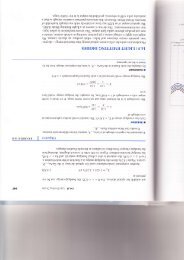
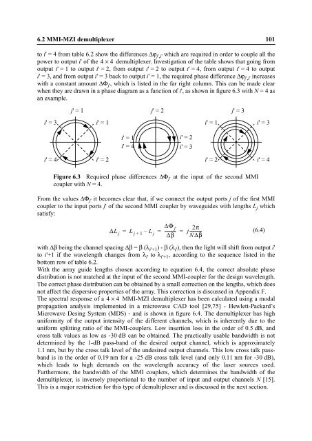
6.2 MMI-MZI demultiplexer 101<br />
to i' = 4 from table 6.2 show the differences Δϕj',i' which are required in order to couple all the<br />
power to output i' of the 4 × 4 demultiplexer. Investigation of the table shows that going from<br />
output i' = 1 to output i' = 2, from output i' = 2 to output i' = 4, from output i' = 4 to output<br />
i' = 3, and from output i' = 3 back to output i' = 1, the required phase difference Δϕj',i' increases<br />
with a constant amount ΔΦj' , which is listed in the far right column. This can be made clear<br />
when they are drawn in a phase diagram as a function of i', as shown in figure 6.3 with N = 4 as<br />
an example.<br />
i' = 3<br />
i' = 4<br />
j' = 1<br />
i' = 1<br />
i' = 2<br />
j' = 2<br />
i' = 1 i' = 2<br />
i' = 4<br />
i' = 3<br />
i' = 1<br />
i' = 2<br />
j' = 3<br />
Figure 6.3 Required phase differences ΔΦ j' at the input of the second MMI<br />
coupler with N = 4.<br />
i' = 3<br />
i' = 4<br />
From the values ΔΦ j' it becomes clear that, if we connect the output ports j of the first MMI<br />
coupler to the input ports j' of the second MMI coupler by waveguides with lengths L j which<br />
satisfy:<br />
ΔL j L j + 1 – L j ---------- j<br />
Δβ<br />
2π<br />
= = = -----------<br />
(6.4)<br />
NΔβ<br />
with Δβ being the channel spacing Δβ = β (λi'+1 ) - β (λi' ), then the light will shift from output i'<br />
to i'+1 if the <strong>wavelength</strong> changes from λi' to λi'+1 , according to the sequence listed in the<br />
bottom row of table 6.2.<br />
With the array guide lengths chosen according to equation 6.4, the correct absolute phase<br />
distribution is not matched at the input of the second MMI-coupler for the design <strong>wavelength</strong>.<br />
The correct phase distribution can be obtained by a small correction on the lengths, which does<br />
not affect the dispersive properties of the array. This correction is discussed in Appendix F.<br />
ΔΦ j'<br />
The spectral response of a 4 ×<br />
4 MMI-MZI demultiplexer has been calculated using a modal<br />
propagation analysis implemented in a microwave CAD tool [29,75] - Hewlett-Packard’s<br />
Microwave Desing System (MDS) - and is shown in figure 6.4. The demultiplexer has high<br />
uniformity of the output intensity of the different channels, which is inherently due to the<br />
uniform splitting ratio of the MMI-couplers. Low insertion loss in the order of 0.5 dB, and<br />
cross talk values as low as -30 dB can be obtained. The practically usable bandwidth is not<br />
determined by the 1-dB pass-band of the desired output channel, which is approximately<br />
1.1 nm, but by the cross talk level of the undesired output channels. This low cross talk passband<br />
is in the order of 0.19 nm for a -25 dB cross talk level (and only 0.11 nm for -30 dB),<br />
which leads to high demands on the <strong>wavelength</strong> accuracy of the laser sources used.<br />
Furthermore, the bandwidth of the MMI couplers, which determines the bandwidth of the<br />
demultiplexer, is inversely proportional to the number of input and output channels N [15].<br />
This is a major restriction for this type of demultiplexer and is discussed in the next section.