InP-based polarisation independent wavelength demultiplexers
InP-based polarisation independent wavelength demultiplexers
InP-based polarisation independent wavelength demultiplexers

Create successful ePaper yourself
Turn your PDF publications into a flip-book with our unique Google optimized e-Paper software.
6.2 MMI-MZI demultiplexer 109<br />
± 15 nm in order to maintain a cross talk level of less than -30 dB, whereas the guiding layer<br />
thickness has to be controlled within 5 nm for the same cross talk level.<br />
Waveguide loss tolerance<br />
In addition to these production deviations, waveguide losses may also have an impact on the<br />
performance due to the different lengths of the array arms. The losses will vary from one array<br />
guide to another, leading to a non-uniform intensity distribution at the input of the second MMI<br />
coupler. This will especially be the case if the required path length differences are obtained by<br />
different numbers of curved waveguide sections in the array guides, as in the structure of figure<br />
6.5b. The imaging in the second MMI coupler is not performed properly and therefore power is<br />
not only coupled to the desired output, but also to undesired outputs, leading to unwanted high<br />
cross talk values.<br />
To analyse this effect, the phase transfer in the second MMI-coupler will be considered, from<br />
which it is found that for one particular output all contributions add up coherently, leading to a<br />
proper image. For all other outputs each phase transfer term appears to have one counterphase<br />
term, leading to extinction of the fields. If these terms have different amplitudes due to<br />
attenuation in the demultiplexer, the extinction factor is reduced, i.e. the cross talk increases.<br />
From this analysis the sensitivity to loss variations in the different array guides, which leads to<br />
power imbalance at the input of the second MMI-coupler, can be calculated as follows and<br />
considering the configuration of figure 6.2. It should be noted that the splitting ratio of the<br />
MMI couplers is assumed to be uniform; the MMI couplers do not necessarily need to be<br />
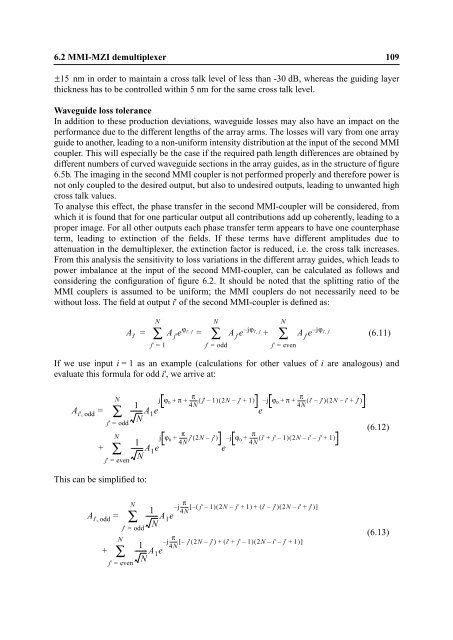
without loss. The field at output i' of the second MMI-coupler is defined as:<br />
A i'<br />
If we use input i = 1 as an example (calculations for other values of i are analogous) and<br />
evaluate this formula for odd i', we arrive at:<br />
Ai', odd<br />
=<br />
+<br />
j' = odd<br />
This can be simplified to:<br />
Ai', odd<br />
N<br />
∑<br />
N<br />
∑<br />
j' = even<br />
+<br />
=<br />
N<br />
∑<br />
N<br />
∑<br />
N<br />
∑<br />
– i', j'<br />
A j'e ϕi' j'<br />
A j'e jϕ – = =<br />
+<br />
i', j' (6.11)<br />
j' = 1<br />
1<br />
------- A1e N<br />
1<br />
------- A1e N<br />
N<br />
∑<br />
j' = odd<br />
j' = even<br />
, A j' e jϕ<br />
j' = odd<br />
π<br />
j ϕ0 + π + ------- ( j' – 1)<br />
( 2N – j' + 1)<br />
4N<br />
π<br />
j ϕ0 + ------- j'( 2N – j')<br />
4N<br />
1<br />
------- A1e N<br />
1<br />
------- A1e N<br />
e<br />
e<br />
N<br />
∑<br />
j' = even<br />
π<br />
– j ϕ0 + π + ------- ( i' – j')<br />
( 2N – i' + j')<br />
4N<br />
π<br />
– j ϕ0 + ------- ( i' + j' – 1)<br />
( 2N – i' – j' + 1)<br />
4N<br />
j π<br />
– ------- [ – ( j' – 1)<br />
( 2N – j' + 1)<br />
+ ( i' – j')<br />
( 2N – i' + j')<br />
]<br />
4N<br />
j π<br />
– ------- [ – j'( 2N – j')<br />
+ ( i' + j' – 1)<br />
( 2N – i' – j' + 1)<br />
]<br />
4N<br />
(6.12)<br />
(6.13)