Untitled - Sciencemadness Dot Org
Untitled - Sciencemadness Dot Org
Untitled - Sciencemadness Dot Org

You also want an ePaper? Increase the reach of your titles
YUMPU automatically turns print PDFs into web optimized ePapers that Google loves.
LOS ALAMOS SERIES ON<br />
DYNAMIC MATERIAL PROPERTIES<br />
LOS ALAMOS DATA CENTER<br />
FOR DYNAMIC MATERIAL PROPERTIES<br />
TECHNICAL COMMITTEE<br />
Charles L. Mader<br />
Terry R. Gibbs<br />
Charles E. Morris<br />
Stanley P. Marsh<br />
Alphonse Popolato<br />
Martha S. Hoyt<br />
Kasha V. Thayer<br />
Sharon L. Crane<br />
John F. Barnes<br />
Richard D. Dick<br />
John W. Hopson, Jr.<br />
James N. Johnson<br />
Elisabeth Marshall<br />
Timothy R. Neal<br />
Suzanne W. Peterson<br />
Raymond N. Rogers<br />
John W. Taylor<br />
Melvin T. Thieme<br />
Jerry D. Wackerle<br />
John M. Walsh<br />
Program Manager<br />
Explosive Data Editor<br />
Shock Wave Profile Editor<br />
Equation of State Editor<br />
Explosive Data Editor<br />
Computer Applications Analyst<br />
Technical Editor<br />
Technical Editor<br />
. .<br />
111
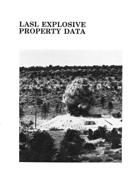
LASL EXPLOSIVE<br />
PROPERTY DATA<br />
Editors - Terry R. Gibbs<br />
Alphonse Popolato<br />
CONTRIBUTORS<br />
John F. Baytos<br />
Bobby G. Craig<br />
Arthur W. Campbell<br />
William E. Deal<br />
Jerry J. Dick<br />
Robert H. Dinegar<br />
Raymond P. Engelke<br />
Thomas E. Larson<br />
Elisabeth Marshall<br />
John B. Ramsay<br />
Raymond N. Rogers<br />
Diane Soran<br />
Manuel J. Urizar<br />
Jerry D. Wackerle<br />
UNIVERSITY OF CALIFORNIA PRESS<br />
Berkeley l Los Angeles l London
University of California Press<br />
Berkeley and Los Angeles, California<br />
University of California Press, Ltd.<br />
London, England<br />
Copyright @ 1980 by<br />
The Regents of the University of California<br />
ISBN o-520-040 12-O<br />
Series ISBN O-520-04007-4<br />
Library of Congress Catalog Card Number: 80-53635<br />
Printed in the United States of America<br />
123456789<br />
vi
CONTENTS<br />
PART I. EXPLOSIVES PROPERTIES BY EXPLOSIVES ................ 1<br />
Baratol ............................................................. 3<br />
Composition B ....................................................... 11<br />
Cyclotol ............................................................. 24<br />
DATB .............................................................. 34<br />
HMX ............................................................... 42<br />
Nitroguanidine ...................................................... 52<br />
Octal ............................................................... 61<br />
PBX 9011 ........................................................... 72<br />
PBX 9404 ........................................................... 84<br />
PBX 9407 ........................................................... 99<br />
PBX 9501 ........................................................... 109<br />
PBX 9502 ........................................................... 120<br />
PETN .............................................................. 130<br />
RDX ............................................................... 141<br />
TATB .............................................................. 152<br />
Tetryl ............................................................... 163<br />
TNT. .... :‘. ......................................................... 172<br />
XTX 8003 ........................................................... 188<br />
XTX 8004...........................................................19 6<br />
vii
PART II. EXPLOSIVES PROPERTIES BY PROPERTIES .............<br />
1. Chemical Properties ..........................................<br />
2. Thermal Properties ...........................................<br />
2.1 Heat Capacity Determination ..............................<br />
2.2 Thermal Conductivity .....................................<br />
2.3 Coefficient of Thermal Expansion ..........................<br />
2.4 Thermal Decomposition Kinetics ...........................<br />
2.5 Heats of Combustion and Formation ........................<br />
2.6 Differential Thermal Analysis and Pyrolysis Test ............<br />
2.7 Time-to-Explosion Test ....................................<br />
3. Detonation Properties .........................................<br />
3.1 Detonation Velocity and Diameter Effect. ...................<br />
3.2 Cylinder Test Performance .................................<br />
3.3 Detonation Pressure Determined from Initial<br />
Free-Surface Velocity ......................................<br />
3.4 Plate Dent Test ...........................................<br />
3.5 Detonation Failure Thickness ..............................<br />
4. Shock Initiation Properties ....................................<br />
4.1Wedge Test Data .........................................<br />
4.2 Small- and Large-Scale Gap Tests ..........................<br />
203<br />
204<br />
216<br />
216<br />
217<br />
218<br />
219<br />
221<br />
223<br />
231<br />
234<br />
234<br />
249<br />
258<br />
280<br />
289<br />
291<br />
293<br />
425<br />
4.3 Minimum Primary Charge ................................. 433<br />
4.4 Rifle Bullet Tests ......................................... 434<br />
4.5 Miscellaneous Tests ....................................... 440<br />
5. Sensitivity Tests ............................................. 446<br />
5.1 Drop Weight Impact Test .................................. 446<br />
5.2Skid Test ................................................. 454<br />
5.3 Large-Scale Drop Test or Spigot Test ....................... 458<br />
5.4 Spark Sensitivity .......................................... 460<br />
GLOSSARY ........................................................ 462<br />
AUTHORINDEX ................................................... 466<br />
SUBJECT INDEX .................................................. 468<br />
...<br />
F 111
PREFACE<br />
This volume of the Los Alamos Series on Dynamic Materials Properties is<br />
designed to provide a single source of reliable data on high explosives in use or<br />
formerly used at the Los Alamos National Scientific Laboratory (LASL). These are<br />
the best LASL data available and, as revisions are made, new or better data will be<br />
added.<br />
The volume is divided into two major parts for the user’s convenience. Part I pre-<br />
sents in one place the properties of explosives by explosive and summarizes all the<br />
property data and the results of various tests generally used to characterize ex-<br />
plosives. It covers only pure explosives and explosive formulations that have been<br />
well characterized. However, for many of these materials there are some properties<br />
or test results that have not been determined and in those cases the section normal-<br />
ly used to list the property or test result has been omitted. Part 11,presents the<br />
properties of explosives by property or method of determination It covers many<br />
more materials, often those for which only one property has been determined. Part<br />
II permits ready comparison of explosives and, for a number of properties, contains<br />
detailed data that permit use of other data reduction methods, such as the user’s<br />
own fitting techniques.<br />
Because many explosives properties depend upon the exact details of charge<br />
preparation, and their determination depends upon the exact details of the testing<br />
procedures, many of the test procedures used in gathering these data are described.<br />
References on the test procedures and data are cited where possible; however, much<br />
of the data has been taken from unpublished internal LASL reports. If more than<br />
one group of data or conflicting data were available, we selected the most credible.<br />
Also, because almost all of these explosives are heterogeneous polycrystalline<br />
materials, some of their properties, especially initiation by strong shocks, depend<br />
upon such factors as charge density, the particle size distribution of the crystals,<br />
and the degree of crystal perfection. Therefore, Part II includes detailed descrip-<br />
tions of the test explosives wherever possible.<br />
In Part I the explosives are discussed alphabetically and the various plastic-<br />
bonded explosives, PBXs, and extrudable explosives, XTXs, are discussed in<br />
numerical order. Part II, because it covers many more explosives formulations,<br />
ix
treats pure explosives first, alphabetically; then castables; then plastic-bonded ex-<br />
plosives, alphabetically by major explosive constituent; and, finally, propellants.<br />
An explosives table gives the composition of each material covered in this volume,<br />
and a glossary defines acronyms and unusual terms.<br />
The authors gratefully acknowledge the help that was provided by Margaret M.<br />
Cox and Jeanne Stein in producing many of the graphics.<br />
X
PART I<br />
EXPLOSIVES PROPERTIES<br />
BY EXPLOSIVE
EXPLOSIVES PROPERTIES BY EXPLOSIVE<br />
1. Baratol . . . . . , . . . . . . . . . . . . . . . . . . . . . . . . . . . . . . . . . . . . . . . . . . . . . . . . . . . . . . 3<br />
2. Composition B . . . . . . . . . . . . ..*........*....*..*.........*............ 11<br />
3. Cyclotol . . . , . . . . . * . * .I........................................,..... 24<br />
4. DATB . . . . . . . ..I................................................... 34<br />
5. HMX . . . . . . ..*...*...**.*........*....** ..*........*....*....,..... 42<br />
6. Nitroguanidine ,.................................................... 52<br />
7. Octal ,....,...,....,......................,........................ 61<br />
8. PBX 9011 . . . . . . . . . . . . . . . . . . . . . . . . . . . . . . . . . . . . . . . . . . . . . . . . . . . . . . . . . . 72<br />
9. PBX 9404 . , . . . . . . . , . . . ...*........*.............................**. 84<br />
10. PBX 9407 , . . . . . , . ,......,........,...,...,,........................ 99<br />
11. PBX 9501 . , . . . . . . . . . . . . . . . . . . . . ..I....... ,.*.............*....*.... 109<br />
12.PBX 9502 . . . . . . . . . . . ..s............ . . . . . . . . . . . . . . . . . . . . . . . . . . . . . . . . 120<br />
13. PETN . . . . . . . . . . . . . . . . . . . . . . . . . . . . . . . . . . . . . . . . . . . . . . ..I............ 130<br />
14.RDX . . . . . . . . . . . . . . . . . . . . . . . . . . . . . . . ..,........,....L.......,...... 141<br />
15. TATB . . . . . . . . . . . . . . . . . . . . . . . . . . . ..*...*......*.................... 152<br />
16. Tetryl............................... . . . . . . ..*.......*....*......... 163<br />
17. TNT. . , . . . , . . . . . . . . . . . . . . . . . . . . . . . . . . . . . . . . . . . . . . . . . . . . . . . . . . . . . . . . 172<br />
18. XTX 8003 . . . . . . + . . . . . . . . . . . . . . . . . . . . . . . . . ..*.*...*.*...*........... 188<br />
19. XTX 8004.. . . . . . . . . . . . . . . . . . . . . . . . . . . . . . . . . . . . . . . . . . . . . . . . . . . . . . . . . 196
BARATOL<br />
1. GENERAL PROPERTIES<br />
1.1 Chemical and Physical Description. Baratol, a mixture of barium nitrate,<br />
Ba(NO,),, and TNT, C,HsNBOB, is off-white to gray.<br />
1.2 Common Use. During World War II, the British developed baratols that con-<br />
tained about 20 wt% barium nitrate to replace TNT. The United States used<br />
baratols that contained slightly more barium nitrate in depth charges and other<br />
limited munitions. Baratols that contain up to 76 wt% barium nitrate are now used<br />
as the low detonation velocity explosive in waveshaping devices such as plane-wave<br />
lenses.<br />
1.3 Toxicity.’ Barium nitrate can irritate skin and mucous membranes.<br />
2. MANUFACTURE AND PROCUREMENT<br />
2.1 Manufacture. Finely ground barium nitrate is added to molten TNT to form<br />
a castable slurry. To lower the slurry viscosity, which increases with the percentage<br />
of barium nitrate, about 0.1 wt% of nitrocellulose (11.8-12.2 wt% nitrogen, 18-25<br />
centipoise) is added to the TNT before the addition of the barium nitrate. After the<br />
barium nitrate is added, just before vacuum is applied to the’melt, 0.05-0.1 wt% of<br />
either decylgallophenone or stearoxyacetic acid is added to prevent cracking.<br />
Vacuum is applied to the melt just before casting to remove dissolved and occluded<br />
gas and to provide higher, more uniform density. Carefully controlled cooling of the<br />
casting also promotes uniform density and composition.<br />
2.2 Procurement. There are no purchase specifications for baratol. It is<br />
produced to the user’s specific requirements at ordnance plants that have TNT-<br />
casting facilities.<br />
3<br />
’
BARATOL<br />
2.3 Shipping.2 Baratol is shipped as a Class A explosive, as defined by the Code<br />
of Federal Regulations.<br />
2.4 Storage.8 Baratol is stored in Compatibility Group D, Storage Class 1.1, as<br />
required by US Army Materiel Command regulation.<br />
3. CHEMICAL PROPERTIES<br />
3.1 Composition. Unless otherwise specified, the properties given are for the fol-<br />
lowing composition.<br />
4<br />
Constituent Weight Percent<br />
Barium nitrate<br />
TNT<br />
3.2 Molecular Weight.<br />
Constituent Structure<br />
--<br />
76.0<br />
2410<br />
Volume Percent<br />
62.8<br />
37.2<br />
Molecular Weight<br />
Barium nitrate 261.38<br />
TNT<br />
O2N<br />
/ I<br />
NO,<br />
GH,N,O,<br />
3.3 Solubility. Barium nitrate solubility in water is given.<br />
Temperature<br />
(“Cl<br />
NO2<br />
227.13<br />
Solubility<br />
(g/100 ml of solvent)<br />
20 8.7
4. PHYSICAL PROPERTIES<br />
4.2 Density.<br />
4.3 Infrared Spectrum. See Fig. 1..<br />
5. THERMAL PROPERTIES<br />
5.1 Phase Changes.<br />
Type<br />
Solid-to-liquid<br />
5.3 Heat Capacity.<br />
Density<br />
(g/cm”)<br />
Theoretical 2.634<br />
Vacuum cast 2.60-2.62<br />
Heat Capacity<br />
at Constant Pressure<br />
(Cal/g-“C)<br />
0.192<br />
WAVELENGTH (/un)<br />
WAVE NUMBER (I/cm)<br />
Temperature<br />
(“(3<br />
79-80<br />
Temperature<br />
Range<br />
(“C)<br />
18 < T < 75<br />
Latent Heat<br />
b-J/g)<br />
6.3<br />
BARATOL<br />
Fig. 1. Infrared spectrum.
BARATOL<br />
6<br />
5.4 Thermal Conductivity.<br />
Conductivity<br />
(Cal/s-cm-%)<br />
11.84 X lo-”<br />
/’<br />
5.5 Coefficient of Thermal Expansion.<br />
Coefficient of Expansion<br />
(l/co)<br />
Temperature<br />
Range<br />
(“C)<br />
18 < T < 75<br />
Temperature<br />
Range<br />
CC)<br />
3.4 x 1O-6 + 2.8 x lo-’ T -40 < T < 60<br />
5.6 Heats of Combustion and Formation.4<br />
Constituent<br />
TNT<br />
B4NCMZ<br />
AH:<br />
(kcal/mole)<br />
5.8 Other Thermal Stability Test Results.<br />
Vacuum<br />
AH;<br />
(kcal/mole)<br />
-817.2<br />
-12.0<br />
--- -238.23<br />
Test Results<br />
DTA and pyrolysis<br />
0.1-0.4 ml/g of gas evolved<br />
after 48 h at 120°C<br />
See Fig. 2<br />
1<br />
i<br />
t<br />
”<br />
i
,-<br />
6. DETONATION PROPERTIES<br />
Fig. 2. Raratol DTA and pyrolysis test results.<br />
BARATOL<br />
6.1 Detonation Velocity. The composition of baratol cast to approximately 97%<br />
of its theoretical density affects its detonation velocity as follows.<br />
Effect of Composition<br />
Weight Percent Detonation Velocity<br />
WNO& (mm/b4<br />
70 5.12<br />
72 5.03<br />
74 4.95<br />
76 4.86<br />
7
BARATOL<br />
6.2 Detonation Pressure.<br />
Weight Percent Density<br />
WNOa), (g/cm*)<br />
Detonation<br />
Velocity<br />
(mdm)<br />
76 2:61 4.925 14<br />
6.4 Plate Dent Test Results.<br />
Charge<br />
Diameter<br />
(mm)<br />
41.3<br />
Density Dent Depth<br />
(g/cm”) (mm)<br />
2.61<br />
7. SHOCK INITIATION PROPERTIES<br />
7.1 Gap Test Results.<br />
3.21<br />
Pressure<br />
(GW<br />
Charge<br />
Height<br />
(mm)<br />
Weight Percent Density G,O LX<br />
Noah g/cm”) (mm) (mm)<br />
Large Scale<br />
76 2.597 27.3 0.20<br />
7.2 Wedge Test Results.<br />
Density<br />
k/ma)<br />
Small Scale<br />
No data because sample was below failure diameter.<br />
Distance, x*, and Time, t*,<br />
to Detonation<br />
(mm and rs)<br />
2.61 log P = (1.2&0.03)-(0.3OikO.03) log x*<br />
log P = (1.01%O.Ol)-(0.27f0.02) log t*,<br />
where P= pressure in gigapascals.<br />
203<br />
Pressure Range<br />
(GW<br />
6.9 < P < 11.8
7.3 Shock Hugoniots.6<br />
Density<br />
Shock Hugoniot<br />
Wcma) (mdd<br />
8. SENSITIVITY<br />
BARATOL<br />
Particle Velocity Range<br />
(mm/d<br />
2.611 U, = 2.40 + 1.66 U,, 0
BARATOL<br />
REFERENCES<br />
. .<br />
1. N. I. Sax, Dangerous Properties of Industrial Materials, 4th Ed. (Van Nostrand<br />
Reinhold Company, New York, 1975).<br />
2. Code of Federal Regulations, 49, Transportation Parts 100-199, Rev. 12-1-76 (Of-<br />
fice of the Federal Register, General Services Administration, Washington, DC,<br />
1976).<br />
3. US Army Materiel Command, Regulation No. AMCR 385-100 (1977).<br />
4. Prince E. Rouse, Jr., Journal of Chemical and Engineering Data 21, 16-20 (1976).<br />
5. V. M. Boyle, R. L. Jameson, and M. Sultanoff, Proceedings-Fourth Sym-<br />
posium (International) on Detonation, White Oak, Maryland, October 12-15,<br />
1965 (Office of Naval Research, Department of the Navy, ACR-126, 1965), pp.<br />
241-247.<br />
10
COMPOSITION B<br />
1. GENERAL PROPERTIES<br />
1.1 Chemical and Physical Description. Composition B (Comp B), a mixture<br />
of 60 wt% RDX and 40 wt% TNT, with or without a wax desensitizer, is yellow-<br />
brown. Mixtures of RDX and TNT are generally called cyclotols in the United<br />
States, Hexolite in France, Fullpulver in Germany, Tritolite in Italy, Tritolita in<br />
Spain, and Hexotol in Sweden.<br />
Comp B desensitized with 1 wt% wax is available in grades A and B. Grade A is<br />
more fluid than Grade B when molten. Comp B-3 contains no desensitizer. It is<br />
more viscous than Grade A or B when molten because its median RDX particle<br />
diameter is smaller.<br />
1.2 Common Use. Comp B is used as the explosive fill in almost all types of ex-<br />
plosive ordnance.<br />
1.3 Toxicity.’ The toxicity of Comp B is like that of RDX and TNT.<br />
Workers who inhaled RDX dust for several months have become unconscious and<br />
have suffered loss of reflexes. The suggested maximum permissible airborne con-<br />
centration is 1.5 mg/ma.<br />
Inhaled TNT vapor or dust may irritate mucous membranes and cause sneezing,<br />
coughing, and sore throat. TNT may produce toxic hepatitis and aplastic anemia,<br />
and it yellows the exposed skin, hair, and nails of workers. Dermatitis, erythema,<br />
papules, and itchy eczema can be severe. Ingestion of l-2 g of TNT is estimated to<br />
be an acute fatal dose to humans. The suggested maximum permissible airborne<br />
dust concentration is 0.5 mg/ma.<br />
2. MANUFACTURE AND PROCUREMENT<br />
2.1 Manufacture. Comp B-type explosives, including cyclotols, are manufac-<br />
tured from TNT and water-wet RDX. The TNT is melted in a steam-jacketed ket-<br />
tle equipped with a stirrer and is brought to about 100°C. The wet RDX is added<br />
11
COMP B<br />
slowly. Heating and stirring are continued until most of the water is evaporated.<br />
The appropriate desensitizing wax or other additive is then thoroughly mixed with<br />
the other ingredients. After cooling to satisfactory fluidity, the Comp B is cast into<br />
strips or chips. The chips are shipped to an ordnance plant, remelted, and cast into<br />
ammunition or into desired shapes. During this melting, other additives may be in-<br />
troduced. To increase the density of cast charges, a vacuum may be applied to the<br />
molten Comp B before casting.<br />
2.2 Procurement. Comp B is purchased from the US Army Armament<br />
Readiness Command under military specification MIL-C-401C, dated May 15,<br />
1968, or, as Comp B-3, under MIL-C-45113, dated June 19, 1958.<br />
2.3 Shipping.2 Comp B is shipped as a Class A explosive.<br />
2.4 Storage.* Comp B is stored in Compatibility Group D, Storage Class 1.1.<br />
3. CHEMICAL PROPERTIES<br />
12<br />
3.1 Composition.<br />
Constituent<br />
RDX<br />
TNT<br />
Wax<br />
Comp B, Grades A and B Comp B-3 I<br />
Weight Volume Weight Volume<br />
Percent Percent Percent Percent<br />
59.5 56.9 60.0 57.8<br />
39.5 41.2 40.0 42.2<br />
1.0 1.9 0.0 0.0
3.2 Molecular Weight.<br />
Constituent Structure<br />
RDX H<br />
I2<br />
ON<br />
2 ,N/c\N,<br />
’<br />
I I<br />
9<br />
CH3<br />
OzN<br />
No2<br />
0<br />
IjO,<br />
C&NO,<br />
NO 2<br />
Wax CH,(CH,l, CH,<br />
Molecular<br />
Weight<br />
222.13<br />
227.13<br />
30.07 + (14.02),<br />
COMP B<br />
13
COMP B<br />
14<br />
3.3 Solubility.‘The solubility is that of the component’s RDX and TNT.<br />
Solvent<br />
Acetic acid<br />
99.6%<br />
71.0%<br />
Acetone<br />
Isoamyl alcohol<br />
Benzene<br />
Chlorobenzene<br />
Cyclohexanone<br />
Dimethylformamide<br />
Ethanol<br />
Methyl acetate<br />
Methylcyclohexanone<br />
Methyl ethyl ketone<br />
Toluene<br />
Trichloroethylene<br />
Water<br />
Solvent<br />
Acetone<br />
Benzene<br />
Butyl carbinol acetate<br />
Carbon disulfide<br />
Carbon tetrachloride<br />
Chlorobenzene<br />
Chloroform<br />
Diethyl ether<br />
Ethanol (95%)<br />
Ethylene chloride<br />
Hexane<br />
Methyl acetate<br />
Toluene<br />
Trichloroethylene<br />
Water<br />
-<br />
-<br />
Grams of RDX Dissolved/100 g of Solvent<br />
20°C 40°C 60°C<br />
0.46 0.56 1.22<br />
0.22 0.37 0.74<br />
6.81 10.34 __-.<br />
0.026 0.060 0.210<br />
0.045 0.085 0.195<br />
0.33 0.554 __-<br />
4.94 9.20 13.9<br />
___ 41.5 60.6<br />
0.12 0.24 0.58<br />
2.9 4.1 __-<br />
6.81 10.34 -_-<br />
3.23 ___ __-<br />
0.020 0.050 0.125<br />
0.20 0.24 __-<br />
0.005 0.0127 0.03<br />
Grams of TNT Dissolved/100 g of Solvent<br />
20°C 40°C 60°C<br />
109.0 228.0 600.0<br />
67.0 180.0 478.0<br />
24.0 ___ __-<br />
0.48 1.53 -_-<br />
0.65 1.75 6.90<br />
33.9 ___ __-<br />
19.0 66.0 302.<br />
3.29 ___ __-<br />
1.23 2.92 8.36<br />
18.7 .___ .__-<br />
0.16 ___ __-.<br />
72.1 ___ ___.<br />
55.0 130.0 367.0<br />
3.04 ___ ___<br />
0.0130 0.0285 0.0675
4. PHYSICAL PROPERTIES<br />
4.2 Density<br />
Theoretical<br />
Density<br />
Material (fibma)<br />
Comp B, Grades A and B 1.737<br />
Comp B-3 1.750<br />
4.3 Infrared Spectrum. See Fig. 1.<br />
5. THERMAL PROPERTIES<br />
5.1 Phase Change.<br />
% T<br />
2.5<br />
100<br />
80<br />
60<br />
40<br />
20<br />
0 LI<br />
4000 3000<br />
Type<br />
Density of Typical Casting<br />
k/cm”)<br />
COMP B<br />
Open Melt Vacuum Melt<br />
1.68-1.70 1.715-1.720<br />
_-_ 1.725-1.730<br />
Temperature Latent Heat<br />
(“0 (talk)<br />
Solid-to-slurry 79 14.1<br />
WAVELENGTH (urn)<br />
F<br />
WAVE NUMBER (I/cm)<br />
Fig. 1. Infrared spectrum.<br />
15
COMP B<br />
16<br />
5.3 Heat Capacity.<br />
Heat Capacity at Constant Pressure Temperature Range<br />
(Cal/g-“C) (“(3<br />
5.4 Thermal Conductivity.<br />
0.234 + 1.03 x D3 T<br />
Density<br />
Wcma)<br />
5.5 Coefficient of Thermal Expansion.<br />
Coefficient of Expansion<br />
(WC)<br />
Conductivity<br />
(Cal/s-cm-‘C)<br />
1.730 5.23 x lo-’<br />
7
5.8 Other Thermal Stability Test Results.<br />
Test Results<br />
Vacuum 0.2-0.6 ml/g of gas evolved<br />
after 48 h at 120°C<br />
DTA and pyrolysis<br />
See Fig. 2<br />
Critical temperature, Tm 214°C<br />
Charge radius, a<br />
3.0 mm<br />
6. DETONATION PROPERTIES<br />
6.1 Detonation Velocity.’<br />
COMP B<br />
Effect of Charge Radius<br />
Charge radius affects the detonation velocity of unconfined Grade A Comp B,<br />
cast to a density of 1.700 g/cm*, as follows.<br />
D(R) = 7.859[(1 - 2.84 X 10-“/R) - 5.51 X lo-VR(R - 1.94)],<br />
where D = detonation velocity in millimeters per microsecond<br />
and R = charge radius in millimeters.<br />
The experimentally determined failure diameter is 4.28 mm.<br />
Fig. 2. Comp R DTA and pyrolysis test results.<br />
17
COMP B<br />
18<br />
6.2 Detonation Pressure.’<br />
Grade A Comp B<br />
(Weight Percent RDX)<br />
Density<br />
WcmY<br />
Detonation Detonation<br />
Velocity Pressure<br />
(mm/d (GPa)<br />
64.0 1.713 8.018 29.22<br />
6.3 Cylinder Test Results.<br />
Detonation<br />
Density” Velocity<br />
k/cmS) (mm/d<br />
1.700b<br />
7.915<br />
1.715 I.911<br />
---------<br />
“Grade A Comp R.<br />
“Scaled from a -I-in.-diam shot.<br />
6.4 Plate Dent Test Results.e<br />
Charge<br />
Diameter<br />
(mm)<br />
Weight<br />
Percent<br />
RDX<br />
Cylinder Wall Velocity<br />
(mm/ps) at<br />
R-R, = 5 mm R-R,, = 19mm<br />
Density<br />
khm3)<br />
1.377 1.625<br />
1.378 1.628<br />
Dent<br />
Depth<br />
(mm)<br />
Charge<br />
Height<br />
(mm)<br />
41:3 6017 1.730 8:64 203<br />
41.3 64.0 1;714 8.47 203
7. SHOCK INITIATION PROPERTIES<br />
7.1 Gap Test Results.l”<br />
Type<br />
Density Weight Percent GO L<br />
k/cm* ) RDX (mm) (mm)<br />
Large Scale<br />
Comp R-3 1.727 60.0 50.34 0.81<br />
Grade A Comp R 1.710 64.0 45.69 0.45<br />
Grade A Comp R 1.714 64.0 45.18 0:08<br />
Small Scale<br />
Comp R-3 1.720 60.0 1.22 ___<br />
Grade A Comp R 1.710 __- 1.5 0.08<br />
7.2 Wedge Test Results.”<br />
Density<br />
(g/cm?<br />
Distance, x*, to Detonation<br />
(mm)<br />
Pressure Range*<br />
(kbar)<br />
1.72 2100 P-1.34, 40 < P < 100<br />
where P = pressure in kilobars.<br />
*Users should note that this is the only wedge data fit in this volume where<br />
pressure is in units of kilobars.<br />
.<br />
COMP B<br />
19
COMP B<br />
7.3 Shock Hugoniots.12J8<br />
Comp B-3 Density Shock Hugoniot<br />
k/cm? (mm/m)<br />
20<br />
1.680 u, = 2.71 + 1.86 u,,<br />
1.70 u, = 3.03 + 1.73 u,,<br />
7.4 Minimum Priming Charge.lO<br />
Density<br />
k/cmS)<br />
where U, = shock velocity<br />
and U, = particle velocity.<br />
W60<br />
(mg of XTX 8003)<br />
1.727” 245 0.070<br />
1.72E1~ 623 0.027<br />
------_--<br />
BComp R-3.<br />
bGrade A Comp R.<br />
7.5 Detonation Failure Thickness.‘O<br />
Density<br />
(g/cm?<br />
Failure Thickness<br />
(mm)<br />
Particle Velocity Range<br />
(mm/m)<br />
LO,<br />
(A log md<br />
LO,<br />
(mm)<br />
1.729” 0.785 0.086<br />
1.729” 0.881 0.297<br />
1.727* 0.805 0.081<br />
1.727” 0.813 0.051<br />
1.713b 1.42 0.07<br />
%omp B-:1<br />
Tirade A Camp R.<br />
0 < u, < 1.0<br />
c! < u, < 1.0
8. SENSITIVITY<br />
8.1 Drop Weight Impact Height<br />
Tool Type<br />
12<br />
12R<br />
8.2 Large-Scale Drop Test Height.<br />
8.3 Skid Test Results.<br />
Density 60<br />
k/cm3) (ft)<br />
1.725<br />
Density<br />
Impact<br />
Angle<br />
Wma) (degrees)<br />
1.727 15<br />
8.4 Susan Test Results.14<br />
85 Partial<br />
Target<br />
Surface<br />
Sand and epoxy<br />
HSO<br />
(cm)<br />
59<br />
109<br />
Reaction<br />
HSO<br />
w<br />
9.8<br />
Projectile Relative<br />
Impact Velocity Energy Release<br />
M/s) @Jo)<br />
600 0<br />
800<br />
5<br />
1000 20<br />
1200 30<br />
1400 38<br />
COMP B<br />
(Psi)<br />
< 0.5<br />
21
COMP B<br />
9. MECHANICAL PROPERTIES<br />
22<br />
9.2 Tensile Strength and Modulus.<br />
Ultimate Tensile Strength<br />
(psi)<br />
135-150<br />
9.3 Compressive Strength and Modulus.<br />
Temperature<br />
(“C)<br />
Ultimate<br />
Compressive Strength<br />
(Psi)<br />
CompressiveModulus<br />
(psi x 10-O)<br />
50 1400 rt96 0.63 f 0.1<br />
0 1860 f 200 2.40 f 0.3<br />
-40 2150f 280 2.50 f 0.2
REFERENCES<br />
1. C. R. Buck and S. E. Wilson, Jr., US Army report USEHA-32-049 (1975).<br />
COMP B<br />
2. Code of Federal Regulations, 49, Transportation Parts 100-199, Rev. 12-1-76<br />
(Office of the Federal Register, General Services Administration, Washington,<br />
DC, 1976).<br />
3. US Army Materiel Command, Regulation No. AMCR 385-100 (1977).<br />
4. A. Seidell, Solubilities of <strong>Org</strong>anic Compounds, 3rd Ed., Vol. II, (D. Van<br />
Nostrand Co., Inc., New York, 1941).<br />
5. Prince E. Rouse, Jr., Journal of Chemical Engineering Data 21, 16-20 (1976).<br />
6. R. N. Rogers, Thermochimica Acta 11,131-139 (1975).<br />
7. A. W. Campbell and Ray Engelke, Proceedings-Sixth Symposium (Inter-<br />
national) on Detonation, Coronado, California, August 24-27, 1976 (Office of<br />
Naval Research, Department of the Navy, ACR-221,1976), pp. 642-652.<br />
8. W. E. Deal, Journal of Chemical Physics 27,796-800 (1957).<br />
9. L. C. Smith, Explosivstoffe 15, 106-130 (1967).<br />
10. Manuel J. Urizar, Suzanne W. Peterson, and Louis C. Smith, Los Alamos<br />
Scientific Laboratory report LA-7193-MS (April 1978).<br />
11. J. B. Ramsay and A. Popolato, Proceedings-Fourth Symposium (Inter-<br />
national) on Detonation, White Oak, Maryland, October 12-15, 1965 (Office of<br />
Naval Research, Department of the Navy, ACR-126,1965), pp. 233-238.<br />
12. N. L. Coleburn and T. P. Liddiard, Journal of Chemical Physics 44, 1929-1936<br />
(1966).<br />
13. V. M. Boyle, R. L. Jameson, and M. Sultanoff, Proceedings-Fourth Sym-<br />
posium (International) on Detonation, White Oak, Maryland, October 12-15,<br />
2965 (Office of Naval Research, Department of the Navy, ACR-126, 1965), pp.<br />
241-247.<br />
14. L. G. Green and G. D. Dorough, Proceedings-Fourth Symposium (Inter-<br />
national) on Detonation, White Oak, Maryland, October 12-15, 1965 (Office of<br />
Naval Research, Department of the Navy, ACR-126, 1965), pp. 477-486.<br />
23
CYCLOTOL<br />
1. GENERAL PROPERTIES<br />
1.1 Chemical and Physical Description. Cyclotol is the generic term for mix-<br />
tures of TNT and RDX. In the United States, the term is used for mixtures of 75<br />
wt% RDX and 25 wt% TNT (Type I) or 70 wt% RDX and 30 wt% TNT (Type II),<br />
also called Cyclotol 75/25 and Cyclotol 70/30. Neither mixture contains a desen-<br />
sitizer. To improve the flow of the molten form, a bimodal distribution of RDX<br />
crystals generally is used.<br />
1.2 Common Use. Cyclotol is generally used as an explosive fill in military ap-<br />
plications that require slightly more energy than Comp B can provide.<br />
1.3 T0xicity.l Cyclotol toxicity is like that of RDX and TNT.<br />
Workers who inhaled RDX dust for several months have become unconscious and<br />
have suffered loss of reflexes. The suggested maximum permissible airborne con-<br />
centration of RDX is 1.5 mg/ms.<br />
Inhaled TNT vapor or dust may irritate mucous membranes and cause sneezing,<br />
coughing, and sore throat. TNT may produce toxic hepatitis and aplastic anemia,<br />
and it yellows the exposed skin, hair, and nails of workers. Dermatitis, erythema,<br />
papules, and itchy eczema can be severe. Ingestion of 1-2 g of TNT is estimated to<br />
be an acute fatal dose to humans. The suggested maximum permissible airborne<br />
dust concentration is 0.5 mglm”.<br />
24
2. MANUFACTURE AND PROCUREMENT<br />
CYCLOTOL<br />
2.1 Manufacture. Cyclotols are manufactured from TNT and water-wet RDX.<br />
The TNT is melted in a steam-jacketed kettle equipped with a stirrer and is<br />
brought to about 100°C. The wet RDX is added slowly, and heating and stirring are<br />
continued until the water is evaporated. Upon cooling to satisfactory fluidity, the<br />
cyclotol is cast into strips or chips. The chips are shipped to an ordnance plant,<br />
remelted, and cast into ammunition or into desired shapes. During this melting,<br />
other additives may be introduced. To increase the density of cast charges, a<br />
vacuum may be applied to the molten cyclotol before casting.<br />
2.2 Procurement. Cyclotol is purchased from the US Army Armament<br />
Readiness Command under military specification MIL-C-13477A, dated March 31,<br />
1965.<br />
2.3 Shipping.* Cyclotol is shipped as a Class A explosive.<br />
2.4 Storage.a Cyclotol is stored in Compatibility Group D, Storage Class 1.1.<br />
3. CHEMICAL PROPERTIES<br />
3.1 Composition.<br />
Constituent<br />
‘Me 1<br />
Type II<br />
Weight ‘Volume Weight Volume<br />
Percent Percent Percent Percent<br />
RDX 75:o 73.2 70.0 68:O<br />
TNT 25.0 26.8 30:o 32.0<br />
25
CYCLOTOL<br />
26<br />
3.2 Molecular Weight.<br />
Constituent Structure Molecular Weight<br />
RDX<br />
t-12<br />
O*N, /Cl /No2<br />
N<br />
I “;<br />
H /c\N/c\<br />
2<br />
ho,<br />
C,H,N,O,<br />
H2<br />
222.13<br />
TNT 227.13<br />
3.3 Solubility.4 The solubility is that of the components, RDX and TNT.<br />
Solvent<br />
Acetic acid<br />
99.6%<br />
71.0%<br />
Acetone<br />
Benzene<br />
Chlorobenzene<br />
Cyclohexanone<br />
Dimethylformamide<br />
Ethanol<br />
Isoamyl alcohol<br />
Methyl acetate<br />
Methylcyclohexanone<br />
Methyl ethyl ketone<br />
Toluene<br />
Trichloroethylene<br />
Water<br />
Grams of RDX Dissolved/100 g of Solvent<br />
20°C 40°C 60°C<br />
0.46<br />
0.22<br />
6.81<br />
0.045<br />
0.33<br />
4.94<br />
-__<br />
0.12<br />
0.026<br />
2.9<br />
6.81<br />
3.23<br />
0.020<br />
0.20<br />
0.005<br />
0.56<br />
0.37<br />
10.34<br />
0.085<br />
0.554<br />
9.20<br />
41.5<br />
0.24<br />
0.060<br />
4.1<br />
10.34<br />
---<br />
0.050<br />
0.24<br />
0.0127<br />
1.22<br />
0.74<br />
___<br />
0.195<br />
___<br />
13.9<br />
60.6<br />
0.58<br />
0.210<br />
___<br />
___<br />
0.125<br />
___<br />
0.03
Grams of TNT Dissolved/100 g of Solvent<br />
-<br />
Solvent 20°C<br />
40” c 60°C<br />
Acetone 109.0<br />
Benzene 67.0<br />
Butyl carbinol acetate 24.0<br />
.Carbon disulfide 0.48<br />
Carbon tetrachloride 0.65<br />
Chlorobenzene 33.9<br />
Chloroform 19.0<br />
Diethyl ether 3.29<br />
Ethanol (95%) 1.23<br />
Ethylene chloride 18.7<br />
Hexane 0.16<br />
Methyl acetate 72.1<br />
Toluene 55.0<br />
Trichloroethylene 3.04<br />
Water 0.013:<br />
4. PHYSICAL PROPERTIES<br />
4.2 Density.<br />
-<br />
CYCLOTOL<br />
228.0 600.0<br />
180.0 478.0<br />
__- _--<br />
1.53 _--<br />
1.75 6.90<br />
___ ---<br />
66.0 302.0<br />
--- __-<br />
2.92 8.30<br />
___ ---<br />
___ __-<br />
___ ---<br />
130.0 367.0<br />
___ _--<br />
0.0285 0.0675<br />
Density of<br />
Theoretical<br />
Typical Casting (g/ems)<br />
Density Open Vacuum<br />
Material (g/cmY Melt Melt<br />
Cyclotol75125 1.776 --- 1.74-1.75<br />
Type II,<br />
Cyc10t0170/30 1.765 1.71-1.73 ___<br />
27
CYCLOTOL<br />
4.3 Infrared Spectrum. See Fig. 1.<br />
5. THERMAL PROPERTIES<br />
28<br />
5.1 Phase Changes.<br />
Latent<br />
W/g)<br />
Heat<br />
Type<br />
Temperature<br />
7w 75/25 70/30<br />
Solid-to-slurry 79 5.81 7.05<br />
5.4 Thermal Conductivity.<br />
Type<br />
Density Conductivity<br />
khm3)<br />
(eal/s-cm-%)<br />
75125 1.760 5.41 x,10-’<br />
5.6 Heats of Combustion and Formationn6<br />
% T<br />
AH”,<br />
Constituent (kcal/mole)<br />
TNT -817.2<br />
RDX -501.8<br />
WAVELENGTH (urn)<br />
WAVE NUMBER II/cm)<br />
AH:<br />
(kcal/mole)<br />
-12.0<br />
14.7<br />
Fig. 1. Infrared spectrum.
5.7 Thermal Decomposition Kinetics.6<br />
Decomposition energy<br />
Activation energy<br />
Pre-exponential factor<br />
TNT RDX<br />
300 Cal/g<br />
34.4 kcal/mole<br />
2.51 X lO”/s<br />
5.8 Other Thermal Stability Test Results.<br />
Test Results<br />
500 Cal/g<br />
47.1 kcal/mole<br />
2.02 x 10%<br />
Vacuum 0.4-0.5 ml/g of gas evolved<br />
after 48 h at 120°C<br />
DTA and.pyrolysis<br />
See Fig. 2<br />
Critical temperature, Tm 208°C<br />
Charge radius, a 3.5 mm<br />
6. DETONATION PROPERTIES<br />
6.1 Detonation Velocity.’<br />
CYCLOTOL<br />
Effect of Charge Radius<br />
Charge radius affects the detonation velocity of unconfined Cyclotol75/25 cast to<br />
a density of 1.740 g/cm8 as follows.<br />
D(R) = 8.210[(1 - 4.89 x 1O-2/R) - O.llWR(R - 2.4411,<br />
Fig. 2. Cyclotol 75/25 DTA and pyrolysis test results.<br />
29
CYCLOTOL<br />
where D = detonation velocity in millimeters per microsecond,<br />
and R = charge radius in millimeters.<br />
The experimentally determined failure diameter is 6.0 mm.<br />
6.2 Detonation Pressure.*<br />
Weight Percent Density<br />
RDX k/cm3)<br />
Detonation Detonation<br />
Velocity Pressure<br />
(mm/d (GPa)<br />
77.0 1.743 8.252 31.25<br />
6.4 Plate Dent Test Resu1ts.O (See Part II for additional data.)<br />
Charge Weight<br />
Diameter Percent<br />
(mm)<br />
RDX<br />
Density<br />
(g/cd<br />
Dent Charge<br />
Depth Height<br />
(mm) (mm)<br />
41.3 77 1.200 5.38 203<br />
41.3 77 1.743 9.24 203<br />
7. SHOCK INITIATION PROPERTIES<br />
30<br />
7.1 Gap Test Results.l”<br />
Density<br />
k/cmS)<br />
1.756<br />
1.757<br />
1.744<br />
1.750<br />
Weight Percent<br />
RDX<br />
Large Scale<br />
77.0<br />
76.1<br />
77.3<br />
77.9<br />
Small Scale<br />
42.85 0.23<br />
43.15 0.15<br />
44.93 0.08<br />
44.17 1.30<br />
1.737 -__ 0.38 0.05<br />
1~746 77 0.18 0.05<br />
1.752 77 0.34 0.06
7.3 Shock Hugoniot<br />
Density Shock Hugoniot Particle Velocity Range<br />
k/cm3) (mm/m) (mdd<br />
1.752 U, = 2.63 + 1.85 U, 0 < up < 1.0<br />
where U, = shock velocity<br />
and U, = particle velocity.<br />
7.4 Minimum Priming Charge.lo<br />
Density Weight Percent ’<br />
(g/cm9<br />
RDX<br />
1.749 75<br />
1.739 70<br />
7.5 Detonation Failure Thickness.‘O<br />
8. SENSITIVITY<br />
Density Weight Percent<br />
(g/cm”)<br />
RDX<br />
1.752 77<br />
8.1 Drop Weight Impact Height.<br />
Tool Type<br />
8.2 Large-Scale Drop Test Height.‘l<br />
CYCLOTOL<br />
W,O LO,<br />
(mg of XTX 8003) (* log mg)<br />
785 0.054<br />
898 0.024<br />
Failure Thickness<br />
(mm)<br />
60<br />
(cm)<br />
12 36<br />
12R 108<br />
1.51<br />
Density H.50<br />
(g/cm3 ) vt) Reaction<br />
1.750 >150 No events<br />
LO,<br />
(mm)<br />
0.11<br />
31
CYCLOTOL<br />
8.3 Skid Test Results.<br />
Density<br />
Wcma)<br />
Weight<br />
Percent<br />
RDX<br />
Impact<br />
Angle<br />
(degrees)<br />
Target<br />
Surface<br />
J&O<br />
(W<br />
-<br />
Overpressure<br />
(Psi)<br />
1.758 77 15 Sand and epoxy 4 < 1.0<br />
8.4 Susan Test Results.1z<br />
8.5 Spark Sensitivity.<br />
I<br />
Projectile<br />
Impact Velocity<br />
Ws)<br />
Relative<br />
Energy Release<br />
W)<br />
- 200 5<br />
500 25<br />
1000 50<br />
Lead Foil Occurrence of<br />
Thickness Sample Size Energy Explosion<br />
Electrode (mils) bg) (J) (So)<br />
Brass 3 27 0.38 23<br />
Brass 10 27 3.29 23<br />
’ 9. MECHANICAL PROPERTIES<br />
32<br />
9.3 Compressive Strength and Modulus.<br />
Temperature<br />
(“C)<br />
Ultimate<br />
Compressive Strength<br />
(psi)<br />
Compressive<br />
Modulus<br />
(psi x IO- “)<br />
50 650 f 150 0.74 rt 0.3<br />
0 856 41 200 2.39 f 0.3<br />
-40 993 l 354 1.47 * 0.06
REFERENCES<br />
CYCLOTOL<br />
1. C. R. Buck and S. E. Wilson, Jr., US Army report USEHA-32-049 (1975).<br />
2. Code of Federal Regulations, 49, Transportation Parts 100-199, Rev. 12-1-76<br />
(Office of the Federal Register, General Services Administration, Washington,<br />
DC, 1976).<br />
3. US Army Materiel Command, Regulation No. AMCR 385100 (1977).<br />
4. A. Seidell, Solubilities of <strong>Org</strong>anic Compounds, 3rd Ed., Vol. II (D. Van<br />
Nostrand Co., Inc., New York, 1941).<br />
5. Prince E. Rouse, Jr., Journal of Chemical and Engineering Data 21, 16-20<br />
(1976).<br />
6. R. N. Rogers, Thermochimica Acta 11,131-139 (1975).<br />
7. A. W. Campbell and Ray Engelke, Proceedings-Sixth Symposium (Inter-<br />
national) on Detonation, Coronado, California, August 24-27, 1976 (Office of<br />
Naval Research, Department of the Navy, ACR-221, 1976), pp. 642-652.<br />
8. W. E. Deal, Journal of Chemical Physics 27,796-800 (1957).<br />
9. L. C. Smith, Explosivstoffe l&106-130 (1967).<br />
10. Manuel J. Urizar, Suzanne W. Peterson, and Louis C. Smith, Los Alamos<br />
Scientific Laboratory report LA-7193-MS (April 1978).<br />
11. A. Popolato, Proceedings of the International Conference on Sensitivity and<br />
Hazards of Explosives, Ministry of Aviation, Waltham Abbey, Essex (October<br />
1963).<br />
12. L. Green, Lawrence Livermore Laboratory, private communication (1975).<br />
33
DATB<br />
1. GENERAL PROPERTIES<br />
1.1 Chemical and Physical Description. DATB (1,3-diamino-2,4,6-<br />
trinitrobenzene), C,H,N,OB, is a yellow crystalline solid.<br />
1.2 Common Use. DATB is a relatively insensitive, temperature-resistant high<br />
explosive of limited military application. To be used effectively, it must be coated<br />
with a plastic (plastic-bonded explosive) or be mixed with liquid ingredients.<br />
1.3 Toxicity. Industrial health data on DATB toxicity are virtually nil. Animal<br />
exposure indicated no immediate hazard even at 80°C. Although DATB is relative-<br />
ly safe, it is from a homologous group that has caused skin sensitivity, cancer, and<br />
internal physical damage.<br />
2. MANUFACTURE AND PROCUREMENT<br />
2.1 Manufacture. DATB is synthesized from m-nitroaniline in two steps. The<br />
nitroaniline is nitrated with mixed sulfuric and nitric acids to give tetranitroaniline,<br />
which is then aminated using ammonia in methanol. DATB is insoluble in<br />
methanol and precipitates as it is formed. It may be recrystallized from<br />
dimethylformamide or dimethylsulfoxide.<br />
34
DATB<br />
2.2 Procurement. There is no dedicated DOD facility for DATB manufacture. It<br />
can be procured, on special order, from a few US chemical companies that have<br />
facilities for synthesizing energetic materials.<br />
2.3 Shipping.l DATB is shipped as a Class A explosive.<br />
2.4 Storage.2DATB is stored dry in Compatibility Group D, Storage Class 1.1.<br />
3. CHEMICAL PROPERTIES<br />
3.1 Structural Formula.<br />
3.2 Molecular Weight. 243.14<br />
3.3 Solubility.<br />
Solvent<br />
Acetic anhydride<br />
y-Rutyrolactone<br />
Cyclohexanone<br />
Dimethylformamide<br />
Dimethylsulfoxide<br />
Formamide‘<br />
Nitromethane<br />
Sulfuric acid<br />
Grams Dissolved/100 g<br />
of Solvent<br />
40°C 60°C<br />
0.492 ___<br />
0.810 ___<br />
0.355 _--<br />
2.96 4.88<br />
4.56 8.15<br />
0.282 ___<br />
0.362 ___<br />
22.2 22.9<br />
35
DATB<br />
4. PHYSICAL PROPERTIES<br />
4.1 Crystal Structure. 8,4 Two crystalline polymorphs of DATB have been iden-<br />
tified. The cell parameters of Form I, stable to 217’C, and of Form II are given.<br />
4.2 Density.s*4<br />
Cell Parameters<br />
Unit cell edge length (ft)<br />
Angle P<br />
Molecules per unit cell<br />
Method of<br />
Determination State<br />
X-ray<br />
Direct measurement<br />
;<br />
C<br />
Solid 23<br />
Solid 23<br />
Form I Form II<br />
7.30 f 0.01 7.76<br />
5.20 f 0~01 9.04<br />
11.63 f 0.02 12.84<br />
95.90 f 0.3”<br />
2<br />
Temperature<br />
(CO)<br />
103.0<br />
4<br />
Density (g/ems)<br />
Form I<br />
1.838<br />
1.837<br />
Form II<br />
1.84<br />
1.815<br />
DATB powder can be pressed into pellets. No quantitative pressing data is<br />
available.<br />
36<br />
4.3 Infrared Spectrum. See Fig. 1.<br />
2.5 4<br />
WAVELENGTH (pm)<br />
6 8 14<br />
WAVE NUMBER I I/cm)<br />
Fig. 1. Infrared spectrum.
5. THERMAL PROPERTIES<br />
5.1 Phase Changes.8-6<br />
‘be<br />
Solid-to-solid<br />
Form I to Form II<br />
Solid-to-liquid<br />
Solid-to-gas<br />
Form I<br />
Temperature Latent Heat<br />
v-3<br />
(kcal/mole)<br />
217<br />
286<br />
___<br />
__-<br />
--_ 33.47”<br />
---------<br />
“Computed from vapor pressure data presented in Sec. 5.2.<br />
5.2 Vapor Pressure.6<br />
Temperature<br />
(“Cl<br />
A least squares fit to these data gives<br />
5.3 Heat Capacity.<br />
Vapor Pressure,<br />
(mm Hg X 10’)<br />
62.6 0.081<br />
78.2 0.879<br />
85.3 2.09-2.36<br />
97.6 9.12-9.80<br />
108.1 34<br />
log,, P(mm Hg) = 13.73 - 33 470/4.576 T(K)<br />
Heat Capacity at Constant Pressure<br />
(Cal/g-‘C)<br />
0.261 + 1.11 x 10⁻³T<br />
DATB<br />
37
DATB<br />
5.4 Thermal Conductivity,<br />
Conductivity<br />
(Cal/s-cm-%)<br />
6.19 x lo-”<br />
5.6 Heats of Combustion and Formatioh at 25”C6<br />
5.7 Thermal Decomposition Kinetics.7<br />
AH; AH;<br />
(kcal/mole) (kcal/mole)<br />
-711.5 -23.6<br />
Decomposition energy 300 Cal/g<br />
Activation energy 46.3 kcal/mole<br />
Pre-exponential factor 1.17 X 10¹⁶/s<br />
5.8 Other Thermal Stability Test Results.<br />
Vacuum<br />
DTA and pyrolysis<br />
Critical temperature, Tm<br />
Charge radius, a<br />
Density, p<br />
6. DETONATION PROPERTIES<br />
38<br />
6.1 Detonation Velocity.8,8<br />
Test Results<br />
O.l-0;3 ml/g of gas evolved<br />
after 48 hat 120°C<br />
See Fig. 2<br />
322 “C<br />
3.5 mm<br />
1.74 g/cm3<br />
Effect of Density<br />
The infinite-diameter detonation velocity as a function of density is given by<br />
D = 2.480 + 2.852 p. ,<br />
where D = detonation velocity in millimeters per microsecond<br />
and p,, = charge density in grams per cubic centimeter.
DATB<br />
The failure diameter of unconfined DATB pressed to a density of 1.816 g/cm” is<br />
approximately 5.3 mm.<br />
6.2 Detonation Pressure.<br />
Detonation<br />
Density Velocity<br />
(d--W b-/m)<br />
1.780 7:60<br />
7. SHOCK INITIATION PROPERTIES<br />
7.1 Gap Test Results.l”<br />
Density<br />
(g/cm”)<br />
0.81’<br />
1.705<br />
1.786<br />
GO<br />
(mm)<br />
Large Scale<br />
49.27<br />
45.36<br />
41.68<br />
Small Scale<br />
L<br />
(mm)<br />
Detonation<br />
Pressure<br />
(GPa)<br />
0.23<br />
0.08<br />
0.18<br />
1.801 0.36 0.10<br />
25.1<br />
r I I I I , I I I I , I, I , I 1 I<br />
I<br />
PYRoLYsls<br />
I I I<br />
ICO<br />
f I I<br />
200<br />
I,, I I<br />
x0<br />
I I I1<br />
TEMPEwxT”RE PC1<br />
Fig. 2. DATR DTA and pyrolysis test results.<br />
1<br />
39
DATB<br />
7.3 Shock Hugoniot.9<br />
Density<br />
k/cm”)<br />
1.780<br />
7.4 Minimum Priming Charge.<br />
Shock Hugoniot<br />
(mdw)<br />
u, = (2.449 f 0.043) + (1.892 * 0.058) u,,<br />
where U, = shock velocity<br />
and U, = particle velocity.<br />
Density WSO<br />
k/cm*)<br />
(mg of XTX 8003)<br />
1.783 57.1 0.108<br />
7.5 Detonation Failure Thickness.<br />
8. SENSITIVITY<br />
Density<br />
(g/cm*)<br />
Failure Thickness<br />
(mm)<br />
1.708 0.630 0.069<br />
1.724 0.732 0.145<br />
8.1 Drop Weight Impact Height.<br />
Tool Type<br />
H.50<br />
(4<br />
12 >320<br />
12l3 230<br />
L<br />
(k logmd<br />
L<br />
(mm)
REFERENCES<br />
DATB<br />
1. Code of Federal Regulations, 49, Transportation Parts 100-199, Rev. 12-1-76<br />
(Office of the Federal Register, General Services Administration, Washington,<br />
DC, 1976).<br />
2. US Army Materiel Command, Regulation No. AMCR-385-100 (1977).<br />
3. J. R. Holden, Acta Crystallographica 22,545-550 (1967).<br />
4. J. R. Holden, A. H. Rosen, and J. M. Rosen, Naval Ordnance Laboratory,<br />
private communication (March 1959).<br />
5. J. M. Rosen and C. Dickenson, Naval Ordnance Laboratory report NOLTR-69-<br />
67 (April 1969).<br />
6. Prince E. Rouse, Jr., Journal of Chemical and Engineering Data 21, 16-20<br />
(1976).<br />
7. R. N. Rogers, Thermochimica Acta 11,131-139 (1975).<br />
8. N. L. Coleburn, B. E. Drimmer, and T. P. Liddiard, Naval Ordnance<br />
Laboratory, private communication (October 1960).<br />
9. N. L. Coleburn and T. P. Liddiard, Jr., Journal of Chemical Physics 44, 1929-<br />
1936 (1966).<br />
10. Manuel J. Urizar, Suzanne W. Peterson, and Louis C. Smith, Los Alamos<br />
Scientific Laboratory report LA-7193-MS (April 1978).<br />
41
HMX*<br />
1. GENERAL PROPERTIES<br />
1.1 Chemical and Physical Description. HMX, an explosive similar to RDX,<br />
was a byproduct in the production of RDX by the process that W. E. Bachmann<br />
and J. E. Sheehan developed. It has a higher density and much higher melting<br />
point than RDX. It was named HMX for High Melting explosive.<br />
HMX, C,H,N,O,, is a colorless polycrystalline material. It is also known as’<br />
octahydro-1,3,5,7-tetranitro-1,3,5,7-tetrazocine, cyclotetramethylene- tetrani-<br />
tramine, and Octogen.<br />
1.2 Common Use. Because of its higher density, HMX has replaced RDX in ex-<br />
plosive applications for which energy and volume are important. It is used in<br />
castable TNT-based binary explosives called Octols; as the main ingredient in<br />
high-performance plastic-bonded explosives, and in high-performance solid<br />
propellants.<br />
1.3 Toxicity.’ The suggested maximum concentration of HMX in air is 1.5<br />
mg/ma.<br />
*Unless otherwise specified, the properties listed are for the 0 polymorph.<br />
42
2. MANUFACTURE AND PROCUREMENT<br />
HMX<br />
2.1 Manufacture. A modified Bachmann batch process is used to produce<br />
HMX. Solutions of hexamine in acetic acid and ammonium nitrate in nitric acid<br />
are added to a base of acetic acid, acetic anhydride, and paraformaldehyde. A first<br />
period of continuous addition is followed by 15 minutes of aging, and a second<br />
period of continuous addition is followed by 1 hour of aging. Then the reaction mix-<br />
ture is diluted with hot water and heated to boiling to destroy all linear compounds.<br />
Cooling, filtering, and water washing complete preparation of the product. The<br />
crude HMX is purified by recrystallization from acetone solution to give a final<br />
product that is up to 99% beta HMX.<br />
2.2 Procurement. HMX is purchased from the US Army Armament Readiness<br />
Command under Military Specification MIL-H-45448, Amendment 1, dated July<br />
15.1975.<br />
2.3 Shipping.2 HMX is shipped as a Class A explosive and must be shipped wet<br />
with not less than 10% water.<br />
2.4 Storage.* HMX may be stored dry in Compatibility Group A or wet in Com-<br />
patibility Group D. Either wet or dry, it is in Storage Class 1.1.<br />
3. CHEMICAL PROPERTIES<br />
3.1 Structural Formula.<br />
43
HMX<br />
3.2 Molecular Weight. 296.17<br />
3.3 Solubility.<br />
Grams Dissolved/100 g of Solvent<br />
Solvent 20°C 40°C 60” C<br />
Acetic acid<br />
Glacial<br />
70%<br />
Acetic anhydride<br />
Acetone<br />
Anhydrous<br />
70%<br />
Acetonitrile<br />
Cyclohexanone<br />
Dimethylformamide<br />
Dimethylsulfoxide<br />
4. PHYSICAL PROPERTIES<br />
0.037 0.044 0.090<br />
-__ 0.033 0.103<br />
-_- 1.29 1.94<br />
2.4 3.4 ___<br />
0.66 1.20 --_<br />
__- 3.07 4.34<br />
__- 5.91 7.17<br />
__- 6.1 11.1<br />
_-- 45.5 47.2<br />
4.1 Crystal Structure.4-6 The cell parameters of the four polymorphic forms of<br />
HMX are given.<br />
44<br />
Cell<br />
Parameters<br />
Unit cell edge length (A)<br />
Angle p<br />
;<br />
C<br />
Molecules per unit cell<br />
a<br />
23.89 15.14<br />
5.91<br />
---<br />
8<br />
P Y 6<br />
11.05 6.54 10.95<br />
7.93<br />
7.66 ___<br />
7.37 14.61 32.49<br />
102.8” 119.4” ___<br />
2 4 6
4.2 Density.’<br />
Method of<br />
Determination State a<br />
Density<br />
(g/cm”)<br />
P - Y<br />
6<br />
__<br />
X-ray Solid 1.838 1.902 1.78 1.786<br />
Direct measurement Solid 1.84 1.905 1.76 1.80<br />
HMX<br />
HMX cannot be consolidated into charges by conventional pressing. Obtaining<br />
large pieces of polycrystalline HMX requires solvent pressing techniques.<br />
4.3 Infrared Spectrum. See Fig. 1.<br />
4.4 Refractive Index.’ The refractive indices of the four polymorphs in sodium<br />
light are shown.<br />
Face a B<br />
HMX Polymorph<br />
Alpha 1.561-1.565 1.589<br />
Beta 1.562-1.566 1.594-1.595<br />
Gamma 1.720-1.740 1.730-1.773<br />
Epsilon<br />
Omega<br />
Double<br />
refraction<br />
2.5<br />
__-<br />
___<br />
Pas<br />
WAVELI ENGTH<br />
6<br />
li<br />
16OC<br />
I (pm)<br />
WAVE NUMBER (I/cm 1<br />
6<br />
___<br />
___<br />
Pas<br />
14<br />
Y 6<br />
1.537 _-_<br />
1.585 _-_<br />
1.666 __-<br />
___ 1.566<br />
_-_ 1.607<br />
Pas neg<br />
Fig. 1. Infrared spectrum.<br />
45
HMX<br />
5. THERMAL PROPERTIES<br />
46<br />
5.1 Phase Changes.6-8<br />
Latent Heat<br />
‘be<br />
Temperaturea<br />
w W/d (kcal/mole)<br />
Solid-to-solid<br />
Bba<br />
atoy<br />
ato6<br />
Solid-to-liquid<br />
a*<br />
;<br />
Solid-to-gas<br />
102-104<br />
Metastable<br />
160-164<br />
2.0 0.6<br />
--_ ___<br />
7.8 2.3<br />
256-257 _-_ --_<br />
246-247 50.0 17.0<br />
279-280 _-_ __-<br />
280-281 --_ ---<br />
--- 141.4 41.8gb<br />
---------<br />
“There is some controversy about the temperature stability ranges of the four HMX<br />
polymorphs. These data are from Ref. 8.<br />
Vomputed from the vapor pressure data presented in Sec. 5.2.<br />
5.2 Vapor Pressure.B<br />
A least squares fit to these data gives<br />
Temperature Vapor Pressure<br />
(“(2<br />
(mm Hg x 10’)<br />
97.6 0.032<br />
108.2 0.164<br />
115.6 0.385-0.419<br />
129.3 2.830-2.870<br />
log,, P(mm Hg) = 16.18 - 41 890/4.576 T(K) .<br />
r
5.3 Heat Capacity.<br />
5.4 Thermal Conductivity.l”<br />
Heat Capacity<br />
at Constant Pressure<br />
(Cal/g-“C)<br />
0.231 + 5.5 X 1O-4 T<br />
Conductivity<br />
(Cal/s-cm-“C)<br />
Temperature<br />
Range<br />
(“C)<br />
37 < T < 167<br />
Temperature<br />
(“C)<br />
1.2 x 10-a 25<br />
9.7 x 10-d 160<br />
5.6 Heats of Combustion and Formation at 25%k11<br />
AH; AH;<br />
kcal/mole kcal/mole<br />
-660.7 11.3<br />
5.7 Thermal Decomposition Kinetics.l*.<br />
Decomposition energy 500 Cal/g<br />
Activation energy 52.7 kcal/mole<br />
Pre-exponential factor 5 x 10lg/s<br />
5.8 Other Thermal Stability Test Results.<br />
Test Results<br />
Vacuum 0: l-O.4 ml/g of gas evolved<br />
after 48 h at 120°C<br />
DTA and pyrolysis See Fig. 2<br />
Critical temperature, Tm 253°C<br />
Charge radius, a 3.3 mm<br />
Density, p 1.81 g/cm*<br />
HMX<br />
47
HMX<br />
6. DETONATION PROPERTIES<br />
6.1 Detonation Velocity.la<br />
6.2 Detonation Pressure.ls<br />
Fig. 2. HMX DTA and pyrolysis test results.<br />
Density<br />
(dcmS)<br />
Density<br />
(g/cm”)<br />
Detonation<br />
Velocity *<br />
(mdfis)<br />
1.89 9.110<br />
“Because HMX is a high-density<br />
version of RDX, their detonation<br />
velocities should be identical if<br />
they are compared at the same<br />
density.<br />
Computed<br />
Detonation Pressure<br />
(GM<br />
1.900 39.5
6.3 Cylinder Test Results.‘”<br />
Density<br />
k/cmS)<br />
1.891<br />
7. SHOCK INITIATION<br />
7.1 Gap Test Results.<br />
7.2 Wedge Test Results.<br />
Density<br />
k/ems)<br />
Cylinder Wall Velocity<br />
(mm/m) at<br />
R-R,,= 5mm R-R,,= 19mm<br />
1.65 1.86<br />
GO<br />
(mm)<br />
Large Scale<br />
1.07 70.68<br />
Small Scale<br />
0.71<br />
1.20 8.53 0.05<br />
1.79 4.23 0.10<br />
1.83 4.04 0.13<br />
Density Distance, x*, to Detonation<br />
WcmS)<br />
(mm)<br />
1.891 log P = (1.18tO.O2)-(0.59kO.03) log x*,<br />
where P = pressure in gigapascals.<br />
Pressure Range<br />
(GPa)<br />
4.41 < P < 9.55<br />
HMX<br />
49
HMX<br />
7.3 Shock Hugoniots.”<br />
Density Shock Hugoniot<br />
(g/cm3 ) (rnd~s)<br />
1.903<br />
1.89<br />
U, = 2.74 + 2.6 Up,*<br />
u, = (2.901 3~ 0.407) + (2.058 zb 0.490) U,,<br />
where U, = shock velocity<br />
and U, = particle velocity.<br />
*Computed from isothermal compression data,<br />
U,, = 2.67 + 2.6 UPt,<br />
Particle<br />
Velocity<br />
Range (mm/ps)<br />
.-<br />
0.59 < u, < 1.04<br />
where the subscripts “st” and “pt” indicate the shock and particle velocities, respectively, at<br />
constant temperature.<br />
8. SENSITIVITY<br />
50<br />
8.1 Drop Weight Impact Height.<br />
8.5 Spark Sensitivity.<br />
Tool Type<br />
KX<br />
(cm)<br />
12 26<br />
12R 37<br />
Lead Foil Sample<br />
Thickness Size<br />
Electrode (mils) bg)<br />
Rrass 3 66.9<br />
Rrass 10 66.9<br />
Steel 1 75.0<br />
Steel 10 75.0<br />
Energy<br />
(J)<br />
Occurrence of<br />
Explosion<br />
W)<br />
0.2 50<br />
1.03 50<br />
0.12 50<br />
0.87 50
REFERENCES<br />
HMX<br />
1. Committee on Threshold Limit Values: Documentation of Threshold Limit<br />
VaEues, 3rd Ed. (American Conference of Governmental Industrial Hygienists,<br />
1014 Broadway, Cincinnati, Ohio, 1971).<br />
2. Code of Federal Regulations, 49, Transportation Parts 100-199, Rev. 12-1-76<br />
(Office of the Federal Register, General Services Administration, Washington,<br />
DC, 1976).<br />
3. US Army Materiel Command, Regulation No. AMCR-385100 (1977).<br />
4. H. H. Cady, A. C. Larson, and D. T. Cromer, Acta Crystallographica 16, 617-<br />
623 (1963).<br />
5. W. C. McCrone, Analytical Chemistry 22, 12251226 (1950).<br />
6. Anna S. Teetsov and W. C. McCrone, Microscope 15,13-29 (1965).<br />
7. W. E. Beatty and B. Gilbert, Explosives Research and Development Establish-<br />
ment report ERDE 7/R/59 (October 1959).<br />
8. Howard H. Cady and Louis C. ‘smith, Los Alamos Scientific Laboratory report<br />
LAMS-2652 (1961).<br />
9. J. M. Rosen and C. Dickenson, Naval Ordnance Laboratory report NOLTR-69-<br />
67 (April 1969).<br />
10. C. M. Tarver, Lawrence Livermore Laboratory report UCID-17272-78-4<br />
(September 1978).<br />
11. 0. H. Johnson, Naval Ordnance Laboratory report NAVORD-4371 (October<br />
1956).<br />
12. R. N. Rogers, Thermochimica Acta 11,131-139 (1975).<br />
13. C. L. Mader, Los Alamos Scientific Laboratory report LA-2900 (July 1963).<br />
14. J. W. Kury, H. C. Hornig, E. L. Lee, J. L. McDonnel, D. L. Ornellas, M. Finger,<br />
F. M. Strange, and M. L. Wilkins, Proceedings-Fourth Symposium (Inter-<br />
national) on Detonation, White Oak, Maryland, October 12-15, 1965 (Office of<br />
Naval Research, Department of the Navy, ACR-126,1965), pp. 3-12.<br />
15. Bart Olinger, Brad Roof, and Howard Cady, Symposium (International) on<br />
High Dynamic Pressures, Paris, France, August 1978, pp. 3-8 (1978).<br />
51
NITROGUANIDINE<br />
1. GENERAL PROPERTIES<br />
1.1 Chemical and Physical Description. Nitroguanidine (NQ), CH,N,02, is a<br />
colorless polycrystalline material, generally in the form of a low-density matted<br />
structure. It is also known as Picrite.<br />
1.2 Common Use. NQ is used extensively as an ingredient in gun propellants,<br />
because the combustion products of such propellants are less erosive than those of<br />
other propellants of equivalent energy.<br />
2. MANUFACTURE AND PROCUREMENT<br />
2.1 Manufacture.‘v2 The procedures used to produce NQ are the British aqueous<br />
fusion (BAF) and the urea/ammonium nitrate processes. The United States uses a<br />
modified BAF process. Calcium carbide is reacted with nitrogen to form calcium<br />
cyanamide. The calcium cyanamide is reacted with carbon dioxide and water to<br />
form cyanamide, This is reacted with ammonium nitrate to form guanidine nitrate<br />
(GUN). GUN is reacted with 40 wt% oleum to form nitroguanidine. Final purifica-<br />
tion of the NQ is by crystallization from water.<br />
2.2 Procurement, NQ is purchased from the US Army Armament Readiness<br />
Command under military specification MIL-N-494A, dated January 31,1964.<br />
52<br />
2.3 Shipping.a NQ is shipped dry as a Class A explosive.<br />
2.4 Storage.‘NQ is stored dry in Compatibility Group D, Storage Class 1.1.
3. CHEMICAL PROPERTIES<br />
3.1 Structural Formula.6*6<br />
3.2 Molecular Weight. 104.1<br />
3.3 Solubility.<br />
HzN \<br />
/ C=N-NO,<br />
“ZN<br />
Solvent 20°C<br />
Water<br />
Dimethyl sulfoxide<br />
Dimethyl formamide<br />
Methanol<br />
Methyl ethyl ketone<br />
Rutyl acetate<br />
n-octane<br />
4. PHYSICAL PROPERTIES<br />
Grams Dissolved/100 g of Solvent<br />
40°C 60°C<br />
0.36 0.75 1.6<br />
24 25 28<br />
14 -__ 20<br />
0.3 0.6 ___<br />
0.13 0.20 ___<br />
0.07 0.08 0.1<br />
0.003 0.008 ___<br />
4.1 Crystal Structure.7~8 Only one polymorph of NQ has been observed. The<br />
orthorhombic unit cell parameters are given.<br />
Cell Parameters<br />
Length of unit cell edge (A)<br />
t ,<br />
17.58<br />
24.84<br />
C 3.58<br />
Molecules per unit cell 161<br />
NQ<br />
53
NQ<br />
54<br />
4.2 Density.’<br />
Crystal<br />
Method of<br />
Determination State<br />
X-ray<br />
Direct measurement<br />
Solid<br />
___<br />
Pressed<br />
Temperature Density<br />
(“(2 k/cm”)<br />
-_- 1.78<br />
25 1.77<br />
NQ can be pressed to a density of 1.70 g/cma at a pressure of 20 000 psi.<br />
4.3 Infrared Spectrum. See Fig. 1.<br />
4.4 Refractive Index.’<br />
Refractive Index<br />
in 5893-A Light<br />
a 1.526<br />
P<br />
1.694<br />
Y<br />
1.81<br />
WAVELENGTH I urn)<br />
% Fig. 1. Infrared spectrum.<br />
WAVE NUMBER (I/cm)
5. THERMAL PROPERTIES<br />
5.1 Phase Change.<br />
,<br />
5.3 Heat Capacity.<br />
Material<br />
Type<br />
Temperature<br />
(“Cl<br />
Solid-to-liquid 245-250*<br />
--------- .<br />
“Melting is usually preceded by decomposi-<br />
tion, which is very rapid in the liquid<br />
phase.<br />
Heat Capacity at<br />
Constant Pressure<br />
W/g-T)<br />
Temperature Range<br />
PC)<br />
LBD NQ” 0.242 + 0:OOll T(“C) 37 < T < 167<br />
HBD NQb (3.269 + 0.0007 T( “C) 37 < T < 167<br />
“Low-bulk density, in accordance with material specif’ication MU,-N-494A.<br />
bHigh-bulk density NQ recrystallized f’rom water, median particle diameier -300 pm.<br />
5.4 Thermal Conductivity.<br />
Material<br />
Density Conductivity<br />
(s/cm*)<br />
(cal/cm-s-°C)<br />
Temperature Range<br />
(W<br />
LBD NQ 1.65 10.1 x 10⁻⁴ 25 < T < 50<br />
1.69 9.8 x,10-’ 25 < T < 50<br />
NQ<br />
55
NQ<br />
56<br />
5.6 Heats of Combustion and Formation at 25’XLe<br />
AH;<br />
(kcal/mole)<br />
-210.4<br />
5.7 Thermal Decomposition Kinetics.loJ1<br />
AH;<br />
(kcal/mole)<br />
-20.29<br />
Decomposition energy 500 Cal/g<br />
Activation energy 20.9 kcal/mole<br />
Pre-exponential factor 2.84 x lO’/s<br />
5.8 Other Thermal Stability Test Results.<br />
Source<br />
Ref. 10 Ref. 11<br />
Test Results<br />
___<br />
57.1 kcal/mole<br />
8.75 x 10²²/s<br />
Vacuum Gas evolved after 48 h<br />
at 120°C (ml/g)<br />
NQ per MIL-N-494A<br />
Water recrystallized HBD NQ<br />
DMF recrystallized HBD NQ<br />
DTA and pyrolysis<br />
Critical temperature, Tm<br />
Charge radius, a<br />
Density, p<br />
0.0-1.0<br />
1.4-3.6<br />
0.6-1.2<br />
See Fig. 2<br />
198°C<br />
3.9 mm<br />
1.63 g/cm3
1 1<br />
$’ r I,.<br />
1 L<br />
1 / / I II,, 1 , I,, I<br />
0 m zco 300<br />
TEMPER4T”RE (“Cl<br />
6. DETONATION PROPERTIES<br />
6.1 Detonation Velocity.12<br />
Fig. 2. NQ DTA and pyrolysis test results.<br />
_<br />
Effect of Density<br />
The effect of density on the infinite-diameter detonation velocity is given by<br />
D, = 1.44 + 4.015 p,, for 0.3 < p0 < 1.78,<br />
where D m = infinite-diameter detonation velocity in millimeters per microse-<br />
cond,<br />
and p. = density in grams per cubic centimeter.<br />
Failure Diameter<br />
The LBD NQ failure diameter as a function of charge density is shown.<br />
Charge Density<br />
(g/cm*)<br />
Charge Diameter<br />
6-1<br />
Detonates Fails<br />
1.0 25.4 __-<br />
1.21 15.9 14.3<br />
1.52 14.3 12.7<br />
m<br />
NQ<br />
57
NQ<br />
6.2 Detonation Pressure. There are no experimental data on NQ detonation<br />
pressure. However, there is one data point from a mixture of 95 wt% NQ and 5 wt%<br />
Estane. The results are as follows.<br />
Material<br />
95 wt% NQ/<br />
5 wt% Estane<br />
6.4 Plate Dent Test Results.<br />
Density<br />
k/cm?<br />
Detonation Detonation<br />
Velocity Pressure<br />
(mm/cLs) (GW<br />
1.704 8.28 26.8<br />
Charge Diameter Density Dent Depth Charge Height<br />
(mm) (g/cm*) (mm) (mm)<br />
12.7 0.25 0.56 76.2<br />
12.7 0.40 0.79 76.2<br />
7. SHOCK INITIATION PROPERTIES<br />
58<br />
7.1 Gap Test Results.<br />
Density Go L6<br />
k/cm”) (mm) (mm)<br />
Large Scale<br />
1.609 5.00 0.5
7.2 Wedge Test Results.<br />
Density<br />
khma)<br />
Distance, x*, and Time, t*,<br />
to Detonation<br />
(mm and ps)<br />
1.659 to log P = (1.44&0.07)-(0.15*0.08) logx”<br />
1.723’ log P = (1.32&0:03)-(0.15lO.07) log t*<br />
Pressure Range<br />
(GM<br />
13.35 < P < 26.28<br />
1.688b IogP = (1.51f0.02)-(0.26f0.03) logx* 21.2 < P < 27.1<br />
“N$ median particle diameter, 300 pm, as cubic crystals.<br />
bNQ as long needle crystals with a needle diameter of’ a Ikw micrometers.<br />
7.3 Shock Hugoniots.<br />
Density<br />
(dad)<br />
Shock Hugoniots<br />
(mdk4<br />
Particle Velocity Range<br />
hdps)<br />
1.659 to B U,=(3.544&0.524)+(1.459&0.276) U,, 1.337 < u,
NQ<br />
8. SENSITIVITY<br />
8.1 Drop Weight Impact Height.<br />
REFERENCES<br />
Tool Type<br />
H&O<br />
(cm)<br />
12 >320<br />
12B >320<br />
1. C. H. Nichols, Picatinny Arsenal Technical report PA-TR-4566 (May 1974).<br />
2. G. Cowan, US Army Armament Materiel Command, private communication<br />
(1977).<br />
3. Code of Federal Regulations, 49, Transportation Parts 100-199, Rev. 12-1-76<br />
(Office of the Federal Register, General Services Administration, Washington,<br />
DC, 1976).<br />
4. US Army Armament Materiel Command, Regulation No. AMCR 385-100<br />
(1977).<br />
5. W. D. Kumler and P. P. T. Sah, Journal of <strong>Org</strong>anic Chemistry 18, 669-675<br />
(1953).<br />
6. W. D. Kumler, Journal of the American Chemical Society 76,814-816 (1954).<br />
7. W. C. McCrone, Analytical Chemistry 23,205-206 (1951).<br />
8. J. Donohue and J. H. Bryden, Acta Crystallographica 8,314-316 (1955).<br />
9. L. Medard and M. T. Thomas, Memorial des Poudres 31,173-196 (1949).<br />
10. R. N. Rogers, Thermochimica Acta 11,131-139 (1975).<br />
11. J. L. Block, US Naval Ordnance Laboratory report NAVORD-2705 (January<br />
1953).<br />
12. D. Price and A. R. Clairmont, US Naval Ordnance Laboratory report NOLTR<br />
67-169 (February 1968).<br />
60
OCTOL<br />
1. GENERAL PROPERTIES<br />
1.1 Chemical and Physical Description. Octal is the generic term for mixtures<br />
of TNT and HMX. In the United States, the mixtures consist of 75 wt% HMX and<br />
25 wt% TNT (Type I) or 70 wt% HMX and 30 wt% TNT (Type II), also called Octal<br />
75/25 and Octal 70/30. Neither mixture contains a desensitizer. To improve the flow<br />
characteristics of the molten form, a bimodal distribution of HMX crystals general-<br />
ly is used.<br />
1.2 Common Use. Octal is often used as an explosive fill in military applications<br />
that require more energy than either Comp B or Type I Cyclotol can provide.<br />
1.3 Toxicity.l*a Octal toxicity is like that of HMX and TNT.<br />
The suggested maximum concentration of HMX in air is 1.5 mg/m”.<br />
Inhaled TNT vapor or dust may irritate mucous membranes and cause sneezing,<br />
coughing, and sore throat. TNT may produce toxic hepatitis and aplastic anemia.<br />
TNT yellows the exposed skin, hair, and nails of workers. Dermatitis, erythema,<br />
papules, and itchy eczema can be severe. Ingestion of 1-2 g of TNT is estimated to<br />
be an acute fatal dose to humans. The suggested maximum permissible airborne<br />
dust concentration is 0.5 mg/ma.<br />
2. MANUFACTURE AND PROCUREMENT<br />
2.1 Manufacture. Octols are manufactured from TNT and water-wet HMX.<br />
The TNT is melted in a steam-jacketed kettle equipped with a stirrer and brought<br />
to about 100°C. The wet HMX is added slowly, and stirring is continued until the<br />
water is evaporated. The slurry temperature is reduced until the viscosity is<br />
satisfactory for casting. The octal is cast onto a continuous belt, as strips or chips.<br />
61
OCTOL<br />
These are shipped to an ordnance plant. remelted. and cast into ammunition or into<br />
other desired shapes. During this melting, other additives may be introduced. To<br />
increase the density of the cast charges, a vacuum may be applied to the molten<br />
octal before casting.<br />
2.2 Procurement. Octal is purchased from the US Army Armament Command<br />
under military specification ML0455446A, dated September :30.1962.<br />
2.3 Shipping.’ Octal is shipped as a Class A explosive.<br />
2.4 Storage.’ Octal is stored in Compatibility Group D. Storage Class 1.1.<br />
3.CHEMICALPROPERTIE9<br />
3.1 C4mposidon.<br />
Constituent<br />
62<br />
Type1<br />
Weight Volume<br />
percent Percent<br />
Weight<br />
Percent<br />
Type II<br />
Volume<br />
Percent<br />
HMS 76 :2..3 70 66.5<br />
TNT 25 27.7 30 A3 1
3.2 Molecular Weight.<br />
Constituent Structure Molecular Weight<br />
HMX<br />
TNT<br />
O2V<br />
H2<br />
I<br />
N-C--N<br />
,NO2<br />
I 1<br />
c-n,<br />
H2S-C<br />
I 1<br />
/N--;:-NNN02<br />
O2N<br />
H2<br />
CH3<br />
k0,<br />
C,H,N,O,<br />
296.17<br />
227.13<br />
OCTOL<br />
63
64<br />
OCTOL<br />
3.3 Solubility.6 The solubility is that of the components, HMX and TNT.<br />
Solvent<br />
Acetic acid<br />
Glacial<br />
70%<br />
Acetic anhydride<br />
Acetone<br />
Anhydrous<br />
70%<br />
Acetonitrile<br />
Cyclohexanone<br />
Dimethylformamide<br />
Dimethylsulfoxide<br />
Solvent<br />
Acetone<br />
Benzene<br />
Butyl carbinol acetate<br />
Carbon disulfide<br />
Carbon tetrachloride<br />
Chlorobenzene<br />
Chloroform<br />
Diethyl ether<br />
Ethanol (95%)<br />
Ethylene chloride<br />
Hexane<br />
Methyl acetate<br />
Toluene<br />
Trichloroethylene<br />
Water<br />
Grams of HMX Dissolved/100 g of Solvent<br />
20°C 40°C 60°C<br />
0.037 0.044<br />
-__ 0.033<br />
--- 1.29<br />
2.4 3.4<br />
0.66 1.20<br />
___ 3.07<br />
___ 5.91<br />
___ 6.1<br />
__- 45.5<br />
0.090<br />
0.103<br />
1.94<br />
___<br />
4.34<br />
7.17<br />
11.1<br />
47.2<br />
Grams of TNT Dissolved/100 g Solvent<br />
20°C 40” c 60°C<br />
109.0 228.0 600.0<br />
67.0 180.0 478.0<br />
24.0 ___ _-_<br />
0.48 1.53 ___<br />
0.65 1.75 6.90<br />
33.9 ___ ___<br />
19.0 66.0 302.0<br />
3.29 ___ ___<br />
1.23 2.92 8.30<br />
18.7 ___ ___<br />
0.16 ___ ___<br />
72.1 ___ ___<br />
55.0 130.0 367.0<br />
3.04 -__ ___<br />
0.0130 0.0285 0.0675
4. PHYSICAL PROPERTIES<br />
4.2 Density.<br />
Material<br />
Theoretical<br />
Density<br />
(f&m*)<br />
Tw 1,<br />
Octal 75/25 1;835<br />
Type J&<br />
Octal 70/30 1.822<br />
4.3 Infrared Spectrum. See Fig. 1.<br />
WAVELENGTH L~rn)<br />
WAVE NUMBER (I/cm)<br />
Density of Typical Casting<br />
(f&ma)<br />
Open Melt Vacuum Melt<br />
1.800 1.810-1.825<br />
1.790 1.805-1.810<br />
OCTOL<br />
Fig. 1. Infrared spectrum.<br />
65
OCTOL<br />
5. THERMAL PROPERTIES<br />
66<br />
5.1 Phase Changes.<br />
5w<br />
Temperature<br />
m<br />
Latent Heat<br />
(Cal/g)<br />
75/25 70/30<br />
Solid-to-slurry 79 5.87 7.05<br />
5.6 Heats of Combustion and Formation.g<br />
Constituent<br />
AH:<br />
(kcal/mole)<br />
AH;<br />
(kcal/mole)<br />
TNT -817.2 -12.2<br />
HMX -660.7 11.3<br />
5.7 Thermal Decomposition Kinetics.’<br />
Decomposition energy<br />
Activation energy<br />
Pre-exponential factor<br />
, /<br />
TNT HMX<br />
300 Cal/g<br />
34.4 kcal/mnle<br />
2.5 x loll/s<br />
5.8 Other Thermal Stability Test Results.<br />
Test Results<br />
500 Cal/g<br />
52.7 kcal/mole<br />
5 x lO’S/s<br />
Vacuum 0.1-0.4 ml/g of gas evolved<br />
after 48 h at 120°C<br />
DTA and pyrolysis<br />
Critical temperature, Tm<br />
Charge radius, a<br />
Density, p<br />
See Fig. 2<br />
281°C<br />
3.7 mm<br />
1.70 g/cma
6. DETONATION PROPERTIES<br />
6.1 Detonation Velocity.B<br />
Fig. 2. Octal DTA and pyrolysis test results.<br />
OCTOL<br />
Effect of Charge Radius<br />
Charge radius affects the detonation velocity of unconfined Octal 77/23 cast to a<br />
density of 1.814 g/cm* as follows.<br />
D(R) = 8.481[(1 - 6.9 X lO+R) - (9.25 X 10⁻²)/R(R - 1.34)] ,<br />
where D = detonation velocity in millimeters per microsecond<br />
and R = charge radius in millimeters.<br />
The experimentally determined failure diameter is
OCTOL<br />
68<br />
6.4 Plate Dent Test Results.<br />
Charge Weight<br />
Diameter Percent<br />
(mm)<br />
HMX<br />
41.3 76.3<br />
41.3 76.4<br />
7. SHOCK INITIATION PROPERTIES<br />
7.1 dap Test Results.g<br />
Density<br />
WcmS)<br />
1.809<br />
1.802<br />
Dent<br />
Depth<br />
(mm)<br />
lo:06<br />
9.99<br />
Charge<br />
Height<br />
(mm)<br />
Weight Percent Density G&O L%<br />
HMX k/cm”) (mm) (mm)<br />
Large Scale<br />
76.0 1.822 49;45 0.2<br />
a 1.726 48.59 0.41<br />
a 1.795 43.56 0.46<br />
Small Scale<br />
76.0 1.803 0.71 0.08<br />
76.0 1.810 0.58 ---<br />
78.6 1.800b 0.56 0.06<br />
: 1.775 1.791 0.36 0.41 0;05 0.05<br />
---------<br />
“UK EDC-1 nominal 75 wt% HMX with some RDX.<br />
“With 1 wt% wax.<br />
‘UK EDC-1 cast in the United Kingdom.<br />
dUK EDC-1 vacuum cast in the United States.<br />
7.3 Shock Hugoniots.‘O /<br />
Density Weight Percent Shock Hugoniot Particle Velocity Range<br />
(g/cm? HMX (mm/m) (mm/b4<br />
-<br />
1.80 75 u, = 3.01+ 1.72u,, 0
7.4 Minimum Priming Charge.9<br />
Density Weight Percent<br />
k/cm* ) HMX<br />
1.818 75<br />
7.5 Detonation Failure Thickness.9<br />
Density Weight Percent<br />
(g/cm*)<br />
HMX<br />
1.791 75<br />
8. SENSITIVITY<br />
8.1 Drop Weight Impact Height.<br />
Tool Type<br />
8.2 Large-Scale Drop Test Height.”<br />
Density Weight Percent<br />
(g/cm*)<br />
HMX<br />
1.310 75<br />
1.805 758<br />
1.766 b<br />
---------<br />
“Octal 75/25 with 1 wt% wax.<br />
WK EDC-1 cast in the United Kingdom.<br />
W60<br />
(mg of XTX 8003)<br />
292<br />
Failure Thickness L*<br />
(mm) (mm)<br />
HE&<br />
(cm)<br />
12 38<br />
12l3 93<br />
1.43<br />
Reaction<br />
OCTOL<br />
L9,<br />
(A log mg)<br />
0.028<br />
45 Low-order partial<br />
-150 Low-order partial<br />
-110 Low-order partial<br />
0.21<br />
-<br />
69
OCTOL<br />
8.3 Skid Test Results.<br />
Weight<br />
Percent<br />
HMX<br />
1.810 75<br />
1.805 a<br />
__-------<br />
“Cast with 1 wt% wax.<br />
8.4 Susan Test Results.12<br />
8.5 Spark Sensitivity.<br />
Electrode<br />
Impact<br />
Angle<br />
(degrees)<br />
45<br />
45<br />
Target<br />
Surface<br />
Reaction<br />
Overpressure<br />
(Psi)<br />
Sand and epoxy -75 0.1<br />
Sand and epoxy > 150 ---<br />
Projectile Impact Velocity Relative Energy Release<br />
(ft/s) e/o)<br />
200 0<br />
.400 20<br />
1000 60<br />
Lead Foil Sample<br />
Thickness Size<br />
(mils) bg)<br />
Energy<br />
(J)<br />
Occurrence of<br />
Explosion<br />
(%)<br />
Rrass 3 29 0.82 17<br />
&ass 10 29 4.36 17<br />
9. MECHANICAL PROPERTIES<br />
9.3 Compressive Strength and Modulus.<br />
Temperature Density<br />
(“C) k/cm*)<br />
70<br />
Weight<br />
Percent<br />
HMX<br />
Ultimate Compressive<br />
Strength<br />
(Psi)<br />
Compressive<br />
Modulus<br />
(psi x 1O-5)<br />
Ambient 1:821-1.824 76 2000-2340 8.0 to 13.4
REFERENCES<br />
OCTOL<br />
1. Commitee on Threshold Limit Values, Documentation of Threshold Limit<br />
Values, 3rd Ed. (American Conference of Governmental Industrial Hygien-<br />
ists, 1014 Broadway, Cincinnati, Ohio, 1971).<br />
2. C. R. Buck and S. E. Wilson, Jr., US Army report USEHA-32-049 (1975).<br />
3. Code of Federal Regulations, 49, Transportation Parts 100-199, Rev. 12-1-76<br />
(Office of the Federal Register, General Services Administration, Washington,<br />
DC, 1976).<br />
4. US Army Materiel Command, Regulation No. AMCR 385-100 (1977).<br />
5. A. Seidell, Solubilities of <strong>Org</strong>anic Compounds, 3rd Ed., Vol II, (D. Van<br />
Nostrand Co., Inc., New York, 1941).<br />
6. Prince E. Rouse, Jr., Journal of Chemical and Engineering Data 21, 16-20<br />
(1976).<br />
7. R. N. Rogers, Thermochimica Acta 11, 131-139 (1975).<br />
8. A. W. Campbell and Ray Engelke, Proceedings-Sixth Symposium (Inter-<br />
national) on Detonation, Coronado, California, August 24-27, 1976 (Office of<br />
Naval Research, Department of the Navy, ACR-221,1976), pp. 642-652.<br />
9. Manuel J. Urizar, Suzanne W. Peterson, and Louis C. Smith, Los Alamos<br />
Scientific Laboratory report LA-7193-MS (April 1978).<br />
10. V. M. Boyle, R. L. Jameson, and M. Sultanoff, Proceedings-Fourth Sym-<br />
posium (International) on Detonation, White Oak, Maryland, October 12-15,<br />
1965 (Office of Naval Research, Department of the Navy, ACR-126, 1965), pp.<br />
241-247.<br />
11. A. Popolato, Proceedings of the International Conference on Sensitivity and<br />
Hazards of Explosives, Ministry of Aviation, Waltham Abbey, Essex (October<br />
1963).<br />
12. L. Green, Lawrence Livermore Laboratory, private communication (1975).<br />
71
PBX 9011<br />
1. GENERAL PROPERTIES<br />
1.1 Chemical and Physical Description. PBX 9011 is composed of HMX<br />
bonded with Estane 5703. The molding powder is off-white to light brown.<br />
1.2 Common Use. PBX 9011 is a high-performance explosive that is used in a<br />
variety of special applications in nuclear ordnance.<br />
1.3 Toxicity.’ Estane 5703 is not toxic. The suggested maximum concentration<br />
of HMX in air is 1.5 mg/ma.<br />
2. MANUFACTURE AND PROCUREMENT<br />
2.1 Manufacture. PBX-9011 molding powder is prepared by the water slurry<br />
process. An Estane lacquer is prepared in a water-immiscible solvent. This is added<br />
to a water slurry containing a bimodal distribution of HMX crystals. During solvent<br />
removal by distillation, the plastic uniformly coats and agglomerates the HMX<br />
crystals in the water phase. The process variables must be controlled closely to<br />
produce satisfactory agglomerates, composition, and bulk density.<br />
72
PBX 9011<br />
2.2 Procurement. PBX 9011 is purchased from the US Army Armament<br />
Readiness Command under LASL material specification 13Y-101030 Rev. B, dated<br />
January 9,1967.<br />
2.3 Shipping.2 PBX-9011 molding powder is shipped as a Class A explosive.<br />
2.4 Storage.a PBX 9011 is stored in Compatibility Group D, Storage Class 1.1.<br />
3. CHEMICAL PROPERTIES<br />
3.1 Composition.<br />
3.2 Molecular Weight.<br />
Constituent<br />
HMX<br />
Estane 5703<br />
Weight Volume<br />
Percent Percent<br />
90<br />
10<br />
84.9<br />
15.1<br />
Constituent Structure Molecular Weight<br />
HMX 296.17<br />
0 0 0<br />
Estane HO-(CH2)4-0 [~-O-(CH2)q-O]n--d;-(-$~-~-~-C- m 100.0<br />
H<br />
73
PBX 9011<br />
3.3 Solubility. The solubility is that of HMX.<br />
Acetic acid<br />
Glacial<br />
70%<br />
Acetic anhydride<br />
Acetone<br />
Anhydrous<br />
70%<br />
Acetonitrile<br />
Cyclohexanone<br />
Dimethylformamide<br />
Dimethylsulfoxide<br />
4. PHYSICAL PROPERTIES<br />
4.2 Density.<br />
Grams of HMX Dissolved/100 g of Solvent<br />
Solvent 20°C 40” c 60°C<br />
--_-<br />
0.037 0.044<br />
____ 0.033<br />
__-_ 1.29<br />
2.4 3.4<br />
0.66 1.20<br />
____ 3.07<br />
-.__ 5.91<br />
____ 6.1<br />
____ 45.5<br />
Theoretical Density of Typical<br />
Density Pressed Charges<br />
WcmY (f&m*)<br />
1.795 1;770<br />
0.090<br />
0.103<br />
1.94<br />
4.34<br />
7.17<br />
11.1<br />
47.2<br />
The following densities are obtained by vacuum pressing (residual pressure
4.3 Infrared Spectrum. See Fig. 1.<br />
5. THERMAL PROPERTIES<br />
5.1 Phase Changes.<br />
Type<br />
Temperature Latent Heat<br />
(“(3 Wig)<br />
P-to-b solid-to-solid<br />
in HMX 190 9.2<br />
5.3 Heat Capacity.<br />
5.4 Thermal Conductivity.<br />
Heat Capacity Temperature<br />
at Constant Pressure Range<br />
(Cal/g-“C) (“C)<br />
0.259 + 6.3 x lo-’ T<br />
Density Conductivity<br />
(g/cm”)<br />
(Cal/s-cm-W)<br />
WAVELENGTH (pm)<br />
1.772 9.08 x IO-’<br />
WAVE NUMBER (I/cm)<br />
17 < T < 167<br />
PBX 9011<br />
Fig. 1. Infrared spectrum.<br />
75
PBX 9011<br />
76<br />
5.5 Coefficient of Thermal Expansion.<br />
Density Coefficient of Expansion<br />
(s/cm*) (WC)<br />
1.752 22.2 x 1o-e<br />
5.6 Heats of Combustion and Formation.<br />
AH;<br />
Constituent (kcal/mole)<br />
HMX -660.7<br />
5.7 Thermal Decomposition Kinetics.4<br />
Property<br />
Temperature Range<br />
(“C)<br />
AH;<br />
(kcal/mole)<br />
25 < T < 74<br />
11.3<br />
Decomposition energy 500 Cal/g<br />
Activation energy 52.7 kcal/mole<br />
Pre-exponential factor 5 x 10%<br />
5.8 Other Thermal Stability Test Results.<br />
Vacuum<br />
Test Results<br />
DTA and pyrolysis<br />
0.3-0.9 ml/g of gas evolved<br />
after 48 h at 120°C<br />
See Fig. 2
I I I I I / / I I I I I<br />
0 103 200 300 400<br />
TEMPEFmT”RE C’C)<br />
6. DETONATION PROPERTIES<br />
6.1 Detonation Velocity.<br />
Fig. 2. PRX 9011 DTA and pyrolysis test results.<br />
PBX 9011<br />
Effect of Charge Radius<br />
At a density of 1.767 g/cma, the infinite-radius detonation velocity of unconfined<br />
charges is 4.25 mm/ps. The failure radius has not been determined.<br />
6.2 Detonation Pressure.<br />
Density Detonation Velocity<br />
(g/cm”) (mm/m)<br />
Detonation Pressure<br />
(@a)<br />
1.767 8.5 29.8<br />
77
PBX 9011<br />
78<br />
6.3 Cylinder Test Results.6<br />
Density<br />
Detonation<br />
Velocity<br />
Cylinder Wall Velocity<br />
(mndw3) at<br />
Wcma) bmhs) R-R, = 5 mm R-R, = 19 mm<br />
1.777 8.50 1.46 1.69<br />
6.4 Plate Dent Test Results.<br />
7. SHOCK INITIATION PROPERTIES<br />
7.1 Gap Test Results.<br />
Density<br />
(s/cm”)<br />
0.85<br />
1.761<br />
1.766<br />
Density Dent Depth<br />
kdcm8) (mm)<br />
1.785 9.86<br />
(k)<br />
Large Scale<br />
67.81<br />
51.97<br />
51.96<br />
Small Scale<br />
LB<br />
(mm)<br />
0.20<br />
0.41<br />
0.33<br />
0.88 5.16 0.07<br />
1.759 1.19 0.15<br />
1.766 1.27 0.13<br />
1.775 0.64 0.08<br />
1.788 0.56 0.08
7.2 Wedge Test Results.<br />
Density<br />
(g/cm”)<br />
Distance, x*, and Time, t*,<br />
to Detonation<br />
(mm and ps)<br />
1.790 log P = (1.18&0.01)-(0.66*0.02)log x*,<br />
log P = (0.74&0.01)-(0.55~0.01)10g t*,<br />
where P = pressure in gigapascals.<br />
7.3 Shock Hugoniot.<br />
Density<br />
(g/cm”)<br />
1.790<br />
Shock Hugoniot<br />
(mm/d<br />
U, = (2.363f0.131)+(2.513~0.141) U,<br />
where U, = shock velocity<br />
and U, = particle velocity.<br />
7.4 Minimum Priming Charge.B<br />
Density WSO<br />
(s/cm8) (mg of XTX 8003)<br />
1.772 153<br />
1.765’ 58<br />
“Prepared with l/4 Class A and 314 Class R HMX.<br />
(3~ It;;,)<br />
Pressure<br />
Range<br />
(GM<br />
PBX 9011<br />
4.82
PBX 9011<br />
7.5 Detonation Failure Thickness.6<br />
8. SENSITIVITY<br />
Density Failure Thickness Lb<br />
(g/cm? (mm) (mm)<br />
1:770 0.610 0.081<br />
8.1 Drop Weight Impact Height.<br />
Tool Type<br />
8.2 Large-Scale Drop Test Height.<br />
Density<br />
k/cm”)<br />
8.3 Skid Test Results.<br />
1.773 96<br />
&I<br />
(cm)<br />
12 55<br />
12B 67<br />
Reaction<br />
Very small partial,<br />
overpressure,
8.4 ,Susan Test Results.7<br />
8.5 Spark Sensitivity.<br />
Projectile Impact Relative Energy<br />
Velocity Release<br />
wfd @)<br />
190 0<br />
400 5<br />
600 22<br />
800 40<br />
1000 50<br />
Lead Foil Sample<br />
Thickness Size Energy<br />
Electrode (mils) bg) (J)<br />
Brass 3 30 1.09 33<br />
Rrass 10 30 2.77 33<br />
9. MECHANICAL PROPERTIES<br />
9.2 Tensile Strength and Modulus.<br />
Temperature<br />
(“0<br />
Density<br />
(s/cm*)<br />
Ultimate Tensile<br />
Tensile Strength Modulus<br />
(DSij (psi x’ lo-‘)<br />
74 1.780 52 0.7<br />
49 1.780 108 3.0<br />
24 1.780 508 29.0<br />
-18 1.780 920 91.0<br />
-54 1.780 1118 138.0<br />
PBX 9011<br />
Occurrence of<br />
Explosion<br />
(“lo)<br />
81
PBX 9011<br />
82<br />
9.3 Compressive Strength and Modulus<br />
Temperature Density<br />
(“C) Wcm8)<br />
Ultimate Compressive Compressive<br />
Strength Modulus<br />
(Psi)<br />
(psi s1O-4)<br />
74 1.783 180 2.1<br />
49 1.786 370 3.0<br />
24 1.782 1070 17.9<br />
-18 1.786 3520 48.0<br />
-54 1.783 9580 124.0<br />
9.4 Shear Strength and Modulus.<br />
Temperature Density<br />
(“0 k/cma)<br />
Ultimate<br />
Shear Strength<br />
(psi)<br />
74 1.780 130<br />
49 1.780 190<br />
24 1.780 530<br />
-18 1.780 910<br />
-54 1.780 2790
REFERENCES<br />
PBX 9011<br />
1. Committee on Threshold Limit Values, Documentation of Threshold Limit<br />
Values, 3rd Ed. (American Conference of Governmental Industrial Hygienists,<br />
1014 Broadway, Cincinnati, Ohio, 1971).<br />
2. Code of Federal Regulations, 49, Transportation Parts 100-199, Rev. 12-1-76 (Of-<br />
fice of the Federal Register, General Services Administration, Washington, DC,<br />
1976).<br />
3. US Army Materiel Command, Regulation No. AMCR 385100 (1977).<br />
4. R. N. Rogers, Thermochimica Acta 11,131-139 (1975).<br />
5. J. W. Kury, H. C. Hornig, E. L. Lee, J. L. McDonnel, D. L. Ornellas, M. Finger,<br />
F. M. Strange, and M. L. Wilkins, Proceedings-Fourth Symposium (Inter-<br />
national) on Detonation, White Oak, Maryland, October 12-15, 1965 (Office of<br />
Naval Research, Department of the Navy, ACR-126,1965), pp. 3-12.<br />
6. Manuel J. Urizar, Suzanne W. Peterson, and Louis C. Smith, Los Alamos Scien-<br />
tific Laboratory report LA-7193-MS (April 1978).<br />
7. L. G. Green and G. D. Dorough, Boceedings-Fourth Symposium (Inter-<br />
national) on Detonation, White Oak, Maryland, October 12-15, 1965 (Office of<br />
Naval Research, Department of the Navy, 1965), pp. 477-486.<br />
83
PBX9404<br />
1. GENERAL PROPERTIES<br />
1.1 Chemical and Physical Description. Plastic-bonded explosive PBX 9404 is<br />
composed of HMX bonded with nitrocellulose (NC) and with tris-beta<br />
chloroethylphosphate (CEF) as the plasticizer. A small quantity of diphenylamine<br />
(DPA) is added to stabilize the NC. The molding powder is off-white at time of<br />
manufacture. As the NC decomposes, the DPA reacts with the decomposition<br />
products, and the color changes from white to light blue, dark blue, and finally a<br />
yellow-brown. The color can be used to estimat,e the temperature storage history of<br />
the powder or molded piece.<br />
1.2 Common Use. PBX 9404 is a high-performance high explosive used in<br />
nuclear ordnance.<br />
1.3 Toxicity.‘J The suggested maximum concentration of HMX in air is 1.5<br />
mg/m*. We have no data on NC toxicity. The toxicity of CEF is unknown; DPA is<br />
highly toxic if inhaled or absorbed through the skin.<br />
84
2. MANUFACTURE AND PROCUREMENT<br />
PBX 9404<br />
2.1 Manufacture. PBX-9404 molding powder is prepared by the water slurry<br />
process. A lacquer of NC, CEF, and DPA is prepared in a water-immiscible solvent.<br />
This is added to a water slurry containing a bimodal distribution of HMX crystals.<br />
During solvent removal by distillation, the plastic, plasticizer, and stabilizer uni-<br />
formly coat and agglomerate the HMX crystals in the water phase. The process<br />
variables must be closely controlled to produce satisfactory agglomerates, composi-<br />
tion, and bulk density.<br />
2.2 Procurement. PBX 9404 is purchased from the US Army Armament<br />
Readiness Command under LASL material specification 13Y-103159 Rev. B, dated<br />
June 16,197O.<br />
2.3 Shipping.* PBX-9404 molding powder is shipped as a Class A explosive.<br />
2.4 Storage.4 PBX 9404 is stored in Compatibility Group D, Storage Class 1.1.<br />
3. CHEMICAL PROPERTIES<br />
3.1 Composition.<br />
Constituent<br />
Weight Volume<br />
Percent Percent<br />
HMX 94.0 92.5<br />
NC 3:o 3.6<br />
CEF 3.0 3.9<br />
DPA 0.1 0.1<br />
85
PBX 9404<br />
86<br />
3.2 Molecular Weight.<br />
Constituent<br />
HMX<br />
NC<br />
CEF<br />
DPA<br />
ON<br />
2 ‘N---N<<br />
Structure<br />
Hz<br />
I I<br />
Hz-C C-H2<br />
No2<br />
I<br />
/N-C-N,<br />
I<br />
O2N i<br />
2<br />
NO2<br />
W&O,<br />
(ClCH,CH,O),-P=O<br />
C,H,,O&LP<br />
CJLN<br />
Molecular<br />
Weight<br />
296.17<br />
(262.64)”<br />
286.0<br />
169.22
3.3 Solubility. The solubility is that of HMX.<br />
Grams of HMX Dissolved/100 g of Solvent<br />
Solvent 2OW 40°C 60°C<br />
Acetic acid<br />
Glacial<br />
70%<br />
Acetic anhydride<br />
Acetone<br />
Anhydrous<br />
70%<br />
Acetonitrile<br />
Cyclohexanone<br />
Dimethylformamide<br />
Dimethylsulfoxide<br />
4. PHYSICAL PROPERTIES<br />
4.2 Density.<br />
Theoretical Density<br />
k/cm*)<br />
0.037<br />
-__<br />
-__<br />
2.4<br />
0.66<br />
_--<br />
___<br />
---<br />
___<br />
0.044<br />
0.033<br />
1.29<br />
3.4<br />
1.20<br />
3.07<br />
5.91<br />
6.1<br />
45.5<br />
Density of Typical<br />
Pressed Charges<br />
(g/cm” )<br />
1.873 1.840<br />
0.090<br />
0.103<br />
1.94<br />
---<br />
4.34<br />
7.17<br />
11.1<br />
47.2<br />
PBX 9404<br />
The following densities are obtained by vacuum pressing (residual pressure
PBX 9404<br />
88<br />
4.3 Infrared Spectrum. See Fig. 1.<br />
5. THERMAL PROPERTIES<br />
% T<br />
5.1 Phase Changes.<br />
Type<br />
/?-to-6 solid-to-solid<br />
in HMX<br />
5.3 Heat Capacity.<br />
5.4 Thermal Conductivity,<br />
25<br />
100<br />
a0<br />
60<br />
40<br />
20<br />
:<br />
4oow<br />
Temperature Latent Heat<br />
(“(3 W/g)<br />
190 9.2<br />
Heat Capacity Temperature<br />
at Constant Pressure Range<br />
(caVg-W PC)<br />
0.224 + 7 X 10 -‘T 7
5.5 Coefficient of Thermal Expansion.<br />
Density<br />
k/cm”)<br />
Coefficient of<br />
Expansion<br />
w C)<br />
Temperature<br />
Range<br />
(OC)<br />
1.840 4.7 x 10-s 25 < T < 70<br />
5.6 Heats of Combustion and Formation.<br />
Constituent<br />
mz<br />
(kcal/mole)<br />
AH;<br />
(kcal/mole)<br />
HMX -660.7 11.3<br />
NC --- -200<br />
CEF --- -300.0<br />
5.7 Thermal Decomposition Kinetics.6<br />
Constituent<br />
Property PBX 9404a HMX<br />
Decomposition energy<br />
Activation energy<br />
Pre-exponential factor<br />
--_------<br />
“Reflects NC decomposition.<br />
5.8 Other Thermal Stability Test Rksults.<br />
Vacuum<br />
__-<br />
31.3 kcal/mole<br />
4.3 x lo’z/s<br />
Test Results<br />
DTA and pyrolysis<br />
500 Cal/g<br />
52.7 kcal/mole<br />
5 x 1o’S/s<br />
1~3-4.0 ml/g of gas evolved<br />
after 48 hat 120°C<br />
See Fig. 2<br />
PBX 9404<br />
89
PBX 9404<br />
><br />
1<br />
1<br />
o-<br />
r<br />
0<br />
I I I, /<br />
PYROLYSlS<br />
6. DETONATION PROPERTIES<br />
6.1 Detonation Velocity.B<br />
1 t I I I /<br />
loo 200 WC<br />
i IEMPER4T”RE (“C)<br />
Fig. 2. PBX 9404 DTA and pyrolysis test resuks.<br />
Effect of Charge Radius<br />
Charge radius affects the detonation velocity of unconfined PBX-9404 charges<br />
pressed to a density of 1.846 g/cm3 as follows.<br />
90<br />
D(R) = 8.776[(1 - 0.89 X 1O-2/R) - 4.9 X lo-YR(R - 0.533)] ,<br />
where D = detonation velocity in millimeters per microsecond<br />
and R = charge radius in millimeters.<br />
The experimentally determined failure diameter is 1.18 mm.<br />
6.2 Detonation Pressure.<br />
Density<br />
k/cm’)<br />
Detonation Detonation<br />
Velocity Pressure<br />
(mm/w) Wa)<br />
1.844 8.802” 36.8<br />
BNote that this value is greater than the infinite-diameter<br />
velocity reported in Section 6.1.
6.3 Cylinder Test Results.<br />
Density<br />
(g/cm”)<br />
Detonation<br />
Velocity<br />
(mm/w)<br />
Cylinder Wall Velocity<br />
(mm/ps) at<br />
R-R,=Smm R-R,= 19mm<br />
1.846 8.781 1.556 1.787<br />
6.4 Plate Dent Test Results.7<br />
Charge<br />
Diameter<br />
(mm)<br />
Density<br />
k/cm?<br />
Dent Charge<br />
Depth Height<br />
(mm) (mm)<br />
41.3 1.844 10.9 203<br />
PBX 9404<br />
91
PBX 9404<br />
7. SHOCK INITIATION PROPERTIES<br />
92<br />
7.1 Gap Test Results.*<br />
Density<br />
k/cmS)<br />
GO<br />
(mm)<br />
Large Scale<br />
L,<br />
(mm)<br />
0.920 68.43 0.20<br />
1.230 64.16 1.85<br />
1.400 63.07 0.18<br />
1.585 62.76 0.30<br />
1.798 59.21 0.30<br />
1.821 58.34 0.56<br />
1.825 56.46 0.38<br />
1.833 56.44 0.51<br />
1.847 55.86 0.10<br />
1.865 51.94 0.51<br />
Sniall Scalea<br />
0.96 0.58 0.10<br />
1.792 3.40 0.15<br />
1.812 3.23 0.13<br />
1.826 3.23 0.10<br />
1.830 2.90 0.08<br />
1.836 2.69 0.18<br />
1.843 2.67 0.13<br />
1.860 2.36 0.25<br />
aThese results seem inconsistent.
7.2 Wedge Test Results.<br />
Density<br />
(p/cm”)<br />
1.84<br />
Distance, x*, and Time, t*,<br />
to Detonation<br />
(mm and ps)<br />
1ogP = (1.11 f 0.01) - (0.65 f 0.02) logx*<br />
log P = (0.69 f 0.01) - (0.54 f 0.01) log t*,<br />
1.72 log P = (0.96 rt 0.03) - (0.71 f 0.04) log x*<br />
log P = (0.54 * 0.01) - (0.57 f 0.02) log t*,<br />
7.3 Shock Hugoniots.<br />
Density<br />
(g/cm*)<br />
1.840<br />
1.721<br />
where P = pressure in gigapascals.<br />
Shock Hugoniot<br />
bdf.4<br />
u, = (2.494 f 0.039) f (2.093 f 0.045) up,<br />
US = (1.890 f 0.197) + (1.565 f 0.353) U,,<br />
where U. = shock velocity<br />
and U, = particle velocity.<br />
7.4 Minimum Priming Charge.”<br />
Density WSO<br />
L<br />
(g/cm’) (mg of XTX 8003) (flogmg)<br />
1.800 16.2 0.108<br />
1.840 23.9 0.132<br />
Pressure Range<br />
(GM<br />
2.27 < P < 25.72<br />
1.19 < P < 6.34<br />
PBX 9404<br />
Particle Velocity Range<br />
(mm/d<br />
0.133 < U, < 2.063<br />
0.172 < U, < 0.995<br />
93
PBX 9404<br />
7.5 Detonation Failure Thickness.8<br />
8. SENSITIVITY<br />
94<br />
Density<br />
khm3)<br />
8.1 Drop Weight Impact Height.<br />
Failure<br />
Thickness<br />
(mm)<br />
L<br />
(mm)<br />
1.785 0.439 0.069<br />
1.800 0.589 0.074<br />
1.814 0.404 0.056<br />
1.828 0.510 0.061<br />
1.844 0.503 0.185<br />
1.844 0.368 0.028<br />
1.844 0.396 0.112<br />
1.845 0.457 0.033<br />
Tool Type<br />
8.2 Large-Scale Drop Test Height.”<br />
12 42<br />
12B 47<br />
Density H.30<br />
k/cm”) (ft)<br />
HSO<br />
(4<br />
Reaction<br />
1.835 49 Explosion<br />
1.800” 110 Explosion<br />
BPRX 9404 + lwt% wax.
8.3 Skid Test Results.B,lo<br />
Density<br />
k/cm3)<br />
Impact<br />
Angle<br />
(degrees)<br />
Target<br />
Surface<br />
1 .a47 45 Sand and epoxy -4.5<br />
1.837 45 Garnet paper -4.0<br />
1.866 45 Garnet paper -5.0<br />
1.837 15 Garnet paper -3.0<br />
1.838 15 Quartz 1.8<br />
1.838 15 Alumina” -11.0<br />
1.838 15 Alumina b 19.0<br />
1.838 45 Gold > 150.0<br />
*Surface finish, 1.2-2.0 Wm.<br />
Turface finish, 0.5-0.9 pm.<br />
8.4 Susan Test Results.”<br />
Projectile Impact Relative<br />
Velocity Energy Release<br />
(fU.9) (%)<br />
90 0<br />
110 82<br />
>llO 82<br />
PBX 9404<br />
Reaction<br />
Overpressure<br />
(psi)<br />
>20<br />
15<br />
8<br />
15<br />
15<br />
15<br />
15<br />
95
PBX 9404<br />
8.5 Spark Sensitivity.<br />
Electrode<br />
Lead Foil<br />
Thickness<br />
(mils)<br />
Sample<br />
Size<br />
(mg)<br />
Energy<br />
(J)<br />
&ass 3 28 0.42 0<br />
&ass 10 28 3.13 0<br />
9. MECHANICAL PROPERTIES<br />
96<br />
9.2 Tensile Strength and Modulus.<br />
Temperature<br />
(“(3<br />
Density<br />
khm3)<br />
’<br />
Ultimate<br />
Tensile Strength”<br />
(Psi)<br />
Tensile<br />
Modulus”<br />
(psi X iO-6)<br />
74 1.848 97 1.3<br />
49 1.848 170 1.4<br />
24 1.848 482 2.5<br />
-18 1.848 698 11.75<br />
-54 1.848 533 15.40<br />
Occurrence of<br />
Explosion<br />
W)<br />
aThese properties vary with the HMX particle-size distribution. They are time dependent; if<br />
PBX 9404 is exposed to temperatures >4O”C for long periods, its strength and modulus<br />
decrease.
9.3 Compressive Strength and Modulus.<br />
Temperature Density<br />
(“C) (g/cmS)<br />
PBX 9404<br />
Ultimate<br />
Compressive<br />
Compressive Strengtha Modulus”<br />
(psi)<br />
(psi X IO-‘)<br />
74 1.848 658 1.2<br />
49 1.848 1289 2.6<br />
24 1.848 2479 2.9<br />
-18 1.848 4859 9.9<br />
-54 1.848 8510 16.0<br />
“These properties vary with the HMX particle-size distribution. They are time dependent; if<br />
PBX 9404 is exposed to temperatures >4O”C for long periods, its strength and modulus decrease.<br />
9.4 Shear Strength and Modulus.<br />
Temperature<br />
(“C)<br />
Density<br />
k/cmS)<br />
Ultimate<br />
Shear Strength8<br />
(Psi)<br />
74 1.844 523<br />
49 1.844 834<br />
24 1.844 1251<br />
-18 1.844 1454<br />
-54 1.844 2261<br />
_---_----<br />
BThis property varies with the HMX particle-size distribution, It is<br />
time dependent; if PBX 9404 is exposed to temperatures >4O”C for<br />
long periods, its strength decreases.<br />
97
PBX 9404<br />
REFERENCE‘S<br />
1. Committee on Threshold Limit Values, Documentation of Threshold Limit<br />
Values, 3rd Ed. (American Conference of Governmental Industrial Hygienists,<br />
1014 Broadway, Cincinnati, Ohio, 1971).<br />
2. N. I. Sax, Dangerous Properties of Industrial Materials, 4th Ed. (Van Nostrand<br />
Reinhold Company, New York, 1975).<br />
3. Code of Federal Regulations, 49, Transportation Parts 100-199, Rev. 12-1-76,<br />
(Office of the Federal Register, General Services Administration, Washington,<br />
DC, 1976).<br />
4. US Army Materiel Command, Regulation No. AMCR 385-100 (1977).<br />
5. R. N. Rogers, Thermochemica Acta 11,131-139 (1975).<br />
6. A. W. Campbell and Ray Engelke, Proceedings-Sixth Symposium (Inter-<br />
national) on Detonation, Coronado, California, August 24-27, 1976 (Office of<br />
Naval Research, Department of the Navy, ACR-221, 1976), pp. 642-652.<br />
7. L. C. Smith, Explosivstoffe 15, 106-130 (1967).<br />
8. Manuel J. Urizar, Suzanne W. Peterson, and Louis C. Smith, Los Alamos<br />
Scientific Laboratory report LA-7193-MS (April 1978).<br />
9. A. Popolato, Proceedings of the International Conference on Sensitivity and<br />
Hazards of Explosives, Ministry of Aviation, Waltham Abbey, Essex (October<br />
1963).<br />
10. A. D. Randolph, L. E. Hatler, and A. Popolato, Industrial and Engineering<br />
Chemistry Fundamentals 15,1(1976).<br />
11. L. G. Green and G. D. Dorough, Proceedings-Fourth Symposium (Inter-<br />
national) on Detonation, White Oak, Maryland, October 12-15, 1965 (Office of<br />
Naval Research, Department of the Navy, ACR-126,1965), pp. 477-486.<br />
98
PBX 9407<br />
1. GENERAL PROPERTIES<br />
1.1 Chemical and Physical Description. PBX 9407 is composed of RDX coated<br />
with Exon 461, a chlorotrifluoroethylene/tetrafluoroethylene/vinylidene fluoride<br />
copolymer. The molding powder is off-white.<br />
1.2 Common Use. PBX 9407 is generally used as a booster explosive.<br />
1.3 Toxicity.’ Workers who inhaled RDX dust for several months have become<br />
unconscious and have suffered loss of reflexes. The suggested maximum permissible<br />
airborne concentration is 1.5 mg/m”. Inhaling hot Exon vapor should be avoided.<br />
2. MANUFACTURE AND PROCUREMENT<br />
2.1 Manufacture. PBX-9407 molding powder is prepared by the water slurry<br />
process. An Exon lacquer is prepared in a water-immiscible solvent and added to a<br />
water slurry containing Type II Class 5 RDX crystals. During solvent removal by<br />
distillation, the plastic uniformly coats and agglomerates the RDX crystals in the<br />
water phase. The process variables must be carefully controlled to produce satisfac-<br />
tory agglomerates, composition, and bulk density.<br />
2.2 Procurement. PBX 9407 is purchased from the US Army Armament<br />
Readiness Command under LASL material specification 13Y-109098 Rev. C, dated<br />
August 24,1978.<br />
99
PBX 9407<br />
2.3 Shipping.2 PBX-9407 molding powder is shipped as a Class A explosive.<br />
2.4 Storage.a PBX 9407 is stored in Compatibility Group D, Storage Class 1.1.<br />
3. CHEMICAL PROPERTIES<br />
100<br />
3.1 Composition.<br />
Constituent<br />
3.2 Molecular Weight.<br />
Weight<br />
Percent<br />
Volume<br />
Percent<br />
-----<br />
RDX 94.0 93.6<br />
Exon 461 6.0 6.4<br />
Constituent Structure<br />
RDX<br />
H2<br />
I<br />
OzN, /CL<br />
N<br />
/NO2<br />
I “;<br />
H /c\N/cLH<br />
2<br />
I<br />
NO2<br />
CsH,NsOs<br />
2<br />
Molecular<br />
Weight<br />
222.13<br />
Exon 461 [(CF,CFCl),,dCH,CHCl)~.~~I, (97.05)”
3.3 Solubility. The solubility is like that of RDX.<br />
Grams RDX Dissolved/100 g of Solvent<br />
Solvent 2OT 4ow 60°C<br />
Acetic acid<br />
99.6%<br />
71.0%<br />
Acetone<br />
Isoamyl alcohol<br />
Renzene<br />
Chlorobenzene<br />
Cyclohexanone<br />
Dimethylformamide<br />
Ethanol<br />
Methyl acetate<br />
Methylcyclohexanone<br />
Methyl ethyl ketone<br />
Toluene<br />
Trichloroethylene<br />
Water<br />
4. PHYSICAL PROPERTIES<br />
4.2 Density.<br />
0.46<br />
0.22<br />
6.81<br />
0.026<br />
0.045<br />
0.33<br />
4.94<br />
---<br />
0.12<br />
2.9<br />
6.81<br />
3.23<br />
0.020<br />
0.20<br />
0.005<br />
0.56<br />
0.37<br />
10.34<br />
0.060<br />
0.085<br />
0.554<br />
9.20<br />
41.5<br />
0.24<br />
4.1<br />
10.34<br />
Theoretical Density of Typical<br />
Density Pressed Charge<br />
(g/cm? WcW<br />
1.809 1.65<br />
1.22<br />
0.74<br />
___<br />
0.210<br />
0.195<br />
___<br />
13.9<br />
60.6<br />
0.58<br />
___ ___<br />
0.050 0.125<br />
0.24<br />
___<br />
0.0127 0.03<br />
PBX 9407<br />
101
PBX 9407<br />
4.3 Infrared Spectrum. See Fig. 1.<br />
5. THERMAL PROPERTIES<br />
5.1 Phase Changes.<br />
Type<br />
RDX (solid-to-liquid)<br />
5.3 Heat Capacity.<br />
% T<br />
102<br />
2.5<br />
100<br />
80<br />
60<br />
40<br />
PO<br />
Density<br />
(g/cm”)<br />
II<br />
40000 3000<br />
Temperature<br />
(“0<br />
204.1<br />
Heat Capacity Temperature<br />
at Constant Pressure Range<br />
(Cal/g-W) (“a<br />
1.66 0.241 + 7.7 X 1O-4 T 37
5.4 Thermal Conductivity.<br />
Conductivity<br />
(Cal/s-cm-%)<br />
Temperature<br />
Range<br />
(“(3<br />
0.241 + 7.7 X 1O-4 37 < T < 167<br />
5.6 Heats of Combustion and Formation.<br />
Constituent<br />
AH;<br />
(kcal/mole)<br />
AH;<br />
(kcal/mole)<br />
------<br />
RDX -501.8 14.7<br />
5.7 Thermal Decomposition Kinetics.’<br />
Property RDX<br />
Decomposition energy<br />
Activation energy<br />
Pre-exponential factor<br />
5.8 Other Thermal Stability Test Results.<br />
Vacuum<br />
Test Results<br />
DTA and pyrolysis<br />
500 Cal/g<br />
47.1 kcal/mole<br />
2.02 x lo’%<br />
0.1-0.3 ml/g of gas evolved<br />
after 48 h at 120°C<br />
See Fig. 2<br />
PBX 9407<br />
103
PBX 9407<br />
6. DETONATION PROPERTIES<br />
I 1 / I I I I I III,,,<br />
c 100 zco 3co<br />
TEMPER*TURE (PC)<br />
Fig. 2. PRX 9407 DTA and pyrolysis test results.<br />
6.1 Detonation Velocity.6 A detonation velocity of 8.1 mm/ps was obtained at a<br />
density of 1.60 g/cm”. The charge radius was unspecified.<br />
104<br />
0
7. SHOCK INITIATION PROPERTIES6<br />
7.1 Gap Test Results.<br />
Density<br />
Wcma)<br />
G60<br />
(mm)<br />
Large Scale<br />
L<br />
(mm)<br />
0.60 62.4 ___<br />
1.772 54.72 0.15<br />
1.773 53.85 0.08<br />
Small Scale<br />
1.538 4.75 0.25<br />
1.555 4.80 0.15<br />
1.598” 5.13 0.08<br />
1.598 4.95 0.13<br />
1.603 4.75 ‘0.18<br />
1.650” 4.72 0.10<br />
1.663b 4.72 0. IO<br />
1.664 4.78 0.13<br />
1.696 3.91 0.13<br />
-------__<br />
“Cold pressed.<br />
bWith 0.8 wt% graphite added.<br />
PBX 9407<br />
105
PBX 9407<br />
106<br />
7.2 Wedge Test Results.<br />
Density<br />
(g/cm”)<br />
1.60<br />
7.3 Shock Hugoniot.’<br />
Distance, x*, and Time, t*,<br />
to Detonation<br />
(mm and ps)<br />
log P = (0.57 f 0.02) - (0.49 f 0.03) log x*<br />
log P = (0.33 f 0.13) - (0.41 f 0.03) log t*,<br />
where P = pressure in gigapascals.<br />
Density Shock Hugoniot<br />
(g/cm”) (mm/w)<br />
1.60 U, = 1.328 + 1.993 U,,<br />
where U. = shock velocity<br />
and Up = particle velocity.<br />
7.4 Minimum Priming Charge.<br />
Density<br />
(g/cm”)<br />
Pressure Range<br />
(GPa)<br />
L14 < P < 4.69<br />
Particle Velocity Range<br />
bmlps 1<br />
0.35 < u, < 0.93<br />
w60 LO6<br />
(mg of XTX 8003) (*log mg)<br />
1.764 12.4 0.054<br />
7.5 Detonation Failure Thickness.6<br />
Density<br />
(g/cm*)<br />
Failure<br />
Thickness<br />
(mm)<br />
L,<br />
(mm)<br />
1.767 0.305 0.089
8. SENSITIVITY<br />
8.1 Drop Weight Impact Height.<br />
8.5 Spark Sensitivity.<br />
Electrode<br />
Brass<br />
Brass<br />
Tool Type<br />
9. MECHANICAL PROPERTIES<br />
H60<br />
(cm)<br />
12 33<br />
12B 35<br />
Lead Foil Sample<br />
Thickness Size<br />
(mils) bg)<br />
3 30<br />
10 30<br />
9.2 Tensile Strength and Modulus.<br />
Temperature Density<br />
(“(2 k/cm3)<br />
Ultimate”<br />
Tensile Strength<br />
(Psi)<br />
Energy<br />
(J)<br />
PBX 9407<br />
Occurrence<br />
of Explosion<br />
(%)<br />
------<br />
0.77 50<br />
1.50 50<br />
Tensile<br />
Modulus<br />
(psi X 10e5)<br />
------<br />
74 1.653 287 8.88<br />
24 1.653 364 10.87<br />
-18 1.653 747 -__<br />
“The ultimate strength varies as much as 75 psi.<br />
107
PBX 9407<br />
9.3 Compressive Strength and Modulus.<br />
Temperature<br />
(“C)<br />
Ultimate”<br />
Compressive Strength<br />
(psi)<br />
Compressive<br />
Modulus<br />
(psi X 10-5)<br />
74 1729 3.81<br />
49 3250 5.75<br />
20 6770 12.47<br />
-18 8970 12.48<br />
-54 9300 13.18<br />
BThe ultimate strength varies as much as a few hundred psi.<br />
9.4 Shear Strength and Modulus.<br />
REFERENCES<br />
Temperature Density<br />
(“C) : (g/cm”)<br />
Ultimate”<br />
Shear Strength<br />
(Psi)<br />
74 1.636 1080<br />
60 , 1.636 1775<br />
24 1.636 2120<br />
-18 1.636 1840<br />
-54 1.636 1990<br />
-------L-<br />
“The ultimate shear strength varies as much as a few hundred<br />
psi below O”C, and about-100 psi above 0°C.<br />
1. C. R. Buck and S. E. Wilson, Jr., US Army report USEHA-32-049 (1975).<br />
2. Code of Federal Regulations, 49, Transportation Parts 100-199, Rev. 12-1-76 (Of-<br />
fice of the Federal Register, General Services Administration, Washington, DC,<br />
1976).<br />
3. US Army Materiel Command, Regulation No. AMCR 385-100 (1977).<br />
4. R. N. Rogers, Thermochimica Acta 11, 131-139 (1975).<br />
5. Manuel J. Urizar, Suzanne W. Peterson, and Louis C. Smith, Los Alamos Scien-<br />
tific Laboratory report LA-7193-MS (April 1978).<br />
6. I. E. Lindstrom, Journal of Applied Physics 37,4873-4880 (1966).<br />
108
PBX9501<br />
1. GENERAL PROPERTIES<br />
1.1 Chemical and Physical Description. PBX 9501 is composed of HMX<br />
bonded with Estane and the eutectic mixture of bis(2,2-dinitropropyl)acetal and<br />
bis(2,2-dinitropropyl)formal (BDNPA/BDNPF). At time of manufacture the<br />
molding powder is off-white. With time, it changes to a light buff.<br />
1.2 Common Use. PBX 9501 is a high-performance explosive more thermally<br />
stable and less hazardous to handle then any other explosive of equivalent energy. It<br />
is used in nuclear ordnance.<br />
1.3 Toxicity. The suggested maximum airborne HMX concentration’ is 1.5<br />
mg/ma. BDNPA/BDNPF is considered slightly to moderately toxic,2 and Estane is<br />
not toxic.<br />
2. MANUFACTURE AND PROCUREMENT<br />
2.1 Manufacture. PBX-9501 molding powder is prepared by the slurry process.<br />
A lacquer of Estane and BDNPA/ BDNPF is prepared in a solvent partially im-<br />
miscible in water. This is added to a solvent-saturated water slurry containing a<br />
bimodal distribution of HMX crystals. During solvent removal by distillation, the<br />
Estane and BDNPA/ BDNPF uniformly coat and agglomerate the HMX crystals in<br />
the water phase. The process variables must be controlled closely to produce<br />
satisfactory agglomerates, composition, and bulk density.<br />
2.2 Procurement. PBX 9501 is purchased from the US Army Armament<br />
Readiness Command under LASL material specification 13Y-109643 Rev. C, dated<br />
March 1,1977. The DOE furnishes the BDNPA/ BDNPF.<br />
109
PBX 9501<br />
2.3 Shipping.* PBX-9501molding powder is shipped as a Class A explosive.<br />
2.4 Storage.4 PBX 9501 is stored in Compatibility Group D, Storage Class 1.1.<br />
3. CHEMICAL PROPERTIES<br />
110<br />
3.1 Composition.<br />
Constituent Weight Percent Volume Percent<br />
HMX 95.0 92.7<br />
Estane 2.5 3.9<br />
BDNPA/BDNPF 2.5 3.3<br />
3.2 Molecular Weight.<br />
Constituent Structure<br />
Molecular<br />
Weight<br />
HMX 296.17<br />
0<br />
/I0<br />
Estane 5703 F-l [HO-~CH~)~-O [ c-o-c,,),-o~"-~-~-~-~-~-~-~-c-<br />
H<br />
0<br />
m 100.0<br />
I<br />
BDNPABDNPF { [cH,-C-(No,),cHz-OI,CH,/ 100.0<br />
[CH&(NO,),-CH,-O],CH,CH,J<br />
Cm, J&m N.,, O,.,,
3.3 Solubility. The solubility is that of HMX.<br />
Grams of HMX Dissolved/100 g of Solvent<br />
Solvent 2OT 40°C 60°C<br />
Acetic acid<br />
Glacial<br />
70%<br />
Acetic anhydride<br />
Acetone<br />
Anhydrous<br />
70%<br />
Acetonitrile<br />
Cyclohexanone<br />
Dimethylformamide<br />
Dimethylsulf’oxide<br />
4. PHYSICAL PROPERTIES<br />
4.2 Density.<br />
0.037 0.044 0.090<br />
-__ 0.033 0.103<br />
-__ 1.29 1.94<br />
2.4 3.4 --_<br />
0.66 1.20 --_<br />
--- 3.07 4.34<br />
___ 5.91 7.17<br />
___ 6.1 11.1<br />
--- 45.5 47.2<br />
Theoretical Density of<br />
Density Typical Pressed Charge<br />
k/cm? Wcm3)<br />
1.860 1.830<br />
PBX 9501<br />
The following densities are obtained by vacuum pressing (residual pressure ~$10~<br />
pm of Hg) with three 3-min intensifications.<br />
Pressure<br />
(psi)<br />
Density (g/cm*) with<br />
Powder Preheated to<br />
85-2 9i”C . .<br />
15 000 1.836 1.836<br />
20 000 1.840 1.840<br />
111
PBX 9501<br />
5. THERMAL PROPERTIES<br />
112<br />
5.1 Phase Changes.<br />
5.3 Heat Capacity.<br />
Type<br />
Temperature Latent Heat<br />
(“Cl (Cal/g)<br />
p-to-6 solid-to-solid<br />
in HMX 190 9.2<br />
5.4 Thermal Conductivity.<br />
Heat Capacity Temperature<br />
at Constant Pressure Range<br />
W/g-W (“(3<br />
0.238 + 7.9 x lo-’ T<br />
5.5 Coefficient of Thermal Expansion.<br />
Density<br />
(g/cm”)<br />
Density Conductivity<br />
(g/cm*) (Cal/s-cm-W)<br />
5
z<br />
5<br />
E<br />
8<br />
5.6 Heats of Combustion and Formation.<br />
Constituent<br />
HMX<br />
5.7 Thermal Decomposition Kinetiw6<br />
hl3.z AH”r<br />
(kcal/mole) (kcal/mole)<br />
-660.7 11.3<br />
Constituent<br />
Property PBX 9501 HMX<br />
Decomposition energy<br />
Activation energy<br />
Pre-exponential factor<br />
5.8 Other Thermal Stability Test Results<br />
Vacuum<br />
Test<br />
DTA and pyrolysis<br />
--_-<br />
40.1 kcal/mole<br />
5.9 x 10%<br />
1 I I I I I / I I ( I ( 11 I/<br />
Results<br />
0.3-0.7 ml/g of gas evolved<br />
after 48 hat 120°C<br />
See Fig. 1<br />
500 Cal/g<br />
52.7 kcal/mole<br />
5 x 1o’g/s<br />
I’ ._.. q/$1< :z p:roe,::t~“r’es,9:~<br />
Ir<br />
I I I1 I, I I II 11 11<br />
0 IW 203 1M 400<br />
TEMPERATURE I’C)<br />
PBX 9501<br />
113
PBX 9501<br />
6. DETONATION PROPERTIES<br />
6.1 Detonation Velocity.6<br />
Effect of Charge Radius<br />
Charge radius affects the detonation velocity of unconfined PBX 9501 charges<br />
pressed to a density of 1.832 g/cm8 as follows.<br />
114<br />
D(R) = 8.802 [(l - 1.9 x lo-“)/R - 9.12 x lo-VR(R - 0.48)]<br />
where D = detonation velocity in millimeters per microsecond<br />
and R = charge radius in millimeters.<br />
The experimentally determined failure diameter is slightly less than 1.52 mm.<br />
6.3 Cylinder Test Results.<br />
Density<br />
k/cm”)<br />
Detonation<br />
Velocity<br />
bdlrs)<br />
Cylinder Wall Velocity<br />
(mm/ps)at<br />
R-R,=5mm R-R,=19mm<br />
1.834 8.792 1.534 1.776<br />
6.4 Plate Dent Test Results.<br />
Density Dent Depth<br />
khma) (mm)<br />
1.853 10.47<br />
--
7. SHOCK INITIATION PROPERTIES<br />
7.1 Gap Test Results.’<br />
7.2 Wedge Test Results.<br />
Density<br />
Wm”)<br />
Density G60<br />
k/cm? (mm)<br />
Large Scale<br />
1.834 55.52<br />
Small Scale<br />
1.843 1.52<br />
Distance, x*, and Time, t*,<br />
to Detonation<br />
(mm and ps)<br />
1.833 log P = (1.15 f 0.05) - (0.64 zk 0.06) log x*<br />
log P = (0.73 f 0.01) - (0.53 f 0.03) log t*,<br />
1.844 log P = (1.10 f 0.04) - (0.51 f 0.03) 1ogx*<br />
log P = (0.76 f 0.01) - (0.45 f 0.03) log t*,<br />
where P = pressure in gigapascals.<br />
PBX 9501<br />
Pressure Range<br />
@Pa)<br />
2.38 < P < 7.32<br />
2.47 < P < 7.21<br />
115
PBX 9501<br />
7.3 Shock Hugoniot.<br />
Density<br />
W~ma)<br />
Shock Hugoniot Particle Velocity Range<br />
(mdm) bndfis)<br />
1.833 U, = (2.501 f 0.131) f (2.261 f 0.233) U, 0.07 < U, < 0.89<br />
1.844 US = (2.953 zt 0.098) + (1.507 & 0.179) U,,<br />
where U. = shock velocity<br />
and Up = particle velocity.<br />
7.4 Minimum Priming Charge.’<br />
8. SENSITIVITY<br />
116<br />
Density<br />
k/cma)<br />
WSO<br />
(mg of XTX 8003)<br />
1.837 67.0<br />
1.834 44.8<br />
8.1 Drop Weight Impact Height.<br />
Tool Type<br />
HSO<br />
(cm)<br />
12 48<br />
12B 44<br />
(*lo26mg)<br />
0.04<br />
0.05<br />
0.1 < u, < 0.9
8.2 Large-Scale Drop Test Height.<br />
Density<br />
(tzhm~)<br />
1.830<br />
8.3 Skid Test Results.<br />
Density<br />
k/cm?<br />
Impact<br />
Angle<br />
(degrees)<br />
1.830 45<br />
1.830 15<br />
_-----___<br />
“200-p in. finish on quartz.<br />
8.4 Susan Test Results.<br />
Target<br />
Surface<br />
Reaction<br />
One partial reaction<br />
in eight 150-ft drops<br />
Reaction<br />
Overpressure<br />
(psi)<br />
Garnet paper 26 1.0<br />
Quartz” >14 ---<br />
Projectile Impact Relative<br />
Velocity Energy Release<br />
Ws) (%)<br />
175 0<br />
200 40<br />
210 60<br />
PBX 9501<br />
117
PBX 9501<br />
9. MECHANICAL PROPERTIES*<br />
9.2 Tensile Strength and Modulus.<br />
Ultimate<br />
Temperature Density Tensile Strength<br />
(“0 khma) (psi)<br />
74 1.844 100<br />
24 1.844 320<br />
-18 1.844 645<br />
-54 1.845 1000<br />
9.3 Compressive Strength and Modulus.<br />
Temperature Density<br />
(“C) (g/cm”)<br />
Ultimate<br />
Compressive Strength<br />
(Psi)<br />
Tensile<br />
Modulus<br />
(psi X 1O-6)<br />
-<br />
1.05<br />
2.24<br />
7.63<br />
13.38<br />
Compressive<br />
Modulus<br />
(psi X 1O-6)<br />
74 1.844 520 0.64<br />
24 1.844 1140 1.93<br />
-18 1.843 2100 3.30<br />
-54 1.843 4700 6.52<br />
*Above 5O”C, the polyester polyurethane, Estane, depolymerizes so its strength decreases with time.<br />
The data given are initial values.<br />
118
REFERENCES<br />
1.<br />
2.<br />
3.<br />
4.<br />
5.<br />
6.<br />
7.<br />
PBX 9501<br />
Committee on Threshold Limit Values, Documentation of Threshold Limit<br />
Values, 3rd Ed. (American Conference of Governmental Industrial Hygienists,<br />
1014 Broadway, Cincinnati, Ohio, 1971).<br />
D. M. Smith, J. E. London, G. A. Drake, and R. G. Thomas, Los Alamos Scien-<br />
tific Laboratory report LA-7206-MS (March 1978).<br />
Code of Federal Regulations, 49, Transportation Parts 100-199, Rev. 12-1-76 (Of-<br />
fice of the Federal Register, General Services Administration, Washington, DC,<br />
1976).<br />
US Army Materiel Command, Regulation No. AMCR 385-100, (1977).<br />
R. N. Rogers, Thermochimica Acta 11,131-139 (1975).<br />
A. W. Campbell and Ray Engelke, Proceedings-Sixth Symposium (Inter-<br />
national) on Detonation, Coronado, California, August 24-27, 1976 (Office of<br />
Naval Research, Department of the Navy, ACR-221,1976), pp. 642-652.<br />
Manuel J. Urizar, Suzanne W. Peterson, and Louis C. Smith, Los Alamos Scien-<br />
tific Laboratory report LA-7193-MS (April 1978).<br />
119
PBX9502<br />
1. GENERAL PROPERTIES<br />
1.1 Chemical and Physical Properties. PBX 9502 is a plastic-bonded explosive<br />
composed of TATB bonded with Kel-F 800. The molding powder is yellow to tan or<br />
light brown.<br />
1.2 Common Use. PBX 9502 is extremely.difficult to initiate either deliberately<br />
or accidentally. It is used as the explosive in nuclear ordnance.<br />
/1<br />
1.3 Toxicity. The toxicity is that of TATB. The maximum permissible con-<br />
centration of TATB in air is 1.5 mg/m”. TATB was not mutagenic when tested in<br />
five strains of Salmonella typhimurium and in Escherichia coli strain WP.<br />
2. MANUFACTURE AND PROCUREMENT<br />
2.1 Manufacture. PBX-9502 molding powder is prepared by the water slurry<br />
process. A Kel-F 800 lacquer is prepared in a solvent that is partially immiscible in<br />
water. This is added t,o a water slurry containing TATB. The solvent is extracted<br />
from the lacquer by adding water. The TATB particles are plastic coated and ag-<br />
glomerated during the extraction process. A simmering period is used to adjust the<br />
agglomerate size. The process variables must be carefully controlled to produce<br />
satisfactory agglomerates, composition, and bulk density.<br />
120
PBX 9502<br />
2.2 Procurement. PBX 9502 is purchased from the US Army Armament<br />
Readiness Command under LASL material specification 13Y-188727, Rev. A, dated<br />
September 12,1977. The DOE supplies the TATB.<br />
2.3 Shipping.’ PBX-9502 molding powder is shipped as a Class A explosive.<br />
2.4 Storage.2 PBX 9502 is stored in Compatibility Group D, Storage Class 1.1<br />
3. CHEMICAL PROPERTIES<br />
3.1 Composition.<br />
Constituent<br />
3.2 Molecular Weight.<br />
Weight<br />
Percent<br />
Volume<br />
Percent<br />
TATB 95 95.2<br />
Kel-F 800 5 4.8<br />
Constituent Structure<br />
Molecular<br />
Weight<br />
TATB 258.18<br />
O*N<br />
Kel-F 800 (CFClCF,CH,CF,),<br />
(CJ-W,Wn<br />
(180.51),<br />
121
PBX 9502<br />
3.3 Solubility. The solubility is like that of TATB, which is practically insolu-<br />
ble in all organic solvents but is soluble in some superacids.<br />
122<br />
Solubility in <strong>Org</strong>anic Solvents<br />
Solvent<br />
Methanesulfonic acid 820<br />
Hexamethylphosphoric triamide 150<br />
Ethanesulfonic acid 120<br />
Dimethylsulfoxide 100<br />
Hexafluoroacetone sesquihydrate 68<br />
N-methyl-2-pyrrolidinone 58<br />
N, N-dimethylacetamide 33<br />
N, N-dimethylacetamide 27<br />
Dimethylformamide 26<br />
---------<br />
*Temperature not reported.<br />
Acid<br />
(vol%)<br />
Solubility in Sulfuric Acid<br />
and Water Mixtures<br />
Solubility”<br />
bpm)<br />
Maximum Quantity Dissolved<br />
(grams of TATB/lOO ml)<br />
_---<br />
50 24.0
4. PHYSICAL PROPERTIES<br />
4.2 Density.<br />
Theoretical Density of Typical<br />
Density Pressed Charges<br />
(p/cm*) k/cm9<br />
1.942 1.895<br />
PBX 9502<br />
The following densities are obtained by vacuum pressing (residual pressure IlO<br />
pm Hg) hot molding powder (1lO’C) with a 4-min dwell and three pressure inten-<br />
sifications.<br />
5. THERMAL PROPERTIES<br />
5.1 Phase Changes.a<br />
Tme<br />
Solid-to-liquid in<br />
TATB<br />
Solid-to-gas in<br />
TATB<br />
Pressure<br />
(lb/in.2)<br />
Density<br />
k/cm?<br />
15 000 1.890 h 0.005<br />
20000 1.895 f 0.005<br />
Temperature<br />
(“(2<br />
448-449<br />
Latent Heat<br />
(d/g)<br />
---<br />
-_-<br />
_-- 163.9<br />
123
PBX 9502<br />
124<br />
5.3 Heat Capacity.<br />
5.4 Thermal Conductivity.<br />
Heat Capacity<br />
at Constant Pressure<br />
(calWC)<br />
0.249 + 5.9 x lo-'T<br />
Conductivity<br />
(Cal/cm-s-W)<br />
13.4 x 10-d<br />
5.6 Heats of Combustion and Formation.”<br />
Constituent<br />
A@ 1l.c<br />
(kcal/mole) (kcal/mole)<br />
TATB -735.9 -33.4<br />
5.7 Thermal Decomposition Kinetics.6<br />
Property TATB ,<br />
Decomposition energy<br />
Activation energy<br />
Pre-exponential factor<br />
600 Cal/g<br />
59.9 kcal/mole<br />
3.18 x lO”/s
5.8 Other Thermal Stability Test Results.<br />
Vacuum<br />
Test Results<br />
DTA and pyrolysis<br />
Critical temperature, Tm<br />
Charge radius, a<br />
Density, p<br />
6. DETONATION PROPERTIES<br />
6.1 Detonation Velocity.6<br />
0.0-0.2 ml/g of gas evolved<br />
after 48 hat 120°C<br />
See Fig. 1<br />
331°C<br />
3.3 mm<br />
1.84 g/cm3<br />
PBX 9502<br />
Effect of Charge Radius<br />
Charge radius affects the detonation velocity of unconfined PBX-9502 charges<br />
pressed to a density of 1.895 g/cm8 as follows.<br />
D(R) = 7.706(1 - 19.4 X 10-‘/R) ,<br />
where D = detonation velocity in millimeters per microsecond<br />
and R = charge radius in millimeters.<br />
The experimentally determined failure diameter is 9 mm.<br />
r<br />
6<br />
z<br />
B<br />
L<br />
“r<br />
g<br />
or<br />
, I 11 11 1 1 ) ’ “1 1 ’<br />
DTA<br />
/ , I II 11 11 1 ” ’ 1 ’<br />
100 200 300 ‘loo<br />
TEMPERATURE PC,<br />
Fig. 1. PRX 9502 DTA and pyrolysis test results.<br />
125
PBX 9502<br />
6.3 Cylinder Test Results.<br />
Density<br />
k/cmY<br />
1.894<br />
Detonation<br />
Velocity<br />
(mdd<br />
7.589<br />
7. SHOCK INITIATION PROPERTIES<br />
126<br />
7.1 Gap Test Results.<br />
7.2 Wedge Test Results.<br />
Density<br />
k/cm?<br />
Cylinder Wall Velocity<br />
(mm/cls) at<br />
R-R,=5mm R-R,=19mm<br />
Density GSO LE.<br />
k/cm”) (mm) (mm)<br />
Large Scale<br />
1.895 22.33 1.0<br />
Small Scale<br />
This scale is too close to the detona-<br />
tion failure diameter.<br />
Distance, x*, and Time, t*,<br />
to Detonation<br />
(mm and NS)<br />
1.241 1.436<br />
Pressure Range<br />
@Pa)<br />
1.896 1ogP = (1.37 f 0.05) - (0.31 f 0.05) 1ogx* 10.05 < P < 14.95<br />
log P = (1.15 f 0.01) - (0.28 f 0.04) log t*,<br />
where P = pressure in gigapascals.
7.3 Shock Hugoniot.<br />
Density Shock Hugoniot<br />
WcmY (mdd<br />
1.896 U, = (3.263 f 0.977) + (1.678 f 0.777) U,,<br />
where U. = shock velocity<br />
and U, = particle velocity.<br />
7.4 Minimum Priming Charge.’<br />
8. SENSITIVITY<br />
Density<br />
WcW<br />
8.1 Drop Weight Impact Height.<br />
WSO<br />
(mg of XTX 8003)<br />
1.9208 >1.53 x 10’<br />
“For 90 wt% TATR and 10 wt% Kel-F 800.<br />
Pure TATR gave a similar result.<br />
Tool Type<br />
HSO<br />
(cm)<br />
12 ,320<br />
12B >320<br />
PBX 9502<br />
Particle Velocity Range<br />
bdfis)<br />
1.08 < U, < 1.42<br />
8.3 Skid Test Results. A formulation of 50 wt% HMX, 40 wt% TATB, and 10<br />
wt% Kel-F gave no events in four 64-ft drops at a 45” impact angle on a garnet-<br />
paper target.<br />
8.4 Susan Test Results. At an impact velocity of 1500 ft/s, the relative energy<br />
release was equivalent to the kinetic energy of the test vehicle. A similar result was<br />
obtained with an inert fill.<br />
127
PBX 9502<br />
9. MECHANICAL PROPERTIES<br />
128<br />
9.2 Tensile Strength and Modulus.<br />
Temperature<br />
(OC)<br />
Density<br />
k/cm?<br />
Ultimate Tensile<br />
Tensile Strength Modulus<br />
(psi)<br />
(psi X iO+)<br />
-54 1.884 1340 6.51<br />
24 1.886 1000 5.60<br />
74 1.886 430 2.38<br />
9.3 Compressive Strength and Modulus.<br />
_..<br />
Temperature Density<br />
(“(3 Wcm3)<br />
Ultimate Compressive<br />
Compressive Strength Modulus<br />
(psi)<br />
(psi X 10d6)<br />
-54 1.886 5170 4.97<br />
24 1.886 3360 3.41<br />
74 1.885 1640 1.67
REFERENCES<br />
PBX 9502<br />
1. Code of Federal Regulations, 49, Transportation Parts 100-199, Rev. 12-l-76,<br />
(Office of the Federal Register, General Services Administration, Washington,<br />
DC, 1976).<br />
2. US Army Materiel Command, Regulation No. AMCR 385-100 (1977).<br />
3. J. M. Rosen and C. Dickenson, US Naval Ordnance Laboratory report NOLTR<br />
69-67 (April 1969).<br />
4. Prince E. Rouse, Journal of Chemical and Engineering Data 21, 16-20 (1976).<br />
5. R. N. Rogers, Thermochimica Acta 11,131-139 (1975).<br />
6. A. W. Campbell and Ray Engelke, Proceedings-Sixth Symposium (Inter-<br />
national) on Detonation, Coronado, California, August 24-27, 1976 (Office of<br />
Naval Research, Department of the Navy, ACR-221,1976), pp. 642-652.<br />
7. Manuel J. Urizar, Suzanne W. Peterson, and Louis C. Smith, Los Alamos Scien-<br />
tific Laboratory report LA-7193-MS (April 1978).<br />
129
PENTAERYTHRITOLTETRANITRATE<br />
(PETN)<br />
1. GENERAL PROPERTIES<br />
1.1 Chemical and Physical Description.’ PETN, C5H,N,01,, forms colorless<br />
prismatic crystals that together appear white and opaque. Its name differs in<br />
various countries: PETN, Penthrite, and Penta in English-speaking countries;<br />
Pentrit, Niperyth, Nitropenta, and NP in Germany; and TEN in the Union of<br />
Soviet Socialist Republics.<br />
1.2 Common Use. PETN is used extensively in detonators, detonating fuzes,<br />
and priming compositions. Mixed with another explosive or an inert material, it is<br />
used as the main explosive charge in grenades, small-caliber projectiles, and<br />
demolition devices. For example, Primacord, a detonating fuze, consists of a tube of<br />
waterproofed textile filled with finely powdered PETN.<br />
1.3 Toxicity.a Because PETN is insoluble in water, it is slightly toxic. The<br />
recommended maximum atmospheric concentration for an 8-h period is 15 mg/m”.<br />
130
2. MANUFACTURE AND PROCUREMENT<br />
PETN<br />
2.1 Manufacture.a Acetaldehyde, aldol, or crotonaldehyde is condensed with<br />
formaldehyde in aqueous solution, in the presence of lime, to form pentaerythritol,<br />
which is nitrated with 96% nitric acid at 22-23°C to give PETN. The PETN is<br />
filtered, washed with water, and recrystallized from acetone by running acetone<br />
solution into water.<br />
2.2 Procurement. Purchase is under Military Specification MIL-P-387B, dated<br />
November 7,1967.<br />
2.3 Shipping.’ Bulk PETN is shipped by common carrier as a Class A explosive.<br />
It must be shipped wet with at least 40 wt% water.<br />
2.4 Storage.6 PETN is stored wet in Compatibility Group D. In certain condi-<br />
tions, it may be stored dry in Compatibility Group A. Wet or dry, PETN is in<br />
Storage Class 1.1.<br />
3. CHEMICAL PROPERTIES<br />
3.1 Structural Formula.<br />
02N-0-CH2-d-CH,-O-NO,<br />
I<br />
131
PETN<br />
3.2 Molecular Weight. 316.15<br />
3.3 Solubility.6<br />
Solvent 20°C 40°C 60°C<br />
Acetone<br />
Acetone and water<br />
(wt% water)<br />
6.23<br />
12.30<br />
18.22<br />
23.99<br />
35.11<br />
55.80<br />
Renzene<br />
Ethanol<br />
Ethyl acetate<br />
4. PHYSICAL PROPERTIES<br />
Grams Dissolved/ 100 g of Solvent<br />
24.8 44.92 _-_<br />
16.29 31.42 ___<br />
9.31 20.25 ___<br />
5.22 12.66 ___<br />
2.87 7.66 _-_<br />
0.68 2.33 ___<br />
0.03 0.13 _-_<br />
0.27 0.83 2.58<br />
0.13 0.37 1.19<br />
10.6 18.50 -_-<br />
4.1 Crystal Structure.’ There are two polymorphs of PETN. The most common,<br />
PETN I, transforms to PETN II at 130°C. Unit cell parameters for the two forms<br />
are as follows.<br />
132<br />
Cell<br />
Parameters<br />
Unit cell edge length (A)<br />
;:<br />
C<br />
Molecules per unit cell<br />
Polymorphic Form<br />
PETN I at 22°C PETN II at 136°C<br />
9.38 13.29<br />
9.38 13.49<br />
6.71 6.83<br />
2.0 4.0
4.2 Density.<br />
Crystal Density7<br />
Crystal<br />
Method of Temperature Crystal Density<br />
Determination (“C) Form (g/cm”)<br />
X-ray calculation 22 I 1.778<br />
X-ray calculation 136 II 1.716<br />
Experimental 22 I 1.778<br />
Compression gives the following densities.’<br />
4.3 Infrared Spectrum. See Fig. 1.<br />
25<br />
Pressure Density<br />
(psi) k/cm3)<br />
5 000 1.58<br />
10 000 1.64<br />
20 000 1.71<br />
30 000 1.73<br />
40 000 1.74<br />
WAVELENGTH (pm)<br />
6 * 14<br />
WAVE NUMBER (I/cm I<br />
PETN<br />
Fig. 1. Infrared spectrum.<br />
133
PETN<br />
4.4 Refractive Indices.s<br />
Omega<br />
Epsilon<br />
Birefringence<br />
Double refraction<br />
5. THERMAL PROPERTIES<br />
134<br />
5.1 Phase Changes.7*e*10<br />
Type<br />
.bETN Polymorph’<br />
Form I<br />
1.556<br />
1.551<br />
0.005<br />
negative<br />
Form II<br />
1.556<br />
1.551<br />
0.02<br />
--_<br />
“Form I is also called Alpha, and Form II is also called<br />
Beta.<br />
Temperature<br />
(“C)<br />
W/g)<br />
Latent Heat<br />
(kcal/mole)<br />
PETN I-to-PETN II 130.0 --- ___<br />
Solid-to-liquid 142.9 37.4” 11.82<br />
Solid-to-gas _-- 91;9b 29.1<br />
---------<br />
“Reference 9 indicates that the heat of fusion varies with the method of crystallization.<br />
Imperfect or very disordered crystals had heats of fusion as low as 31 kcal/g.<br />
The latent heat of sublimation was computed from the vapor pressure data given in Ref. 10.<br />
5.2 Vapor Pressure.lo*ll<br />
loglo P(mm Hg) = 14.44 - 6352/T(K) for 323 < T < 371 K.<br />
log,, P(mm Hg) = 17.73 - 7750/T(K) for 383 < T < 412 K.
5.3 Heat Capacity.<br />
Heat Capacity Temperature<br />
at Constant Pressure Range<br />
@al/g-W (“0<br />
5.5 Coefficients of Thermal Expansion.12<br />
Crystal<br />
Face<br />
0.239 + 0.008 T 32 < T < 127<br />
Linear Expansion Coefficient<br />
Coefficient of Expansion<br />
WC)<br />
Temperature<br />
Range<br />
(“C)<br />
-----<br />
cY(OO1) 8.55 x 1O-6 + 1.82 x 10⁻⁷T -160 < T < 100<br />
+6.30X 10-'"Tz + 2.17 X lo-‘*T3<br />
a(100) 6.75 x 1O-6+ 1.28 x lo-‘T -160
PETN<br />
5.7 Thermal Decomposition Kinetics.18<br />
Decomposition energy 300 Cal/g<br />
Activation energy 47.0 kcal/mole<br />
Frequency factor 6.3 X lOl@/s<br />
5.8 Other Thermal Stability Test Results.<br />
Vacuum<br />
Test Results<br />
DTA and pyrolysis<br />
Critical temperature, Tm<br />
Charge radius, a<br />
Density, p<br />
6. DETONATION PROPERTIES<br />
136<br />
6.1 Detonation Velocity.14<br />
Effect of Density<br />
D = 1.608 + 3.933p for 0.57 < p < 1.585,<br />
where D is in millimeters per microsecond,<br />
and p is in grams per cubic centimeter.<br />
0.2-0.5 ml/g of gas evolved<br />
after 48 hat 100°C<br />
See Fig. 2<br />
192 “C<br />
3.4 mm<br />
1.74 g/cm8<br />
Fig. 2. PETN DTA and pyrolysis test results.
6.2 Detonation Pressure.16<br />
Detonation Detonation<br />
Density Velocity Pressure<br />
(g/cm”) (mdbts) &Pa)<br />
1.67<br />
6.3 Cylinder Test Results.1B<br />
Detonation<br />
Density Velocity<br />
(g/cm3) (mm/ps)<br />
1.765 8.16<br />
6.4 Plate Dent Test Results.17<br />
Density<br />
k/cmS)<br />
7. SHOCK INITIATION PROPERTIES<br />
7.1 Gap Test Results.‘*<br />
7.975 31<br />
Dent<br />
Depth<br />
(mm)<br />
Cylinder Wall Velocity<br />
(mmlfis) at<br />
R-R,=Smm R-R, =19mm<br />
1.56 1.79<br />
Charge Height<br />
(mm)<br />
1.670 9.80 --_<br />
1.665 9.75 203<br />
Small Scale<br />
Density G,O<br />
(g/cm7 (mm)<br />
1.757 5.21<br />
PETN<br />
137
PETN<br />
138<br />
7.2 Wedge Test Results.<br />
Density<br />
(g/cm*)<br />
1.4<br />
1.6<br />
Distance, x*, and Time, t*, Valid<br />
to Detonation Pressure Range<br />
(mm and ps) WW<br />
log P = (0.14 & 0.03) - (0.4 f 0.05) log x*<br />
log P = (0.04 & 0.02) - (0.33 f 0.04) log t*,<br />
log P = (0.40 f 0.03) - (0.54 f 0.05) log x*<br />
log P = (0.18 & 0.02) - (0.44 rt 0.09) log t*,<br />
1.72 log P = (0.61 f 0.03) - (0.49 f 0.05) log x*<br />
log P = (0.34 f 0.02) - (0.50 f 0.09) log t*,<br />
1.75<br />
7.3 Shock Hugoniots.<br />
log P = (0.57 f 0.04) - (0.41 f 0.06) log x*<br />
log P = (0.33 * 0.02) - (0.22 * 0.16) log t*,<br />
where P = pressure in gigapascals.<br />
0.66 < P < 0.99<br />
1.2 < P < 2.0<br />
1.7 < P < 3.9<br />
1.7 < P < 2.54<br />
Density Shock Hugoniotlg Particle Velocity Range<br />
khm8) (mm/d (mm/w)<br />
1.60<br />
1.72<br />
1.77<br />
U, = 1.32 + 2.58 U,<br />
u, = 1.83 + 3.45 u,<br />
U, = 2.87 + 1.69 U,<br />
Isothermal Hugoniot”<br />
1.774 U, = 2.24 + 2.95<br />
-0.605 U,“,<br />
0.1 < u, < 0.7<br />
0.1 < u, < 0.7<br />
0.5 < u, < 1.5<br />
U, u, < 1.0<br />
u. = 2.81 + 1.75 u,, u, > 1.0<br />
where U, = shock velocity<br />
and U, = particle velocity.
8. SENSITIVITY<br />
8.1 Drop Weight Impact Height.<br />
8.5 Spar:k Sensitivity.<br />
Electrode -<br />
Type Tool<br />
Hf.0<br />
(cm)<br />
12 12<br />
12R 37<br />
Lead Foil Sample<br />
Thickness Size<br />
(mils) bd<br />
Energy<br />
(J)<br />
Occurrence<br />
of Explosion<br />
(%)<br />
Bass 3 47.2 0.19 50<br />
&ass 10 47.2 0.36 50<br />
Steel 1 50.0 0.10 50<br />
Steel 10 50.0 0.41 50<br />
REFERENCES<br />
PETN<br />
1. T. Urbanski, Chemistry and Technology of Explosives, Vol. II (Pergamon<br />
Press, Oxford, 1965).<br />
2. Committee on Threshold Limit Values, Documentation of Threshold Limit<br />
Values, 3rd Ed. (American Conference of Governmental Industrial Hygienists,<br />
Cincinn.ati, Ohio, 1971).<br />
3. T. L. Davis, The Chemistry of Powder and Explosives (John Wiley and Sons,<br />
Inc., New York, 1941).<br />
4. Code of Federal Regulations, 49, Transportation Parts 100-199, Rev. 12-l-76<br />
(Office of the Federal Register, General Services Administration, Washington,<br />
DC, 1976).<br />
139<br />
_’ .‘=i
, PETN<br />
5. US Army Materiel Command, Regulation No. AMCR 385100 (1977).<br />
6. R. N. Roberts and R. H. Dinegar, Journal of Physical Chemistry 62, 1009-1011<br />
(1958).<br />
7. H. H. Cady and A. C. Larson, Acta Crystallographica 31,1864-1869 (1975).<br />
8. A. T. Blomquist, National Defense Research Committee report NDRC-B-3014<br />
(August 1944).<br />
9. R. N. Rogers and R. H. Dinegar, Thermochimica Acta 3,367-378 (1972).<br />
10. G. Edwards, Transactions of the Faraday Society 49,152-154 (1953).<br />
11. F. T. Crimmons, Lawrence Livermore Laboratory report UCRL-50704 (1969).<br />
12. H. H. Cady, Journal of Chemical and Engineering Data 17,369-371 (1972).<br />
13. R. N. Rogers, Thermochimica Acta 11,131-139 (1975).<br />
14. G. H. Messerly, Explosives Research Laboratory report OSRD-1219 (February<br />
1943).<br />
15. W. C. Davis, B. G. Craig, and J. B. Ramsay, Physics of Fluids 8, 2169-2182<br />
(1965).<br />
16. J. W. Kury, H. C. Hornig, E. L. Lee, J. L. McDonnel, D. L. Ornellas, M. Finger,<br />
F. M. Strange, and M. L. Wilkins, Proceedings-Fourth Symposium (Inter-<br />
national) on Detonation, White Oak, Ma&and, October 12-15, 1965 (Office of<br />
Naval Research, Department of the Navy, ACR-126,1965), pp. 3-12.<br />
17. L. C. Smith, Explosivstoffe 15, 106-130 (1967).<br />
18. Manuel J. Urizar, Suzanne W. Peterson, and Louis C. Smith, Los Alamos<br />
Scientific Laboratory report LA-7193-MS (April 1978).<br />
19. Dante Stirpe, James 0. Johnson, and Jerry Wackerle, Journal of Applied<br />
Physics 41,3884-3893 (1970).<br />
20. Bart Olinger, P. M. Halleck, and Howard H. Cady, Journal of Chemical<br />
Physics 62, 4480-4483 (1975).<br />
140
RDX<br />
1. GENERAL PROPERTIES<br />
1.1 Chemical and Physical Description. 1*2 The British first used “RDX” to<br />
identify a new chemical explosive developed for use during World War II. During its<br />
development, the new explosive was called “Research Department Explosive.”<br />
RDX, C3HBNBOB, is a colorless polycrystalline material. It is also known as<br />
hexahydro-l,3,5-trinitro-s-triazine, cyclotrimethylenetrinitramine, 1,3,5-trinitro-<br />
1,3,5-triazocyclohexane, Hexogen, cyclonite, and T4.<br />
1.2 Common Use. RDX is used extensively as the base charge in detonators. Its<br />
most common uses are as an ingredient in castable TNT-based binary explosives<br />
such as cyclotols and Comp B, and as the primary ingredient in plastic-bonded ex-<br />
plosives or plastic explosives such as Composition A and Composition C. Either the<br />
castable or .plastic-coated mixture is used as the explosive fill in almost all types of<br />
munitions.<br />
1.3 Toxicity.s Workers who inhaled RDX dust for several months have become<br />
unconscious and have suffered loss of reflexes. The suggested maximum permissible<br />
airborne concentration of RDX is 1.5 mg/ma.<br />
2. MANUFACTURE AND PROCUREMENT<br />
2.1 Manufacture.2 RDX is manufactured in two ways. In the British process,<br />
hexamethylenetetramine is nitrated directly; in the Bachmann process, it is<br />
nitrated by a mixture of nitric acid, ammonium nitrate, acetic anhydride, and<br />
acetic acid. The former process produces relatively pure RDX; the latter has been<br />
141
RDX<br />
developed into a continuous high-yield process that gives about 10% HMX as an<br />
impurity. The crude RDX is purified by washing it with water and recrystallizing it<br />
from either acetone or cyclohexanone.<br />
2.2 Procurement. RDX is purchased from the US Army Armament Readiness<br />
Command under Military Specification MIL-R-398C Amendment 3, dated August<br />
14,1973.<br />
2.3 Shipping.” RDX is shipped as a Class A explosive and must be shipped wet<br />
with not less than 10% water.<br />
2.4 Storage.6 RDX may be stored dry in Compatibility Group A or wet in Com-<br />
patibility Group D. Wet or dry, it is in Storage Class 1.1.<br />
3. CHEMICAL PROPERTIES<br />
142<br />
3.1 Structural Formula.<br />
“2<br />
ON<br />
2 \N/c\N,<br />
“2<br />
I I<br />
ANA<br />
I<br />
‘X-&O,<br />
No2<br />
No2<br />
Hz
3.2 Molecular Weight. 222.13<br />
3.3 Solubility.<br />
Grams of RDX Dissolved/ 100 g of Solvent<br />
Solvent 2ow 40°C 60°C<br />
Acetic acid<br />
99 . 6%<br />
71.0%<br />
Acetone<br />
Isoamyl alcohol<br />
Renzene<br />
Chloro‘benzene<br />
Cyclohexanone<br />
Dimethylformamide<br />
Ethanol<br />
Methyl. acetate<br />
Methyllcyclohexanone<br />
Methyl1 ethyl ketone<br />
Toluene<br />
Trichloroethylene<br />
Water<br />
0.46<br />
0.22<br />
6.81<br />
0.026<br />
0.045<br />
0.33<br />
4.94<br />
---<br />
0.12<br />
2.9<br />
6.81<br />
3.23<br />
0.020<br />
0.20<br />
0.005<br />
0.56<br />
0.37<br />
10.34<br />
0.060<br />
0.085<br />
0.554<br />
9.20<br />
41.5<br />
0.24<br />
4.1<br />
10.34<br />
1.22<br />
0.74<br />
--_<br />
0.210<br />
0.195<br />
---<br />
13.9<br />
60.6<br />
0.58<br />
---<br />
_--<br />
___ ---<br />
0.050<br />
0.24<br />
0.125<br />
___<br />
0.0127 0.03<br />
RDX<br />
143
RDX<br />
4. PHYSICAL PROPERTIES<br />
4.1 Crystal Structure.6*’ RDX is orthorhombic. It also has a very unstable<br />
polymorph that has been isolated only in very small quantities for very short<br />
periods during fusion.<br />
The cell parameters of orthorhombic form are given.<br />
4.2 Density.’<br />
Cell<br />
Parameters<br />
Unit cell edge length (A)<br />
i<br />
C<br />
RDX<br />
Molecules per unit cell 8<br />
Method of<br />
Determination State<br />
Crystal<br />
13.18<br />
11.57<br />
10.71<br />
Temperature Density<br />
(“C) k/cm?<br />
X-ray data Solid ___ 1.806<br />
Direct measurement Solid 22.8 1.799<br />
Pressed Charges<br />
RDX powder can be pressed to various densities. The pressures required to<br />
produce a given density are as follows.<br />
144<br />
Pressure Density*<br />
(psi) (g/cm”)<br />
5 000 1.52<br />
10 000 1.60<br />
20 000 1.68<br />
30 000 1.70<br />
“These data are typical and will<br />
vary with particle-size distribu-<br />
tion, time under pressure, and<br />
temperature.
4.3 Infrared Spectrum. See Fig. 1.<br />
4.4 Refractive Index.6 In light whose wave length varied between 4470 and<br />
6680 A, the following refractive indices have been reported.<br />
5. THERM.AL PROPERTIES<br />
5.1 Phase Changes.7-8<br />
% T<br />
2.5<br />
100<br />
80<br />
60<br />
40<br />
20<br />
Type<br />
Refractive Index<br />
a! 1.597-1.572<br />
B 1.620-1.591<br />
Y<br />
1.624-1.596<br />
Temperature<br />
(“0<br />
(Cal/g)<br />
Solid-to-liquid 204.1 35.5<br />
Solid-to-gasa<br />
(vaporization) -_- __-<br />
__--------<br />
“Computed from vapor pressure data taken at 5598°C.<br />
r<br />
WAVELENGTH (pm)<br />
4 6 8 14<br />
2000 1600 I200 800<br />
WAVE NUMBER I I/cm)<br />
Latent Heat<br />
(kcaumole)<br />
7.89<br />
31.1<br />
Fig. 1. Infrared spectrum.<br />
RDX<br />
145
RDX<br />
146<br />
5.2 Vapor Pressure.8<br />
Temperature Vapor Pressure<br />
(“0<br />
(mm Hg X 10’)<br />
55.7 3.24-3.5<br />
62.6 7.14-8.6<br />
78.2 69.30-78.7<br />
97.7 667-735<br />
A least squares fit to these data gives the following.<br />
log,, P(mm Hg) = 14.18 - 31 100/4.576 T(K),<br />
where P = vapor pressure in millimeters of mercury<br />
and T = temperature in Kelvin.<br />
5.3 Heat Capacity.<br />
Heat Capacity<br />
at Constant Pressure<br />
(Cal/g-W)<br />
5.5 Coeffkient of Thermal Expansion.g<br />
Temperature<br />
Range<br />
(“0 ----<br />
0.232 + 7.5 X lo-‘T 37 < T < 167<br />
Coeffkient of Expansion<br />
WC)<br />
Temperature<br />
Range<br />
(“(-3<br />
----<br />
18.33 X 1O-5 + 3.625 x lo-’ T -1OO
5.6 Heaits of Combustion and Formation at 250C.‘~<br />
AH: AH;<br />
-501.8 kcal/mole 14.7 kcal/mole<br />
5.7 Thermal Decomposition Kinetics.”<br />
Decomposition energy<br />
Activation energy<br />
Pre-exponential factor<br />
5.8 Other Thermal Stability Test Results.<br />
Vacuum<br />
500 Cal/g<br />
47.1 kcal/mole<br />
2.02 x lO’B/s<br />
Test Results<br />
DTA and pyrolysis<br />
Critical temperature, Tm<br />
Charge radius, a<br />
Density, p<br />
2<br />
Y<br />
6<br />
B<br />
o-<br />
0.1-0.3 ml/g of gas evolved<br />
after 48 h at 120°C<br />
See Fig. 2<br />
217°C<br />
3.5 mm<br />
1.72 g/cm”<br />
I I I, I I / , I I I I , / 1 I<br />
ol-*<br />
WAOLYSlS<br />
;i\ ,-<br />
0<br />
, I<br />
100 200 300 4w<br />
TEMPER*T”RE (‘Cl<br />
Fig. 2. RDX DTA and pyrolysis test results.<br />
RDX<br />
147
RDX<br />
6. DETONATION PROPERTIES<br />
148<br />
6.1 Detonation Velocity.<br />
D = 2660 + 3400 po,<br />
Effect of Density<br />
where D = detonation velocity in meters per second<br />
and p,, = density in grams per cubic centimeter.<br />
6.2 Detonation Pressure.l’<br />
Density Detonation Velocity<br />
k/fd (mm/m)<br />
Detonation Pressure<br />
(GPa) __-<br />
1.767 f 0.011 8.639 f 0.041 33.79 Ik 0.31<br />
6.4 Plate Dent Test Results.<br />
Charge<br />
Diameter<br />
(mm)<br />
Density<br />
k/cm3)<br />
Dent<br />
Depth<br />
(mm)<br />
Charge<br />
Height<br />
(mm)<br />
41.3 1.754 10.35 203<br />
41.3 1.744 10.14 203<br />
41.3 1.537 8.20 203
7. SHOCK INITIATION<br />
7.1 Gap Test Results.18<br />
Density<br />
(g/cm9<br />
Gapa<br />
(mm)<br />
Large Scale<br />
1.09 7.02 0.10<br />
1.750 6.17 0.01<br />
Small Scale<br />
1.008 7.82 0.15<br />
l.llb 8.86 0.15<br />
1.704 0.50 --_<br />
1.735 5.18 0.18<br />
1.752 0.36 0.01<br />
“Median RDX particle diameter is -110 pm.<br />
bMedian RDX particle diameter is -25 pm.<br />
RDX<br />
149
RDX<br />
7.3 Shock Hugoniot.”<br />
8. SENSITIVITY<br />
8.1 Drop Weight Impact Height.<br />
8.5 Spark Sensitivity.<br />
Electrode<br />
150<br />
Density Shock Hugoniot”<br />
khm3) (mm/d<br />
1.799 U, = 2.78 + 1.9 U,<br />
*Computed from the isothermal volume<br />
compression data. Two RDX phases<br />
were observed in the course of determin-<br />
ing its isothermal volume compression.<br />
The shock Hugoniot tabulated is that<br />
for the orthorhombic form described<br />
previously in Sec. 4.1. Another RDX<br />
polymorph, Form III, occurs at pres-<br />
sures of 4.4 GPa. The volume change<br />
between the two polymorphs was about<br />
1.6% (from 0.4651 to 0.4566 cm”/g). The<br />
isothermal Hugoniots of the two<br />
polymorphs were<br />
RDX(1) U,, = 2.68 + 1.9 U,,<br />
and<br />
RDX(I1) U,, = 2.49 + 1.8 U,,,<br />
where the subscript “t” denotes isother-<br />
mal conditions.<br />
Tool Type<br />
12<br />
12I3<br />
Lead Foil Sample<br />
Thickness Size<br />
(mils) (mg)<br />
&I<br />
(cm)<br />
Brass 3 61.1 0.22 50<br />
Rrass 10 61.1 0.55 50<br />
Steel 1 64.0 0.12 50<br />
Steel 10 64.0 0.87 50<br />
22<br />
41<br />
Energy<br />
(J)<br />
Occurrence<br />
of Explosion<br />
(%)
REFERENCES<br />
RDX<br />
1. J. E. Ablard, US Naval Ordnance Laboratory report NAVSEA-03-TR-058 (July<br />
1977).<br />
2. T. Urbanski, The Chemistry and Technology of Explosives 3rd Ed. (Pergamon<br />
Press, Oxford, 1965).<br />
3. C. R. Buck and S. E. Wilson, Jr., US Army report USEHA-32-049 (1975).<br />
4. Code of Federal Regulations, 49, Transportation Parts 100-199, Rev. 12-1-76<br />
(Office of the Federal Register, General Services Administration, Washington,<br />
DC, 1976).<br />
5. US Army Materiel Command, Regulation No. AMCR-385-100 (1977).<br />
6. W. C. McCrone, Analytical Chemistry 22, (7), 954-955 (1950).<br />
7. C. S. Choi and E. Prince, Acta Crystallographica B28,2857-2862 (1972).<br />
8. J. M. Rosen and C. Dickenson, Naval Ordnance Laboratory report NOLTR-<br />
69-67 (April 1969).<br />
9. H. H. Cady, Journal of Chemical and Engineering Data 17, (3), 369-371 (1972).<br />
10. 0. H. Johnson, Naval Ordnance Laboratory report NAVORD-4371 (October<br />
1956).<br />
11. R. N. Rogers, Thermochimica Acta 11,131-139 (1975).<br />
12. W. E. De,al, Journal of Chemical Physics 27, (l), 796-800 (1957).<br />
13. Manuel ?J. Urizar, Suzanne W. Peterson, and Louis C., Smith, Los Alamos<br />
Scientific Laboratory report LA-7193-MS (April 1978).<br />
14. Bart Olinger, Brad Roof, and Howard Cady, Symposium (International) on<br />
High Dynamic Pressures, Paris, France (August 1978).<br />
151
TATB<br />
1. GENERAL PROPERTIES<br />
1.1 Chemical and Physical Description. TATB (1,3,5-trinitrobenzene),<br />
C8HBN808, is a yellow polycrystalline material. Exposure to sunlight or UV light<br />
turns it light green, and prolonged exposure eventually turns it dark brown to black,<br />
1.2 Common Use. The excellent thermal stability and extreme resistance to ac-<br />
cidental initiation by impact or shock make TATB useful for special applications.<br />
To be used effectively, it is generally coated with a thermoplastic polymer and<br />
pressed into desired shapes.<br />
1.3 Toxicity. The maximum permissible concentration of TATB in air is 1.5<br />
mg/ms. It was not mutagenic when tested in five strains of Salmonella typhimurium<br />
and in Escherichia coli strain WP.<br />
2. MANUFACTURE AND PROCUREMENT<br />
2.1 Manufacture.’ TATB is synthesized by reacting 1,3,5,-trichlorobenzene with<br />
SO, (30% oleum) and sodium nitrate to give 1,3,5-trichloro-2,4,6-trinitrobenzene.<br />
The reaction mixture is then quenched in a large volume of ice, and the 1,3,5,-<br />
trichloro-2,4,6-trinitrobenzene is recovered by filtration and reacted with ammonia<br />
gas in the presence of toluene to give TATB.<br />
2.2 Procurement. There is no dedicated DOD or DOE facility for TATB<br />
manufacture. It can be procured, on special order, from a few chemical companies<br />
in the United States which have facilities for synthesizing energetic materials. The<br />
DOE procures TATB under LASL material specification 13Y-188025, dated August<br />
23, 1978.<br />
1.52<br />
2.3 Shipping.2 TATB is shipped dry or wet as a Class A explosive.
TATB<br />
2.4 Storage.s TATB is stored dry or wet in Compatibility Group D, Storage<br />
Class 1.1.<br />
3. CHEM.ICAL PROPERTIES<br />
3.1 Structural Formula.<br />
3.2 Molecular Weight. 258.18<br />
3.3 Solulbility.4 TATB is practically insoluble in all organic solvents, but it is<br />
soluble in s,ome superacids.<br />
Solvent<br />
Methanesulfonic acid<br />
Hexamethylphosphoric triamide<br />
Ethanesulfonic acid<br />
Dimethylsulfoxide<br />
Hexafluoroacetone<br />
sesquihydrate<br />
N-methyl-Z-pyrrolidinone<br />
N, N-dimethylacetamide<br />
Dimethylformamide<br />
aTemperature not reported.<br />
Solubilitya<br />
(PPd<br />
820<br />
150<br />
120<br />
100<br />
68<br />
58<br />
27<br />
26<br />
153
TATB<br />
TATB solubility in sulfuric acid and water mixtures.<br />
Acid<br />
(vol%)<br />
4. PHYSICAL PROPERTIES<br />
Maximum<br />
Quantity Dissolved<br />
(grams of TATB/lOO ml)<br />
50 24.0<br />
4.1 Crystal Structure.6 Only one TATB polymorph has been observed. The<br />
triclinic unit cell parameters are given.<br />
4.2 Density.<br />
Cell<br />
Parameters<br />
Length of unit cell edge (A)<br />
Fl<br />
Angre (“)<br />
p”<br />
Y<br />
Molecules per unit cell<br />
Method of<br />
Determination, State<br />
Crystal<br />
TATB<br />
9.010 f 0.003<br />
9.028 f 0.003<br />
6.812 f- 0.003<br />
108.590 & 0.02<br />
91.820 zt 0.03<br />
119.970 * 0.01<br />
Temperature Density<br />
(“C) k/cm3)<br />
X-ray Solid 23 1.937<br />
Direct measurement Solid 23 1.93 f 0.01<br />
Pressed<br />
TATB powder at 120°C can be pressed to a density of 1.860 g/cm3 at a pressure of<br />
30 000 psi.<br />
154<br />
2
4.3 Infrared Spectrum. See Fig. 1.<br />
TATB<br />
4.4 Refractive Index.6 TATB crystals are pleochroic, being colorless parallel to<br />
the X-axis and yellow in the Y-Z plane. They are anisotropic. The indices of refrac-<br />
tion are N, = 1.45, N, = 2.3, and N, = 3.1.<br />
5. THERMAL PROPERTIES<br />
5.1 Phase Change.<br />
% T<br />
60<br />
40<br />
Type<br />
Solid-to-liquida<br />
Solid-to-gash<br />
(vaporization)<br />
Temperature<br />
too<br />
Latent Heat<br />
(kcal/mole)<br />
---<br />
448-449<br />
-_-<br />
___ 40.21<br />
*Determined on a hot bar melting apparatus. Rapid decomposition<br />
was observed in both solid and liquid states.<br />
“Determined from the vapor pressure data listed in Section 5.2.<br />
WAVELENGTH (rm)<br />
WAVE NUMBER (I/cm 1<br />
Fig. 1. Infrared spectrum.<br />
155
TATB<br />
5.2 Vapor Pressure.6<br />
A least squares fit to the data gives<br />
loglo P = 14.73 - 402 100/4.576 T(K)<br />
5.3 Heat Capacity.<br />
5.4 Thermal Conductivity.<br />
Temperature Vapor Pressure<br />
(“C)<br />
(mm Hg X 10’)<br />
129.3 4.06-4.10<br />
136.2 6.36-6.50<br />
150.0 10.41-11.02<br />
161.4 29.00-29.28<br />
166.4 42.09<br />
177.3 49.16<br />
Heat Capacity<br />
at Constant Pressure<br />
(Cal/g-%)<br />
0.215 + 1.324 X 1O-3 T<br />
Conductivity<br />
(Cal/s-cm-W)<br />
1.3 x 1o-3<br />
5.5 Coefficient of Thermal Expansion. ’ The TATB crystals are extremely<br />
anisotropic. The linear coefficient of expansion in the three unit cell directions has<br />
been estimated from the following x-ray data.<br />
156<br />
Cell Coeffkient of Expansion<br />
Direction WC)<br />
Temperature<br />
Range<br />
(“(2 ---<br />
; 9.50 2.10 x 1o-B 1o-5 -60 to +lOO $100<br />
C 2.25 X lo+ -60 to + 100
The volume coefficient of expansion is estimated from the same x-ray data.<br />
Coefficient of Expansion<br />
WC)<br />
Temperature<br />
Range<br />
(“(2<br />
-----<br />
2.36 X 1O-4 -60 to f10<br />
3.67 X lo-’ 10 to 100<br />
5.6 Heat,s of Combustion and Formation at 25”C8<br />
5.7 Therlmal Decomposition Kinetics.B<br />
-735.9 kcal/mole -33.4 kcal/mole<br />
Decomposition energy<br />
Activation energy<br />
Pre-exponential factor<br />
5.8 Other Thermal Stability Test Results.<br />
Vacuum<br />
Test<br />
DTA and pyrolysis<br />
Critical temperature, Tm<br />
Charge radius, a<br />
Density, p<br />
6. DETON.ATION PROPERTIES<br />
6.1 Detonation Velocity.l”<br />
Density<br />
(g/cm*)<br />
1.860<br />
Charge Diameter<br />
(mm)<br />
25.35<br />
600 Cal/g<br />
59.9 kcal/mole<br />
3.18 x 10%<br />
Results<br />
0.0-0.2 ml/g of gas evolved<br />
after 48 hat 120°C<br />
See Fig. 2<br />
347°C<br />
3.3 mm<br />
1.84 g/cm3<br />
Average Detonation<br />
Velocity<br />
hdw)<br />
7.619 f 0.001<br />
Confinement<br />
TATB<br />
Copper tube with<br />
a 2.54-mm wall<br />
157
TATB<br />
I / / I I I I I I I !<br />
\<br />
I 1<br />
\<br />
I\-<br />
I I I / 1 I I I I 1 I I<br />
I30 200 300 400<br />
TEMPER*T”RE rc 1<br />
Fig. 2. TATB DTA and pyrolysis test results.<br />
Effect of Densities<br />
Density affects the infinite diameter detonation velocity as follows:<br />
D = 2.480 + 2.852 pO,<br />
where D = infinite diameter velocity in millimeters per microseconds,<br />
and p0 = density in grams per cubic centimeter.<br />
Effect of Charge Diameter<br />
Charge diameter affects the detonation velocity of unconfined TATB pressed to a<br />
density of 1.860 g/ems as follows:<br />
158<br />
D = 7.758 - 0.472/d for d 2 4 mm<br />
where D = the detonation velocity in millimeters per microsecond,<br />
and d = charge diameter in millimeters.<br />
Failure Diameter<br />
The failure diameter of TATB pressed to a density of 1.860 g/cm3 is 4.0 mm.<br />
6.2 Detonation Pressure.”<br />
Density<br />
Wcm3)<br />
Detonation Detonation<br />
Velocity Pressure<br />
(mdps) (GM<br />
1.847 7.66 25.9<br />
1.50 ___ 17.5
6.3 Cylinder Test. Results.<br />
Density<br />
k/cm?<br />
R-R,=5mm<br />
1.860 1.268<br />
6.4 Plate Dent Test Results.<br />
Charge<br />
Diameter Density<br />
(mm) k/cmY<br />
41.3 1.87<br />
7. SHOCK INITIATION PROPERTIES<br />
7.1 Gap Test Results.<br />
7.2 Wedge Test Results.<br />
Density<br />
(g/cm?<br />
1.714<br />
1.841<br />
Density GO<br />
(g/ma) (mm)<br />
Cylinder Wall Velocity<br />
(rndw) at<br />
Large Scale<br />
1.870 21.92<br />
1.872<br />
Small Scale<br />
Distance, x* , and Time, t*,<br />
to Detonation<br />
(mm and gs)<br />
R-R,= 19mm<br />
1.446<br />
Dent Charge<br />
Depth Height<br />
(mm) (mm)<br />
8.31 203<br />
LO5<br />
(mm)<br />
0.43<br />
0.127 0.10<br />
log P = (1.09 f 0.02) - (0.41 f 0.17) log x*<br />
log P = (0.8 f 0.07) - (0.32 f 0.12) log t*,<br />
log P = (1.39 f 0.07) - (0.52 f 0.07) log x*<br />
log P = (1.01 f 0.02) - (0.46 * 0.05) log t*,<br />
1.876 log P = (1.42 f 0.02) - (0.40 f 0.03) log x*<br />
log P = (1.11 f 0.01) - (0.36 f 0.03) log t*,<br />
where P = pressure in gigapascals.<br />
Pressure Range<br />
(GPa)<br />
3.27 < P < 5.64<br />
5.93 < P < 16.5<br />
TATB<br />
11.4 < P < 16.22<br />
159
TATB<br />
7.3 Shock Hugoniots.“+ A number of TATB shock Hugoniots at various den-,<br />
sities have been determined using different experimental techniques.<br />
Density Shock Hugoniot<br />
k/cm?<br />
(mdps)<br />
Particle<br />
Velocity Range<br />
bdps)<br />
Technique<br />
1.847 U, = 2.34 + 2.316 U, 0 < u, < 1.5 a<br />
1.876 U, = 1.46 + 3.68U, 0 < U, < 0.48 a<br />
u, = 2.037 + 2.497 U, 0.48 < U, < 1.54<br />
U, = (1.663 f 0.123)<br />
+ (2.827 zk 0.132) U, 0.15 < u, < 1.47 a<br />
1.937 U, = 1.73 + 6.56 U, - 4.14 U;<br />
U, = 2.93 + 1.69 U,<br />
-------<br />
“Direct measurement of shock velocity.<br />
bIsothermal compression x-ray computation.<br />
7.4 Minimum Priming Charge.14<br />
8. SENSITIVITY<br />
160<br />
Density<br />
k/cm”)<br />
1.876<br />
8.1 Drop Weight Impact Height.<br />
W,Cl<br />
(mg of XTX 8003)<br />
>1.53 x lo4<br />
Tool Type<br />
12<br />
12B<br />
o320<br />
Remarks<br />
Pressed charge<br />
b
8.4 Susan Test Results.<br />
8.5 Spark Sensitivity.<br />
Projectile<br />
Impact Velocity<br />
(m/s)<br />
500<br />
Relative Energy Release8<br />
Threshold for reaction<br />
“Measured in terms of overpressure relative to the overpressure<br />
achieved in a detonation.<br />
Lead Foil Sample<br />
Thickness Size<br />
(mils) hg)<br />
Energy<br />
(J)<br />
Occurrence<br />
of Explosion<br />
(“lo)<br />
3 31 4.25 0<br />
10 31 18.1 0<br />
9. MECHANICAL PROPERTIES<br />
9.2 Tensile Strength and Modulus.<br />
Temperature<br />
(“(3<br />
Density<br />
(g/cm”)<br />
Ultimate<br />
Tensile Strength<br />
(Psi)<br />
Tensile<br />
Modulus<br />
(psi X lo-‘)<br />
24 1.864 370 6.91<br />
9.3 Compressive Strength and Modulus.<br />
Density<br />
k/cmS)<br />
Ultimate<br />
Compressive Strength<br />
(psi)<br />
Compressive<br />
Modulus<br />
(psi X 1O-5)<br />
1.804 1360 2.62<br />
TATB<br />
161
TATB<br />
REFERENCES<br />
1. T. M Benziger and R. K. Rohwer, Los Alamos Scientific Laboratory report LA-<br />
3632 (January 1967).<br />
2. Code of Federal Regulations, 49, Transportation Parts 100-199, Rev. 12-l-76,<br />
(Office of the Federal Register, General Services Administration, Washington,<br />
DC, 1976.)<br />
3. US Army Materiel Command, Regulation No. AMCR-385-100 (1977).<br />
4. W. Selig, Lawrence Livermore Laboratory report UCID-17412 (April 1977).<br />
5. H. H. Cady and A. C. Larson, Acta Crystallographica 18,485496 (1965).<br />
6. J. M. Rosen and C. Dickenson, US Naval Ordnance Laboratory report NOLTR<br />
69-67 (April 1969).<br />
7. J. R. Kolb, Lawrence Livermore Laboratory, private communication (1978).<br />
8. Prince E. Rouse, Journal of Chemical and Engineering Data 21,16-20 (1976).<br />
9. R. N. Rogers, Thermochimica Acta 11,131-139 (1975).<br />
10. A. W. Campbell, Los Alamos Scientific Laboratory, private communication<br />
(1975).<br />
11. N. L. Coleburn and T. P. Liddiard, Journal of Chemical Physics 44, 1929-1936<br />
(1966).<br />
12. B. G. Craig, Los Alamos Scientific Laboratory, private communication (1978).<br />
13. B. W. Olinger, Los Alamos Scientific Laboratory, private communicat,ion<br />
(1978).<br />
14. Manuel J. Urizar, Suzanne W. Peterson, and Louis C. Smith, Los Alamos<br />
Scientific Laboratory report LA-7193-MS (April 1978).<br />
162
TETRYL<br />
1. GENERAL PROPERTIES<br />
1.1 Chemical and Physical Description.’ Tetryl (2,4,6-trinitro-<br />
phenylmethylnitramine), C,H,N,O, is a light yellow crystalline solid. Other ac-<br />
cepted names are 2,4,6-- trinitro-N-methylaniline; picrylmethylnitramine;<br />
Tetrylite; Tetralite; Tetralita; and C. E.<br />
1.2 Common Use. Tetryl is no longer commonly used as a US military explosive.<br />
It was used as a booster explosive, in binary mixtures of TNT and tetryl (Tetratols),<br />
and as the base charge in detonators.<br />
1.3 Toxicity.2 Tetryl can yellow human skin and sometimes cause dermatitis.<br />
Some workers’ eyes and nasal membranes may become irritated, which can lead to<br />
excessive sneezing and nosebleeds. The suggested maximum permissible concentra-<br />
tion of tetryl dust in air is 1.5 mg/m*.<br />
2. MANUFACTURE AND PROCUREMENT<br />
2.1 Manufacture.8 Two processes have been used extensively in tetryl produc-<br />
tion. In the first, N,N-dimethylaniline is dissolved in concentrated sulfuric acid and<br />
the mixture is run slowly into nitric acid. Cooling precipitates the crude tetryl,<br />
which is then purified by washing with water and recrystallization from benzene or<br />
163
TETRYL<br />
acetone. In the second process, methylamine is reacted with 2,4- or 2,6-<br />
dinitrochlorobenzene to dinitrophenyl methylamine, which is then nitrated to<br />
tetryl.<br />
2.2 Procurement. Purchase is under Joint Army-Navy Specification MIL-T-<br />
339C, dated February 9,1973.<br />
2.3 Shipping.4 Tetryl may be shipped dry as a Class A explosive.<br />
2.4 Storage.s Tetryl is stored dry in Compatibility Group D, Storage Class 1.1.<br />
3. CHEMICAL PROPERTIES<br />
164<br />
3.1 Structural Formula.<br />
3.2 Molecular Weight. 287.15<br />
3.3 Soluhility.6<br />
Grams of Tetryl Dissolved/100 g of solvent<br />
Solvent 20°C 50°C 60°C 75T<br />
~ -<br />
Water 0.0075 0.0195 0.035 0.066<br />
Ethanol (95 ~01%) 0.563 1.72 2.64 5.33<br />
Carbon tetrachloride 0.025 0.095 0.154 0.297<br />
Chloroform 0.57 1.78 2.65 _--<br />
Ethylene chloride 3.8 12.0 18.8 45.0<br />
Carbon disulfide 0.021 __- -__ _--<br />
Ether 0.418 --- __- _--
4. PHYSICAL PROPERTIES<br />
TETRYL<br />
4.1 Crystal Structure.” The tetryl crystal is monoclinic and has the following<br />
cell parameters.<br />
4.2 Density.?a8<br />
Cell Parameters<br />
Length of unit cell edge (A)<br />
Angle /I?<br />
TJ<br />
C<br />
Molecules per unit cell 4<br />
Method of<br />
Determination State<br />
14.129<br />
7.374<br />
10.614<br />
95.07”<br />
Temperature Density<br />
(“0 k/cmS)<br />
X-ray data Solid 21 1.731<br />
Flotation Solid 21 1.74<br />
Pressed Tetryl<br />
Compression usually gives the following densities.<br />
4.3 Infrared Spectrum. See Fig. 1.<br />
Pressure Density<br />
(psi) k/cm3)<br />
3 000 1.40<br />
5 000 1.47<br />
10 000 1.57<br />
20 000 1.67<br />
30 000 1.71<br />
165
TETRYL<br />
2.5<br />
100<br />
80<br />
60<br />
% T<br />
40<br />
20<br />
0 :;<br />
4000<br />
4.4 Refractive Indices.9<br />
5. THERMAL PROPERTIES<br />
166<br />
5.1 Phase Changes.s<br />
Solid-to-liquid<br />
5.3 Heat Capacity.B<br />
WAVELENGTH t&m)<br />
WAVE NUMBER (I/cm 1<br />
alpha 1.546<br />
beta 1.632<br />
Fig. 1. Infrared spectrum.<br />
Temperature<br />
Latent Heat<br />
PC) (cad (kcal/mole)<br />
129.45 22.2 6.37<br />
Heat Capacity Temperature<br />
at Constant Pressure Range<br />
(Cal/g-%) too<br />
0.211 + 2.6 x lo-‘T -100
5.4 Thermal Conductivity.B<br />
Density Conductivity<br />
WmS) (Cal/s-cm-%)<br />
1.53 6.83 X 1O-4<br />
1.39 5.81 x 1o-4<br />
5.6 Heats of Combustion and Formation at 25”C.‘O<br />
-836.8 kcal/mole 7.6 kcal/mole<br />
5.7 Thermal Decomposition Kinetics.”<br />
Activation energy<br />
Frequency factor<br />
5.8 Other Thermal Stability Test Results.<br />
Test<br />
Vacuum stability<br />
DTA and pyrolysis<br />
Critical temperature, Tm<br />
38.4 k Cal/mole<br />
2.51 X 10¹⁶/s<br />
Results<br />
0.4-1.0 ml/g of gas evolved<br />
after 48 h at 120°C<br />
See Fig. 2<br />
187°C<br />
Fig. 2. Tetryl DTA and pyrolysis test results.<br />
TETRYL<br />
167
TETRYL<br />
6. DETONATION PROPERTIES<br />
6.1 Detonation Velocity.<br />
Effect of Density<br />
D = 2.742 + 2.935 pO (1.3 I p. 5 1.69),<br />
where D = detonation velocity in millimeters per microsecond,<br />
and p. = charge density in grams per cubic centimeter.<br />
6.2 Detonation Pressure.12<br />
6.4 Plate Dent Test Results.<br />
Charge<br />
Diameter<br />
(mm)<br />
Density<br />
k/cm”)<br />
Detonation<br />
Pressure<br />
(GW<br />
1.614 22.64<br />
Density<br />
(f&d)<br />
Dent Charge<br />
Depth Height<br />
(mm) (mm)<br />
41.3 1.681 8.10 203<br />
7. SHOCK INITIATION PROPERTIES<br />
168<br />
7.1 Gap Test Results.ls<br />
Density<br />
k/cma)<br />
G&7<br />
(mm)<br />
Large Scale<br />
L<br />
(mm)<br />
0.85 69.21 0.61<br />
1.666 60.60 0.63<br />
1.682 59.38 0.18<br />
Small Scale<br />
0.93 7.44 0.05<br />
1.678 4.04 0.20<br />
1.684 3.83 0.30
7.2 Wedge Test Results.<br />
Density<br />
(g/cm”)<br />
Distance, x*, and Time, t*,<br />
to Detonation<br />
(mm and ps)<br />
1.70 log P = (0.79 f 0.01) - (0.42 f 0.01) log x*<br />
log P = (0.55 f 0.01) - (0.39 f 0.01) log t*,<br />
1.60 log P = (0.73 f 0.01) - (0.65 f 0.01) log x*<br />
log P = (0.4 f 0.01) - (0.55 f 0.01) log t*,<br />
1.50 log P = (0.75 f 0.01) - (0.81 f 0.01) log x*<br />
log P = (0.35 f 0.01) - (0.64 f 0.01) log t*,<br />
1.40 log P = (0.84 f 0.01) - (0.99 f 0.02) log x*<br />
log P = (0.35 f 0.01) - (0.75 f 0.01) log t*,<br />
1.30 log P = (0.87 f 0.05) - (1.11 f 0.07) log x*<br />
log P = (0.33 f 0.02) - (0.83 l 0.03) log t*,<br />
7.3 Shock Hugoniots.14<br />
where P = pressure in gigapascals.<br />
Density Shock Hugoniot ’<br />
k/cm”) (mdps)<br />
1.70 U, = 2.476 + 1.416 U,<br />
1.60 U, = 2.362 + 1.528 U, - 0.255/u,<br />
1.50 U, = 2.167 + 1.662 U, - 0.341/U,<br />
1.40 U, = 1.611 + 1.966 U, - 0.278/U,<br />
1.30 U, = 2.162 + 1.427 U, - 0.499/U,<br />
7.4 Minimum Priming Charge.ls<br />
Density<br />
k/cm*)<br />
W60<br />
(mg of XTX 8003)<br />
1.692 1.5<br />
TETRYL<br />
Pressure Range<br />
(@‘a)<br />
2.22 < P < a.53<br />
1.08 < P < 8.02<br />
0.62 < P < 7.09<br />
0.51 < P < 6.84<br />
0.37 < P < 6.93<br />
Particle<br />
Velocity Range<br />
(mm/m)<br />
0.428 < Up < 1.195<br />
0.324 < U, < 1.232<br />
0.287 < U, < 1.231<br />
0.297 < U, < 1.253<br />
0.296 < Up < 1.399<br />
169
TETRYL<br />
7.5 Detonation Failure Thickness.lB<br />
8. SENSITIVITY<br />
Density<br />
(g/cm”)<br />
Failure<br />
Thickness<br />
(mm)<br />
LS<br />
(mm)<br />
1.684 0.267 0.079<br />
8.1 Drop Weight Impact Height.<br />
8.5 Spark Sensitivity.<br />
Electrode<br />
170<br />
Tool Type<br />
12<br />
12R<br />
Lead Foil Sample<br />
Thickness Size<br />
(mils) (md<br />
HSO<br />
(cm)<br />
Energy<br />
(J)<br />
Occurrence<br />
of Explosion<br />
(%)<br />
Rrass 3 48.2 0.54 50<br />
&ass 10 48.2 2.79 50<br />
Steel 1 54.0 0.19 50<br />
Steel 10 54.0 3.83 50
REFERENCES<br />
TETRYL<br />
1. T. Urbanski, The Chemistry and Technology of Explosives, Vol. III, (Pergamon<br />
Press, Oxford, England, 1965).<br />
2. Committee on Threshold Limit Values, Documentation of Threshold Limit<br />
Values, 3rd Ed. (American Conference of Governmental Industrial Hygienists,<br />
1014 Broadway, Cincinnati, Ohio, 1971).<br />
3. T. L. DavisThe Chemistry of Powder and Explosives (John Wiley and Sons,<br />
Inc., New York, 1941).<br />
4. Code of Federal Regulations, 49, Transportation Parts 100-199, Rev. 12-1-76<br />
(Office of the Federal Register, General Services Administration, Washington,<br />
DC, 1976).<br />
5. US Army Materiel Command, Regulation No. 385-100 (1977).<br />
6. Dept. of the Army and Air Force, Technical Manual g-1300-214 TOllA-1-34<br />
(November 1967).<br />
7. H. H. Cady, Acta Crystallographica 23 (2), 601-609 (1967).<br />
8. W. R. Tomlinson, Picatinny Arsenal Technical report 1740 (April 1958).<br />
9. A. T. Blomquist, National Defense Research Committee report NDRC-B-3014<br />
(August 1944).<br />
10. G. Stegeman, National Defense Research Committee report OSRD 5603 (July<br />
1945).<br />
11. E. K. Rideal and A. J. B. Robertson, Proceedings of the Royal Society of<br />
London, Series A, 195,135-150 (1948).<br />
12. N. L. Coleburn, US Naval Ordnance Laboratory report NOLTR-64-58 (1964).<br />
13. Manuel J. Urizar, Suzanne W. Peterson, and Louis C. Smith, Los Alamos<br />
Scientific Laboratory report LA-7193-MS (April 1978).<br />
14. I. E. Lindstrom, Journal of Applied Physics 41(l), 337-350 (1970).<br />
171
TNT<br />
1. GENERAL PROPERTIES<br />
1.1 Chemical and Physical Description.’ TNT (2,4,6-trinitrotoluene),<br />
C,H,N,O,, is a light yellow or buff crystalline solid. This isomer, also known as TNT<br />
in the United States, is the compound used in miltary explosives. TNT is also<br />
known by a variety of other names: Tolite in France; Tri, Trotyl, Tutol, Trinol, and<br />
Fiillpulver 1902 in Germany; Tritolo in Italy; Tol, Trotil, TNT in the Union of<br />
Soviet Socialist Republics; and TNT in the United Kingdom.<br />
1.2 Common Use. TNT is the most common military explosive because of its<br />
ease of manufacture and its suitability for melt loading, either as the pure explosive<br />
or as binary mixtures. The most common binary mixtures are cyclotols (mixtures<br />
with RDX), octols (mixtures with HMX), amatols (mixtures with ammonium<br />
nitrate), and tritonals (mixtures with aluminum).<br />
1.3 Toxicity.2 Inhaled TNT vapor or dust may irritate mucous membranes and<br />
cause sneezing, coughing, and sore throat. TNT may produce toxic hepatitis and<br />
aplastic anemia. TNT yellows the exposed skin, hair, and nails of workers. Der-<br />
matitis, erythema, papules, and itchy eczema can be severe. Ingestion of l-2 g of<br />
TNT is estimated to be an acute fatal dose to humans. The suggested maximum<br />
permissible airborne dust concentration is 0.5 mg/ms.<br />
2. MANUFACTURE AND PROCUREMENT<br />
2.1 Manufacture.’ Toluene is nitrated to TNT in one, two, or three stages with a<br />
mixture of nitric and sulfuric acids. The crude TNT is purified by washing with a<br />
water solution of sodium sulfite (the Sellite process). The sulfite reacts with the<br />
2,3,4- and 2,3,5-isomers of TNT to form water-soluble compounds, which are then<br />
removed.<br />
172
2.2 Procurement. TNT is purchased from the US Army Armament Materiel<br />
Command under MIL-T-248C, dated November 8,1974.<br />
2.3 Shipping.8 TNT may be shipped dry as a Class A explosive.<br />
2.4 Storage.‘TNT is stored dry in compatibility Group D, Storage Class 1.1.<br />
3. CHEMICAL PROPERTIES<br />
3.1 Structural Formula.<br />
3.2 Molecular Weight. 227.13<br />
3.3 Solubility.6<br />
OzN<br />
e<br />
0<br />
CH3<br />
idO*<br />
C,H,Ns'%<br />
NO,<br />
Grams of TNT<br />
Dissolved/100 IZ of Solvent<br />
Solvent 20°C 40°C 60°C<br />
Acetone 109.0<br />
Benzene 67.0<br />
Butyl carbinol acetate 24.0<br />
Carbon disulfide 0.48<br />
Carbon tetrachloride 0.65<br />
Chlorobenzene 33.9<br />
Chloroform 19.0<br />
Diethyl ether 3.29<br />
Ethanol (95%) 1.23<br />
Ethylene chloride 18.7<br />
Hexane 0.16<br />
Methyl acetate 72.1<br />
Toluene 55.0<br />
Trichloroethylene 3.04<br />
Water 0.0130<br />
228.0<br />
180.0<br />
---<br />
1.53<br />
1.75<br />
--_<br />
66.0<br />
_--<br />
2.92<br />
___<br />
-_-<br />
___<br />
130.0<br />
---<br />
0.0285<br />
600.0<br />
478.0<br />
---<br />
__-<br />
6.90<br />
_-_<br />
302.0<br />
---<br />
8.30<br />
---<br />
---<br />
_-_<br />
367.0<br />
-_-<br />
0.0675<br />
TNT<br />
173
TNT<br />
4. PHYSICAL PROPERTIES<br />
4.1 Crystal Structure.e+’ Both orthorhombic and monoclinic TNT have been<br />
observed. The monoclinic form is obtained by annealing cast TNT. Crystallization<br />
of TNT from most solvents gives complex mixed-phase intergrowth and twinned<br />
crystals that usually show structural disorder. Good monocryst.als of TNT have<br />
been obtained from cyclohexanone.<br />
Cell parameters of the two polymorphs are given.<br />
Cell<br />
Parameters<br />
Length of unit cell edges (A)<br />
i<br />
C<br />
Angle @<br />
Molecules per unit cell 8.0<br />
Monoclinic Orthorhombica<br />
21.275 6.093 20.029 15.007<br />
15.025 6.098<br />
110.14O<br />
-_-<br />
BThere is some controversy about existence,of the orthorhombic polymorph, which may be<br />
a disordered version of the monoclinic one (Ref. 8).<br />
4.2 Density.6JoJ*<br />
Solid and Liquid<br />
Method of Temperature<br />
Density (g/ems)<br />
Determination State (“(3 Monoclinic Orthorhombic<br />
X-ray data Solid 21 1.653 1.646<br />
Direct measurement Solid 21 1.654 --_<br />
Direct measurement Liquid 83-120 1.545 - 1.016 X lO+‘T(“C)<br />
174<br />
__-
Pressed Charges. The density of TNT in large billets or in ammunition varies<br />
with the method of preparation. Compression without application of a vacuum to<br />
remove the residual air gives the following densities.<br />
Pressure Density<br />
(psi) (g/ma)<br />
3 000 1.35<br />
5 000 1.40<br />
10 000 1.45<br />
15 000 1.52<br />
20 000 1.55<br />
50 000 1.60<br />
Compaction with the residual air removed and the TNT preheated to 70°C gives<br />
the following density.<br />
Pressure<br />
(Psi)<br />
12000<br />
Powder<br />
Temperature<br />
(“(3<br />
70<br />
., , .<br />
Density<br />
k/cmY<br />
1.63-l-64<br />
Cast Charges. The density of cast TNT depends on the procedures used to melt,<br />
cast, and solidify it. Typical densities are as follows.<br />
Melting”<br />
Preparative Procedure<br />
Castingb<br />
Solidification<br />
TNT<br />
Density<br />
k/cmS)<br />
Open 100% liquid Ambient 1.56-1.59<br />
Open 75% liquid Ambient 1.59-161<br />
Vacuum 50-75% liquid Ambient 1.61-1.62<br />
---- --<br />
‘In an open melt the TNT is melted in atmospheric conditions. In a vacuum melt, the molten TNT is<br />
subjected to a vacuum (-20 mm Hg) for a few minutes.<br />
bBecause of the -7% volume change associated with the liquid-to-solid transition, solid TNT is usually<br />
added to the liquid TNT. The TNT, either as a liquid or as a mixture of liquid and solids, is cast at a<br />
temperature within a degree or two of the melting point (80-82”(J).<br />
175
TNT<br />
4.3<br />
Infrared Spectrum. See Fig. 1.<br />
4.4 Refractive Indices.” The following refractive indices in sodium light have<br />
been reporLea.<br />
/ 1<br />
5. THERMAL PROPERTIES<br />
5.1 Phase Changes.1°J2<br />
Type<br />
a! 1.5430<br />
P 1.6742<br />
Y 1.717<br />
Temperature<br />
PC)<br />
Wig)<br />
Latent Heat<br />
(kcal/mole)<br />
Solid-to-liquid 80.9 23.53 5.35<br />
Solid-to-gas _-- ___ 28.3”<br />
(sublimation)<br />
~__-----<br />
“Computed from the solid-phase vapor pressure data in Sec. 5.2.<br />
176<br />
WAVELENGTH (pm)<br />
% T Fig. I ., Infrared spectrum.<br />
WAVE NUMBER II/cm)
5.2 Vapor Pressure.12<br />
A least squares fit to these data gives<br />
log,,P(mm Hg) = 15.43 - 6180/T(K).<br />
5.3 Heat Capacity.<br />
5.4 Thermal Conductivity.<br />
Temperature Vapor Pressure<br />
(“C) (mm Hn)<br />
60.1 5.43 x 1o-4<br />
78.5 6.44 X 1O-3<br />
80.2 7.16 x 1O-3<br />
82.4 7.96 x 1O-5<br />
99.5 4.07 x 10-Z<br />
110.6 8.26 x 1O-2<br />
131.1 3.48 x 10-l<br />
141.4 6.21 x 10-l<br />
Heat Capacity<br />
at Constant Pressure<br />
(Cal/g-W<br />
Temperature<br />
Range<br />
(“(3<br />
0.254 + 7.5 X lo-“T(“C) 17 < T < 67<br />
0.309 + 5.5 x lo-* T(“C) 97 < T < 150<br />
Density Conductivity<br />
k/cm?<br />
(Cal/s-cm-X!)<br />
Temperature<br />
Range<br />
(“C)<br />
1.59 6.22 x 1O-4 10 < T < 45<br />
1.59 5.89 x 1O-4 45 < T < 75<br />
\ . . .<br />
TNT<br />
177
TNT<br />
178<br />
5.5 Coefficient of Thermal Expansion.<br />
Coeffkient of Expansion<br />
WC)<br />
Temperature<br />
Range<br />
(“(3<br />
5.0 X 1O-6 + 7.8 x 1O-8 T -4O
0 L<br />
CT*<br />
6. DETONATION PROPERTIES<br />
-T<br />
6.1 Detonation Velocity.16-18<br />
and<br />
D = 1.873 + 3.187 pa ,<br />
PYROLYSiS<br />
I / 1 ,I<br />
Irn<br />
I, I,,,,<br />
200<br />
TEMPERATURE ,“Ci<br />
I,,<br />
303<br />
1<br />
Fig. 2. TNT DTA and pyrolysis test results,<br />
Effect of Density<br />
0<br />
Density Range<br />
Wcm3)<br />
D = 6.762 + 3.187 (p, - 1.534) - 25.1 (PO - 1.534)2 , 1.534 < po < 1.636<br />
where D = detonation velocity in<br />
microsecond and<br />
pO = density in grams per cubic centimeter.<br />
TNT<br />
179
TNT<br />
The charge preparation method affects the infinite-diameter detonation velocity<br />
and failure diameter of unconfined cylindrical charges as follows.<br />
Method of<br />
Charge Preparation<br />
Charge<br />
Density<br />
(g/cm”)<br />
Vacuum melting<br />
___<br />
Creaming and casting 1.615<br />
Vacuum melting and casting 1.620<br />
Pressing 1.620<br />
Liquid 1.443<br />
Detonation Velocity<br />
at Infinite “D”<br />
(mm/m)<br />
___<br />
6.942 f 0.028<br />
6.999 f 0.011<br />
7.045 f 0.170<br />
6.574 6 0.001<br />
Critical<br />
Diameter<br />
(mm)<br />
---<br />
14.6 zk 2.0<br />
14.5 f 0.5<br />
2.6 f 0.6<br />
62.6 f 2.6<br />
Effect of Charge Radius<br />
Detonation velocity varies with charge radius and preparation procedure as fol-<br />
lows.<br />
180<br />
Method of Density<br />
Charge Preparation (g/cm*)<br />
Effect of Charge Radius on<br />
Detonation Velocity<br />
(mm/m)<br />
Creaming and casting 1.615 D(R) = 6.942 [(l-5.67 X 1O-2/‘R)<br />
- 4.2 X 10-‘/R (R - 7.41)]<br />
Vacuum melting<br />
and casting<br />
1.620 D(R) = 6.999 [(l - 1.3 X 1O-2/R)<br />
- 6.2 X 10-‘/R (R - 5.5)]<br />
Pressing 1.620 D(R) = 7.045 [(l - 6.1 X 10-‘/R)<br />
- 3.5 x W2/R (R - 0.57)]<br />
Liquid 1.443 D(R) = 6.574 (1 - 0.291/R)
The detonation velocity of liquid TNT at 81°C is given.<br />
6.2 Detonation Pressure.l’<br />
Temperature Density<br />
(“0 Wcm3)<br />
81 1.462<br />
Density Detonation Velocity<br />
(g/cm’) bdhs)<br />
6.3 Cylinder Test Results.20<br />
Density<br />
g/ma)<br />
1.637 6.942 f 0.016<br />
Velocity<br />
(mm/us)<br />
6.633<br />
Pressure<br />
(GPa)<br />
18.91 zt 0.1<br />
Detonation<br />
Velocity<br />
Cylinder Wall<br />
(mm/i.&<br />
Velocity<br />
at<br />
(mm/m) R-RO=5mm R-R,= 19mm<br />
1.630 6.940 1.18 1.40<br />
TNT<br />
181
TNT<br />
182<br />
6.4 Plate Dent Test Results.<br />
Charge<br />
Diameter<br />
(mm)<br />
Density<br />
k/ems)<br />
12.7 1.63 1.57<br />
1.70<br />
1.93<br />
2.90<br />
25.4 1.631 1.73<br />
2.90<br />
3.20<br />
4.04<br />
4.19<br />
4.27<br />
4.14<br />
4.19<br />
4.09<br />
4.11<br />
4.14<br />
4.06<br />
4.09<br />
Dent Charge<br />
Depth Height<br />
(mm) (mm)<br />
12.7<br />
1619<br />
84.58-508<br />
203.0<br />
12.7<br />
25.4<br />
31.7<br />
42.4<br />
50.8<br />
63.5<br />
72.6<br />
84.6<br />
101.6<br />
127.0<br />
169.4<br />
254.0<br />
508.0<br />
1.626 6.73 63.5<br />
7.01 101.6<br />
6.60 169.4<br />
7.01 203.0<br />
1.640 6.88<br />
41.3 1.626 3.02<br />
4.01<br />
4.67<br />
5.41<br />
6.05<br />
6.90<br />
7.06<br />
7.14<br />
7.18<br />
7.06<br />
6.81<br />
6.93<br />
6.78<br />
6.96<br />
6.99<br />
203.0<br />
16.9<br />
25.4<br />
31.8<br />
42.4<br />
50.8<br />
63.5<br />
72.6<br />
76.2<br />
101.6<br />
127.0<br />
169-203<br />
254.0<br />
304.8<br />
508.0<br />
1016.0
7. SHOCK INITIATION PROPERTIES<br />
7.1 Gap Test Results.21<br />
Density<br />
(g/cm”)<br />
GO LB6<br />
(mm) (mm) Remarks<br />
Large Scale<br />
0.800 61.49 0.38 Bulk density flake<br />
1.024 61.54 0.20 Pressed<br />
1.220 56.26 0.08 Pressed<br />
1.356 55.02 0.25 Pressed<br />
1.505 54.92 0.30 Pressed<br />
1.551 54.46 0.28 Pressed<br />
1.595 52.53 0.18 Pressed<br />
1.631 46.43 0.30 Pressed<br />
1.615 28.30 0.64 Cast<br />
Small Scalea<br />
0.77 4.11 0.08 Granular at bulk.<br />
density<br />
0.84 No go at Flake at bulk<br />
zero gap density<br />
1.628 0.33 0.05 Pressed at 65°C<br />
---.--__--<br />
“The failure diameter of cast TNT is 14.5 mm, so it cannot be initiated in the<br />
small-scale gap test.<br />
7.2 Wedge Test Results.22<br />
Density<br />
(g/cm”)<br />
Distance, x*, and Time, t*,<br />
to Detonation<br />
(mm and ~9)<br />
1.62 to log P = (1.40 f 0.03) - (0.32 f 0.03) logx*<br />
1.634 log P = (1.16 f 0.03) - (0.31 f 0.05) log t*,<br />
where P = pressure in gigapascals.<br />
Pressure Range<br />
(@a)<br />
9.17 < P < 17.1<br />
TNT<br />
183
TNT<br />
7.3 Shock Hugoniots.2aJ4<br />
Density Shock Hugoniot<br />
k/cm*) (mdb4<br />
Particle Velocity Range<br />
(mm/d<br />
1.614 < u, = 2.390 + 2.50 u,, ___<br />
1.63 U, = 2.57 + 1.88 U,, 0 < u, < 2.0<br />
7.4 Minimum Priming Charge.<br />
Density<br />
(p/cm*)<br />
1.59<br />
1.63<br />
where US = shock velocity<br />
and U, = particle velocity.<br />
7.5 Detonation Failure Thickness.2’<br />
184<br />
Density<br />
k/cm*)<br />
1.568<br />
1.627<br />
1.629<br />
1.631<br />
1.635<br />
W,O<br />
(mg of XTX 8003) Remarks<br />
394 Pressed at 65°C<br />
1260 Pressed at 65°C<br />
Failure<br />
Thickness<br />
(mm)<br />
Remarks<br />
1.82 Pressed at 65°C<br />
2.16 Pressed at 65°C<br />
1.76 Pressed at 65°C<br />
2.00 Pressed at 72°C<br />
2.59 Pressed at 72°C
8. SENSITIVITY<br />
8.1 Drop Weight Impact Height.<br />
Tool Type<br />
8.5 Spark Sensitivity.<br />
Electrode<br />
H&l<br />
(cm)<br />
12 212 Flake TNT<br />
12B >320 Flake TNT<br />
12 154 Granular TNT<br />
12B >320 Granular TNT<br />
Lead Foil Sample<br />
Thickness Size<br />
(mils) (mg)<br />
Brass 3 47.9 0.46 50<br />
Brass 10 47.9 2.75 50<br />
Steel 1 53.0 0.19 50<br />
Steel 10 53.0 4.00 50<br />
9. MECHANICAL PROPERTIES<br />
% 9.1 Viscosity.<br />
Temperature Viscosity<br />
(“(3 (CP)<br />
85 12.0-13.7<br />
90 10.6-11.8<br />
95 9.4-10.2<br />
100 8.6-9.0<br />
Remarks<br />
Energy<br />
(J)<br />
TNT<br />
Occurrence<br />
of Explosion<br />
(%)<br />
185
TNT<br />
9.3 Compressive Strength and Modulus.<br />
REFERENCES<br />
Density<br />
(g/cm*)<br />
Ultimate Compressive<br />
Compressive Strength” Modulus”<br />
(psi) (Psi)<br />
1.60 1400 7.9 x lo4<br />
*Compressive strength is a function of density and method of charge<br />
preparation. These are cast TNT data.<br />
1. T. Urbanski, Chemistry and Technology of Explosives, Vol. I, Pergamon Press,<br />
Oxford, 1965).<br />
2. C. R. Buck and S. E. Wilson, Jr., US Army report USEHA-32-049 (1975).<br />
3. Code of Federal Regulations, 49, Transportation Parts 100-199, Rev, 12-1-76<br />
(Office of the Federal Register, General Services Administration, Washington,<br />
DC, 1976).<br />
4. US Army Materiel Command, Regulation No. AMCR 385-100 (1977).<br />
5. A. Seidell, Solubilities of <strong>Org</strong>anic Compounds, 3rd Ed., Vol. II, (D. Van<br />
Nostrand Co., Inc., New York, 1941).<br />
6. J. R. C. Duke, Explosives Research and Development Establishment informal<br />
report, Waltham Abbey (September 1974).<br />
7. L. A. Burkardt and J. H. Bryden, Acta Crystallographica 7,135-137 (1954).<br />
8. D. G. Grabar, F. C. Rauch, and A. J. Fanelli, Journal of Physical Chemistry 73<br />
(5), 3514-3518 (1969).<br />
9. W. Connick, F. G. J. May, and B. W. Thorpe, Australian Journal of Chemistry<br />
22,2685-2688 (1969).<br />
10. Howard H. Cady and William H. Rogers, Los Alamos Scientific Laboratory<br />
report LA-2696 (1962).<br />
11. Department of the Army and Air Force, Technical Manual g-1300-214 and<br />
TOllA-1-34 (November 1967).<br />
186
12. G. Edwards, Transactions of the Faraday Society 46,423-427 (1950).<br />
TNT<br />
13. Prince E. Rouse, Jr., Journal of Chemical and Engineering Data 21, 16-20<br />
(1976).<br />
14. R. N. Rogers, Thermochimica Acta 11,131-139 (1975).<br />
15. J. C. Dacons, H. G. Adolph, and M. J. Kamlet, Journal of Physical Chemistry<br />
74 (5), 3035-3040 (1970).<br />
16. M. J. Urizar, E. James, Jr., and L. C. Smith, Physics of Fluids 4, 262-274<br />
(1961).<br />
17. A. W. Campbell and Ray Engelke, Proceedings-Sixth Symposium (Inter-<br />
national) on Detonation, Coronado, California, August 24-27, 1976 (Office of<br />
Naval Research, Department of the Navy, ACR-221,1976) pp. 642-652.<br />
18. W. B. Garn, Journal of Chemical Physics 30,819-822 (1959).<br />
19. W. E. Deal, Journal of Chemical Physics 27 (l), 796-800 (1957).<br />
20. J. W. Kury, H. C. Hornig, E. L. Lee, J. L. McDonnel, D. L. Ornellas, M. Finger,<br />
F. M. Strange, and M. L. Wilkins, Fourth Symposium (International) on<br />
Detonation, White Oak, Maryland, October 12-15, 1965 (Office of Naval<br />
Research, Department of the Navy, ACR-126,1965), pp. 3-12.<br />
21. Manuel J. Urizar, Suzanne W. Peterson, and Louis C. Smith, Los Alamos<br />
Scientific Laboratory report LA-7193-MS (April 1978).<br />
22. J. B. Ramsay and A. Popolato, Proceedings-Fourth Symposium (Inter-<br />
national) on Detonation, White Oak, Maryland, October 12-15, 1965 (Office of<br />
Naval Research, Department of the Navy, ACR-126,1965), pp. 233-238.<br />
23. N. L. Coleburn and T. P. Liddiard, Jr., Journal of Chemical Physics 44 (3),<br />
1929-1936 (1966).<br />
24. V. M. Boyle, R. L. Jameson, and M. Sultanoff, Proceedings-Fourth Sym-<br />
posium (International) on Detonation, White Oak, Maryland, October 12-15,<br />
1965, (Department of the Navy, ACR-126,1965), pp. 241-247.<br />
187
XTX8003<br />
1. GENERAL PROPERTIES<br />
1.1 Chemical and Physical Description. XTX (Extex) 8003 consists of PETN<br />
coated with a low-temperature vulcanizing silicone resin, Sylgard 182. Uncured<br />
XTX 8003 is putty-like and can be extruded through small openings at modest<br />
pressures. After curing, it is white and rubbery.<br />
1.2 Common Use. XTX 8003 is used in special applications that require ex-<br />
plosives with small detonation failure diameters.<br />
1.3 Toxicity.‘p2 There are no known toxicity problems associated with the use of<br />
Sylgard 182. PETN, because it is insoluble in water, is slightly toxic. The recom-<br />
mended maximum atmospheric concentration over an 8-h period is 15 mg/m3.<br />
2. MANUFACTURE AND PROCUREMENT<br />
2.1 Manufacture. Sylgard 182 resin and its curing agent are mixed with PETN<br />
in a high-shear vertical mixer to the consistency of wet sea sand. This material is<br />
passed through a three-roll differential paint mill until it is the consistency ‘of<br />
glazier’s putty. After milling, XTX 8003 has a shelf life of 24 h at 25°C. Storage at<br />
-30°C increases the shelf life to 8 months. When it is to be used, the XTX 8003 is<br />
extruded into molds of the desired configuration. Curing or polymerization is<br />
achieved by exposure to 65°C for 8-12 h.<br />
188
XTX 8003<br />
2.2 Procurement. XTX 8003 can be purchased from the DOE under LASL<br />
material specification 13Y-104481 Rev. F, dated February 6,1978.<br />
2.3 Shipping.3 Cured or uncured XTX 8003 is shipped as a Class A explosive.<br />
2.4 Storage.4 Uncured XTX 8003 is in Storage Compatibility Group A. When<br />
cured, it is stored in Compatibility Group D. Either cured or in a device, it is in<br />
Storage Class 1.1.<br />
3. CHEMICAL PROPERTIES<br />
3.1 Composition.<br />
3.2 Molecular Weight.<br />
Constituent<br />
PETN<br />
Sylgard 182<br />
Constituent<br />
PETN 80<br />
Sylgard 182 20<br />
Structure<br />
Weight Volume<br />
Percent Percent<br />
NO2<br />
0<br />
I<br />
0. N-0-CH,-C-CH,-O-NO,<br />
1<br />
I<br />
WWS4,<br />
Proprietary<br />
69.9<br />
30.1<br />
Molecular Weight<br />
316.15<br />
189
XTX 8003<br />
3.3 Solubility.6 The solubility is that of PETN.<br />
Solvent<br />
Acetone<br />
Acetone and water<br />
(wt% water)<br />
6.23<br />
12.30<br />
18.22<br />
23.99<br />
35.11<br />
55.80<br />
Benzene<br />
Ethanol<br />
Ethyl acetate<br />
4. PHYSICAL PROPERTIES<br />
190<br />
4.2 Density.<br />
Theoretical<br />
Density<br />
(g/cm”)<br />
1.556<br />
4.3 Infrared Spectrum. See Fig. 1.<br />
% T<br />
WAVELENGTH (pm)<br />
c<br />
WAVE NUMBER (I/cm)<br />
Grams of PETN Dissolved/100 g of Solvent<br />
20°C 40°C 60°C<br />
24.8 44.92 ---<br />
16.29 31.42 -__<br />
9.31 20.25 ---<br />
5.22 12.66 ___<br />
2.87 7.66 ---<br />
0.68 2.33 -__<br />
0.03 0.13 -__<br />
0.27 0.83 2.58<br />
0.13 0.37 1.19<br />
10.6 18.50 --_<br />
Density of Typical Charges<br />
Wcm3)<br />
1.50<br />
Fig. 1. Infrared spectrum.
5. THERMAL PROPERTIES<br />
5.1 Phase Change.<br />
‘be<br />
PETN (solid-to-liquid)<br />
5.3 Heat Capacity.<br />
Density<br />
khm3)<br />
Temperature<br />
(“(2<br />
142.9<br />
1.50 0.252 + 8.5 X lo-‘T<br />
5.5 Coefficient of Thermal Expansion.e<br />
Density<br />
k/cm”)<br />
Heat Capacity Temperature<br />
at Constant Pressure Range<br />
(Cal/g-“C) (W<br />
Coefficient of Expansion<br />
(WC)<br />
1.50 1.65 x 1O-6<br />
5.6 Heats of Combustion and Formation.<br />
AH:<br />
(kcal/mole)<br />
PETN -618.7<br />
2lH;<br />
(kcal/mole)<br />
-110.34<br />
Latent Heat<br />
(Cal/g mix)<br />
29.9<br />
37 < T < 127<br />
Temperature<br />
Range<br />
(“C)<br />
-50 < T < 25<br />
XTX 8003<br />
191<br />
I
XTX 8003<br />
5.7 Thermal Decomposition Kinetics.7<br />
Property PETN<br />
Decomposition energy<br />
Activation energy<br />
Pre-exponential factor<br />
5.8 Other Thermal Stability Test Results.<br />
Vacuum<br />
Test Results<br />
DTA and pyrolysis<br />
6. DETONATION PROPERTIES8<br />
6.1 Detonation Velocity.<br />
300 Cal/g<br />
47.0 kcal/mole<br />
6.3 x lO’“/s<br />
0.2 ml/g of gas evolved after<br />
48 hat 100°C<br />
See Fig. 2<br />
Effect of Charge Radius<br />
Charge radius affects the detonation velocity of XTX 8003 at a density of 1.53<br />
g/cma, confined in polycarbonate plastic in a hemicylinder configuration, as follows.<br />
D(R) = 7.260[(1 - 0.191 X 1O-z/R) - 2.12 X 1O-4/R (R - O.lll)]<br />
where D = detonation velocity in millimeters per microsecond,<br />
and R = charge radius in millimeters.<br />
The experimentally determined failure diameter in polycarbonate confinement. is<br />
0.36 mm.<br />
7. SHOCK INITIATION PROPERTIES<br />
192<br />
7.1 Gap Test Results.e<br />
Density<br />
k/cm*)<br />
Small Scale<br />
40<br />
(mm)<br />
J-95 -<br />
(mm)<br />
1.50 4.42 0.28
7.2 Wedge Test Results.<br />
Density<br />
(g/cm?<br />
1.53<br />
7.3 Shock Hugoniot.‘O<br />
/ I I I ,,I / 1 I I I I /<br />
IM 230 330<br />
TEMPER*T”RE CT1<br />
Fig. 2. XTX 8003 DTA and pyrolysis test results.<br />
Distance, x*, and Time, t*,<br />
to Detonation<br />
(mm and ps)<br />
log P = (0.74 f 0.01) - (0.37 f 0.02) log x*<br />
log P = (0.53 f 0.008) - (0.33 f 0.02) log t*,<br />
where P = pressure in gigapascals.<br />
Density Shock Hugoniot<br />
kdcm8L) (mdh4<br />
1.50 U, = 1.49 + 3.03 U, (Ref. 10)<br />
1.53 U, = (1.59 zt 0.39) + (3.24 zt 0.63) U,<br />
XTX 8003<br />
Pressure Range<br />
(@‘a)<br />
2.5 < P < 8.2<br />
Particle Velocity Range<br />
(mdfis)<br />
0 < U, < 0.8<br />
0.48 < U, < 0.78<br />
7.4 Minimum Priming Charge. XTX 8003 is used as the donor explosive in this<br />
test.<br />
193
XTX 8003<br />
8. SENSITIVITY<br />
8.1 Drop Weight Impact Height.<br />
8.4 Susan Test Results.<br />
Projectile Impact<br />
Velocity<br />
Ws)<br />
9. MECHANICAL PROPERTIES<br />
194<br />
Tool Type<br />
9.2 Tensile Strength and Modulus.<br />
Temperature Density”<br />
H:O<br />
(4<br />
12 30<br />
12B 35<br />
‘Cured or uncured.<br />
Relative Energy Release<br />
(%Io)<br />
160
REFERENCES<br />
XTX 8003<br />
1. D. M. Smith, J. E. London, G. A. Drake, and R. G. Thomas, Los Alamos Scien-<br />
tific Laboratory report LA-7368-MS (June 1978).<br />
2. Committee on Threshold Limit Values, Documentation of Threshold Limit<br />
Values, 3rd Ed., (American Conference of Governmental Industrial Hygienists,<br />
Cincinnati, Ohio, 1971).<br />
3. Code of Federal Regulations, 49, Transportation Parts 100-199, Rev. 12-1-76<br />
(Office of the Federal Register, General Services Administration, Washington,<br />
DC, 1976).<br />
4. US Army Materiel Command, Regulation No. AMCR 385100 (1977),<br />
5. R. N. Roberts and R. H. Dinegar, Journal of Physical Chemistry 62, 1009-1011<br />
(1958).<br />
6. A. Popolato, Los Alamos Scientific Laboratory report LA-3210-MS (March<br />
1965).<br />
7. R. N. Rogers, Thermochimica Acta 11,131-139 (1975).<br />
8. A. W. Campbell and Ray Engelke, Proceedings-Sixth Symposium (Inter-<br />
national) on Detonation, Coronado, California, August 24-27, 1976 (Office of<br />
Naval Research, Department of the Navy, ACR-221,1976), pp. 642-652.<br />
9. Manuel J. Urizar, Suzanne W. Peterson, and Louis C. Smith, Los Alamos<br />
Scientific Laboratory report LA-7193-MS (April 1978).<br />
10. Dante Stirpe, James 0. Johnson, and Jerry Wackerle, Journal of Applied<br />
Physics 41,3884-3893 (1970).<br />
195
XTX8004<br />
1. GENERAL PROPERTIES<br />
1.1 Chemical and Physical Description. XTX (Extex) 8004 consists of RDX<br />
coated with a low-temperature vulcanizing silicone resin, Sylgard 182. Uncured<br />
XTX 8004 is putty-like and can be extruded through small openings at modest<br />
pressures. After curing, it is white and rubbery.<br />
1.2 Common Use. XTX 8004 is used in special applications that require more<br />
thermal stability than XTX 8003 can give. The detonation failure diameter is<br />
slightly greater than that of XTX 8003.<br />
1.3 Toxicity. Sylgard 182 is not known to be toxic. Workers who inhaled RDX<br />
dust for several months have become unconscious with loss of reflexes. The sug-<br />
gested maximum permissible airborne concentration of RDX is 1.5 mg/ms (Ref. 1).<br />
2. MANUFACTURE AND PROCUREMENT<br />
2.1 Manufacture. Sylgard 182 resin and its curing agent are mixed with RDX in<br />
a high-shear vertical mixer to the consistency of wet sea sand. This material is<br />
passed through a three-roll differential paint mill until it reaches the consist,ency of<br />
glazier’s putty. Milled XTX 8004 has a 24-h shelf life at 25°C. Storage at -30°C in-<br />
creases the shelf life to 8 months. When it is to be used, the XTX 8004 is extruded<br />
into molds of the desired configuration. Curing or polymerization is achieved by ex-<br />
posure to 65°C for 8-12 h.<br />
2.2 Procurement. XTX 8004 can be purchased from the DOE under LASL<br />
material specification 13Y-189496 Rev. A, dated November 22, 1978.<br />
196<br />
2.3 Shipping.2 Cured or uncured, XTX 8004 is shipped as a Class A explosive.
XTX 8004<br />
2.4 Storage.s Uncured or cured, XTX 8004 is in Storage Compatibility Group D<br />
and Storage Class 1.1.<br />
3. CHEMICAL PROPERTIES<br />
3.1 Composition<br />
3.2 Molecular Weight.<br />
Constituent Weight Percent Volume Percent<br />
RDX 80 69.9<br />
Sylgard 182 20 30.1<br />
Constituent Structure<br />
RDX H2<br />
ON 2 ANAN,<br />
I I<br />
NO2<br />
H /c\N/c\H<br />
2 I 2<br />
&02<br />
GH&@,<br />
Sylgard 182 Proprietary<br />
Molecular<br />
Weight<br />
222.13<br />
197
XTX 8004<br />
3.3 Solubility. The solubility is that of RDX.<br />
Grams of RDX Dissolved/100 g of Solvent<br />
Solvent 20°C 4ow 60°C<br />
Acetic acid<br />
99.6%<br />
71.0%<br />
Acetone<br />
Isoamyl alcohol<br />
Benzene<br />
Chlorobenzene<br />
Cyclohexanone<br />
Dimethylformamide<br />
Ethanol<br />
Methyl acetate<br />
Methylcyclohexanone<br />
Methyl ethyl ketone<br />
Toluene<br />
Trichloroethylene<br />
Water<br />
4. PHYSICAL PROPERTIES<br />
4.2 Density.<br />
5. THERMAL PROPERTIES<br />
198<br />
5.3 Heat Capacity.<br />
Density<br />
(g/cm9<br />
0.46<br />
0.22<br />
6.81<br />
0.026<br />
0.045<br />
0.33<br />
4.94<br />
-_-<br />
0.12<br />
2.9<br />
6.81<br />
3.23<br />
0.020<br />
0.20<br />
0.005<br />
0.56<br />
0.37<br />
10.34<br />
0.060<br />
0.085<br />
0.554<br />
9.20<br />
41.5<br />
0.24<br />
4.1<br />
10.34<br />
Theoretical Density of<br />
Density Typical Charge<br />
WcmY (g/cm’)<br />
1.584 1.5<br />
1.22<br />
0.74<br />
--_<br />
0.210<br />
0.195<br />
--_<br />
13.9<br />
60.6<br />
0.58<br />
-__<br />
-__ ___<br />
0.050<br />
0.24<br />
0.125<br />
--_<br />
0.0127 0.03<br />
Heat Capacity Temperature<br />
at Constant Pressure Range<br />
W/g) (“0<br />
1.5 0.247 +6.2X lo-’ 25 < T < 187
I<br />
w”<br />
z<br />
B<br />
I<br />
“r<br />
L<br />
2<br />
o-<br />
5.4 Thermal Conductivity.<br />
Density Conductivity<br />
Wcms)<br />
(Cal/cm-s-%)<br />
1.5<br />
5.6 Heats of Combustion and Formation.<br />
AH:<br />
(kcal/mole)<br />
3.4 x,1o-4<br />
k<br />
(kcal/mole)<br />
RDX -660.7 11.3<br />
5.7 Thermal Decomposition Kinetics.<br />
Property<br />
Decomposition energy<br />
Activation energy<br />
Pre-exponential factor<br />
5.8 Other Thermal Stability Test Results.<br />
Vacuum<br />
Test Results<br />
DTA and pyrolysis<br />
I I ( I, 11 / 11 11 I “1’<br />
RDX<br />
500 Cal/g<br />
47.1 kcal/mole<br />
2.02 x lO’B/s<br />
0.1-0.3 ml/g of gas evolved<br />
after 48 hat 120°C<br />
See Fig. I<br />
,,,,jL,<br />
PYROLYSIS<br />
0<br />
/ ( I<br />
w 200<br />
TEMPERATURE (‘Ci<br />
300 41 x<br />
-<br />
XTX 8004<br />
Fig. 1. XTX-8004 DTA and<br />
pyrolysis test results.<br />
199
XTX 8004<br />
6. DETONATION PROPERTIES<br />
6.1 Detonation Velocity.<br />
Effect of Charge Radius<br />
Charge radius affects the detonation velocity of 1.5-g/cm3 XTX 8004 confined in<br />
polycarbonate plastic in a hemispherical configuration as follows.<br />
Diameter<br />
(mm)<br />
41<br />
3.13<br />
2.0<br />
1.75<br />
1.6<br />
7. SHOCK INITIATION PROPERTIES<br />
7.1 Gap Test Results.<br />
8. SENSITIVITY<br />
200<br />
8.1 Drop Weight Impact Height.<br />
Small Scale<br />
Detonation<br />
Velocity<br />
(mm/p4<br />
7.45<br />
7.35<br />
7.30<br />
7.22<br />
7.15<br />
Failure<br />
Density GE0<br />
(tdcma) (mm)<br />
1.52 1.96<br />
HEAl<br />
(cm)<br />
Tool Type Cured Uncured<br />
12 70 65<br />
12B 170 145
REFERENCES<br />
1. C. R. Buck and S. E. Wilson, Jr., US Army report USEHA-32-049 (1975).<br />
XTX 8004<br />
2. Code of hderal Regulations, 49, Transportation Parts loo-199 Rev. 12-l-76 (Of-<br />
fice of the Federal Register, General Services Administration, Washington, DC,<br />
1976).<br />
3. US Army Materiel Command, Regulation No. AMCR 38!-100 (1977).<br />
201
PART II<br />
EXPLOSIVES PROPERTIES<br />
BY IPROPERTIES<br />
202
PART II. EXPLOSIVES PROPERTIES BY PROPERTIES .............<br />
1. Chemical Properties ..........................................<br />
2. Thermal Properties ...........................................<br />
2.1 Heat Capacity Determination ..............................<br />
2.2 Thermal Conductivity .....................................<br />
2.3 Coefficient of Thermal Expansion ..........................<br />
2.4 Thermal Decomposition Kinetics ...........................<br />
2.5 Heats of Combustion and Formation. .......................<br />
2.6 Differential Thermal Analysis and Pyrolysis Test ............<br />
2.7 Time-to-Explosion Test ....................................<br />
3. Detonation Properties .........................................<br />
3.1 Detonation Velocity and Diameter Effect ....................<br />
3.2 Cylinder Test Performance .................................<br />
3.3 Detonation Pressure Determined from Initial<br />
Free-Surface Velocity ......................................<br />
3.4 Plate Dent Test ...........................................<br />
3.5 Detonation Failure Thickness ..............................<br />
4. Shock Initiation Properties ....................................<br />
4.1Wedge Test Data .........................................<br />
4.2 Small- and Large-Scale Gap Tests ..........................<br />
4.3 Minimum Primary Charge .................................<br />
4.4Rifle Bullet Tests .........................................<br />
4.5 Miscellaneous Tests .......................................<br />
5. Sensitivity Tests .............................................<br />
5.1 Drop Weight Impact Test ..................................<br />
5.2Skid Test .................................................<br />
5.3 Large-Scale Drop Test or Spigot Test .......................<br />
5.4 Spark Sensitivity. .........................................<br />
204<br />
216<br />
216<br />
217<br />
218<br />
219<br />
221<br />
223<br />
231<br />
234<br />
234<br />
249<br />
258<br />
280<br />
289<br />
291<br />
293<br />
425<br />
433<br />
434<br />
440<br />
446<br />
446<br />
454<br />
458<br />
203
Explosive<br />
Alex/20<br />
Alex/30<br />
Amatex/20<br />
Amatexj30<br />
Amatex/40<br />
AP<br />
ANFO<br />
Baratol<br />
Boracitol<br />
BTF<br />
BTX<br />
Constituents<br />
RDX<br />
TNT<br />
Al<br />
Wax<br />
FtDX<br />
TNT<br />
Al<br />
Wax<br />
Ammonium nitrate<br />
TNT<br />
RDX<br />
Ammonium nitrate<br />
TNT<br />
RDX<br />
Ammonium nitrate<br />
TNT<br />
RDX<br />
Ammonium picrate<br />
Ammonium nitrate<br />
No. 2 diesel oil<br />
Barium nitrate<br />
TNT<br />
Boric acid<br />
TNT<br />
Benzotrifuroxan<br />
5.7-Dinitro-l-<br />
picrylbenzo-<br />
triazole<br />
Table 1.01 CHEMICAL DESCRIPTION<br />
Weight<br />
Percent<br />
44 44.07 CJLN,O, 222.13<br />
32 34.93 GKJ’LO, 227.13<br />
20 12.96 Al 26.97<br />
4 8.04 CH,(CH,)nCH, 30.07 + (14.02),<br />
37 38.72 GH,N,O, 222.13<br />
28 31.92 GH,N,O, 227.13<br />
31 20.98 Al 26.97<br />
4 8.37 CH,(CH,LCH, 30.07 + (14.02),<br />
40 39.5 NH,NO, 80.05<br />
40 41.5 C&N,O, 227.13<br />
20 19.0 W%N,O, 222.13<br />
30 29.8 NH,NO, 80.05<br />
40 41.7 C,H,N,O, 227.13<br />
30 28.5 GKJW, 222.13<br />
20 19.9 NH,NO, 80.05<br />
40 41.8 WI&O,<br />
227.13<br />
40<br />
Volume<br />
Percent<br />
Molecular<br />
Formula<br />
38.2 W-L&O, 222.13<br />
Molecular<br />
Weight<br />
100 100 CdUNO,),ONH, 246.14<br />
94 89.1 NH,NO, 80.05<br />
6 10.9 CHJCKLCH, 30.07 + (14.02),<br />
76 62.8 BdNO,), 261.36<br />
24 37.2 C,H,N,O, 227.13<br />
60 63.3 H,BO, 61.84<br />
40 36.7 ‘X&NO, 227.13<br />
100 100 wwe 252.12<br />
100 100 CJ-LN,O,, 418.21
C&L&O,<br />
CH,(CHJnCH,<br />
CJ-LN,O,<br />
Comp A-3 RDX<br />
91<br />
83.5<br />
Wax<br />
9<br />
16.5<br />
Comp B<br />
RDX<br />
TNT<br />
Wax<br />
59.5<br />
39.5<br />
i.0<br />
56.9<br />
41.2<br />
1.0<br />
CHNO 7 5 a B<br />
r?TT ,rlTT \ r3TT<br />
bn3tbrwnbns<br />
Comp B-3 RDX<br />
60<br />
57.8<br />
C,H,N,O,<br />
TNT<br />
40<br />
42.2 C,H,N,O,<br />
Cyclotol<br />
RDX<br />
75<br />
73.2 U-LNeO,<br />
75/25<br />
TNT<br />
25<br />
26.8 CHNO 7 5 3 e<br />
DATB<br />
Diaminotrinitrobenzene<br />
100<br />
100. C$I,N,O,<br />
DIPAM<br />
Diaminohexanitrobiphenyl<br />
100<br />
100<br />
DNPA<br />
Dinitropropyl-<br />
100<br />
100<br />
acrylate<br />
HMX<br />
Cyclotetramethylenetetranitramine<br />
100<br />
100. CHNO 4 8 8 8<br />
HNS<br />
Hexanitrostilbene<br />
100<br />
HNDS<br />
Hexanitrodipicrylsulfone<br />
100<br />
NM<br />
Nitromethane<br />
100<br />
NP<br />
Nitroplasticizer<br />
dinitropropyl<br />
formal<br />
50.<br />
Nitroplasticizer<br />
dinitropropyl<br />
50<br />
49.2<br />
acetal<br />
NQ<br />
Nitroguanidine<br />
100<br />
100<br />
Octal HMX<br />
75<br />
72.3<br />
TNT<br />
25<br />
27.7'<br />
PAT0<br />
Picrylaminotriazole<br />
109<br />
100<br />
222.13<br />
30.07 + (14.02)"<br />
222.13<br />
227.13<br />
30 $7 $ II A no,\<br />
\lt.“u,n<br />
222.13<br />
227.13<br />
222.13<br />
227.13<br />
243.10<br />
454.25<br />
(C,H,N,Oa)n (258.15),<br />
296.17<br />
100 C,,H,N& 448.23<br />
100. CJLWLS 488.27<br />
100 CH,NO, 61.04<br />
50.8 GH&O,, 312.21<br />
326.22<br />
CW’LO, 104.1<br />
C,H,N,O, 296.17<br />
C,H,N,O, 227.14<br />
C,H,N,O, 281.18
Explosive<br />
PBX 9007<br />
PBX 9010<br />
PBX 9011<br />
PBX 9205<br />
PBX 9404<br />
PBX 9407<br />
PBX 9501<br />
PBX 9502<br />
PETN<br />
RDX<br />
Constituents<br />
RDX<br />
Polystyrene<br />
Dioctylphthalate<br />
(DOW<br />
RDX<br />
Kel-F 3700<br />
HMX<br />
Estane 5703Fl<br />
RDX<br />
Polystyrene<br />
DOP<br />
HMX<br />
Nitrocellulose (NC)<br />
Chloroethyl<br />
phosphate (CEF)<br />
RDX<br />
Exon-461<br />
Weight Volume Molecular Molecular<br />
Percent Percent Formula Weight<br />
90 83.7 GJAN@, 222.13<br />
8.5 13.6 GRJn (104.15),<br />
1.5 2.5 C&,,O, 386.53<br />
90 90 c&Ju%o, 222.13<br />
10 10 (CFClCF,CH,CF,), (180.51),<br />
90 84.9 CHNO 1 8 8 8<br />
296.17<br />
10 15.1 G.JL&.,,Om 100<br />
92 86.8 C-H s 6 N * O- B<br />
222.13<br />
6 9.7 (GJUn (104.14),<br />
2 3.5 ULO, 386.51<br />
94 92.5 CJL&O, 296.17<br />
3 3.6 (CJWdL.,), (262.64),<br />
3 3.9 C,H,,O;Cl, P 285.51<br />
94 93.6<br />
6 6.4<br />
HMX 95 92.7<br />
Estane 5703Fl 2.5 3.9<br />
Nitroplasticizer 2.5 3.3<br />
TATB<br />
Kel-F 800<br />
Pentaerythritol-<br />
tetranitrate<br />
Cyclotrimethylene-<br />
trinitramine<br />
95<br />
5<br />
100<br />
100<br />
Table 1.01 (continued)<br />
95.2<br />
4.8<br />
100<br />
‘C&&O,<br />
tWF,CFClh.,,<br />
(CJWHCU,.,,ln<br />
C,H,N,O,<br />
G.,H,.&.&.,,<br />
C,I-LN,Om/<br />
GH,,N,O,,<br />
CHNO B B 8 8<br />
(CFClCF,CH,CF,),<br />
W-t&O,,<br />
222.13<br />
(97.0%<br />
296.17<br />
100<br />
312.211<br />
326.22<br />
258.16<br />
(180.51)”<br />
316.15<br />
100 GHJW, 222.13
0”<br />
-I<br />
TATB<br />
Tetryl<br />
TNT<br />
TPM<br />
XTX 8003<br />
XTX 8004<br />
Triaminotrinitro-<br />
benzene<br />
Trinitrophenylmethyl<br />
nitramine<br />
>initr&j:ueiie<br />
Tripicrylmelamine<br />
PETN<br />
Sylgard<br />
RDX<br />
Sylgard<br />
100 100<br />
100 100 W-LN,O, 287.15<br />
iO0 iC!O<br />
100 100<br />
80 70.3<br />
20 29.6<br />
80 69.3<br />
20 30.1<br />
Plastic-Bonded DATB<br />
(3&N@*<br />
C&N,O,<br />
WAN,,O,,<br />
GI-UW,,<br />
Proprietary<br />
CJMW,<br />
Proprietary<br />
X-0243 DATB<br />
Polystyrene<br />
DOP<br />
95<br />
3.5<br />
1.5<br />
91.5<br />
5.8<br />
2.7<br />
GJ%W,<br />
KWJn<br />
G&,0,<br />
243.14<br />
(104.15),<br />
386.53<br />
x-0300 DATB 95 92.4 GH,NO, 243.10<br />
Estane 5 7.5 G.JLsN.dA.,~ 100<br />
X-0247 DATB<br />
Kel-F<br />
95<br />
5<br />
95<br />
5<br />
G&&O,<br />
(CFClCF,CH,CF,),<br />
243.14<br />
(180.51),<br />
x-0299 DATB<br />
Viton A<br />
95<br />
5.<br />
94.9<br />
5.1<br />
W%N,O,<br />
(CH 6 %I I? 8.6 )<br />
243.10<br />
(187.07),<br />
Plastic-Bonded HMX<br />
X-0217 HMX 94 92.2 GH&O,<br />
DNPA 3.6 4.6 GK&O,)n<br />
NP 2.4 3.2 C,H&Om’<br />
W&O,,<br />
X-0234-50 HMX 94 92.3 G&N,O,<br />
DNPA 3 3.8 (~aaN,ol3)n<br />
CEF 3 3.9 GI-L,o,cl~<br />
258.18<br />
227.14<br />
795.46<br />
316.15<br />
222.13<br />
296.17<br />
(258.06),<br />
312.21/<br />
326.22<br />
296.17<br />
(258.06),<br />
285.52
Explosive Constituents<br />
X-0234-60<br />
X-0234-70<br />
X-0234-80<br />
X-0286<br />
X-0287<br />
X-0298<br />
X-0233-13-85<br />
X-01 18<br />
x-0114<br />
Table 1.01 (continued)<br />
HMX 94 92.3<br />
DNPA 3.6 4.5<br />
CEF 2.4 3.2<br />
HMX 94 92.3<br />
DNPA 4.2 5.3<br />
CEF 1.8 2.4<br />
HMX 94.0 92.3<br />
DNPA 4.8 6.1<br />
CEF 1.2 1.6<br />
HMX 97 93.8<br />
Kraton 1.35 2.7<br />
Oii 1.65 3.5<br />
HMX 97.5 93.8<br />
Kraton 1.43 3.9<br />
Wax 1.17 2.3<br />
HMX 97.5 93.7<br />
Kraton 1.43 3.9<br />
High Vacuum Oil 1.17 2.4<br />
HMX 13.2 55<br />
W 85.5 35<br />
Polystyrene 0.8 6<br />
DOP 0.5 4<br />
HMX 29.7 27.4<br />
NQ 64.9 64.6<br />
Estane 5.4 8<br />
HMX 65.7 64.3<br />
NQ 26.4 27.8<br />
Kel-F 7.9 7.9<br />
Weight Volume Molecular Molecular<br />
Percent Percent Formula Weight<br />
-<br />
C&l&O,<br />
(C,H,N,O,)n<br />
C,H,aOJW’<br />
C,H,N,O,<br />
(C,H,NaO,)n<br />
CeH,,OSU’<br />
GHJW,<br />
(‘X%&O,),<br />
GH,,O,C1,P<br />
WW,O,<br />
Proprietary<br />
(CHA<br />
GH,N,O,<br />
Proprietary<br />
(C&J,<br />
‘2%&O,<br />
Proprietary<br />
(CH,),<br />
GJ&N,O,<br />
W<br />
[GK31”<br />
c&,*04<br />
‘XUW,<br />
CKN,O,<br />
G.&&.JL,~<br />
GH,N,O,<br />
CH,N,O,<br />
(CFCICF,CH,CF,),<br />
296.17<br />
(258.06) ,,<br />
285.52<br />
296.17<br />
(258.06),<br />
285.52<br />
296.17<br />
(258.06),<br />
285.52<br />
296.17<br />
(14.03),<br />
296.17<br />
(14.03)” ,’<br />
296.17<br />
(14.03),<br />
296.17<br />
183.85<br />
[104.14],<br />
386.51<br />
296.17<br />
104.1<br />
100<br />
296.17<br />
104.1<br />
(180.51),
PBX 9207<br />
X-0204<br />
x-0007<br />
x-0009<br />
HMX 92 90.7<br />
Exon-461 6 6.7<br />
CEF<br />
HMX<br />
Teflon<br />
HMX<br />
Estane<br />
HMX<br />
Estane<br />
2 2.6<br />
CHNO<br />
1 8 B 8<br />
[(CF,CFW,.,,<br />
(WCHW,.,,I/,,<br />
C&O,Cl,P<br />
296.17<br />
(97.05),<br />
285.51<br />
83 84.3 C,H,N,OB 296.17<br />
17 15.7 (CF,L [40.01],<br />
86.4 79.9 U-L&O, 296.17<br />
13.6 20 G&J%&m 100<br />
93.4 89.7 W,N,O, 296.17<br />
6.6 10.3 GJ%,N,.,,O,,,, 100
Alex/20<br />
Alex/30<br />
Amatexl20<br />
Amatexl30<br />
Amatex/40<br />
Explosive<br />
Ammonium Picrate<br />
ANFO<br />
Baratol<br />
Boracitol<br />
BTF<br />
BTX<br />
Table 1.02 DENSITIES AND MELTING POINTS<br />
Densities of<br />
Constituents<br />
RDX<br />
TNT<br />
Al<br />
Wax<br />
RDX<br />
TNT<br />
Al<br />
Wax<br />
NH,NO,<br />
TNT<br />
RDX<br />
NH,NO,<br />
TNT<br />
RDX<br />
NH,NO,<br />
TNT<br />
RDX<br />
GH,(NW,ONH,<br />
NH,NO,<br />
No. 2 Diesel Oil<br />
Ba(NO,h<br />
TNT<br />
I-&BOB<br />
TNT<br />
Benzotrifuroxan<br />
5,7-Dinitro-<br />
l-picrylbenzo-<br />
triazole<br />
1.802<br />
1.654<br />
2.708<br />
0.93<br />
1.802<br />
1.654<br />
2.708<br />
0.93<br />
1.725<br />
1.654<br />
1.802<br />
1.725<br />
1.654<br />
1.802<br />
1.725<br />
1.654<br />
1.802<br />
1.72<br />
1.725<br />
0.90<br />
3.24<br />
1.654<br />
1.435<br />
1.654<br />
1.901<br />
1.74<br />
Mixture<br />
Theoretical Typical<br />
1.805 1.762<br />
1.885 1.864<br />
1.706 1.615<br />
1.714 1.625<br />
1.721 1.850<br />
1.635 0.9-1.0<br />
2.634 2.60<br />
1.515 1.49<br />
1.901 1.84<br />
Melting Point<br />
of Explosive<br />
(W<br />
79<br />
79<br />
79<br />
79<br />
79<br />
79<br />
79<br />
195<br />
263
Comp A-3<br />
Comp B<br />
Comp B-3<br />
Cyclotol75/25<br />
DATB<br />
DIPAM<br />
DNPA<br />
HMX<br />
HNS<br />
HNI%<br />
NM<br />
NP<br />
BMelts with decomposition.<br />
Wpecific gravities.<br />
‘At superscript temperature (“C).<br />
RDX<br />
Wax<br />
RDX<br />
TNT<br />
Wax<br />
RDX<br />
TNT<br />
RDX<br />
TNT<br />
Diamino-<br />
trinitro-<br />
benzene<br />
Diamino-<br />
hexanitro-<br />
biphenyl<br />
Dinitro-<br />
prorw~-<br />
acrylate<br />
Cyclotetra-<br />
methylene-<br />
tetranitramine<br />
Hexanitrostilbene<br />
Hexanitro-<br />
dipicrylsulfone<br />
Nitromethane<br />
Nitroplasticizer<br />
dinitropropyl<br />
formal<br />
Nitraplasticizer<br />
dinitropropyl<br />
acetal<br />
1.802 1.653<br />
0.90<br />
1.802 1.720<br />
1.654<br />
0.9<br />
1.816 1.748<br />
1.654<br />
1.816 1.773<br />
1.654<br />
1.837<br />
1.79<br />
1.477<br />
1.905 278.d”<br />
1.74<br />
1.841<br />
1.13Ob -29<br />
1 .3662” = 14<br />
1 .410as =<br />
1.5-1.6 200<br />
1.71-1.72 79<br />
1.72-1.73 79<br />
1.74-1.75 79<br />
303<br />
315<br />
304
NQ<br />
octo1<br />
PAT0<br />
Explosive<br />
PBX 9007<br />
PBX 9010<br />
PBX 9011<br />
PBX 9205<br />
PBX 9404<br />
PBX 9407<br />
PBX 9501<br />
PBX 9502<br />
Densities of<br />
Constituents<br />
Nitroguanidine<br />
HMX<br />
TNT<br />
Picrylamino-<br />
triazole<br />
RDX<br />
Polystyrene<br />
Dioctylphthalate<br />
(DOP)<br />
RDX<br />
Kel-F 3700<br />
HMX<br />
Estane 5703Fl<br />
RDX<br />
Polystyrene<br />
DOP<br />
HMX<br />
Nitrocellulose (NC)<br />
Chloroethyl<br />
phosphate (CEF)<br />
RDX<br />
Exon-461<br />
HMX<br />
Estane 5703Fl<br />
Nitroplasticizer<br />
TATB<br />
Kel-F 800<br />
Table 1.02 (continued)<br />
1.76-1.78<br />
1.905<br />
1.654<br />
1.936<br />
1.816<br />
1.054<br />
0.98620c<br />
1.816<br />
1.85<br />
1.905<br />
1.19<br />
1.816<br />
1.054<br />
0.986a4c<br />
1.905<br />
1.54-1.58<br />
1.425<br />
1.816<br />
1.7<br />
1.905<br />
1.19<br />
1.39<br />
1.939<br />
2.02<br />
Mixture<br />
Theoretical Typical<br />
1.835 1.820<br />
1.683 1.63<br />
Melting Point<br />
of Explosive<br />
(“C)<br />
240<br />
310d<br />
1.819 1.80 200d<br />
1.797 1.770 278d<br />
1.713 1.68 200d<br />
1.873 1.840 278d<br />
180d<br />
-60<br />
1.809<br />
1.860<br />
1.65<br />
1.830<br />
200d<br />
278d<br />
1.942 1.895 >400
PETN<br />
RDX<br />
TATB<br />
Tetryl<br />
TNT<br />
TPM<br />
XTX 8003<br />
XTX 8004<br />
X-0243<br />
x-0300<br />
X-0247<br />
x-0299<br />
X-0217<br />
X-0234-50<br />
Pentaerythritol-<br />
tetranitrate<br />
Cyclotrimethylene<br />
trinitramine<br />
Triaminotrinitro-<br />
‘benzene<br />
Trinitrophenyl-<br />
methylnitramine<br />
Trinitrotoluene<br />
Tripicrylmelamine<br />
PETN<br />
Sylgard<br />
RDX<br />
Sylgard<br />
DATB<br />
Polystyrene<br />
DOP<br />
DATB<br />
Estane<br />
DATB<br />
Kel-F<br />
DATB<br />
Viton A<br />
1.77 141.3d<br />
1.802<br />
204d<br />
1.939 1.937 1.860 450d<br />
1.74<br />
1.654<br />
1.77<br />
1.05<br />
1.816<br />
1.05<br />
HMX 1.905<br />
DNPA 1.477<br />
NP 1.39<br />
HMX 1.905<br />
DNPA 1.477<br />
CEF 1.425<br />
DATB-Bonded Explosives<br />
1.837 1.786<br />
1.054<br />
0.986<br />
1.837 1.789<br />
1.19<br />
1.837 1.845<br />
2.02<br />
1.837 1.835<br />
1.815<br />
HMX-Bonded Explosives<br />
129.5<br />
1.654 1.620 80.9<br />
1.556 1.50 140d<br />
1.584 1.5 200d<br />
1.750 285d<br />
1.750 285d<br />
1.810 285d<br />
1.800 285d<br />
1.869 1.835 278d<br />
1.870 1.847 278d
X-0234-60<br />
X-0234-70<br />
X-0234-80<br />
X-0286<br />
X-0287<br />
X-0298<br />
Exulosive<br />
X-0233-13-85<br />
X-0118<br />
x-0114<br />
Densities of<br />
Constituents<br />
HMX<br />
DNPA<br />
CEF<br />
HMX<br />
DNPA<br />
CEF<br />
HMX<br />
DNPA<br />
CEF<br />
HMX<br />
Kraton<br />
Oil<br />
HMX<br />
Kraton<br />
Wax<br />
HMX<br />
Kraton<br />
High Vacuum Oil<br />
HMX<br />
W<br />
Polystyrene<br />
DOP<br />
HMX<br />
NQ<br />
Estane<br />
HMX<br />
NQ<br />
Kel-F<br />
”<br />
Table 1.02 (continued)<br />
1.905<br />
1.477<br />
1.425<br />
11905<br />
1.477<br />
1.425<br />
1.905<br />
1.477<br />
1.425<br />
1.905<br />
0.91<br />
0.87326’25 ’<br />
0.905<br />
0.91<br />
0.93<br />
1.905<br />
0.91<br />
0 8725125 C<br />
1:905<br />
19.3<br />
1.054<br />
0.986<br />
1.905<br />
1.76-1.78<br />
1.19<br />
1.905<br />
1.76-1.78<br />
1.85<br />
Mixture<br />
Theoretical Typical<br />
Melting Point<br />
1.870 1.845 278d<br />
1.870 1.843 278d<br />
1.870 1.840 278d<br />
1.842 278d<br />
1.833 278d<br />
1.830<br />
7.903 7.5-7.9<br />
278d<br />
1.761 1.712 278d<br />
1.863 1.815 240d<br />
(“C) ’<br />
278d
PBX 9207 HMX 1.905 1.878 1.837 278d<br />
Exon-461 1.70<br />
CEF 1.425<br />
X-0204 HMX 1.905 1.953 1.915 278d<br />
Teflon 2.1
THERMAL PROPERTIES<br />
2. THERMAL PROPERTIES<br />
2.1 Heat Capacity Determination. Heat capacity was measured by use of a dif-<br />
ferential scanning calorimeter (DSC)l. In this instrument, a sample of explosive is<br />
subjected to a linearly increasing temperature and the heat flow rate, dH/dt, is<br />
monitored continuously. The heat capacity of the sample can be found from dH/dt<br />
= mC,(dT/dt), where dH/dt = heat flow rate in calories per second, m = sample<br />
mass in grams, C, = heat capacity in calories per gram per degree Celsius, T =<br />
temperature in degree Celsius, and t = time. In using this equation to find C,, one<br />
must know both dH/dt and the rate at which the temperature is increased or, more<br />
commonly, use a material of known heat capacity to calibrate the instrument.<br />
Synthetic sapphire, whose heat capacity is well known, is used as a reference<br />
Explosive<br />
DATB 1.834<br />
DIPAM 1.79<br />
HNS 1.74<br />
HMX 1.90<br />
PETN 1.770<br />
RDX 1.804<br />
TATB 1.938<br />
Tetryl 1.73<br />
Comp B-3<br />
TNT<br />
HMX-Based<br />
PBX 9011<br />
PBX 9404<br />
PBX 9501<br />
PETN-Based<br />
XTX 8003<br />
RDX-Based<br />
PBX 9010<br />
PBX 9407<br />
XTX 8004<br />
216<br />
Table 2.01 HEAT CAPACITY DATA<br />
Density Heat Capacity, C,<br />
k/cm”)<br />
(caVg-“C)<br />
1.725<br />
-_-<br />
Pure Explosives<br />
0.20 + (1.11 x 10⁻³)T - (1.81 x 10-+)TZ<br />
0.235 + (6.2 x lo-“)T - (4.75 X lo-‘)T2<br />
0.201 + (1.27 x 10⁻³)T - (2.39 x 10-B)T2<br />
0.231 + (5.5 X lo-“)T<br />
0.239 + (8.0 x lo-“)T<br />
0.232 + (7.2 x lo-“)T<br />
0.215 + (1.324 X 10⁻³)T - (2 X 10+)TZ<br />
0.213 + (2.18 x lo-“)T - (3.73 x lo-‘)Tz<br />
Castable Mixtures<br />
0.234 + (1.03 X 10⁻³)T<br />
0.137 + (2.09 x 10⁻³)T<br />
0.254 + (7.5 x lo-‘)T<br />
0.329 + (5.50 X lo-‘)T<br />
Plastic-Bonded Explosives<br />
Valid<br />
Temperature<br />
Range<br />
(“(3<br />
__-<br />
_--<br />
_--<br />
37 < T < 167<br />
37 < T < 127<br />
37 < T < 167<br />
---<br />
_--<br />
7
THERMAL PROPERTIES<br />
standard. To determine the heat capacity of an explosive, one must establish a base<br />
line that indicates the differential heat loss of the two aluminum sample containers<br />
at the init:ial temperature. This is done by placing two empty sample containers in<br />
the DSC sample holders and subjecting them to a linearly increasing temperature.<br />
Next, a weighed sample of test explosive is placed in one container, both containers<br />
are subjected to the linearly increasing temperature, and the heat flow rate is<br />
recorded as a function of temperature. Then the procedure is repeated with a<br />
weighed sample of synthetic sapphire.<br />
The heat capacity at any temperature is calculated by using C, = C,,(m,) X<br />
(h)/mh,, where C, = heat capacity of the explosive at temperature T, C,] = heat<br />
capacity of the sapphire at temperature T, m = weight of the explosive sample, ml<br />
= weight of the sapphire, h = baseline deflection of the explosive sample, and h, =<br />
baseline deflection of the sapphire.<br />
2.2 Thermal Conductivity. Two steady-state procedures have been used to<br />
determine the thermal conductivity of explosives. The first is the guarded hot plate<br />
(GHP) procedure that the American Society for Testing and Materials (ASTM)<br />
uses and d.escribedto test insulating materials in ASTM Source C-177. The second<br />
procedure involves a differential scanning calorimeter.’ The DSC sample is much<br />
smaller and more suitable for testing high explosives than is the GHP sample.<br />
The DSC method requires two identical right circular cylinders, one of the test<br />
material and the other of a reference material. The thermal conductivity is deter-<br />
mined, under steady-state conditions, from the heat flow and temperature drop<br />
along the cylinder length. The following equations apply.<br />
and<br />
where<br />
and<br />
91<br />
k:lAIAT<br />
_ L1<br />
‘kiiA2*T<br />
92 =--<br />
L2 '<br />
q1 - q, = DSC output,<br />
A = area of cylinder base,<br />
L = cylinder length,<br />
AT = temperature drop along the cylinder length,<br />
kl = thermal conductivity of reference material,<br />
k, = thermal conductivity of unknown.<br />
Because AT, A, and L of both the reference and unknown are indentical, the ther-<br />
mal conductivity of the unknown is given by<br />
217
THERMAL PROPERTIES<br />
k2 = kl -<br />
(4, - 92) L<br />
A LIT<br />
For thermal conductivity measurements, the DSC must have a sample-mounting<br />
structure consisting of a common metal plate or heat sink, an insulating block, an<br />
aluminum radiation shield, and sample holders. The unknown and reference sam-<br />
ples are placed in good thermal contact with the sample holder plate and are sur-<br />
rounded by an aluminum radiation shield. An insulating block separates the heat<br />
sink and shield. The tops of the samples make thermal contact with a copper heat<br />
sink through two circular holes in the insulating block. Thermocouples in the heat<br />
sink and sample holders measure the temperature at the sample surfaces.<br />
2.3 Coefficient of Thermal Expansion. Two procedures were used to measure<br />
the coefficient of thermal expansion. That used for large specimens was the<br />
Explosive<br />
Table 2.02 THERMAL CONDUCTIVITY<br />
Density<br />
(g/cm?<br />
DATB 1.834<br />
HMX 1.91<br />
NQ 1.65<br />
RDX 1.806<br />
TATB 1.938<br />
Tetryl 1.73<br />
TNT 1.654<br />
TPM 1.75<br />
Thermal Test Temperature or<br />
Conductivity Temperature Range<br />
(Cal/cm-s-“C) (“0 Method<br />
Pure Explosives<br />
6 X lo-’<br />
1 x 1o-s<br />
1.014 x 1o-3<br />
2.53 X 1O-4<br />
1.3 x 10-s<br />
6.83 x 1O-4<br />
6.22 x 1O-4<br />
5 x lo-’<br />
Castable Mixtures<br />
___<br />
--_<br />
41<br />
___<br />
___<br />
--_<br />
--_<br />
--_<br />
DSC”<br />
DSC<br />
DSC<br />
GHPb<br />
GHP<br />
GHP<br />
GHP<br />
GHP<br />
Comp B 1.730 5.23 x lo-’ 30-46 GHP<br />
Cyclotol 75125 1.760 5.41 x lo-’ 45 GHP<br />
HMX-Based<br />
PBX 9011<br />
PBX 9404<br />
PBX 9501<br />
PETN-Based<br />
XTX 8003<br />
RDX-Based<br />
PBX 9010<br />
“Differential scanning calorimeter,<br />
bGuarded hot plate method.<br />
218<br />
Plastic-Bonded Explosives<br />
1.772 9.08 x lo-’ 43.4 GHP<br />
1.845 9.2 x lo-’ 46.2 GHP<br />
1.847 1.084 x 1O-s 55 GHP<br />
1.54 3.42 X lo-’ 39.8 GHP<br />
1.875 5.14 x 1o-4 48.8 GHP
THERMAL PROPERTIES<br />
American Society for Testing and Materials procedure D696-70, “Coefficient of<br />
Linear Expansion of Plastics.” A DuPont Model 900 thermal analyzer equipped<br />
with a Model 941 thermomechanical analyzer (TMA) was used for single crystals<br />
and small s,pecimens. They are denoted by ASTM and TMA in the following tables.<br />
2.4 Thermal Decomposition Kinetics. The thermal decomposition rate con-<br />
stants of ex.plosives, discussed in detail by R. N. Rogers,3*4 are found using a dif-<br />
ferential scanning calorimeter at constant temperature.<br />
The kinetic constants were determined using a Perkin-Elmer DSC-1B or DSC-2.<br />
Samples were sealed in Perkin-Elmer No. 219-0062 aluminum cells perforated by a<br />
single O.W:mm-diam hole. Differential and average temperature calibrations of the<br />
DSC-1B were checked before the runs.<br />
The recorder and the DSC with two empty cells on its supports are set at the test<br />
temperature. The sample cell is removed, and the instrument is allowed to<br />
equilibrate. The recorder is started, the instrument range switch is set, and the<br />
sample is d:ropped onto the support. The sharp break on the record is used to mark<br />
zero time. (The absolute position of the zero point on the time axis is unimportant<br />
because rate constants are determined from the slope of the In deflection, b, vs<br />
time, t, plot.)<br />
The DSC. deflection above the base line, b, is directly proportional to the rate of<br />
energy evolution or absorption by the sample, dqldt, which is proportional in turn,<br />
to the reaction rate daldt. Therefore,<br />
ab = pdqldt = daldt = k(1 - a) , (1)<br />
where (Y and /3 are proportionality constants and k is the rate constant. Hence,<br />
In b = In k/a + ln(1 - a) . (2)<br />
For a first-order reaction,<br />
-ln(l -- a) = kt + C , (3)<br />
where C is a constant. Substituting Eq. (3) into Eq. (2) and combining constants<br />
gives<br />
In b = C - kt .<br />
Therefore, rate constants for first-order reactions can be obtained directly from a<br />
plot of In deflection vs time. This provides the rate constant, k, as a function of<br />
temperature, since k is given by<br />
where<br />
219
Explosive<br />
PETN<br />
RDX<br />
TNT<br />
Table 2.03 COEFFICIENT OF THERMAL EXPANSION<br />
Density Coefficient of Thermal Expansion<br />
Valid<br />
Temperature<br />
Range<br />
B<br />
g<br />
(g/cm? (w-2) (“Cl Procedure<br />
--_<br />
---<br />
--_<br />
___<br />
--_<br />
Pure Explosives<br />
(8.55 X 1O--6) + (1.82 X lo-‘)T<br />
+ (6.30 x lo-“‘)T* + (2.17 X lo-12)Ta<br />
(6.75 X lo-&) + (1.28 X lo-*)T<br />
+ (0.74 X lo-l”)T2 + (1.27 X 10-‘2)Ts<br />
(2.205 X 10-l) + (4.38 X lo-‘)T<br />
+ (7.78 x 10-‘“)T2 + 4.71 x lO-l*)T3<br />
(1.833 X lo-‘) + (3.625 X lo-‘)T<br />
+ (5.48 x 10-‘O)T*<br />
(5.0-X 1O--6) + (7.8 X lo-“)T<br />
Castable Mixtures<br />
-160 < T < 100 TM&<br />
-160 < T < 100 TMAb<br />
-160 < T < 100 TMA”<br />
-100 < T < 135 TMA<br />
-40 < T < 60 ASTM<br />
Baratol --_ (3.4 X 1O--5) + (2.8 x lo-‘)T -40 < T < 60 ASTM<br />
Comp B<br />
-__ 5.46 X 1O-6 6
and<br />
Z = the pi-e-exponential factor in reciprocal seconds,<br />
E = energy in kilocalories per mole.<br />
THERMAL PROPERTIES<br />
The chemmal Arrhenius data plot, In k as a function of l/T, was used to obtain Z<br />
and E.<br />
The fraction decomposed is determined by Simpson’s Rule integration using<br />
closely spaced deflection measurements.<br />
Table 2.04 DECOMPOSITION KINETICS<br />
Heat of<br />
Activation<br />
Density Reaction, Q Z<br />
Energy, E<br />
Explosive State<br />
- ~<br />
(g/cm? (caVt3) (l/s) (kcal/mole)<br />
BTF<br />
DATB<br />
DIPAM<br />
HMX<br />
HNS<br />
NQ<br />
PAT0<br />
PETN<br />
RDX<br />
TATB<br />
Tetryl<br />
TNT<br />
TPM<br />
--<br />
Liquid<br />
Liquid<br />
Liquid<br />
Liquid<br />
Vapor<br />
Liquid<br />
Liquid<br />
Liquid<br />
Liquid<br />
Liquid<br />
Vapor<br />
Solid<br />
Liquid<br />
Liquid<br />
Liquid<br />
1.901<br />
1.834<br />
1.79<br />
1.81<br />
--_<br />
1.65<br />
1.74<br />
1.70<br />
1.74<br />
1.72<br />
--_<br />
1.84<br />
1.73<br />
1.57<br />
1.75<br />
Pure Explosives<br />
600 4.11 x 1Ol2 37.2<br />
300 1.17 x lOI6 46.3<br />
-_- 2.22 x lo8 29.2<br />
500 5 x 1Ol8 52.7<br />
-_- 1.51 x lozo 52.9<br />
500 1.53 x lo9 30.3<br />
500 2.84 X lo1 20.9<br />
500 1.51 x 1O’O 32.2<br />
300 6.3 X 10¹⁸ 47.0<br />
500 2.02 x 10¹⁸ 47.1<br />
-_- 3.14 x 1Ol9 34.1<br />
600 3.18 X 1Ol9 59.9<br />
___ 2.5 X lOi 38.4<br />
300 2.51 X 10” 34.4<br />
___ 1.05 x lOI6 48.5<br />
2.5 Heats of Combustion and Formation. Combustion experiments were con-<br />
ducted in a stationary oxygen-bomb calorimeter that had an automatically con-<br />
trolled adiabatic jacket. The calorimeter was calibrated by burning standard ben-<br />
zoic acid to determine its effective energy equivalent.<br />
The standard heat of combustion of the explosive (in kilocalories per mole) was<br />
calculated by use of<br />
AH: := AE; + 0.593 [j - 4 +;) ,<br />
where b, c, and d are subscripts in the chemical formula CaHbNcOd,<br />
and<br />
AH: = standard heat of combustion at 25”C,<br />
221
THERMAL PROPERTIES<br />
AEE = standard internal energy of combustion at 25°C.<br />
The standard heat of formation of the explosive (in kilocalories per mole) was<br />
calculated by the use of<br />
AH; = aAHS(COz,g) + iAH: (H,O,l) - AH:<br />
where AH: = the standard heat of formation of sample,<br />
AHp( CO,,g) = -94.051 kcal/mole,<br />
AHp(HzO,l) = -68.315 kcal/mole,<br />
and a and b are the same subscripts as above.<br />
222<br />
Explosive<br />
Table 2.05 STANDARD HEATS<br />
OF COMBUSTION AND FORMATION<br />
Heat of Combustion,<br />
A@<br />
(kcal/mole)<br />
Heat of Formation,<br />
AH:!<br />
(kcal/mole)<br />
ABH -2578.4 116.3<br />
BTF -708.1 143.8<br />
BTX -1336.2 70.9<br />
DATB -711.5 -23.6<br />
DIPAM -1326.8 -6.8<br />
DODECA -2512.8 50.6<br />
HMX -660.7 11.3<br />
HNAB -1333.2 67.9<br />
bis-HNAB -2653.3 191.1<br />
HNBP -1279.9 14.6<br />
HNS -1540.3 18.7<br />
NONA -1891.2 27.4<br />
NQ -210.4 -20.29<br />
ONT -1917.6, 19.7<br />
PADP -1917.4 147.7<br />
PAT0 -959.5 36.3<br />
PENCO - 1366.9 -26.6<br />
PETN 618.7 110.34<br />
PYX -1858.8 20.9<br />
RDX -501.8 14.7<br />
T-TACOT -1377.7 112.4<br />
Z-TACOT 1375.7 110.5<br />
TATB -735.9 -33.4<br />
Tetryl -836.8 7.6<br />
TNN -1090.0 12.3<br />
TNT -817.2 -12.0<br />
TPB -2502.6 -62.1
D E F D<br />
THERMAL PROPERTIES<br />
Fig. 2.01. Differential thermal<br />
analysis cell.<br />
A. Stainless steel tube<br />
B. Plug<br />
C. Thermocouple insulator<br />
D. Thermocouple junction<br />
E. Sample compartment<br />
2.6 Differential Thermal Analysis and Pyrolysis Test. Smothers and Chiang6<br />
give a complete discussion of the differential thermal analysis technique, and its<br />
theory and a complete review is given in the Analytical Reviews edition of<br />
Analytical Chemistry.6<br />
Figure 2.01 shows the DTA cell design. The 0.139-in.-o.d., 1.25-in-long stainless<br />
steel hypodermic tube, A, is reamed to accept the 0.115-in.-o.d. thermocouple in-<br />
sulators, C. The relatively low thermal conductivity of stainless steel allows use of<br />
the axial cell arrangement. The plug, B, between the sample and reference sides of<br />
the cell is made by impregnating a small wad of quartz wool with Sauereisen ce-<br />
ment and packing it into the center of the tube. After the cement is dry, the cell is<br />
ignited in a burner flame. The thermocouples, D, made from 2%gauge<br />
ChromellAlumel, are arc-welded against a carbon rod at the clipped end of a single<br />
twist of both wires.<br />
Expendable tube furnaces are a 75-ohm helical coil of Nichrome wire distributed<br />
on a helically grooved, 3-in.-long, 11/16-in.-i.d. Alundum tube. A 21/32-in.-o.d. by<br />
3/8-in.-i.d. by 3-in.-long graphite tube is used as a furnace liner for thermal ballast.<br />
A l/4-in.-o.d. aluminum tube is inserted into the furnace liner but is isolated from it<br />
by asbestos “0” rings at each end. The natural tubing-cutter constrictions at the<br />
ends of the aluminum tube support the thermocouple insulators of the DTA cell<br />
and keep :it from touching the aluminum walls. A 6-in. cube of foamed glass con-<br />
tains and insulates the assembly. The entire assembly is placed in a blast shield box<br />
before a run is started.<br />
The reference thermocouple that indicates cell temperature is connected to the<br />
abscissa terminal of a Moseley Autograf Model 2 X-Y recorder. A Leeds and<br />
Northrup Model 9835-B dc microvolt amplifier amplifies the differential ther-<br />
mocouple output, which is then connected to the ordinate terminal of the X-Y<br />
recorder. An F&M Model 40 linear temperature programmer, which provides a con-<br />
stant heating rate to the cell, is controlled by a thermocouple placed between the<br />
Alundum furnace shell and the graphite liner.<br />
Five- to twenty-milligram samples give the best results, but samples as small as 3<br />
mg can be tested. The differential temperature scale normally used is f 5”C, but<br />
the sensitivity can be increased to record differential temperatures of f 0.5”C.<br />
A deflagration usually does not damage the DTA cell beyond repair. A low-order<br />
explosion will destroy the sample thermocouple, but the thermocouple can be<br />
replaced without changing the zero-line characteristics of the cell. Detonation of a<br />
lo-mg sarnple will destroy the entire assembly, often including the insulation.<br />
Pyrolysis. Figure 2.02 shows the apparatus used to obtain the pyrolysis curves,<br />
and Fig. f!.03 gives details of the pyrolysis block. In this test an -lo-mg sample of<br />
223
THERMAL PROPERTIES<br />
Fig. 2.02. Pyrolysis apparatus.<br />
A. Carrier gas supply<br />
B. Pressure regulator<br />
C. Flow control needle valve<br />
D. Reference thermal conductivity cell<br />
E. Pyrolysis chamber<br />
F. Combustion tube<br />
G. Active cell<br />
H. Manometer<br />
I. Pressure control needle valve<br />
J. Rotameter<br />
I H<br />
Fig. 2.03. Pyrolysis block.<br />
A. Pyrolysis chamber<br />
B. Nickel plug<br />
C. Carrier gas inlet<br />
D. Carrier gas outlet<br />
E. Cartridge heater wells (2)<br />
F. Helical threads cut in inner body<br />
of block<br />
G. Outer shell of block<br />
H. Cooling jacket inlet<br />
I. Cooling jacket outlet<br />
test material is weighed into a small combustion boat and placed in the pyrolysis<br />
chamber, initially at room temperature. A lo- to lSml/min flow of helium is then<br />
started, and when the air has been swept out, the pyrolysis chamber temperature is<br />
raised at a constant rate, usually lO”C/min. The helium stream carries gases<br />
evolved from the sample through the combustion tube and into the thermal conduc-<br />
tivity cell, G. The two cells, D and G, form two arms of a Wheatstone bridge whose<br />
output varies with the concentration of impurities (decomposition products, etc.) in<br />
the effluent helium stream. The bridge output is fed to one axis of an X-Y recorder,<br />
and the pyrolysis chamber temperature is fed to the other. In this manner, the rate<br />
of gas evolution from the sample as a function of chamber temperature is deter-<br />
mined.<br />
The combustion chamber converts the more complex products, such as undecom-<br />
posed but vaporized explosive, to simple molecules. This increases the bridge sen-<br />
sitivity and also keeps these products from condensing in the cooler parts of the ap-<br />
paratus.<br />
Data Presentation. All the DTA curves were determined at a heating rate of<br />
ll”C/min with granular NaCl as the reference sample. All the pyrolysis curves were<br />
determined at a heating rate of lO”C/min. Gas-solid interactions were minimimized<br />
because gaseous products were swept away from the sample in the pyrolysis ap-<br />
paratus as rapidly as they were formed,<br />
Any possible contribution to the reaction from atmospheric oxygen also was<br />
eliminated, because the carrier gas was helium.<br />
224
B<br />
s!<br />
8<br />
3<br />
o-<br />
B<br />
wr<br />
E<br />
0<br />
TEMPERAT”RE CT,<br />
DTA<br />
-4 PYRoLysIs , 2<br />
/ I I I<br />
cc<br />
I, ,,,,,,,I,,,,<br />
200 xo<br />
TEMPERATURE WI<br />
/ 1 / I I I I I I1 I I ,I I I I I<br />
IW 200 x.2<br />
TEMPERATURE cc,<br />
THERMAL PROPERTIES<br />
DATB<br />
HMX<br />
225
,’<br />
THERMAL PROPERTIES<br />
L<br />
Y<br />
!s<br />
::<br />
B<br />
“r<br />
h<br />
b<br />
r-<br />
o-<br />
0<br />
I I I I<br />
ICC<br />
I I I I<br />
xc<br />
I t I I I<br />
SW<br />
I,,, I<br />
, TEMPER*T”RE CT<br />
4 I I I I I I , I I I I , I I I I<br />
ma<br />
PYROLYSlS J/L<br />
1 I I I<br />
Irn<br />
I I1 I<br />
200<br />
I,, I II,,,,<br />
xc<br />
TEMPERATTURE PC)<br />
I I I I I I / I , I I I I / I<br />
I<br />
r<br />
!i<br />
i W,QoLYSlS<br />
226<br />
,,$k<br />
I I I I I 1 I I I<br />
100 200 540 400<br />
TEMPEFaTURE PC)<br />
/ j<br />
PETN<br />
RDX<br />
TATB
I I , I / / I , I I I , I I 1<br />
_mp.<br />
PlRoLYSlS<br />
I I , JL,,;<br />
lm zco x0<br />
TEMPER#%T”RE CC)<br />
I ’ ’ ’ I ” ” ’ 1<br />
L<br />
THERMAL PROPERTIES<br />
Tetryl<br />
TNT<br />
Baratol<br />
227
THERMAL PROPERTIES<br />
228<br />
Composition B<br />
Cyclotol 75125<br />
0ctol
o- ’ ,A ’ ’ ’ ’ ,d, ’ ’ ’ 3L ’ ’ ’ ’<br />
TEMPmanJRE i-c,<br />
I<br />
- Irn<br />
II I I,, I, I I I /<br />
x0 303<br />
TEMPER*T”TURE f-c)<br />
THERMAL PROPERTIES<br />
PBX 9501<br />
PBX 9404<br />
PBX 9011<br />
229
THERMAL PROPERTIES<br />
B<br />
Y<br />
!3<br />
E<br />
E<br />
“I<br />
i<br />
o-<br />
0<br />
230<br />
I I I / / I I I , I, I I , I I I<br />
DTA<br />
/I_<br />
PYRa.YSlS 3’L<br />
I t I I 1 / I I, I I II,, I<br />
lco 200 JW<br />
TEMPER*T”RE I%<br />
XTX 8003<br />
PBX 9407<br />
XTX 8004
$ DTA !<br />
B<br />
L<br />
E<br />
z PYROLYW<br />
L A<br />
II ’ ’ ’ *60 ’ ’ ’ ’ L ’ ’ ’ ’ I ’<br />
TEMPERlCiURE PC,<br />
\<br />
THERMAL PROPERTIES<br />
PBX 9502<br />
2.7 Time-to- Explosion Test. All explosives decompose exothermally at<br />
temperatu:res above absolute zero. When chemical decomposition produces heat<br />
faster than it can be dissipated to the surroundings, the explosive mass self-heats to<br />
explosion. In steady-state conditions, the temperature at which a thermal explosion<br />
is produced is called the critical temperature, Tm. A relatively simple expression<br />
for the critical temperature has been derived7 in terms of the kinetic and physical<br />
parameters.<br />
where<br />
Tm = - E2 ,<br />
R InApQZE<br />
Tm2h&<br />
R = gas constant, 1.987 Cal/mole,<br />
A = radius of sphere, cylinder, or half-thickness of a slab,<br />
p = density,<br />
Q = bleat of decomposition reaction,<br />
Z = pre-exponential factor,<br />
E = activation energy,<br />
X = thermal conductivity,<br />
6 = shape factor (0.58 for infinite slabs, 2.0 for infinite cylinders, 3.32 for<br />
spheres).<br />
The LASL method for determining critical temperatures is based on a time-to-<br />
explosion test that Henkin* developed. The explosive sample, usually 40 mg, is<br />
pressed into a DuPont E-83 aluminum blasting-cap shell and covered with a hollow,<br />
skirted plug. A conical punch is used to expand the plug and apply a reproducible<br />
4OO-lb force. This plug expansion forms a positive seal and confines the sample in a<br />
known geometry. The density, which can be calculated from a sample thickness<br />
measurement, is usually about 90% of the crystal density.<br />
231
THERMAL PROPERTIES<br />
This assembly is dropped into a preheated liquid metal bath, and the time to ex-<br />
plosion is measured as the time to the sound created by the rupture of the blasting<br />
cap or unseating of the plug. The lowest temperature at which a runaway reaction<br />
can be obtained is the Tm. Many tests are required to determine Tm with con-<br />
fidence, because it is necessary to raise and lower the bath temperature across the<br />
apparent Tm, make many separate tests, and allow enough time for a reaction. A<br />
safe failure criterion for 40-mg samples is no explosion in 1000 seconds. We have<br />
never obtained an explosion after 10 000 seconds.<br />
Because the reactions can be violent, the metal-bath enclosure shown in Fig. 2.04<br />
is used. The baffles keep most of the hot metal in the chamber, and the test can be<br />
made behind a shield in a fume hood.<br />
232<br />
Fig. 2.04. Time-to-explosion<br />
test metal-bath assembly.<br />
A. Cartridge heaters (3 each)<br />
B. Top assembly, bolted to base<br />
C. Sample-cell holder (the sample<br />
cell is insulated from the<br />
holder by a band of glass<br />
tape around its top)<br />
D. Sample-cell holder pivot<br />
arm, which allows cell and<br />
holder to be inserted remotely<br />
into the lower assembly<br />
E. Metal-bath container, made<br />
from mild steel for stability<br />
when<br />
metal<br />
containing molten<br />
F. Sample cell<br />
G. Sample cell support<br />
pedestal, whose length is adjusted<br />
length<br />
to the sample cell
REFERENC:ES<br />
Table 2.06 TIME-TO-EXPLOSION TEST<br />
a Density<br />
Explosive (mm) Wm3)<br />
- -<br />
Pure Explosives<br />
BTF 249 f 1 0.33 1.81<br />
DATB 321 f 2 0.35 1.74<br />
HMX 253 f 1 0.33 1.81<br />
HNS 320 f 1 0.37 1.65<br />
NQ 202 f 2 0.39 1.63<br />
PAT0 281 zt 1 0.37 1.70<br />
PETN 201 * 2 0.34 1.74<br />
RDX 216 f 1 0.35 1.72<br />
TATB 331 fP 1 0.331.84<br />
TNT 288 f 1 0.38 1.57<br />
TPM 316 & 2 0.72 1.66<br />
Castable Explosives<br />
Amatexl20 226 f 4 0.35 _--<br />
Comp B 214 0.35 --_<br />
Cyclotol 75/24 208 0.35 ---<br />
Plastic-Bonded Explosives<br />
PBX 9404 236 f 1<br />
THERMAL PROPERTIES<br />
1. John F. Baytos, Los Alamos Scientific Laboratory report LA-8034-MS<br />
(September 1979).<br />
2. W. P. Brennan, B. Miller, and J. C. Whitwell, Journal of Applied Polymer<br />
Science 12, 1800-1902 (1968).<br />
3. R. N. Rogers, Thermochimica Acta 3, 437-447 (1972).<br />
4. R. N. Rogers, Analytical Chemistry 44, 1336-1337 (1972).<br />
5. W. J. Smothers and Ya 0. Chiang, Differential Thermal Analysis (Chemical<br />
Publishing Co., Inc., New York, 1958).<br />
6. C. B. Murphy, Analytical Chemistry 32, 168 R-171R (1960).<br />
7. John Zinn and Charles L. Mader, Journal of Applied Physics 31, 323-328 (1960).<br />
8. H. Henkin and R. McGill, Industrial Engineering Chemistry 44, 1391 (1952).<br />
233
DETONATION PROPERTIES<br />
3. DETONATION PROPERTIES<br />
3.1 Detonation Velocity and Diameter Effect. The velocity with which a steady<br />
detonation travels through an explosive is measured by using a broomstick-shaped<br />
piece of the explosive, called a rate stick. A standard rate stick is a right cylinder,<br />
usually composed of a number of shorter cylinders that have been cast, pressed, or<br />
machined to a predetermined diameter. The stick is detonated at one end, and the<br />
progress of the detonation is measured at discrete points along the stick length. The<br />
locations of the measurement points are determined with a micrometer. The times<br />
at which the detonation front reaches these points are determined by using the high<br />
conductivity or pressure at the detonation front to close an electrical switch called a<br />
pin. The switch closure allows a capacitor to discharge, and the associated signal is<br />
recorded on a fast oscilloscope. The detonation velocity can be calculated from the<br />
measured distances and times by using an appropriate numerical procedure.<br />
Sometimes optical records of the detonation trajectory along the stick have been<br />
obtained with a smear camera, but this less precise method is used only in special<br />
circumstances, as for very small diameter sticks in which pins might perturb the<br />
detonation wave significantly.<br />
When a rate stick is detonated initially, there usually are velocity transients for<br />
some distance along its length. Therefore, the data from the first part of the run, a<br />
distance equal to six rate stick diameters, usually are discarded. Detonation<br />
velocities in plastic-bonded explosives pressed to more than 95% of theoretical den-<br />
sity commonly are measured to within 0.1% by these techniques.<br />
Liquid-explosive rate sticks must be contained in rigid cylinders. The way in<br />
which t.his container affects the detonation velocity and the explosive diameter at<br />
which failure occurs is called the confinement effect. When measuring the detona-<br />
tion velocity of a confined explosive, one should make the container walls thick<br />
enough to represent infinitely thick walls, to simplify data interpretation.<br />
Details of these techniques are given in A. W. Campbell and Ray Engelke, Sixth<br />
Symposium (International) on Detonation, San Diego, California, August 1976, Of-<br />
fice of Naval Research Symposium report ACR-221, and in other works cited<br />
therein.<br />
Diameter-Effect Curve<br />
The velocity of a detonation traveling in a cylindrical stick decreases with the<br />
stick diameter until a diameter is reached at which detonation no longer<br />
propagates. That is called the failure diameter. The steady detonation velocity as a<br />
function of the rate stick radius is given by D(R) = D(m)[l - A/(R - R,)], where<br />
D(R) and D( ~0) are the steady detonation velocities at rate stick radius R and at in-<br />
finite radius, respectively. A and R, are fitting parameters. Campbell and Engelke<br />
discuss this fitting form. Table 3.01 lists nonlinear least squares fits of this function<br />
to empirical data. The fits can be used to interpolate the detonation velocity at any<br />
diameter that will allow detonation to propagate.<br />
234
Explosive<br />
Nitromethane<br />
(liquid)<br />
Points/<br />
Density/“rMD’<br />
(g/cm’)<br />
915 1.128/1.128 100<br />
Amatex/ZO 414 1.613/1.710 94.3<br />
Baratol 76 313 2.61912.63 99.6<br />
Comp A 515 1.687l1.704 99.0<br />
Comp B 26112 1.100/1.742 97.6<br />
Cyclotol 77123 S/8 1.740/1.755 99.1<br />
Destex 714 1.696/1.722 98.5<br />
octo1 816 1.814/1.843 98.4<br />
PBX 9404 15/13 1.846/1.865 99.0<br />
PBX 9501 715 1.832/1.855 98.8<br />
x-0219 816 1.915/1.946 98.4<br />
x-0290 515 1.895/1.942 97.6<br />
XTX 8003 16214 1.53/1.556 98.3<br />
Table 3.01 PARAMETERS OF THE DIAMETER-EFFECT CURVE”<br />
% TMD’<br />
IX=) f (ID<br />
bdm)<br />
6.213 f 0.001<br />
7.030 f 0.010<br />
4.874<br />
8.274 f 0.003<br />
7.859 f 0.010<br />
8.210 i 0.014<br />
6.816 f 0.009<br />
8.481 i 0.007<br />
8.773 i 0.012<br />
8.802 i 0.006<br />
7.627 i 0.015<br />
7.706 f 0.009<br />
7.264 i 0.003<br />
R, f %cc (A i (I*) X 10’<br />
(mm) (mm)<br />
-0.4 i 0.1 2.6 i 0.2<br />
4.4 f 0.2 59 i 3.<br />
4.36 102<br />
1.2 i 0.1 1.39 f 0.17<br />
1.94 * 0.02 2.84 i 0.19<br />
2.44 f 0.12 4.89 i 0.82<br />
o.oe 59.4 i 0.035<br />
1.34 f- 0.21 6.9 i 0.9<br />
0.553 f 0.005 0.89 i 0.08<br />
0.48 f 0.02 1.9 i 0.1<br />
0.0’ 26.9 k 2.3<br />
0.0’ 19.4 * 0.8<br />
0.113 + 0.007 0.018 f 0.002<br />
&Fired in air confinement, unless otherwise noted.<br />
“Number of shots that propagated a steady wave/number of distinct diameters at which observations were made.<br />
ETMD = theoretical maximum density.<br />
“& is the average of the radii from two go/no-go shots, (I~ is one-half the difference in the go/no-go radii.<br />
‘R, fired at 0.0 gives the smallest variance of fit.<br />
Experiment<br />
Failure’ Radius<br />
(mm) Comments<br />
1.42 f 0.21<br />
8.5 i 0.5<br />
21.6 i 2.5<br />
DETONATION PROPERTIES<br />
236<br />
Table 3.02 DETONATION VELOCITY<br />
vs COMMERCIAL-GRADE LIQUID NITROMETHANE”<br />
RATE STICK DIAMETER<br />
Rate Stick Diameter<br />
(mm)<br />
Average<br />
Velocity D<br />
(mm/CLsP<br />
Length/Diameter’<br />
95.25 6.210 8<br />
25.40 6.201 30<br />
25.37 6.200 30<br />
12.79 6.188 60<br />
12.70 6.190 60<br />
6.33 6.169 120<br />
6.43 6.166 120<br />
3.00 6.128 254<br />
3.05 6.125 254<br />
2.41 Failed 316<br />
--------aThe<br />
nitromethane, which had been purified by redistillation, was confined<br />
in brass tubes with 3.18-mm-thick walls that were effectively infinite, unless<br />
otherwise specified. The firing temperature was 93.O”F and the density was<br />
1.033 g/cm”.<br />
“D is the average velocity through the stick obtained with electrical pins.<br />
‘The initiation assembly consisted of an SE-1 detonator, a booster pellet, a P-<br />
16, and a cube of Comp B bigger than the tube diameter.
Shot<br />
No.<br />
Table 3.03 AMATEX/20a DETONATION VELOCITY vs RATE STICK DIAMETER<br />
Rate Stick<br />
Diameter<br />
(mm)<br />
E-3823 101.6<br />
E-3819 50.8<br />
E-3817 25.4<br />
E-3983 17.0<br />
D&U Density Length/ Initiation<br />
bddb (p/cm”) Diameter Assembly Comments<br />
6.937 f 0.008<br />
6.840 f 0.013<br />
6.532 f 0.033<br />
6.029<br />
(Failed)<br />
1.613 16.5<br />
1.613 19<br />
1.613 16<br />
1.613 5.9<br />
lE-23 detonator, P-40,<br />
101.6-mm-diam by<br />
12.7-mm-long Comp B<br />
SE-l detonator, pellet, P-22,<br />
50.8-mm-diam by<br />
12.7-mm-long Comp B<br />
SE-l detonator, pellet, P-16<br />
25.4-mm-diam by<br />
22.2-mm-long TNT<br />
SE-l detonator, pellet, P-16,<br />
25.4-mm-diam by<br />
25.4-mm-long<br />
Amatexf20<br />
“The prill size of the ammonium nitrate (AN) was aO.5 mm.<br />
Wnless otherwise noted, D is the average of the segmental velocities and c is their standard deviation about D.<br />
Two-segment fit;<br />
last piece of four<br />
segments failed
Shot<br />
No.<br />
c-4394<br />
E-4672<br />
E-4067<br />
E-4066<br />
Table 3.04 BARATOL 76 DETONATION VELOCITY vs RATE STICK DIAMETER<br />
Rate Stick<br />
Diameter<br />
(mm)<br />
D&U Density Length/<br />
(mm/w) ( g/cm3) Diameter<br />
101.60 4.767 f 0.002 2.619 8.2<br />
65.30 4.700 f 0.006 2.619 8.4<br />
48.13 4.625 f 0.003 2.619 9.3<br />
38.07 Failed 2.619 10.6<br />
Initiation<br />
Assembly Comments<br />
lE-23 detonator, P-40<br />
lE-23 detonator, P-40<br />
SE-l detonator, pellet,<br />
44.5-mm-diam by<br />
51.2-mm-long cyclotol<br />
SE-1 detonator, pellet, P-16 Failed<br />
“Unless otherwise noted, D is the slope of a linear least squares fit to the detonation trajectory as measured by electrical pins, and (I<br />
is one standard deviation of the slope of that line.
Shot<br />
No.<br />
DETONATION PROPERTIES<br />
Table 3.05 COMPOSITION B DETONATION VELOCITY<br />
vs RATE STICK DIAMETER<br />
Rate Stick<br />
Diameter DfU<br />
(mm) (mns/cls)*<br />
B-727 25.5 7.868<br />
B-728 25.5 7.887<br />
B-785 24.8 7.869<br />
B-785 24.8 7.864<br />
B-785 24.8 7.847<br />
B-757 12.7 7.816<br />
B-758 12.7 7.819<br />
B-790 10.0 7.787<br />
B-790 10.0 7.792<br />
B-790 10.0 7.755<br />
B-749 8.48 7.738<br />
B-738 8.47 7.742<br />
B-786 7.95 7.738<br />
B-786 7.95 7.725<br />
B-786 7.96 7.746<br />
B-739 6.36 7.648<br />
B-740 6.35 7.650<br />
B-780 5.61 7.572<br />
B-781 5.61 7.561<br />
B-748 5.10 7.476<br />
B-750 5.08 7.476<br />
B-784 4.64 7.326<br />
B-778 4.60 7.308<br />
B-782 4.45 7.092<br />
B-783 4.43 7.066<br />
B-771 4.28 6.709<br />
B-770 4.27 Failed<br />
---------<br />
“Average velocity through the stick.<br />
VE-1 detonator, pellet, >4-diam Comp B runup.<br />
“P-15.<br />
Density Length/ Initiation<br />
(g/cm? Diameter Assemblyb<br />
1.706<br />
1.706<br />
1.704<br />
1.702<br />
1.698<br />
1.704<br />
1.703<br />
1.703<br />
1.701<br />
1.701<br />
1.704<br />
1.708<br />
1.704<br />
1.704<br />
1.704<br />
1.703<br />
1.700<br />
1.706<br />
1.706<br />
1.705<br />
1.705<br />
1.703<br />
1.706<br />
1.701<br />
1.703<br />
1.704<br />
1.700<br />
2<br />
2<br />
5.2<br />
5.2<br />
5.2<br />
4<br />
4<br />
5<br />
5<br />
5<br />
6.3<br />
6<br />
6.4<br />
6.4<br />
6.4<br />
10.4<br />
8<br />
9.2<br />
9.9<br />
10.9<br />
11.0<br />
11.4<br />
11.5<br />
7.9<br />
11.8<br />
c<br />
c<br />
239
DETONATION PROPERTIES<br />
Table 3.06<br />
CYCLOTOL DETONATION<br />
VELOCITY vs RATE STICK DIAMETER”<br />
Rate Stick<br />
Diameter<br />
(mm)<br />
D Density<br />
(mddb k/cm3 )<br />
101.6 8.217 1.740<br />
50.8 8.204 1.740<br />
25.4 8.160 1.740<br />
16.9 8.107 1.740<br />
12.7 8.116 1.740<br />
8.5 8.012 1.740<br />
7.3 7.859 1.740<br />
6.4 7.664 1.740<br />
5.6 Failed 1.740<br />
“Information on the booster, length-to-diameter ratio,<br />
and shot numbers was unavailable.<br />
bD is probably the average of a set of segmental<br />
velocities.
Rate Stick<br />
Shot Diameter<br />
No. (mm)<br />
Table 3.07 DESTEX/X-0309 DETONATION VELOCITY vs RATE STICK DIAMETER<br />
DfU<br />
bdwd<br />
Density Length/<br />
(g/cm”) Diameter<br />
B-8199 101.60 6.743 f 0.001 1.689 7.0<br />
B-8208 101.60 6.737 f 0.002 1.698 7.5<br />
F-4543 76.20 6.698 f 0.001 1.698 13.5<br />
F-4106 50.80 6.653 f 0.004 1.690 10.3<br />
F-4510 50.80 6.654 f 0.018 1.700 12;o<br />
B-8203 50.80 6.671 f 0.004 1.695 8.1<br />
E-4542 31.75 6.560 f 0.003 1.698 12.0<br />
-<br />
F-4089 25.37 Failed 1.69 10.0<br />
Initiation<br />
Assembly<br />
101.6-mm-diam by<br />
946-mm-long Destexb<br />
101.6-mm-diam by<br />
584-mm-long Destexb<br />
101.6-mm-diam by<br />
101.6-mm-long TNTb<br />
50-mm-diam by<br />
6.4-mm-long PBX 9404d<br />
50.8-mm-diam by<br />
50.8-mm-long Comp Bd<br />
50.8-mm-diam by<br />
25.4-mm-long PBX 9404d<br />
50.8-mm-diam by<br />
76.2-mm-long Comp Bd<br />
SE-1 detonator, pellet,<br />
25.4-mm-diam by<br />
28.6-mm-long PBX 9404<br />
Cylinder test,<br />
5.08-mm-thick<br />
OFHC copper wall u<br />
m<br />
*Unless otherwise noted, D is the slope of the linear least squares fit to the detonation trajectory as measured by electrical pins, and (r is one stan-<br />
dard deviation of the slope of that line. z<br />
bIE-23 detonator and P-40. 0<br />
CCylinder Test, 10.16-mm-thick OFHC copper wall.<br />
‘SE-1 detonator, pellet, and P-22. g<br />
3<br />
Failed<br />
%
Table 3.08 OCTOL DETONATION VELOCITY vs RATE STICK DIAMETER<br />
Shot<br />
No.<br />
Rate Stick<br />
Diameter<br />
(mm)<br />
D&CT Density Length/<br />
(mdb3P Wcm”)b. Diameter<br />
B-3909 50.79 8.452 1.811<br />
B-3913 38.11 8.450 1.810 21.3<br />
B-3915 22.89 8,415 1.813 17.8<br />
E-0074 22.89 8.427 1.813<br />
B-3914 16.30 8.402 1.816<br />
B-3912 16.30 8.400 1.817<br />
B-3919 12.72 8.357 1.816<br />
E-0081 6.34 8.161 1.816<br />
----------- ------- -<br />
*D is probably an average of a set of segmented velocities.<br />
bAll entries are corrected to 1.&X4-g/cm3 density.<br />
“SE-1 detonators.<br />
12<br />
15.6<br />
24.9<br />
24.9<br />
60<br />
80<br />
Initiation g<br />
Assembly”<br />
iI<br />
Pellet, 50.8-mm-diam by<br />
rjj<br />
203-mm-long Octal 8<br />
38.11-mm-diam Octal<br />
22.9-mm-diam by<br />
50%mm-long Octal<br />
Pellet, 22.9-mm-diam by<br />
50.8-mm-long Octal<br />
16.3-mm-diam by<br />
50.8-mm-long Octal<br />
16.3-mm-diam by<br />
50.8-mm-long Octal<br />
12.7-mm-diam by<br />
50.Smm-long Octal<br />
Pellet, 6.35-mm-diam by<br />
50.8-mm-long Octal
No.<br />
B-4339 146.0 8.800 1.844<br />
B-0768 146.0 8.803 1.844<br />
B-0768 38.1 8.789 1.844<br />
B-8033 25.4 8.774 f
Rate Stick<br />
Shot ’ Diameter<br />
No. (mm)<br />
E-3977<br />
2.88<br />
B-8008 2.80 8.668 1.844 10<br />
B-8009 2.00 8.525 1.844 16<br />
B-8010 1.50 8.355 1.844 18<br />
C-4352<br />
c-4351<br />
F-2989<br />
1.27<br />
1.21<br />
1.17<br />
D&U<br />
(mm/p3)~<br />
8.651 f 0.031<br />
Density<br />
(ghf)<br />
Table 3.09 (cant)<br />
1.843<br />
Length/<br />
Diameter<br />
69<br />
7.874 1.84 8.3<br />
7.279 1.84 20.8<br />
Failed 1.84 10.9<br />
“SE-1 detonator.<br />
bD from linear least squares fit to detonation trajectory.<br />
Cc is one standard deviation of slope of the least squares line.<br />
“Pellet, P-16,25.4-mm-diam by 152-mm-long Amatex/20.<br />
“D from least squares fit to optical record of the detonation trajectory.<br />
Initiation<br />
Assembly<br />
Pellet, 10.2-mm-dia.<br />
by 7.6-mm-long<br />
PBX 9404”<br />
12.6-mm-diam by<br />
12.6-mm-long tetryl,<br />
6.35-mm-diam by<br />
12-mm-longd PBX 9404”<br />
Tetryl pellet,<br />
6.35-mm-diam by<br />
12-mm-longd PBX 9404”<br />
Tetryl pellet,<br />
6.35-mm-diam by<br />
12-mm-long” PBX 9404”<br />
Pellet”<br />
Pellet”<br />
Pellet”<br />
Comments<br />
D is average<br />
velocity.<br />
u is the stan-<br />
dard deviation<br />
of 3 segmental<br />
velocities.<br />
Failed<br />
e<br />
e<br />
e
Shot<br />
No.<br />
c-4431<br />
C-4521<br />
C-4525<br />
C-4442<br />
C-4427<br />
c-4440<br />
c-4441<br />
Table 3.10 PBX-9501 DETONATION VELOCITY vs RATE STICK DIAMETER<br />
Rate Stick<br />
Diameter<br />
(mm)<br />
D*U<br />
(mdd*<br />
Density Length/<br />
k/cm”) Diameter Booster Comments<br />
25.4 8.790 f 0.004 1.832 14 25.4-mm-diam by<br />
25.4<br />
25.4<br />
8.791 f 0.001<br />
8.792 f 0.001<br />
1.834<br />
1.834<br />
12<br />
12<br />
25.4-mm-long<br />
P-16b<br />
P-16b<br />
PBX 9404b<br />
c<br />
c<br />
5.01 8.728 f 0.010 1.832 30 9.5-mm-diam by d<br />
9.Bmm-long PBX 9404b<br />
2.83 8.612 f 0.011 1.832 21 lO.Pmm-diam by d<br />
2.01 8.487 f 0.013 1.832 24<br />
7.6-mm-long PBX 9404b<br />
9.5-mm-diam by d E<br />
9.5-mm-long PBX 9404b 2<br />
1.58 8.259 f 0.013 1.832 30 9.5-mm-diam by d<br />
9.5-mm-long PBX 9404b<br />
aUnless otherwise noted, D is the slope of a linear least squares fit to the detonation trajectory as measured by electrical pins, and u is one stan- iz<br />
dard deviation of the slope of that line.<br />
‘SE-1 detonator, pellet. z<br />
CCylinder test, 2.54-mm-thick OFHC copper wall.<br />
dD and c from least squares fit to optical record of detonation trajectory.<br />
5<br />
ti
DETONATION PROPERTIES<br />
246<br />
Table 3.11 COMPOSITION A<br />
DETONATION VELOCITY<br />
vs RATE STICK DIAMETER”<br />
Rate Stick<br />
Diameter<br />
(mm)<br />
(mn7w3)b<br />
25.37 8.262<br />
12.70 8.254<br />
8.46 8.236<br />
6.35 8.213<br />
5.08 8.172<br />
4.24 8.143<br />
---------<br />
“Density is 1.687 g/cm”.<br />
Ynformation on the booster, length-to-<br />
diameter ratio, and shot numbers was un-<br />
available.<br />
“D is probably the average of a set of<br />
segmental velocities.
Shot<br />
No.<br />
Table 3.12 PBX-9502 DETONATION VELOCITY vs RATE STICK DIAMETER<br />
Rate Stick<br />
Diameter<br />
(mm)<br />
E-4081 50.00<br />
E-4096 17.98<br />
E-4133 14.00<br />
E-4133 12.00<br />
F-3768 10.00<br />
F-8074 7.96<br />
D f 8<br />
bdw-4<br />
Density<br />
WmS)<br />
7.649 f
Shot<br />
No.<br />
C-4436<br />
E-3621<br />
-<br />
Rate Stick<br />
Diameter<br />
(mm)<br />
C-4438 25.4<br />
E-4118 25.4<br />
Table 3.13 X-0219 DETONATION VELOCITY vs RATE STICK DIAMETER<br />
50.8<br />
41.2<br />
DfU Density Length/<br />
(mm/w)” (s/ems) Diameter<br />
7.555 f 0.002 1.912 12<br />
7.531 f 0.018 1.920 6.2<br />
7.462 f
Shot<br />
No.<br />
Table 3.14 XTX-8003 DETONATION VELOCITY<br />
vs RATE STICK DIAMETER<br />
Rate Stick<br />
Diameter<br />
(mm)<br />
DfU<br />
bdi.W<br />
DETONATION PROPERTIES<br />
Density Length/<br />
khm~) Diameter Booster<br />
c 1.02 7.248 f 0.014 1.53 199 1E 30<br />
0.45 7.244 f 0.016 1.53 452 1E 30<br />
0.26 7.167 f 0.015 1.53 782 1E 30<br />
0.19 7.087 ho.021 1.53 1069 lE30<br />
“Fired in half-cylinder geometry confined in polycarbonate.<br />
bD is the average of the linear least squares detonation velocities obtained from the 41 shots, and c is<br />
the standard deviation of theD values about the average value.<br />
“Because these values are average results from 41 shots at each diameter, shot numbers are not listed.<br />
3.2 Cylinder Test Performance. The cylinder test, developed at the Lawrence<br />
Livermore L,aboratory, is used to compare directly the dynamic performance of ex-<br />
plosives or to derive empirical equations of state for their detonation products.<br />
A 1-in.-i.d. OFHC copper tube is filled with the test explosive. The tube wall<br />
thickness is ‘controlled to give a nominal loading of 4.0331 grams of copper per cubic<br />
centimeter of explosive. The explosive is detonated at one end of the tube, and a<br />
rotating mirror camera records tube wall expansion as a function of time. The<br />
camera slit is positioned at a point 9 diameters (228.6 mm) along the tube from the<br />
detonated emd.<br />
The wall position -vs- time record on the camera film is measured in approx-<br />
imately 500 places, and these data are fitted with a seventh-order polynomial or<br />
various splines. Wall velocities are then obtained by differentiating the fits. Fine<br />
detail in the wall motion can be resolved by increasing the number of knots in the<br />
spline-fitting form from 15 to 30 or 50.<br />
Given test explosive diameters at which detonation velocity varies little, the tube<br />
wall trajectory scales linearly with cylinder diameter. Therefore data from tests at<br />
nonstandard diameters are commonly scaled to 25.4 mm for comparison. For two<br />
common nonstandard diameters, 50.8 and 101.6 mm, the camera split is located at<br />
a position olnly six diameters distance along the tube from its detonated end.<br />
The detonation velocity of each explosive is monitored by 12 probes made of 50-<br />
pm-diam enameled copper wire and attached to the outside of the copper tube at<br />
25-mm intervals. The charge temperature is kept at 24 f 2’C, and the charge is<br />
fired in a helium atmosphere to minimize shock refraction effects at early time.<br />
Cylinder wall velocity data at early times should be evaluated carefully, because<br />
the early expansion consists of a series of shock-induced accelerations accompanied<br />
by a pullback. Also the preferred test in a helium atmosphere may give slightly<br />
lower wall expansion values and velocity than similar tests in air.<br />
Wall velocity accuracy is thought to be 0.5% or better for high-quality explosives.<br />
249
Table 3.15 GENERAL CYLINDER TEST SHOT INFORMATION E<br />
Explosive Detonation Loading”<br />
Data Shot Density Velocity (Nominal is Fitting<br />
Explosive Table Number k/cma) (mm/d 4.0331 g/cma) Form<br />
PBX<br />
PBX<br />
PBX<br />
9404<br />
9404<br />
9404<br />
3.16<br />
3.16<br />
3.16<br />
c-4309<br />
c-4335<br />
C-4526<br />
1.843<br />
1.848<br />
1.847<br />
8.768 zt 0.002<br />
8.788 f 0.002<br />
8.787 f 0.001<br />
Nom.<br />
Nom.<br />
Nom.<br />
B-knot spline<br />
b<br />
b<br />
8<br />
%<br />
.PBX<br />
PBX<br />
PBX<br />
9404<br />
9501<br />
9501<br />
3.16<br />
3.17<br />
3.17<br />
C-4527<br />
C-4521<br />
C-4525<br />
1.847<br />
1.834<br />
1.834<br />
8.783 f 0.001<br />
8.792 4 0.001<br />
8.792 f 0.001<br />
Nom.<br />
Nom.<br />
Nom.<br />
E<br />
E<br />
m<br />
PBX-9502 3.18 c-4454 1.894 --- Nom. 14-knot spline<br />
PBX 9502 3.18 c-4455 1.894 7.589 f 0.018 Nom. 14-knot spline<br />
X-0282 3.19 c-4443 1.812 8.773 f 0.001 Nom. g-knot spline<br />
X-0282 3.19 c-4529 1.819 8.749 f 0.001 Nom.<br />
X-0282 3.19 c-4507 1.827 8.783 f 0.002 Nom. ‘I-knot spline<br />
X-0282 3.19 C-4523 1.829 8.792 f 0.001 Nom.<br />
X-0284d<br />
X-0285<br />
X-0287<br />
X-0298<br />
3.20<br />
3.21<br />
3.22<br />
3.23<br />
c-4453<br />
C-4502<br />
B-8193<br />
B-8310<br />
1.636<br />
1.831<br />
1.822<br />
1.820<br />
6.728 f 0.003<br />
8.784 f 0.013<br />
8.874 f 0.003<br />
8.841 f 0.001<br />
4.0282<br />
Nom.<br />
Nom.<br />
Nom.<br />
b<br />
b<br />
b<br />
X-0309e**<br />
x-0309”*S<br />
3.24<br />
3.25<br />
B-8208<br />
B-8203<br />
1.699<br />
1.694<br />
6.737 f 0.002<br />
6.671 f 0.002<br />
4.0284<br />
4.035<br />
B-knot spline<br />
b<br />
“Expressed in grams of copper per cubic centimeter of high explosive.<br />
Veventh-order polynomial.<br />
‘Fifteen-knot spline.<br />
dAlso called Pamatex/20 and Amatex-POK; 4-in. cylinder test.<br />
“Also called Destex.<br />
Win. cylinder test.<br />
g2-in. cylinder test.<br />
z<br />
5<br />
k2
Expansion<br />
R..A:....<br />
srausuu<br />
(mm)<br />
4<br />
5<br />
6<br />
7<br />
8<br />
9<br />
10<br />
11<br />
12<br />
13<br />
14<br />
15<br />
16<br />
17<br />
18<br />
19<br />
20<br />
21<br />
22<br />
23<br />
24<br />
25<br />
26<br />
27<br />
28<br />
29<br />
30<br />
Table 3.16 PBX-9404 WALL VELOCITY vs EXPANSION RADIUS<br />
IN l-in. CYLINDER TEST<br />
Wall Velocity (mm/ws)<br />
c-4309 c-4335 C-4526 C-4527<br />
___ 1.508<br />
1.560 1.558<br />
1.596 1.595<br />
1.627 1.627<br />
1.654 1.654<br />
1.676 1.678<br />
1.695 1.699<br />
1.709 1.717<br />
1.721 1.732<br />
1.732 1.743<br />
1.743 1.753<br />
1.755 1.760<br />
1.766 1.768<br />
1.775 1.775<br />
1.783 1.784<br />
1.790 1.794<br />
1.799 1.805<br />
1.811 1.814<br />
1.827 1.817<br />
___ ---<br />
-_-<br />
-_-<br />
_--<br />
---<br />
_--<br />
-_-<br />
___<br />
___<br />
-__<br />
---<br />
___<br />
--_<br />
___<br />
___<br />
Average Wall Average Specific<br />
\7,1,n:+., \W.?ll u:...-.t;n P”‘m.rn,<br />
. U’VV’YJ I. c&11 IXIIIVUIV -I.“- b.7<br />
(mm/m) hm/bts)2<br />
1.488 1.501 1.499 2.247<br />
1.551 1.554 1.556 2.420<br />
1.596 1.593 1.595 2.544<br />
1.628 1.628 1.628 2.649<br />
1.652 1.659 1.655 2.738<br />
1.670 1.681 1.676 2.809<br />
1.685 1.695 1.694 2.868<br />
1.697 1.703 1.707 2.914<br />
1.708 1.713 1.719 2.953<br />
1.719 1.726 1.730 2.993<br />
1.729 1.741 1.742 3.033<br />
1.740 1.753 1.752 3.070<br />
1.750 1.761 1.761 3.102<br />
1.761 1.767 1.770 3.131<br />
1.772 1.774 1.778 3.162<br />
1.782 1.781 1.787 3.192<br />
1.792 1.789 1.796 3.227<br />
1.802 1.799 1.807 3.263<br />
1.811 1.809 1.816 3.298<br />
1.820 1.820 1.820 3.312<br />
1.828 1.831 1.830 3.347<br />
1.835 1.843 1.839 3.382<br />
1.841 1.856 1.849 3.419<br />
1.847 1.866 1.857 3.447<br />
1.852 1.872 1.862 3.467<br />
1.857 1.875 1.866 3.482<br />
1.861 1.875 1.868 3.489
DETONATION PROPERTIES<br />
252<br />
Expansion<br />
Radius<br />
(mm)<br />
Table 3.17 PBX-9501 WALL VELOCITY vs EXPANSION RADIUS<br />
IN l-in. CYLINDER TEST<br />
Wall Velocity<br />
(mm/A<br />
C-4521 C-4525<br />
Average Wall<br />
Velocity<br />
(mm/d<br />
Average<br />
Specific<br />
Wall Kinetic<br />
Energy<br />
(mm/us)2<br />
4 1.509 1.484 1.497 2.240<br />
5 1.536 1.532 1.534 2.353<br />
6 1.568 1.572 1.570 2.465<br />
7 1.608 1.606 1.607 2.582<br />
8 1.645 1.634 1.640 2.688<br />
9 1.669 1.655 1.662 2.762<br />
10 1.681 1.669 1.675 2.806<br />
11 1.690 1.682 1.686 2.843<br />
12 1.702 1.697 ’ 1.700 2.888<br />
13 1.716 1.712 1.714 2.938<br />
14 1.731 1.727 1.729 2.989<br />
15 1.745 1.740 1.743 3.036<br />
16 1.759 1.752 1.756 3.082<br />
17 1.770 1.761 1.766 3.117<br />
18 1.777 1.767 1.772 3.140<br />
19 1.780 1.772 1.776 3.154<br />
20 1.785 1.779 1.782 3.176<br />
21 1.795 1.791 1.793 3.215<br />
22 1.812 1.808 1.810 3.276<br />
23 1.829 1.825 1.827 3.338<br />
24 1.837 1.837 1.837 3.375<br />
25 1.839 1.845 1.842 3.393<br />
26 1.835 1.850 1.843 3.395<br />
27 1.834 1.854 1.844 3.400<br />
28 1.837 1.855 1.846 3.408<br />
29 1.843 1.855 1.849 3.419<br />
30 1.851 1.859 1.855 3.441
Expansion<br />
Radius<br />
(mm)<br />
___-<br />
DETONATION PROPERTIES<br />
Table 3.18 PBX-9502 WALL VELOCITY vs EXPANSION RADIUS<br />
IN l-in. CYLINDER TESTS<br />
c-4454<br />
4<br />
-__<br />
5 1.265<br />
6 1.296<br />
7 1.320<br />
8 1.340<br />
9 1.359<br />
10 1.374<br />
11 1.385<br />
12 1.395<br />
13 1.403<br />
14 1.410<br />
15 1.417<br />
16 1.423<br />
17 1.429<br />
18 1.434<br />
19 1.438<br />
20 1.441<br />
21 1.445<br />
22 1.448<br />
23 1.449<br />
24 1.450<br />
25 1.453<br />
26 1.461<br />
27 1.468<br />
28 1.473<br />
29 1.476<br />
30 1.483<br />
Wall Velocity<br />
(mdd<br />
c-4455<br />
Average Wall<br />
Velocity<br />
(mdps)<br />
_-- ___<br />
1.216 1.241<br />
1.305 1.301<br />
1.327 1.324<br />
1.334 1.337<br />
1.348 1.354<br />
1.366 1.370<br />
1.382 1.384<br />
1.393 1.394<br />
1.401 1.402<br />
1.408 1.409<br />
1.414 1.416<br />
1.420 1.422<br />
1.425 1.427<br />
1.429 1.432<br />
1.432 1.435<br />
1.437 1.439<br />
1.443 1.444<br />
1.451 1.450<br />
1.457 1.453<br />
1.461 1.456<br />
1.462 1.458<br />
1.464 1.463<br />
1.467 1.468<br />
1.471 1.472<br />
1.475 1.476<br />
1.477 1.480<br />
Average Specific<br />
Wall Kinetic<br />
Energy<br />
(mdhs)z<br />
1.539<br />
1.691<br />
1.752<br />
1.788<br />
1.832<br />
1.877<br />
1.914<br />
1.943<br />
1.966<br />
1.985<br />
2.004<br />
2.021<br />
2.036<br />
2.049<br />
2.059<br />
2.071<br />
2.085<br />
2.101<br />
2.lli<br />
2.118<br />
2.124<br />
2.139<br />
2.154<br />
2.167<br />
2.177<br />
2.190<br />
253
Expansion<br />
Radius<br />
(mm)<br />
Table 3.19 X-0282 WALL VELOCITY vs EXPANSION RADIUS<br />
IN l-in. CYLINDER TEST<br />
Average Wall Average Specific<br />
Wall Velocity (mm/fis)<br />
Velocity”<br />
Wall Kinetic Energya<br />
c-4443 c-4529 c-4507 C-4523 (mm/m) (mm/KS)’<br />
4 1.464 1.456 1.458 1.469 1.464<br />
5 1.522 1.510 1.529 1.527 1.528<br />
6 1.567 1.549 1.579 1.571 1.575<br />
7 1.602 1.582 1.612 1.603 1.608<br />
8 1.626 1.608 1.632 1.625 1.629<br />
9 1.645 1.628 1.650 1.644 1.647<br />
10 1.662 1.645 1.667 1.660 1.664<br />
11 1.679 1.659 1.682 1.674 1.678<br />
12 1.694 1.671 1.697 1.689 1.693<br />
13 1.703 1.686 1.710 1.705 1.708<br />
14 1.719 1.704 1.723 1.721 1.722<br />
15 1.728 1.719 1.734 1.734 1.734<br />
16 1.736 1.728 1.744 1.743 1.744<br />
17 1.741 1.732 1.753 1.748 1.751<br />
18 1.746 1.734 1.762 1.753 1.758<br />
19 1.752 1.739 1.769 1.759 1.764<br />
20 1.759 1.747 1.776 1.763 1.770<br />
21 1.767 1.757 1.782 1.789 1.781<br />
22 1.775 1.768 1.788 1.793 1.791<br />
23 1.781 1.781 1.794 1.807 1.801<br />
24 1.787 1.793 1.800 1.823 1.812<br />
25 1.791 1.801 1.805 1.835 1.818<br />
26 1.793 1.806 1.810 1.843 1.827<br />
27 1.796 1.808 1.815 1.846 1.831<br />
28 1.799 1.811 1.819 1.847 1.833<br />
29 1.803 1.815 1.822 1.848 1 835<br />
30 1.807 1.821 1.825 1.850 1:838<br />
“Shots C-4507 and C-4523.<br />
2.142 g<br />
2.335<br />
8<br />
2.481<br />
2.584<br />
2.652<br />
2.713<br />
2.767<br />
2.816<br />
2.866<br />
2.916<br />
2.965<br />
3.007<br />
3.040<br />
3.064<br />
3.089<br />
3.112<br />
3.131<br />
3.172<br />
3.206<br />
3.242<br />
3.282<br />
3.303<br />
3.336<br />
3.351<br />
3.360<br />
3.367<br />
3.376
Table 3.20 X-0284”<br />
WALL VELOCITY vs EXPANSION RADIUS<br />
IN 4-in. CYLINDER TEST<br />
Expansion Wall Velocity<br />
Radius c-4453<br />
(mm) (mm/d<br />
4 1.103<br />
5 1.155<br />
6 1.195<br />
7 1.228<br />
8 1.254<br />
9 1.278<br />
10 1.298<br />
11 1.316<br />
12 1.331<br />
13 1.345<br />
14 1.357<br />
15 1.368<br />
16 1.377<br />
17 1.385<br />
18 1.392<br />
19 1.399<br />
20 1.405<br />
21 1.410<br />
22 1.416<br />
23 1.422<br />
24 1.428<br />
25 1.433<br />
26 1.437<br />
27 1.440<br />
_-_------<br />
“Also called Pamatex/20 and Amatex-20K.<br />
DETONATION PROPERTIES<br />
Average Specific<br />
Wall Kinetic<br />
Energy<br />
(mm/psY<br />
1.217<br />
1.334<br />
1.428<br />
1.508<br />
1.573<br />
1.633<br />
1.685<br />
1.732<br />
1.772<br />
1.809<br />
1.841<br />
1.871<br />
1.896<br />
1.918<br />
1.938<br />
1.957<br />
1.974<br />
1.988<br />
2.005<br />
2.022<br />
2.039<br />
2.053<br />
2.065<br />
2.074<br />
255
N<br />
VI<br />
UY Table 3.21 X-0285<br />
WALL VELOCITY vs EXPANSION RADIUS<br />
IN l-in. CYLINDER ‘TESTS<br />
Expansion Wall Velocity<br />
Radius C-4502<br />
(mm) (mm/its)<br />
Average Specific<br />
Wall Kinetic<br />
Energy<br />
(mm/psJ2<br />
4 1.453 2.111<br />
5 1.520 2.310<br />
6 1.570 2.465<br />
7 1.608 2.586<br />
8 1.637 2.680<br />
9 1.659 2.752<br />
10 1.677 2.812<br />
11 1.692 2.863<br />
12 1.705 2.907<br />
13 1.716 2.945<br />
14 1.726 2.979<br />
15 1.735 3.010<br />
16 1.743 3.038<br />
17 1.751 3.066<br />
18 1.759 3.094<br />
19 1.767 3.122<br />
20 1.774 3.147<br />
21 1.781 3.172<br />
22 1.787 3.193<br />
23 1.793 3.215<br />
24 1.799 3.236<br />
25 1.805 3.258<br />
26 1.810 3.276<br />
Table 3.22 X-0287 E<br />
WALL VELOCITY vs EXPANSION RADIUS<br />
IN l-in. CYLINDER TESTS<br />
Expansion Wall Velocity<br />
Radius B-8193<br />
(mm) (mdws)<br />
4<br />
5<br />
6<br />
7<br />
8<br />
9<br />
10<br />
11<br />
12<br />
13<br />
14<br />
15<br />
16<br />
17<br />
18<br />
19<br />
20<br />
21<br />
___<br />
___<br />
___<br />
1.617<br />
1.643<br />
1.666<br />
1.686<br />
1.703<br />
1.718<br />
1.731<br />
1.743<br />
1.754<br />
1.764<br />
1.774<br />
1.783<br />
1.791<br />
1.800<br />
1.808<br />
5<br />
Average Specific<br />
Wall Kinetic g<br />
Energy<br />
(mm/flsJ2<br />
z<br />
2.615<br />
2.699<br />
2.776<br />
2.843<br />
2.900<br />
2.952<br />
2.996<br />
3.038<br />
3.077<br />
3.112<br />
3.147<br />
3.179<br />
3.208<br />
3.24<br />
3.269
Table 3.23 X-0298<br />
WALL VELOCITY vs EXPANSION RADIUS<br />
IN l-in. CYLINDER TESTS<br />
Expansion Wall Velocity<br />
Radius B-8310<br />
(mm) (mm/ELs)<br />
Average Specific<br />
Wall Kinetic<br />
Energy<br />
4 1.504 2.262<br />
5 1.555 2.418<br />
6 1.592 2.534<br />
7 1.622 2.631<br />
8 1.647 2.713<br />
9 1.669 2.786<br />
10 1.688 2.849<br />
11 1.705 2.907<br />
12 1.719 2.955<br />
13 1.732 3.000<br />
14 1.743 3.058<br />
15 1.753 3.073<br />
16 1.762 3.105<br />
17 1.771 3.136<br />
18 1.781 3.172<br />
19 1.790 3.204<br />
20 1.798 3.233<br />
Table 3.24 X-0309*<br />
WALL VELOCITY vs EXPANSION RADIUS<br />
IN 4-in. CYLINDER TESTS<br />
Expansion Wall Velocity<br />
Radius B-8208<br />
(mm) (mdd<br />
Average Specific<br />
Wall Kinetic<br />
Energy<br />
(mm/ps)2<br />
4 0.984 0.969<br />
5 1.022 1.045<br />
6 1.051 1.104<br />
7 1.074 1.153<br />
8 1.094 1.198<br />
9 1.112 1.237<br />
10 1.128 1.272<br />
11 1.141 1.302<br />
12 1.153 1.329<br />
13 1.163 1.352<br />
14 1.171 1.372<br />
15 1.179 1.390<br />
16 1.186 1.406<br />
17 1.192 1.421<br />
18 1.198 1.435<br />
19 1.203 1.448<br />
20 1.208 1.460<br />
21 1.213 1.471<br />
22 1.217 1.481<br />
23 1.221 1.490<br />
24 1.224 1.499<br />
25 1.228 1.507<br />
26 1.231 1.515<br />
27 1.080 1.523<br />
“Also called Destex.
DETONATION PROPERTIES<br />
Table 3.25 X-0309”<br />
WALL VELOCITY vs EXPANSION RADIUS<br />
IN 2-in. CYLINDER TESTS<br />
Expansion<br />
Radius<br />
(mm)<br />
4<br />
5<br />
6<br />
7<br />
8<br />
9<br />
10<br />
11<br />
12<br />
13<br />
14<br />
15<br />
16<br />
17<br />
18<br />
19<br />
20<br />
21<br />
22<br />
-_---__--<br />
“Also called Destex.<br />
Wall Velocity<br />
B-8203<br />
(mm/CLs)<br />
Average Specific<br />
Wall Kinetic<br />
Energy<br />
(mm/lusY<br />
0.985 0.970<br />
1.022 1.045<br />
1.050 1.103<br />
1.074 1.154<br />
1.095 1.199<br />
1.114 1.241<br />
1.130 1.277<br />
1.145 1.311<br />
1.158 1.341<br />
1.168 1.364<br />
1.177 1.385<br />
1.184 1.402<br />
1.190 1.416<br />
1.195 1.428<br />
1.200 1.440<br />
1.206 1.454<br />
1.212 1.469<br />
1.219 1.486<br />
1.225 1.501<br />
3.3 Detonation Pressure Determined from Initial Free-Surface Velocity. The<br />
detonation pressure is important in any design involving explosives, because it<br />
drives inert materials and initiates other eqplosives. Although detonation pressure<br />
has been measured “directly,” the most commonly used values are from experi-<br />
ments in which it has been inferred from its measured effects in other materials.<br />
The following initial free-surface velocity experiment provides inferential measure-<br />
ments of detonation pressure.<br />
In an initial free-surface velocity experiment, one face of a parallelepiped of test<br />
explosive is initiated by a plane-wave lens. In intimate contact with the opposite<br />
face is a plate of inert material. The initiated detonation wave traverses the test ex-<br />
plosive thickness and transmits a shock wave into the inert material. When this<br />
shock wave reaches the free surface of the inert material, it accelerates it. The in-<br />
itial velocity of the free surface is measured. By varying the thickness of the inert<br />
plate and measuring the free-surface velocity, one can plot free-surface velocity vs<br />
plate thickness and then extrapolate to zero plate thickness. By knowing the plate<br />
material equation of state, one can find a corresponding shock velocity and shock<br />
258
DETONATION PROPERTIES<br />
pressure. Th.e “acoustic approximation” is then used to calculate the corresponding<br />
explosive pr’essure from P, = P, (pornUs + p,,D)l2p,,U,, where P, = pressure in the<br />
explosive, P, = pressure in the inert plate, porn and pox = initial densities in the<br />
inert plate and explosive,<br />
velocity.<br />
respectively, U, = shock velocity, and D = detonation<br />
Using an assumed y-law equation of state for the explosive reaction products, one<br />
can then calculate y = (p,,D”/P,) - 1 and U,, = Dl(r + 1).<br />
The flash..gap technique was used to measure the inert plate’s initial free-surface<br />
velocities. “Step blocks” of polymethylmethacrylate were mounted on the plate,<br />
with O.l-mm-thick steel shim-covered argon flash gaps as shown in Fig. 3.01. The<br />
explosive-accelerated inert plate closed the pair of lateral reference gaps when it<br />
began moving, and after traversing the known free-run distance, it closed the other<br />
identical gap. The length of this free run was selected to avoid shock reverberation<br />
effects on the velocity. Closure of the gaps provided a brilliant, brief flash of light.<br />
Images of the flashes were recorded by a streaking camera using multiple slits and<br />
yielding multiple determinations of the free-run time, hence velocity. The typical<br />
width of a flash gap along the slit length was 19 mm. The initial free-surface<br />
velocity technique is described in more detail in “Measurement of Chapman-<br />
Jouguet Pressure for Explosives” by W. E. Deal.’<br />
Table 3.26 lists the detonation or Chapman-Jouguet (C-J) pressure, P,; the explosive’s<br />
particle velocity, U,,; and the parameter of the assumed y-law equation of<br />
state, y, folr each explosive.<br />
Subsequent tables give densities, compositions, sample sizes, boosters, and the<br />
detailed shock information on each explosive. In the “analysis” section of the tables,<br />
t represents plate thickness; p, density; P, pressure; Ufs, free surface velocity; U,,<br />
shock veloc:ity; U,, particle velocity; D, detonation velocity; and y, the parameter of<br />
the assumed y-law equation of state. The subscript “0” refers to initial state, “x” to<br />
explosive, and “m” to the plate material. The parameters are given for a linear least<br />
squares fit of free-surface velocity vs plate thickness, and the corresponding explosive<br />
parameters are derived from the acoustic approximation.<br />
The detonation pressure has been shown to be a function of the charge geometry,<br />
and these ‘data are omitted herein.<br />
CAMERA “EW<br />
1 SLIT PLATE<br />
Fig. 3.01. Plexiglas block as-<br />
sembly for measurement of free-<br />
surface velocity of an explosive-<br />
driven plate.<br />
259
Explosive<br />
Table 3.26 DETONATION (C-J) PRESSURE AND OTHER DATA<br />
Plate<br />
Material<br />
Explosive<br />
Density<br />
(w/m”)<br />
Detonation Explosive<br />
(Chapman-Jouquet) Particle<br />
Pressure Velocity<br />
(GPa) (km/s)<br />
Comp B DuraP 1.713 29.35 2.134<br />
Comp B Brass 1.714 28.54 2.081<br />
Cyclotol Dural 1.742 31.24 2.179<br />
Cyclotol Plexiglas 1.200 12.36 1.587<br />
octo1 Dural 1.809 33.84 2.213<br />
PBX 9206 Dural 1.837 34.62 2.170<br />
PBX 9207 Dural 1.837 34.35 2.158<br />
PBX 9401 Dural 1.713 28.63 1.982<br />
PBX 9402 Dural 1.831 35.35 2.195<br />
PBX 9404 Dural 1.827 35.72 2.235<br />
PBX 9405 Dural 1.757 33.70 2.258<br />
RDX Dural 1.768 33.16 2.169<br />
RDX and DNPA Dural 1.745 31.66 2.153<br />
RDX and Kel-F Dural 1.809 33.71 2.248<br />
TNT Dural 1.635 17.89-19.35 1.572<br />
TNT and DNT Brass 1.579 17.77 1.666<br />
“Aluminum-2024 is known by the name Duraluminum, which we indicate by Dural.<br />
Gamma-Law<br />
Equation-of-State<br />
Parameter,<br />
Y<br />
2.763<br />
2.845<br />
2.787<br />
3.089<br />
2.819<br />
3.002<br />
3.015<br />
3.254<br />
2.997<br />
2.912<br />
2.762<br />
2.984<br />
2.915<br />
2.686<br />
3.415<br />
3.055
Explosive<br />
Table 3.27 COMPOSITION B ON DURAL<br />
DETONATION PROPERTIES<br />
RDX/TNT: 64.0 f 0.6 wt% RDX. 1.713 f 0.002 g/ems. Holston” Grade A Com-<br />
position B. Two 102- by 254-mm pieces to make 203-mm thickness. P-080 booster.<br />
D = 3.127 p. + 2.673 at 65 wt% RDX and increases 0.0134 km/s per 1 wt% RDX<br />
increase.<br />
Plate<br />
Dural.<br />
Shot<br />
No.<br />
b<br />
b<br />
b<br />
b<br />
b<br />
b<br />
8A579<br />
b<br />
8A665<br />
b<br />
b<br />
b<br />
8A266<br />
b<br />
b<br />
b<br />
b<br />
8A507<br />
7c93<br />
8A260<br />
8A261<br />
8A554<br />
8A666<br />
8A620<br />
8A580<br />
8A344<br />
8A581<br />
8A582<br />
8A684<br />
8A583<br />
---------<br />
:<br />
Plate Plate No. Free-Surface<br />
Density Thickness Uf, Velocity<br />
k/cma) (mm) Dets (km/sjb<br />
2.793 1.85 3 3.414 If: 0.027<br />
2.793 2.54 5 3.389 f 0.028<br />
2.793 3.16 3 3.378 f 0.018<br />
2.794 3.77 3 3.350 f 0.017<br />
2.797 4.83 2 3.351 f 0.013<br />
2.793 5.08 7 3.330 zk 0.016<br />
2.790 6.32 5 3.363 zk 0.011<br />
2.794 6.34 4 3.304 h 0.028<br />
2.790 6.37 5 3.320 f 0.017<br />
2.793 7.61 5 3.290 f 0.024<br />
2.797 8.10 2 3.312 f 0.006<br />
2.794 8.87 2 3.251 * 0.021<br />
2.793 9.96 24 3.297 zt 0.025<br />
2.793 10.17 7 3.261 f 0.032<br />
2.796 11.31 4 3.256 f 0.033<br />
2.793 12.23 4 3.240 f 0.018<br />
2.794 12.66 3 3.222 f 0.042<br />
2.784 12.72 5 3.251 f 0.038<br />
2.782 12.73 7 3.262 z!z 0.008<br />
2.793 12.82 6 3.251 ho.024<br />
2.793 12.85 6 3.234 zt 0.016<br />
2.790 13.06 5 3.210 f 0.017<br />
2.790 19.04 5 3.195 i 0.018<br />
2.790 19.19 5 3.145 zk 0.014<br />
2.790 19.20 5 3.207 4~ 0.008<br />
2.782 23.98 8 3.137 f 0.032<br />
2.790 25.58 5 3.085 f 0.014<br />
2.790 38.33 5 2.961 f 0.020<br />
2.784 50.80 5 2.889 f 0.034<br />
2.790 50.95 5 2.831 ho.037<br />
“Holston Defense Corp., Kingsport, Tennessee.<br />
bData for this entry were determined on some or all of the following shots: 8A-<br />
225, -229, -273, -285, and -325; each was fired using several plate thicknesses.<br />
261
DETONATION PROPERTIES<br />
Analysis<br />
Linear least squares fitting gives Up, = 3.389 km/s - 0.01079 t (mm). At t = 0,<br />
plate U, = 7.611 km/s and P, = 35.63 GPa.<br />
Acoustic approximation with D = 8.030 km/s, pox = 1.713 g/cm3, and porn = 2.791<br />
g/cm” gives corresponding explosive parameters of P, = 29.35 GPa, U,, = 2.134<br />
km/s, and y = 2.763.<br />
Explosive<br />
Table 3.28 COMPOSITION B ON DURAL<br />
Charge Length/Diameter = 1<br />
RDX/TNT: 65.5 f 1.5 wt% RDX. Holston Grade A Composition B. 1.713 f 0.007<br />
g/cm3. Two 76-mm-thick, 152-mm-diam cylinders to make a 152-mm- length. P-080<br />
booster, D = 3.127 p. + 2.673 at 65 wt% RDX and increases 0.0134 km/s per 1 wt%<br />
RDX increase.<br />
Plates<br />
Dural.<br />
Analysis<br />
Shot<br />
No.<br />
Plate Plate<br />
Density Thickness<br />
Wcm3) (mm)<br />
Free-Surface<br />
Velocity<br />
(km/s)”<br />
7C 180 2.774 6.38 3.359 rt 0.027<br />
8A 1314 2.782 12.73 3.259 f 0.008<br />
8A 1313 2.774 19.07 3.189 f 0.023<br />
8A 1334 2.782 25.74 3.058 zk 0:016<br />
8A 1319 2.774 38.11 2.933 f 0.014<br />
8A 1315 2.805 50.86 2.800 f 0.034<br />
---------<br />
“Mean and standard deviation of seven determinations on each<br />
shot.<br />
Linear least squares fitting gives Uf, = 3.421 km/s - 0.01259 t (mm). This inter-<br />
cept is only 0.9% higher than that of the data in Table 3.27 for somewhat larger<br />
charges. The slope is steeper. The intercept is 1.6% higher than that in Table 3.29<br />
for charges of the same diameter but ten charge diameters long. The slope is again<br />
steeper than found from the data in Table 3.27.<br />
262
Explosive<br />
Table 3.29 COMPOSITION B ON DURAL<br />
Charge Length/Diameter = 10<br />
DETONATION PROPERTIES<br />
RDX/TYT: 65.5 f 1.5 wt% RDX. Holston Grade A Composition B. 1.713 f 0.007<br />
g/cm3. Twenty 76-mm-thick, 152-mm-diam cylinders to make a 1524-mm length.<br />
P-080 booster, D = 3.127 p0 + 2.673 at 65 wt% RDX and increases 0.0134 km/s per 1<br />
wt% RDX: increase.<br />
Plates<br />
Dural .<br />
Analysis<br />
Shot<br />
No.<br />
Plate Plate<br />
Density Thickness<br />
(g/cm*) (mm)<br />
Free-Surface<br />
Velocity<br />
(km/s)*<br />
7C 176 2.774 6.35 3.312 f 0.014<br />
7c 174 2.782 12.73 3.216 f 0.010<br />
7C 172 2.774 19.10 3.189 f 0.024<br />
7c 173 2.784 25.39 3.065 f 0.013<br />
7c 175 2.774 38.13 2.994 f 0.017<br />
7c 177 2.805 50.85 2.823 f 0.030<br />
-------<br />
“Mean and standard deviation of seven determinations on each<br />
shot.<br />
Linear least squares fitting gives Urs = 3.368 km/s - 0.01054 t (mm). This inter-<br />
cept is only 0.6% below that for Table 3.27 for somewhat larger diameter but shorter<br />
charges. The slope for these long charges is more like that of Table 3.27 than the<br />
steeper data of Table 3.28.<br />
263
DETONATION PROPERTIES<br />
Explosive<br />
Table 3.30 COMPOSITION B ON BRASS<br />
RDX/TNT:^64.2 f 0.4 &% RDX: 1.714 f 0.002 g/cm’. Two 102- by.254- by 254-<br />
mm pieces to make a 203-mm length. P-080 booster, D = 3.127 p0 + 2.673 at 65 wt%<br />
RDX and increases 0.0134 km/s per 1 wt% RDX increase.<br />
Plates<br />
Brass.<br />
Analysis<br />
Shot<br />
No.<br />
a<br />
B<br />
a<br />
*<br />
*<br />
a<br />
a<br />
a<br />
8A 700<br />
8A 769<br />
8A 699<br />
8A 766<br />
Plate Plate Free-Surface<br />
Density Thickness Velocity<br />
k/cmY (mm) (km/sP<br />
8.402 1.97 2.124 zt 0.004<br />
8.402 3.76 2.068 f 0.008<br />
8.402 5.76 2.073 f 0.027<br />
8.402 7.68 2.037 f 0.019<br />
8.402 9.58 2.033 4~ 0.025<br />
8.402 11.49 2.008 h 0.015<br />
8.402 13.41 1.991 * 0.014<br />
8.402 15.32 1.969 f 0.012<br />
8.386 25.43 1.872 I!Z 0.010<br />
8.386 38.22 1.781 f 0.008<br />
8.386 48.38 1.717 zt 0.015<br />
8.386 48.93 1.711 f 0.017<br />
“Data for this entry were determined on some or all of the following<br />
shots: 7C-3, 8A-373, and BA-374; each was fired using several plate<br />
thicknesses.<br />
“Mean and standard deviation of five determinations on last four<br />
entries, three on the first six and the eighth, and two on the<br />
seventh.<br />
Linear least squares fitting gives Urs = 2.107 km/s - 0.00830 t (mm). At t = 0,<br />
plate U, = 5.173 km/s and P, = 45.36 GPa. Acoustic approximation with D = 8.002<br />
km/s, pox = 1.714 g/cm3, and porn = 8.395 g/cm3 gives corresponding explosive<br />
parameters of P, = 28.54 GPa, U,, = 2.081 km/s, and y = 2.845.<br />
264
Explosive<br />
Table 3.31 CYCLOTOL ON DURAL<br />
I<br />
DETONATION PROPERTIES<br />
RDX/TNT: 77 f 1.2 wt% RDX. 1.742 f 0.002 g/cmS. Two 102- by 254-mm pieces<br />
to make a 203-mm thickness. P-080 booster. D = 3.193 p,, + 2.702 at 78.1 wt% RDX<br />
and increases 0.0134 km/s per 1 wt% RDX increase.<br />
Plates<br />
Dural<br />
Shot<br />
No.<br />
Plate<br />
Density<br />
(g/cm/“)<br />
Plate<br />
Thickness<br />
(mm)<br />
B 2.793 1.23<br />
a 2.793 1.90<br />
a 2.793 2.53<br />
a 2.793 3.13<br />
* 2.793 3.80<br />
a 2.793 4.70<br />
a 2.793 5.07<br />
a 2.793 6.32<br />
a 2.793 7.61<br />
a 2.793 7.95<br />
a 2.793 8.88<br />
* 2.793 9.57<br />
a 2.793 10.15<br />
B 2.793 10.88<br />
8 2.793 11.05<br />
a 2.793 11.42<br />
a 2.793 12.04<br />
B 2.793 12.56<br />
7c 145 2.774 19.05<br />
8A 354 2.788 24.41<br />
8A 1252 2.805 38.17<br />
8A 1253 2.799 50.85<br />
No.<br />
UfS<br />
Dets<br />
Free-Surface<br />
Velocity<br />
(km/s)”<br />
2 3.746 jc 0.056<br />
3 3.545 f 0.012<br />
4 3.528 zk 0.023<br />
5, 3.494 zt 0.052<br />
4 3.494 dz 0.023<br />
2 3.500 I!Z 0.026<br />
3 3.462 31 0.012<br />
6 3.445 f 0.021<br />
3 3.437 4 0.014<br />
2 3.471 z!z 0.001<br />
4 3.431 31 0.042<br />
2 3.425 I!= 0.021<br />
3 3.416 4 0.026<br />
1 3.434<br />
1 3.427<br />
4 3.424 * 0.007<br />
1 3.343<br />
3 3.378 h 0.024<br />
5 3.287 + 0.022<br />
6 3.280 + 0.622<br />
5 3.142 z!z 0.006<br />
5 3.027 3~ 0.024<br />
“Data for this entry were determined on some or all of the following shots: 8A-238, -302, -305, -306,<br />
and -318; each was fired using several plate thicknesses.<br />
bMean and standard deviation of multiple determinations.<br />
Analysis<br />
Linear least squares fitting gives Uf, = 3.531 km/s - 0.01029 t (mm). At t = 0,<br />
plate U, = ‘7.704 km/s and P, = 37.57 GPa. Acoustic approximation of D = 8.252<br />
km/s, pox =, 1.743 g/cm3, and ,oom = 2.793 g/cm3 gives corresponding explosive<br />
parameters of P, = 31.34 GPa, U,, = 2.179 km/s, and y = 2.787.<br />
265
DETONATION PROPERTIES<br />
Explosive<br />
Table 3.32 CYCLOTOL ON DURAL<br />
RDX/TNT: 76.7 f 0.8 wt% RDX. 1.756 f 0.005 g/cm3. 203-mm-diam pieces from<br />
12.7 to 101.6-mm thick in various combinations to give 12.7- to 812.8-mm thick-<br />
nesses. P-080 booster. D = 3.193 p0 + 2.702 at 78.1 wt% RDX and increases 0.003<br />
km/s per 1 wt% RDX increase.<br />
Plates<br />
Dural, 36.57 f 0.02 mm thick.<br />
Shot<br />
No.<br />
Plate Plate<br />
Density Thickness<br />
(g/cm”) (mm)<br />
Explosive<br />
Thickness<br />
(mm)<br />
Free-Surface<br />
Velocity<br />
(km/s)”<br />
7c 199 2.795 36.59 12.7 1.859 III 0.025<br />
7c 200 2.793 36.53 25.4 2.240 zt 0.019<br />
7c 201 2.786 36.58 38.1 2.540 41 0.018<br />
7c 202 2.786 36.58 50.8 2.676 f 0.010<br />
7C 203 2.790 36.58 76.2 2.875 f 0.018<br />
7C 204 2.786 36.54 101.6 3.006 f 0.023<br />
7C 205 2.786 36.57 152.4 3.149 * 0.018<br />
7C 206 2.793 36.57 203.2 3.194 zt 0.026<br />
7C 207 2.793 36.55 406.4 3.289 f 0.028<br />
7C 243 2.793 36.58 609.6 3.279 It 0.030<br />
7C 218 2.786 36.57 812.8 3.237 + 0.021<br />
--_---__-<br />
aMean and standard deviation of 12 determinations on the first seven entries and on the ninth and<br />
tenth, 11 determinations on the eighth, and 3 determinations on the last.<br />
Analysis<br />
As the charge length-to-diameter ratio is increased, the plate free-surface velocity<br />
increases continuously and significantly up to an asymptote of 3.29 km/s at about<br />
two charge diameters. A small, though possibly significant, decrease is then seen<br />
out to four charge diameters. The velocity at one charge diameter is about 3% less<br />
than that at two charge diameters.<br />
266
Explosive<br />
Table 3.33 CYCLOTOL ON PLEXIGLAS<br />
DETONATION PROPERTIES<br />
RDX/TNT: 74.99 f 0.01 wt% RDX. 1.200 f 0.001 g/ems. Four 152 f 0.13-mm-<br />
long, 141-mm-diam pieces to make a 610-mm-long charge pressed from ball-milled<br />
powder of which 86% passed a 44-pm screen and 12% passed a 96-pm screen. Con-<br />
tained in 5mm-wall brass tubes. P-080 and 13-mm-thick Comp. B booster. D at in-<br />
finite diameter and 78 wt% RDX is 6.535 km/s.<br />
Plates<br />
Plexiglas (polymethylmethacrylate), nominal 1.18 g/cm3.<br />
Analysis<br />
Shot<br />
No.<br />
Plate Plate<br />
Density Thickness<br />
(g/cm* ) (mm)<br />
Free-Surface<br />
Velocity<br />
(km/s)”<br />
7c 239 1.179 6.26 3.613 xk 0.029<br />
7C 240 1.179 12.61 3.451 * 0.021<br />
7C 242 1.179 19.04 3.342 zk 0.024<br />
7C 241 1.179 24.61 3.322 f 0.032<br />
7C 238 1.182 38.05 3.305 f 0.023<br />
7C 237 1.182 48.61 3.173 f 0.035<br />
_--------<br />
*Mean and standard deviation of seven determinations on each<br />
shot.<br />
Linear least squares fitting gives U, = 3.581 km/s - 0.00858 t (mm). At t = 0,<br />
plate U, = 5.220 km/s and P, = 10.92 GPa. Acoustic approximation with D = 6.490<br />
km/s, pox = 1.200 g/cm3, and porn = 1.180 g/cm3 gives corresponding explosive<br />
parameters of P, = 12.36 GPa, U,, = 1,587 km/s, and y = 3.089.<br />
267
DETONATION PROPERTIES<br />
Explosive<br />
Table 3.34 OCTOL ON DURAL<br />
HMX/TNT: 76.3 f 0.8 wt% HMX. 1.809 f 0.007 g/cmS. 155-mm-thick conical<br />
frustum of 279-mm small diameter and 324-mm large diameter with large end<br />
toward plate. P-080 and 32-mm-thick Plexiglas booster. D = 8.478 km/s at p0 =<br />
1.814 g/cm3 and 77 wt% HMX. D increases -0.8031 km/s per O.OOl-g/cm3 density<br />
increase and -0.013 km/s per 1 wt% HMX increase.<br />
Plates<br />
Dural.<br />
Analysis<br />
Shot<br />
No.<br />
Plate<br />
Density<br />
(g/cm*)<br />
Plate<br />
Thickness<br />
(mm)<br />
Free-Surface<br />
Velocity<br />
(km/s)”<br />
8A 1322 2.774 2.54 3.674 f 0.035<br />
7c 151 2.782 6.31 3.644 f 0.064<br />
8A 1337 2.774 6.37 3.698 f 0.039<br />
7c 117 2.784 12.88 3.476 f 0.048<br />
8A 1177 2.790 19.15 3.438 f 0.025<br />
8A 1178 2.782 25.51 3.348 f 0.021<br />
8A 1189 2.786 38.13 3.232 f 0.008<br />
8A 1180 2.783 50.88 3.113 f 0.012<br />
7c 166 2.783 76.76 2.859 f 0.010<br />
“Mean and standard deviation of seven determinations on the first<br />
three shots listed, five determinations on the next five, and three<br />
determinations on the last.<br />
Linear least squares fitting gives U, = 3.695 km/s - 0.01160 t (mm). At t = 0,<br />
plate U, = 7.811 km/s, and P, = 39.72 GPa. Acoustic approximation with D =<br />
8.452 km/s, pox = 1.809 g/cm3, and porn = 2.781 g/cm3 gives corresponding explosive<br />
parameters of P, = 33.84 GPa, U,, = 2.213 km/s, and y = 2.819.<br />
268
Explosive<br />
Table 3.35 PBX 9206 (HMX/KEL-F) ON DURAL<br />
DETONATION PROPERTIES<br />
HMX/Kel.-F 3700: 92/8. 1.837 f 0.001 g/cm3. Two 76-mm-thick, 156-mm-diam<br />
pieces to ma.ke a 152-mm thickness. P-080 booster. D = 8.725 km/s at 41-mm diam<br />
and p. = 1852 g/cm2.<br />
Plates<br />
Dural.<br />
Analysis<br />
Shot<br />
No.<br />
Plate Plate<br />
Density Thickness<br />
k/cmS) (mm)<br />
Free-Surface<br />
Velocity<br />
(km/s)8<br />
7c 225 2.788 6.34 3.658 zt 0.018<br />
7c 210 2.774 12.81 3.560 f 0.032<br />
7c 211 2.774 19.14 3.487 f 0.022<br />
7c 212 2.774 25.10 3.511 f 0.014<br />
7C 254 2.782 25.74 3.445 f 0.017<br />
7C 214 2.782 38.13 3.307 z!z 0.008<br />
7C 215 2.782 50.79 3.195 f 0.027<br />
----- ----<br />
BMean and standard deviation of seven determinations on each<br />
shot.<br />
Linear le,ast squares fitting gives Uf, = 3.710 km/s - 0.01016 t (mm). At t = 0,<br />
plate US =7.821 km/s and P, = 39.93 GPa. Acoustic approximation with D = 8.685<br />
km/s, pox =- 1.837 g/cm3, and porn = 2.779 g/cm3 gives corresponding explosive<br />
parameters of P, = 34.62 GPa, Up, = 2.170 km/s, and y = 3.002.<br />
269
DETONATION PROPERTIES<br />
Explosive<br />
Table 3.36 PBX ,9207 (HMX/EXON/CEF) ON DURAL<br />
HMXiExon 461KEF: 921612. 1.837 f 0.002 g/cm’. Two 76-mm-thick, 156-mm-<br />
diam pieces to make a 152-mm thickness. P-080 booster. D = 8.677 km/s at 41-mm<br />
diam and p. = 1.843 g/cm3.<br />
Plates<br />
Dural.<br />
Analysis<br />
Shot<br />
No.<br />
Plate Plate<br />
Density Thickness<br />
k/cm*) (mm)<br />
Free-Surface<br />
Velocity<br />
(km/s)”<br />
8A 1449 2.784 5.13 3.599 zk 0.025<br />
7C231 2.788 6.17 3.728 f 0.030<br />
7C226 2.782 12.71 3.553 * 0.013<br />
7C227 2.782 19.08 3.499 f 0.016<br />
7C228 2.789 24.20 3.439 zt 0.025<br />
7c229 2.788 38.12 3.334 3~ 0.027<br />
7C244 2.789 50.83 3.215 f 0.013<br />
_--_----_<br />
“Mean and standard deviation of seven determinations on six shots<br />
and six determinations on the third one listed.<br />
Linear least squares fitting gives U, = 3.692 km/s - 0.00954 t (mm). At t = 0,<br />
plate U, = 7.809 km/s and P, = 39.68 GPa. Acoustic approximation with D = 8.665<br />
h-n/s, pox = 1.837 g/cm3,‘and porn = 2.786 g/cm3 gives corresponding parameters of P,<br />
= 34.35 GPa, U,, = 2.158 km/s, and y = 3.015.<br />
270
Explosive<br />
Table 3.37 PBX 9401 (RDX/PS) ON DURAL<br />
DETONATION PROPERTIES<br />
RDX/PS/‘TOF: 94.2/3.6/2.2. 1.713 f 0.002 g/cm’. A 203-mm-thick conical<br />
frustum of 229-mm small diameter and 324-mm large diameter with its small end<br />
toward the plate. P-080 booster. D = 8.426 km/s at p. = 1.711 g/cm’.<br />
Plates<br />
Dural.<br />
Analysis<br />
Shot<br />
No.<br />
Plate Plate Free-Surface<br />
Density Thickness Velocity<br />
k/cm9 (mm) (km/s)*<br />
8A 1191 2.784 6.28 3.229 +I 0.019<br />
7c 92 2.771 12.77 3.171 f 0.050<br />
7c 91 2.790 19.13 3.183 h 0.010<br />
7c 94 2.782 25.49 3.156 h 0.019<br />
7c95 2.786 38.15 3.095 f 0.012<br />
7C96 2.783 50.88 2.990 f 0.021<br />
*Mean and standard deviation of five determinations on each shot.<br />
Linear least squares fitting gives Uf, = 3.263 km/s - 0.00492 t (mm). At t = 0,<br />
plate US = 7.529 km/s and P, = 33.89 GPa. Acoustic approximation with D = 8.432<br />
km/s, pox := 1.713 g/ems, and porn = 2.783 g/cm3 gives corresponding explosive<br />
parameters, of P, = 28.63 GPa, U,, = 1.982 km/s, and y = 3.254.<br />
271
DETONATION PROPERTIES<br />
Explosive<br />
Table 3.38 PBX 9402 (HMX/NC/CEF) ON DURAL<br />
HMX/NC/CEF: 94/3/3.1.831 f 0.011 g/cm3. Three 64-mm-thick conical frusta of<br />
279-mm small diameter and 324-mm large diameter with small ends toward plate.<br />
P-080 booster. D = 8.732 km/s - O.O37/diam (cm), at p. = 1.822 g/cm3 and increases<br />
approximately 0.003 km/s per O.OOl-g/cm3 increase.<br />
Plates<br />
Dural.<br />
Analysis<br />
Shot<br />
No.<br />
Plate<br />
Density<br />
k/cm”)<br />
Plate<br />
Thickness<br />
(mm)<br />
Free-Surface<br />
Velocity<br />
(km/s)*<br />
7C 124 2.782 6.36 3.717 f 0.013<br />
7c 75 2.771 12.75 3.653 f 0.021<br />
7c79 2.790 19.10 3.620 zt 0.009<br />
7c 149 2.805 25.45 3.534 f 0.022<br />
7C 76 2.782 26.21 3.503 zt 0.042<br />
7c 90 2.786 38.20 3.475 f 0.038<br />
7C 86 2.783 51.37 3.308 * 0.005<br />
“Mean and standard deviation of five determinations on six shots<br />
and three determinations on the second one listed.<br />
Linear least squares fitting gives Ur, = 3.767 km/s - 0.00870 t(mm). At t = 0,<br />
plate U, = 7.858 km/s and P, = 40.73 GPa. Acoustic approximation with D = 8.773<br />
km/s, pox = 1.836 g/cm3, and porn = 2.786 g/cm3 gives corresponding explosive<br />
parameters of P, = 35.35 GPa, U,, = 2.195 km/s, and y = 2.997.<br />
272
Explosive<br />
DETONATION PROPERTIES<br />
Table 3.39 PBX 9404 (HMX/NC/CEF) ON DURAL<br />
HMX/‘NC/CEF: 94/3/3. 1.827 f 0.001 g/cm3. Two 76-mm-thick, 156-mm-diam<br />
pieces to m.ake a 152-mm thickness. P-080 booster. D = 8.732 km/s - O.O37/diam<br />
(cm) at p. = 1.822 g/cm3 and increases approximately 0.003 km/s per O.OOl-g/cm3<br />
increase.<br />
Plates<br />
Dural.<br />
Analysis<br />
Shot<br />
No.<br />
Plate Plate<br />
Density Thickness<br />
k/cm”) (mm)<br />
Free-Surface<br />
Velocity<br />
(km/sY<br />
7C 235 2.788 6.37 3.757 3~ 0.024<br />
7C 246 2.782 12.74 3.661 rt 0.019<br />
7C 247 2.789 19.13 3.596 f 0.029<br />
7C 232 2.782 25.35 3.547 f 0.025<br />
7C 233 2.788 38.12 3.426 If: 0.003<br />
7C 234 2.789 50.85 3.260 IIZ 0.022<br />
---------<br />
“Mean and standard deviation of seven determinations on each<br />
shot.<br />
Linear least squares fitting gives Uf, = 3.812 km/s - 0.01065 t (mm). At t = 0,<br />
plate U, = 7.88 km/s and P, = 41.36 GPa. Acoustic approximation with D = 8.745<br />
km/s, pox := 1.827 g/cm3, and porn = 2.786 g/cm3 gives corresponding explosive<br />
parameters, of P, = 35.72 GPa, U,, = 2.235 km/s, and y = 2.912.<br />
273
DETONATION PROPERTIES<br />
Explosive<br />
Table 3.40 PBX-9405 (RDX/NC/CEF) ON DURAL<br />
RDX/NC/CEF: 93.7/3.15/3.15. 1.757 f 0.001 g/cm3. A 203-mm-thick conical<br />
frustum of 229-mm small diameter and 326-mm large diameter with its small end<br />
toward the plate. P-080 booster, D = 8.489 - O.l57/diam (cm) at p. = 1.755 g/cm3.<br />
Plates<br />
Dural.<br />
Analysis<br />
Shot<br />
No.<br />
Plate Plate<br />
Density Thickness<br />
k/cma) (mm)<br />
Free-Surface<br />
Velocity<br />
(km/s)a<br />
8A 1325 2.774 2.54 3.643 f 0.076<br />
7C 152 2.782 6.35 3.690 L!C 0.066<br />
8A 1230 2.782 12.76 3.594 & 0.013<br />
8A 1231 2.774 19.03 3.517 f 0.004<br />
8A 1236 2.805 25.41 3.385 f 0.032<br />
7c 148 2.805 25.53 3.378 f 0.015<br />
8A 1237 2.805 38.16 3.283 f 0.019<br />
8A 1238<br />
---------<br />
2.799 50.88 3.129 f 0.013<br />
“Mean and standard deviation of seven determinations on the first<br />
two shots listed and five determinations on the other six.<br />
Linear least squares fitting gives Urs = 3.718 km/s - 0.01173 t (mm). At t = 0,<br />
plate U, = 7.826 km/s and P, = 40.04 GPa. Acoustic approximation with D = 8.494<br />
km/s, pox = 1.757 g/cm3 and porn = 2.791 g/cm3 gives corresponding explosive<br />
parameters of P, = 33.70 GPa, U,, = 2.258 km/s, and y = 2.762.<br />
274
Explosive<br />
Table 3.41 RDX PRESSED ON DURAJ,<br />
DETONATION PROPERTIES<br />
100% RDX pressed without binder. 1.768 f 0.014 g/cm3. Two 76-mm-thick, 152-<br />
mm-diam pieces to make 152-mm thickness. P-080 booster. D = 3.466 p. + 2.515.<br />
Plates<br />
Dural.<br />
Analysis<br />
Shot<br />
No.<br />
Plate<br />
Density<br />
khm8)<br />
Plate<br />
Thickness<br />
(mm)<br />
a 2.790 2.56<br />
* 2.790 5.11<br />
7c 153 2.782 6.31<br />
a 2.790 7.63<br />
a 2.790 10.17<br />
b 2.790 12.61<br />
7C 84 2.782 12.69<br />
7c 144 2.774 19.09<br />
8A 350 2.790 25.37<br />
iC 146 2.805 38.13<br />
7C 85 2.782 56.80<br />
Free-Surface<br />
Velocity<br />
(km/s)”<br />
3.589 f 0.019<br />
3.484 zt 0.010<br />
3.695 h 0.033<br />
3.470 * 0.012<br />
3.471 f 0.015<br />
3.468 f 0.019<br />
3.476 3~ 0.011<br />
3.434 zk 0.045<br />
3.286 zk 0.021<br />
3.212 f 0.049<br />
3.027 f 6.079<br />
BData for this entry were determined on some or all of the following<br />
shots: 8A-326, -331, -332, and -333; each was fired using several<br />
plate thicknesses.<br />
YShots 8A-331, -332, and -333.<br />
“Mean and standard deviation of seven determinations on the third<br />
entry, five each on the last five, four each on the four single-asterisk<br />
entries marked a, and three determinations<br />
b.<br />
on the entry marked by<br />
The data\ at 6.31 mm seem anomalous, but no good reason for discard was found.<br />
Linear least squares fitting of all the data gives Ur, = 3.633 km/s - 0.01184 t (mm).<br />
At t = 0, plate U, = 7.770 km/s and P, = 38.88 GPa. Acoustic approximation with<br />
D = 8.642 pox = 1.768 g/cmS, and porn = 2.787 g/cm3 gives corresponding explosive<br />
parameters, of P, = 33.16 GPa, U,, = 2.169 km/s, and y = 2.984.<br />
275
DETONATION PROPERTIES<br />
Explosive<br />
Table 3.42 RDX AND DNPA ON DURAL<br />
RDX/DNPA: 90/10. 1.745 zt 0.001 g/cm3. Two 76-mm-thick, 150-mm-diam pieces<br />
to make 152mm thickness. P-080 booster. D = 3.233 p0 + 2.785.<br />
Plates<br />
Dural.<br />
Analysis<br />
Shot<br />
No.<br />
Plate<br />
Density<br />
k/cm3)<br />
B 2.790<br />
a 2.790<br />
a 2.790<br />
* 2.790<br />
a 2.790<br />
8 2.790<br />
8A 365 2.793<br />
8A352 2.790<br />
7c 150 2.805<br />
7c147 2.799<br />
Plate<br />
Thickness<br />
(-4<br />
Free-Surface<br />
Velocity<br />
(km/s)”<br />
2.49 3.578 f 0.016<br />
5.04 3.491& 0.024<br />
6.36 3.466<br />
7.58 3.426 f 0.009<br />
10.12 3.421 I!I 0.009<br />
12.62 3.412 + 0.021<br />
12.71 3.376<br />
25.35 3.274 f 0.015<br />
37.97 3.087 f 0.056<br />
50.87 2.966 f 0.083<br />
“Data for this entry were determined on some or all of the following<br />
shots: 8A-315, -334, -335, and -345; each was fired using several<br />
plate thicknesses.<br />
bMean and standard deviation of five determinations on the last<br />
three entries, four on the second through sixth, three on the first,<br />
and one on the third and seventh.<br />
Linear least squares fitting gives U, = 3.552 km/s - 0.01171 t (mm). At t = 0,<br />
plate U, = 7.719 km/s and P, = 37.86 GPa. Acoustic approximation with D = 8.427<br />
km/s, pox = 1.745 g/cm3, and porn = 2.793 g/cm3 gives corresponding explosive<br />
parameters of P, = 31.66 GPa, U,, = 2.153 km/s, and y = 2.915.<br />
276
Explosive<br />
Table 3.43 RDX AND KEL-F ON DURAL<br />
DETONATION PROPtiRTIES<br />
RDX/Kel-F 150: 85/15. 1.809 f 0.004 g/ems. Two 76-mm-thick, 150-mm-diam<br />
pieces to make a 152-mm thickness. P-080 booster. D = 8.280 km/s at p,, = 1.807<br />
g/cm3.<br />
Plates<br />
Dural.<br />
Analysis<br />
Shot<br />
No.<br />
Plate Plate<br />
Density Thickness<br />
k/cm? (mm)<br />
a 2.790 5.08<br />
a 2.790 6.35<br />
a 2.790 7.62<br />
a 2.790 8.89<br />
a 2.790 10.16<br />
B 2.790 12.70<br />
8A 404 2.790 13.16<br />
8A 403 2.790 25.40<br />
Free-Surface<br />
Velocity<br />
(km/sJb<br />
3.683 f 0.020<br />
3.639 A 0.017<br />
3.616 zk 0.032<br />
3.623 31 0.008<br />
3.567 f 0.018<br />
3.517 f 0.035<br />
3.505 f 0.026<br />
3.388 f 0.014<br />
“Data for this entry were determined on some or all of the following<br />
shots: “8A-347, -348, -349, -384, -387, -411, and -412; each was fired<br />
fired using multiple plate thicknesses.<br />
bMean and standard deviation of seven determinations each on the<br />
second and sixth entry, six each on the third and fifth, five each on<br />
the first and seventh, four on the last, and two on the fourth.<br />
Linear least squares fitting gives Ur, = 3.725 km/s - 0.01449 t (mm). At t = 0,<br />
plate U, = 7.831 km/s and P, = 40.21 GPa. Acoustic approximation with D = 8.287<br />
km/s, pox = 1.809 g/cm’, and porn = 2.790 g/cm3 gives corresponding explosive<br />
parameters Iof P, = 33.71 GPa, U,, = 2.248 km/s, and y = 2.686.<br />
277
DETONATION PROPERTIES<br />
Explosive<br />
Table 3.44 TNT PRESSED ON DURAL<br />
Granular 400-Frn particle-size TNT pressed to a density of 1.635 f 0.006 g/cm3.<br />
Conical 203-mm-thick frusta of 213-mm minimum and 235mm maximum<br />
diameter. Small end toward plate. D = 2.799 p0 + 2.360.<br />
Plates<br />
Dural.<br />
Analysis<br />
Shot<br />
No.<br />
--<br />
a<br />
a<br />
8<br />
a<br />
a<br />
a<br />
a<br />
a<br />
B<br />
a<br />
a<br />
a<br />
a<br />
a<br />
a<br />
a<br />
8A 351<br />
8A 849<br />
8A 850<br />
8A 703<br />
--------<br />
Plate Plate No.<br />
Density Thickness Uf,<br />
(g/cm*) (mm) Dets<br />
2.793<br />
2.793<br />
2.793<br />
2.793<br />
2.791<br />
2.793<br />
2.791<br />
2.793<br />
2.790<br />
2.793<br />
2.790<br />
2.793<br />
2.790<br />
2.792<br />
2.793<br />
2.793<br />
2.788<br />
2.784<br />
2.784<br />
2,784<br />
Free-Surface<br />
Velocity<br />
(km/sjb<br />
1.79 3 2.470 41 0.025<br />
2.43 3 2.452 k 0.015<br />
3.06 3 2.417 zk 0.004<br />
3.70 3 2.409 f 0.010<br />
4.79 6 2.397 f 0.026<br />
5.05 1 2.362<br />
6.25 7 2.346 h 0.011<br />
7.51 3 2.336 f 0.027<br />
8.04 4 2.363 3~ 0.019<br />
8.78 3 2.325 f 0.020<br />
9.63 4 2.312 zt 0.016<br />
10.05 3 2.322 f 0.026<br />
11.08 2 2.340 f 0.025<br />
11.29 5 2.323 f 0.010<br />
11.98 2 2.309 f 0.001<br />
12.52 2 2.322 f 0.004<br />
24.87 6 2.288 zk 0.012<br />
38.1 4 2.193 It 0.005<br />
50.8 3 2.144 f 0.003<br />
50.92 5 2.165 f 0.021<br />
“Data for this entry were determined on some or all of the following shots:<br />
M-251, -255, -311, -312, and -313; each was fired using multiple plate thicknesses.<br />
Linear least squares fitting to the data on 6-mm plate thickness gives Urs = 2.510<br />
km/s - 0.02535 t (mm). At t = 0, plate U, = 7.033 km/s and P, = 24.49 GPa.<br />
Acoustic approximation with D = 6.948 km/s, pox = 1.639 g/cm3, and porn = 2.792<br />
g/cm3 gives corresponding explosive pressure of P, = 19.35 GPa. Linear least<br />
278
DETONATION PROPERTIES<br />
squares fitti:ng to the data above 6-mm plate thickness gives Uf, = 2.373 km/s -<br />
0.00425 t (mm). The intersection of these two lines at 6.5-mm plate thickness<br />
corresponds to a plate Ur, = 2.345 km/s, U, = 6.924 km/s, and P, = 22.52 GPa.<br />
Acoustic approximation with D = 6.942 km/s, pox = 1.637 g/ems, and porn = 2.789<br />
g/cm3 gives corresponding explosive parameters of P, = 17.89 GPa, U,, = 1.572<br />
km/s, and y = 3.415.<br />
Explosive<br />
Table 3.45 TNT AND DNT ON BRASS<br />
TNTDNT: 60.8/39.2. 1.579 f 0.002 g/ems. Six 102-mm-high, 150-mm-diam<br />
cylinders. P-080 and 13-mm-thick Composition B booster. D = 3.235 p0 + 1.647.<br />
Plates<br />
Brass.<br />
Analysis<br />
Shot<br />
No.<br />
Plate<br />
Density<br />
k/cm”)<br />
Plate<br />
Thickness<br />
(mm)<br />
Free-Surface<br />
Velocity<br />
(km/s)”<br />
8A 1323 8.426 2.54 1.441 4~ 0.006<br />
8A 1306 8.426 6.29 1.391 f 0.007<br />
8A 1179 8.426 12.82 1.313 f 0.006<br />
8A 1304 8.426 19.04 1.293 zk 0.007<br />
8A 1186 8.426 25.49 1.266 f.0.006<br />
8A 1303 8.426 38.19 1.202 zt 0.007<br />
7c 109 8.426 51.64 1.085 f- 0.009<br />
“Mean and standard deviation of seven determinations on each<br />
shot.<br />
Linear least squares fitting gives U, = 1.433 km/s - 0.00666 t (mm). At t = 0,<br />
plate U, = 4.649 km/s and P, = 27.94 GPa. Acoustic approximation with D = 6.755<br />
km/s, pox = 1.579 g/cm3, and porn = 8.426 g/cm” gives corresponding explosive<br />
parameters of P, = 17.77 GPa, I-J,, = 1.666 km/s, and y = 3.055.<br />
279
DETONATION PROPERTIES<br />
3.4 Plate Dent Test. The plate dent test was developed during World War II at<br />
the Explosives Research Laboratory at Bruceton, Pennsylvania.2 It was designed to<br />
provide a relative estimate of explosive power. The test involves detonating an un-<br />
confined cylindrical charge of high explosive in contact with a heavy steel plate and<br />
measuring the depth of the dent produced in the plate. The explosive charges are of<br />
a diameter and length that ensure establishment of a steady-state detonation wave<br />
of almost infinite-diameter velocity in most explosives. The steel witness plates are<br />
massive and strong enough to limit the damage to the area of interest.<br />
The explosive to be tested is prepared in the form of 1 5/8-in.-diam cylinders of<br />
varying lengths (see Table 3.46). The test plates are 6-in.-square by 2-in.-thick<br />
pieces of 1018 cold-rolled steel, cut from 2- by 6-in. bar stock having a Rockwell<br />
hardness of B-74 to B-76.<br />
To eliminate spalling from the rear surface, several test plates are stacked ver-<br />
tically, and the upper surface of the top plate is greased lightly to ensure good<br />
coupling with the charge. The test charge is centered on the plate, a booster of ade-<br />
quate size is placed on the charge, and the detonator is put in place. If necessary, a<br />
piece of tape may be used to hold the assembly together and maintain good contact<br />
among its various components. The assembly ready for firing is shown in Fig. 3.02.<br />
280<br />
Fig. 3.02. Plate dent test assembly.
Explosive<br />
Table 3.46 PLATE DENT TEST RESULTS<br />
BTF 1.838 ___<br />
3.05 a<br />
HMX 1.730 203 10.07 b<br />
Nitromethane<br />
NQ<br />
1.133<br />
0.25<br />
203<br />
76.2<br />
4.15<br />
0.56<br />
b<br />
a<br />
PETN<br />
PYX<br />
RDX<br />
TATB<br />
Tetryl<br />
TNT - pressed at 65°C<br />
___- ---- -<br />
a12.7-mm explosive diameter.<br />
bTest explosive diameter 41.3 mm.<br />
“1100 aluminum plate.<br />
d25.4-mm explosive diameter.<br />
Density<br />
k/cm”)<br />
Explosive Dent<br />
Length Depth<br />
(mm) (mm) Remarks<br />
0.40 76.2 0.79<br />
1.665 203 9.75<br />
1.63 203 1.96<br />
1.537 203 8.20<br />
1.744 203 10.14<br />
1.754 203 10.35<br />
1.87 203 8.31<br />
1.681 203 8.10<br />
1.629 12.7 1.57<br />
1.629 16.9 1.70<br />
1.629 25.4 1.93<br />
1.629 31.7 1.93<br />
1.629 42.4 2.01<br />
1.629 84.6 1.93<br />
1.629 508 1.93<br />
1.631 12.7 1.73<br />
1.631 16.9 2.08<br />
a<br />
c<br />
b<br />
a<br />
b<br />
b<br />
b<br />
b<br />
b<br />
*<br />
a<br />
a<br />
8<br />
a<br />
a<br />
a<br />
d<br />
d
Exnlosive<br />
Table 3.46 (continued)<br />
Density ’<br />
k/cmS)<br />
Explosive<br />
Length<br />
(mm)<br />
Dent<br />
Depth<br />
(mm)<br />
1.631 25.4 2.90 d<br />
1.631 31.7 3.20 d<br />
1.631 42.4 4.04 *<br />
1.631 50.8 4.19 d<br />
1.631 63.5 4.27 d<br />
1.631 72.6 4.14 b<br />
1.631 84.6 4.19 d<br />
1.631 101.6 4.09 d<br />
1.631 127 4.11 d<br />
1.631 169 4.14 d<br />
1.631 254 4.06 d<br />
1.631 508 4.09 d<br />
1.626 12.7 2.46 b<br />
1.626 16.9 3.02 b<br />
1.626 25.4 4.01 b<br />
1.626 31.7 4.67<br />
b<br />
1.626 42.4 5.41<br />
b<br />
1.626 50.8 6.05<br />
b<br />
1.626 63.5 6.90 b<br />
1.626 72.6 7.06<br />
b<br />
1.626 84.61 7.09<br />
b<br />
1.626 101.6 7.13 b<br />
1.626 127 7.06<br />
b<br />
1.626 169 6.88 b<br />
1.626 254 6.93 b<br />
1.626 508 6.96 b<br />
1.626 1016 6.99 b<br />
-<br />
Remarks
Alex120<br />
46 RDX/34 TNT/20 Al<br />
Alex/30<br />
40 RDX/30 TNT/30 Al<br />
Baratol<br />
Comp B<br />
Comp B-3<br />
Cyc10t0170/30<br />
Cyclotol75/25<br />
Octal 75125<br />
Pentolite 50150<br />
Tritonol<br />
PBX<br />
PBX<br />
9011<br />
9404<br />
1.640 203 6.86 b<br />
1.620 203 6.68 b<br />
1.603 127 6.53 b<br />
1.600 127 6.50 b<br />
1.583 127 6.43 b<br />
Castable Explosives<br />
1.762 152 7.34 b<br />
1.864<br />
2.606<br />
1.710<br />
1.720<br />
1.737<br />
1.740<br />
1.784<br />
1.784<br />
1.784<br />
1.784<br />
1.802<br />
1.655<br />
1.730<br />
Plastic-Bonded Explosives<br />
127<br />
203<br />
203<br />
203<br />
203<br />
___<br />
203<br />
406<br />
508<br />
813<br />
127<br />
127<br />
_-_<br />
6.76<br />
b<br />
3.21<br />
b<br />
8.47<br />
b<br />
8.44<br />
a<br />
9.40<br />
b<br />
9.53<br />
b<br />
9.86<br />
b<br />
9.86<br />
b<br />
9.96<br />
b<br />
9.96<br />
b<br />
9.99<br />
b<br />
7.84 54.6 wt% PETN<br />
6.12 80 TNT/20 Al<br />
1.762 203 9.35 b<br />
1.840 12.7 4.22 b<br />
1.840 16.9 5.23 b<br />
1.840 25.4 7.32 b<br />
1.840 31.7 8.28 b<br />
1.840 42.4 9.27 b<br />
1.840 50.8 9.37 b
Explosive<br />
PBX 9501<br />
x-0007<br />
86 HMX/14 Estane<br />
x-0009<br />
93.4 HMX/6.6 Estane<br />
X-0069<br />
90.2 HMX/9.8 Kel-F 3700<br />
x-0192 (LX-04)<br />
85 HMX/15 Viton A<br />
X-0204<br />
83.2 HMXh6.8 Teflon<br />
x-0209<br />
95.5 HMX/2.5 waxj2.5 Elvax<br />
X-0213<br />
94.6 HMXI2.0 Estanel2.0 BDNPF/<br />
1.4 wax<br />
X-0217<br />
94 HMX/4 DNPA/2 NP<br />
Table 3.46 (continued)<br />
Density<br />
(g/cm*)<br />
1.840<br />
1.840<br />
1.840<br />
1.840<br />
1.840<br />
1.840<br />
1.840<br />
1.840<br />
1.840<br />
1.840<br />
1.844<br />
1.85<br />
Explosive<br />
Length<br />
(mm)<br />
63.5<br />
72.6<br />
84.6<br />
101.6<br />
127<br />
169<br />
203<br />
254<br />
305<br />
1016<br />
203<br />
1.740 203 8.79 b<br />
1.798 203 9.98 b<br />
1.874 203 11.10 b<br />
1.845 203 10.13 b<br />
1.909 203 10.64 b<br />
1.78 203 10.1<br />
1.79 203 10.2<br />
1.807 203 10.57<br />
1.822 203 10.8<br />
1.824 203 10.8<br />
Dent<br />
Depth<br />
(mm)<br />
- -<br />
9.45<br />
9.67<br />
9.91<br />
10.52<br />
10.54<br />
10.87<br />
11.2<br />
11.3<br />
11.3<br />
11.3<br />
11.9<br />
10.50<br />
Remarks<br />
b<br />
b<br />
b<br />
b<br />
b<br />
b<br />
b<br />
b<br />
b<br />
b<br />
b<br />
b<br />
b<br />
b
X-0234<br />
94 HMX/4:2<br />
-7 ^^^_<br />
A-uzm<br />
DNPAh.8 CEF<br />
94 HMX/2 DNPA/2 NP/2 Estane<br />
HMX - DA TB Mixture<br />
x-0143<br />
85.6 HMX/9.2 DATB/5.4 Estane<br />
HMX - NQ Mixtures<br />
X-0183<br />
65.7 HMX/26.4 NQ/7.79 Kel-F<br />
X-0118<br />
29.7 HMX/64.9 NQj5.4 Estane<br />
HMX - Tungsten Mixture<br />
41.6 HMX/5.5 Kel-F/52.9 W<br />
PYX Mixtures<br />
95 PYX/S Kel-F<br />
RDX Mixtures<br />
Comp A-3<br />
PBX 9007<br />
PBX 9010<br />
PBX 9205<br />
1.828 203 11.0 b<br />
1.837 203 10.9 b<br />
1.84<br />
1.83<br />
1.799<br />
1.814 203 9.8 b<br />
1.709<br />
3.532<br />
1.696<br />
203<br />
203<br />
203<br />
203<br />
203<br />
203<br />
2.9<br />
10.9<br />
10.3<br />
7.4<br />
11.00<br />
2.11<br />
1.629 203 8.23 b<br />
1.636 203 2.29 a<br />
1.782 12.7 4.24 b<br />
1.782 25.4 6.99 b<br />
1.782 50.8 8.81 b<br />
1.782 76.2 9.22 b<br />
1.782 102 9.55 b<br />
1.782 203 10.0 b<br />
1.782 305 10.3 b<br />
1.782 406 10.3 b<br />
1.665 102 8.34 b<br />
1.675 127 8.50 b<br />
1.685 102 8.28 b<br />
1.685 127 8.47 b<br />
1.685 203 8.69 b<br />
*<br />
b<br />
b<br />
b<br />
b<br />
a
85 RDX/lS Kel-F<br />
Explosive<br />
88 RDXI12 Kel-F<br />
94 RDX/3 NC/3 CEF<br />
Boron-Filled<br />
66 RDX/21 Kel-F/13 B<br />
Table 3.46 (continued)<br />
Density<br />
(g/cm7<br />
Explosive Dent<br />
Length Depth<br />
(mm) (mm)<br />
1.690 12.7 3.61<br />
1.690 16.9 4.47<br />
1.690 25.4 5.72<br />
1.690 31.7 6.78<br />
1.690 37.6 7.92<br />
1.690 50.8 8.31<br />
1.690 63.5 8.43<br />
1.690 72.6 8.43<br />
1.690 84.6 8.41<br />
1.690 102 8.51<br />
1.690 127 8.71<br />
1.690 169.4 8.94<br />
1.690 254 9.12<br />
1.690 508 9.20<br />
1.690 1016 9.32<br />
1.804 127 9.94<br />
1.810 127 9.91<br />
1.810 127 10.06<br />
1.810 254 10.01<br />
1.810 254 9.99<br />
1.820 152 9.89<br />
1.820 203 10.06<br />
1.79 203 9.78<br />
1.710 203 8.30<br />
1.720 203 9.34<br />
Remarks<br />
1.850 203 8.10 b<br />
b<br />
b<br />
b<br />
b<br />
b<br />
b<br />
b<br />
b<br />
b<br />
b<br />
b<br />
b<br />
b<br />
b<br />
b<br />
b<br />
b<br />
b<br />
b<br />
b<br />
b<br />
b<br />
b<br />
b<br />
b
Lead-Filled<br />
19.2 RDX/3.9 Kel-F/76.9 Pb<br />
27.8 RDX/4.9 Kel-F/67.3 Pb<br />
33.8 RDX/5.4 Kel-F/60.8 Pb<br />
,. rn-T.-I” c.TJ 1 n,rn nn,<br />
41.0 nuiw3.~ nel-r/w.0 ru<br />
51.9 RDXI7.3 Kel-F/40.8 Pb<br />
66.6 RDX/8.7 Kel-F/24.7 Pb<br />
Silicon-Filled<br />
66.8 RDX/21.3 Kel-F/11.9 Si<br />
Titanium-Hydride-Filled.<br />
65 RDX/13 Kel-F/22 TiH,<br />
Zirconium-Hydride-Filled<br />
24.3 RDX/20.3 Kel-F/55.4 ZrH,<br />
32.6 RDX/lB.l Kel-F/49.3 ZrH,<br />
41.9 RDX/15.6 Kel-F/42.5 ZrH,<br />
42.8 RDX/7.3 Kel-F/49.9 ZrH,<br />
49.3 RDX/7.9 Kel-F/42.8 ZrH,<br />
52.9 RDXh2.7 Kel-F/34.4 ZrH,<br />
57.0 RDX/8.5 Kel-F/35.5 ZrH,<br />
57.0 RDXh8.2 Kel-F/24.8 ZrH,<br />
62 RDX/24.7 Kel-F/13.4 ZrH,<br />
65.8 RDX/9.2 Kel-F/25 ZrH,<br />
76.4 RDXhO.0 Kel-F/13.6 ZrH,<br />
5.107 203<br />
4.164 203<br />
3.680 203<br />
3.218 203<br />
2.748 203<br />
2.743 203<br />
2.274 203<br />
1.872 203 8.71<br />
2.018 203 8.87<br />
2.920 203 6.36<br />
2.686 203 7.74<br />
2.561 203 9.26<br />
2.630 203 9.43<br />
2.470 203 9.82<br />
2.323 203 9.58<br />
2.328 203 10.03<br />
2.193 203 9.25<br />
2.188 203 9.53<br />
2.048 203 9.09<br />
2.144 203 9.86<br />
1.979 203 10.06<br />
9.83 b<br />
10.36 b<br />
10.26 b<br />
10.31 b<br />
10.38 b<br />
10.43 b<br />
10.24 b<br />
b<br />
b<br />
b
DETONATION PROPERTIES<br />
Table 3.47 LEAD-LOADED EXPLOSIVE WAFER TEST<br />
A series of plate dent tests were performed in which a wafer of a lead-loaded ex-<br />
plosive was placed between the donor explosive and the witness plate. The test<br />
results are given below.<br />
Donor Explosive:<br />
Donor Explosive Diameter:<br />
Donor Length:<br />
288<br />
Wafer<br />
Explosive<br />
Material<br />
Density<br />
( g/cmY<br />
a 4.84<br />
a 4.841<br />
8 4.841<br />
B 4.841<br />
---------<br />
“22.2 HMX/36 Exonf74.2 Pb.<br />
90 HMX/lO Exon<br />
41.3 mm<br />
203 mm<br />
Wafer Dent<br />
Thickness Depth<br />
(mm) (mm)<br />
9.52 11.99<br />
12.70 12.64<br />
15.87 12.32<br />
19.05 12.32<br />
Donor Explosive: 90 RDX/lO Exon<br />
Donor Explosive Diameter: 41.3 mm<br />
Donor Explosive Length: 203 mm<br />
Donor Explosive Density: 1.775 g/cm3<br />
Wafer<br />
Explosive<br />
Material<br />
Density<br />
WcmS)<br />
None 9.94<br />
b 3.668<br />
b 3.655<br />
b 3.654<br />
b 3.653<br />
c 4.62<br />
c 4.62<br />
c 4.61<br />
c 4.61<br />
c 4.61<br />
c 4.60<br />
e 4.60<br />
c 4.60<br />
___------<br />
b34.2 RDX/4.6 Exod61.2 Pb.<br />
“23.3 RDX/3.7 Exo1d73.0 Pb.<br />
Wafer Dent<br />
Thickness Depth<br />
(mm) (mm)<br />
9.52 11.12<br />
12.7 11.17<br />
19.05 11.50<br />
25.4 11.45<br />
3.17 10.28<br />
6.37 10.89<br />
9.52 11.66<br />
12.70 11.96<br />
15.87 12.12<br />
19.05 11.77<br />
25.04 11.50<br />
50.80 10.81
Wafer<br />
Explosive<br />
Material<br />
--<br />
Density<br />
WcmS)<br />
Table 3.47 (continued)<br />
DETONATION PROPERTIES<br />
Wafer Dent<br />
Thickness Depth<br />
(mm) (mm) Remarks<br />
d 5.035 6.37 10.72<br />
d 5.004 9.52 11.18<br />
d 5.025 12.70 11.04<br />
d 5.007 203 8.13<br />
d 5.526 6.37 10.86<br />
d 5.537 9.62 11.98<br />
d 5.522 9.52 11.68<br />
d 5.516 15.87 11.73<br />
d 5.537 203 9.75<br />
d16.1 RDX/3.0 Exod80.6 Pb<br />
No donor HE<br />
No donor HE<br />
3.5 Detonakion Failure Thickness. The wedge-shaped explosive sample is con-<br />
fined on the bottom by a 1-in.-thick brass plate and on the sides by l/4-in.-thick<br />
steel bars. The test assembly is shown in Fig. 3.03. The wedge is usually 1 in. wide<br />
and, with side confinement, adequately represents a wedge of infinite width. High-<br />
density solid explosive samples are prepared most conveniently by gluing a rec-<br />
tangular explosive prism to the brass plate and then forming the wedge by milling.<br />
The wedge thickness is measured at various distances from the end of the brass, the<br />
side plates are then glued on, and the charge is ready for firing. To minimize<br />
damage to the brass, it is backed by a heavy steel plate when the charge is fired. A<br />
step in the brass plate indicates the location and thus the thickness of the explosive<br />
at the point where detonation fails.<br />
The booster explosive may cause an artificially energetic and rapid detonation,<br />
called overdrive, in the sample. To correct for overdrive, wedges with apex angles of<br />
1, 2, 3, 4, and 5” are fired, and the resulting failure thicknesses are plotted vs angle.<br />
Fig. 3.03. Minimum failure thickness<br />
test assembly.<br />
,’<br />
289
DETONATION PROPERTIES<br />
Table 3.48 DETONATION FAILURE THICKNESS<br />
Failure<br />
Density Thickness<br />
Explosive k/cm? (mm)<br />
Pure Explosives<br />
Ammonium picrate 1.64 3.29<br />
TNT 1.61 1.91”<br />
Castable Mixtures<br />
Comp A-3 1.63 0.57<br />
Comp B-3 1.72 0.94<br />
Cyclotol75/25 1.75 1.51<br />
Octal 75/25 1.79 1.43<br />
Pentolite 1.70 1.39b<br />
HMX-Based<br />
PBX 9011<br />
PBX 9404<br />
X-0204<br />
RDX-Based<br />
PBX 9010<br />
PBX 9205<br />
PBX 9407<br />
“Pressed at 65°C.<br />
Tast SO-mm wedge.<br />
Plastic-Bonded Explosives<br />
1.77 0.61<br />
1.83 0.46<br />
1.922 0.41<br />
1.78 0.52<br />
1.69 0.57<br />
1.77 0.30<br />
A linear curve is fitted through the data and extrapolated to 0”, and the failure<br />
thickness at 0” is designated the detonation failure thickness.<br />
If the brass plate were completely incompressible, the failure thickness so deter-<br />
mined would be half that of an unconfined infinite sheet. The failure thickness of an<br />
unconfined sheet is less than the failure diameter of a cylinder because rarefactions<br />
in a cylinder enter from all sides of the charge and influence the detonation. Thus,<br />
the failure diameter may be several times the failure thickness and may vary from<br />
one explosive to another.<br />
More complete details are given in a LASL report.s<br />
REFERENCES<br />
1. W. E. Deal, Journal of Chemical Physics 27(l), 796-800 (September 1957).<br />
-2. Louis C. Smith, Explosivstoffe 15, 106-110, 130-134 (1967).<br />
3. Manuel J. Urizar, Suzanne W. Peterson, and Louis C. Smith, Los Alamos<br />
Scientific Laboratory report LA-7193-MS (April 1978).<br />
290
4. SHOCK INITIATION PROPERTIES<br />
HMX<br />
HMX (single crystal)<br />
Nitromethane (NM)<br />
Nitroguanidine (NQ)<br />
PETN (pressed)<br />
PETN (single-crystal)<br />
TATB (purified)<br />
TATB (micronized)<br />
TATB (superfine)<br />
Tetryl<br />
TNT (cast)<br />
TNT (single-crystal)<br />
Baratol (76 barium nitrate, 24 TNT)<br />
Comp B (60 RDX, 40 TNT) ..-. ..-‘:I<br />
X-0309 (Destex)<br />
DATB Bas’e<br />
X-0300 (‘35 DATB, 5 Estane)<br />
ORDER OF WEDGE TEST RESULTS<br />
Pure Explosives<br />
Castable Mixtures<br />
Plastic-Bonded Explosives<br />
HMX Bust!<br />
PBX 95011 (95 HMX, 2.5 Estane, 2.5 BDNPFA<br />
PBX 94014 (94 HMX, 3 NC, 3 chloroethylphosphate)<br />
PBX 9011 (90 HMX, 10 Estane)<br />
LX-04 (85 HMX, 15 Viton)<br />
X-0219-50-14-10 (50 HMX, 40 TATB, 10 Kel-F 800)<br />
NQ Base<br />
X-0241 (96 NQ, 2 wax, 2 Elvax)<br />
95 NQ, 5 Estane<br />
X-0228 (90 NQ, 10 Estane)<br />
SHOCK INITIATION PROPERTIES<br />
291
SHOCK INITIATION PROPERTIES<br />
PETN Base<br />
XTX-8003 (Extex) (80 PETN, 20 Sylgard)<br />
RDX Base<br />
95 RDX, 2.5 wax, 2.5 Elvax<br />
PBX 9407 (94 RDX, 6 Exon)<br />
PBX 9405 (93.7 RDX, 3.15 NC, 3.15 chloroethylphosphate)<br />
X-0224 (74 RDX, 20 Al, 5.4 Elvax, 0.6 wax)<br />
X-0250-40-19 (40.4 RDX, 40.4 cyanuric acid, 19.4 Sylgard)<br />
TATB Base<br />
PBX 9502 (95 TATB, 5 Kel-F 800 (X-0290)<br />
95 TATB, 2.5 Kel-F 800, 2.5 Kel-F 827<br />
94 TATB (coarse), 6 Estane<br />
94 TATB (bimodal), 6 Estane<br />
94 TATB, 3 Elvax, 3 wax<br />
94 TATB, 4.5 polystyrene, 1.5 dioctylphthalate<br />
92 TATB, 6 polystyrene, 2 dioctylphthalate<br />
90 TATB, 10 Estane<br />
X-0219 (90 TATB, 10 Kel-F 800)<br />
90 TATB, 5 Elvax, 5 wax<br />
90 TATB, 5 Kel-F 800, 5 Kel-F 820<br />
85 TATB, 15 Kel-F 800<br />
85 TATB, 7.5 Kel-F 800, 7.5 Kel-F 827<br />
FKM Class VII<br />
SPIS-44 Class VII<br />
SPIS-45 Class II<br />
TP-N1028 Class VII<br />
UTP-20930 Class VII<br />
VOP-7 Class VII<br />
VRO Class VII<br />
VRP Class VII<br />
VTG-5A Class VII<br />
VTQ-2 Class VII<br />
VTQ-3 Class VII<br />
VWC-2 Class VII<br />
292<br />
Propellants
SHOCK INITIATION PROPERTIES<br />
Fig. 4.01. Experimental arrange-<br />
ment for most wedge test shots.<br />
4.1 Wedrge-Test Data. Majowicz and Jacobs,’ and Campbell, Davis, Ramsay,<br />
and Travis? first used the wedge test to study shock initiation of solid explosives.<br />
The test is named for the wedge-shaped explosive sample that is shocked by a<br />
booster-anId-attenuator system as shown in Fig. 4.01. The explosive is wedge-shaped<br />
so that the shock or detonation wave moving through it is visible along the slant<br />
face. The slant face and flat of the sample are covered with a thin aluminized plastic<br />
and are ill-uminated by an intense light source. A smear camera is aligned so as to<br />
record the light reflecting from the aluminized plastic. As the shock wave proceeds<br />
through the explosive, the motion of the explosive mass tilts the reflecting surface<br />
on the slant face so that the light is no longer reflected into the camera. This sharp<br />
cutoff of light gives a well-defined record of the shock or detonation location vs time.<br />
Usually, the shock wave appears to travel through the explosive sample at a slightly<br />
increasing velocity and then to travel at a significantly higher velocity when detona-<br />
tion occurs. The point of interest is the distance into the sample, x*, or time, t*, at<br />
which detonation occurs.<br />
The booster-and-attenuator system is selected to provide about the desired shock<br />
pressure in the sample wedge. In all but a few of the experiments on which data are<br />
presented here, the booster-and-attenuator systems consisted of a plane-wave lens,<br />
a booster explosive, and an inert metal or plastic shock attenuator. In some in-<br />
stances, the attenuator is composed of several materials. The pressure and particle<br />
velocity are assumed to be the same on both sides of the attenuator-and-sample in-<br />
terface. However, because initiation is not a steady state, this boundary condition is<br />
not precisely correct. The free-surface velocity of the attenuator is measured, and<br />
the partic1.e velocity is assumed to be about half that. The shock Hugoniot of the at-<br />
tenuator is assumed to be known, so the shock pressure and particle velocity in the<br />
attenuator can be evaluated using the free-surface velocity measurement. Then, the<br />
pressure (P) and particle velocity (U,) in the explosive sample are found by deter-<br />
mining graphically the intersection of the attenuator rarefaction locus and the<br />
293
SHOCK INITIATION PROPERTIES<br />
Fig. 4.02.<br />
explosives-state locus given by the conservation-of-momentum relation for the ex-<br />
plosive, P = pOUpUs, where U, = shock velocity and p0 = initial density. The at-<br />
tenuator rarefaction locus is approximated by reflecting the attenuator Hugoniot<br />
line about a line where the attenuator particle velocity is a constant. Because initia-<br />
tion is not a steady state, the conservation-of-momentum relation does not hold<br />
precisely; however, near the sample and attenuator interface, the reaction is slight<br />
enough that the accuracy is sufficient. Values of the initial shock parameters, P,,<br />
UpO, and U,,, are given in the tables that follow.<br />
Figure 4.02 shows a typical smear camera wedge record. Characteristically, these<br />
traces show the initial shock, the point of transition to high-order detonation, and<br />
the high-order detonation. The space and time dimensions are shown. Although the<br />
shock and detonation velocities in the explosive can be determined from these<br />
records, only the coordinates for the high-order detonation, x* and t*, are normally<br />
found. Historically, many analysis techniques have been used, including those used<br />
here for data analysis.<br />
THE TECHNIQUES<br />
Technique l.‘In Technique 1, the early average shock velocity is determined from<br />
the angle generated on the camera record by the shock-wave progress along the<br />
wedge surface, the optical magnification, the wedge angle, the viewing angle, and<br />
the camera writing speed. The distance over which this measurement is made is<br />
kept as short as is practical. The distance and time of transition to high-order<br />
detonation are determined from the film measurements, knowledge of the viewing<br />
angle, etc. In all the techniques described here, it is assumed that the shock wave is<br />
plane and parallel to the wedge-and-attenuator interface. The initial shock and<br />
particle velocity vs pressure in the wedge are obtained from a graphical solution in-<br />
volving the wedge density, early average shock velocity, and pressure in the last at-<br />
tenuator plate.<br />
294
SHOCK INITIATION PROPERTIES<br />
Technique 2. All wedges analyzed using Technique 2 had a flat portion extending<br />
beyond the end of the normal wedge face. The shock position was determined from<br />
ratios of disturbed vs undisturbed positions measured on the film image and wedge<br />
face. Timeis were obtained from the known writing speed of the camera and from<br />
film measurements. A film trace is obtained when the shock arrives at the free sur-<br />
face of the attenuator plate. Another is obtained when the detonation arrives at the<br />
free surface of the flat part of the sample. This latter trace is especially informative<br />
about the uniformity of initiation and helps to explain an occasional apparent<br />
overshoot. Phase velocities are measured at various positions on the wedge,<br />
depending on the specific record, and are analyzed by Technique 1. Each velocity is<br />
assigned tal a midpoint of the interval over which the measurement is made, and the<br />
initial velocity is found by extrapolating the velocity vs thickness curve to zero<br />
’ thickness. ‘The initial pressure and particle velocity are found from a graphical solu-<br />
tion as in ‘Technique 1.<br />
Technique 3. In Technique 3, the shock position in the sample, x, is determined<br />
from 20-40 points using the same method of proportions as in Technique 2 and con-<br />
sidering the wedge thickness and the length of the slant face image. The cor-<br />
responding times, t, are determined from the known writing speed of the camera<br />
and from film measurements. When this technique was used, various equations<br />
were tested against the x-t data obtained from the wedge section of the sample. The<br />
equation x = c(ekt + t- 1) was chosen to fit the data from the partially reacting run.<br />
A plot oft vs In (x - ct + c) produced a straight line of slope k if the proper c value<br />
was selectled. Sensitivity of the fit to a chosen c was such that a poor choice was<br />
usually recognized, and a questionable choice had only a relatively minor effect on<br />
the first derivative evaluated at t = 0.<br />
dx<br />
t<br />
t=O<br />
= c(k + 1) = Us0<br />
The c is chosen best from a plot of the data for a shot with a long run to high-order<br />
detonation. The data used to evaluate c can come from an experiment in which the<br />
shock was accelerating, and high-order detonation need not be observed. The value<br />
of c is treated as a constant for that particular explosive formulation and density.<br />
This procedure typically gives a lower initial shock velocity value than does Tech-<br />
nique 1.<br />
Technique 4. When Technique 4 is used, the lighting of the flat face is adjusted to<br />
show particle paths after a shock front has passed. As in Technique 3, the smear<br />
camera record is measured and the measurements are converted to real times? t, and<br />
distances, x, for the shock traversing the wedge. Average velocities, x/t, are<br />
calculated for points before high-order detonation and are plotted against t. (Any<br />
inconsistent data near the beginning and end are rejected.) The data are then fitted<br />
with x = ‘U,,t f l/2 bt2 by the least squares method. The derivative evaluated at t<br />
= 0 is talken as the initial shock velocity. Thereafter, the analysis is like that in<br />
Techniqules 2 and 3. The single-curve buildup hypothesis is checked by plotting, for<br />
295
SHOCK INITIATION PROPERTIES<br />
each shot, the shock wave trajectory measured back from the transition to high-<br />
order detonation and superimposing the plots using the transition as a fiducial.<br />
Detonation velocities are obtained from x-t data measured in the high-order region.<br />
Technique 5. In Technique 5, the driving plate free-surface velocity always is<br />
measured with electrical pin contactors. Buildup data from all experiments on a<br />
given density of explosive are pooled on the assumption of a single curve buildup<br />
and are fitted by the least squares method to the empirical function,<br />
D = A1T(l-*3) [1 - exp (-A2TA3)] + (A/, - A1A2)T ,<br />
where D is the distance to detonation, T is the time to detonation at any point on<br />
the buildup curve, A, is the detonation velocity, and A,, A,, and A, are arbitrary<br />
constants. The shock velocities are evaluated from the derivative of the above func-<br />
tion,<br />
u so = A1(l - A3)T-*3 b - exp (-AZTA3)] + A1A2A3 exp (-A2TA3) + Ai - A1A2 ,<br />
using the coefficients fitted to the pooled data and the time to detonation, T = t*,<br />
observed in the individual experiments. This shock velocity value is then used with<br />
the driving plate free-surface velocity determined as before.<br />
Technique 6. In Technique 6, a flash gap consisting of grooved Lucite blocks is<br />
used to measure the driving plate free-surface velocity. Also, shock velocities are<br />
determined by reading the average slopes from the streak records. Samples thus<br />
analyzed had two phase-velocity regions, the normal high-order detonation and an<br />
intermediate velocity region. The two abrupt changes in phase velocity are read<br />
from the streak records to give the distance to the intermediate region and the dis-<br />
tance to detonation. All other analysis is done using Technique 5.<br />
Technique 7. In Technique 7, the x-t data are digitized into 70 discrete points. A<br />
linear fit is made to three adjacent x-t points, and the slope is taken as the velocity<br />
at the midpoint of the line. Then one x-t end point is dropped, a new one is added on<br />
the other end, a new linear fit is made, and the velocity is found. This running linear<br />
least squares process is repeated until all 70 x-t points have been used. The u-x data<br />
are then extrapolated to zero thickness (x = 0) to find the initial shock velocity, U,,.<br />
All other analysis is done as in Technique 1.<br />
296
THE DATA TABLES<br />
SHOCK INITIATION PROPERTIES<br />
The data tables indicate the driver-and-attenuator systems used for each experi-<br />
ment. Also given are the LASL shot number; the initial shock pressure, particle<br />
velocity, and shock velocity; a fitting parameter, l/2 b, used in the data reduction<br />
where appropriate; the sample density; the distance to detonation, x*, and time to<br />
detonation, t*.<br />
Usually the U,, - U,, data are plotted. Also given are equations for these data fit-<br />
ted to one of two functional forms, the most common of which is linear. These equa-<br />
tions are given with their coefficients and the standard errors of the coefficients. If<br />
the sound speed has been used as a data point in determining the fit, it also is given.<br />
For a few explosives, a hyperbolic function is fitted to the data and coefficients<br />
without standard errors are given.<br />
For some explosives, a logarithmic function fit to the initiation data, x* or t* vs<br />
P,, is given. Generally, this is done only for the distance to detonation, x*. Usually,<br />
if these fits are given, a “Pop” plot also is included. The “Pop” plot functional form<br />
traditionally has been a power function with x* or t* as dependent variables and P,<br />
as the inde:pendent variable. However, recent work3 suggests that the appropriate<br />
fitting plane should be log-log, because the measurement errors in x* have been<br />
shown to be lognormal, and the t* and P, errors may also be lognormal. Since x* and<br />
t* are measured quantities and P, is based on measurements, all are stochastic<br />
variables, and a statistically valid regression analysis cannot be used to estimate a<br />
functional relationship. Nevertheless, x* and t* physically occur after the imposi-<br />
tion of P,,, and thus it has been argued that they result from (or are dependent on)<br />
P,. Since the error in P, data is generally greater than x* and t* error, in finding an<br />
“average relationship” between them, it is more appropriate to assume that the<br />
variable with the least error is the independent variable.4 For these reasons, the<br />
“Pop” plot functions are given in log form, with log P, being the dependent variable.<br />
297
SHOCK INITIATION’PROPERTIES<br />
Table 4.01 WEDGE TEST LENS AND BOOSTER SYSTEMS<br />
The lens and booster explosive systems used for most of the wedge tests are listed<br />
below, generally in order of increasing pressure output. All lenses, designated by P-<br />
xxx, have plane-wave output. The output face diameter is indicated by the designa-<br />
tion number; for instance, P-040 and P-081 and 4 are 8.1 inches in diameter, respec-<br />
tively. The booster explosive t.hickness also is given.<br />
298<br />
System<br />
A<br />
B<br />
C<br />
C-l<br />
D<br />
E<br />
F<br />
G<br />
H<br />
I<br />
J<br />
K<br />
L<br />
M<br />
N<br />
0<br />
E<br />
R<br />
S<br />
T<br />
U<br />
Lens<br />
0.25-g/cm3 NQ PL-38<br />
P-081<br />
P-120<br />
P-081<br />
P-081<br />
P-081<br />
P-081<br />
P-081<br />
P-081<br />
P-040<br />
P-081<br />
P-081<br />
P-081<br />
P-040<br />
P-081<br />
P-120<br />
P-081<br />
P-081<br />
P-081<br />
P-081<br />
P-081<br />
P-081<br />
Booster Thickness<br />
(mm)<br />
---<br />
25.4 Baratol<br />
25.4 Baratol<br />
50.8 Baratol<br />
6.3 Comp B and 25.4 Baratol<br />
50.8 Baratol<br />
12.7 TNT<br />
25.4 TNT<br />
50.8 TNT<br />
25.4 Camp B<br />
25.4 Comp B<br />
38.1 Comp B<br />
50.8 Comp B<br />
25.4 PBX 9404<br />
25.4 PBX 9404<br />
25.4 PBX 9404<br />
30-32 PBX 9404<br />
35.5 PBX 9404<br />
38.1 PBX 9404<br />
50.8 PBX 9404<br />
12.7 Plex”, 16-mesh screen, and<br />
50.8 PBX 9404<br />
101.6 PBX 9404<br />
“The following abbreviations are used in describing wedge-test boosters. Plex =<br />
Plexiglas; Foam = 0.19-g/cm3 polyurethane foam; SS = 304 stainless steel; PC =<br />
Lexan polycarbonate; PMMA = any of several polymethylmethacrylates, and PE<br />
= polyethylene.
Table 4.02 HMX<br />
Composition<br />
100 wt% I-IMX<br />
Theoretical Maximum Density<br />
1.905 g/cm3<br />
Preparation Method<br />
Solvent pressing<br />
Data Summary<br />
p. = 1.891. g/cm”. T, = 25°C. Technique 1<br />
SHOCK INITIATION PROPERTIES<br />
Coordinates<br />
High-Order<br />
for<br />
Initial Shock Parameters Detonation<br />
Driving<br />
Shot - P,<br />
X*<br />
System Thickness<br />
Number<br />
___<br />
(GPa)<br />
--<br />
(m$ps) (mz,Ls)d<br />
-<br />
(mm)<br />
-<br />
&<br />
(mm)<br />
E-2106 4.41 0.592<br />
E-2108 4.89 0.593<br />
E-2117 4.93 0.632<br />
E-2125 7.54 0.884<br />
E-2116 8.02 0.912<br />
E-2099 8.40 0.902<br />
E-2096 9.35 0.952<br />
E-2118 9.55 1.036<br />
“Measured over the first millimeter of run.<br />
3.943 7.74 --- B, 6.61 brass, 24.3 Plex<br />
4.359 6.78 --- B, 6.27 brass, 6.35 Plex<br />
4.126 6.68 --- E, 6.41 brass, 6.35 Plex<br />
4.511 2.89 --- B, 36.6 Plex<br />
4.651 2.59 --- B, 24.8 Plex<br />
4.924 2.82 --- B, 25.3 Plex<br />
5.198 2.31 --- B, 6.46 Lucite<br />
4.877 2.37 --- B, 6.30 Plex<br />
Reduced Data<br />
U,, = (2.901 f 0.407) + (2.058 f 0.490) U,,.<br />
log P = (1.18 f 0.02) - (0.59 f 0.03) log x* for 4.41 < P < 9.55.<br />
299
SHOCK INITIATION PROPERTIES<br />
300<br />
i; z<br />
‘\<br />
i<br />
2<br />
s.<br />
.t<br />
I(<br />
><br />
ii<br />
f<br />
rn<br />
3j<br />
.-<br />
c<br />
5-<br />
4.5 -<br />
Distance to Detonation (mm)<br />
I-<br />
3.5<br />
I 3-l<br />
0.5 0.8 0.7 08<br />
I<br />
0.9<br />
I<br />
I<br />
Initial Particle Velocity. Up. (mm/w )
w<br />
0<br />
CL<br />
Composition<br />
100 wt% HMX<br />
mL---A:--1 nm,,:m.lm nnn&tv<br />
I Ilt;“lcTucial l.laallllwl.. ““S’“‘WJ<br />
1.905 g/cm3<br />
Preparation Method<br />
Controlled solvent evaporation<br />
Data Summary<br />
P o= 1.90 g/cm3. TO = 24°C. Technique 4<br />
Table 4.03 HMX (SINGLE CRYSTAL)<br />
Coordinates for<br />
High-Order<br />
Initial Shock Parameters Detonation Flyer Plate<br />
Shot<br />
Number CG>a)<br />
UP0<br />
(mmps)<br />
U-0<br />
___<br />
(mm/ps)<br />
l/2 b<br />
(mm/&)<br />
___<br />
c<br />
(mm/h@<br />
XOT<br />
- (mmJb $jC<br />
^__<br />
Thickness<br />
(mm)”<br />
E-3794 43.5 2.93 7.812 -2.291 7.55 0.80 0.11 2.52<br />
E-3792 35.6 2.61 7.177 +0.191 7.20 4.40 0.61 3.53<br />
E-3796 34.8 2.49 7.357 -0.016 7.35 >7.4" 21.22" 4.03<br />
------___<br />
au is an estimated initial shock velocity based on the average velocity of the shock in the crystal, the assumption that the<br />
shock advanced at a constant velocity, and allowance for experimental complications.<br />
boot is the average level at which detonation overtook the shock front in the crystal.<br />
Ct,T is the average time at which detonation overtook the shock front in the crystal.<br />
dP-081, 50-mm PBX 9404,0.25-mm PE, magnesium flyer, 25.4-mm air, 5-mm magnesium.<br />
eOvertake occurred after the initial shock had crossed the 7.4-mm-thick crystal. tOT includes the time needed to overtake<br />
the crystal’s moving free surface.
w<br />
R Table 4.04 NITROMETHANE<br />
Composition<br />
100 wt% NM<br />
Theoretical Maximum Density<br />
1.125 g/cm3<br />
Data Summary<br />
,oo = 1.125 g/cm3. Technique 2<br />
Shot<br />
Number<br />
P, from<br />
Driver<br />
@Pa)<br />
U80<br />
(mm&<br />
U,, from Up, from<br />
Driver Driven<br />
(mmw) (mm/h*<br />
E-1412 20.4 2.50 2.918 0.762 0.730<br />
E-1395 19.2 3.10 3.080 0.896 0.928<br />
E-1397 17.8 5.38 3.670 1.304 1.235<br />
E-1381 22.0 5.65 3.819 1.315 1.373<br />
d UP,<br />
Driven-Driver<br />
-0.032<br />
+0.032<br />
-0.079<br />
+0.05s<br />
E-1382 22.0 5.58 3.761 1.319 1.315 -0.004<br />
E-1402 18.0 5.86<br />
E-1411 17.2 6.28<br />
E-1396 19.6 6.07<br />
E-1383 22.0 6.60<br />
3.885 1.340 1.299<br />
4.025 1.387 1.373<br />
3.882 1.390 1.338<br />
4.016 1.460 1.492<br />
-0.041<br />
-0.014<br />
$0.052<br />
$0.032<br />
E-1384 21.6 6.72 4.077 1.465 1.475 f0.010<br />
Driving<br />
System Thickness<br />
_ (mm/w)<br />
H, 6.4 Plex, 6.4 brass<br />
C-l, 6.4 brass<br />
H, 6.4 Plex, 6.4 Dural<br />
K, 13 air, 6.4 brass,<br />
6.4 Dural, 13 air,<br />
13 Dural<br />
K, 13 air, 6.4 brass,<br />
6.4 Dural, 13 fioam,<br />
.13 Dural<br />
H, 13.4 Dural<br />
K, 25.4 Plex, 6:4 brass,<br />
6.4 aluminum<br />
H, 6.4 brass, 6.‘4 aluminum<br />
K, 9.5 air, 6.4 brass,<br />
6.4 Dural, 13 air,<br />
13 Dural<br />
K, 9.5 air, 6.4 brass,<br />
6.4 Dural, 13 air,<br />
13 Dural
E-1413 17.3<br />
E-1386 22.1<br />
E-1385 22.0<br />
7.35 4.243 1.540<br />
9.60 4.tMY ^^-<br />
i.839<br />
9.59 4.629 1.841<br />
1.446 -0.094<br />
n-c---+:,... hatrwcsnn nlato.<br />
uell”llaLrl”II V”“..U.YI. y-w”‘.,<br />
Detonation between plates<br />
“U, was deduced from the initial UFS of a Dural plate on a flat of the nitromethane wedge.<br />
K, 13.4 Micarta, 6.4 brass,<br />
6.4 Dural<br />
___
SHOCK INITIATION PROPERTIES<br />
304<br />
Table 4.05 NITROGUANIDINE (NQ)<br />
Composition<br />
100 wt% NQ<br />
Theoretical Maximum Density<br />
1.774 g/ems<br />
Particle Size Distribution<br />
Large grain and Commercial grain<br />
Preparation Method<br />
Pressing and machining to shape<br />
Data Summary<br />
T, = 23°C. Technique 3 or as noted<br />
Initial Shock Parameters<br />
Shot P, U,, US,<br />
Number (GPa) (mm/ps) (mm/KS)<br />
___ -<br />
Coordinates for<br />
High-Order<br />
Detonation<br />
X*<br />
-<br />
(mm)<br />
___<br />
t::,<br />
Large Grain,a p,, = 1.659 g/cm3<br />
Driving<br />
System Thickness<br />
(mm)<br />
E-2838 14.08 1.601 5.300 16.95 2.73 H, 23.4 Plex<br />
E-2840 15.72 1.683 5.630 9.53 1.51 H, 6.4 Plex<br />
E-2864 20.78 2.003 6.251 3.97 0.58 H, 6 Plex<br />
E-2892 24.07 2.184 6.640 2.18 0.30 N, 6 Plex<br />
p. = 1.715 g/cm3<br />
E-2865 13.35 1.368 5.692b >19.01 >3.42<br />
E-2866 21.30 1.920 6.469 9.42 1.39 J, 6 Plex<br />
E-2867 24.63 2.072 6.932 1.35 0.19 N, 6 Plex<br />
p,, = 1.723 g/cm3<br />
E-2868 21.35 1.914 6.473 15.81 2.42 N, 12.2 Plex<br />
E-2869 13.32 1.337 5.780” > 18.97 >3.40 G, 13.1 Plex<br />
E-2882 21.39 1.935 6.416” >18.99 >3.06 J, 6 Plex<br />
E-2885 21.90 1.921 6.618” >19.01 >3.02 N, 11.8 Plex<br />
E-2870 25.49 2.215 6.678 4.98 0.72 N, 6 Plex<br />
E-2886d 25.85 2.220 6.757 7.24 1.04 N, 5.9 Plex<br />
Commercial-Grain (needle), p. = 1.688 g/cma, Technique 2<br />
E-1890 10.15 1.172 5.131 >lO<br />
E-1987 ___ ___ ___ >lO<br />
E-1989 11.71 1.320 5.257 >lO<br />
E-1896 16.4 1.650 5.880 >lO<br />
E-1988 21.16 1.982 6.325 4.54<br />
E-1891 21.34 1.962 6.445 5.50<br />
E- 1939 24.25 2.128 6.751 3.04<br />
--_<br />
-__<br />
--_<br />
---<br />
---<br />
---<br />
---<br />
R, 6.3 Plex<br />
’ I, 1 .O D-38<br />
M, 1.02 D-38<br />
G, 6.3 Plex<br />
U, 25 Plex<br />
J, 6 Plex<br />
L, 6 Plex
Table 4.05 (continued)<br />
SHOCK INITIATION PROPERTIES<br />
Coordinates for<br />
High-Order<br />
Initial Shock Parameters Detonation Driving<br />
Shot PO UP0 US, X* System Thickness<br />
Number (GPa) (mm/ps) (mm/ps) (mm) (2 (mm)<br />
- - ___ ___ - -<br />
E-1897 25.85 2.167 7.067<br />
E-1908 27.28 2.336 6.918<br />
Shot P<br />
Number (GPa)<br />
-- -<br />
Data from the lo-mm LeveF<br />
2.643 --- N, 6 Plex<br />
1.954 --- T, 6 Plex<br />
UP US<br />
(mdm) (mm/m)<br />
E-1890 10.1 1.207 4.952<br />
E-1987 16.3 1.667 5.800<br />
E-1989 21.7 2.045 6.278<br />
E-1896 21.2 1.979 6.359<br />
E-1988 detonated 8.387<br />
E-1891 detonated 8.232<br />
E-1939 detonated 8.268<br />
E-1897 detonated 8.379<br />
E-l!308<br />
---------detonated<br />
8.384<br />
“Distributed about 250 pm.<br />
“Almost constant.<br />
‘Decelerates.<br />
dNonuniform initiation produced unrealistically large x*.<br />
Driving<br />
System Thickness<br />
(mm)<br />
R, 6.3 Plex<br />
I, 1.0 D-38<br />
M, 1.02 D-38<br />
G, 6.3 Plex<br />
U, 25 Plsx<br />
J, 6 Plex<br />
L, 6 Plex<br />
N, 6 Plex<br />
T, 6 Plex<br />
“P and U, were deduced from the initial U,, of a 2.26-mm-thick 2024T-4 Dural plate placed<br />
on a flat at the lo-mm level of the NQ wedge.<br />
Reduced Data<br />
Large grain, all densities<br />
U,,, = (3.544 f 0.524) + (1.459 f 0.276) U,,.<br />
log P = (1.44 f 0.07) - (0.15 f 0.08) log x* for 13.35 < P < 26.28.<br />
1ogP = (1.32 f 0.03) - (0.15 f 0.07) log t*.<br />
Com,mercial grain<br />
U,,, = (3.048 f 0.254) + (1.725 f 0.135) U,,.<br />
log P = (1.51 f 0.02) - (0.26 f 0.03) log x* for 21.2 < P < 27.1.<br />
305
SHOCK INITIATION PROPERTIES<br />
306<br />
/<br />
Distance to Detonation (mm)<br />
Time to Detonation (p)
7<br />
65<br />
6<br />
55<br />
5<br />
1.3<br />
SHOCK INITIATION PROPERTIES<br />
/ \ I<br />
15 17 1.9 2.1<br />
Initial Particle Velocity, Up, (mm/fis )<br />
!3<br />
307
SHOCK INITIATION PROPERTIES<br />
308<br />
2<br />
0<br />
z<br />
?<br />
E<br />
t<br />
L<br />
‘30<br />
20 i<br />
I<br />
Distance to Detonation (mm)<br />
I -~~-.--<br />
~Pornmerc~al grain)<br />
z- 75<br />
NQ<br />
(commercial gram)<br />
51 I I I I I I<br />
II 1.3 15 17 1.9 21 23<br />
lnitlal P,,rticle Velocity, Up, (mm/w )
w<br />
%<br />
Table 4.06 PETN (PRESSED)<br />
Composition<br />
Pure detonator-grade pentaerythritol tetranitrate<br />
Theoretical Maximum Density<br />
1.778 g/cm”<br />
Particle Size Distribution<br />
The elongated, prismatic crystals are 130-160 pm’long and lo-20 pm across. Air permeation determina-<br />
tions on l.O-g/ems specimens gave a specific surface of 3300 cmz/g.<br />
Preparation Method<br />
Cold pressing into pellets and machining into wedges, except for the l.O-g/cm8 wedges, which were formed<br />
by cutting.<br />
Comments<br />
The experiments and analyses differed from all previous ones as fallows.<br />
(a) The Hugoniot relations for 1.72- and 1.6-g/cm8 PETN were fitted by constraining the intercept of the<br />
fitted shock-velocity vs particle-velocity curve to be the bulk sound speed measured in the explosive. This<br />
Hugoniot was used to calculate the relations between input shock strength and time and distance to<br />
detonation. (See Los Alamos Scientific Laboratory report LA-5131.)<br />
(b) The gas-gun experiment shown in Fig. 4.03 was used to obtain data on 1.4- and 1.75-g/cm3 PETN.<br />
Listed are both the input shock parameters, from the observed shock velocities and impedance match<br />
solution with the projectile, and “calculated pressures” obtained from an explosive Hugoniot obtained<br />
separately using quartz-gauge experiments and the measured particle velocities. These calculated pres-<br />
sures are used in fitting relations between initial pressure and distance and time to detonation.
Table 4.06 (continued)<br />
Coordinates for<br />
High-Order<br />
Initial Shock Parameters Detonation<br />
PO UP0 GO X* t*<br />
(@‘a) bd~s) (mm/w) (mm) (PSI<br />
___ ___ ___ ___<br />
0.72 0.22 2.05 >9.5 -_-<br />
0.95 0.28 2.13 >9.5 __-<br />
1.2 0.35 2.15 4.03 1.65<br />
1.3 0.37 2.12 3.79 1.54<br />
1.4 0.41 2.21 2.30 0.84<br />
1.8 0.44 2.50 1.94 0.74<br />
1.8 0.42 2.65 2.08 0.78<br />
2.0 0.48 2.58 1.47 0.55<br />
Reduced Data<br />
p,, = 1.60 g/cm3, where 1.2 < P < 2.0.<br />
log P = (0.40 f 0.03) - (0.54 f-0.05) log x*.<br />
log P = (0.18 f 0.02) - (0.44 f 0109) log t*.<br />
p. = 1.60 g/cm3, 90.0% pT<br />
No. of<br />
Elements<br />
Driving Systema<br />
Attenuator<br />
System<br />
4 Brass, ethyl ether-.<br />
4 Brass, water<br />
4 Brass, carbon tetrachloride<br />
4 Brass, carbon tetrachloride<br />
3 Brass, carbon tetrachloride<br />
4 Brass, mixture 1<br />
4 Brass, mixture 1<br />
4 Brass, tetrabromoethane
:<br />
CL<br />
(G:a)<br />
bn3itsJ<br />
Initial Shock Parameters<br />
us,<br />
X*<br />
hmlw) (mm)<br />
Table 4.06 (continued)<br />
Coordinates for<br />
High-Order<br />
Detonation Driving System”<br />
1_<br />
t* No. of Attenuator<br />
(rcs) Elements System<br />
pa = 1.72 g/ems, 96.7% pT<br />
0.89 0.20 2.59 >9.5 --- 4 Brass, ethyl alcohol<br />
1.5 0.29 2.92 >9.5 ___ 4 Brass, carbon tetrachloride<br />
1.6 0.34 2.79 4.44 1.50 4 Dural, ethyl ether<br />
2.0 0.37 3.10 4.16 1.60 4 Brass, Mixture 1<br />
2.1 0.42 2.83 2.90 0.88 4 Brass, tetrabromoethane<br />
2.2 0.38 3.40 3.69 1.14 4 Brass, tetrabromoethane<br />
2.3 0.42 3.17 3.20 0.96 4 Dural, ethyl alcohol<br />
2.4 0.44 3.18 2.47 0.95 4 Dural, water<br />
2.6 0.46 3.33 2.31 0.69 4 Dural, dichloroethyl ether zz<br />
2.7<br />
2.6<br />
3.4<br />
0.47<br />
0.42<br />
0.49<br />
3.39<br />
3.55<br />
3.99<br />
3.17<br />
2.05<br />
1.74<br />
1.02<br />
0.61<br />
0.49<br />
4<br />
3<br />
4<br />
Dural,<br />
Dural,<br />
Dural,<br />
water<br />
ethyl alcohol<br />
trichloroethylene<br />
i<br />
3.5 0.54 3.72 1.46 0.44 3 Dural, water 2<br />
3.9 0.59 3.83 1.29 0.33 4 Dural, tetrabromoethane 2<br />
6.8<br />
---------<br />
__- --_ C3.6 _-- 2 Dural, polymethylmethacrylate 2<br />
*Booster system was a P-080 plane-wave lens and 5 cm of Baratol. In three- and four-element attenuators, the third layer was brass and z<br />
the fourth was one of the polymethylmethacrylates.<br />
Reduced Data<br />
Mixture 1 consisted of tetrabromoethane and carbon tetrachloride, 2 to I by volume.<br />
3<br />
0<br />
U,, = 2.326 + 2.342 U,,. 3<br />
log P = (0.61 f 0.03) - (0.49 f 0.05) log x*.<br />
log P = (0.34 f 0.02) - (0.50 f 0.09) log t*.<br />
3<br />
Ei<br />
cn
SHOCK INITIATION PROPERTIES<br />
312<br />
I-<br />
I-<br />
07 r<br />
1<br />
Distance to Detonation (mm)<br />
I<br />
Time to Detonation (us)<br />
PETN<br />
(p= 1.60)<br />
PETN<br />
(p= 160)
SHOCK INITIATION PROPERTIES<br />
Distance to Detonation (mm)<br />
Time to Detonation (/*s)<br />
313
SHOCK INITIATION PROPERTIES<br />
314<br />
4<br />
35<br />
3<br />
2.5<br />
0’3 0.; Ok ,<br />
Initial Particle Velocity, Up. (mm/ps )<br />
Distance to Detonation (mm)<br />
PETN<br />
(p= 1.75)
SHOCK INITIATION PROPERTIES<br />
Table 4.06 (continued) PETN (PRESSED), DRIVEN BY A GAS GUN<br />
IP,(calc)<br />
@Pa)<br />
--<br />
0.418 1.66<br />
0.426 1.70<br />
0.439 1.76<br />
0.452 1.83<br />
0.460 1.85<br />
0.508 2.08<br />
0.518 2.13<br />
0.526 2.16<br />
0.540 2.24<br />
0.571 2.38<br />
0.602 2.54<br />
Initial Shock Parameters<br />
(G:a)<br />
p. = 1.75 g/cm3<br />
U.,<br />
X3<br />
bm/ps) (mm)<br />
1.82 0.300 3.47 >6.4<br />
-__ --- __- 6.24<br />
___ _-_ --- 5.85<br />
1.47 0.352 2.39 5.83<br />
--- _-_ --- 4.48<br />
2.15 0.363 3.39 5.08<br />
_-- __- --- 4.28<br />
-_- --- _-- 3.29<br />
2.13 0.397 3.06 2.97<br />
2.52 0.408 3.53 3.78<br />
2.49 0.435 3.27 2.62<br />
p. = 1.4 g/cm3<br />
0.313 0.66 0.42 0.284<br />
0.294 0.57 0.37 0.268<br />
0.317 0.67 0.41 0.290<br />
0.357 0.78 0.58 0.318<br />
0.407 0.99 0.79 0.354<br />
0.305 0.62 0.42 0.278<br />
----------<br />
“Velocity is thai; of 7075 aluminum alloy projectile.<br />
Reduced Da.ta<br />
U,, = 2.26 + 2.32 U,, (mm/p).<br />
p. = 1.75 g/cm3.<br />
For 1.7 < P < 2.54,<br />
log P = (0.57 f 0.04) -(0.41 kl 0.06) log x”, and<br />
log P = (0.33 f 0.02) - (0.22 f 0.16) log t*,<br />
p. = 1.4 g;/cm3.<br />
For 0.66
SHOCK INITIATION PROPERTIES<br />
316<br />
05 L<br />
2<br />
Distance to Detonation (mm)<br />
Time to Detonation (@s)<br />
.<br />
74<br />
E
0.wmm x 7 5-m”<br />
AL”MlN”MWlRE<br />
TO STRENC CAMERC!<br />
SHOCK INITIATION PROPERTIES<br />
Fig. 4.03. The gas-gun assembly used in PETN testing.<br />
TARGET PLATE<br />
317
Table 4.07 PETN (SINGLE CRYSTAL)<br />
Composition<br />
100 wt% PETN<br />
Theoretical Maximum Density<br />
1.775 g/cm3<br />
Particle Size Distribution<br />
Single crystal<br />
Preparation Method<br />
Controlled solvent evaporation<br />
Data Summary<br />
PO = 1.775 g/cm9. T, = 24°C. Technique 4<br />
Initial Shock Parameters<br />
Shot U U l/2 b<br />
Number (G?a) (2~s) (2~s) (mm/@)<br />
- ~ ~ ~<br />
E-3799 11.23 1.246 5.078 0.029<br />
E-3800 10.98 1.240 4.990 0.005<br />
E-3788 11.05 1.221 5.100 0.063<br />
E-3787 10.10 1.212 4.696 0.020<br />
E-3809 8.78 1.068 4.630 0.103<br />
E-3808 7.19 0.914 4.432 0.020<br />
E-3870 3.95 0.543 4.099 -0.039<br />
tot ti<br />
“t,, is the time at which detonation overtook the shock front in the crystal.<br />
Y, is the induction time.<br />
Reduced Data<br />
U,, = (3.311 f 0.26) + (1.323 f 0.238) U,,.<br />
1.06 0.28<br />
1.03 0.32 - 0.40<br />
0.94 0.34,- 0.51<br />
1.15 0.61<br />
1.58 0.81<br />
___. -_.<br />
_-- a3<br />
Driving<br />
System Thickness<br />
b-)<br />
H, 40.6 Plex<br />
H, 45.7 Plex<br />
H, 47.5 Plex<br />
H, 55.9 Plex<br />
B, 9.1 Plex<br />
B, 48.3 Plex<br />
B, 24.1 SS,<br />
8.9 Plex
Table 4.08 TATB (PURIFIED)<br />
Composition<br />
100 wt%<br />
Theoretical<br />
TATB<br />
_ --<br />
Maximum Density<br />
1.938 g/cm3<br />
Particle Size Distribution<br />
Wt%: below 10 pm = 4.51; below 25 pm = 41.10; below 30 pm<br />
= 53.3; below 45 pm = 77.8.<br />
Surface area over range = 22.62 cm’/g.<br />
Preparation Method<br />
Pressing, and machining to shape<br />
Data Summary<br />
Technique 4<br />
Coordinates<br />
High-Order<br />
for<br />
Initial Shock Parameters Detonation<br />
Shot T, P, UP0 U.0 l/2 b X* t*<br />
Number (“C) (GPa) (mm/ps) (mm/Fs) (mm/d (mm) (/Js)<br />
___--~ ~ ~<br />
p. = 1.876 g/cm3<br />
E-3646 -23 0.57 0.152 1.999 -0.0126 >>12.72 B5.80<br />
0.67 0.179<br />
E-3672 -23 2.89 0.489 3.151 0.0503 >>12.47 >>3.77<br />
E-3587 -23 3.02 0.480 3.356 0.0113 >>12.71 >>3.69<br />
E-3569 -23 6.74 0.858 4.186 0.049 B12.65 >>2.92<br />
E-3568 -23 9.42 1.063 4.723 0.111 >12.74 >2.44<br />
E-3558 -23 11.40 1.208 5.030 0.319 7.66 1.38<br />
w<br />
G<br />
E-3549<br />
E-3559<br />
-23<br />
-23<br />
13.03<br />
16.22<br />
1.340<br />
1.471<br />
5.184<br />
5.879<br />
0.425<br />
0.684<br />
5.80<br />
3.23<br />
1.02<br />
0.52<br />
Driving<br />
System Thickness<br />
(mm)<br />
A, 11.4 SS, 10.9 Plex<br />
B, 17.8 polyethylene,<br />
11.4 SS, 10.9 Acrylite<br />
B, 17.8 polyethylene,<br />
11.4 SS, 9.7 Acrylite<br />
B, 48.5 Plex<br />
G, 38.1 Plex<br />
G, 18.0 Acrylite<br />
G, 12.2 Everkleer<br />
G, 6.4 Plex
Table 4.08 (continued)<br />
Shot<br />
Number<br />
---<br />
T,<br />
(“C) (G?A) (m>ps) (rn2ps) (rn’$is’j (2:)<br />
t;*<br />
(PS)<br />
Driving<br />
System Thickness<br />
(mm)<br />
p. = 1.714 g/cm3<br />
E-4630 -49 4.47 0.784 3.33 ___ 16.6 4.32 R. 24.1 SS. 12.2 PC,<br />
E-4544 -0 5.36 0.806<br />
3.88 ___ 6.7 1.37<br />
6.2 air, 6.1 PC<br />
C, 38.1 PC,<br />
E-4535 -8 2.68 0.551<br />
2.84 ___ >25.5 >9.5<br />
6.2 air, 6.1 PC<br />
B, 24.1 SS, 8.9 PC,<br />
E-4556 18 3.72 0.657<br />
3.31 _-_ 14.6 3.93<br />
6.2 air, 6.1 PC<br />
R, 24.1 SS, 12.2 PC,<br />
E-4566 23 3.10 0.588<br />
3.08 -__ 18.7 5.32<br />
6.2 air, 6.1 PC<br />
N, 24.1 SS. 11.9 PC,<br />
E-4596 65 3.86 0.686<br />
3.28<br />
___ 12.7 3.18<br />
6.2 air, 611 PC<br />
R, 24.1 SS, 12.2 PC,<br />
6.2 air, 6.1 PC<br />
PO = 1.841 g/cm”<br />
E-4628 -56 6.44 0.845 4.14 .-__ 17.1 3.65 c, 38.1 PC,<br />
E-4538 -4 6.05<br />
0.786 4.18 --- 12.6 2.72<br />
6.2 air, 6.1 PC<br />
c. 38.1 PC.<br />
b.2 air, 611 PC<br />
E-4567 7 5.34 0.716 4.05 ___ -29 -7.0 S. 24.1 SS. 11.9 PC,<br />
E-4536 -8 16.80 1.590<br />
‘6.2 air, 8.1 PC<br />
5.74 -_- 2.33 0.38 s, 19.0 PC,<br />
E-4562 -11 7.96 0.992 6.2 air, 6.1 PC<br />
4.36 --_ 7.71 1.54 G, 31.8 PC,<br />
E-4595 65 6.99 0.883 6.2 air, 6.1 PC<br />
4.3 ___ 11.5 2.49 c, 38:l PC,<br />
Reduced Data 6.2 air, 6.1 PC<br />
C Longitudinal = 1.98 f 0.03 mm/ps, CShear = 1.16 f 0.02 mm/ps,<br />
and C, = 1.46 f 0.005 mm/ps at p = 1.87 g/cm3.<br />
U,, = (1.663 f 0.123) + (2.827 + O.l32)U,,.
p = 1.876 g/cm3.<br />
For 11.4 < P < 16.22,<br />
log P = (1.42 f 0.02) - (0.40 f 0.03) log xx, and<br />
log p = (1.11 f 0.01) - (0.36 f 0.03) log t*.<br />
PO = i.714 g/cm”.<br />
For 3.27 < P < 5.64,<br />
log P = (1.09 f 0.2) - (0.41 f 0.17) log x*, and<br />
log P = (0.8 f 0.07) - (0.32 f 0.12) log t*.<br />
p. = 1.841 g/cm3.<br />
For 5.93 < P < 16.5,<br />
log P = (1.39 f 0.07) - (0.52 f 0.07) log x*, and<br />
log P = (1.01 f 0.02) - (0.46 f 0.05) log t*.<br />
3<br />
a<br />
-\<br />
E<br />
E<br />
6<br />
s-<br />
TATB<br />
(pure.p= 1.876)<br />
3<br />
h<br />
2<br />
4<br />
4- E<br />
x<br />
2<br />
2<br />
3<br />
3<br />
::<br />
72<br />
3-<br />
F-<br />
5<br />
3<br />
2 2- 0 ;d”<br />
I I I<br />
I<br />
I 0’ , 03 1 05 0.7 09 11 1.3 1.5 E<br />
3<br />
Initial Particle Velocity. Up, (mm/ps )<br />
cn<br />
z<br />
s
SHOCK INITIATION PROPERTIES<br />
322<br />
20<br />
10<br />
,<br />
Distance to Detonation (mm)<br />
Time to Detonation (q)<br />
1<br />
TATB<br />
(pure,p= 1.876)<br />
TATB<br />
(pure.p= 1.876)
SHOCK INITIATION PROPERTIES<br />
2--<br />
1<br />
6 IO 30<br />
Distance to Detonation (mm)<br />
Time to Detonation (ps)<br />
323
SHOCK INITIATION PROPERTIES<br />
324<br />
2<br />
u<br />
2<br />
3<br />
I<br />
2<br />
a<br />
2<br />
2.<br />
t<br />
2<br />
8<br />
2<br />
20<br />
10<br />
2c<br />
10<br />
5 7<br />
2<br />
,-<br />
r<br />
5<br />
03<br />
Distance to Detonation (mm)<br />
1<br />
10<br />
Time to Detonation (ws)<br />
TATB<br />
(pure,p= 1.84 1)<br />
0
Table 4.09 TATB (MICRONIZED)<br />
SHOCK INITIATION PROPERTIES<br />
Composition<br />
100 wt% TATB<br />
Theoretical Maximum Density<br />
1.938 g/cm3<br />
Particle Size Distribution<br />
The micronized TATB was prepared by grinding dry aminated superfine TATB,<br />
suspended in water. Screen tests showed 89.2%
SHOCK INITIATION PROPERTIES<br />
326<br />
2<br />
0<br />
z<br />
2<br />
M<br />
CL<br />
3<br />
-2<br />
it<br />
3<br />
I<br />
E<br />
0.<br />
:30<br />
10 t<br />
0.8<br />
‘30<br />
10 I-<br />
01<br />
0<br />
0<br />
____\_<br />
i<br />
Distance to Detonation (mm)<br />
Time to Detonation (/.LLs)<br />
TATB<br />
(micronized,p= 1.808)<br />
TATB<br />
(micronized.p= 1.808)<br />
-
5<br />
SHOCK INITIATION PROPERTIES<br />
Initial Particle Velocity, Up, (mm/p )<br />
327
SHOCK INITIATION PROPERTIES<br />
Table 4.10 TATB (SUPERFINE)<br />
Composition<br />
100 wt% TATB<br />
Theoretical Maximum Density<br />
1.938 g/cm3<br />
Particle Size Distribution<br />
This superfine TATB was dry-aminated, irregular, layer- shaped crystals with<br />
many holes and imperfections. A screen test showed 78.7%
SHOCK INITIATION PROPERTIES<br />
Distance to Detonation (mm)<br />
Time to Detonation (ps)<br />
329
SHOCK INITIATION PROPERTIES<br />
Table 4.11 TETRYL<br />
Composition<br />
100 wt% tetryl<br />
Theoretical Maximum Density<br />
1.73 g/cm3<br />
Particle Size Distribution<br />
Particles were mostly shapeless, multicrystalline agglomerates, about 0.6 mm in<br />
diameter, with a small fraction of O.l- to 0.2-mm particles.<br />
Preparation Method<br />
Pellets were dry pressed. 1.70-g/cm3 wedges were formed by machining, and the<br />
lower density wedges were made by abrading the pellets under water.<br />
Data Summary<br />
Technique 5<br />
Coordinates for<br />
High-Order<br />
Initial Shock Parameters Detonation<br />
u,cl X* Driving<br />
(mm/w) (mm) t::, System”<br />
- - ___<br />
p. = 1.7 g/cmS<br />
8.53 1.195 4.20 0.52 0.12 1<br />
6.78 1.028 3.88 0.93 0.21 2<br />
5.62 0.876 3.77 1.16 0.27 3<br />
4.98 0.818 3.58 1.76 0.43 5<br />
4.93 0.805 3.60 1.67 0.41 4<br />
3.88 0.664 3.44 2.46 0.63 6<br />
3.31 0.590 3.30 4.15 1.13 7<br />
2.91 0.522 3.28 5.06 1.41 8<br />
2.66 0.490 3.19 7.48 2.19 8<br />
2.41 0.457 3.10 9.71 2.90 8<br />
2.43 0.453 3.15 9.43 2.78 8<br />
2.22 0.429 3.05 11.38 3.31 10<br />
2.22 0.428 3.05 12.95 3.95 10<br />
8.02<br />
5.82<br />
5.15<br />
4.72<br />
3.52<br />
2.64<br />
2.38<br />
1.98<br />
1.77<br />
1.58<br />
1.49<br />
BSee “Notes” at end of table.<br />
330<br />
p. = 1.6 g/cm3<br />
1.232 4.07 0.52 0.13<br />
1.004 3.62 0.87 0.22<br />
0.935 3.44 1.08 0.27<br />
0.867 3.40 1.46 0.36<br />
0.699 3.15 1.89 0.49<br />
0.580 2.85 2.58 0.75<br />
0.548 2.71 3.23 0.99<br />
0.482 2.57 4.61 1.49<br />
0.451 2.45 5.44 1.87<br />
0.414 2.39 6.38 2.21<br />
0.400 2.33 6.82 2.39<br />
1<br />
2<br />
3<br />
4<br />
6<br />
7<br />
8<br />
9<br />
10<br />
11<br />
13
Table 4.11 (continued)<br />
Coordinates for<br />
High-Order<br />
Initial Shock Parameters Detonation<br />
pcl up, US0<br />
--<br />
I:GPa) (mm/ps) (mm/q) &Q<br />
- -<br />
1.39<br />
1.25<br />
1.25<br />
1.18<br />
1.13<br />
1.08<br />
0.378 2.30 7.62 2.74<br />
0.363 2.15 9.47 3.65<br />
0.361 2.16 9.27 3.80<br />
0.343 2.15 10.28 3.95<br />
0.330 2.14 11.46 4.55<br />
0.324 2.09 12.28 5.10<br />
p. = 1.5 g/cm3<br />
SHOCK INITIATION PROPERTIES<br />
Driving<br />
System<br />
7.09 1.231 3.84 0.83 0.18 1<br />
5.36 1.016 3.52 1.05 0.26 2<br />
4.48 0.902 3.31 1.27 0.34 3<br />
3.05 0.717 2.84 2.34 0.62 6<br />
2.35 0.603 2.60 2.94 0.90 7<br />
2.05 0.569 2.40 3.34 1.08 8<br />
1.74 0.491 2.36 4.03 1.33 9<br />
1.41 0.456 2.06 5.51 1.96 10<br />
1.29 0.411 2.10 5.94 2.19 11<br />
1.19 0.404 1.97 6.21 2.37 13<br />
1.09 0.382 1.90 7.93 3.20 16<br />
0.97 0.367 1.76 8.29 3.44 15<br />
0.82 0.328 1.67 11.42 5.30 21<br />
0.66 0.299 1.48 15.23 7.71 22<br />
0.67 0.293 1.52 13.00 6.32 22<br />
0.62 0.287 1.45 16.09 8.28 22<br />
p. = 1.4 g/cm3<br />
6.84 1.253 3.90 0.93 0.21 1<br />
5.10 1.063 3.43 1.39 0.35 2<br />
4.11 0.946 3.10 1.70 0.49 3<br />
2.75 0.728 2.70 2.80 0.80 6<br />
1.92 0.613 2.24 3.45 1.11 7<br />
1.80 0.563 2.28 4.19 1.36 8‘<br />
1.48 0.500 2.12 5.06 1.67 9<br />
1.19 0.454 1.87 5.65 2.18 10<br />
1.05 0.415 1.80 6.52 2.59 12<br />
0.94 0.401 1.68 7.18 2.92 14<br />
0.91 0.392 1.65 8.03 3.30 16<br />
0.82 0.364 1.60 8.24 3.61 17<br />
0.66 0.331 1.42 10.82 5.31 21<br />
0.51 0.297 1.22 13.88 7.66 23<br />
15<br />
18<br />
18<br />
17<br />
19<br />
20<br />
331
SHOCK INITIATION PROPERTIES<br />
Table 4.11 (continued)<br />
Coordinates for<br />
High-Order<br />
Initial Shock Parameters Detonation<br />
(G?a) (rn2is) (m$ps)<br />
X*<br />
(mm)<br />
p. = 1.3 g/cm9<br />
I<br />
Driving<br />
System<br />
6.91 1.399 3.80 0.81 0.19 1<br />
4.85 1.140 3.27 1.59 0.39 2<br />
3.68 0.932 3.04 1.88 0.51 3<br />
3.26 0.865 2.90 2.59 0.73 4<br />
1(.80 0.632 2.19 3.93 1.35 7<br />
1.12 0.476 1.81 5.98 2.43 10<br />
0.73 0.392 1.43 8.25 3.72 16<br />
0.47 0.332 1.08 10.43 5.54 21<br />
0.37 0.296 0.96 12.46 7.29 23<br />
Reduced Data<br />
Buildup Function Coefficients<br />
p. = 1.7 g/cm3.<br />
A, = 0.9532, A, = 5.1388, A, = 0.4179, and A, = 7.65.<br />
U,, = 2.4763 + 1.4160 U,,.<br />
For 2.22 < P < 8.53,<br />
log P = (0.79 f 0.01) - (0.42 f 0.01) log x*, and<br />
log P = (0.55 f 0.01) - (0.39 f 0.01) log t*.<br />
p,, = 1.6 g/cm3.<br />
A, = 1.7738, A, = 3.2707, A, = 0.4182, and A, = 7.35.<br />
U,, = 2.3621 + 1.5285 U,, - 0.2549/U,,.<br />
For 1.08 < P < 8.02,<br />
log P = (0.73 f 0.01) - (0.65 f 0.01) log x*, and<br />
log P = (0.4 f 0.01) - (0.55 f 0.01) log t*.<br />
p. = 1.5 g/cm3.<br />
A, = 2.8078, A, = 2.2508, A, = 0.4027, and A, = 7.05.<br />
I&, = 2.1674 + 1.6225 U,, - 0.3411/U,,.<br />
For 0.62 < P < 7.09,<br />
log P = (0.75 f 0.01) - (0.81 f 0.01) log x*, and<br />
log P = (0.35 f 0.01) - (0.64 f 0.01) log t*.<br />
p. = 1.4 g/cm3.<br />
A, = 3.3485, A, = 1.8668, A, = 0.4564, and A, = 6.75.<br />
U,, = 1.6111 + 1.9658 U,, - 0.2784/U,,.<br />
For 0.51 < P < 6.84,<br />
log P = (0.84 f 0.01) - (0.99 f 0.02) log x*, and<br />
log P = (0.35 f 0.01) - (0.75 f 0.01) log t*.<br />
332
p. = 1.3 g/cma.<br />
A, = 6.,0649, A, = 1.2364, A3 = 0.3587, and A, = 6.45.<br />
U,, = :!.1620 + 1.4271 Up, - 0.4993/U,,.<br />
For 0.3’7 < P < 6.91,<br />
log P =: (0.87 f 0.05) - (1.11 f 0.07) log x*, and<br />
log P =: (0.33 f 0.02) - (0.83 f 0.03) log t*.<br />
Notes on Driving System<br />
%w<br />
6<br />
8<br />
Thickness of<br />
Each Layera<br />
(mm)<br />
First-<br />
Layer<br />
Metal<br />
12 Dural<br />
12 Zinc<br />
12 Brass<br />
12 Dural<br />
12 Dural<br />
12 Dural<br />
12 Brass<br />
12 Brass<br />
9 12 Brass<br />
10 12 Brass<br />
11 12 Brass<br />
12 16 Brass<br />
13 12 Brass<br />
14 16 Brass<br />
15 12 Brass<br />
16 16 Brass<br />
17 16 Brass<br />
18 16 Brass<br />
19 16 Brass<br />
20 16 Brass<br />
21 16 Brass<br />
22 16 Brass<br />
23 16 Brass<br />
SHOCK INITIATION PROPERTIES<br />
Second-Layer Liquid<br />
1,1,2,2,-tetrabromoethane<br />
Carbon tetrachloride-1,1,2,2-<br />
tetrabromoethane mixture<br />
Carbon tetrachloride<br />
Methylene iodide<br />
Carbon tetrachloride-1,1,2,2-<br />
tetrabromoethane mixture<br />
Aqueous zinc-iodide solutiond<br />
Carbon tetrachloride<br />
Trichloroethylene<br />
Trichloroethylene<br />
&3’-dichloroethyl ether<br />
P,/3’-dichloroethyl ether<br />
Ethyl oxalate<br />
Ethyl oxalate<br />
Water<br />
Toluene-ethyl oxalate mixture<br />
Ethyl alcohol-water mixture<br />
Toluene<br />
Ethyl alcohol<br />
Diethyl ether-ethyl alcohol mixture<br />
Diethyl ether<br />
b<br />
b<br />
b<br />
Free’-Surface<br />
Velocity<br />
1.71<br />
1.27<br />
1.05<br />
0.97<br />
0.80-0.97”<br />
0.80<br />
0.68<br />
0.50-0.64”<br />
0.54<br />
0.50<br />
0.46<br />
0.45<br />
0.45<br />
0.44<br />
0.43<br />
0.42<br />
0.39<br />
0.36-0.42c<br />
0.35-0.39c<br />
0.36<br />
0.35<br />
0.31-0.35”<br />
0.31<br />
BAll experiments were performed with a P-120, 30-cm-diameter plane-wave lens and a lo-cm thickness<br />
of Baratol. Attenuators were made with either one layer or three layers; the third layer was always brass.<br />
“This attenuator was a single plate of the “first layer metal.”<br />
‘The value depends on the proportions of the two liquids.<br />
dThe original :solution density was 1.77 g/cm”. The density may have been different at the time of use<br />
owing to water evaporation.<br />
333
SHOCK INITIATION PROPERTIES<br />
334<br />
2T<br />
01<br />
?’<br />
‘~,<br />
‘..<br />
“\<br />
I<br />
Distance to Detonation (mm)<br />
0<br />
\2\\<br />
, ,,,,,\<br />
0<br />
Time to Detonation (ps)<br />
1<br />
0<br />
0<br />
-----<br />
10<br />
TETRY L<br />
b= 17)<br />
TETRY L<br />
(p= 1.7)
_.<br />
“1<br />
SHOCK INITIATION PROPERTIES<br />
Distance to Detonation (mm)<br />
.-__ -<br />
Time to Detonation (ps)<br />
TETRY L<br />
(p= 1.6)<br />
TETRYL<br />
(p= 1.6)<br />
335
SHOCK INITIATION PROPERTIES<br />
336<br />
2<br />
2<br />
2<br />
7<br />
E<br />
z<br />
a<br />
H<br />
, I-<br />
OC > -r-<br />
07<br />
I<br />
,<br />
,,,\<br />
1 10<br />
Distance to Detonation (mm)<br />
Time to Detonation (p)<br />
0<br />
0<br />
TETRYL<br />
(p= 1.5)<br />
0<br />
0 0<br />
0
7?Cr--<br />
I-<br />
- ‘-\*I<br />
h=\<br />
\ 0<br />
__<br />
SHOCK INITIATION PROPERTIES<br />
TETRY L<br />
(p= 1.4)<br />
0.5 7 ,<br />
0.9 I 10 20<br />
7-r- ----__<br />
- ‘\<br />
Distance to Detonation (mm)<br />
11 0 TETRY L<br />
(p= 1.4)<br />
I-<br />
O 5 7-<br />
02 1<br />
Time to Detonation (ps)<br />
337
SHOCK INITIATION PROPERTIES<br />
338<br />
2<br />
0<br />
t<br />
5<br />
\<br />
E<br />
a l- \<br />
2<br />
u<br />
E<br />
2<br />
3<br />
&<br />
0.3 r<br />
0.8 I 10<br />
I-<br />
Distance to Detonation (mm)<br />
0.3 0.1 1<br />
* Time to Detonation (p)<br />
0<br />
\<br />
\\\<br />
0<br />
TETRY L<br />
(p= 1.3)<br />
0<br />
TETRY L<br />
(P’13)
Composition<br />
100 % TNT<br />
qxnnrd:nnl kin-:-..... n-.-:+m.<br />
I l.““l”Vl”Ul LIILIPIIIIUI‘I UGil‘dlLg<br />
1.654 g/cm3<br />
Preparation Method<br />
Casting<br />
Data Summary<br />
Technique 7<br />
Table 4.12 TNT (CAST)<br />
Coordinates for<br />
High-Order<br />
Initial Shock Parameters Detonation<br />
Shot Temp. PO UW UCL7<br />
Number<br />
~<br />
(W)<br />
-<br />
WkuaJ<br />
-<br />
(GPa)<br />
___<br />
(mm/ps) (mm/ps) (z:)<br />
-<br />
(:*s)<br />
-<br />
briks)<br />
E-4451 25 1.634 7.43 1.03 4.43 >25.4 >5.22<br />
E-4373 25 1.634 9.17 1.16 4.85 22.2 4.30<br />
E-4377 73 1.62 8.80 1.16 4.69 18.9 3.80<br />
E-4393 25 1.634 10.4 1.26 5.05 20.2 3.84<br />
E-4399 73 1.62 10.4 1.34 4.80 14.3 2.77<br />
E-4412 25 1.634 15.1 1.69 5.49 6.96 1.24<br />
E-4414 73 1.62 14.9 1.69 5.44 4.42 0.76<br />
E-2187 30 1.624 1.35<br />
E-2184 27 1.624 3.31<br />
E-2164 22 1.624 4.36<br />
p. = 1.62-1.634 g/ems, T,, = 25-73°C<br />
p. = 1.624 g/ems, To = 5-30°C<br />
0.298 2.80 >lO<br />
0.604 3.38 >lO<br />
0.688 3.90 >lO<br />
Driving System Thickness<br />
(mm)<br />
2.407 G, 32 PC, 6.3 air, 6.3 PC<br />
2.746 N, 32 PC, 6.3 air, 6.3 PC<br />
2.705 N, 32 PC, 6.3 air, 6.3 PC<br />
2.992 N, 19 PC, 6.3 air, 6.3 PC<br />
3.069 N, 19 PC, 6.3 air, 6.3 PC<br />
3.877 S, 19 PC, 6.3 air, 6.3 PC<br />
3.867 S, 19 PC, 6.3 air, 6.3 PC<br />
--- 0.661 C, 25.1 brass, 24.5 Plex,<br />
12.7 brass, 11.8 Plex<br />
--- 1.353 C, 24.4 Plex, 12.6 brass,<br />
11.6 Plex<br />
--- 1.608 B, 6.35 brass, 6.63 Plex<br />
I
Initial Shock Parameters<br />
Table 4.12 (continue!)<br />
Shot Temp. PO<br />
Number (“C) (g/‘kP) (GPa) (m2ps) (m2ps)<br />
E-2100 14 1.624 7.63 1.04 4.50<br />
E-2097 14 1.624 8.93 1.15 4.77<br />
E-2101 16 1.624 13.4 1.54 5.38<br />
E-2102 16 1.624 15.6 1.75 5.50<br />
E-2114 17 1.624 15.1 1.65 5.65<br />
E-2109 5 1.624 17.0 1.79 5.85<br />
E-2115 14 1.624 17.1 1.81 5.83<br />
Reduced Data<br />
C, = 2.08 f 0.13 mm/ps<br />
at p = 1.635 g/cm3.<br />
Low pressure<br />
U,, = (2.109 f (0.222) + (2.337 f 0.313) U,,.<br />
High pressure<br />
U,, = (2.974 f 0.199) + (1.555 f 0.132) U,,.<br />
For both densities, 9.17 < P < 17.1,<br />
log P = (1.40 f 0.03) - (0.32 f 0.03) log x*, and<br />
log P = (1.16 f 0.03) - (0.31 f 0.05) log t*.<br />
Coordinates for<br />
High-Order<br />
Detonation<br />
x* t* UfS<br />
(mm) (YS) bdw4 .,<br />
>lO --- 2.418<br />
>lO --- 2.684<br />
>lO --- 3.543<br />
6.0 --- 3.965<br />
4.9 --- 3.810<br />
3.6 --- 4.121<br />
2.7 --- 4.155<br />
Driving System Thickness<br />
(mm)<br />
B, 24.8 Plex<br />
B, 6.38 Lucite<br />
J, 24.8 Plex<br />
G, 5.90 Lucite<br />
J, 18.2 Plex<br />
H, 6.29 Plex<br />
L, 24.6 Plex
2 52<br />
2<br />
2<br />
c<br />
ck<br />
SHOCK INITIATION PROPERTIES<br />
Distance to Detonation (mm)<br />
20 - ___-<br />
10 -<br />
2<br />
0<br />
0<br />
0 0<br />
TNT<br />
(cast)<br />
8, I I,,<br />
05 1 5<br />
Time to Detonation (ps)<br />
0<br />
341
SHOCK INITIATION PROPERTIES<br />
342<br />
Initial Particle Velocity, Up, (mm/l*s 1<br />
lnltial Particle Velocity, Up, (mm/W )
CAST TNT<br />
A CRAIG (1965)<br />
0 730<br />
I _<br />
0 I.0 1.5 2.0 I 2.5<br />
PARTICLE VELOCITY (mm/p)<br />
4oF--i’<br />
l&--I<br />
CAST TNT<br />
po:: 1.634 g/cm3<br />
LIQUID TNT<br />
A CRAIG (1965)<br />
II= 85O l 25”<br />
0 q 150” 0 73”<br />
2 4 6 810 20 40<br />
Xx (mm)<br />
SHOCK INITIATION PROPERTIES<br />
Fig. 4.04. Shock Hugoniot for cast TNT<br />
at two temperatures.<br />
Fig. 4.05. Relationship between in-<br />
itial pressure and distance-to-<br />
detonation for cast TNT at 25 and<br />
73°C and liquid TNT at 85 and<br />
150°C.<br />
343
SHOCK INITIATION PROPERTIES<br />
Table 4.13 TNT (a)) (SINGLE CRYSTAL)<br />
Composition<br />
100 wt% TNT<br />
Theoretical Maximum Density<br />
1.654 g/cm3<br />
Particle Size Distribution<br />
Single crystal<br />
Preparation Method<br />
Controlled solvent evaporation<br />
Data Summary<br />
p,, = 1.654 g/cm3. T, = 24°C. Technique 4<br />
Shot<br />
Number<br />
Initial Shock Parameters<br />
PO UDO &I<br />
(GPa)’ (rn&ps) bm/cLs)<br />
E-2257 1.45 0.295 2.976 -0<br />
E-2252<br />
E-2255<br />
E-2262<br />
E-2236<br />
E-2267<br />
E-2261<br />
E-2256<br />
E-2253<br />
E-2302<br />
E-2237<br />
E-2254<br />
l/2 b<br />
bill/d)<br />
4.35 0.672 3.910 -0<br />
7.80 1.059 4.454 0.192<br />
8.38 1.118 4.532” 0.213<br />
8.42 1.107 4.600” 0.<br />
8.58 1.083 4.789” 0.422<br />
8.67 1.075 4.850” 0<br />
10.07 1.324 4.597& 0.521<br />
10.7 1.353 4.760” 0.<br />
11.8 1.453 4.909 0.095<br />
13.7 1.536 5.394* 0.339<br />
13.9 1.516 5.550” 0.<br />
14.3 1.588 5.456 -0.<br />
18.1 1.932 5.678 -0.129<br />
18.0 1.745 6.252 -0.029<br />
23.3 2.146 6.549 -0.106<br />
Driving<br />
System Thickness<br />
(mm)<br />
B, 18.8 brass, 23.9 Plex,<br />
12.2 brass, 5.8 Plex<br />
B, 6.4 brass, 6.1 Plex<br />
C-l, 24.1 Plex<br />
B, 11.7 Plex<br />
B, 6.1 Plex<br />
G, 30.5 Plex<br />
H, 30.5 Plex<br />
G, 5.8 Plex<br />
H, 4.6 aluminum<br />
L, 18~0 Plex<br />
L, 24.1 Plex<br />
L, 6.1 Plex<br />
“The first U,, given is that uncorrected for wave tilt as indicated by the large value of l/2 b; the<br />
second U., given was obtained by forcing l/2 b to equal zero.<br />
344<br />
Reduced Data<br />
When the data are corrected for wave tilt,<br />
U,, = (2.576 f 0.229) + (1.822 f 0.161) U,,.
Composition<br />
24 wt% TNT, 76 wt% barium nitrate<br />
Theoretical Maximum Density<br />
2.634 g/cm3<br />
Preparation Method<br />
Casting<br />
Data Summary<br />
T, x 23°C. Technique 4<br />
Shot PO<br />
Number k/cm”)<br />
E-3714 2.608<br />
E-3645 2.612<br />
E-3660 2.615<br />
E-3643 2.616<br />
E-3674 2.616<br />
E-3712 2.610<br />
E-3713 2.606<br />
Initial Shock Parameters<br />
(G?a) (rn2ps)<br />
Reduced Data<br />
CL = 2.95 f 0.05 mm/ps,<br />
C, = 1.48 f 0.01 mm/ps, and<br />
C, = 2.40 f 0.06 mmjps,<br />
all at p = 2.538 g/cm”.<br />
Table 4.14 BARATOL<br />
U,Cl<br />
bdid<br />
l/2 b<br />
(mm/&<br />
Coordinates for<br />
High-Order<br />
Detonation<br />
X* t*<br />
(mm) (9)<br />
3.31 0.424 3.011 +0.002 X.25.4 >>8.40<br />
5.71 0.627 3.485 +O.OOS >25.4 >7.10<br />
6.86 0.714 3.675 +2.615 16.82 4.39<br />
8.12 0.836 3.714 $0.081 8.05 2.05<br />
9.01 0.959 3.594 +0.311 6.79 1.63<br />
9.16 0.983 3.569 +0.389 5.46 1.33<br />
11.82 1.140 3.977 +0.780 3.604 0.79<br />
Driving System<br />
Thickness<br />
(mm)<br />
B, 17.7 polyethylene<br />
11.4 SS, 10.9 Plex<br />
J, 20.3 SS, 1.09 Plex<br />
K, 24.1 SS, 1.09 Plex<br />
B, 38.1 Plex<br />
B, 18.7 Plex<br />
B, 12.7 Plex<br />
G, 24.5 Plex
3<br />
*a<br />
i<br />
8<br />
3<br />
x<br />
j<br />
><br />
f<br />
m<br />
e<br />
c<br />
u,, = (2.360 f 0.08) + “(1.773 f 0.154) u,,.<br />
Co I U,, I 3.675<br />
for 6.86 < P < 11.82,<br />
log P = (1.2 f 0.03) - (0.30 f 0.03) log x*, and<br />
log P = (1.01 f 0.01) - (0.27 f 0.02) log t*.<br />
4<br />
39<br />
3<br />
25<br />
2- ,<br />
BARATOL<br />
1<br />
02 04 06 08 I 1.<br />
0.3<br />
Table 4.14 (continued)<br />
0<br />
Initial Particle Velocity, Uh (mm/p ) Distance to DebnatIon (mm)
Table 4.15 X-0309 (DESTEX)<br />
SHOCK INITIATION PROPERTIES<br />
Composition<br />
74.6 wt.% TNT, 18.7 wt% aluminum, 4.8 wt% wax, 1.9 wt% acetylene black<br />
Preparat,ion Method<br />
Casting and machining to shape<br />
Data Summary<br />
PO = 1.69 g/cm3. T, = 23°C. Technique 4<br />
Coordinates for<br />
High-Order<br />
Initial Shock Parameters Detonation<br />
Shot U X*<br />
Number (G?a) (m$ps) (m$ps) (mm)<br />
E-4454 5.79 0.801 4.280 23.48 5.30<br />
E-4383 6.80 0.930 4.328 12.93 2.74<br />
E-4435 7.45 1.014 4.348 11.91 2.45<br />
E-4436 9.57 1.198 4.725 6.96 1.33<br />
E-4382 10.40 1.224 5.028 5.57 1.05<br />
E-4434 11.46 1.370 4.948 3.93 0.72<br />
E-4379 13.74 1.537 5.290 2.2 0.39<br />
Reducedi Data<br />
us,. = (2.998 f 0.252) + (1.481 f 0.214) U,,<br />
For 5.130 < P < 13.73,<br />
log P = (1.28 f 0.02) - (0.38 f 0.02) log x*, and<br />
log P = (1.01 f 0.01) - (0.35 f 0.02) log t*.<br />
Driving<br />
System Thickness<br />
(mm)<br />
R, 24.1 SS, 11:5 Plex<br />
R, 38.1 Plex<br />
R, 24.1 Plex<br />
G, 31.7 Plex<br />
G, 25.0 Plex<br />
R, 24.1 Plex<br />
H, 20.4 Plex<br />
347
SHOCK INITIATION PROPERTIES<br />
348<br />
Distance to Detonation (mm)<br />
Time to Detonation (MS)
3 T<br />
1<br />
w<br />
><br />
3~<br />
.A<br />
5<br />
><br />
aI<br />
Y<br />
8<br />
2<br />
3<br />
2<br />
SHOCK INITIATION PROPERTIES<br />
Initial Particle Velocity, Up, (mm/ws )<br />
349
w<br />
ul<br />
0<br />
Composition<br />
95 wt% DATB, 5 wt% Estane<br />
Theoretical Maximum Density<br />
1.835 g/cm3<br />
Particle Size Distribution<br />
Particle Size Wt%<br />
(w)<br />
Retained<br />
125 0.3<br />
90 0.3<br />
60 1.7<br />
45 1.9<br />
30 16.0<br />
20 i9.4<br />
20 50.4<br />
Preparation<br />
Pressing<br />
Method<br />
Data Summary<br />
p. = 1.61-1.64 g / cma. T, = 25-150°C. Technique 7<br />
Table 4.16 95 DATB/5 ESTANE
Initial Shock Parameters<br />
Shot Temp. PO PO UP0 U.0<br />
A.“~xn”.zI w..-l.^” \ ,on\ v, ,-,--II\ \is/““’ , (GPaj I--/ \Iur.yfis, -\ ,--/ ,r.rm/psj<br />
E-4475 26 1.641 1.92<br />
E-4495 150 1.61 1.60<br />
E-4476 30 1.642 3.48<br />
E-4492 25 1.641 3.34<br />
E-4460 25 1.636 3.52<br />
E-4493 100 1.62 3.13<br />
E-4479 150 1.61 2.82<br />
E-4498 22 1.636 3.87<br />
E-4499 100 1.62 3.36<br />
E-4500 150 1.61 3.28<br />
Reduced Data<br />
Combined data for all temperatures<br />
U,, = (1.296 f 0.575) + (2.536 f 0.897)U,,<br />
Coordinates for<br />
High-Order<br />
Detonation<br />
x* t*<br />
I-.-.\<br />
\‘rl“r, ipa;<br />
0.47 2.49 >23.2 311.3<br />
0.46 2.16 >16.0 >8.0<br />
0.68 3.12 9.59 2.15<br />
0.70 2.91 10.4 3.14<br />
0.71 3.03 9.32 2.83<br />
0.58 3.33 10.9 3.28<br />
0.65 2.71 6.82 2.17<br />
0.75 3.15 8.65 2.42<br />
0.65 3.19 8.15 2.32<br />
0.69 2.95 5.46 1.69<br />
U,.<br />
immipsj<br />
Driving<br />
System Thickness<br />
(mmj<br />
0.982 B, 18 foam, 19 SS, 5.1 PC, 6.3 air, 6.3 PC<br />
0.895 B, 18 foam, 19 SS, 5.1 PC, 6.3 air, 6.3 PC<br />
1.487 N, 24 SS, 26 PC, 6.3 air, 6.3 PC<br />
1.488 N, 24 SS, 19 PC, 6.3 air, 6.3 PC<br />
1.521 N, 24 SS, 19 PC, 6.3 air, 6.3 PC<br />
1.324 N, 24 SS, 19 PC, 6.3 air, 6.3 PC<br />
1.335 N, 24 SS, 19 PC, 6.3 air, 6.3 PC<br />
1.628 L, 24 SS, 19 PC, 6.3 air, 6.3 PC<br />
1.429 L, 24 SS, 19 PC, 6.3 air, 6.3 PC<br />
1.466 L, 24 SS, 19 PC, 6.3 air, 6.3 PC
SHOCK INITIATION PROPERTIES<br />
5.5-<br />
5.0-<br />
3<br />
2.<br />
E 4.5-<br />
E<br />
z<br />
3 40-<br />
s<br />
Y<br />
:: 3.5-<br />
x<br />
352<br />
3.0-<br />
2.5-<br />
- I<br />
u<br />
%<br />
95 DATE/5 ESTANE<br />
p =I.63 g/cm3<br />
0<br />
+ 25”<br />
0 100”<br />
0 150”<br />
2.ob I I I I I I<br />
0.5 1.0 1.5 2.0 2.5<br />
I’<br />
PARTICLE VELOCITY (mm/ps)<br />
95 DATE/S ESTANE<br />
po= 1.63 g/cm 3<br />
0 0<br />
0<br />
\<br />
I I I I I I II<br />
2 4 6 8 IO 20 40<br />
X*(mm)<br />
O--<br />
Fig. 4.06. Shock Hugoniot for 95<br />
DATB/F, Estane at three temperatures.<br />
Fig. 4.07. Relationship between<br />
initial pressure and distance-to-<br />
detonation for DATB at three<br />
temperatures. The arrows indicate<br />
that the transition was not obser-<br />
ved up to the distance where the<br />
point is plotted.
Table 4.17 PBX 9501<br />
Composition<br />
95 wt% HMX, 2.5 wt% Estane, 2.5 wt% BDNPF/A<br />
Thonr~t:n”l Mnv:m.rm n-dt.,<br />
1 ll”“l”“l”Ul *.Iu*IIIIuIII LrvxlUl~J<br />
1.855 g/cm3<br />
Particle Size Distribution<br />
HMX: 75%; 90% through USS-50,50% through USS-100,20%<br />
through USS-200, and 13% through USS-325 sieves. 25%; 100%<br />
through USS-50, 98% through USS-120, and 75% min. through<br />
USS-325 sieves.<br />
Preparation Method<br />
Slurry mixing, steel die pressing, and machining to shape<br />
Data Summary<br />
Technique 4<br />
Shot<br />
Number<br />
E-3710<br />
E-3702<br />
E-3703<br />
E-3717<br />
E-3720<br />
E-3711<br />
E-3701<br />
E-3705<br />
,”<br />
E-3707<br />
w E-3719<br />
Coordinates<br />
High-Order<br />
for<br />
Initial Shock Parameters Detonation<br />
Driving<br />
%<br />
T-w<br />
(“c)<br />
p.<br />
(g/cm’)<br />
-<br />
P,<br />
(GPa)<br />
-<br />
U*0<br />
(mm/Ns)<br />
-<br />
(~3~s) (m’$$)<br />
~<br />
(z:)<br />
-<br />
t*<br />
- 6.4<br />
UC.<br />
(mm/cts)<br />
System Thickness<br />
(mm)<br />
:<br />
x<br />
r<br />
p,, = 1.833 g/cm’, 98.8% oT, T = 23’C %<br />
+I<br />
___<br />
___<br />
_--<br />
1.832<br />
1.833<br />
1.832<br />
0.37<br />
2.38<br />
3.08<br />
0.070<br />
0.388<br />
0.473<br />
3.35<br />
2.87<br />
3.55<br />
-0.006<br />
+0.025<br />
0.049<br />
>>25.5<br />
14.2<br />
11.7<br />
>>9.01<br />
4.15<br />
3.02<br />
0.966<br />
0.183<br />
1.181<br />
A,<br />
B,<br />
11.4<br />
17.8foam,<br />
SS, 10.9<br />
11.4<br />
Acrylite<br />
SS, 10.9 Acrylite<br />
B, 17.8 polyethylene, 11.4 SS, 10.9 Acrylite<br />
s<br />
ti<br />
___<br />
____<br />
1.833<br />
1.832<br />
3.70<br />
7.32<br />
0.553<br />
0.887<br />
3.65<br />
4.50<br />
0.042<br />
0.612<br />
8.6<br />
2.70<br />
2.09<br />
0.54<br />
1.368<br />
2.222<br />
B, 24.1 SS, 15.0 Acrylite<br />
B, 49.5 Plex<br />
g<br />
p. = 1.844 g/cm’, 99.4% pT, T = 23OC<br />
---<br />
E<br />
_._<br />
___<br />
___<br />
___<br />
1.844<br />
1.844<br />
1.844<br />
1.845<br />
2.47<br />
0.57,<br />
3.19<br />
3.78<br />
0.392<br />
0.097<br />
0.478<br />
0.539<br />
3.418<br />
3.192<br />
3.617<br />
3.803<br />
+0.022<br />
-0.021<br />
0.041<br />
0.073<br />
22.8<br />
>>25.5<br />
16.6<br />
11.4<br />
6.14<br />
>>a.41<br />
4.21<br />
2.75<br />
---<br />
---<br />
B, 17.8 foam, 11.4 SS, 10.9 Acrylite<br />
A, 11.4 SS, 10.9 Acrylite<br />
B, 17.8 polyethylene, 11.4 SS, 10.9 Acrylite<br />
B, 24.1 SS, 15.0 Acrylite<br />
8<br />
=!<br />
___ 1.844 7.21 0.897 4.358 0.856 2.96 0.60 --- B, 48.7 Plex Ei
5 Table 4.17 (continued)<br />
Coordinates for<br />
High-Order<br />
Initial Shock Parameters Detonation<br />
Shot Temp l/2 b t*<br />
Number<br />
~<br />
(“C)<br />
-<br />
(g/trn’)<br />
L<br />
(G?a)<br />
- ___<br />
(m!$s)<br />
A<br />
(m>ps) (mm/&)<br />
~<br />
6:)<br />
- - (PS)<br />
.--p.<br />
= 1.79-1.833 g/cm*, T = 23-160°C<br />
E-4366<br />
E-4370<br />
E-4380<br />
E-4417<br />
E-4372<br />
E-4411<br />
E-4410<br />
E-4391<br />
E-4416<br />
23<br />
131<br />
150<br />
150<br />
23<br />
100<br />
150<br />
24<br />
100<br />
1.833<br />
1.80<br />
1.79<br />
1.79<br />
1.833<br />
1.81<br />
1.79<br />
1.833<br />
1.81<br />
2.14<br />
2.10<br />
2.05<br />
2.13<br />
3.24<br />
3.57<br />
3.03<br />
6.77<br />
6.44<br />
0.37<br />
0.36<br />
0.40<br />
0.41<br />
0.50<br />
0.50<br />
0.57<br />
0.81<br />
0.80<br />
3.15<br />
3.24<br />
2.86<br />
2.91<br />
3.54<br />
3.95<br />
2.99<br />
4.56<br />
4.45<br />
___<br />
--_<br />
_-_<br />
-__<br />
--_<br />
--_<br />
--_<br />
--_<br />
--_<br />
17.8<br />
16.0<br />
12.8<br />
12.9<br />
9.06<br />
9.70<br />
8.47<br />
3.52<br />
3.13<br />
4.98<br />
4.60<br />
4.02<br />
3.87<br />
2.26<br />
2.39<br />
2.20<br />
0.72<br />
0.67<br />
E-4415<br />
E-4457<br />
150<br />
150<br />
1.79<br />
1.79<br />
6.15<br />
6.42<br />
0.88<br />
0.85<br />
3.91<br />
4.24<br />
--_<br />
___<br />
2.46<br />
3.04<br />
0.59<br />
0.61<br />
Reduced Data<br />
p,, = 1.833 g/cm3.<br />
U,, = (2.501 f 0.131) + (2.261 f 0.233) U,,.<br />
For 2.38 < P < 7.32,<br />
log P = (1.15 f 0.05) - (0.64 f 0.06) log x*, and<br />
log P = (0.73 f 0.01) - (0.53 f 0.03) log t*.<br />
PO = 1.844 g/cm3.<br />
U,, = (2.953 f 0.098) + (1.507 f O.l79)U,,.<br />
For 2.47 < P < 7.21,<br />
log P = (1.10 f 0.04) - (0.51 f 0.03) log x*, and<br />
log P = (0.76 f 0.01) - (0.45 f 0.03) log t*.<br />
UfB<br />
(mdd (mm),<br />
0.936 B, 18 foam, 11 SS, 51 PC, 6.3 air, 6.3 PC<br />
0.903 B, 18 foam, 11 SS, 51 PC, 6.3 air, 6.3 PC<br />
0.933 B, 18 foam, 11 SS, 51 PC, 6.3 air, 6.3 PC<br />
0.965 B, 18foam, 11 SS, 51 PC, 6.3 air, 6.3 PC<br />
1.271 B, 38 PC, 6.3 air, 6.3 PC<br />
1.324 B, 38 PC, 6.3 air, 6.3 PC<br />
1.295 B, 38 PC, 6.3 air, 6.3 PC<br />
2.097 B, 24 SS, 8:9 PC, 6.3 air, 6.3 PC<br />
2.052 B, 24 SS, 8.9 PC, 6.3 air, 6.3 PC<br />
2.098 B, 24 SS, 8.9 PC, 6.3 air, 6.3 PC<br />
2.097 B. 24 SS, 8.9 PC, 6.3 air, 6.3 PC
8<br />
2<br />
e<br />
2<br />
c<br />
2 I<br />
0.3 T<br />
><br />
5<br />
4.5<br />
4<br />
3.5<br />
3<br />
2.5<br />
2<br />
0 0.2 0.4 0.6 0.6<br />
SHOCK INITIATION PROPERTIES<br />
10 ml<br />
Distance to Detonation (mm)<br />
Initial Particle Velocity, Up, (mm/p )
SHOCK INITIATION PROPERTIES<br />
356<br />
2<br />
9<br />
L<br />
2<br />
0<br />
a”<br />
8<br />
2 r-<br />
2<br />
8<br />
ok<br />
10<br />
Distance to Detonation (mm)<br />
Time to Detonation (ps)
PEIX 9501<br />
(p= 1.844)<br />
SHOCK INITIATION PROPERTIES<br />
I I I I<br />
^^ nn<br />
0.2 0.4 0.0 V.0<br />
Initial Particle Velocity. UP, (mm/cLs )<br />
357
SHOCK INITIATION PROPERTIES<br />
40-<br />
20<br />
t<br />
g IO<br />
WB<br />
56<br />
ii<br />
F4<br />
-I<br />
358<br />
I I I I I I I<br />
PBX 9501<br />
po= I.833 g/cm3<br />
X*(mm)<br />
PBX 9501<br />
po= 1.833 g/cm3<br />
A CRAIG (1972)<br />
l 24O<br />
0 100”<br />
A CRAIG (1972)<br />
+ 24’<br />
0 1000<br />
0 1310<br />
0 150”<br />
0 0.5 I .o 1.5 2.0 2.5<br />
PARTICLE VELOCITY (mm/p)<br />
1<br />
Fig. 4.08. Relationship between<br />
initial pressure and distance-to-<br />
detonation for PBX 9501 at four<br />
temperatures.<br />
1 Fig. 4.09. Shock Hugoniot for PBX 9501<br />
at four temperatures.
Table 4.18 PBX 9404<br />
Composition<br />
94 wt% HMX, 3 wt% nitrocellulose, 3 wt% chloroethylphosphate<br />
‘Theoretical Maximum Density<br />
1.866 g/cm”<br />
Preparation Method<br />
Hydrostatic<br />
0.003 g/cm3<br />
pressing to 1.839 g/cm3 or ram-pressing to 1.840 f<br />
Data Summary<br />
T, = 23°C. Technique 4<br />
Coordinates<br />
High-Order<br />
for<br />
Initial Shock Parameters Detonation<br />
Shot<br />
U8lJ l/2 b X* t*<br />
Number (:!a)<br />
- ___<br />
bn%s)<br />
____<br />
(mm/e) (mdd (mm) (PS)<br />
E-3158 0.73 0.133 2.977<br />
E-3162 1.01 0.190 2.885<br />
E-3193 1.98 0.340 3.161<br />
E-3209 1.80 0.307 3.189<br />
E-3104 2.27 0.380 3.244<br />
E-3246 2.30 0.393 3.183<br />
E-3102 --- ___ 3.291<br />
E-3116 --- _-_ 3.419<br />
PBX 9404 ram-pressed to p0 = 1.84 g/cm3<br />
-0.021 >25.39<br />
-0.003 >25.4<br />
-0.006 >25.5<br />
-0.011 >25.5<br />
+0.034 15.17<br />
+0.071 14.366<br />
+0.069 13.13<br />
$0.014 12.60<br />
>8.53<br />
>8.8<br />
>8.14<br />
>8.07<br />
4.28<br />
4.10<br />
3.62<br />
3.49<br />
Driving<br />
System Thickness<br />
(mm)<br />
NQ lens, 11.43 SS,<br />
10.92 Acrylite<br />
NQ lens, 11.43 SS,<br />
10.92 Acrylite<br />
NQ lens, 25.4 Acrylite<br />
NQ lens, 25.4 Shinkolite<br />
B, 17.78 foam, 11.43 SS,<br />
10.92 Acrylite<br />
B, 17.78 foam, 11.43 SS,<br />
10.92 Acrylite<br />
B, 17.78 polyethylene,<br />
11.43 SS, 10.92 H,O<br />
B, 17.78 polyethylene<br />
11.43 SS, 10.92 H,O
Shot<br />
E-3120 3.370 $0.022<br />
E-3131 2.46 0.407 3.285<br />
E-2984 2.95 0.458 3.504<br />
+0.098<br />
+0.175<br />
E-3210 ___ 3.534 +0.068<br />
E-3211 3.506 +0.054<br />
E-2983 3.15 0.481 3.557 +0.090<br />
E-2966 3.19 0.508<br />
E-3196 3.38 0.488<br />
E-2953 3.59 0.538<br />
E-2956 4.02 0.571<br />
E-3173 11.20 1.202<br />
E-3178 12.26 1.256<br />
E-3177 13.31 1.382<br />
E-3115 13.93 1.397<br />
E-3212 22.03 1.850<br />
E-3214 25.72 2.063<br />
E-3183<br />
E-3184<br />
(G?a)<br />
Initial Shock Parameters<br />
3.413 +0.262<br />
3.762 +0.271<br />
3.628 +0.186<br />
3.829 f0.094<br />
5.062 +2.586<br />
5.305 +0.397<br />
5.233 +1.890<br />
5.420 +6.185<br />
6.473 + 10.607<br />
6.775 +6.608<br />
Table 4.18 (continued)<br />
l/2 b<br />
bd&)<br />
Coordinates for<br />
High-Order<br />
Detonation<br />
X*<br />
(mm) (2,<br />
12.63 3.54<br />
11.86 3.21<br />
9.94 2.46<br />
9.68 2.51<br />
9.59 2.51<br />
8.56 2.16<br />
6.80 1.71<br />
5.83 1.36<br />
6.17 1.53<br />
6.32 1.55<br />
1.227 0.208<br />
1.256 0.227<br />
1.005 0.179<br />
0.782 0.126<br />
0.471 0.065<br />
0.407 0.057<br />
PBX-9404 hydrostatically pressed to p0 = 1.839 g/cm3<br />
2.40 0.393 3.317 0.010 15.05 4.26 Like E-3104<br />
3.01 0.474 3.454 0.082 10.28 2.70 Like E-2984<br />
Driving<br />
System Thickness<br />
(mm)<br />
B, 17.78 polyethylene,<br />
11.43 SS, 10.92H,O<br />
NQ lens, 11.176 Acrylite<br />
B, 17.78 polyethylene,<br />
11.43 SS, 10.92 Acrylite<br />
B, 17.78 polyethylene,<br />
11.43 SS, 10.92 Acrylite<br />
B, 17.78 polyethylene,<br />
11.43 SS, 10.92 Acrylite<br />
B, 17.78 Acrylite, 11.43 SS,<br />
10.92 Acrylite<br />
B, 25.4 SS, 14.986 Plex<br />
B, 11.43 SS, 10.92 Acrylite<br />
B, 25.4 brass, 24.638 Plex<br />
B, 25.4 brass, 14.986 Plex<br />
A, 25.4 Acrylite<br />
A, 17.78 Acrylite<br />
A, 12.7 Acrylite<br />
R, 0.8636 D-38<br />
N, 12.7 Everkleer<br />
N, 6.35 Acrylite<br />
2<br />
2<br />
5J<br />
=!<br />
2
w<br />
z<br />
E-3185 3.51 0.536 3.564<br />
E-3198 7.18 0.897 4.351<br />
Shot<br />
Number<br />
E-3271 --- 2.53<br />
E-3272 --- 3.16<br />
E-3273 --- 6.59<br />
E-3555 1.724<br />
E-3554 1.724<br />
E-3536 1.728<br />
E-3547 1.720<br />
E-3537 1.720<br />
E-3539 1.722<br />
E-3538 1.722<br />
E-3567 1.714<br />
D = 8.3 mm/ps<br />
Initial Shock Parameters<br />
0.178 8.03 1.99 B, 24.13 SS, 24.384 Acrylite<br />
0.950 2.89 0.56 B, 50.8 Acrylite<br />
Coordinates for<br />
High-Order<br />
Detonation<br />
X*<br />
(mm)<br />
PBX 9404 ram-pressed to p0 = 1.845 f 0.002 g/cm3<br />
0.417 3.289 0.029 15.98 4.49<br />
0.497 3.447 0.076 10.51 2.78<br />
0.873 4.098 1.097 2.30 0.49<br />
PBX-9404 pressed to p,, = 1.721 g/cm3<br />
6.33 0.995 3.699 2.092 1.67 0.37<br />
3.04 0.682 2.594 1.082 4.07 1.07<br />
2.57 0.560 2.664 0.033 6.80 1.82<br />
2.51 0.525 2.782 0.124 6.11 1.83<br />
2.02 0.427 2.749 0.061 8.70 2.66<br />
1.19 0.297 2.326 0.029 16.50 6.63<br />
0.70 0.172 2.365 0.014 >25.4 >lO<br />
1.53 0.387 2.294 0.017 12.81 4.74<br />
Driving<br />
System Thickness<br />
(mm)<br />
Like E-3183<br />
Like E-3184<br />
Like E-3198<br />
B,49.276 Plex<br />
B, 24.13 SS, 13.97 Plex<br />
B, 17.78 polyethylene,<br />
11.43 SS, 10.92 Acrylite<br />
B, 12.7 D-38, 12.7 PMMA<br />
B, 17.78 foam (30 lb/ft?),<br />
11.43 ss,<br />
10.92 Acrylite<br />
A (0.4 g/ems),<br />
11.43 Dural,<br />
10.922 Acrylite<br />
A (0.4 g/cma), 11.43 SS,<br />
10.922 Acrylite<br />
A, 25.4 Plex<br />
2<br />
i<br />
2<br />
=Fi<br />
9<br />
d<br />
z<br />
3<br />
0<br />
z<br />
Y<br />
2<br />
!2
_.<br />
Shot<br />
Number<br />
E-771<br />
E-781<br />
B-4481<br />
B-4677<br />
D-6837<br />
B-4688<br />
E-15588sb<br />
D-7697b<br />
E-155gb<br />
E-1560b<br />
D-7742b<br />
B-5543<br />
B-5550<br />
B-5538<br />
B-5555<br />
Table 4.18 (continued)<br />
Coordinates for<br />
High-Order<br />
Initial Shock Parameters Detonation<br />
(g/k)<br />
__<br />
PO<br />
(GPa)<br />
__<br />
(m>ps)<br />
~<br />
(m>ps)<br />
___<br />
(m’$$)<br />
Additional Data<br />
PBX-9404<br />
1.84 4.0 0.49 4.41<br />
1.84 2.4 0.37 3.47<br />
1.84 3.8 0.53 3.82<br />
1.84 2.5 0.40 3.45<br />
1.84 2.9 0.43 3.66<br />
1.84 2.9 0.44 3.59<br />
1.845 --- --- 3.6<br />
1.847 5.66 0.737 4.16<br />
1.845 5.42 0.691 4.25<br />
1.844 5.97 0.718 4.51<br />
1.85 5.87 0.723 4.39<br />
1.84 2.2 0.37 3.23<br />
1.84 2.19 0.36 3.30<br />
1.84 15.9 1.43 6.03<br />
1.84 15.7 1.45 5.89<br />
PBX-9404-00<br />
-<br />
X* t*<br />
(mm) (0)<br />
--- 2.67 0.56<br />
-__ 13.9 3.78<br />
___ 6.76 1.60<br />
--- 14.0 3.80<br />
--- 10.6 2.73<br />
--- 10.8 3.05<br />
-__ 3.12 0.72<br />
___ 3.34 0.73<br />
-__ 3.63 0.78<br />
--_ 2.85 0.58<br />
--_ 2.66 0.55<br />
___ 20.2 5.79<br />
___ 19.6 5.56<br />
_-_ 0.49 0.08<br />
--- 0.56 0.10<br />
E-663 1.82 6.8 0.81 4.65 ___ 2.56 0.44<br />
E-707 1.83 1.7 0.28 3.27 --_ >17 ---<br />
E-711 1.83 2.2 0.38 3.27 --_ 15.8 4.51<br />
E-743 1.83 3.6 0.53 3.67 --_ 8.2 2.00<br />
B-4317 1.82 5.7 0.71 4.38 ___ 3.47 0.66
PBX-9404-08<br />
B-4615 1.83 3.6 0.51 3.87 __- 7.65 1.76<br />
D-6514 1.84 3.7 0.52 3.85 _-_ 7.61 1.74<br />
----_----<br />
“Very poor record.<br />
bFive replicate shots were fired without simultaneously measuring the driver pressure. However, the driver<br />
free-surface velocity had been measured in eight shots. Data for the driver and the reported U,, were used to<br />
deduce P, and U,,.<br />
Reduced Data<br />
For p,, = 1.84 g/cmS.<br />
u,, = (2.494 f 0.039) + (2.093 + O.O45)U,,.<br />
For 2.27 < P < 25.72,<br />
log P = (1.11 f 0.01) - (0.65 f 0.02) log x*, and<br />
log P = (0.69 f 0.01) - (0.54 f 0.01) log t*.<br />
D = 8.81 mm/MS.<br />
For p0 = 1.72 g/cmS.<br />
U,, = (1.890 f 0.197) + (1.565 zt 0.353)U,,.<br />
For 1.19 < P < 6.34,<br />
log P = (0.96 + 0.03) - (0.71 f 0.04) log x*, and<br />
log P = (0.54 f 0.01) - (0.57 f 0.02) log t*.
SHOCK INITIATION PROPERTIES<br />
364<br />
2 IO-<br />
2<br />
3<br />
I<br />
f!<br />
P<br />
E<br />
0<br />
2<br />
3<br />
I<br />
2<br />
a<br />
PBX 9404<br />
(p= 1.84)<br />
0 \ 0<br />
2- I I IIII,<br />
03 I 10<br />
30<br />
IO<br />
Distance to Detonation (mm)<br />
Time to Detonation (FLS)<br />
0 0”
3 $<br />
z<br />
w<br />
3<br />
>;<br />
r<br />
.z<br />
2<br />
Y<br />
x<br />
6<br />
1<br />
e<br />
c<br />
3<br />
-2<br />
z<br />
3<br />
>;<br />
2<br />
?<br />
:<br />
Y<br />
8<br />
5<br />
7<br />
5 .-<br />
e<br />
SHOCK INITIATION PROPERTIES<br />
2 , I<br />
01 03 05 I 0.7 I / I I<br />
0.9 1.1 1.3 1.5 1.7 19 :<br />
4<br />
I<br />
Initial Particle Velocity, Up, (mm,/ps )<br />
PBX 9404<br />
(p= 1.72)<br />
0.1 0.3<br />
I 1<br />
0.5 0.7 0.9<br />
Initial Particle Velocity. UP, (mm/Gs )<br />
I<br />
J 21<br />
1<br />
365
SHOCK INITIATION PROPERTIES<br />
366<br />
0.6 T--<br />
1<br />
06 0.3<br />
10<br />
Distance to Detonation (mm)<br />
Fax 9404<br />
(p= 1.72)<br />
1 10 20<br />
Time to Detonation (KS)<br />
30
Table 4.19 PBX 9011<br />
Composition<br />
90 wt% HMX, 10 wt% Estane<br />
Theoretical Maximum Density<br />
1.795 gicm” ’<br />
Particle Size Distribution<br />
HMX: 100% through USS-50 sieve, 98% min. through USS-120 sieve, and 75%<br />
min. through USS-325 sieve<br />
Preparation Method<br />
Slurring mixing, hydrostatic pressing, and machining to shape<br />
Data Summary<br />
p = 1.790 g/cm”. T, z 23°C. Technique 4<br />
Initial Shock Parameters<br />
Shot UP0<br />
Number (mdd<br />
E-2415 15.65 1.427 6.126<br />
E-2398 9.81 1.096 5.001<br />
E-2399 7.55 0.932 4.528<br />
E-2396 6.24 0.803 4.340<br />
E-2416 4.82 0.654 4.115<br />
Reduced Data<br />
CL = 2.89 f 0.03 mm/w<br />
Cs = 1.38 f 0.02 mm/Ccs, and<br />
C, = 2.41 f 0.04 mm/@.<br />
p = 1.77 g/cm3.<br />
l/2 b<br />
(md@ )<br />
U,, = (2.363 f 0.131) + (2.513 f 0.141)U,,.<br />
For 4.82 < P < 15.65,<br />
log P = (1.18 f 0.01) - (0.66 f 0.02) log x*, and<br />
log P = (0.74 f 0.01) - (0.55 f 0.01) log t*.<br />
Coordinates for<br />
High-Order<br />
Detonation<br />
X*<br />
(mm)<br />
f2.320 0.995 0.155<br />
+1.029 1.893 0.344<br />
+0.738 2.930 0.578<br />
+0.483 3.719 0.769<br />
+0.191 6.043 1.342<br />
Driving<br />
System Thickness<br />
(mm)<br />
L, 6.096 brass<br />
H, 6.096 brass<br />
H, 25.4 Plex, 11.176 brass<br />
B, 6.096 brass<br />
B, 13.208 Plex, +6.096 brass
SHOCK INITIATION PROPERTIES<br />
368<br />
20 -<br />
\ 0<br />
PBX 9011<br />
(p= 1.790)<br />
4 I<br />
0.9 1 7<br />
Distance to Detonation (mm)<br />
Time to Detonation (/AS)
3<br />
3<br />
.-<br />
SHOCK INITIATION PROPERTIES<br />
Initial Particle Velocity. Up0 (mm/qs )<br />
369
SHOCK INITIATION PROPERTIES<br />
Composition<br />
85 wt% HMX, 15 wt% Viton<br />
Particle Size Distribution<br />
“Fine-grain” HMX<br />
Preparation Method<br />
Pressing and machining to shape<br />
Data Summary<br />
p0 = 1.859 g/cm3. Technique 1<br />
Shot<br />
Number<br />
E-1887 6.74<br />
E-1889 4.44<br />
E-1894 4.06<br />
Initial Shock I’arameters<br />
Table 4.20<br />
UP0<br />
(mm/& CmfL,<br />
0.832 4.354<br />
0.611 3.895<br />
0.577 3.785<br />
LX-04<br />
Reduced Data<br />
U,, = (2.546 f 0.089) + (2.176 f 0.131)&,0.<br />
For 4.06 < P < 6.74,<br />
log P = (1.01 f 0.06) - (0.47 f 0.08) log x*.<br />
370<br />
Coordinates for<br />
High-Order<br />
Detonation<br />
X*<br />
(mm)<br />
2.39 ---<br />
6.42 ---<br />
6.36 ---<br />
Driving<br />
System Thickness<br />
(mm)<br />
B, 6.1 brass<br />
B, 6.4 brass,<br />
6.4 PMMA<br />
B, 6.4Plex, 6.1 brass,<br />
6.4 Plex
3 =.<br />
‘, -r.. ~_---__<br />
1.x -04<br />
(p= 1859)<br />
SHOCK INITIATION PROPERTIES<br />
Distance to Detonation (mm)<br />
Initial Particle Velocity, Up, (mm/p )<br />
1<br />
I.! 3<br />
371
Table 4.21 X-0219-50-14-10<br />
Composition<br />
50 wt% HMX, 40 wt% TATB, 10 wt% Kel-F 800<br />
Theoretical Maximum Density<br />
1.927 g/cm3<br />
Preparation Method<br />
Slurry mixing, pressing, and machining to shape<br />
Data Summary<br />
p,, = 1.912 g/cm3. T, x 23°C. Technique 4<br />
Shot<br />
Number<br />
E-3591<br />
E-3596<br />
E-3604<br />
E-3642<br />
Initial Shock Parameters<br />
3.90 0.554 3.683<br />
7.15 0.883 4.237<br />
6.89 0.831 4.336<br />
6.30 0.811 4.062<br />
Reduced Data<br />
U,, = (2.674 f 0.387) + (1.826 f 0.497)U,,.<br />
For 3.9 < P < 7.15.<br />
log P = (0.92 f 0.05) + (0.12 f 0.06) log x*, and<br />
log P = (0.83 f 0.01) - (0.11 f 0.05) log t*.<br />
l/2 b X*<br />
(mm/d ) (mm)<br />
Coordinates for<br />
High-Order<br />
Detonation<br />
0.035 >12.7 >3.23<br />
0.436 4.18 0.86<br />
0.581 3.500 0.722<br />
0.061 8.476 1.946<br />
Driving<br />
System Thickness<br />
(mm)<br />
B, 25.4 brass, 18.542<br />
Plex<br />
B, 49.53 Plex<br />
L, 24.13 SS,<br />
10.92 Plex<br />
H, 24.13 SS,<br />
10.92 Plex
a--<br />
SHOCK INITIATION PROPERTIES<br />
Dist.ance to Lbtonetion (mm)<br />
Time to Deton6tbn (&AS)<br />
x-02 19-w- 14- 10<br />
373
SHOCK INITIATION PROPERTIES<br />
374<br />
3<br />
2 45<br />
(I-<br />
i I_ ;<br />
ts<br />
3 36-<br />
2<br />
x-02 19-50- 14- 10<br />
3 r I 1<br />
0.5 0.6 0.7 0.6 0.Q<br />
fnltial Particle Velocity, Ur. (mm/pa )
Table 4.22 X-0241-96<br />
Composition<br />
96 wt% NQ, 2 wt% wax, 2 wt% Elvax<br />
Theoretical Maximum Density<br />
1.720 g/cm3<br />
Preparation Method<br />
Slurry mixing, pressing, and machining to shape<br />
Data Summary<br />
PO = 1.676 g/cm’. T, w 23°C. Technique 4<br />
Shot<br />
Number<br />
Initial Shock Parameters<br />
UP0 U,Cl l/2 b<br />
(mdbd (mm/k4 (mdw+ )<br />
E-3284 24.29 2.216 6.539 +0.742<br />
E-3279 20.30 1.898 6.380 +0.058<br />
E-3285 18.66 1.794 6.206 +0.056<br />
E-3352 9.05 1.136 4.753 +0.019<br />
Reduced Data<br />
U,, = (2.88 f 0.58) + (1.755 f 0.321)U,,.<br />
For 9.05 < P < 24.29,<br />
log P = (1.48 f 0.01) - (0.15 f 0.01) log x*, and<br />
log P = (1.35 f 0.003) - (0.14 f 0.01) log t*.<br />
Coordinates<br />
High-Order<br />
for<br />
Detonation<br />
Driving<br />
X* t* System Thickness<br />
(mm) -, (d (mm)<br />
4.23 0.60 N, 6.096 Everkleer<br />
15.14 2.29 N, 14.986 Plex<br />
24.52 3.80 N, 16.51 Plex<br />
>25.40 >5.24 B, 17.78 Acrylite
Composition<br />
95 wt% NQ, 5 wt% Estane<br />
Theoretical Maximum Density<br />
1.738 g/cm3<br />
Particle Size Distribution<br />
Standard<br />
Preparation Method<br />
Pressing and machining to shape<br />
Data Summary<br />
T = 23°C. Technique 3<br />
Shot<br />
Number<br />
Table 4.23 95 NQ/5 ESTANE<br />
Coordinates for<br />
High-Order<br />
Initial Shock Parameters Detonation<br />
(G$a)<br />
E-2977 8.59 1.041<br />
E-2936 15.87 1.603<br />
E-3050 18.70 1.746<br />
E-2939 18.75 1.778<br />
E-2938 21.00 1.920<br />
E-2927 14.24 1.571<br />
E-2925 15.50 1.672<br />
E-2910 26.32 2.302<br />
UP0 US0 X* t*<br />
bdw4 (mm/ps) (mm) w<br />
~ ~<br />
p. = 1.699 g/cm3<br />
Driving<br />
System Thickness<br />
(mm)<br />
4.859” B29.2 >>5.95 B, 12.9 Plex<br />
5.828 >28.23 >4.78 N, 23.5 Plex<br />
6.303 23+ 3+ 0,17.9 PMMA<br />
6.208 16.03 2.50 N, 18.3 PMMA<br />
6.438 7.253 1.09 N, 11.4 PMMA<br />
p. = 1.663 g/cm3<br />
5.449 12.64 2.10 J, 18.6 Plex<br />
5.576 9.94 1.62 N, 24.3 Plex<br />
6.874 1.03 0.15 N? 5.9 Plex
E-2930b 14.73 1.565 5.695<br />
E-2932” 14.50 --_ -_-<br />
p. = 1.653 g/cm3<br />
12.23 1.99<br />
>9.42 ---<br />
J, 18.1 Plex<br />
J, 18.5 Plex<br />
“Decelerates.<br />
This wedge had a tight butt joint in the direction of propagation.<br />
“The butt joint for this shot was spaced open by 0.005 in. A multi-slit technique was used to show that<br />
high-order detonation first occurred about 7.5 mm on each side of the joint.<br />
Shot<br />
Number<br />
E-3051<br />
E-3052<br />
E-3054<br />
18.52<br />
19.91<br />
24.43<br />
Driving<br />
U*o X* System Thickness<br />
(mm/cts) (mm) (mm)<br />
Large-Grain NQ, p0 = 1.700 g/cm3<br />
1.772 6.147 0.0 >25.4 >4.15 N, 18.3 PMMA<br />
1.820 6.434 0.001 11.08 1.67 N, 11.4 PMMA<br />
2.125 6.764 0.020 5.59 0.80 N, 6.02 Plex
Shot<br />
Number<br />
(G?a)<br />
E-3245 16.2 5.904 -0.013<br />
E-3220 15.7 5.787 +0.025<br />
E-3423 16.9 5.988 -0.106<br />
E-3442 19.1 6.232 -0.042<br />
E-2960 15.7 5.89 -0.162<br />
E-2961 13.5 5.54 -0.01<br />
E-2962 12.6 5.43 -0.01<br />
E-2963 --_ 5.85 -0.05<br />
Table 4.23 (continued)<br />
Driving System<br />
&I l/2 b, XOT P2” U82 X* Thickness<br />
(mdm) bdCts2) (mm)<br />
- -<br />
@Pa)<br />
~<br />
bm/ccs)<br />
-<br />
(mm) (mm)<br />
-----____<br />
“From P vs U, data for a single shock and observed U,,.<br />
bProbably low owing to edge effect.<br />
“Three overtakes.<br />
dTotal distance including overtakes.<br />
Reduced Data<br />
Standard NQ only.<br />
U,, = (3.022 f 0.376) + (1.713 f 0.219)u,,.<br />
For 14.24 < P < 18.75,<br />
log P = (1.42 f 0.07) - (0.19 f 0.07) log x*, and<br />
log P = (1.27 f 0.03) - (0.19 f 0.02) log t*.<br />
Multiple-Shock, Large-Grain NQ, p. = 1.700 g/cm”<br />
15.24 2.62 18.8 6.256<br />
8.45 1.46 18.9 6.215<br />
19.88 3.54 11.4b 5.276<br />
17.56 2.88 20.7 6.399<br />
15.45 2.80 16.6 6.19<br />
15.89 2.94 --- 5.75<br />
6.5/13.6/ 1.212.41 17.9 6.09<br />
19.1” 3.25”<br />
15.15 2.63 --- 6.03<br />
>25.4<br />
>25.4<br />
>25.4<br />
>25.4<br />
>29.2<br />
>29.2<br />
23.3d<br />
>29.2<br />
R, 3.0 SS<br />
N, 1.73 SS<br />
F, 2.96 Plex<br />
R, 1.91 Pb<br />
P, 2.87 Ni<br />
Q, 1.93 U<br />
P, 0.89 U<br />
Q, 2.89 Ni
2<br />
2<br />
5<br />
I z<br />
e<br />
30<br />
SHOCK INITIATION PROPERTIES<br />
95 NQ/5 ESTANE<br />
10<br />
OYl 10 .:<br />
Distance to Detonation (mm)<br />
Time to Detonation (gs)<br />
95 NQ/5 ESTANE<br />
379
SHOCK INITIATION PROPERTIES<br />
380<br />
c x<br />
E<br />
L,<br />
8<br />
5%<br />
2<br />
s<br />
:<br />
Y<br />
8<br />
2<br />
3<br />
”<br />
2<br />
65<br />
6<br />
55<br />
5<br />
4.5<br />
4 1 I I I / I<br />
12 1.4 1.6 1.6 2 22 2<br />
Initial Particle Velocity, Up, (mm/q )
Table 4.24 X-0228-90<br />
Composition<br />
90 wt% NQ, 10 wt% Estane<br />
Theoreiicai Niixilililiii EkiiSiij7<br />
1.698 g/cm3<br />
Preparation Method<br />
Slurry mixing, pressing, and machining to shape<br />
Data Summary<br />
T, = 23°C. Technique 4<br />
Shot<br />
Number (G?a)<br />
- ~<br />
Coordinates for<br />
High-Order<br />
Initial Shock Parameters Detonation<br />
E-3278 27.24 2.274<br />
E-3275 24.58 2.181<br />
E-3276 22.61 2.068<br />
E-3277 20.90 2.001<br />
E-3353 8.15 1.018<br />
E-2941 20.27 1.924<br />
E-2909 24.83 2.083<br />
E-2926 17.32 1.766<br />
E-2916 15.03 1.628<br />
E-2929 -13.1 -_-<br />
UP0 u, l/2 b X*<br />
W&s) bdw) hdfis2 1 (mm) &<br />
p,, = 1.667 g/cm3 “Large” Grain<br />
Driving<br />
System Thickness<br />
(-1<br />
7.186 f0.659 2.07 0.28 S, 6.35 Everkleer<br />
6.761 -t-0.293 5.05 0.72 N, 6.096 Everkleer<br />
6.558 f0.117 13.39 1.91 N, 9.652 Plex<br />
6.266 -0.000 >25.42 >4.04 N, 12.954 Everkleer<br />
4.804 i-o.003 >25.42 >5,274 B, 18.78 Acrylite<br />
p. = 1.666 g/cm8 “Commercial” Grain<br />
6.325 _-- 14.35 2.20 N, 12.192 Acrylite<br />
p. = 1.647 g/cm8 “Commercial” Grain<br />
7.238 --- 2.21 0.30 N, 6.096 Plex<br />
5.954 --- 12.09 1.90 N, 19.05 Plex<br />
5.606 ___ >24.93 S4.08 N, 25.4 Plex<br />
-5.5 _^_ >31.42 >4.94 J, 19.05 Plex
w<br />
R<br />
Table 4.24 (continued)<br />
Reduced Data<br />
Combined densities.<br />
U,, = (2.68 f 0.477) + (1.923 f 0.249)U,,.<br />
For 17.32 < P < 27.24,<br />
log P = (1.35 f 0.02) - (0.14 f 0.05) log t*, and<br />
log P = (1.47 f 0.05) - (0.15 f 0.05) log x*.<br />
3 2.<br />
i<br />
8<br />
Li<br />
>;<br />
.-<br />
s<br />
;<br />
Y<br />
::<br />
6<br />
z<br />
2<br />
90 NQ/lO ESTANE<br />
(X -0228)<br />
I b I I I I<br />
1.2 1.4 1.6 16 e 22<br />
Initial Particle Velocity, Up. (mm/p )
2<br />
9<br />
i”<br />
2<br />
c<br />
&<br />
2<br />
52<br />
$<br />
3<br />
t<br />
a<br />
30<br />
10<br />
‘30<br />
IC<br />
d 1 Oi<br />
‘y,.::-:”<br />
SHOCK INITIATION PROPERTIES<br />
Distance to Detonation (mm)<br />
s<br />
1<br />
10<br />
Time to Detonation (p)<br />
0<br />
90 NQ/lcj ESTANE<br />
\<br />
383
Table 4.25 XTX-8003 (EXTEX)<br />
Composition<br />
80 wt% PETN, 20 wt% Sylgard silicone rubber<br />
Theoretical Maximum Density<br />
1.556 g/cm3<br />
Particle Size Distribution<br />
Prepared with irregular lo- to 30-pm PETN crystals.<br />
Preparation Method<br />
Pellets were made by extruding the explosive into evacuated forms, and wedges<br />
were cut with a razor blade.<br />
Data Summary<br />
p,, = 1.53 g/cm3. Technique 5<br />
Coordinates for<br />
High-Order<br />
Initial Shock Parameters Detonation<br />
(Za)<br />
UP0 US, X* t*<br />
(mdw3) bdd (mm) (PS)<br />
___ ~<br />
2.3 0.48 3.11 >6.2<br />
2.5 0.50 3.30 6.84<br />
2.9 0.58 3.28 5.21<br />
3.2 0.58 3.65 4.40<br />
3.4 --- ___ 4.15<br />
4.2 0.73 3.81 1.87<br />
5.1 0.78 4.25 1.33<br />
8.2 --- _-- 0.31<br />
No. of<br />
Elements<br />
Driving System”<br />
Attenuator<br />
System<br />
--_ 3 Brass, methylene iodide<br />
2.06 4 Brass, mixture 2<br />
1.52 4 Dural, carbon tetrachloride<br />
1.31 3 Dural, carbon tetrachloride<br />
1.14 4 Dural, carbon tetrachloride<br />
0.58 3 Dural, methylene iodide<br />
0.31 2 Zinc, PMMA<br />
0.06 2 Magnesium, PMMA<br />
aBooster system was a P-80 plane-wave lens and 5 cm of Baratol. In three- and four-element attenuators, the third layer was<br />
brass and the fourth was PMMA. Mixture 2 consisted of equal volumes of methylene iodide and tetrabromoethane,
Reduced Data<br />
U,, = (1.59 f 0.39) + (3.24 f 0.63)U,,.<br />
For 2.5 < P < 8.2,<br />
log P = (0.74 f 0.01) - (0.37 f 0.02) log x*, and<br />
log p = (0.53 f o.ngg - (0.33 -c 0.02) !og t*.<br />
3 , , I I<br />
0.4 05 0.6 0.7 01<br />
Initial Particle Velocity, Up, (mm/w 1
SHOCK INITIATION PROPERTIES<br />
386<br />
a--<br />
0<br />
t<br />
0.3<br />
9-<br />
\<br />
1_\_\\\_<br />
\<br />
\<br />
1<br />
Distance to Detonation (mm)<br />
XTX-8003<br />
XTX-8003<br />
2 ,.I,<br />
006 01 1 3<br />
Time to Detonation (p)<br />
4 9
Table 4.26 RDX/2.5 WAx/2.5 ELVAX<br />
Composition<br />
95 wt% RDX, 2.5 wt% wax, 2.5 wt% Elvax<br />
-.<br />
I neorac1r;u1 ---L~--I I.LLmUI,UIII mdr,.:....rm nanp;tr, uv.ra-uJ<br />
1.726 g/cm3<br />
Particle Size Distribution<br />
98% 62 to 350 pm<br />
Preparation Method<br />
Slurry mixing, pressing, and machining to shape<br />
Data Summary<br />
p0 = 1.711. T, = 23°C. Technique 4<br />
Coordinates for<br />
High-Order<br />
Initial Shock Parameters Detonation Driving<br />
Shot<br />
UP0 U.0 l/2 b X* System Thickness<br />
Number (G:a)<br />
____ -<br />
(mm/w4 (mm/h4 b-d@ ) (mm) (mm)<br />
E-3239 2.96 0.473 3.662 0.014<br />
E-3234 7.00 0.899 4.599 0.167<br />
E -3249 11.64 1.371 4.963 0.137<br />
Reduced’Data<br />
us, = (3.094 f 0.405) + (1.437 f 0.411)U,,.<br />
2.96 < P < 11.71.<br />
log P = (1.43 f 0.14) - (0.73 f 0.15) log x*, and<br />
log P = (0.93 f 0.06) - (0.63 f 0.13) log t*.<br />
21.5 5.56 B, 11.43 SS, 12.7 Plex<br />
5.18 1.06 B, 25.4 Plex<br />
3.71 0.72 C-l, 12.7 Plex
Table 4.27 PBX 9407<br />
Compositon<br />
94 wt% RDX, 6 wt% Exon<br />
Theoretical Maximum Density<br />
1.81 g/cm”<br />
Particle Size Distribution<br />
Roughly spherical RDX particles, lo-50 ym in diameter<br />
Preparation Method<br />
RDX fines were coated with Exon and cold pressed to the 1.6-g/cm3 specimen<br />
density. Wedges were machined.<br />
Data Summary<br />
p,, = 1.60 g/cm3. Technique 5<br />
Initial Shock Parameters<br />
(G2a)<br />
UPI<br />
(mm/ps) CmZ7psJ<br />
1.14 0.349 2.033<br />
1.18 0.359 2.046<br />
1.37 0.406 2.110<br />
1.47 0.426 2.152<br />
1.50 0.433 2.171<br />
1.80 0.487 2.310<br />
2.21 0.558 2.475<br />
2.44 0.597 2.557<br />
3.49 0.783 2.783<br />
Coordinates for<br />
High-Order<br />
Detonation<br />
X*<br />
(mm) t G,<br />
15.519 7.022<br />
11.091 4.8473<br />
6.873 2.8099<br />
5.634 2.2283<br />
5.216 2.0305<br />
3.346 1.1964<br />
2.278 0.7480<br />
1.943 0.6148<br />
1.334 0.3858<br />
Driving”<br />
System Thickness<br />
(mm)<br />
16 brass, 16 water<br />
16 brass, 16 water<br />
12 brass, 12 diethanolamine<br />
12 brass, 12 /cl<br />
/Y-dichlorethyl ether<br />
12 brass, 12 trichlorethylene<br />
12 brass, 12 aqueous solution<br />
12 brass, 12 organic mixture<br />
12 brass, 12 methylene iodide<br />
12 Dural. 12 carbon tetrachloride
4.17 0.860 3.032 0.943 0.2508 12 Dural, twelve<br />
1,1,2,2detrabromoethane<br />
4.69 0.928 3.163 0.801 0.2047 12 brass<br />
---------<br />
;rr<br />
axploslves<br />
.<br />
Ior<br />
,.<br />
au<br />
11<br />
experlrrlerlw<br />
. L<br />
-were a - a”-sI‘I-uIaIII on -- =:-- puu,r-wa*r -I*-^ .-.m.v- 1,.-m ,r*xo IAll.4 0-4 In I” nm Y... ,,fRo~stnl “A -U-U-Y.. _--- All mro,,n+ ‘A---r.. the de*- highppt --_D ----”<br />
pressure shot used three-layer<br />
in all cases.<br />
attenuator systems. The final attenuator element was a 12-mm-thick brass layer<br />
Reduced Data<br />
Buildup function coefficients<br />
A, = 1.404, A, = 4.713, A, = 0.398, and A, = 0.011.<br />
U,, =, 1.328 + 1.993 U,,.<br />
For 1.4 :< P < 4.69,<br />
log P = (0.57 f 0.02) - (0.49 f 0.03) log x*, and<br />
log P = (0.33 f 0.13) - (0.41 f 0.03) log t*.
SHOCK INITIATION PROPERTIES<br />
390<br />
3<br />
g<br />
E<br />
2<br />
w<br />
a<br />
E<br />
06 1 10<br />
5<br />
1<br />
I 7’1<br />
Distance to Detonation (mm)<br />
,1<br />
Time to Detonation (p)<br />
PBX 9407<br />
(p= 1.6)
c<br />
.a<br />
:<br />
8<br />
3<br />
2;<br />
?<br />
.E<br />
I<br />
Y<br />
::<br />
2<br />
2<br />
2<br />
4<br />
35<br />
3<br />
2.5<br />
2 T-<br />
0.3<br />
PBX 9407<br />
(p= 1.6)<br />
0.i Ok 06 07 0.6 0.9<br />
Initial Particle Velocity, Up, (mm/p )<br />
SHOCK INITIATION PROPERTIES<br />
391
Table 4.28 PBX 9405<br />
Cotiposition<br />
93.7 wt% RDX, 3.15 wt% nitrocellulose, 3.15 wt% chloroethylphosphate<br />
Theoretical Maximum Density<br />
1.789 g/cm3<br />
Particle Size Distribution<br />
RDX: 25%, less than 44 pm (average 25 pm);<br />
75%, of which 98% pass through USS-50 sieves, 90% pass through USS-<br />
100 sieves, and 46% pass through USS-200 sieves.<br />
Preparation Method<br />
Slurry mixing, steel die pressing, and machining to shape<br />
Data Summary<br />
P a= 1.761 g/cm3. T, z 23°C. Technique 4<br />
Coordinates for<br />
High-Order<br />
Initial Shock Parameters Detonation Driving<br />
Shot<br />
l/2 b X* t* System Thickness<br />
Number<br />
___<br />
(G?a)<br />
___<br />
(2&s)<br />
~<br />
(m%sJ (mm/~s2 )<br />
~ (mm) - (rs) (mm)<br />
E-3709 0.5<br />
E-3700 2.19<br />
E-3708 2.27<br />
E-3704 2.84<br />
E-3723 2.92<br />
0.087 3.276 -0.010<br />
0.394 3.152 +0.028<br />
0.404 3.195 $0.040<br />
0.496 3.255 +0.119<br />
0.488 3.400 +0.027<br />
B25.5 B7.95<br />
13.09 3.99<br />
12.74 3.78<br />
10.23 2.81<br />
11.15 2.13<br />
A, 11.4 SS, 10.9<br />
Acrylite<br />
B, 17.8 foam, 11.4 SS,<br />
10.9 Acrylite<br />
B, 17.8foam, 11.4 SS,<br />
10.9 Acrylite<br />
B, 17.8 Polyethylene,<br />
11.4 SS, 10.9 Acrylite<br />
A, (0.4 g/cm”)<br />
10.9 Acrylite
E-3706 3.59<br />
E-3724 4.93<br />
E-3718 6.81<br />
0.567 3.594 +0.032 8.78<br />
0.730 3.841 +0.138 5.01<br />
0.932 4.152 +0.675 2.72<br />
Reduced Data (without Shot E-3709)<br />
U,, = (2.433 f 0.092) + (1.88 f 0.153) U,,.<br />
For 2.19 < P < 6.81.<br />
log P = (1.16 f 0.06) - (0.70 f 0.06) log x*, and<br />
log P = (0.71 f 0.02) - (0.59 f 0.05) log t*.<br />
PBX 9405<br />
(0 -1761)<br />
2.27 B, 24.9 SS, 15.0 Plex<br />
1.17 H, 24.1 SS,<br />
10.9 Acrylite<br />
0.58 B, 49.4 Plex<br />
Initial Particle Velocity, Up, (mm/fis )
SHOCK INITIATION PROPERTIES<br />
394<br />
c<br />
5<br />
E<br />
2<br />
I<br />
ck<br />
7<br />
2 I-<br />
2<br />
10<br />
Distance to Detonation (mm)<br />
Time to Detonation (G)<br />
PBX 9405<br />
(p =1.761)
Composition<br />
Table 4.29 X-0224<br />
74 wt% RDX, 20 wt% aluminum, 5.4 wt% Elvax, 0.6 wt% wax<br />
Theoretical Maximum Density<br />
1 Qls? n/md<br />
I."-.., a, y__-<br />
Particle Size Distribution<br />
Mean aluminum particle size -30 pm; 96.1 wt% passed through 90-pm screen; 33<br />
wt% passed through 20-pm screen<br />
Preparation Method<br />
Slurry mixing, pressing, and machining to shape<br />
Data Summary<br />
p0 = 1.812 g/cm’. T,, M 23°C. Technique 4<br />
Coordinates for<br />
High-Order<br />
Initial Shock Parameters Detonation<br />
Shot UP0 Cl l/2 b<br />
Number (mm/w) (mm/ps) (mm/rts* )<br />
___ ~ - ____<br />
E-3570 7.25 0.997 4.016 0.910 3.242 0.676<br />
E-3573 3.71 0.565 3.627 0.093 11.150 2.799<br />
E-3574 2.41 0.394 3.377 0.018<br />
E-3580 3.02 0.468 3.564 0.010 19.262 5.139<br />
E-3608 -8.0 -1.05 -4.2 __-<br />
Reduced Data<br />
u,, = (2.999 f 0.083) + (1.091 l O.lll)U,,.<br />
For 2.41 < P < 8.0,<br />
log P = (1.05 f 0.03) - (0.45 f 0.04) log x*, and<br />
log P = (0.75 f 0.02) - (0.38 f 0.04) log t*.<br />
X*<br />
(mm) &<br />
>25.52 >7.20<br />
1.923 0.344<br />
Driving<br />
System Thickness<br />
(mm)<br />
B, 23.62 Plex<br />
B, 25.4 brass,<br />
17.78 Plex<br />
B, 17.78 foam,<br />
11.43 SS, 10.92 Plex<br />
B, 17.78 Polyethylene,<br />
11.43 SS, 10.82 Plex<br />
A, (1 .O g/cm”)<br />
0.729 Plex
%<br />
OY<br />
Table 4.30 x-0250-40-19<br />
Composition<br />
40.2 wt% RDX, 40.4 wt% cyanuric acid, 19.4 wt% Sylgard<br />
Theoretical Maximum Density<br />
1.573 g/cm3<br />
Particle Size Distribution<br />
Avg. 25 pm, all less than 44 pm<br />
Material Preparation<br />
Extrusion<br />
Data Summary<br />
p. = 1.45 g/cm3. T,, x 23°C. Technique 4<br />
D = 5.37 mm/ps Coordinates<br />
High-Order<br />
for<br />
Initial Shock Parameters<br />
Detonation<br />
Shot<br />
Number (g/?m3) (G;a) (m%ps) -Crn>psj<br />
- -<br />
E-3548 1.433 6.48 1.228 3.682<br />
E-3560 1.442 3.06 0.710 2.990<br />
E-3576 1.453 2.82 0.711 2.731<br />
E-3566 1.447 5.08 1.126 3.117<br />
l/2 b X’<br />
bd@) (mm)<br />
Multiple Shock<br />
Driving System<br />
System Thickness<br />
(mm)<br />
0.538 2.73 0.66 B, 24.38 PMMA<br />
0.066 18.36 5.20 B, 24.13 SS, 13.208 Plex<br />
0.062 18.43 5.83 B, 24.13 SS, 17.78 Plex<br />
0.403 -2.85 -0.82 B, 48.514 Plex<br />
E-3553 1.473 2.18 0.592 2.502 0.040 >24.25 8.39 B, 0.7 polyethylene,<br />
0.45 SS, 0.45 Acrylite<br />
Reduced Data<br />
Single shock<br />
U,, = (1.944 f 0.528) + (1.257 f 0.543)U,,.<br />
For 2.82 < P < 6.48,<br />
log P = (0.92 f 0.06) - (0.36 f 0.06) log x*, and<br />
log P = (0.72 f 0.02) - (0.34 f 0.04) log t*.
Table 4.31 PBX 9502 (X-0290)<br />
Composition<br />
95 wt% TATB, 5 wt% Kel-F 800<br />
Theoretical Maximum Density<br />
1.942 g/cm3<br />
Particle Size Distribution<br />
Pantex standard<br />
Preparation Method<br />
Slurry mixing, pressing, and machining to shape<br />
Data Summary<br />
p. = 1.896 g/cma. Technique 4<br />
Shot<br />
Number &a)<br />
Initial Shock Parameters<br />
u,o U*,<br />
(mdi.4 (mdps)<br />
E-4122 10.05 1.083 4.894<br />
E-4106 11.76 1.148 5.401<br />
E-4121 14.31 1.349 5.595<br />
E-4105 14.96 1.421 5.552<br />
Reduced Data<br />
U,, = (3.263 f 0.977) + (1.678 f 0.777)U,,.<br />
For 10.05 < P < 14.95,<br />
log P = (1.39 f 0.05) - (0.31 f 0.05) log x*, and<br />
log P = (1.15 f 0.01) - (0.28 f 0.04) log t*.<br />
Coordinates<br />
High-Order<br />
for<br />
l/2 b<br />
Detonation<br />
X*<br />
Driving<br />
System Thickness<br />
%<br />
(mm/w’ ) (mm)<br />
___<br />
(2<br />
-<br />
(mm)<br />
E<br />
0.101 15.38 2.893 G, 38.07 Plex 2<br />
0.034 12.78 2.243 G, 24.16 Plex ?<br />
0.278 5.88 0.994 H, 19.34 Plex<br />
0.697 4.64 0.756 H, 12.69 Plex<br />
2
SHOCK INITIATION PROPERTIES<br />
398<br />
Distance to Detonation (mm)<br />
Time to Detonation (ps)
f<br />
8<br />
2<br />
1<br />
;<br />
f<br />
f v)<br />
1<br />
2<br />
6<br />
&S<br />
5<br />
4.5<br />
4<br />
PBX 9502<br />
(X-0220, p= 1.896)<br />
0<br />
:,-:<br />
SHOCK INITIATION PROPERTIES<br />
1.1 I.2 1.3 1.4 I<br />
Initial Particle Velocity. Up. (mm/p )<br />
399<br />
*
Table 4.32 95 TATB/2.5 Kel-F 800/2.5 Kel-F 827<br />
Composition<br />
95 wt% TATB, 2.5 wt% Kel-F 800, 2.5 wt% Kel-F 827<br />
Theoretical Maximum Density<br />
1.941 g/cm3<br />
Particle Size Distribution<br />
Standard<br />
Preparation Method<br />
Hot pressing and machining to shape<br />
Data Summary<br />
PO = 1.883 g/cm3. T, z 23°C. Technique 3<br />
Coordinates for<br />
High-Order<br />
Initial Shock Parameters Detonation<br />
Shot<br />
U&l<br />
X*<br />
Number (G?a)<br />
___<br />
Cm%sI<br />
____<br />
(mmrs) ___ (mm) - t;:,<br />
E-2897 8.77 1.030 4.524 >19.06 >3.95<br />
E-2815 13.70 1.339 5.434 6.05 1.05<br />
E-2813 15.64 1.462 5.683 3.86 0.63<br />
E-2814 17.50 1.545 6.014 3.10 0.49<br />
Reduced Data<br />
U,, = (1.620 f 0.195) + (2.823 f O.l44)U,,.<br />
For 13.7 < P < 17.49,<br />
log P = (1.41 f 0.03) - (0.35 f 0.05) log x*, and<br />
log P = (1.14 f 0.01) - (0.31 f 0.05) log t*.<br />
Driving<br />
System Thickness<br />
(mm)<br />
B, 12.3 PMMA<br />
H, 23.7 Plex<br />
H, 12.9 Plex<br />
H, 6.05 Plex
Table 4.33 94 TATB (COARSE)/6 ESTANE<br />
Composition<br />
94 wt% TATB (coarse), 6 wt% Estane<br />
Theoretical Maximum Density<br />
1.868 g/cm3<br />
Particle Size Distribution<br />
Coarse, 65pm median particle diameter<br />
Preparation Method<br />
Hot pressing and machining to shape<br />
Data Summary<br />
PO = .1.846 g/cm3. T, w 23°C. Technique 3<br />
SHOCK INITIATION PROPERTIES<br />
Coordinates<br />
High-Order<br />
for<br />
Initial Shock Parameters Detonation Driving<br />
Shot U X* t* System Thickness<br />
Number<br />
____<br />
(G>a)<br />
-<br />
(m!&s) (mm?ks) (mm) (PS) (mm)<br />
E-2891 15.33 1.506 5.515 13.82 2.33 H, 11.8 Plex<br />
E-2912 17.94 1.652 5.882 8.15 1.31 J, 11.8 PMMA<br />
E-2893 25.86 2.040 6.867 1.93 0.28 N, 6.3 Plex<br />
Reduced Data<br />
U,, =: (1.699 f 0.009) + (2.533 f O.O05)U,,.’<br />
log P = (1.49 f 0.01) - (0.27 f 0.01) log x*.<br />
log P = (1.28 f 0.003) - (0.25 f 0.01) log t*.<br />
401
SHOCK INITIATION PROPERTIES<br />
402<br />
Table 4.34 94 TATB (BIMODAL)/G ESTANE<br />
Composition<br />
94 wt% TATB (bimodal), 6 wt% Estane<br />
Theoretical Maximum Density<br />
1.869 g/cm3<br />
Particle Size Distribution<br />
Bimodal<br />
Preparation Method<br />
Hot pressing and machining to shape<br />
Data Summary<br />
p. = 1.833 g/cm3. T,, w 23°C. Technique 3<br />
Coordinates for<br />
High-Order<br />
Initial Shock Parameters Detonation Driving<br />
Shot P, UP0 UIO X* t* System Thickness<br />
Number (GPa) (mm/Bs) (mm/ps) (mm) Gs) (mm)<br />
- -<br />
E-2915 12.00 1.299 5.040 17.14 3.04 G, 12.2 PMMA<br />
E-2889 13.40 1.350 5.414 10.16 1.70 H, 11.9 Plex<br />
E-2913 17.82 1.677 5.796 5.25 0.84 J, 12.1 PMMA<br />
E-2890 25.72 2.139 6.560 1.46 0.21 N, 6.1 Plex<br />
Reduced Data<br />
U,, = (3.032 f 0.358) -t (1,652 f 0.217)U,,.<br />
log P = (1.47 f 0.02) - (0.32 f 0.02) log x*.<br />
log P = (1.21 f 0.81) - (0.29 f 0.02) log t*.
Table 4.35 94 TATB/S ELVAX/3 WAX<br />
Composition<br />
94 wt% TATS, 3 wt% Elvax, 3 wt% wax<br />
Theoretical Maximum Density<br />
1.822 g/cm3<br />
Particle Size Distribution<br />
Stand.ard<br />
Preparation Method<br />
Hot pressing and machining to shape<br />
Data Summary<br />
p0 = :l.802 g/ems. T, x 23°C. Technique 3<br />
SHOCK INITIATION PROPERTIES<br />
Coordinates for<br />
High-Order<br />
Initial Shock Parameters Detonation Driving<br />
Shot P, UP0 U,ll X* t* System Thickness<br />
Number (GPa) (mm/& (mm/& (mm) (PS) (mm)<br />
~- - - -<br />
E-2899 14.98 1.482 5.610 >19.09 >3.312 H, 13.4 PMMA<br />
E-2904 17.13 1.660 5.725 17.59 2.951 J, 13.2 PMMA<br />
E-29Cj5 21.22 1.847 6.375 5.32 0.80 G, 6.3 Plex<br />
E-2898 26.17 2.105 6.908 1.92 0.28 N, 6.1 Plex<br />
Reduced Data<br />
U,, q = (2.215 f 0.585) + (2.221 f 0.327)U,,.<br />
log P = (1.47 f 0.01) - (0.19 f 0.01) log x*.<br />
log p’ = (1.32 f 0.004) - (0.18 f 0.01) log t*.<br />
403
SHOCK INITIATION PROPERTIES<br />
404<br />
Table 4.36 94 TATB/4.5 PS/1.5 DOP<br />
Composition<br />
94 wt% TATB, 4.5 wt% polystyrene, 1.5 wt% dioctylphthalate (DOP)<br />
Theoretical Maximum Density<br />
1.841 g/cm3<br />
Particle Size Distribution<br />
Standard<br />
Preparation Method<br />
Hot pressing and machining to shape<br />
Data Summary<br />
To = 23°C. Technique 3<br />
Coordinates<br />
High-Order<br />
for<br />
Initial Shock Parameters Detonation<br />
Driving<br />
Shot<br />
Number<br />
P,<br />
(GPa)<br />
UPI<br />
(mm/MS)<br />
US,<br />
(mm/MS)<br />
X*<br />
-<br />
(mm)<br />
t*<br />
- (YS)<br />
System Thickness<br />
(-)<br />
p. = 1.817 g/cm3<br />
E-2906 12.88 1.403 5.054 16.84 2.97 F, 12.3 Plex<br />
E-2851 15.24 1.523 5.508 9.06 1.49 H, 6.2 Plex<br />
E-2914 17.40 1.674 5.719 7.22 1.15 J, 12.1 PMMA<br />
E-2887 25.62 2.083 6.768 1.60 0.22 N, 6.0 Plex<br />
p. = 1.825 g/cm3<br />
E-2903 15.32 1.526 5.498 14.43 2.45 H, 12.2 Plex<br />
E-2850 17.01 1.642 5.675 10.72 1.77 H, 6.1 Plex<br />
E-2888 25.86 2.080 6.813 1.78 0.23 N, 6.0 Plex<br />
Reduced Data<br />
U,, = (1.69 f 0.185) + (2.448 f O.l07)U,,.<br />
log P = (1.47 f 0.03) - (0.27 f 0.03) log x”.<br />
log P = (1.25 f 0.01) - (0.24 f 0.02) log t*.
Table 4.37 92 TATB/G PS/2 DOP<br />
SHOCK INITIATION PROPERTIES<br />
Composition<br />
92 wt% TATB, 6 wt% polystyrene, 2 wt% dioctylphthalate<br />
Theoreti.cal Maximum Density<br />
1.811 g/cm3<br />
Particle Size Distribution<br />
Standard<br />
Prepara,tion Method<br />
Hot pressing and maching to shape<br />
Data Su.mmary<br />
p0 = 1.797 g/cm”. T, x 23°C. Technique 3<br />
Coordinates<br />
High-Order<br />
for<br />
Initial Shock Parameters Detonation Driving<br />
Shot P, UP0 U.0 X*<br />
System Thickness<br />
Number (GPa) (mm/ps) (mm/MS) (mm)<br />
- - (2<br />
(mm)<br />
E-2920 13.35 1.420<br />
E-2945 13.75 1.452<br />
E-2924 15.25 1.529<br />
E-2917 17.93 1.693<br />
Reduced Data<br />
U,, = (1.676 & 0.325) + (2.501 f 0.213)U,,.<br />
5.231 >25.46 >4.64 G, 11.8 PMMA<br />
5.270 19.25 3.38 H, 18.1 PMMA<br />
5.549 14.37 2.44 H, 12.0 PMMA<br />
5.895 7.98 1.29 L, 24.8 Plex<br />
405
SHOCK INITIATION PROPERTIES<br />
406<br />
Table 4.38 90 TATB/lO ESTANE<br />
Composition<br />
90 wt% TATB, 10 wt% Estane<br />
Theoretical Maximum Density<br />
1.827 g/cm3<br />
Particle Size Distribution<br />
Standard<br />
Preparation Method<br />
Hot pressing and machining to shape<br />
Data Summary<br />
p0 = 1.805 g/cm3. T, = 23°C. Technique 3<br />
Coordinates for<br />
High-Order<br />
Initial Shock Parameters Detonation Driving<br />
Shot P, UP0 GO X* System Thickness<br />
Number (GPa) (mm/ps) (mm/ps) (mm) (mm)<br />
E-2911 17.04 1.646<br />
E-2908 24.48 2.049<br />
5.734 14.37 2.40 J, 13.1 PMMA<br />
6.620 1.83 0.27 N, 6.5 Plex
Composition<br />
90 wt% TATB, 10 wt% Kel-F 800<br />
mr<br />
I neoretica1 1 1VuLAllIIUIU nm---l-..a YcllJ1by n..,,:+.,<br />
1.943 g/cm3<br />
Particle Size Distribution<br />
See table captions below<br />
Preparation Method<br />
Hot pressing and machining to shape<br />
Data Summary<br />
T, x 23°C. Technique 3<br />
Table 4.39 X-0219<br />
Coordinates for<br />
High-Order<br />
Initial Shock Parameters Detonation<br />
Shot<br />
Number<br />
-____<br />
(G?a)<br />
___ ___<br />
(m2L)<br />
____<br />
(m!3ps)<br />
E-4122 10.05 1.083<br />
E-4106 11.76 1.148<br />
E-4121 14.‘31 1.349<br />
E-4105 14.96 1.421<br />
E-4073 7.80 0.942<br />
E-4068 9.80 1.125<br />
E-4047 11.40 1.218<br />
E-4069 14.40 1.369<br />
E-4048 15.15 1.458<br />
l/2 b X* t*<br />
(mm/d) (mm) (PS)<br />
pa = 1.896 g/cmS, Pantex standard<br />
4.894 0.101 15.38<br />
5.401 0.034 12.78<br />
5.595 0.278 5.88<br />
5.552 0.697 4.64<br />
p. = 1.898 g/ems, Pantex standard<br />
4.363 0.063 >25.5 >5.32<br />
4.590 0.163 18.50 3.53<br />
4.931 0.225 11.72 2.12<br />
5.543 0.325 6.20 1.04<br />
5.473 0.429 5.21 0.87<br />
Driving<br />
System Thickness<br />
(mm)<br />
2.89 G, 38.07 Plex<br />
2.24 G, 24.16 Plex<br />
0.99 H, 19.34 Plex<br />
0.76 H, 12.69 Plex<br />
C, 23.97 Plex<br />
G, 38.61 Plex<br />
G, 22.61 Plex<br />
H, 18.59 Plex<br />
H, 11.45 Plex
Table 4.39 (continued)<br />
Coordinates for<br />
High-Order<br />
Initial Shock Parameters Detonation<br />
Shot<br />
Number<br />
___<br />
(G?a)<br />
-<br />
(m$ps) tmL!Cs)<br />
E-4068 9.80 1.125<br />
E-4043 9.68 1.110<br />
E-4027 11.21 1.213<br />
E-4024 13.95 1.395<br />
E-4023 15.69 1.447<br />
E-4044 9.71 1.074<br />
E-4025 11.62 1.239<br />
E-4019 13.80 1.449<br />
E-4018 15.30 1.522<br />
l/2 b X*<br />
Wdcts7 (mm) t S,<br />
p,, = 1.898 g/cmS, Pantex fine<br />
4.590 0.163 18.49<br />
p. = 1.965 g/cm3, Pantex fine<br />
Driving<br />
System Thickness<br />
(mm)<br />
3.53 G, 38.61 Plex z<br />
Ed<br />
4.579 0.148 19.22 3.69 G. 38.65 Plex<br />
4.850 0.316 12.11<br />
5.250 0.374 7.36<br />
5.692 0.460 5.69<br />
p. = 1.912 g/cmS, reprocessed<br />
4.728 0.056 22.62<br />
4.905 0.178 14.31<br />
4.982 0.636 6.54<br />
5.259 0.872 4.68<br />
PO = 1.914 g/cm9, Pantex standard<br />
E-4049 9.80 1.114 4.596 0.143 19.14<br />
E-4026 11.43 1.256 4.755 0.324 12.38<br />
E-4022 14.21 1.390 5.340 0.329 7.80<br />
E-4020 15.77 1.455 5.664 0.301 5.70<br />
2.18 Hi 37.80 Plex<br />
1.27 H, 17.55 Plex<br />
0.93 H, 11.23 Plex<br />
4.43 G, 38.66 Plex<br />
2.63 H, 36.79 Plex<br />
1.15 H, 18.39 Plex<br />
0.79 H, 11.81 Plex<br />
3.677 G, 36.37 Plex<br />
2.254 H, 36:02 Plex<br />
1.337 H, 18.14 Plex<br />
0.945 H, 11.43 Plex<br />
E
E-2896 13.07 1.360<br />
E-2849 15.80 1.545<br />
E-2863 16.58 1.582<br />
E-2845 18.72 1.776<br />
E-4091 13.50 1.302<br />
E-4088 14.20 1.388<br />
E-4089 15.35 1.470<br />
E-4090 16.10 1.532<br />
on = 1.920 e/cm3. standard<br />
5.005 --- 16.48 2.92 H, 25.4 Plex<br />
5.328 --- 9.99 1.71 H, 7.4 Plex<br />
5.460 --- 9.42 1.55 G: 6.3 Plex<br />
5.491 --- 5.47 0.92 H, 6.0 Plex<br />
pa = 1.929 g/cm 8, Pantex standard<br />
Reduced Data<br />
U,, = (3.178 f 0.340) + (1.483 f 0.253) U,,.<br />
For 9.68 < P < 18.72,<br />
log P = (1.40 f 0.05) - (0.28 f 0.05) log x*, and<br />
log P = (1.19 * 0.01) - (0.27 f 0.04) log t*.<br />
5.375 \ 0.070 20.17 3.545 H, 23.5 Plex<br />
5.302 0.175 16.10 2.763 H, 18.59 Plex<br />
5.413 0.186 15.13 2.543 H, 12.80 Plex<br />
5.448 0.442 8.374 1.358 H, 6.38 Plex
SHOCK INITIATION PROPERTIES<br />
Table 4.40 90 TATB/S KEL-F 800/5 KEL-F 820<br />
Composition<br />
90 wt% TATB, 5 wt% Kel-F 800, 5 wt% Kel-F 820<br />
Theoretical Maximum Density<br />
1.944 g/cm3<br />
Particle Size Distribution<br />
Standard<br />
Preparation Method<br />
Hot pressing and machining to shape<br />
Data Summary<br />
p0 = 1.917 g/cm3. T, w 23°C. Technique 2<br />
Shot<br />
Number<br />
Coordinates<br />
High-Order<br />
for<br />
Initial Shock Parameters Detonation<br />
Driving<br />
‘U,, U,O X* t* System Thickness<br />
(G?a) (mm/w) (mm/b4 - (mm) -<br />
(PS) (mm)<br />
E-2260 10.16 1.105<br />
E-2263 13.86 1.342<br />
E-2266 16.19 1.499<br />
E-2258 18.99 1.625<br />
4.796”<br />
5.387”<br />
5.635b<br />
6.096<br />
Multiple Shock<br />
>20.73<br />
>20.82<br />
9.60<br />
3.7<br />
--- B, 5.5 Plex<br />
--- G, 24.5 Plex<br />
--- H, 12.2 Plex<br />
--- H, 5.9 Plex<br />
Driving<br />
Shot P, U,, U*1 XOT p, us2 x* System Thickness<br />
Number (GPa) (mm/w+) (mndps) (mm) (Cl%) (mm/CLs) (mm) (mm)<br />
- - ~ -<br />
E-2265 12.2 -1.22 5.058 6.65 -18.2 5.985. 10.7c P, 1.05 D-38<br />
“Decelerates.<br />
‘-‘Poor record.<br />
“4.05 mm downstream from overtake.<br />
410
Table 4.41 90 TATB/S ELVAX/5 WAX<br />
Composition<br />
90 wt% TATB, 5 wt% Elvax, 5 wt% wax<br />
Theoretical Maximum Density<br />
1.751 g/cm3<br />
Particle Size Distribution<br />
Standard<br />
Preparat.ion Method<br />
Hot pressing and machining to shape<br />
Data Summary<br />
p0 = 1.739 g/cm3. T, w 23°C. Technique 3<br />
SHOCK INITIATION PROPERTIES<br />
Coordinates<br />
High-Order<br />
for<br />
Initial Shock Parameters Detonation Driving<br />
Shot<br />
System Thickness<br />
Number<br />
--<br />
(G%a) (m!$ps) (rn$ps) (zi)<br />
-<br />
(:I)<br />
-<br />
(mm)<br />
E-2918 18.32 1.672<br />
E-2931 19.85 1.834<br />
E-2928 21.38 1.909<br />
6.302 25.52 3.73 L, 24.6 Plex<br />
6.224” 8.72 1.36 L, 18.2 PMMA<br />
6.441 4.73 0.73 L, 12.3 PMMA<br />
*The input wave was tilted significantly in a direction that caused low initial shock velocity.<br />
Reduced Data<br />
Fit not made owing to nature of the data.<br />
411
SHOCK INITIATION PROPERTIES<br />
Table 4.42 85 TATB/15KEL-F 800<br />
Composition<br />
85 wt% TATB, 15 wt% Kel-F 800<br />
Theoretical Maximum Density<br />
1.948 g/cm3<br />
Particle Size Distribution<br />
Standard<br />
Preparation Method<br />
Hot pressing and machining to shape ’<br />
Data Summary<br />
p0 = 1.930 g/cm3. T, = 23°C. Technique 3<br />
Coordinates for<br />
High-Order<br />
Initial Shock Parameters Detonation<br />
Shot U,O X* t*<br />
Number (mm/ps) (mm) (w)<br />
- -<br />
E-2900 14.31 1.380<br />
E-2848 15.60 1.476<br />
E-2852 17.14 1.575<br />
E-2846 18.68 1.684<br />
Reduced Data<br />
U,, = (3.603 f 0.125) + (1.279 f O.O82)U,,.<br />
412<br />
Driving<br />
System Thickness<br />
(mm)<br />
5.371 16.60 2.88 H, 18.8 PMMA<br />
5.477 12.35 2.12 H, 13.1 Plex<br />
5.638 8.72 1.46 H, 6.3 Plex<br />
5.749 6.73 1.11 H, 6.0 PMMA
SHOCK INITIATION PROPERTIES<br />
Table 4.43 85 TATB/7.5 KEL-F 800/7.5 KEL-F 827<br />
Composition<br />
85 wt% TATB, 7.5 wt% Kel-F 800, 7.5 wt% Kel-F 827<br />
Theoretical Maximum Density<br />
1.947 g/cm3<br />
Particle Size Distribution<br />
Standard<br />
Preparation Method<br />
Hot pressing and machining to shape<br />
Data Summary<br />
PO = 1.912 g/cm3. T, x 23°C. Technique 3<br />
Coordinates for<br />
High-Order<br />
Initial Shock Parameters Detonation Driving<br />
Shot PO UP0 US3 X* System Thickness<br />
Number WW (mdfis) bdw) (mm) t T, (mm)<br />
- -<br />
E-2895 13.18 1.341<br />
E-2818” -13.6 ---<br />
E-2819 14.42 1.381<br />
E-2820 18.67 1.707<br />
“Very poor record.<br />
Reduced Data<br />
U,, = (0.944 f 0.828) + (3.179 f 0.632)U,,.<br />
5.141 12.27 2.16 H, 23.9 Plex<br />
--- 9.59 --- H, 23.7 PMMA<br />
5.462 7.21 1.22 H, 13.4 PMMA<br />
5.722 4.57 0.73 H, 6.0 PMMA<br />
413
z Table 4.44 FKM CLASS VII PROPELLANT<br />
Theoretical Maximum Density<br />
1.814 g/cm3<br />
Preparation Method<br />
Vacuum casting and pressure curing<br />
Data Summary<br />
p0 = 1.814 g/cm3. T, = 25°C. Technique 4<br />
Shot<br />
Number<br />
E-4289 1.30 0.263 2.726<br />
E-4276 2.29 0.427 2.956<br />
l/2 b X*<br />
(mm/M) (mm)<br />
+0.0003 >> 25.4<br />
+0.003 >25.4<br />
E-4279 3.30 0.568 3.205 +0.061 14.74<br />
E-4277 2.86 0.484 3.256 +0.001 ---<br />
E-4287<br />
E-4285<br />
E-4286<br />
Initial Shock Parameters<br />
(G;a)<br />
3.57<br />
3.30<br />
4.79<br />
U*0<br />
bdps)<br />
UBO<br />
b-/m)<br />
0.586 3.355<br />
0.535 3.398<br />
0.689 3.831<br />
+0.050 12.85<br />
-0.003 19.29<br />
+0.009 6.16<br />
Coordinates for<br />
High-Order<br />
Detonation<br />
t*<br />
Driving System<br />
Thickness<br />
(PS) (mm)<br />
___ C, 24.4 brass, 24.6 Plex,<br />
11.8 brass, 14.9 Plex<br />
___ B, 17.8 foam, 11.4 SS,<br />
10.9 Plex<br />
4.13 B, 25.4 SS, 15.0 Plex<br />
___ B, 17.7 PC, 11.4 SS,<br />
10.9 Plex<br />
3.53 B, 25.4 brass, 17.8 Plex<br />
5.16 B, 25.4 SS, 25.2 Plex<br />
1.52 J, 20.4 SS, 12.7 Plex<br />
Comments<br />
Almost transited to<br />
high order within<br />
25.4-mm-thick<br />
sample<br />
Second shock overtook<br />
shock wave thereby<br />
invalidating<br />
measurement<br />
Nonsimultaneous arrival<br />
caused larger than<br />
usual errors
E-4291 6.73 0.902 4.111 +0.095<br />
E-4280 ___ ___ --_ -__<br />
Reduced Data<br />
Us, = (2.079 + 0.146) + 2.292 f 0.249)U,,<br />
log P = 1.06 - 0.47 log x*.<br />
3.51 0.81 B, 48.2 Plex No decomposition signal<br />
x3.8 x0.8 B, 49.1 Plex<br />
observed, miniwedge<br />
x* too short for accurate<br />
measurement of<br />
nnm?nPtPrQ I------------ with<br />
standard wedge
SHOCK INITIATION PROPERTIES<br />
Table 4.45 SPIS-44 CLASS II PROPELLANT<br />
Composition<br />
49 wt% AP, 20 wt% HMX, 21 wt% Al, 7.27 wt% R45M, 2 wt% INDOPOL, 0.51<br />
wt% IPDI, 0.15 wt% Tepanol, 0.07 wt% CAO-14<br />
Theoretical Maximum Density<br />
1.831 g/cm3<br />
Particle Size Distribution<br />
g-pm HMX, 200+m AP (28%), 6-pm AP (21%), 6-pm Al<br />
Preparation Method<br />
Casting, curing, and machining to shape<br />
Data, Summary<br />
p,, = 1.830 g/cm3. T, = 24’C. Technique 7<br />
Shot<br />
Number<br />
Coordinates for<br />
High-Order<br />
Initial Shock Parameters Detonation<br />
(G?a)<br />
UP0<br />
X*<br />
hm/ps) (rn>ks)<br />
-<br />
(mm)<br />
- t:*s,<br />
E-4527 3.63 0.536 3.70 a --_<br />
E-4554 7.05 0.864 4.46 a --_<br />
E-4563 22.3 1.92 6.36 B --_<br />
E-4561 25.7 2.11 6.65 a --_<br />
---------<br />
Driving<br />
System Thickness<br />
(mm)<br />
C, 24.1 SS, 18.3 Plex<br />
L, 24.1 SS, 10.9 Plex<br />
L, 17.8 Plex<br />
S, 10.9 Plex<br />
“No transition to detonation was observed within 25.4 mm, but a violent reaction trailed the shock wave<br />
at a time that depended on the shock pressure.<br />
Reduced Data<br />
U,, = (2.774 f 0.093) + (1.855 f O.O62)U,,.<br />
416
Table 4.46 SPIS-45 CLASS II PROPELLANT<br />
SHOCK INITIATION PROPERTIES<br />
. Composition<br />
72.7 wt% lR45M, 0.07 wt% CAO-14,2.00 wt% INDOPOL, 0.15 wt% Tepanol, 0.51<br />
wt% IPDI, 21 wt% Al, 12 wt% HMX, 57 wt% AP<br />
Theoretical Maximum Density<br />
1.832 g/cm3<br />
Particle Size Distribution<br />
9+m HMX, 200~pm AP (36%), 6-/*rn AP (21%), 6-pm Al<br />
Preparation Method<br />
Casting and curing<br />
Data Summary<br />
p0 = 1.831 g/cm3. T, x 24°C. Technique 7<br />
Shot - Pi,<br />
Coordinates for<br />
High-Order<br />
Initial Shock Parameters Detonation<br />
Driving<br />
UPI &I X* System Thickness<br />
Number (GPa) (mm/m) (mdw) (mm) (5 (mm)<br />
- - -<br />
E-4553 5.47 0.723 4.13 a _-_ H, 19.0 SS, 10.9 Plex<br />
E-4559 18.7 1.69 6.05 B ___ L, 24.1 Plex<br />
“No transition to detonation was observed within 25.4 mm, but a violent reaction trailed the shock wave<br />
at a time that depended on the shock pressure.<br />
417
SHOCK INITIATION PROPERTIES<br />
Table 4.47 TP-N1028 CLASS VII PROPELLANT<br />
Data Summary<br />
p. = 1.846 g/cm3. To = 24°C. Technique 7<br />
Coordinates for<br />
High-Order<br />
Initial Shock Parameters Detonation<br />
Shot PO U*0 u,, x* t* Driving System Thickness<br />
Number (GPa) (mm/ps) (mm/ps) (mm) (ps) (mm)<br />
-___ --<br />
E-4609<br />
E-4597<br />
E-4606<br />
E-4593<br />
E-4588<br />
E-4607<br />
E-4599<br />
E-4604<br />
E-4610<br />
E-4612<br />
3.20 0.501 3.46 >26. --_ B, 17.8 PC,11.4 SS, 10.9PMMA<br />
3.76 0.604 3.37 22.0 5.57 B, 19.1 SS, 10.9 PMMA<br />
3.97 0.601 3.58 23.0 5.91 B, 19.1 SS, 10.9 PMMA<br />
4.66 0.632 4.00 16.9 4.06 D, 19.1 SS, 10.9 PMMA<br />
5.38 0.678 4.30 12.2 2.79 H, 19.0 SS, 10.9 PMMA<br />
5.26 0.723 3.94 11.3 2.59 H, 19.0 SS, 10.9 PMMA<br />
6.70 0.794 4.57 7.0 1.42 K, 19.1 SS, 10.9 PMMA<br />
7.60 0.879 4.68 5.3 1.06 L, 19.1 SS, 10.9 PMMA<br />
7.86 0.906 4.70 5.2 1.08 L, 19.1 SS, 10.9 PMMA<br />
8.85 1.008 4.76 3.6 0.71 B, 22.9 PMMA<br />
Reduced Data<br />
p = 1.846 g/cm3.<br />
I-J,, = (2.20 f 0.199) + (2.659 f 0.279)U,,.<br />
C, = 2.36 mm/ps, C, = 0.35 mm/ps, and C!, = 2.33 mm/p+.<br />
418
SHOCK INITIATION PROPERTIES<br />
Table 4.48 UTP-20930 CLASS VII PROPELLANT<br />
Data Summary<br />
p. = 1.838 g/cm3. T, = 24°C. Technique 7<br />
Coordinates for<br />
High-Order<br />
Initial Shock Parameters Detonation<br />
Shot U x* t* Driving System Thickness<br />
Number (G?a) CrnZ$s) (rnmY;s) (mm) (ps) (mm)<br />
--<br />
E-4608<br />
E-4603<br />
E-4598<br />
E-4594<br />
E-4602<br />
E-4600<br />
E-4605<br />
E-4601<br />
E-4611<br />
3.13 0.494 3.45 >26 --- B, 17.8 PC, 12.7 SS, 10.9 PMMA’<br />
4.46 0.613 3.96 24.3 5.73 H, 24.1 SS, 18.0 PMMA<br />
4.58 0.635 3.92 26.5 6.2 D, 19 SS, 10.9 PMMA<br />
5.18 0.705 4.00 17.3 4.05 H, 19 SS, 10.9 PMMA<br />
5.39 0.714 4.11 18.3 4.18 H, 19 SS, 10.9 PMMA<br />
6.50 0.830 4.26 10.9 2.33 K, 19 SS, 10.9 PMMA<br />
7.41 0.892 4.52 6.5 1.37 L, 19 SS, 10.9PMMA<br />
7.41 0.942 4.28 7.0 1.53 L, 19 SS, 10.9 PMMA<br />
8.8 0.98 4.9 f 0.1 4.6 0.91 B, 20.3, PMMA<br />
Reduced D;a ta<br />
p = 1.838 g/cm3.<br />
U,, = (2.529 f 0.133) + (2.157 f O.lSl)U,,.<br />
C, = 2.61. mm/ps, Cs = 0.41 mm/Is, and C, = 2.57 mmlps.<br />
419
Theoretical Maximum Density<br />
>1.910 g/cm3<br />
Preparation Method<br />
Vacuum casting and pressure curing<br />
Data Summary<br />
PO = 1.910 g/cm3. T, = 25°C. Technique 4<br />
Shot<br />
Number (G?a)<br />
E-4213<br />
E-4209<br />
E-4193<br />
E-4207<br />
E-4194<br />
E-4208<br />
E-4202<br />
E-4203<br />
E-4225<br />
E-4221<br />
E-4218<br />
and<br />
E-4219<br />
Initial Shock Parameters<br />
0.5<br />
2.40<br />
2.49<br />
2.35<br />
4.44<br />
5.20<br />
6.75<br />
4.80<br />
12.2<br />
10.20<br />
UP0<br />
(mm/m)<br />
Table 4.49 VOP-7 CLASS VII PROPELLANT<br />
US0 l/2 b<br />
(mdm) (mm/m*)<br />
Coordinates for<br />
High-Order<br />
Detonation<br />
X* t*<br />
(mm) (PS)<br />
0.093 2.811 -0.030 B25.3 B9.93<br />
0.394 3.186 0.015 >25.2 >8.13<br />
0.392 3.323 0.032 21.49 5.90<br />
0.385 3.195 0.054 21.04 5.84<br />
0.643 3.615 0.070 11.64 2.90<br />
0.710 3.835 0.292 6.17 1.43<br />
0.858 4.121 1.077 3.95 0.78<br />
0.706 3.561 0.515 6.06 1.41<br />
1.081 5.911 -0.395 1.914 0.33<br />
1.157 4.614 1.578 1.49 0.29<br />
N 15 GPa expected, but results are not consistent with those of other experi-<br />
ments. It is not clear whether the inconsistency is caused by the poor records<br />
obtained or by the unusually large change in slope of the U,-U, curve.<br />
Reduced Data<br />
U,, = (2.571 f 0.080) + (1.708 f O.l211)U,,.<br />
Driving System Thickness<br />
(mm)<br />
A, 11.4 SS, 10.9 Plex<br />
A, 25.4 Plex<br />
B, 10.9 Plex<br />
B, 10.9 Plex<br />
B, 12.7 Plex<br />
J, 11.4 Plex<br />
B, 24.7 Plex<br />
J, 11.4 Plex<br />
J, 48.6 Plex<br />
J, 50.7 Plex<br />
J, 24.2 Plex<br />
J. 24.2 Hex
Table 4.50 VRO CLASS VII PROPELLANT<br />
Preparation Method<br />
Vacuum casting, pressure curing, and machining to shape<br />
Data Summary<br />
p. = 1.833 g/cm3. T, = 25°C. Technique 4<br />
Shot<br />
(G?a)<br />
Initial Shock Parameters<br />
l/2 b<br />
(mm/m”)<br />
E-4473 7.26 0.903 4.385 0.109<br />
E-4461 6.45 0.844 4.170 0.104<br />
E-4472 4.93 0.703 3.823 0.084<br />
E-4450 4.70 0.677 3.790 0.098<br />
E-4448 3.75 0.583 3.508 0.040<br />
E-4442 3.75 0.584 3.506 0.033<br />
E-4441 3.25 0.522 3.395 0.039<br />
E-4471 2.54 0.446 3.109 0.013<br />
Coordinates for<br />
High-Order<br />
Detonation<br />
X*<br />
(mm) (2<br />
--<br />
4.21 0.92<br />
6.10 1.36<br />
10.74 2.59<br />
10.59 2.58<br />
20.26 5.32<br />
23.31 6.11<br />
>25.50 >6.82<br />
>25.47 >7.85<br />
Driving System Thickness<br />
(mm)<br />
L, 24.1 SS, 10.9 PMMA<br />
K, 24.1 SS, 10.9 PMMA<br />
H, 24.2 SS, 10.9 PMMA<br />
H, 24.2 SS, 10.9 PMMA<br />
R, 15.3 SS, 15.2 PMMA<br />
R, 24.2 SS, 17.8 PMMA<br />
R, 23.9 $? L k 1 25.5 PMMA<br />
R, 17.8 foam, 11.5 SS,<br />
10.9 PMMA<br />
iii
SHOCK INITIATION PROPERTIES<br />
422<br />
Table 4.51 VRP CLASS VII PROPELLANT<br />
Preparation Method<br />
Vacuum casting, pressure curing, and machining to shape<br />
Data Summary<br />
p. = 1.836 g/cm3. To = 24°C. Technique 7<br />
Coordinates for<br />
High-Order<br />
Initial Shock Parameters Detonation Driving<br />
Shot P@ UDO u., x* t* System Thicknness<br />
Number (GPa) (rn&‘ks) (mm/ps) (mm) (PS) (mm)<br />
--<br />
E-4513 3.42 0.548 3.40 >25.5 >7.15<br />
E-4514 5.27 0.718 4.0 8.55 2.17<br />
E-4524 3.65 0.542 3.67 22.6 5.81<br />
E-4526 6.27 0.835 4.09 5.69 1.28<br />
E-4533 5.42 0.738 4.00 9.40 2.21<br />
E-4534 4.35 0.653 3.63 21.1 5.48<br />
E-4541 6.26 0.784 4.35 5.75 1.27<br />
E-4545 7.20 0.872 4.5 5.21 1.03<br />
Reduced Data<br />
U,, = (1.992 f 0.365) + (2.761 f 0.507)U,,.<br />
Table 4.52 VTG-5A CLASS VII PROPELLANT<br />
Preparation Method<br />
Vacuum casting and pressure curing<br />
Data Summary<br />
p,, = 1.839 g/cm3. T, = 24°C. Technique 7<br />
Coordinates for<br />
High-Order<br />
Initial Shock Parameters Detonation<br />
Shot x* t*<br />
Number (G?a) (rn2Ms) (m$Fs) (mm) (ps)<br />
--<br />
E-4506 6.01 0.760 4.3 7.08 1.82<br />
E-4515 5.52 0.728 4.12 7.53 1.76<br />
E-4516 5.79 0.749 4.20 7.64 1.80<br />
E-4518 3.53 0.545 3.52 >25.5 >6.79<br />
E-4532 3.68 0.572 3.50 23.0 6.05<br />
E-4537 7.25 0.876 4.5 4.68 0.97<br />
E-4546 4.45 0.637 3.80 14.9 3.70<br />
Reduced Data<br />
u,, = (1.703 f 0.177) + (3.292 f 0.251)U,,.<br />
B, 24.1 SS, 23.3 PMMA<br />
H, 19 SS, 19.0 PMMA<br />
B, 24.1 SS, 14.8 PMMA<br />
K, 24.1 SS, 10.9 PMMA<br />
G, 19 SS, 10.9 PMMA<br />
B, 19 SS, 10.9 PMMA<br />
K, 24.1 SS, 10.9 PMMA<br />
L, 24.1 SS, 10.9 PMMA<br />
Driving System Thickness<br />
(mm)<br />
H, 24.1 SS, 10.9 PMMA<br />
H, 19.0 SS, 10.9 PMMA<br />
L, 24.1 SS, 23.7 PMMA<br />
C-l, 24.1 SS, 23.7 PMMA<br />
B, 19 SS, 10.9 PMMA<br />
L, 24.1 SS, 10.9 PMMA<br />
D, 19.0 SS, 10.9 PMMA
Table 4.53 VTQ-2 CLASS VII PROPELLANT<br />
SHOCK INITIATION PROPERTIES<br />
Preparation Method<br />
Vacuum casting, pressure curing, and machining to shape<br />
Data Summary<br />
PO = 1.852 g/cm3. T, = 24°C. Technique 7<br />
Coordinates for<br />
High-Order<br />
Initial Shock Parameters Detonation<br />
Shot X*<br />
Number (GpP”a) (m!&) (m>ps) (mm)<br />
-- - -<br />
(2<br />
E-4470.<br />
E-4447<br />
E-4480<br />
E-4462<br />
E-4440<br />
E-4443<br />
E-4449<br />
E-4474<br />
E-4446<br />
Lot 1<br />
Driving System Thickness<br />
(mm)<br />
2.50 0.43 3.14 >25.5 >7.37 B, 18 foam, 11 SS, 11 PMMA<br />
2.48 0.42 3.19 >25.4 >7.34 B, 18 foam, 11 SS, 11 PMMA<br />
2.99 0.47 3.44 22.5 6.13 B, 18 PE, 12 SS, 11 PMMA<br />
2.85 0.46 3.35 22.4 6.15 B, 18 PE, 12 SS, 11 PMMA<br />
3.50 0.54 3.50 17.8 4.66 B, 24 SS, 23 PMMA<br />
3.72 0.58 3.46 15.9 4.18 B, 24 SS, 18 PMMA<br />
5.16 0.64 4.35 9.47 2.07 H, 24 SS, 11 PMMA<br />
7.73 0.84 4.97 3.74 0.76 L, 24 SS, 11 PMMA<br />
11.4 1.07 5.73 1.4 0.24 J. 51 PMMA<br />
Lot 2<br />
E-4522 3.07 0.48 3.45 22.5 6.02 B, 18 PE, 12 SS, 11 PMMA<br />
E-4501 3.55 0.53 3.62 16.7 4.38 B, 24 SS, 23 PMMA<br />
E-4502 5.04 0.67 4.06 7.32 1.72 H, 24 SS, 11 PMMA<br />
E-4503 5.89 0.77 4.13 4.85 1.09 L, 24 SS, 19 PMMA<br />
Reduced Data<br />
U,, = (IL.514 f 0.192) + (3.887 + 0.303)U,,.<br />
423
SHOCK INITIATION PROPERTIES<br />
Table 4.54 VTQ3 CLASS VII PROPELLANT<br />
Preparation Method<br />
Vacuum casting and pressure curing<br />
Data Summary<br />
PO = 1.857 g/cm3. T, x 24°C. Technique 7<br />
Coordinates<br />
High-Order<br />
for<br />
Initial Shock Parameters Detonation<br />
Shot x* t*<br />
Number (G?a) (m$ps) (m$ps) (mm)<br />
--<br />
(ps)<br />
Driving System Thickness<br />
(mm)<br />
E-4555 3.21 0.500 3.46 26.0 7.1 B, 17.8PC,12.7SS, 10.9PMMA<br />
E-4560 3.88 0.571 3.66 15.8 3.96 B, 19.1 SS, 10.9 PMMA<br />
E-4551 4.21 0.625 3.63 12.6 3.12 D, 24.0 SS, 18.5 PMMA<br />
E-4550 5.12 0.673 4.1 8.50 1.95 H, 24.1 SS, 10.9 PMMA<br />
E-4540 5.74 0.773 4.0 5.98 1.37 H, 19 SS, 10.9 PMMA<br />
E-4558 7.15 0.877 4.39 3.95 0.82 J, 24.1 SS, 10.9 PMMA<br />
Reduced Data<br />
U,, = (2.287 f 0.318) + (2.368 f 0.466)U,,.<br />
C, = 2.20 mm/ws.<br />
Table 4.55 VWC-2 CLASS VII PROPELLANT<br />
Preparation Method<br />
Vacuum casting, pressure curing, and machining to shape<br />
Data Summary<br />
PO = 1.835 g/cm3. T, = 24°C. Technique 7<br />
Coordinates for<br />
High-Order<br />
Initial Shock Parameters Detonation Driving<br />
Shot t* System Thickness<br />
Number (G?a) (rn?Ns) (m$ps) (z:) (PS) (mm)<br />
- -<br />
E-4564 3.87 0.596 3.54 23.4 6.16 B, 24.1 SS, 18.3 PMMA<br />
E-4552 3.92 0.597 3.58 20.9 5.44 B, 24.1 SS, 18.3 PMMA<br />
E-4548 4.47 0.640 3.81 14.3 3.58 D, 24.0 SS, 10.9 PMMA<br />
E-4547 4.79 0.706 3.7 f 0.2 14.1 3.48 D, 19.0 SS, 10.9 PMMA<br />
E-4565 5.13 0.718 3.89 9.0 2.15 H, 19.0 SS, 10.9 PMMA<br />
E-4539 5.19 0.702 4.03 9.2 2.17 H, 19.0 SS, 10.9 PMMA<br />
E-4557 6.44 0.811 4.33 6.1 1.34 K, 24.1 SS, 10.9 PMMA<br />
E-4549 7.30 0.878 4.53 4.3 0.93 L, 19.1 SS, 10.9 PMMA<br />
Reduced Data<br />
p = 1.835 g/cm3.<br />
U,, = (1.989 f 0.121) + (2.754 f O.l8O)U,,.<br />
C, = 2.13 mm/ps, C, = 0.49 mm/ps, and C, = 2.05 mm/ps.<br />
424
SHOCK INITIATION PROPERTIES<br />
4.2 Small-, and Large-Scale Gap Thicknesses. Gap tests are explosive shock<br />
tests. A standard donor explosive produces a shock pressure of uniform magnitude<br />
which is transmitted to the test explosive through an attenuating inert barrier or<br />
gap. By varying the thickness of the barrier between the donor and test (acceptor)<br />
explosives, one can determine the barrier thickness required to inhibit detonation in<br />
the test explosive half the time (G,,).<br />
A variety of gap tests have been used to qualitatively measure the shock wave<br />
amplitude required to initiate detonation in explosives. LASL has used two test<br />
configurations that differ only in scale. The diameter of the cylindrical acceptor<br />
charge in the small-scale test is 12.7 mm; that in the large-scale test is 41.3 mm. An<br />
explosive w!hose detonation failure diameter is near to or greater than the diameter<br />
of the acceptor charge cannot be tested in the small-scale test so the large-scale test<br />
is used. Figures 4.10 and 4.11 show the configuration of both gap tests. The test<br />
procedure is to fire a few preliminary shots to determine the spacer thickness that<br />
allows detonation in the test explosive. Shots are fired with the spacer thickness<br />
alternately increased and decreased until the spacer thickness that allows detona-<br />
tion in the acceptor explosive in half of the trials is determined. A deep, sharply<br />
defined dent in the steel witness plate indicates that the test explosive detonated.<br />
!<br />
Y DETONATOR + l/2- BY I,? in.<br />
/BOOSTER PELLET<br />
r‘<br />
PLASTIC HOLDER<br />
Fig. 4:.10. Large-scale gap<br />
test assembly.<br />
Fig. 4.11. Small-scale gap<br />
test assembly.<br />
425
Ammonium picrate<br />
Raratol(76/24) mixture<br />
DATR<br />
HMX<br />
NQ<br />
PETN<br />
RDX<br />
TATR<br />
Table 4.56 SMALL- AND LARGE-SCALE GAP TEST RESULTS<br />
Density Small G,, Large G,,<br />
Explosive WcmS) (mm) (mm) Remarks<br />
Pure Explosives<br />
1.0 No go 35.7<br />
1.604 0.13 43.0<br />
1.635 0.36 43.0<br />
1.65 0.33 42.5<br />
2.597 No go 22.2<br />
1.77 0.75 41.7<br />
0.72 6.32 -__<br />
1.07 ___ 70.7<br />
1.18 2.46 38.7<br />
1.18 2.77<br />
1.02 2.11 __-<br />
1.63 No go 5.0<br />
0.70 6.94 69.4<br />
1.73 5.08 61.8<br />
1.15 1.35 -._<br />
1.87 0.127 21.9<br />
0.8 1.02 --_<br />
1.0 0.76 __-<br />
1.4 0.51 __-<br />
1.6 0.51 ___<br />
1.7 0.51<br />
1.8 0.25 -._<br />
1.87 0.127 21.9<br />
1.197 15.80 f 0.18”<br />
1.350 14.32 f 0.23”<br />
1.500 17.02 f 0.05”<br />
Pressed<br />
Pressed<br />
Pressed<br />
Pressed<br />
Cast<br />
Pressed<br />
ifi<br />
i<br />
--- t!<br />
Pressed<br />
2<br />
Water-filled voids<br />
Saturated ZnCl solution-filled voids<br />
Ei<br />
I/,<br />
Rail-milled<br />
Pressed<br />
to d, 15 km<br />
See Figs. 4.12-4.18<br />
Water-filled voids<br />
See Figs. 4.19 and 4.20<br />
St 3300 cm’/g<br />
SE 3300 cm”/g<br />
Sj: 3300 cm*/g<br />
SE 3300 cm’/g<br />
St 3300 cmz/g<br />
Sg 3300 cmZ/g<br />
Particle size undefined<br />
Superfine<br />
Superfine
s<br />
Tetryl<br />
1.700 14.73 f 0.388 Superfine<br />
1.700<br />
1.791<br />
1.806<br />
1.894<br />
1.68<br />
1.18<br />
0.96<br />
1.0<br />
1.0<br />
1.0<br />
1.0<br />
1.0<br />
1.01<br />
1.49<br />
1.56<br />
1.62<br />
1.52<br />
1.62<br />
15.29 f 0.08”<br />
11.73 f 0.188<br />
12.47 f 0.13”<br />
12.36 f 0.10”<br />
3.90 60.6<br />
15.53 ___<br />
47.9<br />
3.04 ___<br />
3.30 ___<br />
2.79 ___<br />
3.04 ___<br />
3.30 ___<br />
-__ 60<br />
-__ 53.3<br />
--- 52.3<br />
0.33 48.2<br />
___ 61.9<br />
0.29 49.4<br />
Castable Mixtures<br />
Superfine<br />
Water-filled voids<br />
Sg = 2300 cmz/g<br />
Sg = 2900 cm2/g<br />
S: = 4650<br />
sg = 7100<br />
Si: = 8500<br />
Pressed at 25°C<br />
Pressed at 25°C<br />
Pressed at 45°C<br />
Pressed at 65°C<br />
Pressed at 75°C<br />
Pressed, granular<br />
Comp R-3 1.717 23.2 f 0.22<br />
1.72 1.22 45.7 Cast<br />
Comp C-3 0.82 --- 27.4 Rulk density<br />
1.61 -__ 48.5 Pressed<br />
Cycloto1(75/25) 1.75 1.24 44.3 Cast<br />
Cycloto1(~0/30) 1.74 0.38 47.0 Cast<br />
Octal 1.80 0.54 ___ Cast<br />
Pentolite 0.75 4.80 61.4<br />
1.66 2.31 68.7<br />
1.70 0.86 64.7<br />
TATEVTNT<br />
---_-----<br />
(50/50) 1.76 -__ 35.1 Cast, 1% voids<br />
aTested at 25.4-mm diam.
HMX-Based<br />
PBX 9011<br />
PBX 9404<br />
PBX-9501<br />
X-0217<br />
X-0234<br />
RDX-Based<br />
Comp A-3<br />
PBX 9007<br />
PBX 9010<br />
PBX 9205<br />
PBX 9407<br />
TA TB- Based<br />
PBX 9502*<br />
X-0219”<br />
Explosive<br />
Table 4.56 (continued)<br />
Density Small G,, Large G6,,<br />
(g/cm”) (mm) (mm)<br />
Plastic-Bonded Explosives<br />
1.76 1.37 52.4<br />
0.95 2.35 64.5<br />
1.84 2.56 95.4<br />
1.846 27.3 f 0.25 --_<br />
0.64 6.63 62.0<br />
1.83 1.86 51.0<br />
1.84 2.84 ___<br />
0.8<br />
1.62<br />
0.74<br />
1.77<br />
1.78<br />
0.85<br />
1.77<br />
0.90<br />
1.69<br />
0.64<br />
1.66<br />
1.92<br />
1.499<br />
1.700<br />
1.801<br />
--- 51.9<br />
2.16 54.6<br />
4.80 64.2<br />
1.96 54.5<br />
2.39 52.3<br />
5.16 67.13<br />
2.28 . 56.2<br />
7.52 68.6<br />
1.40 50.8<br />
6.63 62.0<br />
4.19 56.3<br />
--_ 3.78<br />
-__ 2.34<br />
___ 5.54<br />
7.75 f 0.43”<br />
10.69 f 0.06<br />
8.51 f 0.05*<br />
Bulk density<br />
Pressed<br />
Bulk density<br />
Pressed<br />
Bulk density<br />
Remarks<br />
25%<br />
-78°C<br />
80°C
X-0290”<br />
x-0291<br />
1.890 3.35 f 0.18"<br />
1.913 1.73 f 0.08"<br />
1.914 1.63 f 0.05"<br />
1.914 1.65 f 0.05a<br />
1.349 11.76 f O.lBa<br />
1.498 13.46 f 0.05"<br />
1.700 13.54 f 0.05"<br />
1.803 11.50 f. 0.08@<br />
1.845 9.22 zt 0.0B8<br />
1.846 8.89 f 0.25"<br />
1.895 3.38 f 0.15"<br />
1.908 1.93 f 0.23"<br />
1.501 11.10 * 0.36"<br />
1.700 12.65<br />
1.701 12.14 f 0.18"<br />
1.905 2.06 f 0.64"<br />
ReworkedTATH
SHOCK INITIATION PROPERTIES<br />
0.360<br />
c<br />
.E x k” 0.320<br />
.E<br />
l-0<br />
0<br />
I I I I I<br />
o.300/ ;:;y::, , \. I<br />
0.8 1.0 1.2 I .4<br />
p (g /cm31<br />
0.350 I I I I I I<br />
c<br />
-9<br />
0.300k”<br />
o.250 -<br />
430<br />
‘++f-+<br />
~+++*‘glir--<br />
0 PRECIPITATED<br />
. BALL-MILLED o-<br />
I I I I I I I I<br />
2000 6000 10000 14000 18ooO<br />
250-<br />
100 ’<br />
o = INDIVIDUAL SAMPLES<br />
@ = MIXTURES<br />
I<br />
I I I I<br />
4000 moo 8000 10000<br />
I<br />
SI(cm 14)<br />
Fig. 4.12. Small-scale gap<br />
test sensitivity of PETN vs<br />
loading density.<br />
Fig. 4.13 Small-scale gap<br />
test sensitivity of 0.95-g/G3<br />
PETN vs specific surface.<br />
Fig. 4.14. Small-scale gap test sensitivity of 0.95-g/cm3 PETN vs<br />
specific surface.
0.45 I I I I<br />
0 s,‘= 3300 d/g<br />
l s,‘= 15000 cm2/g<br />
0.40 - + AIR MLUES 0<br />
2 0.35 -<br />
.-<br />
a<br />
k0<br />
TOTAL GAS PRESSURE =<br />
loo0 PSIG<br />
SHOCK INITIATION PROPERTIES<br />
I I I I<br />
20 40 60 80 100<br />
PERCENT 0, IN 02/N2<br />
Fig. 4.15. Small-scale gap test sensitivity of PETN<br />
vs oxygen concentration.<br />
I I I I<br />
20 40 Go 80 100<br />
PER CENT 0, IN 0, / N 2<br />
Fig. 4.16. Small-scale gap test sensitivy of PETN<br />
vs oxygen concentration.<br />
0<br />
431
SHOCK INITIATION PROPERTIES<br />
432<br />
I I<br />
INTERSTITIAL GAS $-<br />
0 OXYGEN II &W 150 cm2/g<br />
0.40 - 0 AIR II 6wl50cln*/g<br />
0 HELIUM 13 OC4*300 cm*/g<br />
0.35- / 0 ARGON II 800 * 150 cm*/g<br />
/<br />
* NITROGEN I I 600 * I50 cm2/g<br />
0 CARBOW DIOXIOE I3 ODO * 300 cd/g<br />
I I<br />
500 loo0 1500 2000<br />
Ptpsia)<br />
Fig. 4.17. Small-scale gap test sensitivity of PETN vs interstitial gas<br />
pressure.<br />
, I<br />
INTERSTITIAL GAS s,p<br />
0 OXYGEN 2650*70 cm2/g<br />
e AIR 2650*70 cm*/g<br />
0 NITROGEN 2650 f 70 cm2/g<br />
I<br />
0 CARBON DIOXIDE 3350 * 15 cm2/g<br />
I<br />
500 loo0 1500 2000<br />
Ptpsia)<br />
Fig. 4.18. Small-scale gap test sensitivity of PETN vs interstitial gas<br />
pressure.<br />
*\-
0.350 I I I I I<br />
.c<br />
3 O-.-----<br />
l-0 0 o-0 -0<br />
0.250<br />
” 0.300<br />
SHOCK INITIATION PROPERTIES<br />
0 = PRECIPITATED<br />
0 = BALL-MILLED<br />
4-O<br />
Fig. 4.19. Small-scale gap test sensitivity of RDX vs<br />
specific surface at loading density = 0.80 g/cm3.<br />
0.350 I I I I I<br />
0.2ccJ<br />
0 = PRECIPITATED<br />
0 = BALL-MILLED<br />
I I I I I I<br />
2000 4OW 6OCG SO00 I0000 12ocm<br />
s,’ kn12/g 1<br />
Fig. 4.20. Small-scale gap test sensitivity of RDX vs<br />
specific surface at loading density = 1.00 g/cm3.<br />
4.3. Minilmum Priming Charge. The minimum priming charge test determines<br />
the quantity of some initiator or booster explosive that will cause high-order<br />
detonation in the test explosive in half the trials. This test has been used to deter-<br />
mine both the relative effectiveness of various initiator explosives and the relative<br />
sensitivities of various test explosives. The basic property of the test explosive is its<br />
ability to build up to a high-order detonation after a short, intense, geometrically<br />
small, and usually highly divergent shock wave is induced from the priming charge.<br />
Figure 4.21 shows the LASL version of this test. The test charge is a 2-in.-diam by<br />
2-in.-high cylinder. A hemispherical cavity milled into one face is filled with a<br />
putty-like explosive, XTX 8003, prepared by roll-milling 80 parts of a specially<br />
recrystallizied PETN with 20 parts of an uncatalyzed silicone resin (Dow Corning<br />
-1<br />
433
SHOCK INITIATION PROPERTIES<br />
Fig. 4.21. Minimum priming charge<br />
test assembly.<br />
Resin 93-022, Sylgard 182). This material was chosen because it can be loaded<br />
readily into the cavity, and it propagates a detonation in quite small diameters of<br />
test explosives. The l/2-in.-thick brass plate that covers the assembly partly con-<br />
fines the explosive react,ion and also serves as a locating ring for the 2-grain/ft mild<br />
detonating fuse (MDF) that carries the detonation from the detonator to the XTX<br />
8003.<br />
The quantity varied is the diameter of the hemispherical cavity, and hence the<br />
volume and weight of the XTX 8003 booster. This is done by using a set of end mills<br />
whose tips have been ground so that they form cavities of the desired sizes. The<br />
cavity is filled by weighing out the required quantity of XTX 8003 (1.53-g/cm3<br />
loading density), rolling it into a ball, and pressing it into place.<br />
The weight of XTX 8003 is increased and decreased in logarithmic steps of 0.1 log<br />
units, starting with 1.53 mg, until the quantity of XTX 8003 required to detonate<br />
the test charge in half the trials is found.<br />
4.4 Rifle Bullet Test. Three tests have been used at LASL to determine the<br />
response of explosives to attack by rifle bullets.<br />
In the first test, a bare, 2-in.-diam by 3-in-long cylinder is placed in the V-notch<br />
of a plastic holder that rests on a steel plate. The projectile, a go-grain steel<br />
cylinder, roughly 0.3 in. in diameter and 0.5 in. long, is fired at the end of t,he charge<br />
by a .30 caliber rifle. The approximate bullet velocity is measured with velocity<br />
screens. A microphone or pressure transducer that measures the overpressure<br />
created by an event usually indicates either no overpressure or a pressure<br />
characteristic of a detonation. Results are expressed in terms of a critical velocity,<br />
Vcrit; the minimum velocity at which detonations were observed, V,,, min; and the<br />
maximum velocity at which no reactions were observed, Vinert ,,,ax. This test is<br />
another shock sensitivity test. The bullet velocity is an indirect indicator of the<br />
shock pressure required to initiate detonation.<br />
In the second and third tests, the explosive is confined in a l- by I.5-in. pipe nip-<br />
ple or a l-pint cardboard carton, respectively. Standard .30 and .50 caliber bullets<br />
weighing 153 and 700 grains are fired at velocities of 2755 and 2840 ft/s to attack the<br />
explosive. (In these tests the pipe nipple confinement is used for explosives cast or<br />
pressed to more than 95% of their crystal densities. The cardboard carton confine-<br />
434
SHOCK INITIATION PROPERTIES<br />
ment is used1 to test explosives at their bulk densities.) In each case the bullet is<br />
fired at the clylindrical surface of the confinement vessel with the bullet velocity and<br />
caliber held constant.<br />
The results are expressed as follows: no explosion (NE), in which there is no ex-<br />
plosive reaction; partial explosion (PE), in which some unconsumed explosive is<br />
recovered; explosion (E), in which no explosive is recovered; and complete explosion<br />
(CE), in which no explosive is recovered and the steel pipe nipple is recovered in<br />
small fragments. The difference between an explosion and complete explosion is<br />
subjective in that it depends upon the amplitude of the sound produced by the<br />
event and recovery of the debris.<br />
A test series usually consists of 10 to 20 shots, and the results are given as the<br />
probability of no explosion, PNE, and the probability of a complete explosion, P,,.<br />
Table 4.57 MINIMUM PRIMING CHARGE<br />
Minimum<br />
Priming<br />
Density Weight, W,,<br />
Explosive (kdcm3) hg)<br />
Pure Explosives<br />
Ammonium picrate 1.646 1790<br />
DATB 1.707 26<br />
TNT” 1.59 394<br />
1.63 1260<br />
Tetryl 1.692 4835<br />
435
SHOCK INITIATION PROPERTIES<br />
Explosive<br />
Table 4.58 UNCONFINED EXPLOSIVES<br />
(except a8 noted)<br />
Density V,,, min VI,,,~ max<br />
WcmV Ws) Ws)<br />
___~<br />
Pure Explosives<br />
Tetryl 1.677 2077 2116<br />
Comp B-3<br />
Octal 75/25<br />
HMX-Based<br />
PBX 9404<br />
HMX and wax<br />
RDX-Based<br />
PBX 9010<br />
RDX and wax<br />
1.728<br />
1.728<br />
1.728<br />
1.728<br />
1.807<br />
Castable Mixtures<br />
Remarks<br />
___<br />
3410 3395 __-<br />
3420 3390 Confined in l/8-in.-thick brass tube<br />
3405 3433 Confined in l/4-in.-thick brass tube<br />
3364 3395 Confined in 3/8-in.-thick brass tube<br />
3861 3842 __-<br />
Plastic-Bonded Explosives<br />
1.826 3058 3085<br />
1.825 3028 3098<br />
1.824 3129 3178<br />
1.843 2870 2970<br />
1.830 2830 2976<br />
1.837 2738 2878<br />
1.836 2896 2991<br />
1.837 2640 2830<br />
1.767 3086 3102<br />
1.763 3267 3190<br />
1.767<br />
1.786<br />
1.666<br />
1.696<br />
1.680<br />
“Unimodal HMX 125qm median diameter.<br />
“Standard HMX particle size distribution.<br />
436<br />
3086 3111<br />
2965 3070<br />
2900 2890<br />
2900 2920<br />
2400 2340<br />
*<br />
a<br />
a<br />
b<br />
----<br />
Unimodal HMX 25-pm median diameter<br />
b<br />
b<br />
88 wt% HMW12 wt% Elvax<br />
88 wt% HMX/G wt%<br />
Elvax/G wt% wax<br />
88 wt% HMX/l2 wt%<br />
94 wt% RDX/G wt% wax<br />
96 wt% RDX/3.7 wt%<br />
wax/O.3 wt% rubber<br />
98 wt% RDX/1.7 wt%<br />
wax/O.3 wt% rubber<br />
b
Confinement: l- by 1.5-in. pipe nipple<br />
Bullet Type: .30 Caliber<br />
Bullet Weight: 153 grains<br />
Bullet Velocity: 2755 ft/s<br />
Table 4.59 CONFINED EXPLOSIVES<br />
SHOCK INITIATION PROPERTIES<br />
Density<br />
Explosive (g/cm? NE PE E CE PNE<br />
~ - - - - -<br />
Castable Mixtures<br />
Comp B 1.720 20 0 0 0 100<br />
Cyclotol75/25 1.757 20 0 0 0 100<br />
Octal 25/25 1.815 20 0 0 0 100<br />
Plastic-Bonded Explosives<br />
HMX-Based<br />
PBX 9404 1.840 0 1 18 1 0<br />
1.844 6 7 7 0 30<br />
1.827 1 4 14 1 5<br />
1.825 1 3 15 1 5<br />
1.823 0 13 5 0 0<br />
1.840 7 9 4 0 35<br />
1.839 3 1 15 1 15<br />
1.840 1 7 12 1 5<br />
97 wt% HMX/3 wt% wax 1.773 19 1 0 0 95<br />
RDX-Based<br />
PBX 9007 1.642 5 13 2 0 25<br />
PBX 9407 1.772 0 0 10 0 0<br />
1.744 0 0 10 0 0<br />
Confinement: l- by 1.5-in. pipe nipple<br />
Bullet Type,: .50 Caliber<br />
Bullet Weight: 153 grains<br />
Bullet Vellocity: 2840 ft/s<br />
Tetryl<br />
Comp B<br />
Cyclotol75/25<br />
HMX-Based<br />
PRX 9404<br />
RDX-Based<br />
PBX 9010<br />
Pure Explosives<br />
1.682 10 8 2 0 50<br />
Castable Mixtures<br />
1.71 18 2 0 0 90<br />
1.74 10 0 0 0 100<br />
Plastic-Bonded Explosives<br />
1.844 10 6 4 0 50<br />
1.783 0 0 20 0 0<br />
P CE<br />
0<br />
0<br />
0<br />
0<br />
0<br />
0<br />
0<br />
0<br />
0<br />
437<br />
0<br />
0
SHOCK INITIATION PROPERTIES<br />
Table 4.59 (continued)<br />
Density<br />
Explosive k/cm3 NE PE E CE P,, PCE<br />
- -----<br />
Confinement: Cardboard Carton, 3-5/16-in. i.d. by 3-3/16-in.-high by l/32-in.-wall<br />
Bullet Type: .30 Caliber<br />
Bullet Weight: 153 grains<br />
Bullet Velocity: 2755 ft/s<br />
Pure Explosives<br />
Tetryl 0.85 0 0 ___ 20 0<br />
HMX-Based<br />
PBX 9404<br />
RDX-Based<br />
PBX 9007<br />
PBX 9407<br />
Plastic-Bonded Explosives<br />
1.00 0 2 ___ 18 0<br />
0.96 0 1 _-_ 19 0<br />
0.98 0 3 ___ 17 0<br />
1.09 --- 17 --- 3 0<br />
1.10 0 20 --- 0 0<br />
1.09 0 20 --- 0 0<br />
-__ 10 0 ___ 0 100<br />
0.77 10 0 ___ 0 100<br />
0.60 0 0 ___ 10 0<br />
0.63 2 0 0 18 10<br />
Confinement: Cardboard, 3.31%in.-i.d. by 3.187-in.-high by .30-in.-wall<br />
Bullet Type: .30 Caliber<br />
Bullet Weight: 153 grains<br />
Bullet Velocity: 2000 ftls<br />
Pure Explosives<br />
Tetryl 0.89 18 0 ___ 2 90<br />
HMX- Based<br />
PBX 9404<br />
RDX-Based<br />
PBX 9010<br />
438<br />
Plastic-Bonded Explosives<br />
1.00 12 3 ___ 5 60<br />
0.98 20 0 --_ 0 100<br />
0.96 20 0 ___ 0 100<br />
0.89 18 0 ___ 2 90<br />
100<br />
90<br />
95<br />
85<br />
15<br />
0<br />
0<br />
0<br />
0<br />
100<br />
90<br />
10<br />
25<br />
0<br />
0<br />
10
Explosive<br />
Table 4.59 (continued)<br />
SHOCK INITIATION PROPERTIES<br />
Density<br />
(g/cm”) NE PE E CE P,,<br />
- - - -<br />
Confinement: Cardboard, 3.312-in.-i.d. by 3.187-in.-high - by _ 0.030-in.-wall<br />
Bullet<br />
Bullet<br />
Bullet<br />
Type: .30 Caliber<br />
Weigh.t: 153 grains<br />
Velocity: 2250 ft/s<br />
Pure Explosives<br />
Tetryl 0.89 1 0 --_ 19 5<br />
HMX-Based<br />
PBX 9404<br />
RDX-Based<br />
PBX 9010<br />
Plastic-Bonded Explosives<br />
1.00 7 0 --_ 10 41<br />
0.96 9 1 --_ 0 90<br />
--- 10 0 --- 0 100<br />
P Cl3<br />
-<br />
95<br />
59<br />
0<br />
0<br />
439
SHOCK INITIATION PROPERTIES<br />
TRANSITTIME<br />
FREE SVRFACE PINS PINS<br />
4.5 Miscellaneous Tests.<br />
Fig. 4.22. Experimental arrangement<br />
for initiation by sustained shocks.<br />
4.5.1 Initiation of Detonation by a Sustained Shock. A common way to initiate<br />
detonation in an explosive is to transmit a shock wave into it. The shock enters at a<br />
velocity less than the explosive’s detonation velocity and travels for a time, t,,<br />
before detonation occurs. The detonation would require a different time, tD to travel<br />
the same distance. The difference between the detonation and shock travel time is t,<br />
- t,,, the excess transit time is t,. It is related inversely to the strength of the input<br />
shock. If the shock is produced by hitting the explosive with a flying plate, the shock<br />
pressure induced in the explosive is proportional to the plate velocity, and the shock<br />
duration is proportional to the plate weight, and hence, thickness. Thus, production<br />
of a “sustained” shock requires a “thick” flying plate or flyer.<br />
In the test used to produce the data that follow, a plane, square wave-shaped<br />
shock was transmitted to the various explosives by an explosive-propelled flyer<br />
whose thickness was selected so that the induced shock always lasted longer than<br />
the time required to initiate a steady-state detonation. The flyer was propelled by<br />
an explosive driver consisting of a 305-mm-diam plane-wave generator, a 50- or 100-<br />
mm explosive charge, and an attenuator. After traversing a methane-filled space,<br />
the flyer collided with the 25.4-mm-diam by 6.35-mm-high right circular cylinder of<br />
explosive. Figure 4.22 shows the experimental setup.<br />
The flyer velocity was adjusted by varying the explosive and attenuator. The free-<br />
surface velocity of the flyer and the shock transit time through the explosive sample<br />
were measured with ionization switches. Premature, ionization-caused, switch dis-<br />
charge was prevented by the methane atmosphere, The explosive detonation<br />
velocity and thus the detonation transit time, t,, is known from other experiments.<br />
The difference between the measured time and tD is the excess transit time t,. The<br />
free-surface velocity of the flyer has been correlated with t,, t, has been correlated<br />
with the free-surface velocity of the flyer, and functions have been found.<br />
4.5.2 Initiation of Detonation by Short-Duration Shocks. Short-duration<br />
shocks in the test explosives were produced by striking them with a thin flying foil.<br />
The thin foils were driven from the surface of a material of higher impedance by<br />
shocking it with an explosive driver. Figure 4.23 shows the experimental setup. The<br />
shock duration was adjusted by varying the foil thickness, and the free-surface<br />
velocity was adjusted by varying the explosive driver. The thin foils flew through<br />
vacuum (lo-mm Hg) and struck the 25.4-mm-diam by 6.35-mm-thick test ex-<br />
plosives. Transit times through the test explosives and free-surface velocities of the<br />
foils were determined using ionization switches.<br />
The unreduced data from all of the experiments are given in Table 4.61.<br />
440
Explosive<br />
Table 4.60 INITIATION OF DETONATION BY A SUSTAINED SHOCK<br />
Assumed<br />
Detonation Number of Least Squares Fit<br />
Density Velocity Observa- Experimental Data<br />
(g/cm9 (mm/d Flyer tions Log t, =<br />
___-<br />
Pure Explosives<br />
Valid U,,<br />
Range<br />
(mdm)<br />
Tetryl _-- 7.453 2024 Al 21 (2.30 f 0.07.) - (3.30 f 0.24) log Up, 1.00-3.34<br />
Castable .Explosives<br />
Comp B 1.715 f 0.003 8.00 2024 Al -__ (3.14 f 0.03) - (3.08 f 0.09) log u,, 1.06-3.31<br />
Comp B-3 1.726 f 0.002<br />
Cyclotol<br />
75/25 1.755 f 0.003<br />
Cyclotol<br />
75/25 1.755 f 0.002<br />
octo1<br />
75125 1.815<br />
octo1<br />
75125 1.815 f 0.001<br />
EDC-1 1.770 f 0.010<br />
EDC-1 1.790 It 0.005<br />
7.95 2024 Al 32 (2.89 * 0.02) - (3.33 f 0.07) log LJ,, 1.07-2.85<br />
8.3 2024 Al 117 (3.20 f 0.02) - (2.98 f 0.07) log Up, 1.17-3.37<br />
8.30 Mild steel 12 (3.35 f 0.08) - (4.40 f 0.23) log U,, 1.72-2.73<br />
8.475 2024 Al 17 (3.00 f 0.01) - (2.80 zt 0.04) log u,, 1.17-2.82<br />
8.475<br />
8.310<br />
8.380<br />
Mild steel 15 (2.71 f 0.01) - (2.64 f 0.05) log U,<br />
2024 Al 15 (3.02 Z!T 0.02) - (2.69 f 0.06) log U,,<br />
2024 Al 15 (3.10 f 0.02) - (2.86 f 0.08) log Uf,<br />
Plastic-Bonded Explosives<br />
PBX 9010 1.781 f 0.004 8.33 2024 Al 33 (2.82’& 0.02) - (3.38 f 0.09) log ur,<br />
PBX 9011 1.764 f 0.001 8.50 2024 Al 21 (2.89 * 0.01) - (3.09 f 0.04) log Uf,<br />
PBX 9404 1.789 f 0.002 8.650 2024 Al 9 (2.63 f 0.01) - (2.68 f 0.03) log U,,<br />
PBX 9404 1.821 f 0.002 8.720 2024 Al 6 (2.63 f 0.02) - (2.79 f 0.24) log U,,<br />
PBX 9404 1.844 8.80 2024 Al 43 (2.77 k 0.01) - (2.99 f 0.04) log Uf,<br />
PBX 9404 1.843 f 0.001 8.80 Magnesium 18 (3.00 f 0.01) - (2.92 f 0.03) log Uf,<br />
PBX 9404 1.843 f 0.001 8.80 Mild steel ,21. (2.43 f 0.02) - (3.27 i 0.12) log [Jr8<br />
PBX 9404” Variable Variable Mild steel 12. (2.06 f 0.09) + (1.70 f 0.37) logp,<br />
% ----------<br />
C-L aThe effect shown is that of the explosive initial density on the excess transit time, where the steel flyer U,, = 1.23 mm/MS.<br />
1.02-2.03<br />
1.19-2.86<br />
1.19-2.84<br />
1.01-3.06<br />
1.13-2.29<br />
0.99-1.50<br />
1.00-1.50<br />
0.68-3.10<br />
1.17-2.92<br />
0.65-1.90<br />
1.584-1.837
SHOCK INITIATION PROPERTIES<br />
442<br />
FOIL YELOCITY<br />
PINS<br />
TRANSlT TIME PINS<br />
Fig. 4.23. Experimental arrangement<br />
for producing short-duration shocks.<br />
Table 4.61 INITIATION OF DETONATION<br />
BY SHORT-DURATION SHOCKS<br />
Explosive: PBX 9404<br />
Density: 1.842 f 0.003 g/cm”<br />
Assumed Detonation Velocity: 8.80 mm/ps<br />
Flyer Material: 2024 Aluminum<br />
Observed<br />
Foil Foil Transit<br />
Thickness Velocity Time<br />
(mm) (mm/w) (ns)<br />
1.26 0.75 4585”<br />
1.26 0.75 45748<br />
1.58 0.78 2868<br />
1.58 0.78 2853<br />
0.26 1.40 1123<br />
0.26 1.40 1208<br />
0.26 1.39 1404<br />
0.30 1.39 1089<br />
0.30 1.42 1301<br />
0.20 1.66 1076<br />
0.20 1.64 968<br />
0.20 1.61 994<br />
0.14 1.78 1093<br />
0.14 1.77 1407<br />
0.14 1.77 948<br />
0.14 1.78 972<br />
0.14 1.82 1446<br />
0.14 1.82 962<br />
0.14 1.82 1363<br />
0.14 1.82 1027<br />
0.21 1.80 863<br />
0.21 1.80 824<br />
0.25 1.80 805<br />
0.21 1.80 836<br />
0.31 1.76 854<br />
0.31 1.76 847<br />
“A slowly rising pulse indicated marginal initiation.<br />
Excess<br />
Transit<br />
Time<br />
b)<br />
2845<br />
2852<br />
1137<br />
1122<br />
395<br />
483<br />
681<br />
368<br />
584<br />
355<br />
244<br />
271<br />
369<br />
323<br />
224<br />
248<br />
362<br />
239<br />
279<br />
304<br />
139<br />
100<br />
83<br />
113<br />
130<br />
122
SHOCK INITIATION PROPERTIES<br />
4.5.3 Partial Reaction in Shocked Explosives. As a shock wave passes through<br />
an explosive, some reaction usually occurs behind the wave front. If the shock wave<br />
,is strong enough, the decomposition can build up to a detonation. There are few ex-<br />
perimental data or theories that describe this process, but the following data give<br />
evidence of its effect in one configuration.<br />
Figure 4.24 shows the experimental arrangement. A plane-wave shock of known<br />
amplitude was transmitted into one side of the test explosive, and the free-surface<br />
velocity of a witness plate on the opposite side was measured. The explosive<br />
thickness was varied for each input shock amplitude. If the explosive were totally<br />
inert, the witness plate free-surface velocity would be expected to decrease slightly<br />
with increasing explosive thickness and constant input shock. Instead, as the data<br />
show, the velocity increases, indicating that energy is added to the transmitted<br />
shock from shock-induced reaction in the explosive. Unfortunately, there are no<br />
similar data with the explosive as an inert. They would allow the reaction to be<br />
characterized quantitatively as a free-surface velocity increase for a particular<br />
shock pressure and run distance in the explosive. These data were included with the<br />
hope that they can be useful and perhaps encourage further study of shock-induced<br />
reaction.<br />
Fig. 4.24. Experimental arrangement for producing partial reaction in shocked ex-<br />
plosives.<br />
443
SHOCK INITIATION PROPERTIES<br />
444<br />
Table 4.62 DATA ON PARTIAL REACTION<br />
IN SHOCKED EXPLOSIVES<br />
Explosive: PBX 9404<br />
Density: 1.847 f 0.001 g/cm3<br />
Shock Transmitter: 2024 Aluminum<br />
Witness Plate: Lucite<br />
Transmitter Test<br />
Free-Surface Explosive<br />
Velocity Thickness<br />
Witness Plate<br />
Free-Surface<br />
Thickness Velocity<br />
(mm/i.4 (mm) (mm) bmh.4<br />
1.108 0.00 5.08 1.717<br />
1.109 1.03 5.08 2.346<br />
1.103 1.96 5.05 2.964<br />
1.108 2.56 5.06 3.251<br />
1.109 4.01 5.09 3.574<br />
1.103 6.36 5.05 4.121<br />
1.124 2.54 3.19 3.612<br />
1.124 2.53 6.35 3.075<br />
Explosive: PBX 9404<br />
Density: 1.843 I)r 0.001 g/cm3<br />
Shock Transmitter: 2024 Aluminum<br />
Witness Plate: Magnesium<br />
1.048 1.92 2.54<br />
_-- 3.82 2.54<br />
1.063 7.62 2.55<br />
_-_ 7.62 2.53<br />
Explosive: Nitroguanidine<br />
Density: 1.700 f 0.001 g/cm3<br />
Shock Transmitter: Polymethylmethacrylate<br />
Witness Plate: Plexiglas<br />
2.393<br />
3.734<br />
3.800<br />
3.838<br />
4.450 0.00 5.09 4.229<br />
4.475 5.02 5.07 4.356<br />
4.450 10.02 5.09 4.763<br />
4.475 14.01 5.08 5.408
REFERENCES<br />
Table 4.62 (continued)<br />
Explosive: Comp B<br />
Density: 1.700 f 0.003 g/cm3<br />
Shock Transmitter: 2024 Aluminum<br />
Witness Plate: 2024 Aluminum<br />
Witness Plate Thickness: 4.75 f 0.05 mm<br />
Transmitter<br />
Free-Surface<br />
Velocity<br />
(mm/CL4<br />
Test<br />
Explosive<br />
Thickness<br />
(mm)<br />
SHOCK INITIATION PROPERTIES<br />
Thiclmess<br />
(mm)<br />
Witness Plate<br />
Free-Surface<br />
Velocity<br />
(mm/w4<br />
1.07 2.08 4.70 1.43<br />
1.07 2.55 4.81 1.43<br />
1.07 3.83 4.81 1.56<br />
1.07 3.85 4.80 1.56<br />
1.07 5.08 4.81 1.69<br />
1.07 5.10 4.80 1.71<br />
1.07 7.66 4.79 2.23<br />
1.07 10.19 4.80 2.63<br />
1.07 10.19 4.72 2.58<br />
1.07 12.71 4.78 2.59<br />
1.07 15.26 4.80 2.70<br />
1.07 20.33 4.78 2.76<br />
1.17 3.85 4.82 1.86<br />
1.17 5.06 4.80 2.08<br />
1.51 3.80 4.80 2.30<br />
1.51 5.11 4.80 2.51<br />
1.97 3.84 4.78 2.49<br />
1.97 5.08 4.80 2.57<br />
2.43 5.15 4.83 2.60<br />
2.82 3.84 4.83 2.75<br />
2.82 5.11 4.80 2.72<br />
3.12 5.11 4.74 2.99<br />
1. J. M. Majowicz and S. J. Jacobs, American Physical Society Bulletin 3, 293<br />
(1958).<br />
2. A. W. Campbell, W. C. Davis, J. 3. Ramsay, and J. R. Travis, Physics of Fluids<br />
4, 511-521 (1961).<br />
3. J. B. Ramsay and J. J. Dick, Los Alamos Scientific Laboratory, personal com-<br />
munication.<br />
4. Anders Hald, Statistical Theory with Engineering Applications, (John Wiley &<br />
Sons, Inc., New York, 1952), p. 622.<br />
445
SENSITIVITY TESTS<br />
5. SENSITIVITY TESTS<br />
5.1 Drop Weight Impact Text. The drop weight impact machine used at LASL is<br />
based on the design that the Explosive Research Laboratory at Bruceton, Penn-<br />
sylvania developed during World War II. It consists of a free-falling weight, tooling<br />
to hold the explosive sample, and a supporting frame (Fig. 5.01).<br />
An electronic monitoring circuit is used to distinguish between events and<br />
failures. The noise that the event creates is picked up by a microphone or pressure<br />
transducer whose output is fed to a triggering circuit. The threshold of this circuit is<br />
adjusted to place one of the standard explosives, usually TNT, at a fixed point on<br />
the drop weight impact scale.<br />
The sample to be tested is dried, usually under vacuum, and loaded into a dimple<br />
in the center of a 6.5cm2 sheet of 5/O garnet paper. That is the Type 12 sample con-<br />
figuration. A variation, the Type 12B without garnet paper, also is used.<br />
In it the striker and anvil surfaces are roughened by sandblasting with No. 40 car-<br />
borundum, and the explosive is placed on the roughened surface of the anvil,<br />
Depending on the bulk density, the sample weight varies from 30 to 40 mg. Ex-<br />
plosives that are normally received in granular form, such as PETN, RDX, and the<br />
plastic-bonded molding powders, are tested as received. Cast explosives, such as<br />
Comp B, are ground, and the test sample is a 50/50 mixture of material that passes<br />
through a USS 16 but is retained on a USS 30 sieve and that passes through a USS<br />
30 but is retained on a USS 50 sieve. A third sample configuration, called Type 13, is<br />
used to test liquids. A drop of liquid is placed on the anvil surface, and the lower<br />
surface of the striker is positioned approximately 3 mm above the sample. A wooden<br />
shear pin is used to locate the striker.<br />
A standard test consists of 25 shots performed by following the ‘up-and-down’<br />
testing techniques normally used in sensitivity testing, and results are reported in<br />
terms of the height at which an event is obtained 50% of the time (H,,). The inter-<br />
vals between drop heights used at LASL are 0.05 t--me(base+@)-&<br />
t&preee&ng-drol+he&ht. The logarithmic scale is used on the assumption that the<br />
heights at which events occur follow a lognormal distribution. The interval size in<br />
this method of testing is based on the standard deviation of the mean, or 50%, point.<br />
446
LE”EL,NG SCREWS<br />
Fig. 5.01. Drop weight impact<br />
machine, based on Explosives Research<br />
Laboratory model with Type 12 tooling.<br />
SENSITIVITY TESTS<br />
447
Ammonium nitrate<br />
Ammonium picrate<br />
BTF<br />
DATB<br />
DINA<br />
DIPAM<br />
DREHAN<br />
EDNA<br />
HMX<br />
HNAB<br />
HNB<br />
HNS<br />
MAN<br />
NC<br />
NM<br />
NP<br />
NQ<br />
PETN<br />
PNA<br />
Table 5.01 DROP WEIGHT IMPACT RESULTS<br />
Explosive Result Remarks E<br />
Type<br />
&O<br />
----<br />
(cm)<br />
12<br />
d<br />
(log)<br />
Type 12B<br />
He, Q<br />
(cm) (log)<br />
=!<br />
2<br />
2<br />
4<br />
Pure Explosives<br />
2 go’s at 320<br />
136 f 0.05<br />
137 to >320”<br />
22.7 f 0.17<br />
45.2 f 0.09<br />
13.8 f 0.05<br />
>320<br />
41.1 f 0.03<br />
85.1 f 0.06<br />
25.8 f 0.11<br />
42.7 f 0.04<br />
26.1 f 0.03”<br />
31.7 f 0.05”<br />
36.6 f 0.07<br />
15.6 f 0.03<br />
53.7 f 0.07<br />
64.2 f 0.03<br />
49.8 f 0.02<br />
>320<br />
12.5 f 0.02”<br />
16.2 f 0.05”<br />
19.3 f 0.08<br />
>320<br />
220 f 0.05 Also known as Explosive D<br />
220 to >320”<br />
-__ Fine powder<br />
-_- Fine powder<br />
--_<br />
>320<br />
Blend of needles and powder<br />
95.5 f 0.04<br />
32.8 f 0.06<br />
-w-<br />
36.0 f 0.04”<br />
29.9 f 0.05”<br />
32.3 f 0.11<br />
16.8 f 0.04<br />
66.3 zt 0.04<br />
242<br />
56.6 f 0.04 11.8-12.2% N<br />
>320b<br />
284 f O.Olb<br />
>320<br />
13.9 f 0.08”<br />
20.1 f 0.05”<br />
20.6 f 0.03<br />
cli
i<br />
Picrates<br />
Cesium<br />
Lithium<br />
Potassium<br />
Rubidium<br />
Sodium<br />
Picric acid<br />
Picryl azide<br />
PYX<br />
QMAN<br />
RDX<br />
TATB<br />
Te try1<br />
TNT<br />
TPM<br />
TNS<br />
29.0 f 0.12<br />
36.3 f 0.05<br />
37.3 f 0.05<br />
‘a7 3 Ann1<br />
"I._ A V."_<br />
58.0 f 0.06<br />
73.0 f 0.03<br />
12.1 f 0.04<br />
122 f 0.07<br />
>320<br />
23.3 f 0.03”<br />
27.9 f 0.09”<br />
>320<br />
38.5 f 0.10<br />
157 f0.03<br />
>320*<br />
>3208<br />
1 go in 8 trials<br />
at 320<br />
Castable Mixtures<br />
30.2 f 0.23<br />
110.0 f 0.06<br />
55.9 f 0.04<br />
___<br />
180 f 0.01<br />
191 f 0.11<br />
52.6 f 0.13<br />
_--<br />
>320<br />
66 f 0.05”<br />
31.8 f 0.07”<br />
>320.<br />
42.3 f 0.10<br />
>320<br />
>320”<br />
161 f 0.25”<br />
Amatexj20 76 3~0.02 132 f 0.07 40 AN/40 TNT/20 RDX wt%<br />
Baratol 68 f 0.04” 98 f 0.02”<br />
140 f 0.13” 182 f 0.12”<br />
Boracitol >320 >320<br />
Comp B 48.7 f 0.01” 72 f 0.04a<br />
85 f 0.08” 300 f 0.18”<br />
Comp B-3 45.6 f 0.02* 68.9 f 0.02”<br />
80.4 f 0.10” 123 f 0.108<br />
‘Range of values obtained for various lots of explosive manufactured to the same material specification.<br />
bType 13 tool used for liquid.
-’ .-- _-<br />
..- _ “.<br />
Cyclotol75/25<br />
Cyc10t0170/30<br />
Destex<br />
Octal 75125<br />
Explosive<br />
DATB-Based<br />
95 DATBI5 Viton<br />
95 DATB/2.5 PS/2.5 DOP<br />
95 DATB/5 Estane<br />
95 DATB/5 Kel-F<br />
HMX-Based<br />
PBX 9011”<br />
PBX 9404”<br />
PBX 9501”<br />
86.4 HMX/13.6 Estanea<br />
93.4 HMX/6.6 Estane”<br />
Table 5.01 (continued)<br />
Result Remarks<br />
Type 12 Type 12B<br />
&Cl u Hm 0<br />
(cm) (log) (cm) (log)<br />
--<br />
41.9 f 0.028 98.6 f 0.02”<br />
52.0 & 0.13” 129 f 0.11”<br />
36.6 f 0.05 52.7 f 0.05<br />
299 f 0.05 ,320<br />
35.0 f 0.01” 48.9 f 0.01”<br />
52.2 f 0.08” 274. f 0.17”<br />
Plastic-Bonded Explosives<br />
>320<br />
>320<br />
>320<br />
>320<br />
44.8 f 0.01<br />
88.8 f 0.08<br />
33.0 l 0.02<br />
48.3 f 0.06<br />
41.5 f 0.01<br />
57.4 f 0.10<br />
56<br />
80<br />
44<br />
60<br />
,<br />
>320<br />
>320<br />
>320<br />
>320<br />
80 TNT/20 Al/5 wax/2<br />
carbon/O.1 lecithin wt%<br />
53.2 f 0.01 90 HMX/lO Estane wt%<br />
97.5 f 0.11<br />
35.0 f 0.02<br />
57.0 f 0.10<br />
41.1 f 0.03<br />
84.3 f 0.13<br />
55<br />
129<br />
50<br />
70
83 HMX/17 Teflon”<br />
94 HMX/3.6 DNPA/2.4 NP<br />
94 HMX/3 DNPA/3 CEF<br />
94 HMX/3.6 DNPA/2.4 CEF<br />
94 HMX/4.2 DNPAh.8 CEF<br />
94 ;i&y&14.s DN‘P&lis2 CEF<br />
97 HMXh.35 Kraton/l.65 oil<br />
97 HMXh.9 Kraton/ 1.1 wax<br />
75 HMX/25 Nitroso rubber<br />
80 HMX/20 Nitroso rubber<br />
85 HMX/15 Nitroso rubber<br />
90 HMX/lO Nitroso rubber<br />
95 HMX/5 Nitroso rubber<br />
HMX-Based with Metal Fill<br />
77.5 HMX/20 A1/2.5 Kraton oil<br />
77.6 HMX/20.4 Pb/2.0 Exon<br />
13.2 HMX/85.3 W/1.5 Estane<br />
87 HMX/5 UO,/8 Teflon<br />
RDX-Based<br />
PBX 9001<br />
PBX 9007<br />
PBX 9010<br />
Comp C<br />
PBX 9205<br />
PBX 9401<br />
PBX 9407<br />
XTX 8004<br />
95 RDX/5 Viton wt%<br />
32.2 f 0.01 55.3 f 0.01<br />
61.4 f 0.1 154 f 0.11<br />
37.7 f 0.04 39.8 f 0.05<br />
44.3 f 0.03 45.2 f 0.05<br />
45.6 f 0.06 62.9 f 0.06<br />
43.6 f 0.05 48.2 f 0.10<br />
43.7 i 0.04 46.2 f O.i2<br />
49.7 f 0.05 59.1 f 0.05<br />
48.3 f 0.07 66.0 f 0.05<br />
49.7 f 0.03 101 f 0.04<br />
53.7 f 0.04 42.7 f 0.03<br />
41.0 f 0.04 39.7 f 0.05<br />
38.2 f 0.03 87 f 0.04<br />
36.2 f 0.02 46 f 0.04<br />
41.5 f 0.03<br />
40.3 f 0.06<br />
74.2 f 0.05”<br />
>320”<br />
47.9 f 0.1<br />
39.1 f 0.05<br />
39.1<br />
30.8 f 0.03”<br />
41.1 f 0.10”<br />
41.7 f 0.05<br />
44.3 f 0.04”<br />
59.6 f 0.18”<br />
43.5 f 0.04<br />
37. f 0.03”<br />
45.6 f 0.06”<br />
41.9 f 0.02<br />
80.4 f 0.13<br />
39.5 f 0.04<br />
48.3 f 0.04<br />
--_<br />
134 f 0.03”<br />
>320”<br />
73 l 0.05<br />
43.9 f 0.03<br />
___<br />
30.8 f 0.03”<br />
91.6 f 0.07”<br />
36.3 f 0.05<br />
47.9 f 0.05”<br />
55.8 f 0.15”<br />
56.6 f 0.09<br />
49 * 0.05”<br />
46 f 0.08”<br />
39.1 f 0.02<br />
180 f 0.25<br />
39.0 f 0.06<br />
90 RDX/8.5 PSh.5 DOP<br />
90 RDX/9.1 PSlO.5<br />
DOP/0.4 resin<br />
88 RDXI12 wax<br />
92 RDX/G PS/2 DOP<br />
94.2 RDX/3.2 PS/2.2 TOF
Explosive<br />
RDX-Based with Metal Fill<br />
,81.8 RDX/S.l Kel-F/O.1 Ai<br />
,855 RDX/5.4 Exon/S.l Al<br />
74 RDX/20 Ali5.4 Wax/O.6 Elvax<br />
74 RDXl20 All6 Wax<br />
74 RDX/20 All6 Wax<br />
(0.5 Stearic Acidl16.2 RDX/81.5 Pbl<br />
I.4 PSlO.5 DOP<br />
103 RDX/88.1 W/1.3 PSlO.3 DOP<br />
15.4 RDX/82.6 W/1.6 PS10.4 DOP<br />
23.9 bRDX/73,.4 W/2.2 PSlO.5 DOP<br />
HMX- TA’TB Mixtures<br />
3 TATB/95 HMXl2 Estane<br />
3 TATB/92 HMX/5 Kel-F<br />
38 TATBl57 HMX/5 Kel-F<br />
18 TATBl72 HMX/lO Kel-F<br />
.2O’TATB/‘IOHMX/lO Kel-F<br />
36 TAT%/54 HMXllO Kel-F<br />
45 TATB/45 HMX/lO Kel-F<br />
45 TATBl40 HMX/lO Kel-F<br />
63 TATBl27 HMXllO Kel-F<br />
70 TATB/20 HMX/lO Kel-F<br />
RDX-Oxidizer Mixtures<br />
40 RDX/GO AN<br />
40 RDX/GO.MAN<br />
20 RDX/80 MAN<br />
40 RDXl45 AN/15 MAN<br />
Table 5.01 (continued)<br />
Type 12<br />
J&o Q<br />
(cm) (log)<br />
--<br />
39.1 f 0.04<br />
19.4 f 0.05<br />
50.3 f 0.04<br />
44.8 f 0.04<br />
54.8 f 0.17<br />
>320<br />
>320<br />
305 ho.06<br />
170 f 0.08<br />
Result Remarks<br />
Type 12B<br />
J&o u<br />
(cm) (log)<br />
--<br />
>320<br />
>320<br />
83.8 f 0.05<br />
80.0 f 0.04<br />
81.1 f 0.14<br />
---<br />
39. f 0.04 61 f0.04<br />
39.9 f 0.02 65 f 0.06<br />
58 f 0.05 82 f 0.06<br />
52.7 f 0.04 62 f 0.15<br />
74 f 0.04 58 f 0.05<br />
67 f 0.06 80 f 0.08<br />
156 f 0.04 145 f 0.05<br />
74 f 0.10 87 f 0.05<br />
>320 185 f 0.12<br />
>320 254 f 0.04<br />
45.6 f 0.04<br />
60.3 f 0.04<br />
68.9 f 0.07<br />
51 f 0.04<br />
71.2 f 0.12<br />
71.0 f 0.09<br />
125 f 0.17<br />
125 f 0.05<br />
Aluminized PBX 9010<br />
Aluminized PBX 9407
P<br />
vl<br />
w<br />
40 RDX/48 AN/12 QMAN 55.8 f 0.07 56.6 f 0.08<br />
40 RDXI40 AN/20 QMAN 73.7 f 0.05 92.8 f 0.07<br />
40 RDX/30 AN/30 MAN 60 f 0.03 114 f 0.04<br />
40 RDX/30 AN/30 QMAN 78.8 f 0.05 82 f 0.07<br />
40 RDX/15 AN/45 MAN 58.4 f 0.06 117 f 0.06<br />
Oxidizer Mixtures<br />
50 AN/50 MAN 81.9 f 0.06 180 f 0.01<br />
75 AN/25 MAN 104 f 0.05 -225.<br />
ANFO 1 go at 320 lgoat320, 94 AN/d diesel oil
SENSITIVITY TESTS<br />
5.2 Skid Test. The skid test used at LASL is a modification of one designed by the<br />
Atomic Weapons Research Establishment in cooperation with the Explosives<br />
Research and Development Establishment, both of the United Kingdom. The in-<br />
tent of this test, sometimes called the oblique impact test, is to simulate a bare ex-<br />
plosive charge accidentally hitting a rigid surface at an oblique angle during han-<br />
dling. In these circumstances, combined impact, friction, and shearing forces<br />
generate thermal energy.<br />
In the most common version of this test, an uncased hemispherical charge, 254<br />
mm in diameter, is dropped vertically in free fall onto a rigid target inclined at a 45”<br />
angle. In a second version, the hemispherical charge swings down in a harness on the<br />
end of a cable and strikes a rigid horizontal target at a predetermined angle.<br />
In either version, the variables are the drop height, the angle of impact between<br />
target and explosive, and the target surface.<br />
Two target surfaces have been used. The first is a thin (lo-gauge) steel pad<br />
painted with epoxy resin sprinkled with sea sand. After curing, this surface resem-<br />
bles coarse sandpaper. Closekote, 80D-grit garnet paper bonded with epoxy resin to<br />
the surface of a 6.3-mm-thick Dural plate has also been used. The steel or<br />
aluminum target is placed on a rigid steel pad, 114.3 mm thick.<br />
A standard test consists of 10 to 15 drops performed by following the up and down<br />
techniques normally used in sensitivity testing. The overpressure at a distance of 10<br />
ft is measured with an Atlantic Research Model LC-13 pressure gauge. Results<br />
reported are the drop height that produces events in 50% of the trials and the<br />
average overpressure. This test measures each of initiation (drop height) and ease of<br />
detonation growth (overpressure).<br />
454
Explosive<br />
Impact<br />
Density Angle<br />
k/ems) (9<br />
Table 5.02 SKID TEST RESULTS<br />
Target<br />
Surface<br />
Castable Explosives<br />
Over-<br />
HSO pressure<br />
(ft) (Psi)<br />
~ ____<br />
Comp A-3 -_- 45 Sand f epoxy >150 ---<br />
Comp B-3 1.727 15 Sand + epoxy 9.8
Explosive<br />
Comp A-3 1.638 45<br />
PBX 9010 1.786 45<br />
PBX 9404 1.838 15<br />
PBX 9404 1.838 15<br />
PBX 9404 1.838 45<br />
PBX 9501 1.830 45<br />
PBX 9501 1.830 15<br />
HMX-Estane Systems<br />
x-0009<br />
LX-14<br />
X-0282<br />
X-0242<br />
HMX-Teflon Systems<br />
X-0204<br />
HMX- Viton Systems<br />
X-0215<br />
HMX-Kraton<br />
Formulations<br />
X-0298<br />
X-0287 1.820 45<br />
Table 5.02 (continued)<br />
Impact Over-<br />
2<br />
2<br />
Density<br />
k/cm*)<br />
Angle<br />
(“)<br />
Target<br />
Surface<br />
HSO<br />
(W<br />
pressure<br />
(Psi) Remarks<br />
2<br />
3<br />
Effect of Target Surface<br />
Sand + epoxy >150 ---<br />
Garnet paper 2.5 -13<br />
Alumina Quartz 1.8 -15 Target surface finish 1.2-2.0 pm<br />
Alumina<br />
-11 -15 Target surface finish 1.2-2.0 pm<br />
Gold<br />
-19 -15 Target surface finish 0.5-0.9 pm<br />
>150 --- Smooth target surface<br />
Garnet 26 -1.0<br />
Quartz -14 ___ Target surface finish 200 pin.<br />
Experimental Formulations<br />
___ 45 Sand + epoxy 19.7 --- 93.4 HMX/6.6 Estane<br />
___ 45 Garnet 4 1.5 95.5 HMX/4.5 Estane<br />
-_- 45 Garnet 7.1 0.9 95.5 HMX/4.5 Estane<br />
--- 45 Garnet 6.1 1.45 95.0 HMX/5 Estane<br />
--- 45<br />
1.829 45<br />
1.820 45<br />
Garnet<br />
Garnet<br />
Garnet 12.5<br />
Garnet 9.2<br />
4.9 --- 83 HMX/17 Teflon<br />
11 2.5 90 HMX/8.5 Viton/l.S wax/<br />
1.0 97.5 HMX/1.12 Kratoml.38 high-<br />
vacuum oil<br />
1.0 97.4 HMX/1.43 Kratoml.17 wax
HMX-DNPA-NP<br />
Formulations<br />
X-0217-90-04-60<br />
X-0217-93-01-60<br />
X-0217-93-01-60<br />
x-0217-94-01-75<br />
x-0217-94-01-75<br />
X-0217-94-01-63<br />
x-0127-94-04-50<br />
X-0217-94-04-60<br />
HMX-DNPA-CEF<br />
Formulations<br />
X-0234-94-01-80<br />
x-0234-94-01-70<br />
x-0234-94-01-70<br />
X-0234-94-01-60<br />
X-0234-94-01-60<br />
x-0234-94-01-50<br />
HMX-TATB-Kel-F<br />
800 Systems<br />
x-0219-90<br />
x-0219-70<br />
x-0219-50<br />
HMX-TATB-Estane<br />
Systems ’<br />
X-027 2<br />
1.832 45 Garnet<br />
1.835 45 Garnet<br />
1.837 45 Garnet<br />
1.839 45 Garnet<br />
1.824 15 Garnet<br />
1.818 45 Garnet<br />
-4 7<br />
-5 8-23<br />
2.5 I?<br />
-3 22.5<br />
-1 >20<br />
-2 8.5<br />
1.821 45 Garnet -8 5.4<br />
1.834<br />
45 Garnet -4 26<br />
1.841 45 Garnet<br />
1.842 45 Garnet<br />
1.841 45 Garnet<br />
1.844 45 Garnet<br />
1.845 45 Garnet<br />
1.847 45 Garnet<br />
1.869 45 Garnet<br />
1.873 45 Garnet<br />
1.878 45 Garnet<br />
90 HMX/G DNPA/4 NP<br />
93 HMX/4.2 DNPA/2.8 NP<br />
02 u‘, LmW/5 zA..AA-, -,-_ 75 nNPA/l.75 -- NP<br />
94 HMX/4.5 DNPAh.5 NP<br />
94 HMX/4.5 DNPAh.5 NP<br />
94 HMX/3.75<br />
1;O wax<br />
DNPA/1.25 NP/<br />
94 coarse HMX/3<br />
1 wax<br />
DNPA/B NP/<br />
94 coarse HMX/3.6 DNPA/2.4 NP<br />
3.2 14 94 HMX/4.8 DNPA/1:2 CEF<br />
8.6 9.4 94 HMX/4.2 DNPAh.8 CEF/<br />
-4 -8 94 HMX/4:2 /DNPA/l.B CEF<br />
(2nd series)<br />
18 -1.8 94 HMX/3.6 DNPA/2.4 CEF<br />
17 -1.9 94 HMX/3.6 DNPA/2.4 CEF<br />
(2nd series)<br />
36 -1.3 94 HMX/3 DNPA/3 CEF<br />
64<br />
SENSITIVITY TESTS<br />
5.3 Large-Scale Drop Test or Spigot Test. This test, developed by LASL, is used<br />
to help assess the safety of large explosive charges subjected to combined<br />
mechanical impact and shearing and, possibly, adiabatic heating. A 6-in.-diam, 4-<br />
in.-high right circular cylinder of high explosive weighing 7-9 lb, and usually at its<br />
working density, is glued into the counterbore of an inert ‘plastic-bonded material<br />
that has about the same shock impedance characteristics. The inert material is an<br />
8-3/4-in.-high truncated cone with diameters of 12-3/4 in. at the top and 8-314 in. at<br />
the bottom. A l/2-in.-thick Micarta plate is glued to its top surface to hold a wire<br />
sling that is used to raise the assembly. A l/2-in.-thick steel plate glued to the bot-<br />
tom surface has a 3/4-in.-diam hole in its center and a 1-3/16-in.-diam, l/4-in.-deep<br />
counterbore cut from the surface facing the HE. A steel pin with a 1-l/8-in.-diam,<br />
l/4-in.-thick head and a 1-l/4-in.-long, 3/4-in.-diam shaft is placed through this<br />
hole so that its shaft protrudes from the bottom of the HE. As assembled, the head<br />
of the steel pin is separated from the bottom surface of the explosive by a 0.35 to<br />
0.50-mm gap and the shaft extends 25 mm beyond the bottom surface of the steel<br />
plate.<br />
A test normally consists of 20 drops performed by following the up-and-down<br />
technique. The results are reported in terms of the drop height that produces events<br />
in half of the trials and of the magnitude of the event.<br />
458<br />
c<br />
m<br />
L<br />
TQ<br />
b------ ‘2in ------l-I_,,,,<br />
1<br />
INERT<br />
b----66in----rl<br />
7<br />
5<br />
T N<br />
c<br />
-i STEEL<br />
34 I”. .E<br />
ir_lf<br />
8 an.<br />
s<br />
DROP VEHICLE<br />
TARGET<br />
Fig. 5.02. Drop test assembly.<br />
tlv*
Table 5.03 LARGE-SCALE DROP OR SPIGOT TEST RESULTS<br />
l-8^.%r:c.r Ucjl,U.bJ &.o<br />
T..,A 1Jy” “1 ,.F<br />
Overpressure<br />
Average<br />
call<br />
ALE--b<br />
uay<br />
Explosive k/cm”) a) Event* (psi) (mils) Remarks<br />
Castable Explosives<br />
Comp B-3 1.725 85 P ___ ___<br />
EDC-1 1.766 110 P ___ ___ U.K. Octal with 1 wt% wax<br />
octo1 1.810 45 P ___ ___<br />
Octal, + 1 wt% wax 1.805 -150 P --- ___ Very low order, partial<br />
Plastic-Bonded HMX<br />
PBX 9011 1.773 96 P -0.2 0.040<br />
PBX 9404 1.835 49 E ___ ___<br />
PBX 9404 + 1 wt% wax 1.820 -110 D ___ 0.030 Detonation<br />
PBX 9501 1.830 >150 P -_- 0.030 1 partial in 8 drops from 150 ft<br />
LX-10 1.863 75 D 30.0 0.030 Events were detonation<br />
LX-09 1.842 -90 D 27.0 0.040 Events were detonation<br />
Plastic-Bonded RDX<br />
Comp A-3 1.638 >150 P ___ ___ 2 events in 18 trials from 150 ft<br />
PBX $&lo 1.786 66 E --- ___<br />
Experimental Formulations<br />
P<br />
s<br />
HMX-DATB Systems<br />
x-0143 ___ -106<br />
HMX-DATB-Viton 1.839 - 130<br />
HMX-NP-DNPA Systems<br />
X-0217-94-04-60 _-_ -150<br />
HMX-Teflon Systems<br />
X-0204 _-- -53<br />
--------ap<br />
_ partial explosion with most of the explosive unreacted.<br />
all of the explosive reacted.<br />
bAir gap between the head of the pin and the explosive.<br />
D ___ 0.020<br />
E 5.0 ---<br />
E ___ --_<br />
P ___ ___<br />
E = explosion with some of the explosive<br />
85.6 HMX/9.2 DATB/5.2 Estane<br />
70 HMX/20 DATB/lO Viton<br />
94 HMX/3.6 NP/2.4 DNPA<br />
85 HMX/15 Teflon<br />
unreacted. D = detonation with<br />
E<br />
5<br />
z<br />
2<br />
G<br />
4<br />
2
SENSITIVITY TESTS<br />
5.4 Spark Sensitivity. The spark sensitivity of an explosive is determined by sub-<br />
jecting the explosive to a high-voltage discharge from a capacitor. The discharge<br />
energy is increased and decreased until the spark energy that produces initiation in<br />
half, and only half, of the explosive samples is found.<br />
The explosive sample is placed in a holder. like that shown in Fig. 5.03. A<br />
polystyrene sleeve is cemented around a steel dowel leaving a 3/16-in.-diam by l/4-<br />
in.-high space to contain the sample. The sample is placed in the sleeve and covered<br />
with a lead-foil disk. A polystyrene ring is then clamped over the polystyrene sleeve<br />
to hold the foil and sample in place.<br />
The steel dowel provides the ground plane for the electrical circuit. To induce a<br />
spark, a needle, charged at high voltage, moves toward and penetrates the lead disk<br />
and then is retracted. The discharge takes place when the needle has penetrated the<br />
disk and a spark passes through the explosive to the grounded steel dowel. Spark in-<br />
it,iation of the explosive is evidenced by a ruptured lead disk; otherwise, the disk is<br />
intact except for a single puncture.<br />
The charged needle is moved in and out by a sewing-machine-like mechanism<br />
with a stroke duration of about 0.04 seconds. The needle is electrically connected to<br />
a variable-capacitance capacitor bank that is, in turn, connected to a variable<br />
power supply. Various combinations of voltage and capacitance can be selected to<br />
produce the variable spark energy required for the test. The energies given in the<br />
tables are found using E = l/2 CV”, where C = capacitance in farads, V = potential<br />
in volts, and E = spark energy in joules.<br />
460<br />
6Fd POLYSTYRENE CLAMPING RING<br />
POLYSTYRENE SLEEVE<br />
Fig. 5.03. Exploded view of<br />
sample holder.
ABH<br />
HMX<br />
Table 5.04 SPARK SENSITIVITY<br />
Energy, (J)<br />
SENSITIVITY TESTS<br />
0.076-mm 0.254-mm<br />
Explosive Foil Foil Comments<br />
-<br />
Pure Explosives<br />
ICCP<br />
Lead chromate<br />
PADP<br />
HNAB<br />
PETN<br />
Potassium picrate<br />
PYX<br />
FtDX<br />
TACOT<br />
TCTNB<br />
Tetryl<br />
TNT<br />
Composition A<br />
Cyclotol(75/25)<br />
Octal (75/25)<br />
Pentolite (50/50)<br />
Ball Powder<br />
Detasheet<br />
HMX-based<br />
PBX 9011<br />
PBX 9404<br />
X-0298<br />
PETN-Based<br />
LX-04<br />
RDX- based<br />
PBX 9010<br />
PBX 9205<br />
PBX 9407<br />
0.82 2.92<br />
0.23 1.42<br />
0.20 1.03<br />
0.11 1.40<br />
1.93 4.04<br />
1.03 6.50<br />
0.42 1.90<br />
0.37 1.38<br />
0.19 0.75<br />
0.19 0.36<br />
__- 0.41<br />
0.73 0.54<br />
1.17 -_-<br />
-_- 0.87<br />
0.22 0.55<br />
-_- 16.83<br />
0.38 1.95<br />
_-- 3.83<br />
0.54 2.79<br />
--- 4.00<br />
0.46 3.75<br />
0.46 2.75<br />
Castable Mixtures<br />
0.63 4.38<br />
0.38 3.29<br />
0.82 4.63<br />
_-- 3.33<br />
0.32 1.96<br />
0.44 2.10<br />
Other Mixtures<br />
1.46 7.42<br />
1.13 16.7<br />
Plastic-Bonded Explosives<br />
1.09 2.77<br />
0.42 3.13<br />
0.5 3.9<br />
1.04 2.58<br />
0.79<br />
0.53<br />
0.42<br />
-<br />
1.53<br />
1.37<br />
3.13<br />
23% explosions<br />
Brass electrode<br />
Tested at 125°C<br />
8% explosions<br />
Brass electrode<br />
Brass electrode<br />
Brass electrode<br />
6% explosions<br />
Brass electrode<br />
0% explosions<br />
23% explosions<br />
17% explosions<br />
15% explosions<br />
Brass electrode<br />
33% explosions<br />
0% explosions<br />
54% explosions<br />
42% explosions<br />
0% explosions<br />
461
GLOSSARY<br />
ABH<br />
Amatex-20<br />
ATNI<br />
BDNPA<br />
BDNPF<br />
BTF<br />
CEF ’<br />
Cell parameters<br />
Destex<br />
DINA<br />
DNPA<br />
DNT<br />
DODECA<br />
DOP<br />
EDC-1<br />
EDNA<br />
Elvax<br />
462<br />
Azo-bis (2,2’,4,4’,6,6’-hexanitrobiphenyl), C,,H,N,,OZ,<br />
X-0284<br />
Ammonium 2,4,5-trinitroimidazole, C,H,N,O,<br />
Bis-dinitropropyl acetal<br />
Bis-dinitropropyl formal<br />
Benzotrifuroxane (Benzotris-1,2,5-oxadiazole-l-oxide),<br />
‘&N&h<br />
Tris-beta chloroethylphosphate<br />
ah Lengths of unit cell edges along x, y, z axis<br />
a, P, Y Interaxial angles a(b,c,), @(a,c), y(a,b)<br />
74.8 wt% TNT, 18.7 wt% aluminum 4.7 wt% wax, and 1.9<br />
wt% graphite; also called X-0309<br />
Di(nitroethy1) nitramine, C,H,N,O,<br />
2,SDinitropropyl acrylate, C,H,N,O,<br />
Dinitrotoluene<br />
2,2’,2”,2”‘,4,4’,4”,4”‘,6,6’,6”,6”’ -Dodeca-nitro-m-m’-<br />
quatraphenyl, C,,H,N,,O,,<br />
Di-2-ethylhexyl phthalate, &,H,,O,<br />
Another name for octal<br />
Ethylene dinitramine, C,H,N,O,<br />
A copolymer of ethylene and vinyl acetate
Estane<br />
EXON-461<br />
FEFO<br />
HNAB<br />
Bis-HNAB<br />
HNB<br />
HNBP<br />
Indices of :refraction<br />
Kel-F 800<br />
Kel-F 827<br />
LX-09<br />
LX-14<br />
MAN<br />
NC<br />
NONA<br />
A polyester polyurethane<br />
A fluorinated thermoplastic resin<br />
Bis( 1-fluoro-2,2-dinitroethyl) formal, C,H,N,O,,F,<br />
2,2’,4,4’,6,6’-Hexanitroazobenzene, C,2H,N,0,,<br />
2,2’,2”,2”‘,4,4’,4”,4”‘,6,6’,6”,6”’- Dodecanitro-3,3’-<br />
bis(phenylazo) biphenyl, C,,H,N,,02,<br />
Hexanitrobenzene, C,N,O,,<br />
2,2’,4,4’,6,6’-Hexanitrobiphenyl, C,2H,N,0,,<br />
The ratio of the velocity of light in two contrasting sub-<br />
stances is a constant and is called the refractive index. The<br />
absolute refractive index of a substance is its index with<br />
respect to a vacuum; this has practically the same value as<br />
the index against air. Solid crystalline materials are either<br />
isotropic or anisotropic. Isotropic materials have a single<br />
index of refraction. Anisotropic crystals of hexagonal or<br />
tetragonal systems exhibit, for monochromatic light<br />
vibrating parallel to the ‘c’ axis, a unique index of refrac-<br />
tion customarily symbolized as epsilon. For all vibrations<br />
directed at 90” to the ‘c’ axis the refractive indices all equal<br />
a common value symbolized as omega. Anisotropic biaxial<br />
crystals belong to the orthorhombic, monoclinic, or triclinic<br />
system and possess three significant indices of refraction<br />
symbolized as alpha, beta, and gamma.<br />
Chlorofluoroethylene polymers<br />
A high-explosive formulation developed by the Lawrence<br />
Livermore Laboratory consisting of 93 wt% HMX, 2.4 wt%<br />
FEFO, and 4.6 wt% DNPA<br />
A high-explosive formulation developed by the Lawrence<br />
Livermore Laboratory consisting of 95.5 wt% HMX and 4.5<br />
wt% Estane<br />
Methyl amine nitrate, CH,N,O,<br />
Nitrocellulose<br />
2,2’,2”,4,4’,4”,6,6’,6”-Nonanitroterphenyl, C,,H,N,O,,<br />
463
NP<br />
OFHC<br />
ONT<br />
P-16<br />
P-22<br />
P-40<br />
P-80<br />
P-120<br />
PADP<br />
PAT0 ’<br />
PC<br />
PENCO<br />
PMMA<br />
PS<br />
PYX<br />
QMAN<br />
Sauereisen<br />
Susan Test<br />
464<br />
Nitroplasticizer<br />
Oxygen-free high conductivity<br />
2,2’,4,4’,4”,6,6’,6”- Octanitro-m-terphenyl, C,,H,N,O,,<br />
A conical explosive lens with a base of 1.6 inches, designed<br />
to generate a plane detonation<br />
A conical explosive lens with a base of 2.2 inches, designed<br />
to generate a plane detonation<br />
A conical explosive lens with a base of 4.0 inches, designed<br />
to’generate a plane detonation<br />
A conical explosive lens with a base of 8.0 inches, designed<br />
to generate a plane detonation<br />
A conical explosive lens with a base of 12.0 inches, designed<br />
to generate a plane detonation<br />
2,6-Bis(picrylazo)-3,5-dinitropyridine, C,,H,N,,O,,<br />
3-Picrylamino-1,2,4-triazole, CsH,N70,<br />
A thermoplastic polycarbonate<br />
2,2’,4,4’,6-Pentanitrobenzophenone, C,,H,N,OII<br />
Any of several polymethylmethacrylates<br />
Polystyrene<br />
X,6-Bis(picrylamino)-3,5-dinitropyridine, C,,H,N,,O,,<br />
Tetramethylammonium nitrate, C,H,,N,O,<br />
A brand name of an acid-proof cement<br />
This projectile impact sensitivity test was developed by the<br />
Lawrence Livermore Laboratory. The high-explosive test<br />
sample configured in the form of a right circular cylinder<br />
and weighing about 0.45 kg is loaded into an aluminum<br />
cap, which becomes the head of a steel-bodied projectile.<br />
Projectiles containing the test explosive in the nose cap are<br />
fired from a gun at progressively increasing velocities<br />
against a rigid steel target. The overpressure resulting from<br />
the impact or from subsequent events such as explosions or<br />
detonations are determined. Results are generally reported<br />
as a single sensitivity curve with overpressure, normalized
Sylgard<br />
T-TACOT<br />
Z-TACOT<br />
TCTNB<br />
TNN<br />
TNS<br />
TOF<br />
TPB<br />
TPM<br />
TPT<br />
Viton<br />
Wax<br />
XTX<br />
to a point source detonation, plotted as a function of the<br />
projectile velocity. A more complete description of the test<br />
may be obtained in a paper by L. G. Green and G. D.<br />
Dorough published in the Fourth Symposium (Inter-<br />
national) on Detonation (Office of Naval Research, ACR-<br />
126, October 1965).<br />
Low-temperature vulcanizing silicone resin<br />
1,3,8,10-Tetranitrobenzotriazolo-1,2a-benzotriazole,<br />
C,,H&O,<br />
1,3,7,9-Tetranitrobenzotriazolo-2,la-benzotriazole,<br />
GJ-LNO,<br />
Trichlorotrinitrobenzene, C,N,O,Cl,<br />
1,4,5,8-Tetranitronaphthalene, C,,H,N,O,<br />
. . .<br />
Trmltrostllbene, C,,H,,N,O,<br />
Trioctylphosphate, a plasticizer<br />
1,3,5-Tripicrylbenzene, C,,H,N,O,,<br />
Tripicrylmelamine, C,,H,N,,O,,<br />
2,4,6-Tripicryl-s-triazine, C,,H,N,,O,,<br />
A fluoroelastomer<br />
Any of a series of petroleum-based paraffins<br />
EXTrudable explosive<br />
465
AUTHOR IND<br />
Ablard, J. E. 141, 151<br />
Adolph, H. G. 178, 187<br />
Baytos, J. F. 216, 217, 233<br />
Beatty, W. E. 45, 51<br />
Benziger, T. M. 152, 162<br />
Block, J. L. 56, 60<br />
Blomquist, A. T. 134, 140, 166, 171<br />
Boyle, V. M. 9, 10, 20, 23, 68, 71, 184, 187<br />
Brennan, W. P. 217, 223, 233<br />
Bryden, J. H. 53, 60, 174, 186<br />
Buck, C. R. 11, 23, 24, 33, 61, 71, 99, 168,<br />
141, 151,172, 173,186, 196,201<br />
Burkardt, L. A. 174, 186<br />
Cady, H. H. 44, 45, 51, 132-134, 135, 138,<br />
140, 146, 150, 151, 154, 155,<br />
162, 165, 171, 174, 176, 186<br />
Campbell, A. W. 17, 23, 29, 33, 67, 71, .96,<br />
98, 114, 119, 125, 129, 157,<br />
160, 162, 179, 187, 192,<br />
195, 293, 445<br />
Chiang, Ya 0. 223, 233<br />
Choi, C. S. 144, 145, 151<br />
Clairmont, A. R. 57, 60<br />
Coleburn, N. L. 20, 23, 38, 40, 41, 42, 158,<br />
160,162,168,171,184, 187<br />
Connick, W. 174, 186<br />
Cowan, G. 52, 60<br />
Craig, B. G. 137, 140, 160, 162<br />
Crimmons, F. T. 134, 140<br />
Cromer, D. T. 44, 45, 51<br />
Dacons, J. C. 178, 187<br />
Davis, T. L. 131, 139, 163, 171<br />
Davis, W. C. 137, 140, 293, 445<br />
Deal, W. E. i8, 23, 30, 33, 148, 151, 181,<br />
187, 259, 290<br />
466<br />
Dick, J. J. 297, 445<br />
Dickenson, C. 37, 41, 46, 51, 123, 129, 145,<br />
146, 151, 156, 162<br />
Dinegar, R. H. 132, 134, 140, 190, 195<br />
Donohue, J. 53, 60<br />
Dorough, G. D. 21, 23, 81, 83, 95, 98<br />
Drake, G. A. 109, 119, 188, 195<br />
Drimmer, B. E. 38, 41<br />
Duke, J. R. C. 174, 186<br />
Edwards, G. 134, 140, 177, 187<br />
Engelke, R. 1”. 17, 23, 29, 33, 67, 71, 90, 98,<br />
114, 1119, 125, 129, 179, 187,<br />
192, 195<br />
Fanelli, A. J. 174, 186<br />
Finger, M. 49, 51, 78, 83<br />
Garn, W. B. 179, 187<br />
Gilbert, B. 45, 51<br />
Grabar, D. G. 174? 186<br />
Green, L. 32, 33, 70, 71<br />
Green, L. G. 21, 23, 81, 83, 95, 98<br />
Hald, A. 297, 445<br />
Halleck, P. M. 138, 140<br />
Hatler, L. E. 95, 98<br />
Henkin, H. 231, 233<br />
Holden, J. R. 36, 37, 41<br />
Hornig, H. C. 49, 51, 78, 83, 137, 146, 181,<br />
187<br />
Jacobs, S. J. 293, 445<br />
James, E. 179, 187<br />
Jameson, R. L. 9, 10, 20,23,68, 71, 184, 187<br />
Johnson, J. 0. 138, 140, 193, 195<br />
Johnson, 0. H. 47, 51, 147, 151<br />
Kamlet, M. J. 178, 187<br />
Kolb, J. R. 156, 162<br />
Kumler, W. 0. 53, 60
Km-y, J. W. 49,51,78,83, 137, 140,181, 187<br />
Larson, A. C. 44, 45, 51, 132-134, 140, 154,<br />
155, 157, 162<br />
Lee, E. L. 49, 51, 78, 83, 137, 140, 154, 155,<br />
162, 181, 187<br />
Liddiard, ‘I’. P. 20, 23, 38, 40, 41, 158, 160,<br />
162, 184, 187<br />
Lindstrom, I. E. 106, 108, 169, 171<br />
London, J. E. 109, 119, 188, 195<br />
Mader, C. L. 48, 51, 231, 233<br />
Majowicz, ,J. M. 293, 445<br />
May, F. 6. J. 174, 186<br />
McCrone, W. C. 44, 46, 51, 53, 54, 60, 144,<br />
145, 151<br />
McDonnel, J. L. 49, 51, 78, 83, 137, 140,<br />
181, 187<br />
McGill, R. 231, 233<br />
Medard, L. 56, 60<br />
Messerly, G. H. 136, 140<br />
Miller, B. 217, 223, 233<br />
Murphy, C B. 223, 233<br />
Nichols, C. H. 52, 60<br />
Olinger, B. 50, 51, 138, 140, 150, 151, 160,<br />
162<br />
Ornellas, D, L. 49, 51, 78, 83, 137, 140, 181,<br />
187<br />
Peterson, S. W. 19,20,23,30,31,33,39,41,<br />
68, 69, 71, 79, 80, 83, 92-94,<br />
98, 104, 106, 108, 116, 119,<br />
127, 129, 137, 140, 149, 151,<br />
160, 162, 168-170, 171, 181,<br />
183, 184, 187, 192, 195,290<br />
Popolato, A. 19, 23, 31, 33, 69, 71, 94, 95,<br />
98, 183, 187, 191, 195<br />
Price, D. 57, 60<br />
Prince, E. 144, 145, 151<br />
Ramsay, J. B. 19, 23, 137, 140, 183, 187,<br />
293, 297, 445<br />
Randolph, A. D. 95, 98<br />
Rauch, F. C. 174, 186<br />
Rideal, E. K. 167, 171<br />
Roberts, R. N. 132, 140, 190, 195<br />
Robertson, A. J. B. 167, 171<br />
Rogers, R. N. 16, 23, 29, 33, 38, 41, 47, 51,<br />
56, 60, 66, 71, 76, 83, 89, 98,<br />
103, 108, 113, 119, 124, 129,<br />
134, 136, 140, 147, 151, 157,<br />
162, 178, 187, 192, 195, 219,<br />
233<br />
Rogers, W. H. 174, 176, 186<br />
Rohwer, R. K. 152, 162<br />
Roof, B. 50, 51, 150, 151<br />
Rosen, A. H. 36, 37, 41<br />
Rosen, J. M. 36, 37, 41, 46, 51, 123, 129,<br />
145, 146, 151, 156, 162<br />
Rouse, P. E. 6, 10, 16, 23, 28, 33, 38, 41, 66,<br />
71,124, 129,157,162,178, 187<br />
Sah, P. P. T. 53, 60<br />
Sax, N. I. 3, 10, 84, 98<br />
Seidell, A. 14, 23, 26, 33, 64, 71, 173, 186<br />
Selig, W. 153, 162<br />
Smith, D. M. 109, 119, 188, 195<br />
Smith, L. 6. 18-20,23,30,31,33,39,51,68,<br />
69, 71, 79, 80, 83, 91-94, 98,<br />
104, 106, 108, 116, 119, 127,<br />
129, 137, 140, 149, 151, 160,<br />
162, 168-171, 179, 183, 184,<br />
187, 192, 195, 280, 290<br />
Smothers, W. J. 223, 233<br />
Stegeman, G. 167, 171<br />
Stirpe, D. 138, 140, 193, 195<br />
Strange, F. M. 49, 51, 78, 83, 137, 140, 181,<br />
187<br />
Sultanoff, M. 9, 10, 20, 23, 68, 71, 184, 187<br />
Tarver, C. M. 47, 51<br />
Teetsov, A. S. 44, 46, 51<br />
Thomas, M. T. 56, 60, 188, 195<br />
Thomas, R. G. 109, 119, 188, 195<br />
Thorpe, B. W. 174, 186<br />
Tomlinson, W. R. 165, 167, 171<br />
Travis, J. R. 293, 445<br />
Urbanski, T. 130, 131, 133, 139, 141, 151,<br />
163, 171, 172, 186<br />
Urizar, M. J. 19, 20, 23, 30, 31, 33, 39, 41,<br />
68, 69, 71, 74, 80, 83, 92-94,<br />
98, 104, 106, 108, 118, 119,<br />
127, 129, 137, 140, 149, 151,<br />
160, 162, 168-171, 179, 183,<br />
184, 187, 192, 195, 290<br />
Wackerle, J. 138, 140, 193, 195<br />
Whitwell, J. C. 217, 223, 233<br />
Wilkins, M. L. 49, 51, 78,83, 137, 140, 168,<br />
171, 181, 187<br />
Wilson, S. E. 11, 23, 24, 33, 61, 71, 99, 108,<br />
141, 151, 172, 186, 196, 201<br />
Zinn, J. 231, 233<br />
467
SUBJECT INDEX<br />
ABH 461<br />
Alex/20 204, 210, 283<br />
Alex/30 204, 210, 283<br />
Amatex/20 204, 210, 237, 244, 250,<br />
255, 449 (see X-0284)<br />
Amatex/30 204, 210<br />
Amatex/40 204, 210<br />
amatol 172<br />
ammonium nitrate (AN) 43, 204, 210, 448,<br />
449, 452, 453<br />
ammonium nitrate + fuel oil (ANFO) 204,<br />
210, 453<br />
ammonium picrate (AP) 204, 210, 290, 416,<br />
417, 426, 435, 448<br />
azo-bis(2,2’,4,4’,6,6’-hexanitrobiphenyl)<br />
(ABH) 222, 462 41’<br />
3”:: ’<br />
Bachmann process,, ‘42, 43, 141<br />
baratol 3-9, 204,’ 210, 220, 227, 238, 283,<br />
291, 298, 328, %26, 449<br />
barium nitrate 3, 4, 6, 204, 210<br />
Benzotrifuroxan (BTF) 204, 210, 221, 222,<br />
448, 462<br />
2,6-bis(picrylamino)-3,5-dinitropyridine<br />
(PYX) 222, 281, 285, 449, 461, 464<br />
Boracitol 204, 210, 449<br />
British aqueous fusion process (BAF) 52<br />
BTX 222 (see 5,7-dinitro-l-picrylbenzo-<br />
triazole)<br />
C.E. 163 (see tetryl)<br />
CEF 462 (see tris-beta chloroethylphos-<br />
phate)<br />
Composition A 141, 246<br />
468<br />
Composition A-3 205, 211,i285, 290, 428,<br />
435, 455, 456, 459<br />
Composition B (Comp B) 11-22, 61, 141,<br />
205, 211, 218, 220, 228, ‘237, 239, 243, 260-<br />
264, 283, 291, 298, 325,‘437, 441, 449<br />
Composition B-3 11, 12, 15, 19, 20, 205, 211,<br />
216, 283, 290, 427, 435, 436, 441, 449, 455,<br />
459<br />
Comp C 141, 451<br />
Comp C-3 427<br />
cyanuric acid 292<br />
cyclonite 141 (see RDX)<br />
cyclotetramethylene-tetranitramine 42 (see<br />
HMX)<br />
cyclotol 11, 24-32, 61, 141, 172, 205, 211,<br />
218, 228, 238, 240, 260, 265, 283, 290, 427,<br />
435, 437, 441, 450, 455<br />
cyclotrimethylenetrinitramine 141, 206 (see<br />
RDX)<br />
Destex (see X-0309) 241, 250, 257, 258, 291;’<br />
450, 462<br />
diaminohexanitrobiphenyl (DIPAM) 205,<br />
211, 216, 221, 222, 448<br />
1,3-diamino-2,4,6-trinitrobenzene<br />
(DATB) 34-40,205,211,213,216,218,221,<br />
222,225, 285,350-352,426,435,448,450,459<br />
Di-2-ethylhexyl phthalate 462 (see DOP)<br />
Di(nitroethy1) nitramine (DINA) 448, 463<br />
5,7-dinitro-l-picrylbenzotriazole (BTX) 204,<br />
222<br />
Dinitropropylacrylate (DNPA) 205, 211,<br />
463<br />
dioctylphthalate (DOP) 292
DIREHAN 448 Niperyth 130 (see PETN)<br />
2,2’,2”,2”‘,4,4’,4”,4”‘,6,6’,6”,6”-Dodeca- nitrocellulose (NC) 3,. 84-86, 89, 206, 212,<br />
nitro-m,m’-aquatraphenyl (DODECA) 222, 235, 272-274, 286, 291, 292, 359, 392, 448,<br />
462<br />
DNT 279<br />
455, 463<br />
nitroguanidine (NQ) 52-59, 205, 212, 214,<br />
218, 221, 222, 225, 281, 285, 291, 304-308,<br />
EDC-1<br />
EDC-1<br />
441,<br />
441,<br />
459<br />
459<br />
(see<br />
(see<br />
VUWI,<br />
octal)<br />
Ethylene<br />
Ethylene<br />
dinitramine<br />
dinitramine<br />
(EDNA)<br />
(EDNA)<br />
.Explosive<br />
.Explosive<br />
D (see<br />
(see<br />
ammonium<br />
ammonium<br />
448, 462<br />
picrate)<br />
I<br />
359, 375, 376-383, 426, 448<br />
nitromethane (NM) 35, 205, 211, 281, 291,<br />
302, 303, 448<br />
Nitropenta 130 (see PETN)<br />
Fiillpulver 11, 172 (see 2,4,6-trinitro- 2,2’,2”,4,4’,4”,6,6’,6”-nonanitroterphenyl<br />
toluene) (NONA) 222, 463<br />
guanidine nitrate (GUN) 52<br />
hexahydro-1,3,5-trinitro-s-triazine 141 (see<br />
RDX)<br />
hexanitroazobenzene (HNAB) 448,, 461,<br />
462<br />
hexanitrobenzene (HNB) 448<br />
hexanitrobiphenyl (HNBP) 222, 463<br />
hexanitrodipicrylsulfone (HNDS) 205,<br />
211<br />
hexanitrostilbene (HNS) 205, 211, 216, 221,<br />
222, 448<br />
Hexogen 141 (see RDX)<br />
Hexolite 11 (see Comp B)<br />
Hexotol 11 (see Comp B)<br />
HMX 42-50, 61-64, 66-70, 72-74, 76, 79, 84-<br />
89, 96, 97, 109-113, 127, 205-209, 211-216,<br />
218, 221, 222, 225, 268-270, 272, 273, 281,<br />
284, 285, 291, 299-301, 353, 359, 367, 370,<br />
372, 416, 417, 426, 436, 437, 448, 450-452,<br />
455-457, 459, 461<br />
ICCP 461<br />
indices of refraction 463<br />
lead chromate 461<br />
LX-04 284, 291, 370, 371 (see X-0192)<br />
LX-09 455, 459, 463 (see X-0225)<br />
LX-10 459<br />
LX-14 456<br />
methyl amine nitrate (MAN) 448, 452, 453,<br />
463<br />
m-nitroanili:ne 34<br />
octahydro-1,3,5,7-tetranitro-1,3,5,7-tetrazo-<br />
tine 42 (see HMX)<br />
2,2’,2”,4,4’,4”,6,6’,6”-octanitro-m-terphenyl<br />
(ONT) 222, 463<br />
Octogen 42 (see HMX)<br />
octal 42, 61-70, 172, 205, 212, 228, 242, 260,<br />
283,290,325,427,435-437,441,450,455,459<br />
Pamatex/20 250, 255 (see X-0284)<br />
PBX 9001 451<br />
PBX 9007 206, 212, 285, 428, 435, 437, 438,<br />
451<br />
PBX 9010 206, 212, 216, 218, 285, 290, 428,<br />
435-439, 441, 451, 452, 456, 459<br />
PBX 9011 72-82, 206, 212, 216, 218, 220,<br />
229, 283, 290, 291, 367-369, 428, 435, 441,<br />
450, 455, 459<br />
PBX 9205 206, 212, 290, 428, 435, 451<br />
PBX 9206 260, 269<br />
PBX 9207 208, 215, 260, 270<br />
PBX 9401 260, 271, 451<br />
PBX 9402 260, 272<br />
PBX 9404 84-97, 206, 212, 216, 218, 220,<br />
229, 241, 243-245, 250, 251, 260, 273, 283,<br />
290, 291, 298, 359-366, 428, 435-439, 441,<br />
450, 455, 456, 459<br />
PBX 9405 260, 274, 292, 392-394<br />
PBX 9407 99-108, 206, 212, 216, 230, 290,<br />
292, 388-391, 428, 435, 437, 438, 451, 452<br />
PBX 9501 109-118, 206, 212, 216, 218, 220,<br />
229, 245, 250, 252, 284, 291, 353-358, 428,<br />
450, 455, 456, 459<br />
PBX 9502 120-128, 206, 212, 231, 250, 253,<br />
292, 397-399, 428, 435 (see X-0290)<br />
Penta 130 (see PETN)<br />
469
pentaerythritol tetranitrate (PETN) 130-<br />
139, 188-191, 206, 207, 213, 216, 220-222, 226,<br />
281, 291, 292, 309-318, 384, 426, 430-439,446,<br />
448, 461<br />
2,2’,4,4’,6-pentanitrobenzophenone (PENCO)<br />
222, 464<br />
Penthrite 130 (see PETN)<br />
Pentolite 283, 290, 427<br />
Pentrit 130 (see PETN)<br />
picrates 204, 210, 290, 416, 417, 426, 435,<br />
448, 449, 461<br />
picric acid 449<br />
Picrite 52 (see nitroguanidine)<br />
3-Picrylamino-1,2,4-triazole (PATO) 205,<br />
212, 221, 222, 464<br />
picryl azide 449<br />
picrylmethylnitramine 163 (see tetryl)<br />
PNA 448<br />
potassium picrate 461<br />
PYX [see 2,6-bis(picrylamino)-3,5-dinitro-<br />
pyridine]<br />
QMAN (see tetramethyl ammonium<br />
nitrate)<br />
RDX 11-13, 14, 16, 18, 24, 25, 28-31, 42, 66,<br />
68, 99-103, 141-150, 196-199, 204-207, 210-<br />
213, 216, 218, 220-222, 226, 260-267, 271,<br />
274-277, 281, 286-289, 291, 292, 387, 388,<br />
392, 395, 396, 426, 433, 436, 446, 449, 451-<br />
453, 459, 461<br />
T4 141 (see RDX)<br />
TEN 130 (see PETN)<br />
Tetralita 163 (see tetryl)<br />
Tetralite 163 (see tetryl)<br />
tetramethyl ammonium nitrate (QMAN)<br />
449, 453, 464<br />
1,3,8,10-tetranitrobenzotriazolo-1,2a-benzo-<br />
triazole (T-TACOT) 222, 461, 464<br />
1,4,5,8-tetranitronaphthalene (TNN) 222,<br />
465<br />
Tetratols 163<br />
tetryl 163-170, 213, 216, 2 18, 221, 222, 227,<br />
244, 281, 291, 330-338, 427, 435-439, 441,<br />
449, 461<br />
Tetrylite 163 (see tetryl)<br />
To1 172 (see 2,4,6-trinitrotoluene)<br />
Tolite 172 (see 2,4,6-trinitrotoluene)<br />
470<br />
Tri 172 (see 2,4,6-trinitrotoluene)<br />
trichlorotrinitrobenzene (TCTNB) 461, 465<br />
1,3,5-trinitrobenzene (TATB) 120-124, 127,<br />
152-161, 206, 207, 212, 213, 216, 218, 221,<br />
222, 226, 281, 291, 292, 319-329, 372, 397,<br />
400-413, 426, 427, 449, 452<br />
2,4,6-trinit,ro-N-methylaniline 163 (see<br />
tetryl)<br />
2,4,6-trinitrophenylmethylnitramine 163,<br />
207 (see tetryl)<br />
trinitrostilbene (TNS) 449, 465<br />
2,4,6-trinitrotoluene (TNT) 66, 141, 163,<br />
172-186, 204, 205, 207, 210-213, 216, 218, 220-<br />
222, 227, 237, 241, 260-268, 278, 279, 281, 283,<br />
290, 291, 298, 325, 328, 339-349, 427, 435, 446,<br />
449, 450, 461<br />
1,3,5-trinitro-1,3,5-triazocyclohexane 141<br />
(see RDX)<br />
Trinol 172 (see 2,4,6-trinitrotoluene)<br />
1,3,5-tripicrylbenzene (TPB) 222, 465<br />
Tripicrylmelamine (TPM) 207, 213, 218,<br />
221, 449, 465<br />
2,4,6-tripicryl-s-triazine (TPT) 465<br />
tris-beta chloroethylphosphate (CEF) 292,<br />
392, 462<br />
Tritolita 11 (see Comp B)<br />
Tritolite 11 (see Comp B)<br />
Tritolo 172 (see 2,4,6-trinitrotoluene)<br />
tritonals 172, 283<br />
Trotil 172 (see 2,4,6-trinitrotoluene)<br />
Trotyl 172 (see 2,4,6-trinitrotoluene)<br />
T-TACOT 222, (see 1,3,8,10-tetranitro-<br />
benzotriazolo-1,2a-benzotriazole)<br />
Tutol 172 (see 2,4,6-trinitrotoluene)<br />
Urea/ammonium nitrate process 52<br />
X-0007 (86.4 HMX/l3.6 Estane) 209, 284<br />
X-0009 (93.4 HMX/6.6 Estane) 209,284,456<br />
X-0069 (90.2 HMX/9.8 Kel-F 3700) 284<br />
X-0114 (65.7 HMX/26.4 NQ/7.9 Kel-F) 208,<br />
214<br />
X-0118 (29.7 HMXl64.9 NQ/5.4 Estane) 208,<br />
214, 285<br />
X-0143 (85.6 HMX/9.2 DATB/5.2 Es-<br />
tane) 285, 459<br />
X-0183 (65.7 HMX/26.4 NQ17.9 Kel-F<br />
3700) 285
X-0192 (85 HMX/15 Viton A) 284, (also<br />
called LX-04)<br />
X-0204 (83 HMX/17 Teflon) 209, 215, 284,<br />
290, 456, 459<br />
X-0209 (95.0 HMX/2.5 Elvax/2.5 wax) 284<br />
X-0213 (94.6 H:MX/2.0 Estane/2.0 BDNPF/<br />
1.4 wax) 284.<br />
X-0215 (90 HMX/8.5 Vitonll.5 wax) 456<br />
X-0217 (94 HMX/3.6 DNPA/2.4 NP) 207,<br />
213, 284, 428, 457, 459<br />
X-0219 (90 TATB/lO Mel-F) 292, 407, 428,<br />
457<br />
X-0219 (50 HM:X/40 TATB/lO Kel-F) 291,<br />
372-374<br />
X-0224 (74 RDX/20 A1/5.4 Elvax/O.G wax)<br />
292, 395<br />
X-0225 (93 HMX/4.6 DNPA/2.4 FEFO) 465<br />
(also called LIX-09)<br />
- X-0228 (90 NQ/lO Estane) 291, 381-383<br />
X-0233-13-85 (13.2 HMX/85.5 W/O.8 PS/O.5<br />
DOP) 208, 214<br />
X-0234-50 (94 HMX/3 DNPA/3 CEF) 2@7,<br />
213, 457<br />
X-0234-60 (94 HMX/3.6 DNPA/2.4 CEF)<br />
207, 214<br />
X-0234-70 (94 HMX/4.2 DNPA/1.8 CEF)<br />
207, 214, 285, ,435<br />
X-0234-80 (94 HMX/4.8 DNPA/l.2 CEF)<br />
208, 214, 428<br />
X-0235 (94 H:MX/2 DNPA/2 NP/2 Es-<br />
tane) 2855<br />
X-0241 (96 NQ/2 wax/2 Elvax) 291, 375<br />
X-0242 (95 HMX/5 Estane) 456<br />
X-0243 (95 DATB/3.5 PS/1.5 DOP) 207,<br />
213<br />
X-6247 (95 DATB/S Kel-F) 207, 213<br />
X-0250 (40.2 RDX/40.4 cyanuric acid/l9.4<br />
Sylgard 292, 396<br />
X-0272 (92 HMX/5 TATB/3 Estane<br />
457<br />
X-0282 (95.5 HMX/4.5 Estane) 250,<br />
254, 456<br />
X-0284 (Pamatex/20 and Amatex-2OK) 250,<br />
255<br />
X-0285 (95.5 HMX/4.5 Vibrathane) 250,256<br />
X-0286 (97 HMX/1.35 Kratoml.35 oil) 208,<br />
214<br />
X-0287 (97.5 HMX/1.43 Kratoml.17 wax)<br />
208, 214, 250, 256, 456<br />
X-0290 (95 TATB/S Kel-F) 292, 429<br />
(also called PBX 9502)<br />
X-0291 (92.5 TATB/7.5 Kel-F) 429<br />
X-0298 (97.5 HMXll.43 Kratoml.17<br />
oil) 208, 214, 250, 257, 456<br />
X-0299 (95 DATB/5 Viton A) 207, 213<br />
X-0300 (95 DATBI5 Estane) 207, 213, 291<br />
X-0309 (74.6 TNT/18.7 A1l4.8 wax/l.9 ~, ,~<br />
acetylene black) 241, 250, 257, 258, 29>,0*2:.z)<br />
(also called Destex)<br />
XTX 8003 20, 31, 69, 93, 106, 116, 127, 160, -““”<br />
169, 184, 188-194, 207, 213, 216, 218, 220,<br />
230, 292, 384-386, 433, 434<br />
XTX 8004 196-200, 207, 213, 216, 230, 451<br />
Z-TACOT 222, 465 (see 1,3,7,9-tetranitro-<br />
benzotriazolo-2,la-benzotriazole)<br />
473