Scratchbuild a 1:20.3 scale 29'-6” Flatcar - myLargescale.com
Scratchbuild a 1:20.3 scale 29'-6” Flatcar - myLargescale.com
Scratchbuild a 1:20.3 scale 29'-6” Flatcar - myLargescale.com

Create successful ePaper yourself
Turn your PDF publications into a flip-book with our unique Google optimized e-Paper software.
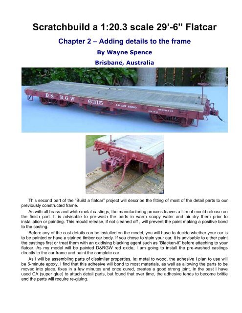
<strong>Scratchbuild</strong> a 1:<strong>20.3</strong> <strong>scale</strong> 29’-<strong>6”</strong> <strong>Flatcar</strong><br />
Chapter 2 – Adding details to the frame<br />
By Wayne Spence<br />
Brisbane, Australia<br />
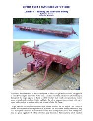
This second part of the “Build a flatcar” project will describe the fitting of most of the detail parts to our<br />
previously constructed frame.<br />
As with all brass and white metal castings, the manufacturing process leaves a film of mould release on<br />
the finish part. It is advisable to pre-wash the parts in warm soapy water and air dry them prior to<br />
installation or painting. This mould release, if not cleaned off , will prevent the paint making a positive bond<br />
to the casting.<br />
Before any of the cast details can be installed on the model, you will have to decide whether your car is<br />
to be painted or have a stained timber car body. If you chose to stain your car, it is advisable to either paint<br />
the castings first or treat them with an oxidising blacking agent such as “Blacken-it” before attaching to your<br />
flatcar. As my model will be painted D&RGW red oxide, I am going to install the pre-washed castings<br />
directly to the car frame and paint the <strong>com</strong>plete car.<br />
As I will be assembling parts of dissimilar properties, ie: metal to wood, the adhesive I plan to use will<br />
be 5-minute epoxy. I find that this adhesive will bond to most materials, as well as allowing the parts to be<br />
moved into place, fixes in a few minutes and once cured, creates a good strong joint. In the past I have<br />
used CA (super glue) to attach detail parts, but found that over time, the adhesive tends to be<strong>com</strong>e brittle<br />
and the parts will require re-gluing.
Please note that the details listed in the “parts list”, are only a guide to the parts required. Many of these<br />
details are available from other suppliers not listed and of course if you are skilled at casting your own<br />
parts, this would be an advantage.<br />
Now to continue constructing your flat...<br />
Here I have used Ozark Miniatures brake cylinder casting. The kit contains five pieces: the cylinder,<br />
piston rod, a tree of nut/bolt castings and two mounting plates. Orientate the mounting plates, as shown in<br />
the above photo and use 5-minute epoxy to mount the cylinder to the plates. Once the glue has cured,<br />
install the <strong>com</strong>pleted assemble to the frame with epoxy and drilling small holes, install the nut/bolt castings<br />
supplied in the kit. Using the underfloor drawing as a guide, install the eight 12” queen posts. The centres<br />
of the queen posts are to be positioned to the outer edges of the centre sill beams. I use 12” queen posts<br />
for that “lowslung” look, 9” posts would be more prototypical. Set aside to dry.
The installation of the truss rods is the most difficult part of building this flatcar. For this project I use<br />
relatively cheap 1.5mm welding rod, available from welding supply shops. Brass rod (0.0<strong>6”</strong>) can also be<br />
used. Two 2’-0” length’s or 1250mm will be required. Cut 4 rods 285mm (11.22”) to length. To bend the<br />
rods, measure 100mm (3.94”) in from each end and mark. Place the rod across 2 of the queen posts, the<br />
marks on the rod should be over the centres of the posts. Now remove the rod and using a pair of pliers,<br />
gently bend the rod down, using the marks as a guide to the bending point. Test fit the rod across the<br />
queen posts. The ends should just touch the underside of decking without lifting off the queen posts. Keep<br />
adjusting the rod till all 4 contact points are making contact with the car, as pictured. Bend the other 3<br />
remaining rods to shape. Note: the 2 inner truss rods may have to be trimmed to allow for the thickness of<br />
the lead weight, if installed. With all the rods bent to shape, place a small amount of 5 min. epoxy in the “u”<br />
shaped part of the queen post brackets and drop the newly formed truss rods into place. Make sure that<br />
the ends of the rods are hard up against the centre sill beams.
How do you attach the truss rod ends to the frame? On the prototype, the rods continue between the<br />
bolsters and deck, passing through the end beams where they are tensioned, using truss washers and<br />
nuts. I have used several methods of anchoring the ends of the rods, in modelling, taking them through to<br />
the beams is difficult and the results are somewhat disappointing. I have also bent the ends of the rods at<br />
right angles and inserted them into predrilled holes in the centre sills, but this requires very accurate<br />
measuring and bending to get it right. The easiest and most effective method is to simply just dribble some<br />
5-min. epoxy or hot glue directly onto the truss rod ends, which in turn bonds the rod to the frame. Once<br />
the underside of the car has been painted, these lumps of glue are hardly noticeable and will be totally<br />
invisible when the car is in operation on the track.<br />
While waiting for the truss rods to cure in place, now would be a good time to cut the mounting block for<br />
the Accucraft couplers from 10mm ply and glue in place (see drawing sheet 2). If you plan to use another<br />
type of coupler, leave out this step. Coupler installation will be covered in chapter 3.<br />
Using a drill press to keep the hole square, drill a 1/8” hole through the centre of one end of the end<br />
beam for the brake staff. This hole is measured in 30mm from the outer edge of the side sill beam. (see<br />
drawing on sheet 5). Temporally insert a short length of the welding rod into the hole to act as a guide to<br />
fixing the bottom bracket in place. Remove the rod once the bracket is secured to the frame.
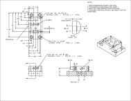
Referring to the end beam drawing on sheet 1, mark the position of the truss rod washers and nuts,<br />
drop grab irons and fix into place using 5-minuit epoxy. Drill a hole part way through end of the side sill and<br />
end beam and install nut-bolt-washer castings. On the prototype, the head of this bolt is hidden under the<br />
first deck plank. Repeat installing the end beam hardware to the other end of the car.<br />
Refer to sheets 3 and 4 for locations of the 6 per side cast stake pockets. While supporting your car on<br />
its side, epoxy the stake pockets in place, they should rest up against the decking planks. Continue<br />
installing the pockets on the other side of the car. Mark the position of the four side sill mounted steps, as<br />
shown in the above photo. Depending on the manufacture, the steps may have nuts and bolts cast on the<br />
mounting ends of these steps. These Ozark strap steps only have pre-drilled holes for nut/bolt/washer<br />
separate castings. As these steps are subject to unavoidable accidents, I have replaced two of the NBW<br />
castings on each bracket with brass bolts for extra strength. This is an option only.
Here are 3 examples of side mounted steps with cast on NBW detail.<br />
Time to add those great looking turnbuckles to the truss rods. These are very visible on a flatcar and I<br />
think they are worth installing, as they add that interesting “lowslung” detail, that I love on narrow gauge<br />
cars.<br />
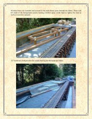
Take four of those left over deck planks and temporary clamp them across the truss rods as shown.<br />
These clamps will help keep the rods in place while they are being cut to allow for the installation of the<br />
tensioning turnbuckles.<br />
Using a felt tip marking pen, mark the centre of the truss rods, ie: centre point between the queen<br />
posts. Mark the section to be removed, 4.5mm out each side of the centre line mark for cutting. Using side<br />
cutting pliers or a cutting wheel in a Dremel tool, cut the outer rods only. Leave the centre rods straight<br />
through for now, this helps to keep the rods in alignment.
Next, apply 5-min. epoxy to both ends of the cut truss rod and slide the Ozark slotted turnbuckle into<br />
place. When you are satisfied with its location, squeeze the ends closed using thumb and forefinger<br />
pressure only. Cut the other outer rod and install the turnbuckle. Make sure that all the slots line up with<br />
each other. When the epoxy has set up, cut the inner rods and repeat the turnbuckle installation. The<br />
reason I only cut 2 rods at one time, is that the rods tend to flex out of alignment if all 4 rods were to be cut<br />
at once. The turnbuckles are very visible and must be installed as straight as possible. Latter on, we will<br />
slide a length of lumber through all of the turnbuckles, in real life, this practice prevents the turnbuckles<br />
from vibrating loose. The plank is usually wired in place.<br />
Note: Hartford Products, Trackside Details and others, also offer turnbuckles in varying styles.
All four turnbuckles installed, notice how the slots line up with each other!!<br />
Once the epoxy has cured, the truss rods will retain almost all of their original strength.
Top view of <strong>com</strong>pleted rods and queenposts<br />
Underview example of locking turnbuckle board. Note full brake detail on this car. (C&S cinder car)
Test fit trucks to check clearances from truss rods. Inner rods maybe bent slightly to increase<br />
clearance, if required.<br />
Turn your car over onto its test trucks and check clearances with the car mounted on a section of track.<br />
Using a small knife blade or file, cut a section of the decking away from the stake pockets, as shown in the<br />
photo above. This will allow stakes to be installed in the pockets, if required. Normal stakes are usually<br />
4”x4” posts, tapered at the base.
Referring to drawing sheets 3 and 4, drill holes for the bolster to side sill mounting bolts and glue in<br />
eight NBW castings, as shown.<br />
That's it for this chapter. The next chapter will include:<br />
Selecting and installing trucks.<br />
Selecting and installing couplers.<br />
Installing brakes and rigging.