
Create successful ePaper yourself
Turn your PDF publications into a flip-book with our unique Google optimized e-Paper software.
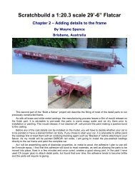
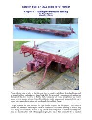
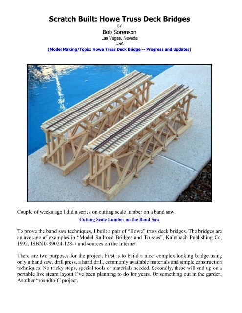
Scratch Built: Howe Truss Deck Bridges<br />
BY<br />
<strong>Bob</strong> <strong>Sorenson</strong><br />
Las Vegas, Nevada<br />
USA<br />
(Model Making/Topic: Howe Truss Deck Bridge -- Progress and Updates)<br />
Couple of weeks ago I did a series on cutting scale lumber on a band saw.<br />
Cutting Scale Lumber on the Band Saw<br />
To prove the band saw techniques, I built a pair of “Howe” truss deck bridges. The bridges are<br />
an average of examples in “Model Railroad Bridges and Trusses”, Kalmbach Publishing Co,<br />
1992, ISBN 0-89024-128-7 and sources on the Internet.<br />
There are two purposes for the project. First is to build a nice, <strong>com</strong>plex looking bridge using<br />
only a band saw, drill press, a hand drill, <strong>com</strong>monly available materials and simple construction<br />
techniques. No tricky steps, special tools or materials needed. Secondly, these will end up on a<br />
portable live steam layout I’ve been planning to do for years. Or something out in the garden.<br />
Another “roundtoit” project.
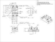
The bridges generally follow real practice. The truss rods are functional and under considerable<br />
tension. Very little glue is used. Lots if nails and #2-56 nut, bolt, washers. To start on the<br />
project, draw a full-scale truss panel section. Draw it out carefully so you can take<br />
measurements from it during construction.<br />
Truss Panel Plan<br />
The panel drawing is in 1:1 dimensions. This bridge project is<br />
scaled 1:20.3. That will make a very stout narrow gauge bridge 69<br />
feet in length. It will look just right for a light bridge in 1:13.7 scale,<br />
spanning 47 feet.<br />
It is helpful to have a table of standardized scale lumber dimensions.<br />
This table rounds dimensional lumber to 1:20.3 scale to the nearest<br />
1/32”. Well within the accuracy of the band saw.
The project proceeds in 4 phases:<br />
1. First is the deck section.<br />
2. Second the truss assemblies.<br />
3. Third the end bents.<br />
4. Lastly, final assembly.<br />
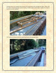
Start first with the deck stringers. The stringers<br />
are 2 sets of 3 timbers 8" x 18" ganged<br />
together. Between the stringer timbers, insert<br />
2” lengths of 1/16” thick plywood or leftover<br />
strip wood as spacers. Use 5 spacers over the<br />
stringer length.<br />
Add some detail to the stringer sets using 18<br />
gauge nails to simulate bolts for mending or<br />
splicing plates. Use a 2” length of angle as a<br />
template to drill pilot holes for the nails.<br />
Glue the stringers and spacers.
Hold the jig in place by hand and drill pilot<br />
holes for the nails. 18 gauge nails are 0.047”<br />
diameter, so use a #57 or #57 drill.<br />
Install the 12 x 18 floor beams to the bottom<br />
of the stringer sets. This is done using short<br />
lengths of 3/16” diameter wooden dowel pin<br />
and glue. The stringers and floor beams go<br />
together with a drop of glue, “tinker toy” style.<br />
Drive in the nails. Makes a nice looking detail.<br />
That’s it for today, next time we will finish the<br />
bridge deck.<br />
Drilling for the dowel pins requires a little<br />
precision. Mark out the hole locations on the<br />
stringers and floor beam. Clamp a length of<br />
straight edge on the drill press table so the drill<br />
center is on the center of the stringer. Align the<br />
drill by eye with your mark. Set the drill press<br />
stop for consistent depth.
Drill the holes along the length of the stringer. Flip it end for end to drill the other side of the<br />
stringer. Re-adjust the straight end to drill the center stringer member. This is a very quick and<br />
consistent method to drill holes along the edge of a board.<br />
Use the same technique to drill the floor<br />
beams. The floor beans need additional holes<br />
to receive the truss hanger rods during final<br />
assembly. Drill them now while the pieces are<br />
easy to handle.<br />
Now install the 8 x 8 ties using 18 gauge nails,<br />
1 inch long. Make an “L” shaped drilling jig<br />
from some scrap material.<br />
Cut lengths of the wooden dowel and slightly<br />
chamfer the ends. Glue them into the floor<br />
beams first. And then assemble with the<br />
stringers. A light tap with a soft mallet and<br />
they go right in.
Mark one tie with the hole locations, use it as a<br />
master to set the drilling jig. Clamp the jig to<br />
the drill press table aligned with the marking<br />
on the tie. Set a tie in the jig and drill.<br />
As before turn the ties end for end and drill.<br />
Since the ties are centered on the stringers, one<br />
jig setting will drill two holes. This is a very<br />
fast drill method. I drilled 6 holes in 100 ties in<br />
less then an hour.<br />
Nail down the ties starting from the center of<br />
the stringers and moving towards the ends.<br />
Apply a little glue to the tie. Center on the<br />
stringer with a ruler; square it with a square;<br />
space it with another tie. Holding by hand, use<br />
a hand drill to drill pilot holes into the<br />
stringers. Use a #57 or #58 drill so the nails go<br />
in just a bit tight. Drive in the nails. Repeat a<br />
bunch of times.<br />
The process of nailing ties looks tedious, but it’s not. After 2 or 3 you get the hang of it and it<br />
goes quickly.<br />
Next is the guardrail or guard cap. It is a 6 x 8<br />
cap nailed on the end of the ties. Drill #60<br />
pilot holes thru the guard cap using the straight<br />
edge fence on the drill press table. Use glue<br />
and tiny 20 gauge nails to spike it down. No<br />
pilot holes are need in the ties.
Go ahead and spike down some rail to the ties.<br />
It is easier to do it now rather after final<br />
assembly. This is code 250 aluminum rail, but<br />
use whatever you have.<br />
With that, the deck assembly phase is done.<br />
Next time we will work on the truss<br />
assemblies.<br />
The braces are assembled to the angle blocks<br />
by a 1/8” diameter wooden dowel pin. Here is<br />
how that works.<br />
To start on the trusses, here’s an assembled<br />
truss with some nomenclature for the parts.<br />
Now that we know the answer, let’s work thru<br />
the steps. First making the angle blocks. A<br />
strip of angle block material is cut from the<br />
edge of a 3/4" board. Tip the band saw table to<br />
45 degrees and clamp on a fence in the same<br />
manner as a regular rip cut.
Run the board thru the saw taking a diagonal<br />
cut. One cut is all. Use the sliding table and<br />
cross cut stop to cut off individual blank angle<br />
blocks.<br />
Next step is to drill the angle blocks for the<br />
1/8” pins in the braces. Tip the drill press table<br />
to 45 degrees and clamp on the drilling jig you<br />
used to drill the ties.<br />
The angle blocks have different hole arrangements. Some have three holes on one side and one<br />
on the other. Some are two and two; some are two and one. Carefully inventory the plan so you<br />
drill them correctly. You don’t want an unused hole or <strong>com</strong>e up short.<br />
Next glue the angle block to the chords.
Now it’s time to drill the braces. Turn the drill<br />
press table to 90 degrees. Clamp on some<br />
straight edges for guides and stops. Drill both<br />
ends of the brace.<br />
Add some cleats on the top side of the bottom<br />
chord and shoes to the bottom.<br />
Get ready to assemble the trusses. Cut short<br />
lengths of 1/8” dowel and glue them in the<br />
braces. The brace ends that go in the angle<br />
blocks are dry. DO NOT try to glue the braces<br />
into the angle blocks. Insert braces into the<br />
angle block on the bottom chord. Insert braces<br />
into the top chord starting at one end and<br />
working to the other. This is real fiddle work,<br />
need about 59 hands for this. Eventually they<br />
go together. Tap down with your hand to seat<br />
all the braces.
Let’s have a look at the progress. Looking<br />
nice. Next time we’ll work on the end bents.<br />
Next get the bent posts and bottom beam cut<br />
and drilled for 3/16” dowels. Measure the<br />
lengths of the bents from the actual project,<br />
not the plan. By now errors have crept in and<br />
the plan is only guidance. That’s about it for<br />
fabrication of the bents. The rest of the bents<br />
go together during final assembly.<br />
Cleats and shoes go on with nails and glue.<br />
The cleats are very important. The outboard<br />
angle block on the bottom chord has no<br />
support other then some glue. It will snap off<br />
when the truss rods are tightened. Makes sure<br />
the cleats are tight against the angle block,<br />
well glued and nailed.<br />
Let’s get on the end bents, final assembly and<br />
wrap this project up. The end bent assemblies<br />
are straightforward. They are made up using<br />
the glue and dowel pin technique as on the<br />
deck assembly. The first thing to do is attach<br />
the top beam to the stringers.
Now it’s time to start final assembly. First cut<br />
the 12 x 12 bottom stunts that go under the<br />
trusses. Drill them for truss rods to match the<br />
floor beams above. The bottom struts need a<br />
short length of 1/8” dowel to secure them to<br />
the trusses.<br />
Those 1/8” dowels holding the bottom struts in place are important. They assist in getting the<br />
bridge together. They also prevent the bottom struts from getting knocked out of place if the<br />
bridge gets bumped by accident.<br />
Now for the truss rods. There are 3 options. First is to use solid rod and run a threading die over<br />
the end. The second is to use “all thread” rod. The third is to use bicycle spokes.<br />
The most realistic option is solid rod. However it requires a die to cut the threads, which is a<br />
specialized tool. Solid rod is somewhat difficult to die unless you have a way to align the die to<br />
the rod. Eye balling it is kind of difficult. For this project I wanted to avoid special tools and<br />
methods.<br />
Bicycle spokes <strong>com</strong>e in various lengths and are threaded on one end. I have not tried them, but<br />
I am sure they work fine.<br />
I went with #2 x 56 “all thread” rod for this project. All thread in this size is available in 6-foot<br />
lengths from McMaster Carr. #2 x 56 is a bit larger then M2. Use M2 or M2.5 if that’s<br />
available.<br />
To assemble, set the trusses on the bottom<br />
struts and place the deck on top. Have an extra<br />
set of hands available. Cut lengths of all<br />
thread. Put a nut and washer on one end. Drop<br />
it down thru the holes and put another nut and<br />
washer at the bottom. Tighten each rod a little<br />
at the time until all the braces pull down tight<br />
on the angle blocks.
Use two washers against each nut. One washer is a regular, the other an extra wide fender<br />
washer. Fender washers distribute pressure better and won’t dent the wood. Regular sized #2 x<br />
56 nuts will work fine, but don’t look right. Use “small pattern” nuts or model hex nuts.<br />
McMaster Carr has small pattern nuts.<br />
Position the bents plumb and square. Place a<br />
clamp across the truss to hold the bents in<br />
place.<br />
Next, install the end bents. Turn the bridge up<br />
side down and drop in the bents.<br />
Drill a 3/16” whole thru the truss shoes into<br />
the bottom bent beam. Glue in a length of<br />
3/16” dowel.
Install 6 x 12 cross bracing on the truss ends.<br />
And finally, install 6 x 12 cross bracing on the<br />
end bents. I forgot to mention drilling all the<br />
holes for cross bracing and stretcher rods<br />
ahead of time. Carefully <strong>com</strong>e up with a<br />
drilling plan so you all that before everything<br />
is assembled.<br />
Install #2 x 56 stretcher rods between the<br />
bottom chords. Use nuts and washers on both<br />
sides of the bottom chords.<br />
Well, that’s it. Ready to install on the pike.<br />
While they look <strong>com</strong>plicated, they are not<br />
difficult to do. Every dimension cut was taken<br />
on the band saw. A drill press and a hand drill<br />
were the only other power tools. There were<br />
no tricky or hidden steps. All hardware and<br />
materials easily available.<br />
Thanks to everyone for their kind word and stopping by for a look.