
Create successful ePaper yourself
Turn your PDF publications into a flip-book with our unique Google optimized e-Paper software.
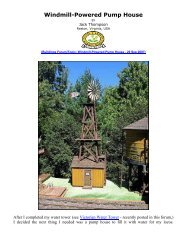
Scratch-build a 1:20.3 scale 29’-6” Flatcar<br />
Chapter 1 – Building the frame and decking<br />
By <strong>Wayne</strong> <strong>Spence</strong><br />
Brisbane, Australia<br />
Please take the time to refer to the following link, in which Dwight Ennis describes his approach<br />
to scratch building his Backwater Water Tank. This fine water tank construction article takes you<br />
through all the steps required to build a 1:20.3 structure that would <strong>com</strong>plement any narrow<br />
gauge inspired garden railroad. It also highlights the safety requirements associated with use of<br />
power tools required to produce strip wood needed to build this flatcar.<br />
Dwight explains the need to select the right lumber required for this project. The choice of<br />
lumber will determine whether your flatcar is suitable for 'all weather' running or must be only<br />
used during fine conditions. As most of my scratch-built rolling stock is made from white (clear)<br />
pine and glued together with white carpenters glue, this makes them unsuitable for all weather,
all year round exposure. If your flatcar were to be exposed to the weather, your choice of<br />
construction materials would have to take this into consideration.<br />
Large-scale lumber will have to be resistant to the weather by either using proven timber such as<br />
redwood or cedar and applying a preservative or painting the model. Here in Australia we have<br />
several species of timber suitable for model making, including hardwoods, but I prefer to use<br />
white pine, the reason being that in my case, its free. This pine is leftover off cuts from a<br />
furniture manufacture. It is similar to basswood, same color and easy to work, but doesn't seem<br />
to have that "fuzz" that basswood produces. Don't forget to use a waterproof glue to assemble<br />
your rolling stock.<br />
http://www.mylargescale.<strong>com</strong>/articles/articles/WaterTank/Watertank02.asp<br />
This flatcar project will be constructed in four parts.<br />
Chapter 1 - Building the frame and decking.<br />
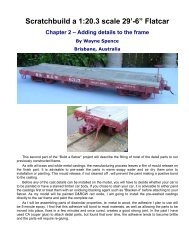
Chapter 2 - Adding the details to the frame.<br />
Chapter 3 - Trucks, couplers and brakes.<br />
Chapter 4 - Painting and decals.<br />
The Model<br />
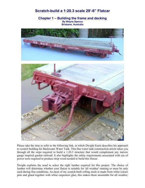
It is proposed to build a 29'-6" 3' narrow gauge flatcar, primarily from lumber, as used by the<br />
prototype. The car's construction loosely follows the designs used by the D&RGW, RGS, C&S,<br />
and several other NG roads, but is not of any particular prototype, rather a design suitable for<br />
'first time' modellers.<br />
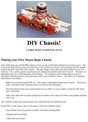
This car can be built from any suitably available lumber - you chose the type of trucks and<br />
couplers. The photo at the head of this chapter has had three additional longitudinal planks added<br />
to both sides of the deck. This flatcar was built, as a heavy-duty flat, suitable for transporting<br />
large pieces of machinery, like tracked logging dozers. This additional decking will be optional<br />
in this project. Note the rusty chain tie down eyes mounted on the deck.<br />
Downloading the Drawings<br />
Each chapter in this series will have links to 1:20 scale full sized drawings listed below. I made<br />
sure these would fit on a standard 8-1/2 x 11 piece of paper, and I've converted each to an Adobe<br />
Acrobat PDF file. To open/view these files will require that you have Adobe Acrobat Reader<br />
installed on your system, a free program used to share documents and drawings. If you don't<br />
have the Acrobat Reader, you can download it here. Once you have the Acrobat Reader<br />
installed, download the drawings and print one or more copies of them. The PDF files are<br />
designed to print 1:1, to make sure the Shrink to Fit box is unchecked!! The following drawings<br />
are for all 3 chapters:<br />
Detailed Materials List<br />
Sheet one - 1:1 scale template drawings.<br />
Sheet two - 1:1 scale template drawings.<br />
Sheet three - 1:1 scale construction plan, left-side view.<br />
Sheet four - 1:1 scale construction plan, right-side view.<br />
Sheet five - 1:1 scale construction plan, decking.<br />
Sheet six - ½ scale flatcar plan.<br />
Download All Drawings - 411K
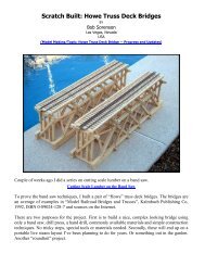
Let's Get Started!<br />
The above is the 10” bench type table saw that I used to rip the side sill beams, centre beam sills<br />
and end beams. Use feather sticks to guide the stock through to cutting blade.<br />
The above is the small bench band saw I use to rip the smaller sized lumber lengths.
The digital calipers are one of the best<br />
modelling tool investments that I have<br />
made over the years. They're great for<br />
marking out repetitive measurements and<br />
checking lumber sizes.<br />
Gentlemen Start Your Saws!<br />
Once side sills have been cut to length,<br />
mark out area to be checked out and using<br />
the band saw, make a parallel cut to the<br />
line, 7mm from the end - as shown, using<br />
the preset guide fence to cut both ends of<br />
both left and right side sills.<br />
Remove saw fence and crosscut saw<br />
remaining cuts to remove cheek, using the<br />
saws mitre 'T' guide for accurate square<br />
cuts. If not using a band saw, these two<br />
cuts can be made with a fine tooth<br />
handsaw or razor saw, making sure that<br />
the cuts are square. The flatcar end beams<br />
will be located in these side sill checks.<br />
Cut the 115.5x10x7 end beams from your<br />
stock timber.
Use a razor saw or hacksaw blade to add<br />
some 'grain texture' to the outer side edges<br />
of the side sills and to the exposed sides of<br />
the end beams.<br />
Side sills and end beams have had 'grain<br />
texture' added, usually only one pass of<br />
the saw blade is sufficient.<br />
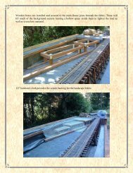
Lay side sills (check up) on a flat surface<br />
and wood glue beams in place. Beams<br />
should 'overhang' sills by 1.5mm at each<br />
side. Use scrap wood lengths cut 96.5mm<br />
long to use as spacers to maintain sill<br />
spacing until glue dries. Check with<br />
square to make sure sills and beams are at<br />
right angles.
Notice that the End Beam overhangs the<br />
side sill by 1.5mm. Set aside to dry,<br />
approximately 1 hour, if using white glue.<br />
Set guide fence on your table saw or band<br />
saw to cut decking from stock wood. I use<br />
stock about 1200mm long to cut my<br />
decking planks from. Cut strip wood to<br />
2.3mm widths first, then cut these 2.3mm<br />
lengths to 9.5mm stock (2.3mm x<br />
9.5mm). The decking really has to be cut<br />
with a power saw or purchased precut<br />
timber decking. As always, use caution<br />
when cutting small size lengths like this.<br />
Use 'push sticks' to guide wood though<br />
saw blade.
I pack the 9.5mm x 2.3mm lengths of<br />
decking stock that have just been cut, into<br />
2 rows of 10 (20 pieces) and using plastic<br />
tape, wrap tape around pack at about every<br />
100mm. Mark decking for 112mm lengths<br />
and cut into bundles, as shown in the<br />
foreground of the above photo.<br />
Note the stop block fixed to the right-hand<br />
side of the saw deck. A table saw or band<br />
saw could also be used to cut the decking<br />
bundles to length. This multi pack cutting<br />
saves a lot of time measuring and cutting<br />
individual deck planks.<br />
Add the decking..<br />
OK, time to fix the decking to the frame.<br />
Turn the car frame over (side sill and end<br />
beam flush at the ends). Apply wood glue<br />
to about the first 100mm of both sides of<br />
the frame and the top of the end beam.<br />
Start laying down the deck planking,<br />
check for square every eight or so planks.<br />
Don't try and push the planks too tightly<br />
together. You want the boards to appear<br />
as individual planking after the deck is<br />
sanded. Install remaining decking.<br />
Use scrap spacers to maintain frame width<br />
as the deck boards are glued into place.
At the other end, glue a full width plank to<br />
the end beam, if required, cut down a<br />
plank to <strong>com</strong>plete the deck. Note the<br />
1.5mm overhang, over the side sills.<br />
You’ve <strong>com</strong>pleted the decking..<br />
After the glue on the decking planks have<br />
dried, turn car deck over and mark<br />
positions on the bottoms of the end beams<br />
for the installation of the centre sill beams.<br />
Spread glue on to one edge of the centre<br />
sill and clamp in place. Repeat with the<br />
other centre sill beams.
Beams fixed in place, note spacing pencil<br />
marks on the underside of the end beam.<br />
Set aside to dry.<br />
Once frame and decking timbers are<br />
<strong>com</strong>pletely dry, sand back any high planks<br />
on the deck.<br />
To speed up the sanding process, I use<br />
several passes of the frame over a bench<br />
sander..
After sanding, highlight the individual<br />
planks by scribing along each joint. My<br />
scribe is an old sharpened screwdriver.<br />
(Not my hands, but my wife, Carol,<br />
helping with the photos)<br />
Lightly draw a pencil line along the full<br />
length of the both sides of the deck. Dead<br />
centre over the side sills. Notice the<br />
highlighted planks on the left-hand side.<br />
Using your scribe punch two 'nail holes' at<br />
each end of every plank. Sand off pencil<br />
line after all the embossed 'nail heads'<br />
have been punched.
As I run some of my flatcars empty, I like<br />
to add some extra weight to help the car<br />
track better. If you also wish to weight<br />
your car, cut two 400mm lengths of sheet<br />
lead to fit between outer and inner centre<br />
sills. Lead can be cut with a sharp knife,<br />
similar to cutting styrene. Lead is approx.<br />
1.5mm thick.<br />
Using a glue gun is a quick way to fix<br />
down the lead to the underside of the<br />
deck.<br />
Cutout the needle beams from the<br />
template on sheet 2. If full brake rigging<br />
is to be modelled, it is advisable to locate<br />
and drill brake rod clearance holes, prior<br />
to installing the needle beams to the<br />
frame. Glue beams to frame and clamp.
Install end sill to end beam at both ends of<br />
car frame (32x10x7), making sure that<br />
they are centred on the end beam. Clamp<br />
with rubber band till glue bonds.<br />
Now we are ready to cut and install the<br />
bolster, to which the trucks are mounted.<br />
A bolster white metal or brass casting<br />
could be used to be more prototypes in<br />
construction, but for simplicity, I will use<br />
a 96.5mmx15mmx4.5mm wood bolster.<br />
Mark the centre hole position and drill a<br />
1/8" hole in each bolster. Insert a 4-40<br />
blind 'T' nut in each hole and tap home<br />
with a small hammer or squeeze together<br />
in bench vice.<br />
Glue bolster into position., make sure that<br />
the 'T' is on the bottom, i.e.: facing the<br />
decking.
For added strength, I drill through the<br />
bolster and insert two wood screws into<br />
two of the centre sills. Check to see that<br />
the screws are flush with the top of the<br />
bolster. If they are protruding, they may<br />
interfere with truck swing, once the trucks<br />
are installed.<br />
Test fit trucks, if using Hartford Products<br />
trucks, place two small washers between<br />
the bolsters and truck frames. I find that<br />
small 'fender' washers work best - 2x<br />
12mm washer with a 1/8 hole. Use a 4-40<br />
x ¾ socket head screw to mount the<br />
trucks.<br />
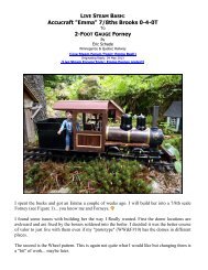
Well folks, that concludes Chapter 1.
On <strong>com</strong>pletion of chapter 2 your flat will look similar to this.<br />
Happy modelling,<br />
<strong>Wayne</strong>
Scratch-build a 1:20.3 scale 29’-6” Flatcar<br />
Chapter 2 – Adding details to the frame<br />
By <strong>Wayne</strong> <strong>Spence</strong><br />
Brisbane, Australia<br />
This second part of the “Build a flatcar” project will describe the fitting of most of the detail<br />
parts to our previously constructed frame.<br />
As with all brass and white metal castings, the manufacturing process leaves a film of mould<br />
release on the finish part. It is advisable to pre-wash the parts in warm soapy water and air dry<br />
them prior to installation or painting. This mould release, if not cleaned off, will prevent the<br />
paint making a positive bond to the casting.<br />
Before any of the cast details can be installed on the model, you will have to decide whether your<br />
car is to be painted or have a stained timber car body. If you chose to stain your car, it is<br />
advisable to either paint the castings first or treat them with an oxidising blacking agent such as<br />
“Blacken-it” before attaching to your flatcar. As my model will be painted D&RGW red oxide, I<br />
am going to install the pre-washed castings directly to the car frame and paint the <strong>com</strong>plete car.<br />
As I will be assembling parts of dissimilar properties, ie: metal to wood, the adhesive I plan to<br />
use will be 5-minute epoxy. I find that this adhesive will bond to most materials, as well as<br />
allowing the parts to be moved into place, fixes in a few minutes and once cured, creates a good<br />
strong joint. In the past I have used CA (super glue) to attach detail parts, but found that over<br />
time, the adhesive tends to be<strong>com</strong>e brittle and the parts will require re-gluing.
Please note that the details listed in the “parts list”, are only a guide to the parts required. Many<br />
of these details are available from other suppliers not listed and of course if you are skilled at<br />
casting your own parts, this would be an advantage.<br />
Now to continue constructing your flat...<br />
Here I have used Ozark Miniatures brake<br />
cylinder casting. The kit contains five<br />
pieces: the cylinder, piston rod, a tree of<br />
nut/bolt castings and two mounting plates.<br />
Orientate the mounting plates, as shown in<br />
the above photo and use 5-minute epoxy<br />
to mount the cylinder to the plates. Once<br />
the glue has cured, install the <strong>com</strong>pleted<br />
assemble to the frame with epoxy and<br />
drilling small holes, install the nut/bolt<br />
castings supplied in the kit. Using the<br />
under floor drawing as a guide, install the<br />
eight 12” queen posts. The centres of the<br />
queen posts are to be positioned to the<br />
outer edges of the centre sill beams. I use 12” queen posts for that “lows-lung” look, 9” posts<br />
would be more prototypical. Set aside to dry.<br />
The installation of the truss rods is the<br />
most difficult part of building this flatcar.<br />
For this project I use relatively cheap<br />
1.5mm welding rod, available from<br />
welding supply shops. Brass rod (0.06”)<br />
can also be used. Two 2’-0” length’s or<br />
1250mm will be required. Cut 4 rods<br />
285mm (11.22”) to length. To bend the<br />
rods, measure 100mm (3.94”) in from<br />
each end and mark. Place the rod across 2<br />
of the queen posts, the marks on the rod<br />
should be over the centres of the posts.<br />
Now remove the rod and using a pair of<br />
pliers, gently bend the rod down, using<br />
the marks as a guide to the bending point. Test fit the rod across the queen posts. The ends<br />
should just touch the underside of decking without lifting off the queen posts. Keep adjusting the<br />
rod till all 4 contact points are making contact with the car, as pictured. Bend the other 3<br />
remaining rods to shape. Note: the 2 inner truss rods may have to be trimmed to allow for the<br />
thickness of the lead weight, if installed. With all the rods bent to shape, place a small amount of<br />
5 min. epoxy in the “u” shaped part of the queen post brackets and drop the newly formed truss<br />
rods into place. Make sure that the ends of the rods are hard up against the centre sill beams.
How do you attach the truss rod ends to<br />
the frame? On the prototype, the rods<br />
continue between the bolsters and deck,<br />
passing through the end beams where they<br />
are tensioned, using truss washers and<br />
nuts. I have used several methods of<br />
anchoring the ends of the rods, in<br />
modelling, taking them through to the<br />
beams is difficult and the results are<br />
somewhat disappointing. I have also bent<br />
the ends of the rods at right angles and<br />
inserted them into predrilled holes in the<br />
centre sills, but this requires very accurate<br />
measuring and bending to get it right. The<br />
easiest and most effective method is to<br />
simply just dribble some 5-min. epoxy or<br />
hot glue directly onto the truss rod ends,<br />
which in turn bonds the rod to the frame.<br />
Once the underside of the car has been<br />
painted, these lumps of glue are hardly<br />
noticeable and will be totally invisible<br />
when the car is in operation on the track.<br />
While waiting for the truss rods to cure in<br />
place, now would be a good time to cut<br />
the mounting block for the Accucraft<br />
couplers from 10mm ply and glue in place<br />
(see drawing sheet 2). If you plan to use<br />
another type of coupler, leave out this<br />
step. Coupler installation will be covered<br />
in chapter 3.
Using a drill press to keep the hole square,<br />
drill a 1/8” hole through the centre of one<br />
end of the end beam for the brake staff.<br />
This hole is measured in 30mm from the<br />
outer edge of the side sill beam. (See<br />
drawing on sheet 5). Temporally insert a<br />
short length of the welding rod into the<br />
hole to act as a guide to fixing the bottom<br />
bracket in place. Remove the rod once the<br />
bracket is secured to the frame.<br />
Referring to the end beam drawing on<br />
sheet 1, mark the position of the truss rod<br />
washers and nuts, drop grab irons and fix<br />
into place using 5-minuit epoxy. Drill a<br />
hole part way through end of the side sill<br />
and end beam and install nut-bolt-washer<br />
castings. On the prototype, the head of<br />
this bolt is hidden under the first deck<br />
plank. Repeat installing the end beam<br />
hardware to the other end of the car.<br />
Refer to sheets 3 and 4 for locations of the<br />
6 per side cast stake pockets. While<br />
supporting your car on its side, epoxy the<br />
stake pockets in place, they should rest up<br />
against the decking planks. Continue<br />
installing the pockets on the other side of<br />
the car. Mark the position of the four-side<br />
sill mounted steps, as shown in the above<br />
photo. Depending on the manufacture, the<br />
steps may have nuts and bolts cast on the<br />
mounting ends of these steps. These<br />
Ozark strap steps only have pre-drilled<br />
holes for nut/bolt/washer separate<br />
castings. As these steps are subject to<br />
unavoidable accidents, I have replaced<br />
two of the NBW castings on each bracket with brass bolts for extra strength. This is an option<br />
only.
Here are 3 examples of side-mounted steps with cast on NBW detail.<br />
Time to add those great looking<br />
turnbuckles to the truss rods. These are<br />
very visible on a flatcar and I think they<br />
are worth installing, as they add that<br />
interesting “lows-lung” detail that I love<br />
on narrow gauge cars. Take four of those<br />
left over deck planks and temporary<br />
clamp them across the truss rods as<br />
shown. These clamps will help keep the<br />
rods in place while they are being cut to<br />
allow for the installation of the tensioning<br />
turnbuckles. Using a felt-tipped marking<br />
pen, mark the centre of the truss rods, i.e.:<br />
centre point between the queen posts.<br />
Mark the section to be removed, 4.5mm out each side of the centre line mark for cutting. Using<br />
side cutting pliers or a cutting wheel in a Dremel tool, cut the outer rods only. Leave the centre<br />
rods straight through for now, this helps to keep the rods in alignment.<br />
Next, apply 5-min. epoxy to both ends of<br />
the cut truss rod and slide the Ozark<br />
slotted turnbuckle into place. When you<br />
are satisfied with its location, squeeze the<br />
ends closed using thumb and forefinger<br />
pressure only. Cut the other outer rod and<br />
install the turnbuckle. Make sure that all<br />
the slots line up with each other. When the<br />
epoxy has set up, cut the inner rods and<br />
repeat the turnbuckle installation. The<br />
reason I only cut 2 rods at one time, is that<br />
the rods tend to flex out of alignment if all<br />
4 rods were to be cut at once. The<br />
turnbuckles are very visible and must be<br />
installed as straight as possible. Latter on, we will slide a length of lumber through all of the<br />
turnbuckles, in real life, this practice prevents the turnbuckles from vibrating loose. The plank is<br />
usually wired in place.<br />
Note: Hartford Products, Trackside Details and others, also offer turnbuckles in varying styles.
All four turnbuckles installed, notice how<br />
the slots line up with each other!!<br />
Once the epoxy has cured, the truss rods<br />
will retain almost all of their original<br />
strength.<br />
Top view of <strong>com</strong>pleted rods and queen<br />
posts.
Underview example of locking turnbuckle<br />
board. Note full brake detail on this car.<br />
(C&S cinder car)<br />
Test fit trucks to check clearances from<br />
truss rods.<br />
Inner rods may need to be bent slightly to<br />
increase clearance, if required.<br />
Turn your car over onto its test trucks and<br />
check clearances with the car mounted on<br />
a section of track. Using a small knife<br />
blade or file, cut a section of the decking<br />
away from the stake pockets, as shown in<br />
the photo above. This will allow stakes to<br />
be installed in the pockets, if required.<br />
Normal stakes are usually 4”x4” posts,<br />
tapered at the base.
Referring to drawing sheets 3 and 4, drill holes for the bolster to side sill mounting bolts and glue<br />
in eight NBW castings, as shown.<br />
That's it for this chapter. The next chapter will include:<br />
Selecting and installing trucks.<br />
Selecting and installing couplers.<br />
Installing brakes and rigging.
Scratch-build a 1:20.3 scale 29’-6” Flatcar<br />
Chapter 3 – Installing Trucks, Couplers & Brakes<br />
By <strong>Wayne</strong> <strong>Spence</strong><br />
Brisbane, Australia<br />
The Trucks<br />
For this flatcar project, I will be using as my preference, Hartford Products cast white metal truck<br />
kits. I find that these trucks have excellent detail and because of their weight, track very well<br />
over less than perfect track. There are many other manufactures building prototypical cast trucks,<br />
which can purchased as detail parts, so I will leave the type of truck you wish to use as your<br />
personal choice. I will also show how the “standard” Bachmann truck can be used with body<br />
mounted couplers and be fitted with brake beams.<br />
HP-T001-26<br />
Archbar trucks with 26”<br />
diameter trucks<br />
HP-T003<br />
D&RGW 3’-7” trucks<br />
HP-T004<br />
Carter Brothers swing motion 4’<br />
The Couplers<br />
Most narrow gauge Colorado roads use a ¾ size knuckle coupler, with the exception of the<br />
D&RGW who choose to fitted all their rolling stock with standard gauge size knuckle couplers.<br />
This chapter will describe how I fit body-mounted couplers to the flatcar. Body mounting<br />
couplers will require a minimum track curve radius of four feet. The couplers I will be using for<br />
this car will be Accucrafts 1:20.3 knuckle type. An option for installing Kadees #1 gauge 820<br />
series or “G” gauge 830 series can also be installed on this car.<br />
Bachmann’s truck mounted couplers will be able to be used if consideration is given to the<br />
clearances required from the body-mounted details, such as the brake valve and air hose.
The Brakes<br />
Adding brake beam detail to Hartford Products and Bachmann trucks<br />
If you choose to use Hartford’s Carter Brothers swing motion trucks, the end beams are included<br />
in the kit. Car brake details will include, brake wheel & pawl, hoses, pipes, air cylinder castings<br />
and limited under car rigging.<br />
Make 4 cut-lever mounting eyelets by<br />
cutting approximately 10mm of fish<br />
hooks or bend 1.2mm brass wire into<br />
eyelets. We will be using large paper clips<br />
or 1.2 brass wire for the cut levers, so test<br />
the fish hook eye size by inserting the<br />
wire though the eye for a snug fit. Select<br />
suitable sized hooks.<br />
Drill suitable eyelet mounting holes in<br />
the end beam as shown and epoxy into<br />
place, making sure that the eyes are<br />
parallel to each other. Insert a scrap<br />
length of wire through the eyes to<br />
maintain the right position until the<br />
epoxy sets up.<br />
Note: the centre eyelet hole is drilled at<br />
an angle of approx. 45 degree’s into the<br />
end beam, rather than into the deck<br />
plank.<br />
Epoxy brake pawl into position, using the<br />
brake staff to line up the pawl with the hole through the beam and the lower brake bracket. Refer<br />
to sheet 1 for position of cut lever eyes.<br />
I like to use large straighten out paper<br />
clips for the cut levers. These clips seem to<br />
be softer to bend to shape than brass rod<br />
and are a cheap alterative, just keep<br />
bending clips till you have the right shape.<br />
Bend up the “handle” (outer) end first,<br />
insert the lever through the eyes, and then<br />
bend the other end at right angles. Don’t<br />
trim the lever excess till the couplers have<br />
been installed. The end of the lever should<br />
be directly over the top of the coupler trip<br />
pin. Repeat the cut lever installation to the<br />
other end of the car.
If you are using the Hartford or Ozark<br />
brake wheel casting, you will need to<br />
make a brake staff. Cut a 65mm length of<br />
the same welding rod that was used to<br />
make the truss rods. Clean out the<br />
mounting hole cast into the under side of<br />
the brake wheel and epoxy into place. Cut<br />
a small collar of brass or styrene tubing<br />
and glue into place about 38mm down<br />
from the brake wheel.<br />
This collar will prevent the brake staff<br />
from falling <strong>com</strong>pletely through end beam<br />
and make it easy to remove the staff for<br />
painting or for transporting the <strong>com</strong>pleted car, without damaging the brake wheel.<br />
Test fit the <strong>com</strong>pleted brake staff into the<br />
pawl and lower bracket.<br />
The brake staff should protrude about<br />
3mm below the bottom of the lower brake<br />
bracket. The staff can be secured in place<br />
by slipping a small slice in PVC cable<br />
insulation over the bottom of the brake<br />
rod.
Installing body mounted couplers<br />
Instructions on installing Accucraft couplers to our flatcar.<br />
Remove the four nuts and bolts from the<br />
coupler faceplate, only the bolts will be<br />
required latter. Remove the vertical bolt<br />
behind the faceplate; this bolt and nut<br />
won’t be required. Using the coupler<br />
pocket as a drilling template, position the<br />
coupler on the end beam and mark the four<br />
mounting hole positions. Drill four 1.5mm<br />
holes in the end beam.<br />
Using a suitable socket driver, screw the<br />
supplied bolts though the faceplate<br />
directly into the wooden end beam.<br />
Now turn the car <strong>com</strong>pletely over and drill<br />
a 1.3mm hole through the bottom<br />
mounting plate into the end beam, taking<br />
care not to drill into or through the deck.<br />
Install a suitable length screw through the<br />
coupler body into the end beam. Check<br />
the knuckle for maximum horizontal<br />
swing.<br />
Note: I install a small washer between the<br />
knuckle shaft and coupler body to<br />
minimise “knuckle droop”.<br />
On <strong>com</strong>pletion of the next step (installing<br />
truck spacer blocks). Check coupler-mounting height – centre of knuckle to railhead. 1:20.3 =<br />
32.5mm.
Make two small coupler lift rings by<br />
winding a length of brass wire around a<br />
drill bit. Cut the wire to form to rings.<br />
Open up the ring slightly and slide on<br />
about six links of light chain. Loop ring<br />
through top of coupler lift pin, close ring<br />
with pliers and add a drop of solder to<br />
secure the joint in the ring. Next trim the<br />
chain to length, and then slip the last link<br />
of the chain onto the lift bar. The link can<br />
be soldered to the bar or bend the bar over<br />
the chain link to form a loop.<br />
The Accucraft coupler installation is<br />
<strong>com</strong>pleted.<br />
Instructions on installing Kadee couplers to our flatcar.<br />
#830 or #820 type.<br />
Assemble the Kadee coupler box as per the<br />
instructions. As I don’t use under track<br />
magnetic coupler operations, I cut off the<br />
couplers “air hose” and file the pin<br />
smooth. Mount the coupler box directly to<br />
the end beam with two 15mm round head<br />
wood screws. Use wood or styrene shims<br />
to maintain correct coupler height.<br />
Check coupler-mounting height – centre of<br />
knuckle to railhead. 1:20.3 = 32.5mm.<br />
Two wood screws secure the coupler box<br />
to the end beam. The third centre screw is<br />
not accentual, but can be inserted into a<br />
short piece of timber glued in between the<br />
two inner sills.
Brake Details<br />
Attach the brake valve to the bracket<br />
(these are part of the Ozark brake hose<br />
set) with epoxy. Mount the bracket to the<br />
underside of the end beam. This fitting is<br />
normally located on the opposite side to<br />
the brake wheel. The bracket can also be<br />
alternatively attached to the vertical side<br />
of the coupler block, but if this location<br />
is used, make sure that the valve is<br />
rotated 45 degrees on the bracket. Epoxy<br />
the bracket to the beam and insert two<br />
NBW castings. The plastic hose and<br />
glad, hand supplied in the kit, can be<br />
installed last before painting, to reduce<br />
accidental damage to the valve assembly.<br />
If you are installing Hartford Products<br />
trucks or similar, styrene spacer blocks<br />
will be required to be mounted to the<br />
wood bolsters. From 2mm styrene, cut a<br />
centre spacer 16mm x 12mm and weld a<br />
1mm layer on top to form a 3mm thick<br />
block. Note that 3mm styrene can be<br />
used, but this sized styrene maybe hard<br />
to find.<br />
Fit<br />
the 4.5mm mounting blocks to only one bolster, in positions 2 and 3, as shown above. The<br />
other bolster will only require the centre truck-mounting block fixed in position 1. I have found<br />
that using this three-way set-up reduces the amount of car “wobble” on uneven track and<br />
maintains a level car ride through the curves. The truck at position 1 allows the truck to follow<br />
any undulating track and the truck at the other end (position 2/3), supports and holds the car in a<br />
level position.
Test fit the trucks. Tighten the mounting screws to just firm, then back off the screws by about<br />
half a turn. Check that the trucks are free to rotate on a short length of test track. There should<br />
only be a very slight side-to-side movement when the car is rocked. Later when the trucks and<br />
the car deck have been painted, the truck mounting screws will be fixed in place with Loctite<br />
222.<br />
Next we will add brake beams and cast brake shoes to our trucks.<br />
Using Hartford Products HP-T001-26 archbar trucks<br />
If you want to add brake beam details to<br />
the Hartford Products trucks, I have<br />
successfully modified the trucks to<br />
incorporate this detail. Cut out the four<br />
brake beams from wood, using the<br />
template found on sheet 1. Or use<br />
Hartford Products kit HP-P079 (includes<br />
4 sets of wood beams & brake shoes).<br />
Using a wheel set as a spacing guide,<br />
epoxy the eight brake shoes to the four<br />
brake beams.<br />
Use Ozark or Hartford Products HP-P040<br />
brake shoe castings. Cut four lengths of<br />
K&S 1.13mm (.039”) music wire @ 120mm each. Drill wooden brake beams for music wire<br />
support rods. (32mm centres). Insert wires into one of the end beams, epoxy into place and allow<br />
enough hole length at the outer beam for a small NBW casting. Epoxy two small lengths of brass<br />
or styrene tubing to the under side of the truck centres (32mm spacing). Slide steel wire though<br />
tubes, slide on other brake beam, trim wires to length and secure with epoxy. The wire rods are<br />
not epoxied into the tubes, rather left free to automatically adjust to axle spacing.<br />
Detail brake beams with appropriate NBW castings. Steel music wire is far more ridged than<br />
brass rod and will not droop or bend like brass would tend to do.<br />
Check clearances of brake shoes and<br />
wheels before securing the final brake<br />
beam.
This is an alternative method of attaching<br />
the steel rods to the bottom truck plate.<br />
The plate will be required to be removed<br />
from the truck frame, then mounted in a<br />
bench drill vice and accurately drilled<br />
squarely through the plate. This method<br />
can be difficult to maintain square and<br />
parallel wire rod holes. This is an<br />
alternative method of attaching the steel<br />
rods to the bottom truck plate. The plate<br />
will be required to be removed from the<br />
truck frame, then mounted in a bench drill<br />
vice and accurately drilled squarely<br />
through the plate. This method can be<br />
difficult to maintain square and parallel<br />
wire rod holes.<br />
Using Hartford Products HP-T003 D&RGW 3’-7” trucks<br />
If you plan to use Hartford Products<br />
D&RGW trucks, a different method of<br />
supporting the brake beams will be<br />
required. I cut out the wooden brake<br />
beams and attach the brake shoes as for<br />
the previous archbar trucks, but the music<br />
wire holes in the beams will not be<br />
required. Cut a length of 5mm wide brass<br />
stock longer than the support bracket<br />
required, about 160mm. After bending to<br />
shape, the length will be trimmed. Bend<br />
the centre of brass strip to shape so as the<br />
strip sits in the truck bolster frame, as<br />
shown in the photo above. Solder a small<br />
brass-reinforcing washer under the bracket. Drill out brass strip to the same size hole as the<br />
washer. Temporarily secure the bracket tightly into the truck frame. While holding the brake<br />
beams under the ends of the support bracket, mark the centre pivot holes. Drill clearance holes in<br />
the support bracket, trim bracket to length and round off ends. Attach the beams to the support<br />
bracket with small wood screws, checking spacing between shoes and wheels. Beams should be<br />
free to turn on the support bracket to prevent brake shoe bind. I place a spare coupler pocket<br />
spring under the head of the truck-mounting bolt to maintain pressure on the brake beam bracket.<br />
This allows the truck to swivel, but keeps the support bracket in alignment.
Top view of Hartford Products truck<br />
showing brake shoes close fitting to<br />
wheels.<br />
As before, add NBW castings to end<br />
beams.<br />
Modifying and installing Bachmann plastic trucks<br />
The Bachmann truck on the left is a<br />
standard freight car truck with the coupler<br />
bracket sawn off at the bolster. The<br />
Bachmann truck on the right is the<br />
modified truck with added brake beams<br />
and the wheel flanges have been turned<br />
down to a lower profile, similar to the<br />
Sierra Valley wheel sets found on the<br />
Hartford Products trucks.
Close-up of the modified Bachmann truck.<br />
Note the low profile wheel flange and<br />
wooden brake beam.<br />
Make<br />
two brake beam assemblies as shown on the drawing above. Glue the beams to the music<br />
wire<br />
only after the brake shoes have been fitted to the beams and test fitting of the bracket while<br />
mounted<br />
on the truck. Solder short lengths of brass tubing to brass bolster strip.<br />
Bracket<br />
painted and ready to be installed<br />
to<br />
painted truck.
Completed brake assembly installed on the<br />
Bachmann<br />
truck, using the original<br />
securing<br />
screws.
Modifying Bachmann truck bolster<br />
Using<br />
a razor saw, remove the coupler<br />
bracket<br />
from the truck bolster.<br />
I cut three lengths of telescoping styrene<br />
tubing<br />
approximately 10mm long and<br />
cemented<br />
them into the existing bolster<br />
pivot<br />
hole. The standard truck mounts<br />
onto<br />
a cast on mounting post on the<br />
Bachmann<br />
freight car. The styrene spacer<br />
tubes<br />
reduce the diameter of the existing<br />
hole<br />
so as a 4-40 bolt can be used to<br />
secure<br />
the truck to the flatcar frame.<br />
Under car brake rigging<br />
“Why add detail that for most of the time you will never be able to see it?”<br />
For instance, installing doors and windows on to the back wall of a scratch-built building that<br />
faces the backdrop of an indoor layout. I have done it, but I would have rather spent that time<br />
and resources adding more detail to areas that could be normally viewed. When scratch-building<br />
or kit bashing rolling stock in smaller scales other than Large-scale, under car details are seldom<br />
modelled due to the fact that they can only be seen when the car is physically picked up and<br />
turned over. In modelling large-scale (Fn3), I have found that the circumstances are different,<br />
these models are substantially larger, and so more detail is visible. This is one of the reasons<br />
many of us have moved through the smaller scales and decided to build large-scale models so<br />
that we can add all those great looking details that are missed on something like HOn3.
As my track work is elevated off the ground, the under car detail be<strong>com</strong>es even more visible due<br />
to the fact that the car is being viewed at near eye level in some places.<br />
How much brake detail should we add below the deck?<br />
It depends on what the modeller plans to do with the model, is it --------<br />
To be placed on a shelf as a static display model.<br />
Built to enter photo or show <strong>com</strong>petitions.<br />
Used occasionally, too delicate to be switched on your railroad.<br />
To<br />
be added to your roster for regular all weather running. Very few of my freight cars have<br />
anything<br />
close to a full braking system.<br />
As far as brake fittings are concerned, I think the<br />
installation<br />
of the cylinder/valve is a must,<br />
as it hangs quite low beneath the deck and can be<br />
readily<br />
seen from most angles, other than directly<br />
overhead. The addition of related rods,<br />
brackets,<br />
chains and piping is really<br />
up to you as to how much time and effort that you are<br />
prepared<br />
to spend building this car. As most<br />
of my models are “one offs”, I make at lest some<br />
effort<br />
to represent the braking system. If I were to build a “fleet” of gons or boxcars etc, I would<br />
only install the cylinders and forgo the other detail.<br />
Most of us will be satisfied with the illusion<br />
cars deck.<br />
This is not my work, but shows the level<br />
achievable in modelling brake rigging<br />
of at least some basic brake equipment beneath the
The above is a 1:20.3 model of a C&S cinder car that I have recently built from scratch. The<br />
brackets<br />
are cut from sheet brass. (or can be made from 1mm thick styrene) The rods connecting<br />
the<br />
lever brackets are welding rod attached with steel dressmaking pins. The airlines are bent<br />
from<br />
copper wire.<br />
Insert<br />
the Ozark plastic air hoses and<br />
metal<br />
glad-hands to the brake valves. The<br />
hoses<br />
shown on the photo above are<br />
attached<br />
to a scratch Fn3 D&RGW boxcar<br />
using<br />
the same “platform” as used to build<br />
our<br />
flatcar.
Time to add a short piece of brass chain<br />
between the coupler lift bar and the<br />
Accucraft coupler. You only need four or<br />
five chain links, this depends on the size<br />
of chain you have on hand. The chain<br />
links I used are slightly on the small size,<br />
so I will solder them to the lift bar. I<br />
would normally prefer to slide the top link<br />
over<br />
the end loop on the lift bar. (See<br />
boxcar lift bar in a previous photo). The<br />
ring through the coupler lift pin was made<br />
from brass wire. Wind several wraps<br />
around a ¼ inch drill bit shaft and cut<br />
rings<br />
from brass “spring”. Pass the ring<br />
through the bottom link of the chain and<br />
the coupler lift pin, and then solder the<br />
ring closed. Just make sure the chain<br />
length is kept to the minimum for smooth<br />
operation.
The under car airline pipe is formed from 1.65mm<br />
aluminium welding rod. This aluminium rod,<br />
that I just happen to have on hand, is very easy to bend to shape and weights almost nothing.<br />
Brass rod would normally be used for these air pipes.<br />
The tee to the cylinder was made from<br />
soldered copper tubing, with the<br />
aluminium rods epoxied into the tubing.<br />
The pipes are held in place with brass<br />
“staples” made from small diameter brass<br />
wire.<br />
Cut<br />
a short length of copper or brass<br />
tubing<br />
to connect the brake rod clevis to a<br />
length<br />
of welding rod. Epoxy together,<br />
trim<br />
rod to length and install the brake<br />
piston<br />
rod, through the needle beam, to<br />
the<br />
cylinder. From brass stock, cut a<br />
length<br />
of 4mm x 0.5mm about 50mm<br />
long.<br />
This is one of two brake levers<br />
required.<br />
Drill four holes in the lever for<br />
the connecting rods. I used small brass<br />
pins to connect the rods to the levers. Add<br />
a drop of solder to the underside of the pin<br />
and trim.
From the same brass stock, make the “U”<br />
shaped support bracket (the top of the<br />
bracket to be level with the top of the<br />
needle beam) and secure to the centre<br />
beam with brass pins. Make the 4mm x<br />
0.5mm brake lever, about 35mm long, drill<br />
three holes, as shown and connect to the<br />
“U” bracket. Set the two brake levers at<br />
about 25 degrees off square and install the<br />
main connecting rod. This rod can be<br />
made from 1.65mm copper or brass rod,<br />
hammered flat at each end. Drill a<br />
connecting pinhole at each end and<br />
connect with brass pins. Clevises can be<br />
used on each end of the main rod instead of flatting out the ends. I just happen to have run out of<br />
clevises<br />
at the time.<br />
From the clevis hole, near the piston clevis<br />
on<br />
the main brake lever, run a length of<br />
0.8mm brass wire to the brake wheel<br />
bracket. About an inch from the bracket,<br />
cut the wire and form a loop for the brake<br />
chain. Install a short length of suitable<br />
brass brake chain. This chain will latter be<br />
fixed to<br />
the brake wheel staff, between the<br />
brake<br />
bracket and end beam.
Cut and install two steel or brass 1.0mm<br />
rods from the ends of the brake levers to<br />
the trucks. It is not practical to fit the<br />
brake connecting rods to the trucks, so I<br />
cut the rods so as they just past the truck<br />
bolsters and leave them sitting on the top<br />
of the bolsters. Once these rods are<br />
soldered to the brake levers they can’t<br />
drop below the bolsters.<br />
Lastly I made two non-prototypical<br />
brackets to support the<br />
airlines at each end<br />
of<br />
the car. These brackets are strips of<br />
4mm<br />
brass with a short length of tubing<br />
soldered to the underside. I slipped then<br />
slipped the brackets over the airlines and<br />
secured them with NBW castings to the<br />
frame. I used striped PVC cable insulation<br />
as flexible hoses between the airline pipe<br />
and the brake valve.<br />
This<br />
is a photo of the <strong>com</strong>pleted underside<br />
of<br />
the flatcar showing the brake rigging<br />
and<br />
airlines. This is a basic attempt to<br />
represent<br />
the details found underneath a<br />
typical<br />
flatcar. Extra detail would include<br />
air<br />
pipe flanges at the bends of the lines,<br />
clevises<br />
on all brake rods etc.<br />
We now have a scratch built flatcar, with I think,<br />
a reasonable amount of detail.<br />
Next<br />
chapter we will paint and decal our flatcar
MLS Car Shops - chapter 4 ?<br />
(Posted: 08 Jul 2003: 23:31:40)<br />
G'day all,<br />
Sorry, it's all my fault; I don't think that<br />
indicated towards the end of chapter 3.<br />
there will be a chapter on painting the flatcar as<br />
Both Shad and I thought that the flatcar article<br />
was getting too long and contained too many<br />
photos for a relatively easy<br />
project.<br />
I thought that the final painting chapter would be fairly short, but there are so many different<br />
methods<br />
of painting, including brushing, spraying on wood, metal, styrene etc, that it would be<br />
hard<br />
to cover all the possibilities in a short chapter.<br />
As<br />
everyone has their favorite method of painting models, I thought that I would describe how I<br />
paint my rolling stock.<br />
In the past I used to spray the wheels and<br />
axles with an airbrush, but wasn't too<br />
happy trying to remove the overspray<br />
from the wheel treads. Now it only takes a<br />
couple of minutes to paint 4 axles using a<br />
brush, with the wheel and axle chucked in<br />
a battery drill.<br />
Don't forget to add a little grease to the<br />
axle ends before the trucks are assembled.
The finished truck prior to weathering.<br />
The finished flatcar was<br />
painted D&RGW red (Holts red auto primer from a spray can) and a<br />
little<br />
light weathering using a airbrush.<br />
The weathering paint was thinned to about<br />
30% paint/70% thinner, using a tan/mud<br />
color and weathered black.<br />
Here are the side and end boards that I<br />
made<br />
to fit into the flatcar stanchions, the<br />
planks<br />
are 10x2's and the posts are 4x4's.
I will try to get chapter 4 up on-line, even if like you say, only the way that I personally finish<br />
my wood cars.<br />
As I normally use white pine for constructing my rolling stock (it's free), I find that the timber<br />
decking can be finished very realistically by using a wash of diluted black paint tint.<br />
I take along a small pill bottle to the local house paint shop and for a small charge they will fill<br />
the bottle with paint tint that is normally used to tint large cans of house paint.<br />
I 1/4 fill a small jar with mentholated spirits (denatured alcohol) and add a few drops of the black<br />
tint. Brush the stain on with a medium soft brush along the length of the planks, not across them.<br />
Let the first coat dry, about 15mins, recoat if a darker shade is required, I miss a few planks on<br />
the second coat to give the deck an uneven look.<br />
Once<br />
dry, in about an hour, the wood will have a "black powdery" look, now to bring out the<br />
grain<br />
in the timber, lightly sand along the lengths of the planks, this gives the wood an "aged<br />
silvery" appearance. The sanding stage of weathering the deck is a must.<br />
If it doesn’t look dark enough, just repeat<br />
the process till you get the effect that you want.<br />
Regards<br />
<strong>Wayne</strong>
Addendum From Various MLS Topics<br />
(Courtesy: Vance Bass’ Live Steam Web Site)<br />
Proto dim.<br />
Inches<br />
Scale dim.<br />
Inches<br />
1:20.3 fractional wood equivalents<br />
Closest stock<br />
Inches<br />
Fractional<br />
Inches<br />
Variance Tolerance<br />
0.5 0.025 0.031 =1/32 26.88% 0.662%<br />
1 0.049 0.047 =3/64 -4.84% -0.239%<br />
1.5 0.074 0.078 =5/64 5.73% 0.423%<br />
2 0.099 0.094 =3/32 -4.84% -0.477%<br />
2.5 0.123 0.125 =1/8 1.50% 0.185%<br />
3 0.148 0.156 =5/32 5.73% 0.847%<br />
3.5 0.172 0.172 =11/64 -0.31% -0.054%<br />
4 0.197 0.188 =3/16 -4.84% -0.954%<br />
4 0.197 0.203 =13/64 3.09% 0.608%<br />
4.5 0.222 0.219 =7/32 -1.32% -0.292%<br />
5 0.246 0.250 =1/4 1.50% 0.369%<br />
6 0.296 0.281 =9/32 -4.84% -1.432%<br />
6 0.296 0.313 =5/16 5.73% 1.693%<br />
7 0.345 0.344 =11/32 -0.31% -0.108%<br />
8 0.394 0.375 =3/8 -4.84% -1.909%<br />
8 0.394 0.406 =13/32 3.09% 1.216%<br />
9 0.443 0.438 =7/16 -1.32% -0.585%<br />
10 0.493 0.500 =1/2 1.50% 0.739%<br />
11 0.542 0.531 =17/32 -1.96% -1.062%<br />
12 0.591 0.594 =19/32 0.44% 0.262%<br />
13 0.640 0.625 =5/8 -2.40% -1.539%<br />
14 0.690 0.688 =11/16 -0.31% -0.216%<br />
15 0.739 0.750 =3/4 1.50% 1.108%<br />
16 0.788 0.781 =25/32 -0.88% -0.693%<br />
17 0.837 0.813 =13/16 -2.98% -2.494%<br />
18 0.887 0.875 =7/8 -1.32% -1.170%<br />
19 0.936 0.938 =15/16 0.16% 0.154%<br />
20 0.985 0.984 =63/64 -0.08% -0.082%<br />
21 1.034 1.031 =1 1/32 -0.31% -0.323%<br />
24 1.182 1.188 =1 3/16 0.44% 0.523%<br />
30 1.478 1.500 =1 1/2 1.50% 2.217%<br />
36 1.773 1.750 =1 3/4 -1.32% -2.340%<br />
42 2.069 2.063 =2 1/16 -0.31% -0.647%<br />
48 2.365 2.375 =2 3/8 0.44% 1.047%<br />
60 2.956 2.938 =9 15/16 -0.61% -1.817%<br />
72 3.547 3.563 =3 9/16 0.44% 1.570%<br />
84 4.138 4.141 =4 9/64 0.07% 0.269%
Precut Scale Strip Wood<br />
Suppliers<br />
(Courtesy MLS Member: Don Smith)<br />
Kappler Mill & Lumber Co.<br />
Metric Cross Refere nce<br />
Imperial Cross Reference<br />
Item # Metric dim.<br />
Dec. / Fractional<br />
Inches<br />
1:20.3 Flatcar<br />
Callout KP1157-G P24 4.521mm x 15.80mm 0.178” x 0. 622” 4.5 x 15.0mm Bolsters<br />
KP1166-GP24 4.775m m x 7.137mm 0.267” x 0. 400” 7.0 x 10. 0mm<br />
End Sills<br />
KP1168-GP24 6.782mm x 13.54mm 0.267” x 0. 533” 7.0 x 14. 0mm Side Sills<br />
KP1180-F P24 9.042mm x 18.06mm 0.3 94” x 0.788” 10.0 x 20.0mm Coupler Pocket<br />
KP1197-OP24 6.350mm x 10.59mm 0.250” x 0. 417” 6.5 x 10.5mm Needle Beams<br />
KP1371-P24 2.388m m x 9.525mm 3 /32” x 3/8” 2.3 x 9.5mm Deck Planks<br />
KP1431-P 24 3.962m m x 6.350mm 5/32” x 1/ 4 “ 4.0 x 6.5mm Brake Hangers<br />
KP1499-P 24 5.944m m x 9.525mm 16 /64” x 3/8” 6.0 x 10.0mm Center Sills<br />
(Courtesy MLS Member: Lou Malandra)<br />
Northeastern Scale Lumber Company<br />
Basswood Strip Wood & Sheets<br />
Dec. / Fractional<br />
Item # Metric dim.<br />
Inches<br />
1:20.3 Flatcar<br />
Callout<br />
4.5 x 15.0mm Bolsters<br />
7.0 x 10.0mm End Sills<br />
7.0 x 14.0mm Side Sills<br />
10.0 x 20.0mm Cou pler Pocket<br />
6.5 x 10.5mm Needle Beams<br />
2.3 x 9.5mm Deck Planks<br />
4.0 x 6.5m m Brake Hangers<br />
6.0 x 10. 0mm Center Sills
(Courtesy MLS Member: Lou Malandra)<br />
Midwest Products<br />
Co.<br />
Basswood Strip Catalog<br />
Dec. / Fractional 1:20.3<br />
Flatcar<br />
Item # Metric dim.<br />
Inches<br />
Callout<br />
4049 N/A 1/8 ” x 1/2" 4.5 x 15.0mm<br />
Bolsters<br />
4068 N/A 1/4" x 3/8” 7. 0 x 10.0mm<br />
End Sills<br />
4069 N/A 1/4" x 1/2" 7. 0 x 14.0mm<br />
Side Sills<br />
? ? ? 10.0 x 20.0mm Coupler Pocket<br />
4068 N/A 1/4" x 3/8” 6.5 x 10.5mm<br />
Needle Beams<br />
4038 N/A 3/32” x 3/8” 2.3 x 9.5mm Deck Planks<br />
4055 N/A 3/16” x 3/16” 4. 0 x 6.5mm<br />
Brake Hangers<br />
4068 N/A 1/4" x 3/8” 6.0 x 10.0mm Center Sills<br />
Notes: On next car will substitute Item #4051 (1/8” x 3/4") for Bolster.<br />
Item # Metric dim.<br />
(Courtesy MLS Member: Lou Malandra)<br />
Micro-Mark<br />
Basswood Strip Wood<br />
Dec. / Fractional 1:20.3<br />
Flatcar<br />
Inches<br />
Callout<br />
81287 N/A 1/8” x 1/2" x 24” 4.5 x 15.0mm Bolsters<br />
80057 N/A 1/4" x 3/8” x 24” 7.0 x 10.0mm End Sills<br />
80058 N/A 1/4" x 1/2" x 24” 7.0 x 14.0mm Side Sills<br />
? ? ? 10.0 x 20.0mm Coupler Pocket<br />
80057 N/A 1/4" x 3/8” x 24” 6.5 x 10.5mm Needle Beams<br />
80032 N/A 3/32” x 3/8” x 24” 2.3 x 9.5mm Deck Planks<br />
81290 N/A 3/16” x 3/16” x 24” 4.0 x 6.5mm Brake Hangers<br />
80057 N/A 1/4" x 3/8” x 24” 6.0 x 10.0mm Center Sills<br />
Notes: On next car will substitute Item #81288 (1/8” x 3/4") for Bolster.