work instructions – dana kit part number - Spicer
work instructions – dana kit part number - Spicer
work instructions – dana kit part number - Spicer

Create successful ePaper yourself
Turn your PDF publications into a flip-book with our unique Google optimized e-Paper software.
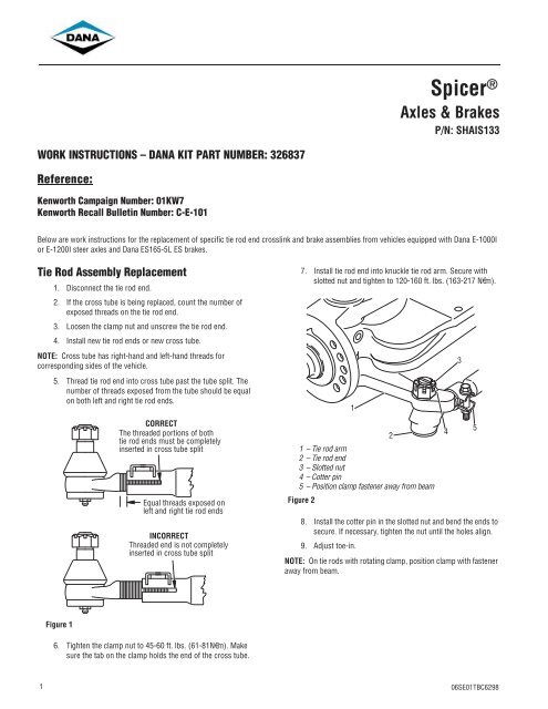
WORK INSTRUCTIONS <strong>–</strong> DANA KIT PART NUMBER: 326837<br />
Reference:<br />
Kenworth Campaign Number: 01KW7<br />
Kenworth Recall Bulletin Number: C-E-101<br />
1<br />
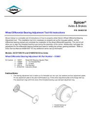
<strong>Spicer</strong> ®<br />
Axles & Brakes<br />
P/N: SHAIS133<br />
Below are <strong>work</strong> <strong>instructions</strong> for the replacement of specific tie rod end crosslink and brake assemblies from vehicles equipped with Dana E-1000I<br />
or E-1200I steer axles and Dana ES165-5L ES brakes.<br />
Tie Rod Assembly Replacement<br />
1. Disconnect the tie rod end.<br />
2. If the cross tube is being replaced, count the <strong>number</strong> of<br />
exposed threads on the tie rod end.<br />
3. Loosen the clamp nut and unscrew the tie rod end.<br />
4. Install new tie rod ends or new cross tube.<br />
NOTE: Cross tube has right-hand and left-hand threads for<br />
corresponding sides of the vehicle.<br />
5. Thread tie rod end into cross tube past the tube split. The<br />
<strong>number</strong> of threads exposed from the tube should be equal<br />
on both left and right tie rod ends.<br />
Figure 1<br />
CORRECT<br />
The threaded portions of both<br />
tie rod ends must be completely<br />
inserted in cross tube split<br />
Equal threads exposed on<br />
left and right tie rod ends<br />
INCORRECT<br />
Threaded end is not completely<br />
inserted in cross tube split<br />
6. Tighten the clamp nut to 45-60 ft. lbs. (61-81N€m). Make<br />
sure the tab on the clamp holds the end of the cross tube.<br />
7. Install tie rod end into knuckle tie rod arm. Secure with<br />
slotted nut and tighten to 120-160 ft. lbs. (163-217 N€m).<br />
1<br />
1 <strong>–</strong> Tie rod arm<br />
2 <strong>–</strong> Tie rod end<br />
3 <strong>–</strong> Slotted nut<br />
4<strong>–</strong> Cotter pin<br />
5 <strong>–</strong> Position clamp fastener away from beam<br />
Figure 2<br />
2<br />
8. Install the cotter pin in the slotted nut and bend the ends to<br />
secure. If necessary, tighten the nut until the holes align.<br />
9. Adjust toe-in.<br />
NOTE: On tie rods with rotating clamp, position clamp with fastener<br />
away from beam.<br />
4<br />
3<br />
5<br />
06SE01TBC6298
General Information<br />
While Dana does not offer asbestos brake linings, the long-term<br />
effects of some non-asbestos fibers have not been determined.<br />
Current OSHA Regulations cover exposure levels to some<br />
components of non-asbestos linings but not all. The following<br />
precautions must be used when handling these materials.<br />
1. AVOID CREATING DUST. Compressed air or dry brushing<br />
must never be used for cleaning brake assemblies or the<br />
<strong>work</strong> area.<br />
2. DANA RECOMMENDS THAT WORKERS DOING BRAKE<br />
WORK MUST TAKE STEPS TO MINIMIZE EXPOSURE TO<br />
AIRBORNE BRAKE LINING PARTICLES. Proper procedures<br />
to reduce exposure include <strong>work</strong>ing in a well ventilated<br />
area, segregation of areas where brake <strong>work</strong> is done, use<br />
of local filtered ventilation systems or use of enclosed cells<br />
with filtered vacuums. Respirators approved by the Mine<br />
Safety and Health Administration (MSHA) or National<br />
Institute for Occupational Safety and Health (NIOSH)<br />
should be worn at all times during brake servicing.<br />
3. Workers must wash before eating, drinking or smoking;<br />
shower after <strong>work</strong>ing, and should not wear <strong>work</strong> clothes<br />
home. Work clothes should be vacuumed and laundered<br />
separately without shaking.<br />
4. OSHA Regulations regarding testing, disposal of waste and<br />
methods of reducing exposure for asbestos are set forth in<br />
29 Code of Federal Regulations §1910.001. These<br />
Regulations provide valuable information which can be<br />
utilized to reduce exposure to airborne <strong>part</strong>icles.<br />
5. Material safety data sheets on this product, as required by<br />
OSHA, are available from Dana.<br />
2<br />
!<br />
DANGER: Avoid creating dust possible cancer and lung<br />
disease hazard<br />
Brake Maintenance Preliminary Steps<br />
Prior to performing any maintenance requiring removal of the tire<br />
and wheel, the following preliminary steps must be taken to ensure<br />
your safety. Refer to Figure 3.<br />
Figure 3<br />
! WARNING: Never <strong>work</strong> under a vehicle supported by a<br />
Block Wheels<br />
Support On<br />
Jack Stands<br />
of Adequate<br />
Capacity<br />
1. Set parking brake and block wheels to prevent vehicle<br />
movement.<br />
2. Raise drive axle with a jack and support on suitable stands.<br />
jack.<br />
3. Cage spring-type brake chamber following vehicle<br />
manufacturer’s <strong>instructions</strong>.<br />
06SE01TBC6298
Removal/Disassembly<br />
Drum Removal<br />
1. Perform “Brake Maintenance Preliminary Steps”.<br />
2. While depressing locking sleeve, back off brake adjuster<br />
adjustment nut on manual brake adjusters. Refer to<br />
Figure 4. Continue turning until shoes are fully returned to<br />
released position and clear of drum. On self adjusting<br />
brake adjusters, follow manufacturer’s <strong>instructions</strong>.<br />
NOTE: With outboard mounted drums go to step 6.<br />
! WARNING: Do not strike the axle shaft flange with a<br />
!<br />
Turn Adjuster Nut to<br />
Back-Off Adjustment<br />
Figure 4<br />
3. On drive axles, remove stud nuts and axle shafts. If used,<br />
remove Iockwashers and taper dowels. If necessary,<br />
loosen dowels by holding a brass drift in the center of the<br />
shaft head and striking it a sharp blow with a hammer. On<br />
trailer and steer axles, remove hub cap.<br />
hammer. Do not use chisels or wedges to loosen shaft or<br />
dowels.<br />
4. Remove axle spindle nut(s) and washer.<br />
5. While rocking drum, pull outboard enough to allow<br />
removal of outer wheel bearing.<br />
6. Remove drum by pulling outboard while rocking from side<br />
to side. If shoes are not clear of drum, return to Step 2<br />
above.<br />
CAUTION: If difficulty is found on removal, do not force<br />
drum. Excessive pulling force may damage brake<br />
components.<br />
06SE01TBC6298<br />
3
Brake Shoe Removal<br />
EB models (except EB-150-4L)/ ES-165-5D,L / ES-165-6D,L /<br />
ES-165-7D, F, L / ES-150-8D, F / ES-150-4D / ES-150-6D /<br />
ES-165-8D, F, L<br />
1. Perform steps in Removal/Disassembly: Drum Removal.<br />
2. ES-165-5,6,7,8,D,L,F, ES-150-4D, ES-150-8D, F & 6D<br />
ONLY: Pry roller retainer coiled loops out of both shoe web<br />
holes as shown in Figure 5. Pivot roller retainer to swing<br />
loops clear of shoe webs.<br />
NOTE: EB models do not have roller retainers.<br />
Figure 5<br />
4<br />
! WARNING: The long term effects of non-asbestos fibers<br />
Shoe<br />
Web<br />
Disengage<br />
Retainer Coiled<br />
Loops From<br />
Shoe Webs<br />
Roller<br />
Retainer<br />
Pivot Retainer to<br />
Swing Loops Clear<br />
of Shoe Web<br />
have not been determined. Therefore, precautions should<br />
be used when handling these materials.<br />
See General Information / Lining Material Warning<br />
Figure 6<br />
3. Using a large screwdriver or lever, lift upper shoe to stretch<br />
return spring as shown in Figure 6.<br />
4. Remove upper cam roller and pin.<br />
Lift Upper Shoe<br />
to Stretch Spring<br />
Remove Roller and Pin, Then<br />
Repeat for Lower Shoe.<br />
For ES Brakes, See Note Below<br />
NOTE: ES-165-5,6,7,8D, L, F, ES-150-4D, ES-150-8D, F & 6D<br />
ONLY: Remove roller and roller retainer as a unit.<br />
5. Repeat Steps 2 through 4 to remove lower shoe roller and<br />
pin.<br />
NOTE: Dana recommends the use of a suitable brake tool when<br />
removing rollers and return springs.<br />
06SE01TBC6298
6. Push cam end of both shoes toward cam and unhook shoe<br />
return spring. Remove and discard spring.<br />
NOTE: To remove return spring, position a lever or suitable tool<br />
with notch to engage spring rod. Refer to Figure 7. Apply downward<br />
force to stretch spring, allowing removal of upper spring hook.<br />
Remove and discard spring.<br />
Figure 7<br />
NOTE: ES-165-5,6,7L,D/ES-150-6D steer axle brakes may use two<br />
return springs with a horse collar or dual spring post. To remove<br />
return springs, position a lever or suitable tool with notch to engage<br />
spring. Return to Figure 7. Apply downward force to stretch upper<br />
spring, allowing removal of upper spring hook. Remove and<br />
discard. Repeat procedure for lower spring.<br />
06SE01TBC6298<br />
Stretch Using Suitable<br />
Tool Positioned<br />
As Shown<br />
7. Rotate both shoes around anchor pin and remove from<br />
vehicle. Refer to Figure 8.<br />
8. Clean and inspect remaining <strong>part</strong>s as outlined in removal/<br />
disassembly section of this manual.<br />
Figure 8<br />
Figure 9<br />
Rotate Both Shoes<br />
Around Anchor<br />
Pin and Lift Off<br />
Brake Shoes<br />
5
Installation/Assembly<br />
Brake Shoe Installation and Adjustments<br />
All EB (except EB-150-4L) and ES-165 5/6/7/8D, F, L<br />
NOTE: The following procedures are divided into sections,<br />
identified by brake model <strong>number</strong>s.<br />
6<br />
!<br />
1. See Inspection & Repair / Replacement to verify that<br />
spider camshaft, bracket, and brake adjuster are<br />
serviceable and properly installed.<br />
2. During shoe installation, lubricate:<br />
• Shoe roller recess - one-piece roller.<br />
• Roller I.D. - two-piece roller.<br />
CAUTION: Use only grease conforming to NLGI grade #1,<br />
high-temperature, waterproof.<br />
Do Not Lubricate:<br />
• Cam head surface. For efficient operation, this surface<br />
must remain free of oil, grease or other contaminants.<br />
3. Hook ends of new retainer springs into holes in both shoe<br />
tables, hooks pointing out.<br />
4. Position upper and lower shoes around anchor pin. Refer<br />
to Figure 10.<br />
! WARNING: The long term effects of non-asbestos fibers,<br />
have not been determined. Therefore, precautions should<br />
be used when handling these materials.<br />
See General Information / Lining Material Warning<br />
5. Install a new shoe return spring. Refer to Figure 11.<br />
NOTE: On ES-165-D, 1, F, a lever may be required to assist in<br />
hooking shoe return spring.<br />
With Retainer Springs<br />
Installed, Position<br />
Upper and Lower Shoes<br />
Around Anchor Pin<br />
Figure 10<br />
Figure 11<br />
ES-165-D,L,F Only:<br />
Stetch Spring Using Suitable<br />
Tool Positioned as Shown<br />
06SE01TBC6298
6. For ES-165 5/6/7/8D, L, F, ES-150-4D, ES-150-8D, F & 6D<br />
only:<br />
Assemble roller retainer on ends of roller as shown in Figure 12.<br />
Install Retainer<br />
on Roller<br />
Figure 12<br />
7. Using a lever or large screwdriver, stretch shoe return<br />
spring to allow insertion of new pin and roller, (or roller<br />
and retainer assembly) on the lower shoe web. Refer to<br />
Figure 13.<br />
NOTE: If drums are oversized, use oversize rollers, see Inspection-<br />
Drum Inspection.<br />
Figure 13<br />
06SE01TBC6298<br />
Stretch<br />
Return Spring,<br />
Install Roller<br />
And Retainer<br />
8. For ES-165 5/6/7/8D, L, F, ES-150-4D, ES-150-8D, F &<br />
6D only:<br />
Position assembly in roller recess as shown. Squeeze loops and<br />
swing retainer into position to snap loops into web holes. Refer to<br />
Figure 14. Verify that both retainer loops are engaged in web holes<br />
before proceeding.<br />
Figure 14<br />
Web<br />
Hole<br />
9. Repeat process on upper shoe.<br />
Install Retainer<br />
Loops in Shoe<br />
Web Holes<br />
NOTE: For all EB Models a roller retainer is not used.<br />
7
Brake Adjustment - Manual Brake Adjuster<br />
NOTE: An assistant is required to make a brake adjustment.<br />
To determine whether Dana Brakes require adjustment, applied<br />
stroke is measured and compared to the maximum value for the air<br />
chamber size in use on the vehicle.<br />
1. Perform “Brake Maintenance Preliminary Steps”<br />
described earlier.<br />
2. With air chamber pushrod fully retracted, measure<br />
distance from face of air chamber to centerline of clevis pin<br />
hole. Refer to Figure 15. If the measurement is not within<br />
ranges shown in Table 1, reposition clevis. Remeasure the<br />
distance and repeat until within range. Record exact<br />
measured distance as dimension “A”.<br />
8<br />
! WARNING: Block all wheels before beginning this<br />
Table 1<br />
adjustment procedure<br />
Distance: Clevis Pin Hole<br />
Centerline to Air Chamber Face<br />
All brakes (except Mack and<br />
Trailer Axle)<br />
2-5/8” ± 1/16”<br />
(66.7 ± 1.59 mm)<br />
Mack brakes 4-3/8” ± 1/16”<br />
(111.1 ± 1.59 mm)<br />
Trailer Axle brakes 6-1/2” ± 1/8”<br />
(165.1 ± 3.175 mm)<br />
Figure 14<br />
A<br />
<br />
<br />
<br />
<br />
3. Apply and hold an 80 psi brake application, and again<br />
measure from face of air chamber to clevis pin centerline.<br />
Refer to Figure 16. Record distance as dimension “B”.<br />
Figure 15<br />
Table 2<br />
4. Subtract dimension “A” from “B”. The difference is applied<br />
stroke. Compare applied stroke to maximum value in<br />
Table 2. If applied stroke equals or exceeds maximum<br />
applied stroke shown, adjust brakes. If less than the<br />
maximum, no adjustment is required and you may perform<br />
Brake Operation Check.<br />
80 - 90 PSI<br />
Air Chamber Size Maximum<br />
Applied<br />
Stroke<br />
Type 30” Long Stroke<br />
Type 30”<br />
Type 24”<br />
Type 24” (with 2-1/2”<br />
extended stroke)<br />
Type 24 (with 3”<br />
extended stroke)<br />
B<br />
2.5”<br />
2”<br />
1-3/4”<br />
2”<br />
2.5”<br />
Measure This<br />
Distance<br />
at 80 psi,<br />
Dimension B<br />
Desired Free<br />
Stroke<br />
3/8” to 5/8”<br />
(Without Drag)<br />
Type 20” and 16” 1-3/4” 3/8” to 1/2”<br />
Type 12” 1-3/8” 3/8” to 1/2”<br />
NOTE: If adjustment is necessary, Dana Brakes are adjusted to<br />
achieve proper free stroke. The difference between free stroke and<br />
applied stroke is merely the method used to move the brake adjuster<br />
from rest. Applied stroke uses an 80 psi brake application; free<br />
stroke is measured using a lever to move the brake adjuster until the<br />
brake shoes contact the drum. If applied stroke exceeded the<br />
maximum and adjustment is necessary, adjust the brakes as<br />
described in steps 5 through 8 below.<br />
06SE01TBC6298
5. Take “A” dimension exactly as before. Take “B”<br />
measurement using a lever to move brake adjuster as<br />
shown until the shoes contact drum. Refer to Figure 17.<br />
The result of “B” - “A” is brake free stroke. Adjust free<br />
stroke to within range specified in Table 2.<br />
Figure 16<br />
6. To adjust free stroke, depress locking sleeve on brake<br />
adjuster adjustment nut and turn in direction required.<br />
Recheck free stroke to verify it is within range. Make sure<br />
sleeve is “locked” when adjustment is completed.<br />
7. Verify that brakes are not dragging by spinning wheels by<br />
hand or tapping drum lightly with a hammer and listening<br />
for a sharp ringing sound.<br />
8. Perform Brake Operation Check, to verify proper<br />
operation of brakes before releasing vehicle for service.<br />
06SE01TBC6298<br />
Lever<br />
B<br />
Measure with<br />
Brake Applied<br />
Using Lever,<br />
Dimension B<br />
Brake Adjustment - Self Adjusting Brake<br />
Adjuster<br />
1. Brake adjustment for self adjusting brake adjusters is the<br />
same as for manual brake adjusters.<br />
2. Refer to the Self Adjusting Brake Adjuster Manufacturer’s<br />
Instructions for proper installation.<br />
Brake Operation Check<br />
NOTE: An assistant is required to make a thorough brake operation<br />
check.<br />
!<br />
1. Apply brakes to 80 psi and hold. Check all air line fittings<br />
and air chambers for leakage.<br />
2. Apply and release brakes while observing operation of<br />
brake adjusters on each axle. As brakes are applied and<br />
released, brake adjusters should move in unison visually.<br />
3. Investigate source and make corrections for any<br />
discrepancies found in Steps 1 and 2.<br />
4. Drive vehicle at low speeds in a safe area and make several<br />
brake applications to verify safe operation and absence of<br />
pulling, grabbing, or noise. If any of these are noted,<br />
investigate and repair prior to releasing vehicle for service.<br />
CAUTION: Never release a vehicle for service if any brake<br />
discrepancy - no matter how minor - is evident.<br />
9
For spec’ing or service assistance, call 1-800- 24 hours a day, 7 days a week, for more time on the road.<br />
Or visit our web site at http://www..com.<br />
SHAIS133A September 2001 Copyright Dana Corporation, 2001 Dana Corporation<br />
Printed in U.S.A. All Rights Reserved Commercial Vehicle Axle Division<br />
www.<strong>dana</strong>.com P.O. Box