work instructions – dana kit part number - Spicer
work instructions – dana kit part number - Spicer
work instructions – dana kit part number - Spicer

You also want an ePaper? Increase the reach of your titles
YUMPU automatically turns print PDFs into web optimized ePapers that Google loves.
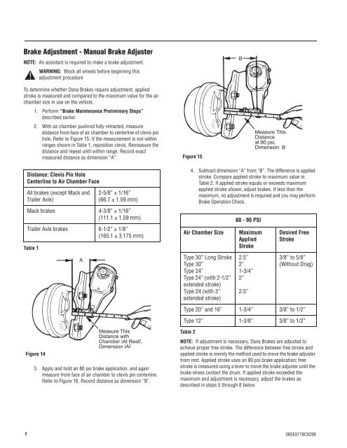
Brake Adjustment - Manual Brake Adjuster<br />
NOTE: An assistant is required to make a brake adjustment.<br />
To determine whether Dana Brakes require adjustment, applied<br />
stroke is measured and compared to the maximum value for the air<br />
chamber size in use on the vehicle.<br />
1. Perform “Brake Maintenance Preliminary Steps”<br />
described earlier.<br />
2. With air chamber pushrod fully retracted, measure<br />
distance from face of air chamber to centerline of clevis pin<br />
hole. Refer to Figure 15. If the measurement is not within<br />
ranges shown in Table 1, reposition clevis. Remeasure the<br />
distance and repeat until within range. Record exact<br />
measured distance as dimension “A”.<br />
8<br />
! WARNING: Block all wheels before beginning this<br />
Table 1<br />
adjustment procedure<br />
Distance: Clevis Pin Hole<br />
Centerline to Air Chamber Face<br />
All brakes (except Mack and<br />
Trailer Axle)<br />
2-5/8” ± 1/16”<br />
(66.7 ± 1.59 mm)<br />
Mack brakes 4-3/8” ± 1/16”<br />
(111.1 ± 1.59 mm)<br />
Trailer Axle brakes 6-1/2” ± 1/8”<br />
(165.1 ± 3.175 mm)<br />
Figure 14<br />
A<br />
<br />
<br />
<br />
<br />
3. Apply and hold an 80 psi brake application, and again<br />
measure from face of air chamber to clevis pin centerline.<br />
Refer to Figure 16. Record distance as dimension “B”.<br />
Figure 15<br />
Table 2<br />
4. Subtract dimension “A” from “B”. The difference is applied<br />
stroke. Compare applied stroke to maximum value in<br />
Table 2. If applied stroke equals or exceeds maximum<br />
applied stroke shown, adjust brakes. If less than the<br />
maximum, no adjustment is required and you may perform<br />
Brake Operation Check.<br />
80 - 90 PSI<br />
Air Chamber Size Maximum<br />
Applied<br />
Stroke<br />
Type 30” Long Stroke<br />
Type 30”<br />
Type 24”<br />
Type 24” (with 2-1/2”<br />
extended stroke)<br />
Type 24 (with 3”<br />
extended stroke)<br />
B<br />
2.5”<br />
2”<br />
1-3/4”<br />
2”<br />
2.5”<br />
Measure This<br />
Distance<br />
at 80 psi,<br />
Dimension B<br />
Desired Free<br />
Stroke<br />
3/8” to 5/8”<br />
(Without Drag)<br />
Type 20” and 16” 1-3/4” 3/8” to 1/2”<br />
Type 12” 1-3/8” 3/8” to 1/2”<br />
NOTE: If adjustment is necessary, Dana Brakes are adjusted to<br />
achieve proper free stroke. The difference between free stroke and<br />
applied stroke is merely the method used to move the brake adjuster<br />
from rest. Applied stroke uses an 80 psi brake application; free<br />
stroke is measured using a lever to move the brake adjuster until the<br />
brake shoes contact the drum. If applied stroke exceeded the<br />
maximum and adjustment is necessary, adjust the brakes as<br />
described in steps 5 through 8 below.<br />
06SE01TBC6298