A Simplified Eigenstrain Approach - Department of Mechanical and ...
A Simplified Eigenstrain Approach - Department of Mechanical and ...
A Simplified Eigenstrain Approach - Department of Mechanical and ...

You also want an ePaper? Increase the reach of your titles
YUMPU automatically turns print PDFs into web optimized ePapers that Google loves.
2<br />
eigenstrain field is the combination <strong>of</strong> thermal, transformation, <strong>and</strong> plastic strains which are the<br />
net result <strong>of</strong> the welding process.<br />
Although residual stress is caused by eigenstrain, it is also a function <strong>of</strong> the geometry <strong>of</strong> the<br />
body in which it is imposed. For example, imagine a long welded plate. If a sample is removed<br />
from the plate that is short along the weld-length, stress will be released in removing the sample.<br />
The stress has changed, but the eigenstrain within the removed sample remains the same,<br />
assuming that the cutting process results only in elastic deformation <strong>of</strong> the sample. The<br />
eigenstrain method is a form <strong>of</strong> destructive sectioning, as strain released during geometry<br />
changes is used to deduce the underlying eigenstrain distribution. The eigenstrain distribution is<br />
complicated, however, since it represents the spatial variation <strong>of</strong> a tensor quantity. If the<br />
eigenstrain can be found, it can then be used to estimate residual stress in the original sample,<br />
prior to cutting, <strong>and</strong> also in the structure from which the sample was removed.<br />
Application <strong>of</strong> the eigenstrain approach to residual stress in continuously welded joints was<br />
presented by Ueda, et al. (1985) <strong>and</strong> further studied in a recent paper (Hill <strong>and</strong> Nelson, 1995).<br />
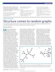
Consider a long, continuously welded plate with directions which correspond to the weld bead as<br />
shown in Figure 1. These consist <strong>of</strong> the transverse, perpendicular, <strong>and</strong> longitudinal directions<br />
relative to the direction <strong>of</strong> welding. We have chosen corresponding coordinates x,<br />
y,<br />
<strong>and</strong> z,<br />
respectively. The assumption <strong>of</strong> continuous welding allows consideration <strong>of</strong> an eigenstrain field<br />
that is dependent on the transverse <strong>and</strong> perpendicular coordinates, while independent <strong>of</strong> the<br />
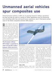
longitudinal coordinate. The basis for this assumption is that each plane in the weld<br />
cross-section, like the two shaded in Figure 2, is thought to experience the same thermal <strong>and</strong><br />
mechanical processes during a continuous weld pass. This assumption holds neither in the<br />
thermal nor the mechanical sense near the ends <strong>of</strong> the joint, but the assumption may be<br />
reasonable in the remainder <strong>of</strong> the joint, as indicated by experimental evidence presented by Hill<br />
<strong>and</strong> Nelson (1996).<br />
Long. (z)<br />
Perp. (y)<br />
Trans. (x)<br />
Figure 1 – Directions relative to a weld.<br />
Long. (z)<br />
Perp. (y)<br />
Trans. (x)<br />
Figure 2 – Two planes which have the same<br />
eigenstrain distribution.<br />
An illustration <strong>of</strong> Ueda’s technique is shown in Figure 3. A sample <strong>of</strong> welded plate, obtained<br />
from the structure <strong>of</strong> interest, is instrumented with an array <strong>of</strong> strain gages on one <strong>of</strong> its faces<br />
normal to the z-axis<br />
(shaded in the figure). Two strain-relaxation measurements are then<br />
performed, one from block to thin slice <strong>and</strong> the other from slice to small pieces (dice), each<br />
containing a strain gage. Since the slice is in plane stress, slice-to-dice data allow determination<br />
<strong>of</strong> the x-y distribution <strong>of</strong> the eigenstrain components in the transverse-perpendicular plane ( ε* xx ,<br />
ε* yy , <strong>and</strong> ε* xy ). Using these results with the block-to-slice relaxation data allows determination<br />
<strong>of</strong> the eigenstrain component associated with the longitudinal direction ( ε* zz ). The two<br />
additional components <strong>of</strong> eigenstrain ( ε* yz <strong>and</strong> ε* zx<br />
) are assumed to be zero because they<br />
would cause asymmetrical stresses to arise in the welded joint which is contrary to empirical<br />
observation (Ueda, et al., 1985). Ueda’s method, then, allows determination <strong>of</strong> the x-y