Temperature controller AVTB (PN 16) - Danfoss.com
Temperature controller AVTB (PN 16) - Danfoss.com
Temperature controller AVTB (PN 16) - Danfoss.com

Create successful ePaper yourself
Turn your PDF publications into a flip-book with our unique Google optimized e-Paper software.
Data sheet<br />
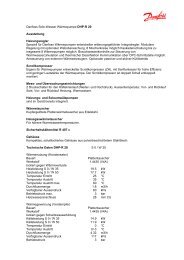
<strong>Temperature</strong> <strong>controller</strong> <strong>AVTB</strong> (<strong>PN</strong> <strong>16</strong>)<br />
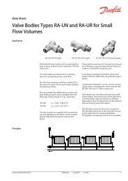
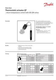
Description <strong>AVTB</strong> is self-acting temperature <strong>controller</strong> used<br />
to control the water temperature in hot water<br />
tanks, heat exchangers, oil preheaters, etc.<br />
Controller closes on rising temperature.<br />
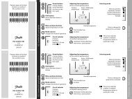
Ordering<br />
1) Complete <strong>controller</strong> including sensor<br />
stuffing box. The immersion pocket is<br />
an accessory.<br />
2) Including small sensor Ø 9.5 × 180.<br />
The sensor is to be mounted where<br />
the system temperature is warmer<br />
than the temperature in the valve<br />
housing. Insulaton disk is factory<br />
mounted on the <strong>controller</strong>.<br />
3) Including small sensor Ø 9.5 × 150.<br />
Capillary tube length 2.3 m.<br />
4) Including sensor Ø 18 × 210;<br />
available on request<br />
Example:<br />
<strong>Temperature</strong> <strong>controller</strong>, DN 15,<br />
k VS 1.9, <strong>PN</strong> <strong>16</strong>, setting range<br />
30 … 100 °C, t max 130 °C, ext. thread<br />
- 1× <strong>AVTB</strong> DN 15 Controller<br />
Code No: 003N5141<br />
Option:<br />
- 1× Imm. pocket, brass<br />
Code No: 013U0290<br />
- 1× Weld-on taipieces<br />
Code No: 003H6908<br />
<strong>AVTB</strong> Controller<br />
Picture DN<br />
15<br />
20<br />
25<br />
Capillary tube length: 2 m.<br />
Accessories<br />
Setting<br />
range<br />
The <strong>controller</strong> has a control valve, thermostatic<br />
actuator and handle for temperature setting.<br />
Thermostatic actuator consist of a bellows,<br />
capillary tube and sensor.<br />
Main data:<br />
• DN 15, 20, 25<br />
• k VS 1.9, 3.4, 5.5 m 3 /h<br />
• <strong>PN</strong> <strong>16</strong><br />
• Setting range: 0…30 °C / 20…60 °C / 30…100 °C<br />
• <strong>Temperature</strong>:<br />
- Circulation water / glycolic water up to 30%:<br />
-25 … +130 °C<br />
• Connections:<br />
- Int. thread<br />
- Ext. thread (weld-on and ext. thread tailpieces)<br />
• Flow or return mounting, depending on<br />
sensor type.<br />
DH-SMT/SI VD.JK.Z2.02 © <strong>Danfoss</strong> 11/2006 1<br />
k VS<br />
(°C) (m 3 /h)<br />
Max.<br />
sensor<br />
temp.<br />
(°C)<br />
Internal thread External thread<br />
Connection<br />
ISO 7/1<br />
Code No. 1)<br />
Connection<br />
ISO 228/1<br />
Code No. 1)<br />
0 … 30<br />
55<br />
003N2232<br />
1.9<br />
Rp ½<br />
4)<br />
003N5101<br />
G ¾ A<br />
4)<br />
20 … 60 90 003N82292) 003N5114 2)<br />
30 … 100 130 003N8141 3) 003N5141 3)<br />
0 … 30<br />
55<br />
003N3232<br />
3.4<br />
Rp ¾<br />
4)<br />
003N5102<br />
G 1 A<br />
4)<br />
20 … 60 90 003N82302) 003N5115 2)<br />
30 … 100 130 003N8142 3) 003N51423) 0 … 30<br />
55<br />
003N4232 4)<br />
003N5103 4)<br />
20 … 60 5.5 90 Rp 1 003N8253 G 1¼ A<br />
2) 003N51<strong>16</strong> 2)<br />
30 … 100 130 003N8143 3) 003N5143 3)<br />
Picture Type designations DN Connection Code No.<br />
15<br />
003H6908<br />
Weld-on taipieces<br />
20 -<br />
003H6909<br />
25 003H6910<br />
External thread taipieces<br />
15<br />
20<br />
25<br />
Con. ext. thread acc. to<br />
EN 10226-1<br />
R ½”<br />
R ¾”<br />
R 1”<br />
003H6902<br />
003H6903<br />
003H6904<br />
Rp ½ × M14 × 1 mm, brass 182 mm, without sens.stuff. box 013U0290<br />
Immersion pocket<br />
Rp ½ × M18 × 1,5 mm, st. steel 182 mm, with sens.stuff. box<br />
Rp ¾ × M22 × 1 mm, brass 220 mm, with sens.stuff. box<br />
003N0196<br />
003N0050<br />
Rp ¾ × M22 × 1 mm, st. steel 220 mm, with sens.stuff. box 003N0192<br />
Insulation disk 1) 003N4022<br />
1) For details see “Installation positions” section
Data sheet <strong>Temperature</strong> <strong>controller</strong> <strong>AVTB</strong> (<strong>PN</strong> <strong>16</strong>)<br />
Ordering (continuous) Service kits<br />
Picture Type designation for Code No.<br />
Repair set<br />
Two diaphragms, two O-rings, one rubber cone,<br />
one tube of grease and eight valve cover screws<br />
DN 15 003N4006<br />
DN 20 003N4007<br />
DN 25 003N4008<br />
Thermostatic actuator 0 … 30 °C, sensor Ø 18 × 210, 2m 003N0075<br />
Thermostatic actuator 20 … 60 °C, sensor Ø 9.5 × 180, 2m 003N0130<br />
Thermostatic actuator 30 … 100 °C, sensor Ø 9.5 × 150, 2.3m 003N0131<br />
Housing of sensor stuffing box, R ½ × M14 × 1 mm, rubber EPDM Ø 12.6 × 4 × 6 mm 013U8102 1)<br />
1) For thermostatic actuators 20 ... 60°C and 30 ... 100°C; code includes housing and gasket of sensor stuffing box<br />
Technical data Nominal diameter DN 15 20 25<br />
k VS value m 3 /h 1.9 3.4 5.5<br />
Cavitation factor z 0.4<br />
Nominal pressure <strong>PN</strong> <strong>16</strong><br />
Max. differential pressure bar 10<br />
Application principle<br />
Medium Circulation water / glycolic water up to 30%<br />
Medium pH Min. 7, max. 10<br />
Medium temperature oC -25 … +130<br />
Connections<br />
Materials<br />
valve<br />
tailpieces<br />
Internal and external thread<br />
Weld-on and external thread<br />
Valve body<br />
internal thread<br />
external thread<br />
MS 58, hot-pressed, DIN 17660, W.No. 2.0402, CuZn40Pb2<br />
Dezincing-free brass, BS 2872/CZ132<br />
Valve seat Cr Ni steel, DIN 17440, W.No. 1.4301<br />
Valve cone NBR-rubber<br />
Spindle Dezincing-free brass, BS 2872/CZ132<br />
Other metal parts Dezincing-free brass, BS 2874/CZ132<br />
Diaphragms, O-rings EPDM-rubber<br />
<strong>Temperature</strong> sensor Copper<br />
0 … 30<br />
Sensor charge<br />
oC R 152 A, C2H4F2<br />
20 … 60 oC Butane R600, C4H10<br />
30 … 100 oC Carbon dioxide, CO2<br />
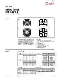
Slow control system, setting range 30 …100 °C<br />
Fast control system, setting range 0 … 30 °C/20 … 60 °C<br />
2 VD.JK.Z2.02 © <strong>Danfoss</strong> 11/2006 DH-SMT/SI
Data sheet <strong>Temperature</strong> <strong>controller</strong> <strong>AVTB</strong> (<strong>PN</strong> <strong>16</strong>)<br />
Installation positions <strong>Temperature</strong> <strong>controller</strong><br />
The <strong>controller</strong> can be installed in any position,<br />
with flow in the direction of the cast-in arrow.<br />
Sizing<br />
<strong>AVTB</strong> 20 … 60 must always be installed in the<br />
return line (sensor warmer than valve).<br />
If <strong>AVTB</strong> 20 … 60 has been installed in the return<br />
line from a service water heat exchanger (where<br />
for certain periods the return temperature<br />
approaches the sensor temperature) the<br />
installation of insulation disk is re<strong>com</strong>mended<br />
(003N4022). Insulation disk is factory<br />
mounted on the product.<br />
<strong>Temperature</strong> sensor<br />
<strong>AVTB</strong> 0 … 30 and 30 …100 can be installed either<br />
in flow or in return line.<br />
With <strong>AVTB</strong> 30 … 100, if temperature variations<br />
of more than 20 °C occur at the valve, insulation<br />
disk (003N4022) must be installed between<br />
thermostatic actuator and valve body.<br />
Sensor Ø 18 × 210 mm 2) Sensor Ø 9.5 × 180 mm 1) Sensor Ø 9.5 × 150 mm 2)<br />
(<strong>AVTB</strong> 0 … 30 °C) (<strong>AVTB</strong> 20 … 60 °C) (<strong>AVTB</strong> 30 … 100 °C)<br />
1) The sensor is to be mounted where the system temperature is warmer than the temperature in the valve body<br />
2) The sensor can be mounted where the system temperature is either warmer or colder than the temperature in the valve body<br />
DH-SMT/SI VD.JK.Z2.02 © <strong>Danfoss</strong> 11/2006 3
Data sheet <strong>Temperature</strong> <strong>controller</strong> <strong>AVTB</strong> (<strong>PN</strong> <strong>16</strong>)<br />
Sizing (continuous) Example<br />
<strong>Temperature</strong> range and P-band<br />
Hot water temperature control in hot water<br />
tanks.<br />
Primary medium: Water<br />
Given:<br />
Calculated kv value is 1 m<br />
Load:<br />
Primary temperature<br />
drop Δt:<br />
31 kW (26500 kcal/h)<br />
20 K<br />
Differential pressure<br />
Δp across the valve: 1.7 bar<br />
Max. hot water<br />
temperature:<br />
Water volume Q:<br />
Required:<br />
The correct valve size<br />
55 °C<br />
31 0.86<br />
3<br />
1.3m<br />
20<br />
h<br />
3 /h.<br />
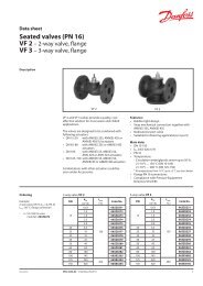
From this value on the kV scale in the <strong>AVTB</strong><br />
diagram, take a line horizontally to intersect<br />
the columns for re<strong>com</strong>mended sizing range.<br />
Select the smallest possible valve, here an <strong>AVTB</strong><br />
15. A temperature range of 30 …100 °C can be<br />
assumed as suitable for this example.<br />
The P-band (XP) and final temperature range<br />
can also be read from the <strong>AVTB</strong> diagram. The<br />
required closing temperature can be read from<br />
the scale for the valve selected. However, there<br />
are two temperature ranges that meet the<br />
requirement for a closing temperature of 55 °C.<br />
XP is 9 K for the range 30 …100 °C, which means<br />
that the <strong>controller</strong> will yield the calculated<br />
capacity at a sensor temperature of 55 °C minus<br />
9 K = 46 °C. For the range 20 … 60 °C XP = 4 K.<br />
This means that the <strong>controller</strong> will yield the<br />
calculated capacity at 55 °C minus 4 K = 51 °C.<br />
Q 1.<br />
3<br />
k v <br />
1.0<br />
m<br />
p<br />
1.7<br />
Note: The values stated are mean values<br />
3<br />
h<br />
To ensure the most stable control an <strong>AVTB</strong> 15<br />
with a range 30 … 100 °C should be chosen. The<br />
water in the hot water tank will reach the closing<br />
temperature (55 °C) only when there has been no<br />
hot water demand for some time.<br />
<strong>AVTB</strong> 0 … 30 °C <strong>AVTB</strong> 30 … 100 °C<br />
<strong>AVTB</strong> 20 … 60 °C<br />
<strong>AVTB</strong> diagram to determine valve size, temperature range and proportional band (X P ).<br />
4 VD.JK.Z2.02 © <strong>Danfoss</strong> 11/2006 DH-SMT/SI
Data sheet <strong>Temperature</strong> <strong>controller</strong> <strong>AVTB</strong> (<strong>PN</strong> <strong>16</strong>)<br />
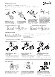
Design<br />
1. Handle for temperature<br />
setting<br />
2. Spring housing<br />
3. Setting spring<br />
4. O-ring<br />
5. Diaphragm<br />
6. Spindle<br />
7. Valve body<br />
8. Valve cone<br />
9. Bellows<br />
10. Bellows stop<br />
11. Pressure stem<br />
12. <strong>Temperature</strong> sensor<br />
13. Sensor stuffing box<br />
15<br />
14. Housing of sensor stuffing box<br />
15. Gasket of sensor stuffing box<br />
13<br />
14<br />
<strong>16</strong>. Sealing bolt of sensor<br />
stuffing box <strong>16</strong><br />
Settings <strong>Temperature</strong> setting<br />
Relation between scale numbers 1-5 and the<br />
closing temperature.<br />
The values given are approximate.<br />
Scale setting 1 2 3 4 5<br />
C losing temperature<br />
(0 … 30 °C) 0 3 15 23 30 °C<br />
(20 … 60 °C) 20 35 50 60 70<br />
(30 … 100 °C) 30 35 55 75 95 120<br />
DH-SMT/SI VD.JK.Z2.02 © <strong>Danfoss</strong> 11/2006 5
Data sheet <strong>Temperature</strong> <strong>controller</strong> <strong>AVTB</strong> (<strong>PN</strong> <strong>16</strong>)<br />
Dimensions<br />
Type<br />
<strong>AVTB</strong> with internal thread <strong>AVTB</strong> with external thread<br />
H 1<br />
mm<br />
H 2<br />
mm<br />
L<br />
mm<br />
6 VD.JK.Z2.02 © <strong>Danfoss</strong> 11/2006 DH-SMT/SI<br />
L 1<br />
mm<br />
L2<br />
mm<br />
L3<br />
mm<br />
L4<br />
mm<br />
a<br />
ISO 7/1<br />
(int. thread)<br />
b<br />
ISO 228/1<br />
(ext. thread)<br />
<strong>AVTB</strong> 15 217 133 72 14 141 149 75 R p ½ G ¾A<br />
<strong>AVTB</strong> 20 217 133 90 <strong>16</strong> 154 <strong>16</strong>4 80 R p ¾ G 1A<br />
<strong>AVTB</strong> 25 227 138 95 19 <strong>16</strong>8 <strong>16</strong>7 83 R p 1 G 1¼A<br />
Immersion pockets Sensor stuffing box<br />
Weld-on tailpieces External thread tailpieces<br />
G Ød L Weight<br />
(mm) (mm) (mm) (kg)<br />
15 15 35 0.18<br />
20 20 40 0.26<br />
25 27 40 0.38<br />
G R L Weight<br />
(“) (“) (mm) (kg)<br />
¾ ½ 25.5 0.17<br />
1 ¾ 27.5 0.27<br />
1 ¼ 1 32.5 0.45
Data sheet <strong>Temperature</strong> <strong>controller</strong> <strong>AVTB</strong> (<strong>PN</strong> <strong>16</strong>)<br />
DH-SMT/SI VD.JK.Z2.02 © <strong>Danfoss</strong> 11/2006 7
Data sheet <strong>Temperature</strong> <strong>controller</strong> <strong>AVTB</strong> (<strong>PN</strong> <strong>16</strong>)<br />
8 VD.JK.Z2.02 © <strong>Danfoss</strong> 11/2006 DH-SMT/SI