3-way control valves VK 3 - Danfoss.com
3-way control valves VK 3 - Danfoss.com
3-way control valves VK 3 - Danfoss.com

Create successful ePaper yourself
Turn your PDF publications into a flip-book with our unique Google optimized e-Paper software.
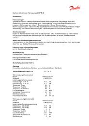
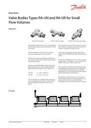
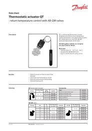
Data sheet<br />
3-<strong>way</strong> <strong>control</strong> <strong>valves</strong><br />
<strong>VK</strong> 3<br />
Description / Application<br />
Ordering<br />
Note:<br />
k vs - is the flow in m³/h of water at a<br />
temperature between 5 °C and 40 °C which<br />
passes through a valve open at the nominal<br />
stroke with 100 kPa (1 bar) pressure drop.<br />
Max. ∆p is the physical limit of differential<br />
pressure the valve will close against.<br />
The re<strong>com</strong>mended ∆p is based on the<br />
generation of noise, plug erosion etc. It should<br />
be checked against the ∆p figure calculated<br />
from the chart on page 3 or the equation<br />
below, with the valve fully opened at design<br />
flow rate.<br />
<strong>VK</strong> 3 <strong>valves</strong> are a range of 3 port high<br />
specification flanged <strong>valves</strong> for chilled water,<br />
LPHW, MPHW, HPHW (low, medium or high<br />
pressure hot water) steam and thermo oil<br />
applications. The cast iron body with stainless<br />
steel plug and seat is suitable for pressures<br />
up to 25 bar. These <strong>valves</strong> may be used with<br />
glycol concentrations of up to 50 % making<br />
them suitable for ice storage applications.<br />
Main data:<br />
Cast iron / stainless steel construction.<br />
Flanged connections DN 15 to 100 mm<br />
Suitable for water, steam or thermo oil<br />
Nominal pressure 25 bar<br />
Suitable for use with AMV(AME) 56 K or<br />
AMV(AME) 85 K and 86 K actuators.<br />
Suitable for use with ethylene and<br />
propylene glycol up to 50 % concentration.<br />
Compliance with PED directive 97/23/EC.<br />
Type DN (mm) k vs (m 3/ h) Stroke (mm) Re<strong>com</strong>. ∆p (bar) Code No.<br />
<strong>VK</strong>3 15/4.0 15 4.0 5.0 065Z3201<br />
<strong>VK</strong>3 20/6.3 20 6.3 5.0 065Z3202<br />
<strong>VK</strong>3 25/10<br />
<strong>VK</strong>3 32/16<br />
25<br />
32<br />
10<br />
16<br />
15<br />
5.0<br />
5.0<br />
065Z3203<br />
065Z3204<br />
<strong>VK</strong>3 40/25 40 25 5.0 065Z3205<br />
<strong>VK</strong>3 50/40 50 40 5.0 065Z3206<br />
<strong>VK</strong>3 65/63<br />
<strong>VK</strong>3 65/63*<br />
65 63<br />
4.5<br />
4.5<br />
065Z3207<br />
065Z3210<br />
<strong>VK</strong>3 80/100 80 100 35 3.0 065Z3208<br />
<strong>VK</strong>3 100/160<br />
<strong>VK</strong>3 100/160*<br />
100 160<br />
2.0<br />
2.0<br />
065Z3209<br />
065Z3211<br />
* designed for pipe system PN 16<br />
2<br />
⎛ Q ⎞<br />
ΔPvalve<br />
= S ⎜ ⎟<br />
⎜ k ⎟<br />
⎝ vs ⎠<br />
where S = specific gravity<br />
Q = flow rate in m 3 /h<br />
∆pvalve = pressure drop across the valve in bar<br />
(fully open).<br />
Conversion factors<br />
1 bar = 100 kPa = 14.5 psi<br />
1 l/s = 1 kg/s = 3.6 m 3 /h<br />
SIBC VD.HB.L1.02 © <strong>Danfoss</strong> 12/02 1
Data sheet 3-<strong>way</strong> <strong>control</strong> <strong>valves</strong> <strong>VK</strong> 3<br />
Technical data<br />
Design<br />
1. Stuffing box<br />
2. Valve cover<br />
3. Spindle with bellows<br />
4. Valve body<br />
5. Cone<br />
6. Valve supplementary<br />
Pressure stage PN 25<br />
Control range linear<br />
Media Circulation water / Thermo oil / Glycolic water up to 50 % /<br />
Steam up to 6 bar max.<br />
Leakage loss 0.05 % of kvs Medium temperature 2 - 350 °C<br />
Stroke 15 mm (DN 15 - 50); 35 mm (DN 65 - 100)<br />
Material<br />
Connection Flanged ISO 7005-2<br />
Maximum working pressure<br />
AB<br />
Disposal The valve must be dismantled and the<br />
elements sorted into various material groups<br />
before disposal.<br />
B<br />
Body: Ductile iron EN-GJS-400-18-LT (GGG 40.3)<br />
Valve seat: Stainless steel<br />
Cone: Stainless steel<br />
Stem: Stainless steel<br />
Stuffing box: PTFE<br />
2 VD.HB.L1.02 © <strong>Danfoss</strong> 12/02 SIBC<br />
A
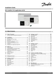
Data sheet 3-<strong>way</strong> <strong>control</strong> <strong>valves</strong> <strong>VK</strong> 3<br />
Installation<br />
Hydraulic connections<br />
Mount according to flow direction as indicated<br />
on valve body, AB is al<strong>way</strong>s the outlet port;<br />
inlets are A (two port) or A and B (three port).<br />
Valve Mounting<br />
Before mounting the valve be sure that the<br />
pipes are clean and free from swarf. It is<br />
essential that the pipes are lined up squarely<br />
with the valve at each connection and that<br />
they are free from vibrations.<br />
Install the motorized <strong>control</strong> valve with the<br />
actuator in a horizontal or vertical position but<br />
not upside down (at high temperatures the<br />
horizontal position is preferred).<br />
Leave sufficient clearance to facilitate the<br />
dismantling of the actuator from the valve<br />
body for maintenance purposes.<br />
The valve must not be installed in an<br />
explosive atmosphere or at an ambient<br />
temperature higher than 50 °C or lower than<br />
0 °C. It must not be subject to steam jets,<br />
water jets or dripping liquid.<br />
Note that the actuator may be rotated up<br />
to 360° with respect to the valve body, by<br />
loosening the retaining fixture. After this<br />
operation retighten.<br />
SIBC VD.HB.L1.02 © <strong>Danfoss</strong> 12/02 3
Data sheet 3-<strong>way</strong> <strong>control</strong> <strong>valves</strong> <strong>VK</strong> 3<br />
Control valve sizing diagram for fluids<br />
4 VD.HB.L1.02 © <strong>Danfoss</strong> 12/02 SIBC
Data sheet 3-<strong>way</strong> <strong>control</strong> <strong>valves</strong> <strong>VK</strong> 3<br />
Control valve sizing<br />
diagram for fluids<br />
Example:<br />
1 For fluids with specific gravity of 1<br />
(e.g. water)<br />
Design data:<br />
Flow rate: 6 m3 /h<br />
System pressure drop: 55 kPa<br />
Locate the horizontal line representing a flow<br />
rate of 6 m3 /h (line A–A). The valve authority<br />
is given by the equation:<br />
Valve authority, a = ∆P1<br />
∆P1 + ∆P2<br />
Where:<br />
∆P1 = pressure drop across the fully open valve,<br />
∆P2 = pressure drop across the rest of the<br />
circuit with a fully open valve<br />
The ideal valve would give a pressure drop<br />
equal to the system pressure drop (ie. an<br />
authority of 0.5);<br />
If ∆P1 = ∆P2<br />
a = ∆P1/2*∆P1 = 0.5<br />
In this example an authority of 0.5 would be<br />
given by a valve having a pressure drop of 55<br />
kPa at that flow rate (point B). The<br />
intersection of line A–A with a vertical line<br />
drawn from B lies between two diagonal lines;<br />
this means that no ideally-sized valve is<br />
available. The intersection of line A–A with<br />
the diagonal lines gives the pressure drops<br />
stated by real, rather than ideal, <strong>valves</strong>. In<br />
this case, a valve with kvs 10 would give a<br />
pressure drop of 36 kPa (point C):<br />
hence valve authority = 36<br />
= 0.396<br />
36 + 55<br />
The next valve, with kvs 6.3, would give a<br />
pressure drop of 90 kPa (point D):<br />
hence valve authority = 90<br />
= 0.62<br />
90 + 55<br />
Generally, for a 2 port application, the smaller<br />
valve would be selected (giving a valve<br />
authority greater valve, and hence greater<br />
<strong>control</strong>ability). However, this will increase the<br />
total pressure and should be checked by the<br />
system designer for <strong>com</strong>patibility with<br />
available pump head, etc. The ideal authority<br />
is 0.5 with a preferred range of between 0.4<br />
and 0.7.<br />
2 For fluids with specific gravity different<br />
from 1<br />
Design data:<br />
Flow rate: 6 m3 /h of fluid, S.G. 0.9<br />
System pressure drop: 10 kPa<br />
For this example, the left hand axis of the<br />
diagram must be ignored. Starting from the<br />
RH axis, the flow rate of 6 m3 /h is located<br />
(point E). The intersection of the diagonal line<br />
from point E with a vertical line from<br />
S.G. = 0.9 gives the starting point for the<br />
effective flow rate line F-F. The process then<br />
continues as for Example 1, so 10 kPa<br />
intersects F-F nearest to the kvs 16 diagonal.<br />
The intersection of F-F with kvs 16 gives a<br />
valve pressure drop of 12.7 kPa (point G).<br />
SIBC VD.HB.L1.02 © <strong>Danfoss</strong> 12/02 5
Data sheet 3-<strong>way</strong> <strong>control</strong> <strong>valves</strong> <strong>VK</strong> 3<br />
Control valve sizing diagram for steam<br />
6 VD.HB.L1.02 © <strong>Danfoss</strong> 12/02 SIBC
Data sheet 3-<strong>way</strong> <strong>control</strong> <strong>valves</strong> <strong>VK</strong> 3<br />
Control valve sizing<br />
diagram for steam<br />
Examples:<br />
1 For Saturated steam<br />
Design data:<br />
Flow rate: 1000 kg/h<br />
Absolute inlet pressure: 5 bar (500 kPa)<br />
The absolute inlet pressure is 500 kPa. 40%<br />
of this is 200 kPa.<br />
Locate the diagonal line corresponding to the<br />
pressure drop of 200 kPa (line A-A).<br />
Read the absolute inlet pressure on the lower<br />
left hand scale (point B), and draw a<br />
horizontal line across until it meets the<br />
pressure drop diagonal (A-A) at point C.<br />
From this point extend a vertical line upwards<br />
until it meets the horizontal line representing<br />
the steam flow of 1000 kg/h from point D. The<br />
intersection of this is point E.<br />
The nearest diagonal kvs line above this is<br />
line F-F with a kvs of 25. If the ideal valve<br />
size is not available the next largest size<br />
should be selected to ensure design flow.<br />
Control valve sizing diagram for steam<br />
The pressure drop through valve at the flow<br />
rate is found by the intersection of the<br />
1000 kg/h line with F-F and dropping a<br />
vertical; this actually hits the horizontal line<br />
for 500 kPa inlet pressure at a pressure drop<br />
diagonal of 70 kPa. This is only 14% of the<br />
inlet pressure and the <strong>control</strong> quality will not<br />
be good until the valve has partially closed.<br />
As with all steam <strong>valves</strong> this <strong>com</strong>promise is<br />
necessary since the next smaller valve would<br />
not pass the required flow (maximum flow<br />
would have been about 900 kg/h).<br />
The maximum flow for same inlet pressure is<br />
found by extending the vertical line through<br />
point E until it crosses the kvs 25 line F-F and<br />
reading off the flow (1500 kg/h).<br />
2 For Superheated steam<br />
Design data:<br />
Flow rate: 500 kg/h<br />
Absolute inlet pressure: 5 bar (500 kPa)<br />
Steam temperature: 190 °C<br />
The procedure for superheated steam is<br />
much the same as for saturated steam, but<br />
uses a different flow scale which slightly<br />
elevates the readings according to the degree<br />
of superheat.<br />
As before, the diagonal pressure drop line<br />
A-A is located as before for 40 % of 500 (200<br />
kg/h). The horizontal inlet pressure line<br />
through point B is now extended to the left to<br />
read off the corresponding saturated steam<br />
temperature at point G (150 °C). The<br />
difference between the saturated steam<br />
temperature and the superheated steam<br />
temperature is 190 - 150 = 40 °C.<br />
The superheated steam flow is found on the<br />
upper right hand scale, point H, and the<br />
diagonal line is followed down from here until<br />
it meets a vertical line from the steam<br />
temperature elevation (40 °C) at point J.<br />
As before, the horizontal line through point B<br />
is drawn to cut line A-A at point C and the<br />
point where the vertical line from this point<br />
meets the horizontal line from point J is the<br />
operating point (point K). This horizontal line,<br />
J-K, is the corrected flow line. The nearest<br />
diagonal line above this is for kvs 10. A<br />
vertical line dropped from the intersection of<br />
J-K with the 10 kvs line intersects the 500<br />
kPa inlet pressure line at a pressure drop<br />
diagonal of about 150 kPa. This is about 30%<br />
of the inlet pressure which will give<br />
reasonable <strong>control</strong> quality (<strong>com</strong>pared to<br />
re<strong>com</strong>mended ratio of 40%). Although the<br />
next smaller valve would give better <strong>control</strong>, it<br />
would not pass the required flow (maximum<br />
flow would have been about 350 kg/h).<br />
SIBC VD.HB.L1.02 © <strong>Danfoss</strong> 12/02 7
Data sheet 3-<strong>way</strong> <strong>control</strong> <strong>valves</strong> <strong>VK</strong> 3<br />
Dimensions<br />
DN L H D h1 h2 h3 d Weight<br />
mm mm mm mm mm mm mm kg<br />
15 130 383.5 95 97.5 166 120 47e9 6.5<br />
20 150 383.5 105 97.5 166 120 47e9 7.5<br />
25 160 403.5 115 97.5 166 140 47e9 9.0<br />
32 180 403.5 140 97.5 166 140 47e9 11.5<br />
40 200 403.5 150 97.5 141 165 47e9 13.5<br />
50 230 403.5 165 97.5 141 165 47e9 17.0<br />
65 290 514.5 185 87.5 247 180 57e9 25.0<br />
80 310 528.5 200 87.5 246 195 57e9 32.0<br />
100 350 551.5 235 87.5 239 225 57e9 47.0<br />
8 VD.HB.L1.02 © <strong>Danfoss</strong> 12/02 SIBC